EP3662962A1 - Medical balloon including a radiopaque wire for precisely identifying a working surface location - Google Patents
Medical balloon including a radiopaque wire for precisely identifying a working surface location Download PDFInfo
- Publication number
- EP3662962A1 EP3662962A1 EP20152833.8A EP20152833A EP3662962A1 EP 3662962 A1 EP3662962 A1 EP 3662962A1 EP 20152833 A EP20152833 A EP 20152833A EP 3662962 A1 EP3662962 A1 EP 3662962A1
- Authority
- EP
- European Patent Office
- Prior art keywords
- balloon
- catheter
- radiopaque
- working surface
- wire
- Prior art date
- Legal status (The legal status is an assumption and is not a legal conclusion. Google has not performed a legal analysis and makes no representation as to the accuracy of the status listed.)
- Granted
Links
- 239000000463 material Substances 0.000 claims description 26
- 229940079593 drug Drugs 0.000 claims description 25
- 239000003814 drug Substances 0.000 claims description 25
- 229920000642 polymer Polymers 0.000 claims description 11
- 230000001419 dependent effect Effects 0.000 claims description 4
- 239000012530 fluid Substances 0.000 description 18
- 239000002872 contrast media Substances 0.000 description 12
- 238000000034 method Methods 0.000 description 8
- 239000003550 marker Substances 0.000 description 7
- 230000007704 transition Effects 0.000 description 7
- 230000004048 modification Effects 0.000 description 6
- 238000012986 modification Methods 0.000 description 6
- 229910000831 Steel Inorganic materials 0.000 description 5
- 238000002399 angioplasty Methods 0.000 description 5
- 238000013152 interventional procedure Methods 0.000 description 5
- 229910052751 metal Inorganic materials 0.000 description 5
- 239000002184 metal Substances 0.000 description 5
- 239000010959 steel Substances 0.000 description 5
- 239000000835 fiber Substances 0.000 description 4
- 210000005166 vasculature Anatomy 0.000 description 4
- FAPWRFPIFSIZLT-UHFFFAOYSA-M Sodium chloride Chemical compound [Na+].[Cl-] FAPWRFPIFSIZLT-UHFFFAOYSA-M 0.000 description 3
- 229940039231 contrast media Drugs 0.000 description 3
- 239000011159 matrix material Substances 0.000 description 3
- 239000000203 mixture Substances 0.000 description 3
- HLXZNVUGXRDIFK-UHFFFAOYSA-N nickel titanium Chemical compound [Ti].[Ti].[Ti].[Ti].[Ti].[Ti].[Ti].[Ti].[Ti].[Ti].[Ti].[Ni].[Ni].[Ni].[Ni].[Ni].[Ni].[Ni].[Ni].[Ni].[Ni].[Ni].[Ni].[Ni].[Ni] HLXZNVUGXRDIFK-UHFFFAOYSA-N 0.000 description 3
- 229910001000 nickel titanium Inorganic materials 0.000 description 3
- 239000012781 shape memory material Substances 0.000 description 3
- 239000011780 sodium chloride Substances 0.000 description 3
- 229910052721 tungsten Inorganic materials 0.000 description 3
- ZCYVEMRRCGMTRW-UHFFFAOYSA-N 7553-56-2 Chemical compound [I] ZCYVEMRRCGMTRW-UHFFFAOYSA-N 0.000 description 2
- CURLTUGMZLYLDI-UHFFFAOYSA-N Carbon dioxide Chemical compound O=C=O CURLTUGMZLYLDI-UHFFFAOYSA-N 0.000 description 2
- XEEYBQQBJWHFJM-UHFFFAOYSA-N Iron Chemical compound [Fe] XEEYBQQBJWHFJM-UHFFFAOYSA-N 0.000 description 2
- 230000008901 benefit Effects 0.000 description 2
- 238000004891 communication Methods 0.000 description 2
- 230000003247 decreasing effect Effects 0.000 description 2
- 229910003460 diamond Inorganic materials 0.000 description 2
- 239000010432 diamond Substances 0.000 description 2
- 238000005516 engineering process Methods 0.000 description 2
- 229910052740 iodine Inorganic materials 0.000 description 2
- 239000011630 iodine Substances 0.000 description 2
- 230000008447 perception Effects 0.000 description 2
- BASFCYQUMIYNBI-UHFFFAOYSA-N platinum Chemical compound [Pt] BASFCYQUMIYNBI-UHFFFAOYSA-N 0.000 description 2
- 239000007787 solid Substances 0.000 description 2
- 239000000126 substance Substances 0.000 description 2
- 238000011282 treatment Methods 0.000 description 2
- 238000004804 winding Methods 0.000 description 2
- JHWNWJKBPDFINM-UHFFFAOYSA-N Laurolactam Chemical compound O=C1CCCCCCCCCCCN1 JHWNWJKBPDFINM-UHFFFAOYSA-N 0.000 description 1
- 229920000299 Nylon 12 Polymers 0.000 description 1
- 230000004075 alteration Effects 0.000 description 1
- 230000003466 anti-cipated effect Effects 0.000 description 1
- 210000001367 artery Anatomy 0.000 description 1
- 229910052788 barium Inorganic materials 0.000 description 1
- DSAJWYNOEDNPEQ-UHFFFAOYSA-N barium atom Chemical compound [Ba] DSAJWYNOEDNPEQ-UHFFFAOYSA-N 0.000 description 1
- 229910052797 bismuth Inorganic materials 0.000 description 1
- JCXGWMGPZLAOME-UHFFFAOYSA-N bismuth atom Chemical compound [Bi] JCXGWMGPZLAOME-UHFFFAOYSA-N 0.000 description 1
- 239000008280 blood Substances 0.000 description 1
- 210000004369 blood Anatomy 0.000 description 1
- 210000004204 blood vessel Anatomy 0.000 description 1
- 229910002092 carbon dioxide Inorganic materials 0.000 description 1
- 239000001569 carbon dioxide Substances 0.000 description 1
- 229920002678 cellulose Polymers 0.000 description 1
- 239000001913 cellulose Substances 0.000 description 1
- 238000000576 coating method Methods 0.000 description 1
- 238000001514 detection method Methods 0.000 description 1
- 230000000694 effects Effects 0.000 description 1
- 239000013013 elastic material Substances 0.000 description 1
- 230000007613 environmental effect Effects 0.000 description 1
- 238000005530 etching Methods 0.000 description 1
- 229920000295 expanded polytetrafluoroethylene Polymers 0.000 description 1
- 238000002594 fluoroscopy Methods 0.000 description 1
- 238000009472 formulation Methods 0.000 description 1
- 230000006870 function Effects 0.000 description 1
- PCHJSUWPFVWCPO-UHFFFAOYSA-N gold Chemical compound [Au] PCHJSUWPFVWCPO-UHFFFAOYSA-N 0.000 description 1
- 229910052737 gold Inorganic materials 0.000 description 1
- 239000010931 gold Substances 0.000 description 1
- 238000003384 imaging method Methods 0.000 description 1
- 238000003780 insertion Methods 0.000 description 1
- 230000037431 insertion Effects 0.000 description 1
- PNDPGZBMCMUPRI-UHFFFAOYSA-N iodine Chemical compound II PNDPGZBMCMUPRI-UHFFFAOYSA-N 0.000 description 1
- 229910052741 iridium Inorganic materials 0.000 description 1
- GKOZUEZYRPOHIO-UHFFFAOYSA-N iridium atom Chemical compound [Ir] GKOZUEZYRPOHIO-UHFFFAOYSA-N 0.000 description 1
- 229910052742 iron Inorganic materials 0.000 description 1
- 239000007788 liquid Substances 0.000 description 1
- 238000004519 manufacturing process Methods 0.000 description 1
- 230000002093 peripheral effect Effects 0.000 description 1
- 229910052697 platinum Inorganic materials 0.000 description 1
- -1 polyethylene terephthalate Polymers 0.000 description 1
- 229920000139 polyethylene terephthalate Polymers 0.000 description 1
- 239000005020 polyethylene terephthalate Substances 0.000 description 1
- 239000002861 polymer material Substances 0.000 description 1
- 229920002689 polyvinyl acetate Polymers 0.000 description 1
- 239000011118 polyvinyl acetate Substances 0.000 description 1
- 239000000843 powder Substances 0.000 description 1
- 238000002601 radiography Methods 0.000 description 1
- 230000000452 restraining effect Effects 0.000 description 1
- 229910001220 stainless steel Inorganic materials 0.000 description 1
- 239000010935 stainless steel Substances 0.000 description 1
- 230000001225 therapeutic effect Effects 0.000 description 1
- 238000011269 treatment regimen Methods 0.000 description 1
- WFKWXMTUELFFGS-UHFFFAOYSA-N tungsten Chemical compound [W] WFKWXMTUELFFGS-UHFFFAOYSA-N 0.000 description 1
- 239000010937 tungsten Substances 0.000 description 1
- 229910052720 vanadium Inorganic materials 0.000 description 1
- 230000002792 vascular Effects 0.000 description 1
- 210000003462 vein Anatomy 0.000 description 1
Images


Classifications
-
- A—HUMAN NECESSITIES
- A61—MEDICAL OR VETERINARY SCIENCE; HYGIENE
- A61M—DEVICES FOR INTRODUCING MEDIA INTO, OR ONTO, THE BODY; DEVICES FOR TRANSDUCING BODY MEDIA OR FOR TAKING MEDIA FROM THE BODY; DEVICES FOR PRODUCING OR ENDING SLEEP OR STUPOR
- A61M25/00—Catheters; Hollow probes
- A61M25/10—Balloon catheters
- A61M25/104—Balloon catheters used for angioplasty
-
- A—HUMAN NECESSITIES
- A61—MEDICAL OR VETERINARY SCIENCE; HYGIENE
- A61M—DEVICES FOR INTRODUCING MEDIA INTO, OR ONTO, THE BODY; DEVICES FOR TRANSDUCING BODY MEDIA OR FOR TAKING MEDIA FROM THE BODY; DEVICES FOR PRODUCING OR ENDING SLEEP OR STUPOR
- A61M5/00—Devices for bringing media into the body in a subcutaneous, intra-vascular or intramuscular way; Accessories therefor, e.g. filling or cleaning devices, arm-rests
- A61M5/007—Devices for bringing media into the body in a subcutaneous, intra-vascular or intramuscular way; Accessories therefor, e.g. filling or cleaning devices, arm-rests for contrast media
-
- A—HUMAN NECESSITIES
- A61—MEDICAL OR VETERINARY SCIENCE; HYGIENE
- A61M—DEVICES FOR INTRODUCING MEDIA INTO, OR ONTO, THE BODY; DEVICES FOR TRANSDUCING BODY MEDIA OR FOR TAKING MEDIA FROM THE BODY; DEVICES FOR PRODUCING OR ENDING SLEEP OR STUPOR
- A61M25/00—Catheters; Hollow probes
- A61M25/01—Introducing, guiding, advancing, emplacing or holding catheters
- A61M2025/0183—Rapid exchange or monorail catheters
-
- A—HUMAN NECESSITIES
- A61—MEDICAL OR VETERINARY SCIENCE; HYGIENE
- A61M—DEVICES FOR INTRODUCING MEDIA INTO, OR ONTO, THE BODY; DEVICES FOR TRANSDUCING BODY MEDIA OR FOR TAKING MEDIA FROM THE BODY; DEVICES FOR PRODUCING OR ENDING SLEEP OR STUPOR
- A61M25/00—Catheters; Hollow probes
- A61M25/10—Balloon catheters
- A61M2025/1043—Balloon catheters with special features or adapted for special applications
- A61M2025/105—Balloon catheters with special features or adapted for special applications having a balloon suitable for drug delivery, e.g. by using holes for delivery, drug coating or membranes
-
- A—HUMAN NECESSITIES
- A61—MEDICAL OR VETERINARY SCIENCE; HYGIENE
- A61M—DEVICES FOR INTRODUCING MEDIA INTO, OR ONTO, THE BODY; DEVICES FOR TRANSDUCING BODY MEDIA OR FOR TAKING MEDIA FROM THE BODY; DEVICES FOR PRODUCING OR ENDING SLEEP OR STUPOR
- A61M25/00—Catheters; Hollow probes
- A61M25/10—Balloon catheters
- A61M2025/1043—Balloon catheters with special features or adapted for special applications
- A61M2025/1079—Balloon catheters with special features or adapted for special applications having radio-opaque markers in the region of the balloon
-
- A—HUMAN NECESSITIES
- A61—MEDICAL OR VETERINARY SCIENCE; HYGIENE
- A61M—DEVICES FOR INTRODUCING MEDIA INTO, OR ONTO, THE BODY; DEVICES FOR TRANSDUCING BODY MEDIA OR FOR TAKING MEDIA FROM THE BODY; DEVICES FOR PRODUCING OR ENDING SLEEP OR STUPOR
- A61M25/00—Catheters; Hollow probes
- A61M25/10—Balloon catheters
- A61M2025/1043—Balloon catheters with special features or adapted for special applications
- A61M2025/1086—Balloon catheters with special features or adapted for special applications having a special balloon surface topography, e.g. pores, protuberances, spikes or grooves
Definitions
- This disclosure relates generally to balloons for performing medical procedures, such as angioplasty and, more particularly, to a medical balloon having a predetermined portion, such as a working surface, that may be precisely located or identified during use.
- Balloons are routinely used to resolve or address flow restrictions or perhaps even complete blockages in tubular areas of the body, such as arteries or veins. In many clinical situations, the restrictions are caused by hard solids, such as calcified plaque, and require the use of high pressures to compact such blockages.
- Commercially available balloons employ complex technology to achieve high pressure requirements without sacrificing the profile of the balloon. Besides high pressure requirements, the balloons should also be resistant to puncture, easy to track and push, and present a low profile, especially when used for angioplasty.
- angioplasty balloons are expanded from a deflated, folded state to an expanded state within a vessel to treat a target area, such as a portion of the circumferential inner wall I of a blood vessel V, as shown in Figures 1 and 2 .
- the inflation is traditionally completed using an X-ray contrast agent to provide better visibility under X-ray or other form of radiography during the interventional procedure, as illustrated in Figures 3 and 3a .
- a 70/30 percent mixture of contrast agent and saline is used to inflate the balloon during an angioplasty procedure.
- the arrows R in Fig. 3 indicate the direction of the X-ray beams.
- Fig. 3 further shows a conventional balloon 12 inflated with fluid containing contrast media.
- reference sign CM refers to X-ray absorbing contrast media in the inflation fluid.
- a fluoroscope detector plate FDP is shown.
- the length DX defines the long distance that X-ray beams travel through contrast media at the center of the balloon image.
- Fig. 3a shows the image intensity as a function of the image position.
- a desirable goal is to reduce inflation and deflation times required for balloons without sacrificing the profile of the balloons, especially for large volume balloons (which can require up to two minutes of inflation/deflation times with the contrast agent).
- the use of contrast agent prolongs the inflation/deflation times and also poses the risk of iodine exposure to patients sensitive to iodine.
- a non-radiopaque substance could be used in lieu of the contrast agent, such as for example saline or carbon dioxide, but such substances are invisible during X-ray imaging, and thus do not enhance visibility.
- the physician performing the angioplasty procedure should be able to locate the position of the uninflated balloon with accuracy, so that the balloon will be properly positioned once inflated. This is conventionally accomplished by attaching marker bands on the catheter shaft in the region corresponding to the balloon working surface.
- This "working surface” is the surface along the portion of the balloon that is used to achieve the desired treatment effect, such as contacting the calcified plaque (which surface in the case of a balloon having conical or tapering sections at the proximal and distal ends is typically co-extensive with a generally cylindrical barrel section).
- misalignment of the marker bands during placement along the shaft sometimes results in their failure to correspond precisely to the extent of the working surface, as is shown in Figure 4 (note misalignment amount X between each interior marker band M carried by shaft S and working surface W of balloon 12, which also typically includes a radiopaque tip P at the distal end).
- misalignment amount X between each interior marker band M carried by shaft S and working surface W of balloon 12, which also typically includes a radiopaque tip P at the distal end.
- mismatch due to several possible factors.
- One such factor may be the tolerance stack-ups arising as a consequence of the affixation of the balloon to the distal end of the catheter shaft.
- the balloon also has a tendency to grow in the longitudinal direction when inflated, especially with large and particularly long balloons.
- Another factor is the tendency of the portion of the catheter shaft within the balloon to bend or flex during inflation. This may lead to misalignment between radiopaque markers fixed to the shaft and the working surface.
- the resulting misalignment may prevent the clinician from accurately identifying the location of the working surface of the balloon during an interventional procedure. This may lead to a geographic misplacement, or "miss," of the intended contact between the target area T and the working surface W of the balloon 12 (see Figure 2 ). It is especially desirable to avoid such an outcome when the balloon is designed to deliver a payload (such as a drug, stent, or both) or a working element to a specified location within the vasculature, since a miss may prolong the procedure (such as, for example, by requiring redeployment of the balloon 12 or the use of another balloon catheter in the case of a drug coated balloon).
- a payload such as a drug, stent, or both
- the balloon may also be subject to a phenomenon known as "pancaking." In this condition, the balloon 12 folds down upon itself to a flattened state, as shown in Figure 5 . This situation may cause the balloon to be viewed through fluoroscopy as perhaps still being in the inflated condition, since the full width of the balloon may still be perceived. This can give the clinician the false perception that the balloon remains inflated, when in fact it is not.
- the need is identified for a balloon for which the working surface may be identified during an interventional procedure with enhanced precision.
- the solution would take into account the possible mismatch between fixed locations on the catheter shaft and the balloon to define the working surface, and would operate independent of the position of the portion of the catheter shaft within the balloon.
- the improved identification may also allow for the better detection of the false perception of deflation caused by pancaking.
- procedural efficiency would be enhanced without remarkably increasing cost or complexity, and in a manner that can be applied to many existing catheter technologies without extensive modification.
- An object of the disclosure is to provide a balloon for which the working surface may be identified during an interventional procedure with enhanced precision.
- a catheter 10 having a distal portion 11 with a balloon 12 mounted on a catheter tube 14.
- the balloon 12 has an intermediate section 16, or "barrel,” and end sections 18, 20.
- the end sections 18, 20 reduce in diameter to join the intermediate section 16 to the catheter tube 14 (and thus sections 18, 20 are generally termed cones or cone sections).
- the balloon 12 is sealed at balloon ends (proximal end 15a and distal end 15b) on the cone sections 18, 20 to allow the inflation of the balloon 12 via one or more inflation lumens 17 extending within catheter tube 14 and communicating with the interior of the balloon 12.
- the catheter tube 14 also includes an elongated, tubular shaft 24 forming a guidewire lumen 23 that directs the guidewire 26 through the catheter 10, and along the distal end of which the balloon 12 may be located.
- this guidewire 26 may extend through the proximal end of the catheter 10 and a first port 25 of a connector 27 into the lumen 23 to achieve an "over the wire” (OTW) arrangement, but could also be provided in a "rapid exchange” (RX) configuration, in which the guidewire 26 exits a lateral opening 14a closer to the distal end (see Figure 9 ) or else is fed through a passage at the tip distally of the balloon 12 ("short" RX; not shown).
- a second port 29 may also be associated with catheter 10, such as by way of connector 27, for introducing a fluid (e.g., saline, a contrast agent, or both) into the interior compartment of the balloon 12 via the inflation lumen 17.
- a fluid e.g., saline, a contrast agent
- Balloon 12 may include a single or multi-layered balloon wall 28 forming the interior for receiving the inflation fluid.
- the balloon 12 may be a non-compliant balloon having a balloon wall 28 that maintains its size and shape in one or more directions when the balloon is inflated. Examples of non-compliant balloons may be found in U.S. Pat. No. 6, 746, 425 and Publication Nos. US 2006/0085022 , US 2006/0085023 and US 2006/0085024 , the disclosures of which are hereby incorporated herein by reference.
- the balloon 12 in such case also has a pre-determined surface area that remains constant during and after inflation, also has a pre-determined length and predetermined diameter that each, or together, remain constant during and after inflation. However, the balloon 12 could be semi-compliant or compliant instead, depending on the particular use.
- the balloon 12 may have a radiopaque quality.
- this radiopaque quality is provided in a manner that allows for a clinician to differentiate, with relative ease and high precision, one portion of the balloon 12 from another (such as the barrel section 16 including the working surface W from the cone sections 18, 20). This helps the clinician ensure the accurate positioning of the balloon 12 and, in particular, the working surface W, at a specified treatment location, which may be especially important in the delivery of drugs via the balloon surface, as outlined in more detail in the following description.
- the identification of a desired portion of a balloon 12 may be achieved by providing an identifier 30 created by a wire 42 that is at least partially radiopaque, as shown in Figure 10 (radiopacity of identifier 30 is shown darkened for purposes of illustration).
- the wire 42 may extend along the balloon wall 28. More than one wire 42 may be provided, such as for example three wires 42a, 42b, 42c, but this is not a limit (e.g., possibly four, five, or six or more; not shown).
- the plural wires such as wires 42a, 42b, 42c, may be positioned equidistantly apart in the circumferential direction (e.g., two at 180 degrees, three at 120 degrees, four at 90 degrees), with one or more of the wires being along the exterior surface ( Figure 12 ), within the interior ( Figure 13 ), or a mixture of both arrangements (not shown).
- the proximal and distal ends of the wire 42 may be captured in place by being included in or connected to the bond used to seal the balloon 12 at the distal and proximal ends 15a, 15b (such as to the tube 14 and tip P, respectively).
- Different portions of the wire 42 may serve to provide the radiopacity, such as for identifying the working surface W in the balloon 12.
- the radiopacity may be provided along the entire portion of the wire 42 corresponding to the working surface W to create a corresponding identifier 30.
- the radiopacity may be provided along the portions of the wire 42 other than along the working surface W, as shown by the identifiers 30 in Figure 14 .
- Still another option is to provide the radiopaque portions of the wire 42 at the ends of the working surface W only, such as in the form of segments or bands, with an intermediate portion of the wire 42 extending along the working surface including no added radiopaque material, as shown in Figure 15 .
- the wire 42 may be used to provide a focused force for contacting a structure in a vessel during use.
- an external wire 42 in the Figure 10 embodiment may be used to contact a plaque Q in a vessel V when the balloon 12 is fully or partially inflated.
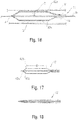
- the use of two such wires 42a, 42b is shown in Figure 16 .
- the wire(s) 42 may be made of metal or a like rigid material to provide the desired focused force for contacting the plaque Q, but the wire(s) could also be made of polymer materials.
- the presence of multiple wires, each having a radiographic quality, may help to distinguish between the flattened or pancaked condition and the inflated condition.
- the presence of three wires 42a, 42b, 42c having a radiopaque portion extending along the cone sections 18, 20, as shown in Figure 17 would cause the balloon 12 when deflated to appear remarkably different than in the inflated condition, as can be seen in balloon 12' in Figure 18 .
- the wire 42 or wires could be fabricated of special materials or combinations of materials.
- the wire 42 could be constructed having a segment that is fully or partially radiopaque, which segment 43 is compliant or semi-compliant (e.g., an elastic material or spring, which may be formed of a radiopaque material (polymer or metal); see schematic of Figure 19 ).
- the material may be chosen such that a stiffness of the segment 43 matches the compliance of the balloon 12, which is typically formed of a polymer, such as Nylon 12. Consequently, any longitudinal or radial elongation of the balloon working surface W under pressure would be matched by the radiopaque segment, with the remaining portions of the wire 42 being non-compliant and attached in place as previously described.
- the intermediate segment 43 of the wire 42 could be radiopaque (polymer or metal), but non-complaint, and the other portions made compliant (polymer or metal), to provide the desired match with the working surface W. Still another option is to make the intermediate portion compliant, and the ends of the wire radiopaque and non-compliant.
- the bonding may be accomplished by shrink-fitting a tubular end of one segment over the end of an adjacent segment to create a substantially continuous wire 42.
- One or more of the wires 42 may comprise a shape-memory material, such as NITINOL. Such materials may be set using temperature to achieve certain shapes.
- a shape-memory material such as NITINOL.
- NITINOL shape-memory material
- an external wire 42 could be arranged to lay in a nominal condition prior to full inflation (e.g., Figure 16 ), and then temperature activated (such as by the contrast fluid) to match the shape of the balloon 12 when fully inflated (see Figure 11 ). When deflated, the temperature of the surrounding blood and tissue could be used to re-activate the original memory and straighten the wire 42.
- the wire 42 or wires may also be used in connection with other radiopaque identifiers, such as patterns, bands, strips or the like. Details may be found in co-pending applications filed on the same date as this application, entitled “MEDICAL BALLOON WITH RADIOPAQUE IDENTIFIER FOR PRECISELY IDENTIFYING THE WORKING SURFACE,” for inventors Sean Wall, Pat Byrne, Robert Righi, Angela Crall, Paul Wales, and Allan Ronan, and “MEDICAL BALLOON WITH RADIOPAQUE END PORTION FOR PRECISELY IDENTIFYING A WORKING SURFACE LOCATION,” for inventors Sean Wall, Scott Randall, Robert Righi, Angela Crall. The disclosures of the foregoing applications are herein incorporated by reference.
- Balloons 12 that incorporate coatings comprising drugs to be applied to the vasculature may also benefit from the above-referenced embodiments.
- a balloon 12 including a defined working surface W such as by providing radiopaque markings 30 at the transitions between the barrel portion 16 and cone portions 18, 20, may include portion coated with such a drug D, such as one designed for achieving a desired therapeutic effect when applied to the interior of the vessel.
- the drug D may be applied to the inflated balloon as part of the manufacturing process, and prior to folding for insertion in the vasculature.
- the clinician may thus with the benefit of a fluoroscope determine the precise positioning of the working surface W prior to inflating the balloon 12 in the vasculature to deliver the drug D to the desired location and provide the desired treatment regimen.
- radiopaque materials include, but are not limited to, barium, bismuth, tungsten, iridium, iodine, gold, iron, or platinum. The amounts used may vary depending on the desired coverage and the desired degree of radiopacity.
Abstract
Description
- This disclosure relates generally to balloons for performing medical procedures, such as angioplasty and, more particularly, to a medical balloon having a predetermined portion, such as a working surface, that may be precisely located or identified during use.
- Balloons are routinely used to resolve or address flow restrictions or perhaps even complete blockages in tubular areas of the body, such as arteries or veins. In many clinical situations, the restrictions are caused by hard solids, such as calcified plaque, and require the use of high pressures to compact such blockages. Commercially available balloons employ complex technology to achieve high pressure requirements without sacrificing the profile of the balloon. Besides high pressure requirements, the balloons should also be resistant to puncture, easy to track and push, and present a low profile, especially when used for angioplasty.
In clinical practice, angioplasty balloons are expanded from a deflated, folded state to an expanded state within a vessel to treat a target area, such as a portion of the circumferential inner wall I of a blood vessel V, as shown inFigures 1 and 2 . The inflation is traditionally completed using an X-ray contrast agent to provide better visibility under X-ray or other form of radiography during the interventional procedure, as illustrated inFigures 3 and 3a . Typically, a 70/30 percent mixture of contrast agent and saline is used to inflate the balloon during an angioplasty procedure. The arrows R inFig. 3 indicate the direction of the X-ray beams.Fig. 3 further shows aconventional balloon 12 inflated with fluid containing contrast media. Further, reference sign CM refers to X-ray absorbing contrast media in the inflation fluid. Moreover, a fluoroscope detector plate FDP is shown. The length DX defines the long distance that X-ray beams travel through contrast media at the center of the balloon image.Fig. 3a shows the image intensity as a function of the image position. - In general, a desirable goal is to reduce inflation and deflation times required for balloons without sacrificing the profile of the balloons, especially for large volume balloons (which can require up to two minutes of inflation/deflation times with the contrast agent). Because of its relatively high viscosity, it would also be desirable to eliminate, or at least reduce the amount of, the contrast agent used in inflation/deflation of the balloons. The use of contrast agent prolongs the inflation/deflation times and also poses the risk of iodine exposure to patients sensitive to iodine. In this regard, a non-radiopaque substance could be used in lieu of the contrast agent, such as for example saline or carbon dioxide, but such substances are invisible during X-ray imaging, and thus do not enhance visibility.
- Furthermore, the physician performing the angioplasty procedure should be able to locate the position of the uninflated balloon with accuracy, so that the balloon will be properly positioned once inflated. This is conventionally accomplished by attaching marker bands on the catheter shaft in the region corresponding to the balloon working surface. This "working surface" is the surface along the portion of the balloon that is used to achieve the desired treatment effect, such as contacting the calcified plaque (which surface in the case of a balloon having conical or tapering sections at the proximal and distal ends is typically co-extensive with a generally cylindrical barrel section).
- Misalignment of the marker bands during placement along the shaft sometimes results in their failure to correspond precisely to the extent of the working surface, as is shown in
Figure 4 (note misalignment amount X between each interior marker band M carried by shaft S and working surface W ofballoon 12, which also typically includes a radiopaque tip P at the distal end). Even upon exercising great care to position the markers properly on the underlying shaft in alignment with anticipated boundaries of the working surface when the balloon is inflated, there remains a tendency for mismatch due to several possible factors. One such factor may be the tolerance stack-ups arising as a consequence of the affixation of the balloon to the distal end of the catheter shaft. The balloon also has a tendency to grow in the longitudinal direction when inflated, especially with large and particularly long balloons. Another factor is the tendency of the portion of the catheter shaft within the balloon to bend or flex during inflation. This may lead to misalignment between radiopaque markers fixed to the shaft and the working surface. - Whatever the cause, the resulting misalignment may prevent the clinician from accurately identifying the location of the working surface of the balloon during an interventional procedure. This may lead to a geographic misplacement, or "miss," of the intended contact between the target area T and the working surface W of the balloon 12 (see
Figure 2 ). It is especially desirable to avoid such an outcome when the balloon is designed to deliver a payload (such as a drug, stent, or both) or a working element to a specified location within the vasculature, since a miss may prolong the procedure (such as, for example, by requiring redeployment of theballoon 12 or the use of another balloon catheter in the case of a drug coated balloon). - Upon deflation, the balloon may also be subject to a phenomenon known as "pancaking." In this condition, the
balloon 12 folds down upon itself to a flattened state, as shown inFigure 5 . This situation may cause the balloon to be viewed through fluoroscopy as perhaps still being in the inflated condition, since the full width of the balloon may still be perceived. This can give the clinician the false perception that the balloon remains inflated, when in fact it is not. - Accordingly, the need is identified for a balloon for which the working surface may be identified during an interventional procedure with enhanced precision. The solution would take into account the possible mismatch between fixed locations on the catheter shaft and the balloon to define the working surface, and would operate independent of the position of the portion of the catheter shaft within the balloon. The improved identification may also allow for the better detection of the false perception of deflation caused by pancaking. Overall, procedural efficiency would be enhanced without remarkably increasing cost or complexity, and in a manner that can be applied to many existing catheter technologies without extensive modification.
- An object of the disclosure is to provide a balloon for which the working surface may be identified during an interventional procedure with enhanced precision.
- The description provided below and in regard to the figures applies to all embodiments unless noted otherwise, and features common to each embodiment are similarly shown and numbered.
- Provided is a
catheter 10 having adistal portion 11 with aballoon 12 mounted on acatheter tube 14. Referring toFigures 6, 7 , and8 , theballoon 12 has anintermediate section 16, or "barrel," andend sections end sections intermediate section 16 to the catheter tube 14 (and thussections balloon 12 is sealed at balloon ends (proximal end 15a anddistal end 15b) on thecone sections balloon 12 via one ormore inflation lumens 17 extending withincatheter tube 14 and communicating with the interior of theballoon 12. - The
catheter tube 14 also includes an elongated,tubular shaft 24 forming aguidewire lumen 23 that directs theguidewire 26 through thecatheter 10, and along the distal end of which theballoon 12 may be located. As illustrated inFigure 8 , thisguidewire 26 may extend through the proximal end of thecatheter 10 and afirst port 25 of aconnector 27 into thelumen 23 to achieve an "over the wire" (OTW) arrangement, but could also be provided in a "rapid exchange" (RX) configuration, in which theguidewire 26 exits alateral opening 14a closer to the distal end (seeFigure 9 ) or else is fed through a passage at the tip distally of the balloon 12 ("short" RX; not shown). Asecond port 29 may also be associated withcatheter 10, such as by way ofconnector 27, for introducing a fluid (e.g., saline, a contrast agent, or both) into the interior compartment of theballoon 12 via theinflation lumen 17. -
Balloon 12 may include a single ormulti-layered balloon wall 28 forming the interior for receiving the inflation fluid. Theballoon 12 may be a non-compliant balloon having aballoon wall 28 that maintains its size and shape in one or more directions when the balloon is inflated. Examples of non-compliant balloons may be found in U.S. Pat. No.6, 746, 425 and Publication Nos.US 2006/0085022 ,US 2006/0085023 andUS 2006/0085024 , the disclosures of which are hereby incorporated herein by reference. Theballoon 12 in such case also has a pre-determined surface area that remains constant during and after inflation, also has a pre-determined length and predetermined diameter that each, or together, remain constant during and after inflation. However, theballoon 12 could be semi-compliant or compliant instead, depending on the particular use. - In order to provide an enhanced locatability during an interventional procedure, the
balloon 12 may have a radiopaque quality. In one embodiment, this radiopaque quality is provided in a manner that allows for a clinician to differentiate, with relative ease and high precision, one portion of theballoon 12 from another (such as thebarrel section 16 including the working surface W from thecone sections 18, 20). This helps the clinician ensure the accurate positioning of theballoon 12 and, in particular, the working surface W, at a specified treatment location, which may be especially important in the delivery of drugs via the balloon surface, as outlined in more detail in the following description. - The identification of a desired portion of a
balloon 12 may be achieved by providing anidentifier 30 created by awire 42 that is at least partially radiopaque, as shown inFigure 10 (radiopacity ofidentifier 30 is shown darkened for purposes of illustration). Thewire 42 may extend along theballoon wall 28. More than onewire 42 may be provided, such as for example threewires wires Figure 12 ), within the interior (Figure 13 ), or a mixture of both arrangements (not shown). In any case, the proximal and distal ends of thewire 42 may be captured in place by being included in or connected to the bond used to seal theballoon 12 at the distal andproximal ends tube 14 and tip P, respectively). - Different portions of the
wire 42 may serve to provide the radiopacity, such as for identifying the working surface W in theballoon 12. For example, as shown inFigures 10 or 11 , the radiopacity may be provided along the entire portion of thewire 42 corresponding to the working surface W to create a correspondingidentifier 30. Alternatively, the radiopacity may be provided along the portions of thewire 42 other than along the working surface W, as shown by theidentifiers 30 inFigure 14 . Still another option is to provide the radiopaque portions of thewire 42 at the ends of the working surface W only, such as in the form of segments or bands, with an intermediate portion of thewire 42 extending along the working surface including no added radiopaque material, as shown inFigure 15 . - In addition to being radiopaque, the
wire 42 may be used to provide a focused force for contacting a structure in a vessel during use. Thus, for example, anexternal wire 42 in theFigure 10 embodiment may be used to contact a plaque Q in a vessel V when theballoon 12 is fully or partially inflated. The use of twosuch wires Figure 16 . In such uses, the wire(s) 42 may be made of metal or a like rigid material to provide the desired focused force for contacting the plaque Q, but the wire(s) could also be made of polymer materials. When using the embodiment in which the entire portion of thewire 42 corresponds to the working surface W, it should also be appreciated that the fluorescence of this portion of the wire(s) 42 contacting the structure in the vessel V allows for the clinician to ensure that the contact is being made in the desired fashion. Additional details may be found in International ApplicationWO 07/132447 - The presence of multiple wires, each having a radiographic quality, may help to distinguish between the flattened or pancaked condition and the inflated condition. For instance, the presence of three
wires cone sections Figure 17 , would cause theballoon 12 when deflated to appear remarkably different than in the inflated condition, as can be seen in balloon 12' inFigure 18 . - In one particular embodiment, the
wire 42 or wires could be fabricated of special materials or combinations of materials. For instance, thewire 42 could be constructed having a segment that is fully or partially radiopaque, whichsegment 43 is compliant or semi-compliant (e.g., an elastic material or spring, which may be formed of a radiopaque material (polymer or metal); see schematic ofFigure 19 ). The material may be chosen such that a stiffness of thesegment 43 matches the compliance of theballoon 12, which is typically formed of a polymer, such asNylon 12. Consequently, any longitudinal or radial elongation of the balloon working surface W under pressure would be matched by the radiopaque segment, with the remaining portions of thewire 42 being non-compliant and attached in place as previously described. Alternatively, theintermediate segment 43 of thewire 42 could be radiopaque (polymer or metal), but non-complaint, and the other portions made compliant (polymer or metal), to provide the desired match with the working surface W. Still another option is to make the intermediate portion compliant, and the ends of the wire radiopaque and non-compliant. In the case where different materials are used to form thewire 42 along its length, such as a polymer segment with metal ends, the bonding may be accomplished by shrink-fitting a tubular end of one segment over the end of an adjacent segment to create a substantiallycontinuous wire 42. - One or more of the
wires 42 may comprise a shape-memory material, such as NITINOL. Such materials may be set using temperature to achieve certain shapes. Thus, anexternal wire 42 could be arranged to lay in a nominal condition prior to full inflation (e.g.,Figure 16 ), and then temperature activated (such as by the contrast fluid) to match the shape of theballoon 12 when fully inflated (seeFigure 11 ). When deflated, the temperature of the surrounding blood and tissue could be used to re-activate the original memory and straighten thewire 42. - The
wire 42 or wires may also be used in connection with other radiopaque identifiers, such as patterns, bands, strips or the like. Details may be found in co-pending applications filed on the same date as this application, entitled "MEDICAL BALLOON WITH RADIOPAQUE IDENTIFIER FOR PRECISELY IDENTIFYING THE WORKING SURFACE," for inventors Sean Wall, Pat Byrne, Robert Righi, Angela Crall, Paul Wales, and Allan Ronan, and "MEDICAL BALLOON WITH RADIOPAQUE END PORTION FOR PRECISELY IDENTIFYING A WORKING SURFACE LOCATION," for inventors Sean Wall, Scott Randall, Robert Righi, Angela Crall. The disclosures of the foregoing applications are herein incorporated by reference. -
Balloons 12 that incorporate coatings comprising drugs to be applied to the vasculature may also benefit from the above-referenced embodiments. For example, as shown inFigure 10 , aballoon 12 including a defined working surface W, such as by providingradiopaque markings 30 at the transitions between thebarrel portion 16 andcone portions balloon 12 in the vasculature to deliver the drug D to the desired location and provide the desired treatment regimen. - Examples of suitable radiopaque materials include, but are not limited to, barium, bismuth, tungsten, iridium, iodine, gold, iron, or platinum. The amounts used may vary depending on the desired coverage and the desired degree of radiopacity.
- The subject matter of each of the paragraphs below citing a balloon or a catheter can be part of a balloon or a catheter respectively that is cited in any of the other paragraphs:
- 1.1 A balloon catheter, comprising: an elongated, tubular shaft extending in a longitudinal direction, said shaft having a proximal end and a distal end; and an inflatable balloon supported along the distal end of the shaft, the balloon when inflated including first and second spaced conical end sections and a working surface between the conical sections, the balloon further including at least one radiopaque marking identifying the transition from the conical end section to the working surface.
- 1.2 The catheter of paragraph 1.1, wherein the at least one radiopaque marking comprises a first radiopaque marking at a first transition between the first conical end section and the working surface, and further including a second radiopaque marking at a second transition between the second conical end section and the working surface.
- 1.3 The catheter of any of the foregoing paragraphs, wherein the at least one marking comprises a strip.
- 1.4 The catheter of any of the foregoing paragraphs, further including a plurality of radiopaque markings in the form of strips.
- 1.5 The catheter of paragraph 1.4, wherein the strips extend at least partially in a longitudinal direction between the first and second conical end sections.
- 1.6 The catheter of paragraphs 1.4 or 1.5, wherein the strips comprise annular bands.
- 1.7 The catheter of any of the foregoing paragraphs, wherein at least two spaced radiopaque markings are provided on each conical end section, including one adjacent a distal portion and a proximal portion of each conical end section.
- 1.8 The catheter of any of the foregoing paragraphs, wherein the balloon includes a barrel section between the first and second conical end sections, and further including a plurality of radiopaque markings on the barrel section.
- 1.9 The catheter of any of the foregoing paragraphs, wherein the marking comprises a first pattern on the conical end sections and further including a second, different pattern on the working surface.
- 1.10 The catheter of any of the foregoing paragraphs, wherein the at least one marking is selected from the group consisting of a pattern, a strip, a brand, a logo, a letter, a number, a word, or combinations thereof.
- 1.11 The catheter of any of the foregoing paragraphs, wherein the identifier comprises a scale.
- 1.12 The catheter of any of the foregoing paragraphs, wherein the balloon includes a drug.
- 1.13 The catheter of paragraph 1.12, wherein the drug corresponds to the location of the radiopaque marking.
- 1.14 The catheter of paragraph 1.12, wherein the drug corresponds to other than the location of the radiopaque marking.
- 1.15 The catheter of paragraph 1.12, wherein the radiopaque marking comprises the drug formulated to include a radiopacifier.
- 1.16 A balloon having a drug carried on a working surface of the balloon wall and a radiopaque identifier identifying the location of the drug on the balloon.
- 1.17 The balloon of paragraph 1.16, wherein the radiopaque identifier comprises a radiopaque material mixed with a formulation comprising the drug.
- 1.18 The balloon of paragraph 1.16, wherein the working surface is along a barrel section of the balloon, and the radiopaque identifier is on one or both cone sections of the balloon.
- 2.1 A balloon catheter, comprising: an elongated, tubular shaft extending in a longitudinal direction, said shaft having a proximal end and a distal end; and an inflatable balloon supported along the distal end of the shaft, the balloon when inflated including a generally cylindrical barrel section forming a working surface, and generally conical end sections that do not form a part of the working surface, the balloon further including at least one radiopaque identifier for indicating the relative position of the working surface, said identifier being provided on at least one of the conical end sections of the balloon so as to define the extent of the working surface.
- 2.2 The catheter of paragraph 2.1, wherein the identifier comprises a marking.
- 2.3 The catheter of paragraph 2.1 or 2.2, wherein a first marking is provided at a first transition between the first conical section end section and the working surface and a second marking is provided at a second transition between the second end section and the working surface.
- 2.4 The catheter of paragraph 2.2 or 2.3, wherein the marking comprises a strip.
- 2.5 The catheter of any of the foregoing paragraphs, wherein the identifier comprises a longitudinal strip extending between an end of the balloon and the barrel section.
- 2.6 The catheter of any of the foregoing paragraphs, further including a plurality of identifiers.
- 2.7 The catheter of paragraph 2.6, wherein each of the plurality of identifiers comprises a longitudinally extending strip.
- 2.8 The catheter of paragraph 2.6 or 2.7, wherein the identifiers comprise annular bands.
- 2.9 The catheter of paragraph 2.6 or paragraph 2.8 as dependent on paragraph 2.6, wherein the identifiers comprise longitudinally extending strips.
- 2.10 The catheter of any of the foregoing paragraphs 2.1 to 2.9, wherein at least two spaced radiopaque identifiers are provided on each end section.
- 2.11 The catheter of any of the foregoing paragraphs 2.1 to 2.10, further including at least one radiopaque identifier on the barrel section.
- 2.12 The catheter of any of the foregoing paragraphs 2.1 to 2.11, wherein the identifier is a first identifier comprising a first pattern, and further including a second identifier comprising a second, different pattern.
- 2.13 The catheter of any of the foregoing paragraphs 2.1 to 2.12, wherein the identifier includes at least one letter or number.
- 2.14 The catheter of any of the foregoing paragraphs 2.1 to 2.13, wherein the identifier comprises a logo.
- 2.15 The catheter of any of the foregoing paragraphs 2.1 to 2.14, wherein the identifier comprises a scale.
- 2.16 The catheter of any of the foregoing paragraphs 2.1 to 2.15, further including a drug on the balloon.
- 3.1 An inflatable balloon for use in connection with a catheter, comprising: an inflatable body including a working surface extending in a longitudinal direction between a first end and a second end, the body having at least one radiopaque identifier provided along the body for identifying at least a first end of the working surface, the radiopaque identifier having a first radiographic quality for identifying the location of the first end of the working surface and a second radiographic quality at a location other than at the first end of the working surface.
- 3.2 The balloon of paragraph 3.1, wherein the second radiographic quality is provided for identifying the second end of the working surface.
- 3.3 The catheter of paragraph 3.2, wherein the first radiographic quality and the second radiographic quality are substantially the same.
- 3.4 The balloon of paragraph 3.1, wherein the radiopaque identifier comprises a marking.
- 3.5 The balloon of paragraph 3.1, wherein the radiopaque identifier follows a generally helical path from the first end to the second end of the working surface.
- 3.6 The balloon of paragraph 3.1, wherein the identifier comprises a plurality of helical identifiers extending along the working surface.
- 3.7 The balloon of paragraph 3.1, wherein the identifier comprises a radiopaque filament.
- 3.8 The balloon of paragraph 3.7, wherein the filament is wound helically along at least a portion of the working surface of the balloon.
- 3.9 The balloon of any of the foregoing paragraphs 3.1 to 3.8, further including a drug on the balloon.
- 3.16 A balloon for use in connection with a catheter, comprising: a body having an outer surface and at least one winding extending along the outer surface of the balloon, said balloon having a radiopaque quality.
- 3.17 The balloon of paragraph 3.16, wherein the winding comprises a radiopaque filament.
- 3.18 The balloon of any of the foregoing paragraphs, wherein the radiopaque identifier comprises a helical pattern or a diamond pattern.
- 3.19 A catheter including the balloon of any of the foregoing paragraphs.
- 3.20 An inflatable balloon for use in connection with a catheter comprising a radiopaque identifier comprising a helical pattern or a diamond, pattern.
- 4.1 A balloon catheter for use in connection with a guidewire, comprising: an elongated, tubular shaft extending in a longitudinal direction, said shaft having a proximal end and a distal end; an inflatable balloon supported along the distal end of the shaft, the balloon when inflated including first and second spaced ends and a working surface between the ends; and at least one wire including at least a radiopaque portion for identifying the location of working surface of the balloon.
- 4.2 The catheter of paragraph 4.1, wherein said wire comprises a material having a shape memory for adjusting between a first state and a second state.
- 4.3 The catheter of paragraph 4.1 or 4.2, wherein the at least one wire extends generally in the longitudinal direction.
- 4.4 The catheter of any of the foregoing paragraphs 4.1 to 4.3, wherein the radiopaque portion is elongated.
- 4.5 The catheter of any of the foregoing paragraphs 4.1 to 4.4, wherein the wire at least partially comprises a polymer.
- 4.6 The catheter of any of the foregoing paragraphs 4.1 to 4.5, wherein the at least one wire is at least partially elastic.
- 4.7 The catheter of any of the foregoing paragraphs 4.1 to 4.6, comprising: a plurality of wires extending generally in the longitudinal direction, at least one of the wires including at least a radiopaque portion for identifying the location of working surface of the balloon.
- 4.8 The catheter of any of the foregoing paragraphs 4.1 to 4.7, wherein at least one wire extends along an outer surface of the balloon.
- 4.9 The catheter of any of the foregoing paragraphs 4.1 to 4.8, wherein at least one wire extends along an inner surface of the balloon.
- 4.10 The catheter of any of the foregoing paragraphs 4.1 to 4.9, wherein at least one wire extends from the first end to the second end of the balloon.
- 4.11 The catheter of any of the foregoing paragraphs 4.1 to 4.10, wherein the radiopaque portion of at least one wire extends along a portion of the balloon corresponding to the working surface.
- 4.12 The catheter of any of the foregoing paragraphs 4.1 to 4.11, wherein the radiopaque portion of at least one wire extends along other than along the portion of the balloon corresponding to the working surface.
- 4.13 The catheter of paragraph 4.7 or any of paragraphs 4.8 to 4.12 as dependent on paragraph 4.7, wherein the wires are spaced substantially equidistantly around a circumference of the balloon.
- 4.14 The catheter of any of the foregoing paragraphs 4.1 to 4.13, wherein the wire includes a compliant or semi-compliant portion.
- 4.15 The catheter of any of the foregoing paragraphs 4.1 to 4.14, wherein at least one end of the at least partially radiopaque wire is attached to a bond connecting the balloon to the shaft.
- 4.16 The catheter of any of the foregoing paragraphs 4.1 to 4.15, further including a drug provided on the balloon.
- 4.17 The catheter of any of the foregoing paragraphs 4.1. to 4.16, wherein at least one wire at least partially comprises a material having a shape memory for adjusting between a first state and a second state.
- 4.18 The catheter of paragraph 4.2 or 4.17, wherein the shape memory material comprises NITINOL.
- 5.1 A balloon catheter adapted for use with a guidewire, comprising: an elongated, tubular shaft extending in a longitudinal direction, said shaft having a proximal end and a distal end; an inflatable balloon supported along the distal end of the shaft, the balloon when inflated including first and second spaced ends and a working surface between the ends; and an insert located within the interior compartment of the balloon, the insert including at least a radiopaque portion separate from the shaft.
- 5.2 The catheter of paragraph 5.1, wherein the insert is adapted for moving relative to the shaft.
- 5.3 The catheter of paragraph 5.1 or 5.2, wherein the insert extends from a first end of the balloon to one end of the working surface.
- 5.4 The catheter of any of the foregoing paragraphs 5.1 to 5.3, wherein the insert comprises a tube made at least partially of a radiopaque material.
- 5.5 The catheter of any of the foregoing paragraphs 5.1 to 5.4, wherein the insert comprises at least one finger.
- 5.6 The catheter of paragraph 5.5, wherein the finger includes a radiopaque end portion.
- 5.7 The catheter of any of the foregoing paragraphs 5.1 to 5.6, wherein the insert comprises a plurality of fingers adapted for moving from a retracted condition to an expanded condition when the balloon is inflated.
- 5.8 The catheter of any of the foregoing paragraphs 5.1 to 5.7, further including a retractable sheath at least partially covering the insert.
- 5.9 The catheter of any of the foregoing paragraphs 5.1 to 5.8, wherein the insert comprises a wire.
- 5.10 The catheter of paragraph 5.9, wherein the wire includes a radiopaque portion corresponding to the working surface.
- 5.11 The catheter of paragraph 5.10, wherein the wire extends from the first end to the second end of the balloon, and the radiopaque portion comprises an intermediate portion of the wire.
- 5.12 The catheter of paragraph 5.10 or 5.11, wherein the wire extends from the first end to the second end of the balloon, and the radiopaque portion comprises an end portion of the wire.
- 5.13 The catheter of any of the foregoing paragraphs 5.1 to 5.12, wherein at least one end of the insert is connected at a location where the balloon connects to the tubular shaft.
- 5.14 The catheter of any of the foregoing paragraphs 5.1 to 5.13, wherein the insert comprises an annular band.
- 5.15 The catheter of any of the foregoing paragraphs 5.1 to 5.14, wherein the insert includes perforations.
- 5.16 The catheter of any of the foregoing paragraphs 5.1 to 5.15, wherein the insert comprises a material having α shape memory.
- 5.17 The catheter of any of the foregoing paragraphs 5.1 to 5.16, further including a drug on the balloon.
- 6.1 A parison for being blow molded into a medical balloon for a catheter, comprising: a first tubular layer having a functional modification; and a second tubular layer adapted for bonding with the first tubular layer to form the blow molded balloon.
- 6.2 The parison of paragraph 6.1, wherein the first layer is external to the second layer.
- 6.3 The parison of paragraph 6.1, wherein the first layer is internal to the second layer.
- 6.4 The parison of any of the foregoing paragraphs, wherein the functional modification comprises a radiopaque strip.
- 6.5 The parison of paragraph 6.4, wherein the strip comprises a circumferential band.
- 6.6 The parison of paragraph 6.4 or 6.5, wherein the strip extends between a first end and a second end of the first layer .
- 6.7 The parison of any of the foregoing paragraphs, wherein the first tubular layer is spaced from the second tubular layer.
- 6.8 The parison of any of the foregoing paragraphs, wherein the functional modification is selected from the group consisting of an added radiopacifier, a surface pattern, an etching, one or more perforations, and combinations of the foregoing.
- 6.9 A medical balloon formed by the parison of any of the foregoing paragraphs, comprising: a tubular, inflatable body comprising a wall, the body including first and second generally conical ends and a generally cylindrical barrel section between the generally conical ends and providing a working surface.
- 6.10 The balloon of paragraph 6.9, wherein the first layer extends from the first end to the second end of the balloon.
- 6.11 The balloon of paragraph 6.9, wherein the first layer extends along only the working surface.
- 6.12 The balloon of any of paragraphs 6.9 to 6.11, wherein the first layer extends along an entire circumference of a portion of the wall.
- 6.13 The balloon of any of paragraphs 6.9 to 6.12, wherein the first layer extends along the full circumference of the wall.
- 6.14 The balloon of any of paragraphs 6.9 to 6.13, wherein the wall includes first and second spaced shoulders, and wherein the first layer is positioned between the shoulders.
- 6.15 The balloon of any of paragraphs 6.9 to 6.14, wherein the first and second layers both extend from a first end to a second end of the balloon.
- 6.16 The balloon of any of paragraphs 6.9 to 6.15, further comprising an at least partially radiopaque tube positioned over the barrel section and extending substantially along the working surface.
- 6.17 The balloon of paragraph 6.16, further including first and second shoulders adjacent the proximal and distal ends of the radiopaque tube.
- 6.18 The balloon of paragraph 6.16 or 6.17, wherein the entire tube is radiopaque.
- 7.1 A balloon catheter , comprising: an elongated, tubular shaft having a proximal end and a distal end; and a balloon positioned along the distal end of the shaft, a portion of a wall of the balloon partially comprising a coextruded radiopaque material.
- 7.2 The catheter of paragraph 7.1, wherein the radiopaque portion comprises at least one strip extending along a working surface of the balloon.
- 7.3 The catheter of paragraph 7.1 or 7.2, wherein the radiopaque portion comprises at least one strip extending along a full length surface of the balloon.
- 7.4 The catheter of any of paragraphs 7.1 to 7.3, wherein the radiopaque portion comprises at least one strip extending along a first cone section of the balloon.
- 7.5 The catheter of paragraph 7.4, wherein the radiopaque portion comprises at least one strip extending along a second cone section of the balloon.
- 7.6 The catheter of any of paragraphs 7.1 to 7.5, wherein the balloon includes a plurality of radiopaque portions.
- 7.7 The catheter of paragraph 7.6, wherein each of the plurality of radiopaque portions comprises a longitudinal strip.
- 7.8 The catheter of paragraph 7.7, wherein the strips extend at least along a working surface of the balloon.
- 7.9 The catheter of any of paragraphs 7.6 to 7.8, wherein the plurality of radiopaque portions are spaced apart in a circumferential direction.
- 7.10 The catheter of any of the foregoing paragraphs 7.1 to 7.9, wherein the balloon includes a barrel section and conical sections at each end of the barrel section, and wherein the radiopaque portion is provided on the barrel section.
- 7.11 The catheter of any of the foregoing paragraphs 7.1 to 7.10, wherein the balloon includes a barrel section and conical sections at each end of the barrel section, and wherein the radiopaque portion is provided on one or both of the cone sections.
- 7.12 The catheter of any of the foregoing paragraphs 7.1 to 7.11, wherein the radiopaque portion comprises a layer of the balloon wall.
- 7.13 The catheter of paragraph 7.12, wherein the layer comprises an inner layer.
- 7.14 The catheter of paragraph 7.12 or 7.13, wherein the layer comprises an outer layer.
- 7.15 The catheter of paragraph 7.14, wherein the outer layer is etched.
- 7.16 The catheter of any of paragraphs 7.12 to 7.15, wherein the balloon includes a barrel section and conical sections at each end of the barrel section, and the layer extends along the entire barrel section.
- 7.17 The catheter of any of paragraphs 7.12 to 7.16, wherein the balloon includes a barrel section and conical sections at each end of the barrel section, and the layer extends along the entirety of one or both of the conical sections.
- 7.18 The catheter of any of the foregoing paragraphs 7.1 to 7.17, wherein all portions of the wall comprise coextruded radiopaque material.
- 7.19 The catheter of any of the foregoing paragraphs 7.1 to 7.18, further including a drug on the balloon.
- 7.20 The catheter of any of the foregoing paragraphs 7.1 to 7.19, wherein the radiopaque material comprises ePTFE.
- 8.1 A balloon catheter, comprising: a shaft extending in a longitudinal direction, said shaft having a proximal end and a distal end, and supporting at least one radiopaque identifier; an inflatable balloon supported along the distal end of the shaft, the balloon when inflated including a working surface; and an actuator for aligning at least one end of the working surface with the at least one radiopaque identifier.
- 8.2 The catheter of paragraph 8.1, wherein the actuator includes a first position corresponding to a deflated state of the balloon and a second position corresponding to the inflated state of the balloon.
- 8.3 The catheter of paragraph 8.1 or 8.2, wherein the actuator comprises a spring.
- 8.4 The catheter of any of the foregoing paragraphs 8.1 to 8.3, wherein the spring comprises a leaf spring.
- 8.5 The catheter of any of the foregoing paragraphs 8.1 to 8.4, wherein the actuator comprises a plurality of springs spaced circumferentially about the catheter.
- 8.6 The catheter of any of the foregoing paragraphs 8.1 to 8.5, wherein a first portion of the actuator is fixed to the balloon and a second portion of the actuator is adapted for movement relative to the shaft.
- 8.7 The catheter of paragraph 8.6, wherein the first portion of the actuator is captured between two layers on the wall of the balloon.
- 8.8 The catheter of paragraph 8.6 or 8.7, wherein the shaft includes a channel for at least partially receiving the second portion of the actuator.
- 8.9 The catheter of any of the foregoing paragraphs 8.1 to 8.8, further including a stop for stopping the movement of the actuator.
- 8.10 The catheter of any of the foregoing paragraphs 8.1 to 8.9, wherein the radiopaque identifier comprises a marker attached to the shaft.
- 8.11 The catheter of any of the foregoing paragraphs 8.1 to 8.10, wherein the radiopaque identifier comprises an insert positioned within the interior compartment of the balloon.
- 8.12 The catheter of any of the foregoing paragraphs 8.1 to 8.11, wherein the actuator is a first actuator for aligning a distal end of the working surface with the radiopaque identifier, and further including a second actuator for aligning a proximal end of the working surface with the radiopaque identifier.
- 8.13 The catheter of paragraph 8.12, wherein each of the first and second actuators comprise a plurality of springs.
- 8.14 The catheter of any of the foregoing paragraphs, wherein the radiopaque identifier comprises a first marking and a second marking, and wherein the actuator is a first actuator for aligning a distal end of the working surface with the first marking, and further including a second actuator for aligning a proximal end of the working surface with the second marking.
- 8.15 The balloon catheter of any of the foregoing paragraphs 8.1 to 8.14, comprising: a shaft extending in a longitudinal direction, said shaft having a proximal end and a distal end, and supporting first and second radiopaque identifiers; a first actuator for aligning a first end of the working surface with the first radiopaque marking; and a second actuator for aligning a second end of the working surface with the second radiopaque identifier.
- 8.16 The balloon catheter of any of the foregoing paragraphs 8.1 to 8.15, comprising: a shaft for carrying the balloon, the shaft including at least one channel formed in an outer portion of a wall of the shaft; and an actuator having a first end connected to the balloon and a second end at least partially positioned in the channel.
- 8.17 The balloon catheter of any of the foregoing paragraphs 8.1 to 8.16, comprising: shaft for carrying the balloon, the shaft including a plurality of channels formed in an outer portion of the wall of the shaft.
- 8.18 The catheter of paragraph 8.17, further including an actuator having a first end connected to the balloon and a second end positioned in at least one of the channels.
- 8.19 The catheter of any of the foregoing paragraphs 8.1 to 8.8, comprising: a spring connected to a wall of the balloon.
- 8.20 The catheter of paragraph 8.19, wherein the spring is at least partially radiopaque.
- 8.21 The catheter of paragraph 8.19 or 8.20, wherein the spring is connected to a conical section of the wall of the balloon.
- 8.22 The balloon catheter of any of the foregoing paragraphs 8.1 to 8.21, wherein the balloon includes a drug.
- 9.1 A balloon catheter for use with a guidewire, comprising: an elongated, tubular shaft extending in a longitudinal direction, said shaft having a proximal end and a distal end; an inflatable balloon connected to the distal end of the shaft, the balloon including a working surface; a radiopaque identifier for identifying the working surface; and a receiver adjacent the proximal end of the shaft and adapted for allowing the shaft to move relative to the receiver in at least the longitudinal direction.
- 9.2 The catheter of paragraph 9.1, wherein the shaft carries a stop, and the receiver further includes a recess for receiving the stop, said recess having a dimension in the longitudinal direction that is greater than a corresponding dimension of the stop.
- 9.3 The catheter of paragraph 9.2, further including a tube for supplying an inflation fluid to inflate the balloon, said tube being connected to the receiver and generally coaxial with the shaft, and wherein the stop forms a seal with the recess to prevent the inflation fluid from passing around the shaft.
- 9.4 The catheter of paragraph 9.3, wherein the seal comprises an O-ring arranged coaxially with the shaft.
- 9.5 The catheter of paragraph 9.1, wherein the radiopaque identifier is separate from the shaft.
- 9.6 The catheter of paragraph 9.5, wherein the radiopaque identifier comprises an insert positioned within the interior compartment of the balloon.
- 9.7 The catheter of paragraph 9.6, wherein the insert comprises a tubular sleeve arranged coaxially with the shaft.
- 9.8 The catheter of paragraph 9.6, wherein the insert comprises a first insert at a proximal end of the balloon and a second insert at a distal end of the balloon.
- 9.9 The catheter of paragraph 9.1, further including a guidewire for positioning in the shaft.
- 9.10 A hub for a balloon catheter having an elongated, tubular shaft extending in a longitudinal direction, said shaft having a proximal end and a distal end, and an inflatable balloon connected to the distal end of the shaft for being inflated by an inflation fluid, comprising: a body including a receiver for receiving a proximal portion of the shaft and adapted for allowing the shaft to move relative to the receiver in at least the longitudinal direction; and a stop for restraining the movement of the shaft relative to the body in the longitudinal direction.
- 9.11 The hub of paragraph 9.10, wherein the body includes a guidewire port arranged in communication with the receiver, and further including an inflation port for introducing the inflation fluid for inflating the balloon.
- 9.12 The hub of paragraph 9.10, wherein the receiver further includes a recess for receiving the stop, said recess having a dimension in the longitudinal direction that is greater than a corresponding dimension of the stop.
- 9.13 The hub of paragraph 9.12, wherein the stop forms a seal with the recess to prevent the inflation fluid from passing.
- 9.14 The hub of paragraph 9.10, wherein the stop comprises an O-ring.
- 9.15 A catheter including a guidewire shaft having a distal end connected to a balloon and at a proximal end mounted for sliding movement.
- 9.16 The catheter of any of the foregoing paragraphs, further including a drug on the balloon.
- 9.17 A catheter comprising a hub for receiving a proximal end of a guidewire shaft, the shaft being adapted to slidably move in a restrained manner relative to the hub.
- 10.1 A balloon catheter, comprising: an elongated tubular shaft having a proximal end and a distal end spaced apart in a longitudinal direction, the shaft along a distal portion including at least one radiopaque identifier, said distal portion being formed of a material resistant to elongation in the longitudinal direction; and an inflatable, non-compliant balloon extending over the distal portion of the shaft.
- 10.2 The catheter according to paragraph 10.1, wherein the balloon includes a generally cylindrical barrel section positioned between generally conical sections, said barrel section including a working surface having at least one edge aligned with the radiopaque identifier.
- 10.3 The catheter according to paragraph 10.2, wherein the radiopaque identifier comprises a first marker positioned at the at least one edge of the working surface, and further including a second marker positioned at the opposite edge of the working surface in the longitudinal direction.
- 10.4 The catheter according to paragraph 10.2, wherein each marker comprises a radiopaque band swaged to the distal portion of the shaft.
- 10.5 The catheter according to paragraph 10.1, wherein the distal portion of the shaft comprises a tube adapted for guiding a guidewire from a proximal end of the balloon to a distal end of the balloon.
- 10.6 The catheter according to paragraph 10.1, wherein at least the distal portion of the shaft comprises steel.
- 10.7 The catheter according to paragraph 10.1, wherein the shaft comprises steel.
- 10.8 The catheter according to paragraphs 10.6 or 10.7, wherein the steel shaft comprises a stainless steel.
- 10.9 The catheter according to paragraphs 10.7 or 10.8, wherein the steel shaft includes a spiral cut along a portion other than the distal portion covered by the balloon.
- 1.0.10 The catheter according to paragraphs 10.7 or 10.8, wherein the steel shaft comprises a polymer layer.
- 10.11 The catheter according to paragraph 10.10, wherein the polymer layer comprises an outer layer of the shaft.
- 10.12 The catheter according to paragraph 10.1, wherein the distal portion of the shaft comprises a polymer shaft including a braid or mesh.
- 10.13 The catheter according to paragraph 10.1, wherein the balloon includes a generally cylindrical barrel section positioned between generally conical sections, the distal portion of the shaft extending from a first end of a first conical section to a second end of a second conical section.
- 10.14 The catheter according to paragraph 10.1, wherein the non-compliant balloon comprises one or more inelastic fibers.
- 10.15 The catheter according to paragraph 10.1, wherein the non-compliant balloon comprises polyethylene terephthalate.
- 10.16 The catheter of any of the foregoing paragraphs 10.1 to 10.15, further including a drug on the balloon.
- 11.1 A balloon catheter, comprising: a shaft extending in a longitudinal direction and adapted for expanding from a compressed condition to an expanded condition in the longitudinal direction, the shaft supporting at least one radiopaque identifier; and an inflatable balloon positioned along the shaft, the balloon when inflated including a working surface for aligning with the radiopaque identifier in at least the expanded condition of the shaft.
- 11 .2 The catheter of paragraph 11.1, wherein the expandable shaft comprises a first portion connected in tandem to an expandable element.
- 11.3 The catheter of paragraphs 11.1 or 11.2, wherein the expandable element comprises a spring.
- 11.4 The catheter of paragraph 11.3, wherein the spring comprises a coil spring.
- 11.5 The catheter of paragraphs 11.3 or 11.4, wherein the spring comprises a tension coil spring.
- 11.6 The catheter of paragraph 11.2, wherein the expandable element comprises a bellows.
- 11.7 The catheter of paragraph 11.2, wherein the expandable element comprises a fiber matrix.
- 11.8 The catheter of paragraph 11.7, further including a spring associated with the fiber matrix.
- 11.9 The catheter of any of paragraphs 11.2-11.8, wherein the expandable element is inside an interior compartment of the balloon.
- 11.10 The catheter of any of paragraphs 11.2-11.8, wherein the expandable element is outside an interior compartment of the balloon.
- 11.11 The catheter of any of paragraphs 11.2-11.10, wherein the expandable element connects to one end of the balloon.
- 11.12 The catheter of any of paragraphs 11.2-11.10, wherein the expandable element connects the first portion of the shaft to a second portion of the shaft.
- 11.13 The catheter of any of the foregoing paragraphs 11.1 to 11.12, wherein the shaft comprises an inflation lumen for delivering an inflation fluid to the balloon.
- 11.14 The catheter of any of the foregoing paragraphs 11.1 to 11.13, wherein the expandable shaft in at least a partially expanded condition a port for delivering the inflation fluid to the balloon, said port being closed when the shaft is in a non-expanded condition.
- 11.15 The catheter of any of the foregoing paragraphs 11.1 to 11.14, wherein the expandable shaft comprises a first expandable element connecting a first portion of the shaft to a second portion of the shaft, and further including a second expandable element connecting the second portion of the shaft to a third portion of the shaft.
- 11.16 The catheter of paragraph 11.15, wherein the first and second expandable elements comprise first and second coil springs.
- 11.17 The catheter of paragraph 11.16, wherein the first and second coil springs have different spring constants.
- 11.18 The catheter of any of the foregoing paragraphs 11.1 to 11.17, wherein the radiopaque identifier comprises a pair of spaced radiopaque markers, one positioned in alignment with a first end of the working surface and another positioned at a second end of the working surface.
- 11.19 The catheter of any of paragraphs 11.15-11.18, wherein the first and second expandable elements comprise a radiopaque material.
- 11.20 The catheter of any of the foregoing paragraphs 11.1 to 11.19, wherein the radiopaque identifier comprises a spring.
- 11.21 The catheter of paragraph 11.2, wherein the expandable element comprises a spring having a variable spring constant.
- 11.22 The catheter of any of the foregoing paragraphs 11.1 to 11.21, wherein the shaft comprises a guidewire lumen.
- 11.23 The catheter of any of the foregoing paragraphs 11.1 to 11.22, further including a passage adjacent the tip for receiving a guidewire external to the balloon.
- 11.24 The catheter of paragraph 11.2, wherein the first portion is adjacent a distal end of the shaft.
- 11.25 A balloon catheter, comprising: a shaft; a balloon; and an expandable element adapted for expanding in the longitudinal direction connecting the shaft to the balloon.
- 11.26 The catheter of paragraph 11.25, wherein the expandable element is selected from the group consisting of a spring, a bellows, a fiber matrix, or combinations of the foregoing.
- 11.27 The catheter of paragraph 11.25 or 26, wherein the expandable element comprises an encapsulated spring.
- 11.28 A balloon catheter comprising a balloon and an inflation lumen including an expandable element adapted for expanding in the longitudinal direction for providing a fluid to the balloon.
- 11.29 The catheter of any of paragraphs 11.25-11.28, wherein the expandable element comprises a radiopaque material.
- 11.30 The catheter of any of the foregoing paragraphs 11.1 to 11.29, further including a drug on the balloon.
- 12.1 A balloon catheter, comprising: an elongated, tubular shaft extending in a longitudinal direction, said shaft having a proximal end and a distal end; and a balloon having an inflation compartment formed a balloon wall including a working surface, and further including at least one chamber adjacent to the working surface adapted for receiving an identifier for identifying the location of the working surface.
- 12.2 The balloon catheter of paragraph 12.1, wherein the shaft includes a first lumen for supplying a fluid to the chamber.
- 12.3 The balloon catheter of paragraph 12.2, wherein the shaft includes a port between the first lumen and the chamber.
- 12.4 The balloon catheter of paragraph 12.2, wherein the shaft includes a second lumen for supplying a fluid to an interior compartment of the balloon.
- 12.5 The balloon catheter of paragraph 12.4, wherein the shaft includes a port between the second lumen and the interior compartment.
- 12.6 The balloon catheter of any of the foregoing paragraphs 12.1 to 12.5, wherein the identifier comprises a contrast agent.
- 12.7 The balloon catheter of any of the foregoing paragraphs 12.1 to 12.6, wherein the contrast agent comprises a material selected from the group consisting of a radiopacifier, polyvinyl acetate, cellulose, a fluid, a liquid, a solid, a powder, or combinations of the foregoing.
- 12.8 The balloon catheter of any of the foregoing paragraphs 12.1 to 12.7, wherein the chamber comprises a first chamber at a proximal end of the balloon, and further including a second chamber at a distal end of the balloon.
- 12.9 The balloon catheter of paragraph 12.8, wherein the second chamber is adapted for receiving the identifier from a lumen in the shaft in fluid communication with the first chamber via a port.
- 12.10 The balloon catheter of any of the foregoing paragraphs 12.1 to 12.9, wherein the chamber is generally annular.
- 12.11 The balloon catheter of any of the foregoing paragraphs 12.1 to 12.10, wherein the chamber is positioned between a transition from a barrel section to a conical section of the balloon and an end of the balloon.
- 12.12 The balloon catheter of any of the foregoing paragraphs 12.1 to 12.11, wherein the chamber is provided by a film attached to the balloon wall.
- 12.13 The balloon catheter of any of the foregoing paragraphs 12.1 to 12.12, wherein the chamber is embedded in the balloon wall.
- 12.14 The balloon catheter of any of the foregoing paragraphs 12.1 to 12.13, wherein the chamber is provided by a film extending between the balloon wall and an outer surface of the shaft.
- While the disclosure presents certain embodiments to illustrate the inventive concepts, numerous modifications, alterations, and changes to the described embodiments are possible without departing from the sphere and scope of the present invention, as defined in the appended claims. For example, any ranges and numerical values provided in the various embodiments are subject to variation due to tolerances, due to variations in environmental factors and material quality, and due to modifications of the structure and shape of the balloon, and thus can be considered to be approximate and the term "approximately" means that the relevant value can, at minimum, vary because of such factors. Accordingly, it is intended that the present invention not be limited to the described embodiments, but that it has the full scope defined by the language of the following claims, and equivalents thereof.
-
- 1. A balloon catheter for use in connection with a guidewire, comprising:
- an elongated, tubular shaft extending in a longitudinal direction, said shaft having a proximal end and a distal end;
- an inflatable balloon supported along the distal end of the shaft, the balloon when inflated including first and second spaced ends and a working surface between the ends; and
- at least one wire including at least a radiopaque portion for identifying the location of working surface of the balloon.
- 2. The catheter of item 1, wherein said wire comprises a material having a shape memory for adjusting between a first state and a second state.
- 3. The catheter of item 1 or 2, wherein
the at least one wire extends generally in the longitudinal direction. - 4. The catheter of any of the foregoing items , wherein the radiopaque portion is elongated.
- 5. The catheter of any of the foregoing items, wherein
the wire at least partially comprises a polymer. - 6. The catheter of any of the foregoing items, wherein the at least one wire is at least partially elastic.
- 7. The catheter of any of the foregoing items, comprising:
a plurality of wires extending generally in the longitudinal direction, at least one of the wires including at least a radiopaque portion for identifying the location of working surface of the balloon. - 8. The catheter of any of the foregoing items, wherein at least one wire extends along an outer surface of the balloon.
- 9. The catheter of any of the foregoing items , wherein at least one wire extends along an inner surface of the balloon.
- 10. The catheter of any of the foregoing items, wherein at least one wire extends from the first end to the second end of the balloon.
- 11. The catheter of any of the foregoing items, wherein the radiopaque portion of at least one wire extends along a portion of the balloon corresponding to the working surface.
- 12. The catheter of any of the foregoing items, wherein the radiopaque portion of at least one wire extends along other than along the portion of the balloon corresponding to the working surface.
- 13. The catheter of claim 7 or any of items 8 to 12 as dependent on item 7, wherein the wires are spaced substantially equidistantly around a circumference of the balloon.
- 14. The catheter of any of the foregoing items , wherein the wire includes a compliant or semi-compliant portion.
- 15. The catheter of any of the foregoing items, wherein at least one end of the at least partially radiopaque wire is attached to a bond connecting the balloon to the shaft.
- 16. The catheter of any of the foregoing items, further including a drug provided on the balloon.
- 17. The catheter of any of the foregoing items, wherein at least one wire at least partially comprises a material having a shape memory for adjusting between a first state and a second state.
- 18. The catheter of
item 2 or 17, wherein the shape memory material comprises NITINOL. - 19. A method of using the catheter of
item - 20. The method of item 19, wherein the altering of the temperature includes providing a contrast fluid in the interior of the balloon.
- 21. The method of
item 19 or 20, wherein the altering step comprises increasing the temperature, followed by decreasing the temperature. - 22. The method of
item 19, 20 or 21, wherein the altering step comprises decreasing the temperature, followed by increasing the temperature.
Claims (15)
- A balloon catheter (10) for use in connection with a guidewire, comprising:an elongated, tubular shaft (24) extending in a longitudinal direction, said shaft having a proximal end and a distal end;an inflatable balloon (12) supported along the distal end of the shaft (24), the balloon when inflated including first and second spaced ends and a working surface (W) between the ends; andat least one wire (42) including at least a radiopaque portion for identifying the location of working surface (W) of the balloon,wherein the at least one wire is at least partially elastic.
- The catheter of claim 1, wherein said wire comprises a material having a shape memory for adjusting between a first state and a second state.
- The catheter of claim 1 or 2, wherein
the at least one wire extends generally in the longitudinal direction. - The catheter of any of the foregoing claims, wherein the radiopaque portion is elongated.
- The catheter of any of the foregoing claims, wherein
the wire at least partially comprises a polymer. - The catheter of any of the foregoing claims, wherein radiopaque portions, preferably in the form of segments or bands, of the wire (42) are provided at the ends of the working surface (W), optionally with an intermediate portion of the wire (42) extending along the working surface (W) free from added radiopaque material.
- The catheter of any of the foregoing claims, comprising:
a plurality of wires extending generally in the longitudinal direction, at least one of the wires including at least a radiopaque portion for identifying the location of working surface of the balloon. - The catheter of any of the foregoing claims, wherein at least one wire extends along an outer surface of the balloon.
- The catheter of any of the foregoing claims, wherein at least one wire extends along an inner surface of the balloon.
- The catheter of any of the foregoing claims, wherein the at least one wire extends from the first end to the second end of the balloon.
- The catheter of any of the foregoing claims, wherein the radiopaque portion of the at least one wire extends along a portion of the balloon corresponding to the working surface.
- The catheter of any of the foregoing claims, wherein the radiopaque portion of at least one wire extends along other than along the portion of the balloon corresponding to the working surface.
- The catheter of claim 7 or any of claims 8 to 12 as dependent on claim 7, wherein the wires are spaced substantially equidistantly around a circumference of the balloon.
- The catheter of any of the foregoing claims, wherein the wire includes a compliant or semi-compliant portion and/or the catheter further includes a drug provided on the balloon.
- The catheter of any of the foregoing claims, wherein at least one end of the at least partially radiopaque wire is attached to a bond connecting the balloon to the shaft.
Applications Claiming Priority (5)
| Application Number | Priority Date | Filing Date | Title |
|---|---|---|---|
| US201261608897P | 2012-03-09 | 2012-03-09 | |
| NL2008447 | 2012-03-09 | ||
| EP13710335.4A EP2822631B1 (en) | 2012-03-09 | 2013-03-08 | Medical balloon including a radiopaque wire for precisely identifying a working surface location |
| PCT/EP2013/054750 WO2013132071A1 (en) | 2012-03-09 | 2013-03-08 | Medical balloon including a radiopaque wire for precisely identifying a working surface location |
| EP18169029.8A EP3398644B1 (en) | 2012-03-09 | 2013-03-08 | Medical balloon including a radiopaque wire for precisely identifying a working surface location |
Related Parent Applications (2)
| Application Number | Title | Priority Date | Filing Date |
|---|---|---|---|
| EP18169029.8A Division EP3398644B1 (en) | 2012-03-09 | 2013-03-08 | Medical balloon including a radiopaque wire for precisely identifying a working surface location |
| EP13710335.4A Division EP2822631B1 (en) | 2012-03-09 | 2013-03-08 | Medical balloon including a radiopaque wire for precisely identifying a working surface location |
Publications (3)
| Publication Number | Publication Date |
|---|---|
| EP3662962A1 true EP3662962A1 (en) | 2020-06-10 |
| EP3662962B1 EP3662962B1 (en) | 2023-06-07 |
| EP3662962C0 EP3662962C0 (en) | 2023-06-07 |
Family
ID=47901042
Family Applications (3)
| Application Number | Title | Priority Date | Filing Date |
|---|---|---|---|
| EP18169029.8A Active EP3398644B1 (en) | 2012-03-09 | 2013-03-08 | Medical balloon including a radiopaque wire for precisely identifying a working surface location |
| EP13710335.4A Active EP2822631B1 (en) | 2012-03-09 | 2013-03-08 | Medical balloon including a radiopaque wire for precisely identifying a working surface location |
| EP20152833.8A Active EP3662962B1 (en) | 2012-03-09 | 2013-03-08 | Medical balloon including a radiopaque wire for precisely identifying a working surface location |
Family Applications Before (2)
| Application Number | Title | Priority Date | Filing Date |
|---|---|---|---|
| EP18169029.8A Active EP3398644B1 (en) | 2012-03-09 | 2013-03-08 | Medical balloon including a radiopaque wire for precisely identifying a working surface location |
| EP13710335.4A Active EP2822631B1 (en) | 2012-03-09 | 2013-03-08 | Medical balloon including a radiopaque wire for precisely identifying a working surface location |
Country Status (8)
| Country | Link |
|---|---|
| US (2) | US20150099969A1 (en) |
| EP (3) | EP3398644B1 (en) |
| JP (2) | JP2015509415A (en) |
| KR (1) | KR20140132727A (en) |
| CN (1) | CN104271192B (en) |
| AU (3) | AU2013229378A1 (en) |
| IN (1) | IN2014DN07115A (en) |
| WO (1) | WO2013132071A1 (en) |
Families Citing this family (4)
| Publication number | Priority date | Publication date | Assignee | Title |
|---|---|---|---|---|
| EP2822632B1 (en) | 2012-03-09 | 2022-10-12 | Clearstream Technologies Limited | Medical balloon including radiopaque insert for precisely identifying a working surface location |
| WO2013134696A1 (en) | 2012-03-09 | 2013-09-12 | Clearstream Technologies Limited | Parison for forming blow molded medical balloon with midified portion, medical balloon, and related methods |
| JP6220355B2 (en) | 2012-03-09 | 2017-10-25 | クリアストリーム・テクノロジーズ・リミテッド | Medical balloon with a radiopaque end portion for accurately identifying the location of the working surface |
| NZ709426A (en) | 2012-12-31 | 2017-08-25 | Clearstream Tech Ltd | Catheter with markings to facilitate alignment |
Citations (14)
| Publication number | Priority date | Publication date | Assignee | Title |
|---|---|---|---|---|
| US5085636A (en) * | 1989-01-13 | 1992-02-04 | Scimed Life Systems, Inc. | Balloon catheter with inflation-deflation valve |
| EP0850659A1 (en) * | 1996-12-20 | 1998-07-01 | Cordis Corporation | Balloon catheter having two radiopaque markers and method of manufacture |
| US20020198559A1 (en) * | 2001-06-26 | 2002-12-26 | Bhavesh Mistry | Radiopaque balloon |
| US6746425B1 (en) | 1996-06-14 | 2004-06-08 | Futuremed Interventional | Medical balloon |
| WO2005096797A1 (en) * | 2004-03-26 | 2005-10-20 | Boston Scientific Limited | Balloon catheter with radiopaque portion |
| US20050255317A1 (en) * | 2003-09-22 | 2005-11-17 | Advanced Cardiovascular Systems, Inc. | Polymeric marker with high radiopacity for use in medical devices |
| US20060085023A1 (en) | 2004-10-15 | 2006-04-20 | Davies William F Jr | Medical balloon having strengthening rods |
| US20060085022A1 (en) | 2004-10-15 | 2006-04-20 | Kelli Hayes | Non-compliant medical balloon having an integral woven fabric layer |
| US20060085024A1 (en) | 2004-10-15 | 2006-04-20 | Pepper Lanny R | Non-compliant medical balloon having an integral non-woven fabric layer |
| US20060224114A1 (en) * | 2005-03-31 | 2006-10-05 | Van Sloten Leonard A | Esophageal balloon catheter with visual marker |
| WO2007132447A2 (en) | 2006-05-11 | 2007-11-22 | Y Med Inc. | Systems and methods for treating a vessel using focused force |
| JP2008067994A (en) * | 2006-09-15 | 2008-03-27 | Kaneka Corp | Medical apparatus for insertion to body cavity |
| WO2011112863A1 (en) * | 2010-03-12 | 2011-09-15 | Quatro Vascular Pe Ltd. | Device and method for compartmental vessel treatment |
| WO2012009486A2 (en) * | 2010-07-13 | 2012-01-19 | Loma Vista Medical, Inc. | Inflatable medical devices |
Family Cites Families (15)
| Publication number | Priority date | Publication date | Assignee | Title |
|---|---|---|---|---|
| US5102402A (en) * | 1991-01-04 | 1992-04-07 | Medtronic, Inc. | Releasable coatings on balloon catheters |
| JPH0898893A (en) * | 1994-09-29 | 1996-04-16 | Terumo Corp | Medicine dosing catheter |
| JP2000070375A (en) * | 1998-09-01 | 2000-03-07 | Togo Medikit Kk | Marker laminated balloon catheter |
| US6607476B1 (en) * | 1998-10-01 | 2003-08-19 | University Of Iowa Research Foundation | Brachytherapy positioning system |
| US6123718A (en) * | 1998-11-02 | 2000-09-26 | Polymerex Medical Corp. | Balloon catheter |
| US6652568B1 (en) * | 1999-12-22 | 2003-11-25 | Advanced Cardiovascular Systems, Inc. | Radiopaque balloon |
| AU2001282959A1 (en) * | 2000-07-24 | 2002-02-05 | Jeffrey Grayzel | Stiffened balloon catheter for dilatation and stenting |
| US6837901B2 (en) * | 2001-04-27 | 2005-01-04 | Intek Technology L.L.C. | Methods for delivering, repositioning and/or retrieving self-expanding stents |
| US6884234B2 (en) * | 2001-11-01 | 2005-04-26 | Cardio Exodus Partners | Foldable and remotely imageable balloon |
| US7186237B2 (en) * | 2002-02-14 | 2007-03-06 | Avantec Vascular Corporation | Ballon catheter for creating a longitudinal channel in a lesion and method |
| JP2009509622A (en) * | 2005-10-03 | 2009-03-12 | ワイ メッド インク | Vascular treatment device |
| US8486025B2 (en) * | 2006-05-11 | 2013-07-16 | Ronald J. Solar | Systems and methods for treating a vessel using focused force |
| US7901378B2 (en) * | 2006-05-11 | 2011-03-08 | Y-Med, Inc. | Systems and methods for treating a vessel using focused force |
| US7896840B2 (en) * | 2007-04-05 | 2011-03-01 | Boston Scientific Scimed, Inc. | Catheter having internal mechanisms to encourage balloon re-folding |
| DE102009025293A1 (en) * | 2009-06-15 | 2010-12-16 | Adolf Pfaff & Dr. Karl-Friedrich Reichenbach GbR (vertretungsberechtigter Gesellschafter: Adolf Pfaff, 79183 Waldkirch) | Radioopaque shape memory polymers |
-
2013
- 2013-03-08 EP EP18169029.8A patent/EP3398644B1/en active Active
- 2013-03-08 JP JP2014560396A patent/JP2015509415A/en active Pending
- 2013-03-08 KR KR20147025069A patent/KR20140132727A/en not_active Application Discontinuation
- 2013-03-08 EP EP13710335.4A patent/EP2822631B1/en active Active
- 2013-03-08 WO PCT/EP2013/054750 patent/WO2013132071A1/en active Application Filing
- 2013-03-08 CN CN201380022725.4A patent/CN104271192B/en active Active
- 2013-03-08 US US14/383,754 patent/US20150099969A1/en not_active Abandoned
- 2013-03-08 EP EP20152833.8A patent/EP3662962B1/en active Active
- 2013-03-08 AU AU2013229378A patent/AU2013229378A1/en not_active Abandoned
-
2014
- 2014-08-25 IN IN7115DEN2014 patent/IN2014DN07115A/en unknown
-
2017
- 2017-10-12 JP JP2017198212A patent/JP2018023810A/en active Pending
- 2017-10-24 AU AU2017251712A patent/AU2017251712B2/en active Active
-
2019
- 2019-07-31 AU AU2019210581A patent/AU2019210581B2/en active Active
-
2020
- 2020-08-25 US US17/001,956 patent/US20210023346A1/en not_active Abandoned
Patent Citations (14)
| Publication number | Priority date | Publication date | Assignee | Title |
|---|---|---|---|---|
| US5085636A (en) * | 1989-01-13 | 1992-02-04 | Scimed Life Systems, Inc. | Balloon catheter with inflation-deflation valve |
| US6746425B1 (en) | 1996-06-14 | 2004-06-08 | Futuremed Interventional | Medical balloon |
| EP0850659A1 (en) * | 1996-12-20 | 1998-07-01 | Cordis Corporation | Balloon catheter having two radiopaque markers and method of manufacture |
| US20020198559A1 (en) * | 2001-06-26 | 2002-12-26 | Bhavesh Mistry | Radiopaque balloon |
| US20050255317A1 (en) * | 2003-09-22 | 2005-11-17 | Advanced Cardiovascular Systems, Inc. | Polymeric marker with high radiopacity for use in medical devices |
| WO2005096797A1 (en) * | 2004-03-26 | 2005-10-20 | Boston Scientific Limited | Balloon catheter with radiopaque portion |
| US20060085023A1 (en) | 2004-10-15 | 2006-04-20 | Davies William F Jr | Medical balloon having strengthening rods |
| US20060085022A1 (en) | 2004-10-15 | 2006-04-20 | Kelli Hayes | Non-compliant medical balloon having an integral woven fabric layer |
| US20060085024A1 (en) | 2004-10-15 | 2006-04-20 | Pepper Lanny R | Non-compliant medical balloon having an integral non-woven fabric layer |
| US20060224114A1 (en) * | 2005-03-31 | 2006-10-05 | Van Sloten Leonard A | Esophageal balloon catheter with visual marker |
| WO2007132447A2 (en) | 2006-05-11 | 2007-11-22 | Y Med Inc. | Systems and methods for treating a vessel using focused force |
| JP2008067994A (en) * | 2006-09-15 | 2008-03-27 | Kaneka Corp | Medical apparatus for insertion to body cavity |
| WO2011112863A1 (en) * | 2010-03-12 | 2011-09-15 | Quatro Vascular Pe Ltd. | Device and method for compartmental vessel treatment |
| WO2012009486A2 (en) * | 2010-07-13 | 2012-01-19 | Loma Vista Medical, Inc. | Inflatable medical devices |
Also Published As
| Publication number | Publication date |
|---|---|
| EP3662962B1 (en) | 2023-06-07 |
| EP3398644A1 (en) | 2018-11-07 |
| AU2019210581B2 (en) | 2021-06-10 |
| EP2822631B1 (en) | 2018-04-25 |
| EP3398644B1 (en) | 2020-01-22 |
| JP2015509415A (en) | 2015-03-30 |
| AU2019210581A1 (en) | 2019-08-22 |
| JP2018023810A (en) | 2018-02-15 |
| US20150099969A1 (en) | 2015-04-09 |
| IN2014DN07115A (en) | 2015-04-24 |
| US20210023346A1 (en) | 2021-01-28 |
| AU2017251712A1 (en) | 2017-11-09 |
| CN104271192B (en) | 2018-06-22 |
| AU2013229378A1 (en) | 2014-09-25 |
| EP2822631A1 (en) | 2015-01-14 |
| KR20140132727A (en) | 2014-11-18 |
| CN104271192A (en) | 2015-01-07 |
| WO2013132071A1 (en) | 2013-09-12 |
| EP3662962C0 (en) | 2023-06-07 |
| AU2017251712B2 (en) | 2019-05-16 |
Similar Documents
| Publication | Publication Date | Title |
|---|---|---|
| US11583663B2 (en) | Medical balloon including radiopaque insert for precisely identifying a working surface location | |
| US11878134B2 (en) | Balloon catheter with floating hub | |
| US11478619B2 (en) | Medical balloon with radiopaque end portion for precisely identifying a working surface location | |
| AU2013229833B2 (en) | Balloon catheter with expandable shaft | |
| US20210023346A1 (en) | Medical balloon including a radiopaque wire for precisely identifying a working surface location | |
| WO2013134708A1 (en) | Medical balloon with a precisely identifiable portion | |
| AU2013229377B2 (en) | Medical balloon including variable radiopaque qualities for precisely identifying a working surface location |
Legal Events
| Date | Code | Title | Description |
|---|---|---|---|
| PUAI | Public reference made under article 153(3) epc to a published international application that has entered the european phase |
Free format text: ORIGINAL CODE: 0009012 |
|
| STAA | Information on the status of an ep patent application or granted ep patent |
Free format text: STATUS: THE APPLICATION HAS BEEN PUBLISHED |
|
| AC | Divisional application: reference to earlier application |
Ref document number: 2822631 Country of ref document: EP Kind code of ref document: P Ref document number: 3398644 Country of ref document: EP Kind code of ref document: P |
|
| AK | Designated contracting states |
Kind code of ref document: A1 Designated state(s): AL AT BE BG CH CY CZ DE DK EE ES FI FR GB GR HR HU IE IS IT LI LT LU LV MC MK MT NL NO PL PT RO RS SE SI SK SM TR |
|
| STAA | Information on the status of an ep patent application or granted ep patent |
Free format text: STATUS: REQUEST FOR EXAMINATION WAS MADE |
|
| 17P | Request for examination filed |
Effective date: 20201110 |
|
| RBV | Designated contracting states (corrected) |
Designated state(s): AL AT BE BG CH CY CZ DE DK EE ES FI FR GB GR HR HU IE IS IT LI LT LU LV MC MK MT NL NO PL PT RO RS SE SI SK SM TR |
|
| GRAP | Despatch of communication of intention to grant a patent |
Free format text: ORIGINAL CODE: EPIDOSNIGR1 |
|
| STAA | Information on the status of an ep patent application or granted ep patent |
Free format text: STATUS: GRANT OF PATENT IS INTENDED |
|
| RIC1 | Information provided on ipc code assigned before grant |
Ipc: A61M 25/10 20130101AFI20221115BHEP |
|
| INTG | Intention to grant announced |
Effective date: 20221202 |
|
| GRAS | Grant fee paid |
Free format text: ORIGINAL CODE: EPIDOSNIGR3 |
|
| GRAA | (expected) grant |
Free format text: ORIGINAL CODE: 0009210 |
|
| STAA | Information on the status of an ep patent application or granted ep patent |
Free format text: STATUS: THE PATENT HAS BEEN GRANTED |
|
| AC | Divisional application: reference to earlier application |
Ref document number: 2822631 Country of ref document: EP Kind code of ref document: P Ref document number: 3398644 Country of ref document: EP Kind code of ref document: P |
|
| AK | Designated contracting states |
Kind code of ref document: B1 Designated state(s): AL AT BE BG CH CY CZ DE DK EE ES FI FR GB GR HR HU IE IS IT LI LT LU LV MC MK MT NL NO PL PT RO RS SE SI SK SM TR |
|
| REG | Reference to a national code |
Ref country code: GB Ref legal event code: FG4D |
|
| REG | Reference to a national code |
Ref country code: CH Ref legal event code: EP Ref country code: AT Ref legal event code: REF Ref document number: 1573094 Country of ref document: AT Kind code of ref document: T Effective date: 20230615 |
|
| REG | Reference to a national code |
Ref country code: DE Ref legal event code: R096 Ref document number: 602013084025 Country of ref document: DE |
|
| U01 | Request for unitary effect filed |
Effective date: 20230703 |
|
| U07 | Unitary effect registered |
Designated state(s): AT BE BG DE DK EE FI FR IT LT LU LV MT NL PT SE SI Effective date: 20230710 |
|
| REG | Reference to a national code |
Ref country code: LT Ref legal event code: MG9D |
|
| PG25 | Lapsed in a contracting state [announced via postgrant information from national office to epo] |
Ref country code: NO Free format text: LAPSE BECAUSE OF FAILURE TO SUBMIT A TRANSLATION OF THE DESCRIPTION OR TO PAY THE FEE WITHIN THE PRESCRIBED TIME-LIMIT Effective date: 20230907 Ref country code: ES Free format text: LAPSE BECAUSE OF FAILURE TO SUBMIT A TRANSLATION OF THE DESCRIPTION OR TO PAY THE FEE WITHIN THE PRESCRIBED TIME-LIMIT Effective date: 20230607 |
|
| PG25 | Lapsed in a contracting state [announced via postgrant information from national office to epo] |
Ref country code: RS Free format text: LAPSE BECAUSE OF FAILURE TO SUBMIT A TRANSLATION OF THE DESCRIPTION OR TO PAY THE FEE WITHIN THE PRESCRIBED TIME-LIMIT Effective date: 20230607 Ref country code: HR Free format text: LAPSE BECAUSE OF FAILURE TO SUBMIT A TRANSLATION OF THE DESCRIPTION OR TO PAY THE FEE WITHIN THE PRESCRIBED TIME-LIMIT Effective date: 20230607 Ref country code: GR Free format text: LAPSE BECAUSE OF FAILURE TO SUBMIT A TRANSLATION OF THE DESCRIPTION OR TO PAY THE FEE WITHIN THE PRESCRIBED TIME-LIMIT Effective date: 20230908 |
|
| PG25 | Lapsed in a contracting state [announced via postgrant information from national office to epo] |
Ref country code: SK Free format text: LAPSE BECAUSE OF FAILURE TO SUBMIT A TRANSLATION OF THE DESCRIPTION OR TO PAY THE FEE WITHIN THE PRESCRIBED TIME-LIMIT Effective date: 20230607 |
|
| PG25 | Lapsed in a contracting state [announced via postgrant information from national office to epo] |
Ref country code: IS Free format text: LAPSE BECAUSE OF FAILURE TO SUBMIT A TRANSLATION OF THE DESCRIPTION OR TO PAY THE FEE WITHIN THE PRESCRIBED TIME-LIMIT Effective date: 20231007 |
|
| PG25 | Lapsed in a contracting state [announced via postgrant information from national office to epo] |
Ref country code: SM Free format text: LAPSE BECAUSE OF FAILURE TO SUBMIT A TRANSLATION OF THE DESCRIPTION OR TO PAY THE FEE WITHIN THE PRESCRIBED TIME-LIMIT Effective date: 20230607 Ref country code: SK Free format text: LAPSE BECAUSE OF FAILURE TO SUBMIT A TRANSLATION OF THE DESCRIPTION OR TO PAY THE FEE WITHIN THE PRESCRIBED TIME-LIMIT Effective date: 20230607 Ref country code: RO Free format text: LAPSE BECAUSE OF FAILURE TO SUBMIT A TRANSLATION OF THE DESCRIPTION OR TO PAY THE FEE WITHIN THE PRESCRIBED TIME-LIMIT Effective date: 20230607 Ref country code: IS Free format text: LAPSE BECAUSE OF FAILURE TO SUBMIT A TRANSLATION OF THE DESCRIPTION OR TO PAY THE FEE WITHIN THE PRESCRIBED TIME-LIMIT Effective date: 20231007 Ref country code: CZ Free format text: LAPSE BECAUSE OF FAILURE TO SUBMIT A TRANSLATION OF THE DESCRIPTION OR TO PAY THE FEE WITHIN THE PRESCRIBED TIME-LIMIT Effective date: 20230607 |
|
| PG25 | Lapsed in a contracting state [announced via postgrant information from national office to epo] |
Ref country code: PL Free format text: LAPSE BECAUSE OF FAILURE TO SUBMIT A TRANSLATION OF THE DESCRIPTION OR TO PAY THE FEE WITHIN THE PRESCRIBED TIME-LIMIT Effective date: 20230607 |
|
| U20 | Renewal fee paid [unitary effect] |
Year of fee payment: 12 Effective date: 20240220 |