EP3662407B1 - Systeme und verfahren zur analyse von gewebebildern - Google Patents
Systeme und verfahren zur analyse von gewebebildern Download PDFInfo
- Publication number
- EP3662407B1 EP3662407B1 EP18759763.8A EP18759763A EP3662407B1 EP 3662407 B1 EP3662407 B1 EP 3662407B1 EP 18759763 A EP18759763 A EP 18759763A EP 3662407 B1 EP3662407 B1 EP 3662407B1
- Authority
- EP
- European Patent Office
- Prior art keywords
- tissue
- level
- patch
- image
- slide
- Prior art date
- Legal status (The legal status is an assumption and is not a legal conclusion. Google has not performed a legal analysis and makes no representation as to the accuracy of the status listed.)
- Active
Links
Images


Classifications
-
- G—PHYSICS
- G06—COMPUTING OR CALCULATING; COUNTING
- G06T—IMAGE DATA PROCESSING OR GENERATION, IN GENERAL
- G06T7/00—Image analysis
- G06T7/10—Segmentation; Edge detection
- G06T7/11—Region-based segmentation
-
- G—PHYSICS
- G06—COMPUTING OR CALCULATING; COUNTING
- G06F—ELECTRIC DIGITAL DATA PROCESSING
- G06F18/00—Pattern recognition
- G06F18/20—Analysing
- G06F18/24—Classification techniques
- G06F18/241—Classification techniques relating to the classification model, e.g. parametric or non-parametric approaches
- G06F18/2415—Classification techniques relating to the classification model, e.g. parametric or non-parametric approaches based on parametric or probabilistic models, e.g. based on likelihood ratio or false acceptance rate versus a false rejection rate
-
- G—PHYSICS
- G06—COMPUTING OR CALCULATING; COUNTING
- G06N—COMPUTING ARRANGEMENTS BASED ON SPECIFIC COMPUTATIONAL MODELS
- G06N3/00—Computing arrangements based on biological models
- G06N3/02—Neural networks
- G06N3/04—Architecture, e.g. interconnection topology
- G06N3/045—Combinations of networks
- G06N3/0455—Auto-encoder networks; Encoder-decoder networks
-
- G—PHYSICS
- G06—COMPUTING OR CALCULATING; COUNTING
- G06N—COMPUTING ARRANGEMENTS BASED ON SPECIFIC COMPUTATIONAL MODELS
- G06N3/00—Computing arrangements based on biological models
- G06N3/02—Neural networks
- G06N3/04—Architecture, e.g. interconnection topology
- G06N3/0464—Convolutional networks [CNN, ConvNet]
-
- G—PHYSICS
- G06—COMPUTING OR CALCULATING; COUNTING
- G06N—COMPUTING ARRANGEMENTS BASED ON SPECIFIC COMPUTATIONAL MODELS
- G06N3/00—Computing arrangements based on biological models
- G06N3/02—Neural networks
- G06N3/08—Learning methods
-
- G—PHYSICS
- G06—COMPUTING OR CALCULATING; COUNTING
- G06N—COMPUTING ARRANGEMENTS BASED ON SPECIFIC COMPUTATIONAL MODELS
- G06N3/00—Computing arrangements based on biological models
- G06N3/02—Neural networks
- G06N3/08—Learning methods
- G06N3/0895—Weakly supervised learning, e.g. semi-supervised or self-supervised learning
-
- G—PHYSICS
- G06—COMPUTING OR CALCULATING; COUNTING
- G06N—COMPUTING ARRANGEMENTS BASED ON SPECIFIC COMPUTATIONAL MODELS
- G06N3/00—Computing arrangements based on biological models
- G06N3/02—Neural networks
- G06N3/08—Learning methods
- G06N3/09—Supervised learning
-
- G—PHYSICS
- G06—COMPUTING OR CALCULATING; COUNTING
- G06T—IMAGE DATA PROCESSING OR GENERATION, IN GENERAL
- G06T7/00—Image analysis
- G06T7/0002—Inspection of images, e.g. flaw detection
- G06T7/0012—Biomedical image inspection
-
- G—PHYSICS
- G06—COMPUTING OR CALCULATING; COUNTING
- G06T—IMAGE DATA PROCESSING OR GENERATION, IN GENERAL
- G06T7/00—Image analysis
- G06T7/10—Segmentation; Edge detection
- G06T7/143—Segmentation; Edge detection involving probabilistic approaches, e.g. Markov random field [MRF] modelling
-
- G—PHYSICS
- G06—COMPUTING OR CALCULATING; COUNTING
- G06T—IMAGE DATA PROCESSING OR GENERATION, IN GENERAL
- G06T7/00—Image analysis
- G06T7/10—Segmentation; Edge detection
- G06T7/194—Segmentation; Edge detection involving foreground-background segmentation
-
- G—PHYSICS
- G06—COMPUTING OR CALCULATING; COUNTING
- G06V—IMAGE OR VIDEO RECOGNITION OR UNDERSTANDING
- G06V10/00—Arrangements for image or video recognition or understanding
- G06V10/40—Extraction of image or video features
- G06V10/50—Extraction of image or video features by performing operations within image blocks; by using histograms, e.g. histogram of oriented gradients [HoG]; by summing image-intensity values; Projection analysis
-
- G—PHYSICS
- G06—COMPUTING OR CALCULATING; COUNTING
- G06V—IMAGE OR VIDEO RECOGNITION OR UNDERSTANDING
- G06V20/00—Scenes; Scene-specific elements
- G06V20/60—Type of objects
- G06V20/69—Microscopic objects, e.g. biological cells or cellular parts
-
- G—PHYSICS
- G16—INFORMATION AND COMMUNICATION TECHNOLOGY [ICT] SPECIALLY ADAPTED FOR SPECIFIC APPLICATION FIELDS
- G16H—HEALTHCARE INFORMATICS, i.e. INFORMATION AND COMMUNICATION TECHNOLOGY [ICT] SPECIALLY ADAPTED FOR THE HANDLING OR PROCESSING OF MEDICAL OR HEALTHCARE DATA
- G16H10/00—ICT specially adapted for the handling or processing of patient-related medical or healthcare data
- G16H10/40—ICT specially adapted for the handling or processing of patient-related medical or healthcare data for data related to laboratory analysis, e.g. patient specimen analysis
-
- G—PHYSICS
- G16—INFORMATION AND COMMUNICATION TECHNOLOGY [ICT] SPECIALLY ADAPTED FOR SPECIFIC APPLICATION FIELDS
- G16H—HEALTHCARE INFORMATICS, i.e. INFORMATION AND COMMUNICATION TECHNOLOGY [ICT] SPECIALLY ADAPTED FOR THE HANDLING OR PROCESSING OF MEDICAL OR HEALTHCARE DATA
- G16H50/00—ICT specially adapted for medical diagnosis, medical simulation or medical data mining; ICT specially adapted for detecting, monitoring or modelling epidemics or pandemics
- G16H50/20—ICT specially adapted for medical diagnosis, medical simulation or medical data mining; ICT specially adapted for detecting, monitoring or modelling epidemics or pandemics for computer-aided diagnosis, e.g. based on medical expert systems
-
- G—PHYSICS
- G06—COMPUTING OR CALCULATING; COUNTING
- G06T—IMAGE DATA PROCESSING OR GENERATION, IN GENERAL
- G06T2200/00—Indexing scheme for image data processing or generation, in general
- G06T2200/24—Indexing scheme for image data processing or generation, in general involving graphical user interfaces [GUIs]
-
- G—PHYSICS
- G06—COMPUTING OR CALCULATING; COUNTING
- G06T—IMAGE DATA PROCESSING OR GENERATION, IN GENERAL
- G06T2207/00—Indexing scheme for image analysis or image enhancement
- G06T2207/20—Special algorithmic details
- G06T2207/20021—Dividing image into blocks, subimages or windows
-
- G—PHYSICS
- G06—COMPUTING OR CALCULATING; COUNTING
- G06T—IMAGE DATA PROCESSING OR GENERATION, IN GENERAL
- G06T2207/00—Indexing scheme for image analysis or image enhancement
- G06T2207/20—Special algorithmic details
- G06T2207/20076—Probabilistic image processing
-
- G—PHYSICS
- G06—COMPUTING OR CALCULATING; COUNTING
- G06T—IMAGE DATA PROCESSING OR GENERATION, IN GENERAL
- G06T2207/00—Indexing scheme for image analysis or image enhancement
- G06T2207/20—Special algorithmic details
- G06T2207/20081—Training; Learning
-
- G—PHYSICS
- G06—COMPUTING OR CALCULATING; COUNTING
- G06T—IMAGE DATA PROCESSING OR GENERATION, IN GENERAL
- G06T2207/00—Indexing scheme for image analysis or image enhancement
- G06T2207/20—Special algorithmic details
- G06T2207/20084—Artificial neural networks [ANN]
-
- G—PHYSICS
- G06—COMPUTING OR CALCULATING; COUNTING
- G06T—IMAGE DATA PROCESSING OR GENERATION, IN GENERAL
- G06T2207/00—Indexing scheme for image analysis or image enhancement
- G06T2207/30—Subject of image; Context of image processing
- G06T2207/30004—Biomedical image processing
- G06T2207/30024—Cell structures in vitro; Tissue sections in vitro
-
- G—PHYSICS
- G16—INFORMATION AND COMMUNICATION TECHNOLOGY [ICT] SPECIALLY ADAPTED FOR SPECIFIC APPLICATION FIELDS
- G16H—HEALTHCARE INFORMATICS, i.e. INFORMATION AND COMMUNICATION TECHNOLOGY [ICT] SPECIALLY ADAPTED FOR THE HANDLING OR PROCESSING OF MEDICAL OR HEALTHCARE DATA
- G16H15/00—ICT specially adapted for medical reports, e.g. generation or transmission thereof
Definitions
- the present invention in some embodiments thereof, relates to image processing and, more specifically, but not exclusively, to systems and methods for classification of images including tissue samples.
- a pathology report produced after reviewing a patient's biological tissue samples is often the gold standard in the diagnosis of many diseases. Most pathologist reviewed samples using a traditional microscope. Digital pathology is the process by which histology and cytology slides are digitized to produce high resolution images.
- the invention refers to a computer implemented method of computing at least one slide-level tissue type for a tissue image of tissue extracted from a patient, according to independent claim 1. Preferred features of the invention are disclosed in the dependent claims.
- tissue images improve the technology of automated analysis of tissue images, by analyzing as a whole, the tissue image of the slide including tissue extracted from a patient.
- tissue images may include a large amount of data, which may indicate a large number of different tissue objects, for example, bacteria, target tissue that was biopsied which may be for example normal or malignant, and additional cells such as immune system cells.
- the imaged tissue has been extracted from the body of the patient, making correlation to other nearby anatomies difficult or impossible.
- a chest CT slice may be analyzed by knowledge of where each organ is located to other organs, which is constant in patients having normal anatomies.
- tissue extracted from an organ via biopsy, or cytology samples of fluids of the body are taken out of context of the body of the patient, and cannot be analyzed relative to the normal known anatomical structure of the rest of the body of the patient.
- At least some systems, methods, apparatus, and/or code instructions described herein integrate patch level analysis to obtain a slide level outcome, for example, an overall indication for the tissue image as a whole.
- At least some systems, methods, apparatus, and/or code instructions described herein improve the medical field of analyzing images of tissue samples.
- a pathologist manually examines tissue sample, or images of tissue samples, and performs a manual analysis.
- Such manual analysis is subjective, based on the individual pathologist looking at the tissue sample.
- Two different pathologists looking at the same tissue sample may providing differing analysis opinions, which may even contradict each other.
- the automated analysis of images of tissue samples by at least some systems, methods, apparatus, and/or code instructions described herein is not based on a simple coding of an existing manual process onto a computer.
- At least some systems, methods, apparatus, and/or code instructions described herein turn a subjective method into an objective, reproducible method based on trained artificial intelligence code, such as neural networks and/or other classification methods.
- trained artificial intelligence code such as neural networks and/or other classification methods.
- Inventors developed new steps that did not previously exist in the manual process, and do have not counterparts in the manual process, namely, training of the artificial intelligence code and/or machine learning code (e.g., neural network, classifier), and/or execution of the trained artificial intelligence code and/or machine learning code to perform the automated analysis of the image of the tissue sample.
- the trained artificial intelligence code and/or machine learning code described herein provides objective, reproducible analysis results, which are not available using standard manual processes.
- At least some systems, methods, apparatus, and/or code instructions described herein improve the medical field of treating a patient, specifically in terms of obtaining a biopsy from the patient and/or resection of cancerous tumor(s) from the patient.
- the biopsy procedure and/or resection of tumor may be dynamically guided intra-operatively, and on-site (i.e., within the operating room), to improve medical outcomes and/or medical procedure results according to the automated analysis of the image of the tissue samples performed by the analysis code described herein.
- the improvement includes, for example:
- At least some systems, methods, apparatus, and/or code instructions described herein improve the accuracy of trained segmentation code and/or classifiers (e.g., CNN) for classifying and/or segmenting patches of tissue images.
- the accuracy of the trained classifier and/or segmentation code is improved by using both tissue images that are annotated at the slide-level (without being annotated at the pixel element level), and tissue images that include pixel level annotations, without requiring performing pixel level annotation on the tissue images that have slide level-annotation.
- tissue samples extracted from the patient e.g., histology, cytology
- anatomical images captured of the patient e.g., CT, MRI, x-ray, ultrasound
- the tissue portion viewed and scanned is a small part of the biopsy.
- the biopsy in some cases does not include the entire region of interest (e.g., tumor, organ).
- each patch extracted from the tissue image is associated with its own tissue portion which does not necessarily appear in other patches (e.g., apart from overlapping regions of the patches), enabling independent analysis of each respective patch.
- a full slide analysis based on the analysis performed on each patch is performed, as described herein.
- a full slide analysis based on the analysis performed on each patch is performed, as described herein.
- an entire body part is imaged (e.g., chest, abdomen, limb, head), and the analysis is performed for something specific that requires viewing the entire image and/or image set in the case of 3D imaging such as CT that generates slices of images.
- the analysis is to detect a tumor which may look like a dot on an x-ray.
- an image of a scanned pathology slide is equivalent in terms of pixels and/or data size to approximately 1000 x-ray images, or about 500 or about 2000 or about 5000 x-ray images.
- the amount of data is much larger.
- the data from the multiple slides is aggregated into 3D volumetric data, the data of the 3D tissue image is much larger than other 3D datasets, such as CT scans and MRI scans.
- the large amount of data in the tissue images cannot be analyzed using methods developed for analyzing images with much smaller data such as x-ray images, where the x-ray image as a whole may be fed into a classifier.
- the at least one slide-level tissue type is distinct from the at least one patch-level tissue type.
- the at least one slide-level tissue type is computed based on two or more distinct patch level tissue types computed for two or more patches.
- the at least one slide-level tissue type is computed according to at least one geometric feature based on associated relative location of each of the plurality of tissue patches.
- the at least one geometric feature is selected from the group consisting of: distance between patches, total area of patches of a same patch-level tissue type, area of patches of a same patch-level tissue type directly neighboring one another, patches of a first patch level-tissue type separated by at least one patch of a second patch level-tissue type, density of tissue objects identified in at least one patch, relative angle between patches according to a center point, and combinations of the aforementioned.
- the associated relative location is according to location of patches of the extracted tissue located on the slide, and excludes relative in-situ anatomical locations within the body of the patient.
- the method further comprises and/or the system further comprises code instructions for and/or the computer program product further comprises additional instructions for generating instructions for treatment of the patient according to a set of rules applied to the analysis.
- the instructions for treatment of the patient comprise instructions to obtain another tissue sample from the patient, and further comprising iterating the acts of the method for analysis of the another tissue for generating updated instructions for treatment of the patient.
- the instructions for treatment of the patient are presented in a graphical user interface (GUI), and wherein the GUI is updated according to updated instructions.
- GUI graphical user interface
- the set of rules is indicative of adequacy of the tissue image.
- the generated instructions include instructions for additional treatment of the patient.
- the set of rules for generating instructions to obtain another tissue sample include: blurry tissue image, poor sample preparation, unclean margins and instructions to cut additional tissue, identified tissue does not correspond to target biopsy location, insufficient tissue for proper classification, and no malignancy detected.
- the instructions when the set of rules is met the instructions include instructions to stop the treatment.
- the slide-level analysis code comprises at least one CNN trained according to a training dataset comprising a plurality of training tissue images each including a respective indication of slide-level tissue type, a plurality of tissue images patches each classified into at least one tissue type and associated with a relative location of the respective tissue image patch within the respective training tissue image.
- the slide-level analysis code comprises a set of rules selected according to a received indication.
- the received indication is selected from the group consisting of: organ from which tissue is extracted, fluid sample that includes the extracted tissue, clinical procedure used to extract the tissue, clinical indication performed to obtain the extracted tissue.
- the slide-level analysis code comprises: computing a probability heatmap, wherein each pixel of the heatmap corresponds to a certain patch of plurality of tissue image patches and includes a respective value indicative of the patch-level tissue type of the corresponding tissue image patch selected from the group consisting of: a vector storing plurality of probabilities each probability indicative of the respective patch being classified to one of a plurality of possible patch-level tissue types, and a single indication of one of a plurality of possible patch-level issue types associated with each patch, extracting features from the probability heatmap according to a plurality of feature thresholds, computing a respective binary mask of a plurality of binary masks, according to features extracted according to each feature threshold of the plurality of feature thresholds, extracting geometrical features from each respective binary mask of the plurality of binary masks, and computing the at least one slide-level tissue type according to the extracted geometrical features of each respective binary mask.
- features extracted from the probability heatmap and geometrical features extracted from binary masks are selected from the group consisting of: size of a largest connected area in the mask and/or heatmap, eccentricity of the largest connected area in the mask and/or heatmap, solidity of the largest connected area in the mask and/or heatmap, extent of the largest connected area in the mask and/or heatmap, number of pixels above a pixel threshold, distance between largest connected areas, and combinations of the aforementioned.
- the plurality of feature thresholds are selected according to values of heat pixels corresponding to respective patch-level tissue types.
- the slide-level analysis code comprises: computing, for each pixel element of each patch of the plurality of tissue image patches, a pixel element level segmentation including a probability of the respective pixel element being associated with the at least one patch-level tissue type, extracting geometrical features according to the pixel element level segmentation of each patch, wherein the geometrical features are computed based on relative locations of at least two segmented pixels of at least two patches, and computing the at least one slide-level tissue type according to the extracted geometrical features.
- a plurality of tissue images of a plurality of slides of sequential sections of the tissue extracted from the patient are received, wherein the plurality of tissue images are registered to compute a single registered tissue image, wherein values of pixels of the single registered tissue image are computed according to values of pixels of the registered tissue images, wherein the segmenting, the creating the plurality of tissue image patches, the classifying, the analyzing, and the providing are performed for the single registered tissue image for computing at least one multi-slide level tissue type.
- a plurality of tissue images of a plurality of slides of the tissue extracted from the patient are received, wherein the segmenting, the creating the plurality of tissue image patches, the classifying, the analyzing, and the providing are performed for the single registered tissue image for computing at least one multi-slide level tissue type.
- a plurality of tissue images of a plurality of slides of sequential sections of the tissue extracted from the patient are received, wherein each of the plurality of slides is stained with a different staining type, wherein the segmenting, the creating the plurality of tissue image patches, the classifying, the analyzing, and the providing are performed for each of the plurality of tissue images, and further comprising computing at least one multi-level tissue type according to an analysis based on a set of rules for each tissue image of the plurality of tissue images.
- the tissue image is of a whole slide including a plurality of tissue regions and non-tissue background.
- segmenting tissue objects comprises computing at least one of: a binary mask indicative of tissue objects of the tissue image, and polygons denoting tissue objects of the tissue image.
- segmenting tissue objects comprises: excluding non-tissue background of the tissue image according to a color of pixels of the tissue image indicative of non-tissue background, to obtain a set of pixels indicative of tissue objects, converting the set of pixels indicative of tissue objects to a selected color space according to a resolution of the tissue image, clustering the set of converted pixels indicative of tissue objects according to the selected color space to computed a plurality of clusters, computing a color distance between a respective location of a respective cluster of the plurality of clusters within a plane of the selected color space, and a defined configuration of colors of the selected color space, and defining pixels of clusters having color distance above a pre-defined distance threshold as non-tissue.
- segmenting tissue objects comprises identifying pixels indicative of non-tissue background of the tissue image, and dilating identified pixels indicative of non-tissue background surrounded by pixels indicative of tissue for defining the identified pixels as tissue.
- segmenting tissue objects comprises: dividing the tissue image into a plurality of tissue image patches, identifying a sub-set of the plurality of tissue image patches as indicative of out-of-focus by a trained classifier that receives as input each of the plurality of tissue image patches and outputs a corresponding out-of-focus indication, and removing the sub-set of the plurality of tissue image patches indicative of out-of-focus from the plurality of tissue image patches to create a set of remaining in-focus patches, and outputting the set of remaining in-focus patches for classifying by the patch-level classifier.
- the method further comprises and/or the system further comprises code instructions for and/or the computer program product further comprises additional instructions for computing an indication of an amount of the out-of-focus of the sub-set of the plurality of tissue image patches, and when the indication of the amount of the out-of-focus is above an out-of-focus threshold, at least one of: stopping execution of the method prior to classifying by the patch-level classifier, and presenting instructions on a display to re-scan a slide with tissue to generate another tissue image.
- the tissue image of the slide including tissue extracted from the patient is performed using a multispectral imager that creates tissues images with at least 4 spectrum frequencies.
- the slide-level analysis code computes the at least one slide-level tissue type according to an analysis of an estimated amount of tissue objects detected in the plurality of patches of the tissue image.
- the slide-level analysis code computes the at least one slide-level tissue type according to a set of rules denoting a threshold of the classified at least one tissue patch of the plurality of image patches, wherein the at least one slide-level tissue type is computed for the classified at least one tissue patch of the plurality of image patches above the threshold.
- the patch-level classifier outputs, for each respective patch, a vector storing plurality of probabilities, each probability indicative of the respective patch being classified to one of a plurality of possible patch-level tissue types.
- the patch-level classifier outputs, for each respective patch, a single indication of one of a plurality of possible patch-level tissue types.
- the slide-level analysis code comprises a convolutional neural network (CNN) that receives as input each respective vector outputted by the patch-level classifier for each of the plurality of patches of the tissue image.
- CNN convolutional neural network
- the method further comprises and/or the system further comprises code instructions for and/or the computer program product further comprises additional instructions for aggregating the plurality of image patches into a single aggregated image, and classifying the single aggregated image by the slide-level analysis code.
- the method further comprises and/or the system further comprises code instructions for and/or the computer program product further comprises additional instructions for detecting tissue objects of a certain tissue type in the tissue image.
- detecting is performed according to at least one of: at least one patch of the plurality of patches classified as the certain tissue type, and segmenting of tissue objects of the certain tissue type, above a predefined threshold number of pixels of the tissue image segmented as the certain tissue type.
- the method further comprises and/or the system further comprises code instructions for and/or the computer program product further comprises additional instructions for receiving a selected patch of the plurality of patches, computing an encoding for the selected patch by an autoencoder CNN, identifying at least one similar patch from a dataset of patch encodings, according to a requirement of a similarity distance between the encoding of the selected patch and an encoding of the at least one similar patch, selecting at least one matching similar patch from the identified at least one similar patch according to a match between at least one patch-level tissue type of the identified at least one similar patch and the at least one patch-level tissue type of the selected patch, and presenting the selected at least one matching similar patch in the GUI.
- the autoencoder CNN is trained on a plurality of patches extracted from each of a plurality of tissue images labeled with a ground-truth at least one patch-level tissue type, according to a loss function denoting a reconstruction error between respective patches of the plurality of patches and a corresponding decoding of the respective patches.
- the method further comprises and/or the system further comprises code instructions for and/or the computer program product further comprises additional instructions for computing an encoding by an autoencoder CNN, for each patch of the plurality of patches of the tissue image, computing a statistical distance between each encoding of each patch and a dataset storing encodings of patches denoting normal tissue, and identifying at least one patch of the plurality of patches as abnormal when the statistical distance between the respective patch and at least one nearest encoding of patches denoting normal tissue is above an abnormality threshold.
- the dataset stores cluster centroids computed for a plurality of clusters of the encodings of the patches denoting normal tissue, wherein the statistical distance is computed between the encoding of each patch and the cluster centroids.
- the method further comprises and/or the system further comprises code instructions for and/or the computer program product further comprises additional instructions for computing an encoding by an autoencoder CNN, for each patch of the plurality of patches of the tissue image, clustering the encodings of the plurality of patches into at least one cluster, wherein each cluster is associated with a cluster center, computing a statistical distance between each encoding of each patch and the cluster center of the cluster associated with the respective patch, and identifying at least one patch of the plurality of patches as abnormal when the statistical distance between the encoding of the respective patch and the cluster center is above an abnormality threshold.
- the method further comprises and/or the system further comprises code instructions for and/or the computer program product further comprises additional instructions for iteratively inputting each respective patch of the plurality of patches into a trained patch classification CNN for computing a probability of likelihood of at least one patch-level tissue type, wherein at least one neuron is randomly dropped during each iteration, and computing an indication of abnormality for the respective patch when an analysis of the probability of likelihood of at least one patch-level tissue type varies between iterations according to a consistency requirement, wherein the trained patch classification CNN is trained according to patches labeled with patch-level tissue type.
- the method further comprises and/or the system further comprises code instructions for and/or the computer program product further comprises additional instructions for receiving a manual diagnosis of the tissue, and generating an alert when a mismatch is detected by an automated comparison of the manual diagnosis to the computed at least one slide-level tissue type.
- the method further comprises and/or the system further comprises code instructions for and/or the computer program product further comprises additional instructions for training the patch-level classifier, by: providing a training dataset including a plurality of tissue images obtained for a plurality of sample individuals, wherein the plurality of tissue images include a first sub-set of slide-level annotated images comprising at least one slide-level tissue type, and a second sub-set of pixel element level annotated images comprising at least one pixel element level tissue type, training a pixel element level CNN implementation of the patch-level classifier according to the second sub-set of pixel element level annotated images, and further training the pixel element level CNN implementation of the patch-level classifier according to patches created from of images of the first sub-set of slide-level annotated images, and according to a loss function based on distance to a certain patch of the plurality of patches associated with highest probability of belonging to the at least one slide-level tissue type of the tissue image associated with the certain patch.
- initial probabilities of belonging to the at least one slide-level tissue type of the tissue image associated with the certain patch is computed by the trained pixel element level CNN, wherein the initial probabilities are adjusted according to the loss function.
- the patch-level classifier comprises a CNN trained according to a first sub-set of slide-level annotated images comprising at least one slide-level tissue type, and a second sub-set of pixel element level annotated images comprising at least one pixel element level tissue type, wherein a ground truth is indicated according to a location of a respective patch of the second sub-set including the at least one pixel element level tissue type, and according to the slide-level tissue type of the first sub-set wherein only patches with highest probability above a threshold indicative as belonging to the slide-level tissue type according to the CNN are considered.
- the present invention in some embodiments thereof, relates to image processing and, more specifically, but not exclusively, to systems and methods for classification of pathological images.
- tissue for example, as used with reference to tissue image, tissue sample, and tissue extracted from a subject, refers to a physically connected group of cells such as histological sample, for example, as obtained by a biopsy of an organ such as thyroid, and/or refers to individual cells or small clumps of cells such as a cytology sample, obtained from for example, a sample of fluid such as urine, cerebrospinal fluid, and/or scrapping of tissue suspended within an artificial fluid.
- histological sample for example, as obtained by a biopsy of an organ such as thyroid
- cytology sample obtained from for example, a sample of fluid such as urine, cerebrospinal fluid, and/or scrapping of tissue suspended within an artificial fluid.
- slide-level tissue type may refer, for example, to a diagnosis made for the patient according to the tissue image created from the tissue sample extracted from the patient (optionally arranged on a slide).
- the diagnosis may be, for example, according to a set of predefined available diagnosis, optionally according to a diagnostic coding system.
- slide-level tissue type may sometimes be interchanged with the term slide-level indication, or slide-level diagnosis.
- slides depicting sequential cuts e.g., as made in a frozen section
- different stains e.g., each slide is of a different stain
- biopsies from different regions of the same target tissue and/or target organ.
- the multi-slide tissue type may be computed according to slide-level tissue types of multiple slides, and/or according to patch-level tissue types of multiple patches from multiple different slides.
- the diagnosis may be, for example, according to a set of predefined available diagnosis, optionally according to a diagnostic coding system.
- the term multi-slide level tissue type may sometimes be interchanged with the term multi-slide level indication, or multi-slide level diagnosis.
- the multi-slide analysis based on multiple sequential slides may be according to three dimensional (3D) data, for example, stored as voxels, and/or as two dimensional (2D) pixel slices.
- the multi-slide level analysis may be computed as described with reference to the slide level analysis, adapted for multiple slides.
- At least some of the systems, methods, apparatus, and/or code instructions described herein may analyze 3D volumetric data of a 3D tissue image and/or created by aggregating data from sequential 2D slices.
- An aspect of some embodiments of the present invention relates to systems, methods, an apparatus, and/or code instructions (i.e., stored in a data storage device, executable by one or more hardware processor) for computing an indication of one or more slide-level tissue types computed for a tissue image of tissue image extracted from a patient, for example, by biopsy, by fine need aspiration, by sampling of body fluid, and/or by surgery.
- Tissue object(s) of the tissue image may be segmented, optionally removing background and/or noise from the tissue image.
- Tissue image patches are created from the segmented tissue object(s) of the tissue image. Each tissue image patch is classified by a patch-level classifier into one or more patch-level tissue types.
- Each of the classified image patches is associated with a relative location within the tissue image.
- the patch level tissue type(s) and associated relative locations of the patches are analyzed by slide-level analysis code, via a trained convolutional neural network (CNN).
- the slide-level analysis code computes the slide-level tissue type(s) for the tissue image according to the analysis.
- a multi-slide level tissue type(s) is computed according to multiple tissue images (e.g., sequential slices of tissue, and/or obtained by different biopsies of the tissue) and/or according to multiple patches of the multiple tissue images, based on the patch-level tissue type(s) and/or slide-level tissue type(s), and/or based on relative location(s) of the patches and/or tissue images.
- the slide-level tissue type is distinct from the patch-level tissue type.
- the patch-level tissue type is indicative of findings at the respective patch, which the slide-level tissue type provides an overall diagnosis for the slide as a whole.
- one patch-level tissue type is of Bacteria Type A.
- Another patch-level tissue type is of immune system cells Type B.
- the slide-level tissue type is computed to be a diagnosis of C.
- the multi-slide level tissue type is distinct from the slide-level tissue type and/or the patch-level tissue type.
- the slide-level tissue type is computed based on two or more distinct patch level tissue types computed for two or more patches.
- the multi-level tissue type is computed based on two or more distinct slide level tissue types computed for two or slides patches and/or based on two or more distinct patch level tissue types computed for two or more patches which may be from different slides.
- the slide-level tissue type is computed according to geometric feature(s) based on associated relative location of each of the tissue patches and/or slides and/or tissues patches of different slides.
- Exemplary geometric features include: distance between patches, distance between slides, distance between patches of slides, total area of patches of a same patch-level tissue type of the same slide and/or of different slides, area of patches of a same patch-level tissue type directly neighboring one another of the same slide and/or of different slides, patches of a first patch level-tissue type separated by at least one patch of a second patch level-tissue type of the same slide and/or of different slides, density of tissue objects identified in at least one patch of the same slide and/or of different slides, relative angle between patches of the same slide and/or of different slides according to a center point, and combinations of the aforementioned.
- the associated relative location is according to location of patches of the extracted tissue located on the slide.
- the relative location excludes relative in-situ anatomical locations within the body of the patient.
- standard body imaging e.g., x-ray, CT, MRI
- the organs are at the same general location for most patients with normal anatomies.
- the relative location is for the patches and/or tissue objects of the tissue sample, and have nothing to do with relative locations within the body.
- tissue images improve the technology of automated analysis of tissue images, by analyzing as a whole, the tissue image of the slide including tissue extracted from a patient.
- tissue images may include a large amount of data, which may indicate a large number of different tissue objects, for example, bacteria, target tissue that was biopsied which may be for example normal or malignant, and additional cells such as immune system cells.
- the imaged tissue has been extracted from the body of the patient, making correlation to other nearby anatomies difficult or impossible.
- a chest CT slice may be analyzed by knowledge of where each organ is located to other organs, which is constant in patients having normal anatomies.
- tissue extracted from an organ via biopsy, or cytology samples of fluids of the body are taken out of context of the body of the patient, and cannot be analyzed relative to the normal known anatomical structure of the rest of the body of the patient.
- At least some systems, methods, apparatus, and/or code instructions described herein integrate patch level analysis to obtain a slide level outcome, for example, an overall indication for the tissue image as a whole.
- At least some systems, methods, apparatus, and/or code instructions described herein improve the medical field of analyzing images of tissue samples.
- a pathologist manually examines tissue sample, or images of tissue samples, and performs a manual analysis.
- Such manual analysis is subjective, based on the individual pathologist looking at the tissue sample.
- Two different pathologists looking at the same tissue sample may providing differing analysis opinions, which may even contradict each other.
- the automated analysis of images of tissue samples by at least some systems, methods, apparatus, and/or code instructions described herein is not based on a simple coding of an existing manual process onto a computer.
- At least some systems, methods, apparatus, and/or code instructions described herein turn a subjective method into an objective, reproducible method based on trained artificial intelligence code, such as neural networks and/or other classification methods.
- trained artificial intelligence code such as neural networks and/or other classification methods.
- Inventors developed new steps that did not previously exist in the manual process, and do have not counterparts in the manual process, namely, training of the artificial intelligence code and/or machine learning code (e.g., neural network, classifier), and/or execution of the trained artificial intelligence code and/or machine learning code to perform the automated analysis of the image of the tissue sample.
- the trained artificial intelligence code and/or machine learning code described herein provides objective, reproducible analysis results, which are not available using standard manual processes.
- At least some systems, methods, apparatus, and/or code instructions described herein improve the medical field of treating a patient, specifically in terms of obtaining a biopsy from the patient and/or resection of cancerous tumor(s) from the patient.
- the biopsy procedure and/or resection of tumor may be dynamically guided intra-operatively, and on-site (i.e., within the operating room), to improve medical outcomes and/or medical procedure results according to the automated analysis of the image of the tissue samples performed by the analysis code described herein.
- the improvement includes, for example:
- At least some systems, methods, apparatus, and/or code instructions described herein improve the accuracy of trained segmentation code and/or classifiers (e.g., CNN) for classifying and/or segmenting patches of tissue images.
- the accuracy of the trained classifier and/or segmentation code is improved by using both tissue images that are annotated at the slide-level (without being annotated at the pixel element level), and tissue images that include pixel level annotations, without requiring performing pixel level annotation on the tissue images that have slide level-annotation.
- tissue samples extracted from the patient e.g., histology, cytology
- anatomical images captured of the patient e.g., CT, MRI, x-ray, ultrasound
- the tissue portion viewed and scanned is a small part of the biopsy.
- the biopsy in some cases does not include the entire region of interest (e.g., tumor, organ).
- each patch extracted from the tissue image is associated with its own tissue portion which does not necessarily appear in other patches (e.g., apart from overlapping regions of the patches), enabling independent analysis of each respective patch.
- a full slide analysis based on the analysis performed on each patch is performed, as described herein.
- a full slide analysis based on the analysis performed on each patch is performed, as described herein.
- an entire body part is imaged (e.g., chest, abdomen, limb, head), and the analysis is performed for something specific that requires viewing the entire image and/or image set in the case of 3D imaging such as CT that generates slices of images.
- the analysis is to detect a tumor which may look like a dot on an x-ray.
- an image of a scanned pathology slide is equivalent in terms of pixels and/or data size to approximately 1000 x-ray images, or about 500 or about 2000 or about 5000 x-ray images.
- the amount of data is much larger.
- the data from the multiple slides is aggregated into 3D volumetric data, the data of the 3D tissue image is much larger than other 3D datasets, such as CT scans and MRI scans.
- the large amount of data in the tissue images cannot be analyzed using methods developed for analyzing images with much smaller data such as x-ray images, where the x-ray image as a whole may be fed into a classifier.
- the present invention may be a system, a method, and/or a computer program product.
- the computer program product may include a computer readable storage medium (or media) having computer readable program instructions thereon for causing a processor to carry out aspects of the present invention.
- the computer readable storage medium can be a tangible device that can retain and store instructions for use by an instruction execution device.
- the computer readable storage medium may be, for example, but is not limited to, an electronic storage device, a magnetic storage device, an optical storage device, an electromagnetic storage device, a semiconductor storage device, or any suitable combination of the foregoing.
- a non-exhaustive list of more specific examples of the computer readable storage medium includes the following: a portable computer diskette, a hard disk, a random access memory (RAM), a read-only memory (ROM), an erasable programmable read-only memory (EPROM or Flash memory), a static random access memory (SRAM), a portable compact disc read-only memory (CD-ROM), a digital versatile disk (DVD), a memory stick, a floppy disk, and any suitable combination of the foregoing.
- RAM random access memory
- ROM read-only memory
- EPROM or Flash memory erasable programmable read-only memory
- SRAM static random access memory
- CD-ROM compact disc read-only memory
- DVD digital versatile disk
- memory stick a floppy disk, and any suitable combination of the foregoing.
- a computer readable storage medium is not to be construed as being transitory signals per se, such as radio waves or other freely propagating electromagnetic waves, electromagnetic waves propagating through a waveguide or other transmission media (e.g., light pulses passing through a fiber-optic cable), or electrical signals transmitted through a wire.
- Computer readable program instructions described herein can be downloaded to respective computing/processing devices from a computer readable storage medium or to an external computer or external storage device via a network, for example, the Internet, a local area network, a wide area network and/or a wireless network.
- the network may comprise copper transmission cables, optical transmission fibers, wireless transmission, routers, firewalls, switches, gateway computers and/or edge servers.
- a network adapter card or network interface in each computing/processing device receives computer readable program instructions from the network and forwards the computer readable program instructions for storage in a computer readable storage medium within the respective computing/processing device.
- Computer readable program instructions for carrying out operations of the present invention may be assembler instructions, instruction-set-architecture (ISA) instructions, machine instructions, machine dependent instructions, microcode, firmware instructions, state-setting data, or either source code or object code written in any combination of one or more programming languages, including an object oriented programming language such as Smalltalk, C++ or the like, and conventional procedural programming languages, such as the "C" programming language or similar programming languages.
- the computer readable program instructions may execute entirely on the user's computer, partly on the user's computer, as a stand-alone software package, partly on the user's computer and partly on a remote computer or entirely on the remote computer or server.
- the remote computer may be connected to the user's computer through any type of network, including a local area network (LAN) or a wide area network (WAN), or the connection may be made to an external computer (for example, through the Internet using an Internet Service Provider).
- electronic circuitry including, for example, programmable logic circuitry, field-programmable gate arrays (FPGA), or programmable logic arrays (PLA) may execute the computer readable program instructions by utilizing state information of the computer readable program instructions to personalize the electronic circuitry, in order to perform aspects of the present invention.
- These computer readable program instructions may be provided to a processor of a general purpose computer, special purpose computer, or other programmable data processing apparatus to produce a machine, such that the instructions, which execute via the processor of the computer or other programmable data processing apparatus, create means for implementing the functions/acts specified in the flowchart and/or block diagram block or blocks.
- These computer readable program instructions may also be stored in a computer readable storage medium that can direct a computer, a programmable data processing apparatus, and/or other devices to function in a particular manner, such that the computer readable storage medium having instructions stored therein comprises an article of manufacture including instructions which implement aspects of the function/act specified in the flowchart and/or block diagram block or blocks.
- the computer readable program instructions may also be loaded onto a computer, other programmable data processing apparatus, or other device to cause a series of operational steps to be performed on the computer, other programmable apparatus or other device to produce a computer implemented process, such that the instructions which execute on the computer, other programmable apparatus, or other device implement the functions/acts specified in the flowchart and/or block diagram block or blocks.
- each block in the flowchart or block diagrams may represent a module, segment, or portion of instructions, which comprises one or more executable instructions for implementing the specified logical function(s).
- the functions noted in the block may occur out of the order noted in the figures.
- two blocks shown in succession may, in fact, be executed substantially concurrently, or the blocks may sometimes be executed in the reverse order, depending upon the functionality involved.
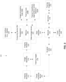
- FIG. 1 is a flowchart of a method of computing slide-level tissue type(s) for a tissue image of tissue extracted from a patient, in accordance with some embodiments of the present invention.
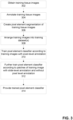
- FIG. 2 is a block diagram of components of a system 200 for computing slide-level tissue type(s) for a tissue image of tissue extracted from a patient and/or for training one or more classifiers for analysis of the tissue image, in accordance with some embodiments of the present invention.
- FIG. 2 is a block diagram of components of a system 200 for computing slide-level tissue type(s) for a tissue image of tissue extracted from a patient and/or for training one or more classifiers for analysis of the tissue image, in accordance with some embodiments of the present invention.
- FIG. 2 is a block diagram of components of a system 200 for computing slide-level tissue type(s) for a tissue image of tissue extracted from a patient and/or for training one or more classifiers for analysis of the tissue image, in accordance with some embodiments of the present invention
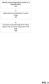
- FIG. 3 is a flowchart of an exemplary method for training a classifier for computing pixel element segmentation of a tissue image and/or patch(es) of the tissue image, in accordance with some embodiments of the present invention.
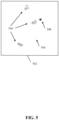
- FIG. 4 is a flowchart of some exemplary optional features of the method described with reference to FIG. 1 , in accordance with some embodiments of the present invention.
- System 200 may implement the acts of the method described with reference to FIG. 1 and/or FIG. 3 , optionally by a hardware processor(s) 202 of a computing device 204 executing code instructions stored in a memory 206.
- Computing device 204 may be implemented as, for example, a client terminal, a server, a virtual server, a laboratory workstation (e.g., pathology workstation), a procedure (e.g., operating) room computer and/or server, a virtual machine, a computing cloud, a mobile device, a desktop computer, a thin client, a Smartphone, a Tablet computer, a laptop computer, a wearable computer, glasses computer, and a watch computer.
- Computing 204 may include an advanced visualization workstation that sometimes is implemented as an add-on to a laboratory workstation and/or other devices for presenting indications of the analyzed tissue images and/or other computer added detections to the user (e.g. pathologist, interventional radiologist, oncologist, surgeon).
- the training of the neural network, and the analysis of tissue images by the trained neural network may be implemented by the same computing device 204, and/or by different computing devices 204, for example, one computing device trains the neural network, and transmits the trained neural network to a server device for analysis of tissue images.
- Computing device 204 receives 2D tissue images captured by an imaging device(s) 212.
- imaging device(s) 212 include: a scanner scanning in standard color channels (e.g., red, green blue), a multispectral imager acquiring images in four or more channels, a confocal microscope, and/or other imaging devices as described herein, a black a white imaging device, an imaging sensor.
- Imaging device(s) 212 creates tissue images from physical tissue samples obtained by a tissue extracting device 250, for example, a fine needle for performing FNA, a larger bore needle for performing a core biopsy, and a cutting tool (e.g., knife, scissors, scoop) for cutting out a sample of the tissue (e.g., tumor removal).
- a tissue extracting device 250 for example, a fine needle for performing FNA, a larger bore needle for performing a core biopsy, and a cutting tool (e.g., knife, scissors, scoop) for cutting out a sample of the tissue (e.g., tumor removal).
- a cutting tool e.g., knife, scissors, scoop
- Tissue extracting device 250 may be operated by a surgical robot 252, and/or manually by a user (e.g., physician, radiologist, oncologist, surgeon). Surgical robot 252 may be operated automatically, manually, and/or semi-automatically.
- a user e.g., physician, radiologist, oncologist, surgeon.
- Surgical robot 252 may be operated automatically, manually, and/or semi-automatically.
- surgical robot 252 operates tissue extracting device 250 to obtain additional tissue for generating additional tissue images by imaging device(s) 212, according to instructions generated by computing device 202 in response to analyzing previously obtained tissue images, as described herein.
- Training images 216 are used to train one or more of the classifiers (optionally CNNs), as described herein. It is noted that training images 216 may be stored by a server 218, accessibly by computing device 204 over network 210, for example, a publicly available training dataset, tissue images stored in a PACS server and/or pathology imaging server, and/or a customized training dataset created for training the classifiers, as described herein.
- Computing device 204 may receive the training images 216 and/or tissue images from imaging device 212 and/or image repository 214 using one or more imaging interfaces 220, for example, a wire connection (e.g., physical port), a wireless connection (e.g., antenna), a local bus, a port for connection of a data storage device, a network interface card, other physical interface implementations, and/or virtual interfaces (e.g., software interface, virtual private network (VPN) connection, application programming interface (API), software development kit (SDK)).
- a wire connection e.g., physical port
- a wireless connection e.g., antenna
- local bus e.g., a local bus
- a port for connection of a data storage device e.g., a data storage device
- network interface card e.g., other physical interface implementations
- virtual interfaces e.g., software interface, virtual private network (VPN) connection, application programming interface (API), software development kit (SDK)
- Hardware processor(s) 202 may be implemented, for example, as a central processing unit(s) (CPU), a graphics processing unit(s) (GPU), field programmable gate array(s) (FPGA), digital signal processor(s) (DSP), and application specific integrated circuit(s) (ASIC).
- Processor(s) 202 may include one or more processors (homogenous or heterogeneous), which may be arranged for parallel processing, as clusters and/or as one or more multi core processing units.
- Memory 206 (also referred to herein as a program store, and/or data storage device) stores code instruction for execution by hardware processor(s) 202, for example, a random access memory (RAM), read-only memory (ROM), and/or a storage device, for example, non-volatile memory, magnetic media, semiconductor memory devices, hard drive, removable storage, and optical media (e.g., DVD, CD-ROM).
- Memory 206 stores code instructions for implementing trained classifiers, detection code, and/or segmentation code 222A.
- Memory 206 stores image processing code 206A that implements one or more acts and/or features of the method described with reference to FIG. 1 and/or FIG. 4 , and/or training code 206B that executes one or more acts of the method described with reference to FIG. 3 .
- Computing device 204 may include a data storage device 222 for storing data, for example, one or more trained classifiers, detection code, and/or segmentation code 222A (as described herein), and/or training images 216.
- Data storage device 222 may be implemented as, for example, a memory, a local hard-drive, a removable storage device, an optical disk, a storage device, and/or as a remote server and/or computing cloud (e.g., accessed over network 210). It is noted that trained classifiers, detection code, and/or segmentation code 222A, and/or training images 216 may be stored in data storage device 222, with executing portions loaded into memory 206 for execution by processor(s) 202.
- Computing device 204 may communicate using network 210 (or another communication channel, such as through a direct link (e.g., cable, wireless) and/or indirect link (e.g., via an intermediary computing device such as a server, and/or via a storage device) with one or more of:
- network 210 or another communication channel, such as through a direct link (e.g., cable, wireless) and/or indirect link (e.g., via an intermediary computing device such as a server, and/or via a storage device) with one or more of:
- imaging interface 220 and data interface 224 may exist as two independent interfaces (e.g., two network ports), as two virtual interfaces on a common physical interface (e.g., virtual networks on a common network port), and/or integrated into a single interface (e.g., network interface).
- image analysis code including one or more of: classifier code, and/or detection code, and/or segmentation code is provided and/or trained.
- Each instance of the image analysis code may be trained to process a certain type of tissue image, for example, according to one or more of the following: medical procedure being performed, image colors, image resolution, tissue type expected to be included in the tissue image, histology or cytology, and clinical indication.
- the instances of the image analysis code may be selected from multiple available types of image analysis code.
- the selection may be performed manually by the user (e.g., via the GUI, for example, via a menu and/or icons of available image analysis code).
- the selection may be performed automatically by code that analyzes, for example, the tissue image, metadata of the image, and/or other patient data associated with the image such as procedure being performed (e.g., obtained from a PACS server, DICOM data, and/or electronic medical record).
- the types of image analysis code may be implemented as, for example, neural network (NN), such as fully connected NN, convolutional NN, full convolutional NN, and/or a combination of multiple sub-architectures, for example, integrated networks, parallel networks, and/or cascade networks.
- NN neural network
- Some image analysis code may output intermediate results, for example, a heatmap, which other types of image analysis codes may process further.
- other machine learning methods may be used, for example, support vector machine, clusterization methods, sets of rules, and decision trees.
- tissue is obtained.
- the tissue may be obtained intra-operatively, during for example, a biopsy procedure, a FNA procedure, a core biopsy procedure, colonoscopy for removal of colon polyps, surgery for removal of an unknown mass, surgery for removal of a benign cancer, and/or surgery for removal of a malignant cancer.
- Tissue may be obtained from fluid, for example, urine, synovial fluid, blood, and cerebral spinal fluid.
- Tissue may be obtained by using the tissue extracting device.
- Tissue may be obtained by the surgical robot operating the tissue extracting device.
- Tissue may be in the form of a connected group of cells, for example, a histological slide. Tissue may be in the form of individual or clumps of cells suspended within a fluid, for example, a cytological sample.
- tissue is processed for imaging.
- the tissue image created from the physical slide with tissue thereon is a color image, optionally including multiple channels for each pixel, for example, 3 (e.g., RGB) or more channels (e.g., multispectral, confocal).
- the tissue image is created based on visible light energy. For example, capturing a digital image of a view as seen under a light microscope.
- the tissue may be arranged on a slide.
- a frozen section may be created and sliced for creating multiple slides.
- Tissue may be stained.
- the slides may include histology slides and/or cytology slides.
- the tissue may be chemically stained for increased visibility for generation of the tissue image.
- the staining process takes additional time.
- the tissue itself is not stained, but rather imaging methods are used that do not necessarily requiring staining, for example, a spectral imager.
- a set of colors associated with the chemical staining and/or virtual staining is identified.
- the set of colors may be stored, for example, in a dataset according to the chemical staining and/or virtual staining.
- the set of colors may be automatically identified by code and/or manually designated by the user according to the chemical and/or virtual staining.
- the identified set of colors may be used for segmenting tissue versus non-tissue background, and/or for selecting the type of image analysis code, as described herein in additional detail.
- the identified set of colors may be stored, for example, in a LAB color space, RGB color space, and/or other color spaces. It is noted that LAB color space is more linear than RGB color space.
- a tissue image is created by imaging the tissue by the imaging device.
- slides including the prepared tissue are imaged by the imaging device.
- the tissue slides are imaged at high magnification, for example, between about X200 - X400, or about X100-400, or about X100-X200, or about X100, or about X200, or about X400, or other values.
- high magnification imaging may create very large images, for example, on the order of Giga Pixel sizes.
- Such large tissue images of the entire slide may be referred to herein as Whole Slide Images (WSI).
- the imaging device may be implemented as, for example, a spectral imager, such as a multispectral (few to tens of channels) or a hyperspectral (up to hundreds of channels).
- the multispectral imager creates tissue images with 4 or more spectrum frequencies, which is noted to be higher than the 3 spectrums of a normal imager (e.g. imaging in red, green, and blue (RGB).
- the imager may produce a spectral signature including multiple channels for each pixel, in contrast for example, to the 3 channels (e.g., RGB) obtained by the traditional staining process.
- the image analysis code described herein may be created and/or trained according to the spectral signature of each pixel. It is noted that alternatively, a standard imager imaging in 3 channels (e.g., RGB) may be used, and/or a black and white imager may be used.
- the image is implemented based on a Stimulated Raman scattering (SRS) microscopy.
- SRS Stimulated Raman scattering
- the spectral image (cube) acquired by a spectral imager, or a SRS microscope, may be analyzed by combining morphological based method with spectral based methods to improve the outcome of traditional image analysis methods relying purely on RGB images.
- a mapping and/or other transformation function is estimated between the colors (e.g., RGB) of an image of stained tissue and the spectrum corresponding to the same location.
- the mapping may be used to produce a virtual stained slide from a spectral image of a fresh tissue slide.
- the tissue image of the tissue extracted from the body of the patient is provided.
- Multiple tissue images of the tissue may be provided, for example, from the same biopsy, of different stains, of the same body fluid, and slices from a sequential slicing (e.g., frozen section).
- the multiple tissue images may be arranged as a single 3D tissue image, and/or as a set of 2D slices.
- the multi-slide level tissue type(s) may be computed according to an analysis of the multiple tissue images, as described herein.
- the tissue images may be obtained, for example, from a PACS server, an EMR server, from the imaging device that captured the tissue image from the physical slide that included the tissue extracted from the patient, and/or from a storage device (e.g., portable storage medium, storage server).
- tissue images are automatically sent to analysis after capture by the imager and/or once the images are stored after being scanned by the imager.
- the tissue image also referred to as the WSI, is segmented, for example, by segmentation code stored as code instructions in a memory executable by the hardware processor(s) of the computing device.
- the tissue image includes tissue portions indicative of the physical tissue obtained from the patient, and non-tissue background (e.g., empty space on the slide), and/or noise (e.g., color markers such as made by a pen, out-of-focus areas, dirt on the slide). It is noted that noise may be due to tissue which cannot be adequately analyzed, for example, out-of-focus areas, and/or may be due to non-tissue elements such as dirt.
- the segmentation of the tissue is performed for segmenting tissue objects from the tissue image, for example, cells such as normal cells, cancer cells, pre-cancer cells, cells of the organ, immune system cells, and bacteria.
- the tissue objects represent portions of the tissue image for further analysis.
- the segmentation may be performed for exclusion of the background and/or noise.
- tissue image patches are created from the tissue image. It is noted that patches may be created as part of the segmentation process described herein. Alternatively, the patches for segmentation are different than the patches created for further analysis.
- Patches may be created according to the design of the image analysis code, for example, at a predefined size and/or predefined resolution according to the size and/or resolution of training images used to train the image analysis code. Patches may overlap, for example, about 10%, or 25%, or 50%, or other values.
- the resolution and/or patch size may be selected according to clinical indication, for example, when looking for bacteria, the size of each patch may be relatively small with high resolution, to enable identifying the small bacteria.
- the patch-level segmentation code may be implemented as a segmentation CNN (e.g., based on Unet).
- the patch-level segmentation may output the segmentation as a mask.
- the patch-level segmentation code may be trained according to patches that are annotated with segmentation markings.
- the patch-level classification CNN is trained according to a training dataset of patches from tissue images (i.e., WSIs) from known tissue types of sample individuals.
- the patches may be manually annotated by a user (e.g., via the GUI) and/or automatically annotated (e.g., according to data extracted from the EMR of the patient indicating the diagnosis and/or procedure performed).
- the patches may be obtained from segmented patches identified as including tissue objects, as described herein. Patches may be obtained at different resolutions, for example, x40, x100, or other values.
- the patches and associated annotation indicative of tissue type are used to train the CNN to output tissue type(s) for a new inputted patch.
- tissue type is bacteria.
- An example of a sub-type of bacteria is Helicobacter pylori.
- tissue type is cell.
- An example of a sub-type of cell is neutrophils.
- the patches are analyzed as a whole tissue image, according to one or more of: the classified tissue type(s), the associated relative location of the respective patch, and the segmentation of the respective patch.
- the analysis is performed by slide-level analysis code, which may be stored in the memory and executable by hardware processor(s) of the computing device.
- one or more slide-level tissue types are computed for the tissue image as a whole according to the analysis of the patches.
- the slide-level tissue type(s) may be computed according to the patch-level tissue type(s), optionally according to the relative location of the respective patches within the tissue image.
- the slide-level tissue type may be, for example, an overall diagnosis made for the tissue slide as a whole. For example, malignancy, a benign tumor, a certain disease, or normal tissue.
- the slide-level tissue type may be a quantification of various aspects, for example, Ki67 positive nuclei ratio.
- computing the slide-level tissue type for example, a final slide-level diagnosis
- the computation of the slide-level tissue type may be based on cross patch analysis, optionally according to the position of the patches relative to one another. Complexity of computation of the slide-level tissue type arises, for example, due to small errors in the computed patch-level results. When the tissue image is divided into approximately thousands of patches, a very small error percent may lead to some false patch identifications, which when left unchecked may be propagated to errors in the slide-level tissue type. Computation of the slide-level tissue type is designed to account for such patch-level errors, and/or optionally remove such patch-level errors.
- the relative location of the analyzed patches affects the slide-level tissue type, for example, in making a final diagnosis.
- tissue of "High Grade Adenoma” and “Malignancy” have the same visual representation in the patch level, and cannot be differentiated at the patch level.
- the determination whether the slide-level tissue type is "High Grade Adenoma” or "Invasive Carcinoma (Malignant)" depends on whether the identified tissue has invaded beyond muscularis mucosa into submucosa, which requires an analysis of the relative location of the identified patches to reach the final slide-level tissue type.
- the received indication may be computed by detection code that automatically detects the tissue type(s) according to: tissue object(s) of the certain tissue type in the patch(es), patch(es) classified as the certain tissue type, and/or a segmentation of tissue objects of the certain tissue type above a predefined threshold number of pixels of the patch(es) of the tissue image segmented as the certain tissue type.
- tissue object(s) of the certain tissue type in the patch(es) patch(es) classified as the certain tissue type
- a segmentation of tissue objects of the certain tissue type above a predefined threshold number of pixels of the patch(es) of the tissue image segmented as the certain tissue type For example, for the received indication of polyp, exemplary potential slide-level type type(s) include: hyperplastic, low grade adenoma, high grade adenoma, and malignant.
- the slide-level tissue type(s) include slide-level sub-tissue type(s), for example, for slide-level tissue type of Adenomatous Lesion, potential sub-tissue type(s) include tubular, tubulovillous, and villous.
- exemplary potential slide-level type type(s) include: gastritis (e.g., type of gastritis such as chronic or acute), amount of Helicobacter Pylori bacteria (e.g., none, few, many), and presence of dysplasia.
- low grade adenoma is computed as the slide-level tissue type when more than a predefined number and/or percent of patches are computed with patch-level tissue type of low grade adenoma, and no patches are computed with patch-level tissue type of a higher diagnosis.
- a multi-slide level tissue type(s) is computed for multiple tissue images, and/or for a 3D tissue image.
- the multiple slides and/or 3D tissue image may be produced, for example, from the same biopsy, and/or same target tissue (e.g., slices of frozen section), and/or from the same sample of body fluid.
- the slides may be created with the same stain, or from different stain types, where different processes are used to analyzing the tissue images created from different stain types.
- a slide-level tissue type e.g., per-slide diagnosis
- per-slide diagnosis may be computed as described with reference to act 118.
- the multi-slide level diagnosis (e.g., biopsy level analysis, frozen section level analysis, body fluid level analysis) may be performed according to the slide-level analysis and/or slide-level tissue type(s), using multiple slides. Alternatively or additionally, the multi-slide level analysis is performed according to the patch-level tissue type(s) (e.g., as described with reference to act 114) and/or analysis of patches (e.g., as described with reference to act 116).
- the multi-slide level analysis may be performed according to one or a combination of the following exemplary processes:
- the set of rules may define an indication of adequacy of the tissue image.
- Exemplary sets of rules include: blurry tissue image, poor sample preparation, unclean margins, identified tissue does not correspond to target biopsy location, insufficient tissue for proper classification, and no malignancy detected (e.g., in the sentinel lymph node, in the tissue, in the fluid), abnormal patches and/or tissue object(s) to make diagnosis, insufficient cells are present to make a proper diagnosis, and/or when incorrect cells are present which are different than expected cells.
- the set of rules is met, meaning the tissue image is adequate, the generate instructions may be to stop any further treatment.
- the generated instructions include instructions for additional treatment of the patient.
- the additional treatment of the patient includes additional treatment to obtain another tissue sample from the patient.
- the acts of the method described with reference to FIG. 1 are iterated for analysis of the another tissue image of the another tissue sample.
- the analysis of the additional tissue image may be compared to the previous analysis (e.g., to determine whether the same problem remains or whether a new problem arose and/or whether an improvement has been obtained), and/or the analysis may be performed independently for each tissue image.
- the GUI is updated for presentation of the computed slide-level tissue type(s) and/or multi-slide level tissue type(s).
- the GUI is designed to present tissue images and/or patches of the tissue image and/or the registered slide(s) and/or the 3D tissue image.
- the GUI presents computed results described herein, for example, segmentation of tissue objects, classification results of tissue type(s) per patch and/or slide-level tissue type(s).
- the GUI may present a generated report, which may be based on a pathology template.
- the GUI may include features for easy navigation between the different patches of the tissue image, and/or for navigation of the computed results.
- GUI graphical user interface
- audio may be played over speakers
- email may be generated and sent to a client terminal
- video may be generated and played
- text may be generated and presented
- pop-up window may be displayed.
- the GUI may include a feature for adjusting the computed results and/or approving the computing results.
- the GUI may present regions (e.g., patches) of the tissue image for further manual investigation by a user, for example, according to classified and/or detected and/or segmented patches and/or tissues objects, which may be defined according to a set of rules, for example, tissue objects classified as bacteria, and patches with abnormal tissue objects, and patches classified as including malignant cells.
- the GUI may include a feature for selection of a patch, for which similar patches are found, as described with reference to act 402 of FIG. 4 . Similar patches with similar metadata and/or annotations (e.g., ground truth, diagnosis) may be grouped together.
- the GUI may include a feature for presenting the entire tissue image associated with one or more of the matched similar patches. The location of the matched similar patch may be marked relative to the whole tissue image, for example, with a rectangle having dashed borders.
- the GUI may present the identified abnormal regions and/or tissue object(s) described with reference to act 404 of FIG. 4 .
- the abnormal regions and/or tissue object(s) may be marked within the presented patch and/or within the presented tissue image, for example, with a polygon having dashed borders.
- the instructions for further treatment of the patient, or to avoid further treatment may be presented within the GUI. For example, as a text message, played as an audio file, and/or a video may be shown instructing the user on what to do in the next treatment to obtain a proper tissue sample (e.g., proper FNA practices).
- the GUI may be dynamically updated in response to additional tissue images of additional tissue samples obtained according to previous instructions. Exemplary instructions include: obtain another tissue sample from same location, obtain another tissue sample from another location, obtain another tissue sample at a defined location, and unclean surgical margins - excise additional tissue.
- a video is played showing different regions (e.g., patches) of the tissue image used to determine the slide-level tissue type.
- FIG. 6 is a schematic of an exemplary GUI 602 presenting a list of automatically analyzed tissue images, in accordance with some embodiments of the present invention.
- Cases may be sorted and/or filtered according to a menu 604, for example, per specific case, according to organ from where the tissue was obtained, according to urgency of the procedure, according to treatment status, and/or according to date.
- Window 606 presents an example of a case, including, for example, patient demographic data, procedure performed (e.g., gastric biopsy to rule out HP), and results of the automated analysis (e.g., Gastritis: Chronic Active, and HP).
- the user may select a certain case to obtain additional details, for example, view the tissue image, view the patches, view the automated report, and/or other computed results.
- Red regions marked by 812 may be indicative of another probability range (e.g, 51-100%), or may be indicative of another patch-level tissue type computed for the corresponding patch(es).
- GUI 802 may present the computed slide-level tissue type(s) 814 (e.g., LG Dysplasia).
- FIG. 9 is a schematic of an exemplary GUI 902 presenting a computed segmentation shown in association with a heatmap 906, along with detection results 908, in accordance with some embodiments of the present invention.
- the region covered by heatmap 906 may denote the segmentation of the tissue objects, Helicobacter Pylori bacteria in the present case. Colors of heatmap 906 may be indicative of, for example, the probability of each pixel denoting the Helicobacter Pylori bacteria, for example, red denoting relatively high probability and blue denoting relatively lower probability.
- Detection results 908 may indicate the detected location of Helicobacter Pylori bacteria, for example, shown as a square with dashed lines. Detection results 908 may be computed, for example, per patch. Detection results 908 may be computed by detection code, and/or the classifier code.
- Results 1004 may include, for example, the slide-level tissue type (e.g., diagnosis), and/or patch-level tissue type (e.g., of the detected tissue object(s)). Results 1004 may be adjusted by the user, and/or approved for automatically generating the report.
- the slide-level tissue type e.g., diagnosis
- patch-level tissue type e.g., of the detected tissue object(s)
- one or more acts 102-122 are iterated, for dynamically updating the GUI. For example, another tissue sample is obtained when the current tissue sample is inadequate, another tissue image may be created and analyzed, as described herein. The GUI is updated according to the new tissue image.
- training tissue images are obtained for multiple sample individuals.
- the training tissue images may be of different tissue types, for example, obtained by different procedures, of different organs, of different body fluids, and/or obtained for different clinical indications.
- the tissues images are annotated.
- the annotation may be obtained from pre-stored data, for example, a pathology report, a diagnosis code, and/or other data stored in the patient medical record.
- the annotation may be manually performed by a user.
- Each tissue image is annotated at the slide-level with a slide-level tissue type, and/or at the pixel element level.
- the pixel element level annotation may be, for example, a segmentation of tissue object(s) with an associated tissue type assigned to the segmented region.
- one or more patches and/or tissue images segmented at the pixel element level are created by a user via the GUI.
- the user may start from an unannotated patch of a tissue image, where the tissue image is unannotated, or annotated at the slide-level.
- the user delineates one or more pixel elements indicative of a tissue object denoting a certain tissue type, for example, by manually marking a border around the tissue object.
- the border may be marked using the GUI, for example, a freeform line drawn around the tissue object, a polygon drawn around the tissue object, and/or a rectangle drawn to include the tissue object therein.
- the user may select individual pixel elements, and/or groups of pixel elements by marking the border around the group of pixel elements (e.g., polygon, rectangle). For example, the user selects each bacteria in the image and/or patch, and/or selects nuclei of a certain type.
- the user may manually enter the tissue type to associate with the selected pixel element.
- the tissue object is segmented by segmentation code, for example, all pixel elements within the defined region are segmented. Pixel elements of the segmented tissue object are designated as indicative of the certain tissue type.
- the patch with annotated segmented tissue object is stored in the sub-set of training images having pixel element level annotation.
- training images may be arranged into one or more training datasets for training classifiers and/or segmentation code for computing patch-level tissue type(s).
- Training dataset may be organized, for example, according to tissue types, according to procedure type, according to target organs from which the tissue sample was extracted, according to body fluid, and/or according to clinical indications.
- a pixel element level classifier optionally implemented as a CNN, is trained.
- the pixel element level classifier is trained according to the sub-set of training images that include pixel element level annotation.
- the pixel element classifier may be used as the segmentation code and/or detection code described herein (e.g., with reference to the process of FIG. 1 and/or FIG. 4 ), for segmentation and/or detection of tissue object(s) in patches.
- the pixel element level CNN is further trained according to patches created from each training image of another sub-set of training images that include slide-level annotation.
- the other sub-set of training images do not include pixel level annotations.
- patches of the training images that include slide-level annotations are selected for the training. Patches may be selected manually by a user, and/or may be automatically selected, for example, all patches are selected, or patches with pixels indicative of objects other than background are selected (i.e., patches with only background are excluded).
- the pixel element level CNN is trained according to a loss function based on distance to a certain patch of the patches of each training image that includes slide-level annotation, associated with highest probability of belonging to the slide-level tissue type of the tissue image from which the certain patch is extracted.
- the initial probabilities of belonging to the slide-level tissue type(s) of the tissue image associated with the certain patch are computed by the trained pixel element level CNN.
- the initial probabilities are adjusted according to the loss function.
- the classifier and/or segmentation code may be trained based on multiple instance learning (MIL) approaches.
- MIL training approaches are based on diving the slide-level annotated tissue image into multiple patches (referred to as bags), where a model is trained for all patches.
- the loss function of the model during training is based on the slide-level annotation, according to the distance to the patch with the highest probability of belonging to the category of the slide-level annotation.
- the CNN is trained, optionally simultaneously and/or during the same training round(s), using both training images with pixel-level annotation and training images with slide-level annotation.
- the ground truth used for training the CNN is indicated according to a location of a respective patch of the sub-set of training images including the pixel element level tissue type(s), and according to the sub-set of images with slide-level tissue type annotation, wherein only patches with highest probability above a threshold indicative as belonging to the slide-level tissue type according to the CNN are considered for training the CNN.
- the trained pixel element classifier code is provided, for example, stored in memory and/or the data storage device of the computing device.
- the pixel element classifier may be stored as the segmentation code and/or detection code described herein (e.g., with reference to the process of FIG. 1 and/or FIG. 4 ), for segmentation and/or detection of tissue object(s) in patches.
- act 402 relates to identifying one or more tissue image patches that are similar to a selected patch of the tissue image.
- the similar tissue image patches are obtained from a dataset storing tissue images acquired for other sample individuals.
- Act 402 may be executed, for example, after and/or simultaneously with one or more acts 112-124 of FIG. 1 .
- Act 404 relates to detecting abnormal patches in the tissue image.
- Act 404 may be executed, for example, after and/or simultaneously with one or more acts 112-124 of FIG. 1 .
- Act 406 relates to comparing the computed slide-level tissue type(s) with a manual diagnosis. Act 406 may be executed, for example, after and/or simultaneously with one or more acts 118-124 of FIG. 1 .
- another patch from another tissue image of another patient that is similar to one of the patches of the tissue image of the patient is identified.
- the similar patch may be identified, for example, for training purposes (e.g., showing other similar cases to students learning to analyze histology slides), and/or for diagnosis purposes (e.g., in a difficult case, presenting results of previously similar patches to aid the user in determining the diagnosis for the current case)
- a patch is selected from the tissue image, optionally via the GUI, for example, the user may click on one of the patches computed from the tissue image and/or click on a certain pixel element where the patch associated with the pixel element is selected, and/or may create their own patch by marking an outline on the tissue image (e.g., a mark a polygon).
- An encoding (which may sometimes be substituted with the term embedding ) is computed for the selected patch by a trained autoencoder code, optionally an autoencoder CNN. The encoding may be stored as a feature vector.
- One or more similar patches are identified from a dataset of patch encodings, according to a requirement of a similarity distance between the encoding of the selected patch and encoding of the patches in the dataset.
- the similarity distance may be computed, for example, by considering each encoding as a point in a multidimensional space and computing the distance between the points in the multidimensional space, a correlation function that computes a correlation value, and/or other methods.
- the threshold may be defined by the user, set as a predefined value, and/or computed by code. The threshold may be dynamically adjusted. A set of one or more (e.g., multiple) similar patches is identified.
- the matching similar patch(es) may be presented in the GUI.
- the identified patch(es) are presented in association with previously analyzed results, for example, tissue types seen in the patch(es), overall diagnosis for the tissue image from which the slide was taken, procedure used to obtain the patch, and data of the patient from which the tissue for the patch was extracted.
- the similar patch(s) may be presented alongside the current patch.
- the matches may be grouped together for presentation in the GUI.
- a similarity score indicative of similarity between the matching patches and the selected patch may be computed and presented. The similarity score may be computed according to the similarity distance.
- the autoencoder CNN may be trained according to different tissue images of different tissue types obtained for different sample patients.
- the patches are labeled with a ground-truth indicative of tissue type(s).
- the annotation of tissue type may be performed manually by the user, extracted from the EMR (e.g., pathology report), and/or computed as described herein.
- the autoencoder CNN is trained on patches of each tissue image (i.e., WSI), optionally after tissue objects are segmented.
- the loss function for training the autoencoder CNN may denote a reconstruction error between the original respective patch of the tissue mage and the corresponding decoded patch.
- the dataset of patch encodings stores the encoding of each patch computed by the autoencoder CNN, optionally as a feature vector.
- the dataset may store the image of the patch and/or metadata associated with the patch (e.g., ground-truth tissue type(s), data of the slide, location of the patch within the tissue image) in association with the encoding of the patch.
- abnormal patches are detected.
- abnormal tissue objects within patches are detected.
- Such abnormal patches and/or tissue objects are indicative of tissue regions where the tissue type(s) cannot be computed, and/or where the probability indicative of the computed tissue type(s) is below a threshold. For example, a diagnosis cannot be made due to the abnormal patches.
- Such abnormal areas may be flagged for manual inspection by a specialist. The specialist may spend more time inspecting the abnormal areas, which overall saves time in analyzing the tissue image.
- a first exemplary process for detecting abnormal patches and/or abnormal visual object(s) in patches is now described. The process is based on determining that the patch and/or tissue object is abnormal according to a statistical distance to the dataset of encoded patches indicative of abnormality.
- the dataset of encoded patches is described with reference to act 402.
- the autoencoder CNN computes an encoding for each patch of the tissue image, optionally after tissue segmentation is performed as described herein.
- the autoencoder CNN is trained according to patches identified as not abnormal, and/or normal, for example, as described with reference to act 402. It is noted that what is considered normal may vary according to clinical context.
- the clinical context may be stored in association with the normal patches, for example, as metadata.
- the patches may be clustered by clusterization code.
- the cluster centroids may be stored in the dataset.
- a statistical distance is computed between each encoding of each patch of the tissue image and the patch encodings stored in the dataset.
- the statistical distance is computed between the encoding of each patch of the tissue image and the cluster centroids and/or the encoded patches stored in the dataset.
- One or more patches are identified as abnormal when the statistical distance between the respective patch and one or more nearest encoding of patches denoting normal tissue is above an abnormality threshold.
- the abnormality threshold may be computed by computing a similarity distance function between encodings of patches determined to be normal (e.g., manually by a user) and the most similar normal encoded patch(es) stored in the dataset (e.g., most similar patches may be found as described with reference to act 402), for example, the sum of the closest distances, the median of the closest distances, the average of the closest distances.
- An abnormality distance is computed between encodings of patches determined to be abnormal (e.g., manually by a user) and the most similar normal encoded patch(es) stored in the dataset.
- the abnormality threshold is determined as to how close the normal patches are to other normal patches in the dataset (and/or to cluster centers of normal patches), and still be considered normal.
- the abnormality threshold may be set such that a certain percentage (optionally all, or about 90%, or about 95%) of normal patches have distances below the abnormality threshold, and a certain percentage (optionally all, or about 90%, or about 95%) of abnormal patches are above the abnormality threshold.
- the actual value of the abnormality threshold may be computed according to the values of the computed distances.
- the abnormality threshold may be set according to a desired tradeoff between specificity and sensitivity, for example, according to clinical case.
- the abnormality threshold may be set, for example, manual by the user, obtained from a stored predefined value such as according to clinical indication, and/or automatically computed.
- the abnormality threshold may be dynamically adjusted.
- a second exemplary process for detecting abnormal patches and/or abnormal visual object(s) in patches is now described. The process is based on determining that the patch and/or tissue object is abnormal according to a comparison to other patches and/or tissue objects of the tissue image.
- the patches of the tissue image are clustered.
- each patch is passed through the autoencoder CNN and the encodings are clustered, for example, by clusterization code.
- the autoencoder CNN is either pre-trained using normal patches, or based on the patches in the current slide training is performed.
- a distance is computed between each patch encoding and one or more of the cluster centers.
- the distance is between the patch encoding and the center of the cluster associated with the patch.
- One or more patches are identified as abnormal when the statistical distance between the encoding of the respective patch and the cluster center is above an abnormality threshold.
- patches located a certain distance away from the center(s) of the cluster(s) are determined to be abnormal.
- the furthest predefined percentage of patches e.g., 1-5%, or other values
- one or more clusters located furthest away (e.g., and/or above an abnormality threshold) from the other clusters e.g., according to cluster centers) are identified as being abnormal.
- the patches of the abnormal cluster(s) are identified as being abnormal.
- patches located furthest away (e.g., and/or above an abnormality threshold) from other patches are identified as being abnormal.
- a third exemplary process for detecting abnormal patches and/or abnormal visual object(s) in patches is now described.
- the third exemplary process is based on classification consistency by a trained classifier that is dynamically adjusted during each classification iteration of the same patch.
- Each patch of the tissue image is inputted into a trained patch classifier, optionally a CNN.
- the patch classifier computes a probability of likelihood of tissue type(s) for the patch.
- the patch classifier is trained according to patches labeled with tissue type, which may include normal tissue type and/or abnormal tissue types.
- the same patch is iteratively inputted into the trained patch classifier multiple times, where each time the patch classifier is adjusted, optionally randomly, for example, one or more neurons are dropped (e.g., ignored, excluded) from the CNN.
- the computed probability of tissue type(s) of the multiple iterations are analyzed.
- An indication of likelihood of abnormality is computed for the patch when the analysis of the probabilities of tissues types varies according to a consistency requirement.
- the computed slide-level tissue type(s) is automatically compared to a manual diagnosis of the slide.
- An alert is generated when a mismatch is detected, for example, presented in the GUI, sent as an email, stored as an event for future viewing, sent as a message to a mobile device, and/or a pop-up window on an administrative server.
- the manual diagnosis may be obtained, for example, from metadata associated with the tissue image, from a pathology report, from the electronic medical record of the patient, and/or manually entered.
- the manual diagnosis may be made by a user (e.g., pathologist) based on standard methods.
- the manual diagnosis may be stored, for example, as free text, and/or a predefined diagnostic code.
- FIG. 11 is an exemplary flowchart of possible dataflow implementations based on the methods described with reference to FIGs. 1 , 3 , 4 , and/or executable by components of system 200 described with reference to FIG. 2 , in accordance with some embodiments of the present invention.
- tissue segmentation 1102 to exclude background and/or noise (e.g., as described with reference to act 110 of FIG. 1 ), followed by a tissue type detection feature 1104 to identify the overall tissue being analyzed (e.g., as described with reference to act 114, and/or 118 of FIG. 1 ).
- Abnormality flow 1106 includes an abnormality detection feature 1108 for detecting abnormal tissue object(s) in the segmented tissue, for example, as described with reference to act 404 of FIG. 4 .
- Annotation and Training Flow 1110 includes an annotation feature 1112 for manual annotation of tissue objects, and/or a feature 1114 for training analysis code such as a classifier, segmentation code, and/or detection code, with weak (i.e., slide-level) and strongly (i.e., per pixel element level) annotated data.
- Annotation feature 1112 is described, for example, with reference to act 304 of FIG. 3 .
- Training feature 1114 is described, for example, with reference to acts 306-312 of FIG. 3 .
- Interference flow 1116 is for inferring the image type to compute the slide-level tissue type(s), for example, overall diagnosis.
- Inference flow 1116 includes a feature 1118 for patch level detection and/or segmentation (e.g., as described with reference to act 110,112, and/or 114 of FIG. 1 ), a feature 1120 for patch level classification (e.g., as described with reference to act 114 of FIG. 1 ), a feature 1122 for computational of the slide-level tissue type(s) such as diagnosis (e.g., as described with reference to act 118 of FIG.
- the slide-level tissue type(s) e.g., diagnosis
- a manual physician diagnosis e.g., as described with reference to act 406 of FIG. 4
- a feature 1126 for presenting the results in the GUI e.g., as described with reference to act 122 of FIG. 1 ).
- Similarity flow 1128 includes a feature 1130 for searching for patches that are similar to a selected path, as described for example, with reference to act 402 of FIG. 4 .
- Abnormality flow 1106, annotation and training flow 1110, interference flow 1116, and similarity flow 1128 process patches extracted from the tissue image, described, for example, with reference to act 112 of FIG. 1 .
- tissue image is intended to include all such new technologies a priori.
- composition or method may include additional ingredients and/or steps, but only if the additional ingredients and/or steps do not materially alter the basic and novel characteristics of the claimed composition or method.
- a compound or “at least one compound” may include a plurality of compounds, including mixtures thereof.
- range format is merely for convenience and brevity and should not be construed as an inflexible limitation on the scope of the invention. Accordingly, the description of a range should be considered to have specifically disclosed all the possible subranges as well as individual numerical values within that range. For example, description of a range such as from 1 to 6 should be considered to have specifically disclosed subranges such as from 1 to 3, from 1 to 4, from 1 to 5, from 2 to 4, from 2 to 6, from 3 to 6 etc., as well as individual numbers within that range, for example, 1, 2, 3, 4, 5, and 6. This applies regardless of the breadth of the range.
Landscapes
- Engineering & Computer Science (AREA)
- Physics & Mathematics (AREA)
- Theoretical Computer Science (AREA)
- General Physics & Mathematics (AREA)
- Health & Medical Sciences (AREA)
- General Health & Medical Sciences (AREA)
- Computer Vision & Pattern Recognition (AREA)
- Biomedical Technology (AREA)
- Data Mining & Analysis (AREA)
- Life Sciences & Earth Sciences (AREA)
- Molecular Biology (AREA)
- Software Systems (AREA)
- Medical Informatics (AREA)
- General Engineering & Computer Science (AREA)
- Evolutionary Computation (AREA)
- Artificial Intelligence (AREA)
- Mathematical Physics (AREA)
- Biophysics (AREA)
- Computing Systems (AREA)
- Computational Linguistics (AREA)
- Multimedia (AREA)
- Public Health (AREA)
- Quality & Reliability (AREA)
- Nuclear Medicine, Radiotherapy & Molecular Imaging (AREA)
- Radiology & Medical Imaging (AREA)
- Probability & Statistics with Applications (AREA)
- Primary Health Care (AREA)
- Epidemiology (AREA)
- Pathology (AREA)
- Databases & Information Systems (AREA)
- Bioinformatics & Cheminformatics (AREA)
- Bioinformatics & Computational Biology (AREA)
- Evolutionary Biology (AREA)
- Image Analysis (AREA)
- Investigating Or Analysing Biological Materials (AREA)
- Magnetic Resonance Imaging Apparatus (AREA)
Claims (11)
- Computerimplementierte Verfahren zur Berechnung mindestens ein Objektträger-Gewebetyp für das Gewebebild eines Gewebes, das aus einem Patienten extrahiert wurde, umfasst:Empfangen eines Gewebebildes von einem Objektträger, der ein aus dem Patienten extrahiertes Gewebe umfasst (108);Segmentieren der Gewebeobjekte des Gewebebildes (110);Erstellen einer Vielzahl von Gewebebild-Patches aus den segmentierten Gewebeobjekten des Gewebebildes (112);Klassifizieren, durch einen Patch-Level-Klassifizierer, jedes der mehreren Gewebebild-Patches in mehrere Patch-Level-Gewebetypen, wobei jeder der klassifizierten Gewebebild-Patches mit einer relativen Position innerhalb des Gewebebildes (114) verbunden ist;wobei der Patch-Level-Klassifizierer Ausgänge, für jedes jeweilige Patch, einen Vektor erzeugt, der mehrere Wahrscheinlichkeiten speichert, wobei jede der mehreren Wahrscheinlichkeiten anzeigt, dass das jeweilige Patch in eine der mehreren Patch-Level-Gewebetypen (114) klassifiziert ist;Analysieren, durch einen Objektträger-Analysecode, der klassifizierten mehreren Patch-Level-Gewebetypen und der zugehörigen relativen Position für jeden der mehreren Gewebebild-Patches des durch den Patch-Level-Klassifikator (116) ausgeben werden, um mindestens einen Objektträger-Gewebetyp für das Gewebebild (118) zu berechnen ; undmindestens einen Objektträger-Gewebetyp bereitzustellen, undwobei der Objektträger-Analysecode ein neuronales Faltungsnetz (CNN) umfasst, das als Ausgang ein Bild erhält, in dem jedes Pixel die Ausgabe des Patch-Level-Klassifizierers für den entsprechenden Patch in dem Gewebebild speichert; undwobei das CNN trainiert wird, einen oder mehrere Objektträger-Gewebetypen in Abhängigkeit von der mehreren Patch-Level-Gewebetypen zu berechnen.
- Verfahren nach Anspruch 1, wobei mindestens ein Objektträger-Gewebetyp von den mehreren Patch-Level-Gewebetypen (118) unterscheidet.
- Verfahren nach Anspruch 1, wobei dem mindestens ein Objektträger-Gewebetyp auf der Grundlage von zwei oder mehr unterschiedlichen Patch-Level-Gewebetypen berechnet wird, die für zwei oder mehr Patch (118) berechnet wurden.
- Verfahren nach Anspruch 1, wobei die zugehörige relative Lage von der Lage den Patches des extrahierten Gewebes abhängt, die sich auf dem Objektträger befinden, und relative in-situ anatomische Lagen innerhalb des Körpers des Patienten ausschließt.
- Verfahren nach Anspruch 1, wobei eine mehreren von Gewebebildern von einer mehreren Objektträgern sequentieller Schnitte des aus dem Patienten extrahierten Gewebes empfangen wird, wobei die mehreren Gewebebildern aufgezeichnet wird, um ein einzelnes aufgezeichnetes Gewebebild zu berechnen, wobei die Pixelwerte des einzelnen aufgezeichneten Gewebebildes auf der Grundlage der Pixelwerte der aufgezeichneten Gewebebilder berechnet werden, wobei die Segmentierung, die Erzeugung der mehreren Gewebebild-Patches, die Klassifizierung, die Analyse und die Bereitstellung für das einzelne aufgezeichnete Gewebebild durchgeführt werden, um mindestens einen Multi-Objektträger-Gewebetyp zu berechnen, wobei mehrere Gewebebilder von mehreren Objektträgern des aus dem Patienten extrahierten Gewebes empfangen werden, wobei die Segmentierung, die Erstellung mehrerer Gewebebild-Patches, die Klassifizierung, die Analyse und die Bereitstellung für das einzelne aufgezeichnete Gewebebild durchgeführt werden, um mindestens einen Multi-Objektträger-Gewebetyp zu berechnen (119).
- Verfahren nach Anspruch 1, wobei den mehreren Gewebebildern von einer mehreren Objektträgern sequentieller Schnitte des aus dem Patienten extrahierten Gewebes empfangen wird, bei dem jeder der mehreren Objektträgern mit einer anderen Farbetyp gefärbt wird, wobei dem die Segmentierung, die Erstellung der mehreren Gewebebild-Patches, die Klassifizierung, die Analyse und die Bereitstellung für jedes der mehreren Gewebebilder durchgeführt werden, und weiter umfassend die Berechnung von mindestens einem mehrstufigen Gewebetyp gemäß einer regelbasierten Analyse für jedes Gewebebild der mehreren Gewebebilder (119).
- Verfahren nach Anspruch 1, wobei das Gewebebild das eines ganzen Objektträgers ist, der eine mehreren Geweberegionen und einen Nicht-Gewebehintergrund umfasst, und wobei die mehreren Geweberegionen von dem Nicht-Gewebehintergrund durch einen trainierten Segmentierungs-CNN (110) segmentiert wird.
- Verfahren nach Anspruch 1, wobei die Segmentierung von Gewebeobjekten mindestens eines der folgenden Elemente umfasst:i. Berechnung von mindestens einem der folgenden Elemente: einer Binärmaske, die die Gewebeobjekte des Gewebebildes angibt, und Polygonen, die die Gewebeobjekte des Gewebebildes darstellen,ii. Ausschluss des Nicht-Gewebehintergrunds des Gewebebildes in Abhängigkeit von der Farbe der Pixel des Gewebebildes, die den Nicht-Gewebehintergrund anzeigen, um einen Satz von Pixeln zu erhalten, die die Gewebeobjekte anzeigen;Umwandlung der Satz von Pixeln, die die Gewebeobjekte anzeigen, in einen Farbraum, der entsprechend der Auflösung des Gewebebildes ausgewählt wird;Gruppieren des Satz vom umgewandelten Pixel, die Gewebeobjekte anzeigen, gemäß dem ausgewählten Farbraum, um eine mehreren Gruppen zu berechnen;Berechnen eines Farbabstands zwischen einer jeweiligen Lage einer jeweiligen Gruppe aus den mehreren Gruppen in einer Ebene des ausgewählten Farbraums und einem definierten Farbmuster des ausgewählten Farbraums; undDefinition von Pixeln aus Gruppen, deren Farbabstand größer als ein vordefinierter Schwellenwert für den Abstand ist, als nicht gewebeähnlich,iii. Identifizierung von Pixeln, die einen Nicht-Gewebehintergrunds des Gewebebildes anzeigen, und Dilatation der identifizierten Pixel, die einen Nicht-Gewebehintergrunds anzeigen, umgeben von Pixeln, die Gewebe anzeigen, um die identifizierten Pixel als Gewebe zu definieren,iv. Teilen des Gewebebildes in eine mehreren Gewebebild-Patches;Identifizieren einer Untermenge der mehreren Gewebebild-Patches als Anzeige eines Außer-Fokus durch einen trainierten Klassifizierer, der jeden der mehreren Gewebebild-Patches als Eingabe empfängt und eine entsprechende Anzeige eines Außer-Fokus ausgibt;Entfernen der Teilmenge der mehreren Gewebebild-Patches, die anzeigt, dass sie nicht im Fokus der mehreren Gewebebild-Patches sind, um eine Gruppe von im Fokus verbleibenden Patches zu erzeugen;Erzeugen der Gruppe von im Fokus verbleibenden Patches zur Klassifizierung durch den Patch-Level-Klassifizierer;Berechnung eines Hinweises auf das Ausmaß der Außer-Fokus der Teilmenge der mehreren Gewebebild-Patches; undwenn die Anzeige des Ausmaßes der Außer-Fokus größer als ein Außer-Fokusfeschwellenwert ist, mindestens eines der folgenden Elemente: Anhalten der Ausführung der Verfahren vor der Klassifizierung durch den Patch-Level-Klassifizierer und Darstellen von Anweisungen auf einem Bildschirm, um einen Objektträger, der Gewebe enthält, erneut zu scannen, um ein weiteres Bild des Gewebes zu erzeugen (110).
- Verfahren nach Anspruch 1, wobei dem das Gewebebild des Objektträgers, der das aus dem Patienten extrahierte Gewebe umfasst, mit einem multispektralen Imager erstellt wird, der Gewebebilder mit mindestens 4 Spektralfrequenzen (106) erzeugt.
- Verfahren nach Anspruch 1, wobei der Patch-Level-Klassifizierer für jeden jeweiligen Patch eine eindeutige Angabe einer von vielen möglichen Patch-Level-Gewebetypen (114) erzeugt.
- Verfahren nach Anspruch 1, weiter umfassend das Erkennen von Gewebeobjekten eines bestimmten Gewebetyps in dem Gewebebild, wobei die Erkennung in Abhängigkeit von mindestens einem der folgenden Elemente erfolgt: mindestens einem Patch aus der mehreren Patches, der als einem bestimmten Gewebetyp zugehörig klassifiziert ist, und Segmentieren der Gewebeobjekte eines bestimmten Gewebetyps oberhalb eines vordefinierten Schwellenwerts Anzahl der Pixel des Gewebebilds, die als einem bestimmten Gewebetyp zugehörig segmentiert wurden.
Applications Claiming Priority (2)
| Application Number | Priority Date | Filing Date | Title |
|---|---|---|---|
| US201762540652P | 2017-08-03 | 2017-08-03 | |
| PCT/IL2018/050862 WO2019026081A2 (en) | 2017-08-03 | 2018-08-02 | SYSTEMS AND METHODS FOR ANALYSIS OF TISSUE IMAGES |
Publications (3)
| Publication Number | Publication Date |
|---|---|
| EP3662407A2 EP3662407A2 (de) | 2020-06-10 |
| EP3662407B1 true EP3662407B1 (de) | 2025-05-07 |
| EP3662407B8 EP3662407B8 (de) | 2025-06-25 |
Family
ID=63371754
Family Applications (1)
| Application Number | Title | Priority Date | Filing Date |
|---|---|---|---|
| EP18759763.8A Active EP3662407B8 (de) | 2017-08-03 | 2018-08-02 | Systeme und verfahren zur analyse von gewebebildern |
Country Status (5)
| Country | Link |
|---|---|
| US (2) | US11195274B2 (de) |
| EP (1) | EP3662407B8 (de) |
| DK (1) | DK3662407T3 (de) |
| IL (1) | IL272433B2 (de) |
| WO (1) | WO2019026081A2 (de) |
Families Citing this family (71)
| Publication number | Priority date | Publication date | Assignee | Title |
|---|---|---|---|---|
| EP3662407B8 (de) | 2017-08-03 | 2025-06-25 | Nucleai Ltd | Systeme und verfahren zur analyse von gewebebildern |
| CN111542830A (zh) * | 2017-12-29 | 2020-08-14 | 徕卡生物系统成像股份有限公司 | 利用卷积神经网络处理组织学图像以识别肿瘤 |
| EP3749956B1 (de) * | 2018-02-06 | 2024-11-06 | The Regents Of The University Of Michigan | Systeme und verfahren zur analyse und fernauswertung von optischen histologischen bildern |
| CN120014640A (zh) | 2018-03-30 | 2025-05-16 | 加利福尼亚大学董事会 | 生成数字染色显微图像的方法 |
| US11222415B2 (en) * | 2018-04-26 | 2022-01-11 | The Regents Of The University Of California | Systems and methods for deep learning microscopy |
| US12106552B2 (en) * | 2018-07-19 | 2024-10-01 | The Regents Of The University Of California | Method and system for digital staining of label-free phase images using deep learning |
| EP3608701A1 (de) * | 2018-08-09 | 2020-02-12 | Olympus Soft Imaging Solutions GmbH | Verfahren zur bereitstellung wenigstens einer auswertemethode für proben |
| WO2020075172A1 (en) * | 2018-10-10 | 2020-04-16 | Ibex Medical Analytics Ltd. | System and method for personalization and optimization of digital pathology analysis |
| JP7049974B2 (ja) * | 2018-10-29 | 2022-04-07 | 富士フイルム株式会社 | 情報処理装置、情報処理方法、及びプログラム |
| CN109523526B (zh) * | 2018-11-08 | 2021-10-22 | 腾讯科技(深圳)有限公司 | 组织结节检测及其模型训练方法、装置、设备和系统 |
| US12118715B2 (en) * | 2019-02-01 | 2024-10-15 | Owkin, Inc. | Systems and methods for image classification |
| IL313642B2 (en) * | 2019-03-08 | 2025-07-01 | Univ Southern California | Improved histopathology classification using self-learning machine learning of "tissue fingerprints" |
| US12026875B2 (en) * | 2019-03-28 | 2024-07-02 | Hoffmann-La Roche, Inc. | Machine learning using distance-based similarity labels |
| CN110060246B (zh) * | 2019-04-15 | 2021-08-24 | 上海商汤智能科技有限公司 | 一种图像处理方法、设备及存储介质 |
| JP7150289B2 (ja) * | 2019-05-28 | 2022-10-11 | ペイジ.エーアイ インコーポレイテッド | デジタル病理学のための処理された画像に関するスライドを調製するために画像を処理するためのシステムおよび方法 |
| EP4303820A1 (de) * | 2019-05-29 | 2024-01-10 | Leica Biosystems Imaging, Inc. | Auf neuronalem netzwerk basierte identifizierung von interessierenden bereichen auf digitalen pathologiebildern |
| KR102403397B1 (ko) * | 2019-05-31 | 2022-05-31 | 페이지.에이아이, 인크. | 디지털 병리학을 위한 슬라이드들의 처리된 이미지들을 자동으로 우선순위화하기 위해 슬라이드들의 이미지들을 처리하기 위한 시스템들 및 방법들 |
| JP7742314B2 (ja) * | 2019-06-25 | 2025-09-19 | オウキン インコーポレイテッド | 画像前処理のためのシステム及び方法 |
| WO2021002813A1 (en) * | 2019-07-01 | 2021-01-07 | Manti̇scope Tibbi̇ Ci̇hazlar Araştirma Ve Geli̇şti̇rme Ltd. Şti̇. | System and method for digitialization, analysis and storage of biological samples |
| EP3994703A1 (de) | 2019-07-02 | 2022-05-11 | Nucleai Ltd | Systeme und verfahren zur auswahl einer therapie zur behandlung einer erkrankung einer person |
| KR102329546B1 (ko) * | 2019-07-13 | 2021-11-23 | 주식회사 딥바이오 | 뉴럴 네트워크 및 비국소적 블록을 이용하여 세그멘테이션을 수행하는 질병 진단 시스템 및 방법 |
| ES3029064T3 (en) | 2019-11-25 | 2025-06-23 | Hologic Inc | Digital imaging system and method |
| US11977723B2 (en) * | 2019-12-17 | 2024-05-07 | Palantir Technologies Inc. | Image tiling and distributive modification |
| US11823378B2 (en) * | 2019-12-20 | 2023-11-21 | PAIGE.AI, Inc. | Systems and methods for processing electronic images to detect contamination in specimen preparations |
| US20210216745A1 (en) * | 2020-01-15 | 2021-07-15 | DeePathology Ltd. | Cell Detection Studio: a system for the development of Deep Learning Neural Networks Algorithms for cell detection and quantification from Whole Slide Images |
| KR20230138062A (ko) | 2020-01-28 | 2023-10-05 | 페이지.에이아이, 인크. | 계산 검출 방법들을 위해 전자 이미지들을 처리하기 위한 시스템들 및 방법들 |
| US20210334955A1 (en) * | 2020-04-24 | 2021-10-28 | Nvidia Corporation | Image annotation using one or more neural networks |
| EP4170678A4 (de) * | 2020-07-23 | 2024-03-13 | Deep Bio Inc. | Verfahren zur annotation pathogener krankheitsstellen mittels halbüberwachtem lernen und diagnosesystem zur durchführung davon |
| EP4209991A4 (de) * | 2020-09-02 | 2024-05-22 | Evident Corporation | Programm, informationsspeichermedium und verarbeitungssystem |
| US20220108442A1 (en) * | 2020-10-02 | 2022-04-07 | Leif E. Honda | Identifying Morphologic, Histopathologic, and Pathologic Features with a Neural Network |
| CN116724340A (zh) * | 2020-10-08 | 2023-09-08 | 巴特尔纪念研究院 | 电子显微镜数据的人工智能(ai)辅助分析 |
| US11663838B2 (en) * | 2020-10-29 | 2023-05-30 | PAIGE.AI, Inc. | Systems and methods for processing images to determine image-based computational biomarkers from liquid specimens |
| US20230420133A1 (en) * | 2020-11-11 | 2023-12-28 | Imagene Ai Ltd. | Methods and systems for training a model to diagnose abnormalittes in tissue samples |
| MX2023006806A (es) | 2020-12-15 | 2023-06-21 | Mars Inc | Sistemas y metodos para identificar cancer en mascotas. |
| CN112614123B (zh) * | 2020-12-29 | 2024-12-31 | 深圳开立生物医疗科技股份有限公司 | 一种超声图像识别方法及相关装置 |
| CN112651948B (zh) * | 2020-12-30 | 2022-04-12 | 重庆科技学院 | 一种基于机器视觉的青蒿素萃取智能跟踪与识别方法 |
| EP4275052A4 (de) * | 2021-01-07 | 2025-04-09 | Memorial Sloan Kettering Cancer Center | Quantifizierung von bedingungen auf biomedizinischen bildern über färbemodalitäten hinweg unter verwendung eines multitask-deep-learning-rahmens |
| EP4278296A4 (de) * | 2021-01-12 | 2024-12-18 | University of Washington | Vorrichtungen, systeme und verfahren zur erzeugung von synethettischen bildsätzen |
| CN114881913B (zh) * | 2021-02-05 | 2025-06-10 | 富泰华工业(深圳)有限公司 | 图像瑕疵检测方法、装置、电子设备及存储介质 |
| US20220261988A1 (en) * | 2021-02-18 | 2022-08-18 | Lunit Inc. | Method and system for detecting region of interest in pathological slide image |
| US12488893B2 (en) * | 2021-02-18 | 2025-12-02 | Lunit Inc. | Method and system for training machine learning model for detecting abnormal region in pathological slide image |
| US12014830B2 (en) | 2021-04-18 | 2024-06-18 | Mary Hitchcock Memorial Hospital, For Itself And On Behalf Of Dartmouth-Hitchcock Clinic | System and method for automation of surgical pathology processes using artificial intelligence |
| CN113066080B (zh) * | 2021-04-19 | 2024-07-26 | 广州信瑞医疗技术有限公司 | 切片组织识别方法、装置,细胞识别模型及组织分割模型 |
| US11544849B2 (en) | 2021-05-21 | 2023-01-03 | PAIGE.AI, Inc. | Systems and methods to process electronic images to categorize intra-slide specimen tissue type |
| DE102021114038A1 (de) * | 2021-05-31 | 2022-12-01 | Carl Zeiss Microscopy Gmbh | Mikroskopiesystem und Verfahren zum Überwachen von Mikroskopvorgängen |
| WO2022272014A1 (en) * | 2021-06-25 | 2022-12-29 | The Johns Hopkins University | Computational techniques for three-dimensional reconstruction and multi-labeling of serially sectioned tissue |
| EP4369297A4 (de) * | 2021-08-10 | 2024-11-13 | Lunit Inc. | Verfahren und vorrichtung zur ausgabe von informationen im zusammenhang mit pathologischen objektträgerbildern |
| CN113628199B (zh) * | 2021-08-18 | 2022-08-16 | 四川大学华西第二医院 | 病理图片染色组织区域检测方法、检测系统及预后状态分析系统 |
| US12380565B2 (en) * | 2021-09-30 | 2025-08-05 | Zebra Technologies Corporation | Systems and methods for precise anomaly localization within content captured by a machine vision camera |
| WO2023095017A1 (en) * | 2021-11-23 | 2023-06-01 | Agilent Technologies, Inc. | Digital analysis of preanalytical factors in tissues used for histological staining |
| US20230196583A1 (en) * | 2021-12-17 | 2023-06-22 | PAIGE.AI, Inc. | Systems and methods to process electronic images to identify abnormal morphologies |
| CN114119602B (zh) * | 2021-12-20 | 2022-04-15 | 深圳科亚医疗科技有限公司 | 对医学图像进行对象分析的方法、装置和存储介质 |
| US12475564B2 (en) | 2022-02-16 | 2025-11-18 | Proscia Inc. | Digital pathology artificial intelligence quality check |
| JP7225458B1 (ja) | 2022-05-10 | 2023-02-20 | 株式会社エクサウィザーズ | 情報処理方法、コンピュータプログラム及び情報処理装置 |
| CN114943962A (zh) * | 2022-05-19 | 2022-08-26 | 广州尚融网络科技有限公司 | 一种基于人工智能的细胞类型识别方法及系统 |
| US11982684B1 (en) * | 2022-05-27 | 2024-05-14 | Ut-Battelle, Llc | Science-driven automated experiments |
| US20240078641A1 (en) * | 2022-09-06 | 2024-03-07 | International Institute Of Information Technology, Hyderabad | System and method for implementing an experiment remotely and determining an output using a computer vision model |
| WO2024097486A1 (en) * | 2022-10-31 | 2024-05-10 | Verily Life Sciences Llc | Platform based predictions using digital pathology information |
| WO2024130333A1 (en) * | 2022-12-22 | 2024-06-27 | Franklin-AI Pty Ltd | Diagnostic data user interfaces |
| WO2024148067A1 (en) * | 2023-01-03 | 2024-07-11 | Trustees Of Tufts College | Localization of parts of images responsible for classification in weakly supervised problems |
| US20240312005A1 (en) * | 2023-03-17 | 2024-09-19 | Koninklijke Philips N.V. | Computer vision detection of skin irritation |
| CN116485924B (zh) * | 2023-03-20 | 2023-09-29 | 西安电子科技大学 | 含伪影的光纤线包ct截面图像的二值化方法 |
| US20240386713A1 (en) * | 2023-05-15 | 2024-11-21 | PathAI, Inc. | Additive multiple instance learning |
| KR102809726B1 (ko) * | 2023-10-23 | 2025-05-20 | 주식회사 테렌즈 | Ai를 이용하는 유두갑상선암 검출 방법 |
| KR20250100874A (ko) * | 2023-12-26 | 2025-07-04 | 서울대학교병원 | 의료 영상 데이터로부터 복강 수술 관련 정보를 예측하는 방법 및 시스템 |
| WO2025140769A1 (en) * | 2023-12-27 | 2025-07-03 | Alcid Sp. Z O.O. | A method and a system for identification of bladder cancer cells |
| WO2025198613A1 (en) * | 2024-03-19 | 2025-09-25 | Leica Biosystems Imaging, Inc. | Automated focus labeling of histological images for training machine-learning models |
| KR102747498B1 (ko) * | 2024-05-20 | 2025-01-02 | 주식회사 어반데이터랩 | 연계형 다중 신경망 모델 기반의 신장암 전이 조직 판별 방법 및 장치 |
| KR102747499B1 (ko) * | 2024-05-20 | 2025-01-02 | 주식회사 어반데이터랩 | 연계형 다중 신경망 모델 기반의 방광암 전이 조직 판별 방법 및 장치 |
| KR102747500B1 (ko) * | 2024-05-20 | 2024-12-31 | 주식회사 어반데이터랩 | 연계형 다중 신경망 모델 기반의 갑상선암 전이 조직 판별 방법 및 장치 |
| US12450887B1 (en) | 2024-08-12 | 2025-10-21 | Northwestern Memorial Healthcare | Assessment of clinical evaluations from machine learning systems |
Citations (5)
| Publication number | Priority date | Publication date | Assignee | Title |
|---|---|---|---|---|
| US20080082468A1 (en) * | 2004-11-11 | 2008-04-03 | The Trustees Of Columbia University In The City Of New York | Methods and systems for identifying and localizing objects based on features of the objects that are mapped to a vector |
| US20080273788A1 (en) * | 2007-05-04 | 2008-11-06 | Aperio Technologies, Inc. | System and Method for Quality Assurance in Pathology |
| WO2016075096A1 (en) * | 2014-11-10 | 2016-05-19 | Ventana Medical Systems, Inc. | Classifying nuclei in histology images |
| WO2016087592A1 (en) * | 2014-12-03 | 2016-06-09 | Ventana Medical Systems, Inc. | Systems and methods for early-stage cancer prognosis |
| WO2016154116A1 (en) * | 2015-03-20 | 2016-09-29 | Inspirata, Inc. | Systems, methods, and apparatuses for digital histopathological imaging for prescreened detection of cancer and other abnormalities |
Family Cites Families (3)
| Publication number | Priority date | Publication date | Assignee | Title |
|---|---|---|---|---|
| US10049450B2 (en) * | 2015-12-03 | 2018-08-14 | Case Western Reserve University | High-throughput adaptive sampling for whole-slide histopathology image analysis |
| US11170897B2 (en) * | 2017-02-23 | 2021-11-09 | Google Llc | Method and system for assisting pathologist identification of tumor cells in magnified tissue images |
| EP3662407B8 (de) | 2017-08-03 | 2025-06-25 | Nucleai Ltd | Systeme und verfahren zur analyse von gewebebildern |
-
2018
- 2018-08-02 EP EP18759763.8A patent/EP3662407B8/de active Active
- 2018-08-02 DK DK18759763.8T patent/DK3662407T3/da active
- 2018-08-02 US US16/635,206 patent/US11195274B2/en active Active
- 2018-08-02 IL IL272433A patent/IL272433B2/en unknown
- 2018-08-02 WO PCT/IL2018/050862 patent/WO2019026081A2/en not_active Ceased
-
2021
- 2021-12-06 US US17/542,605 patent/US11682118B2/en active Active
Patent Citations (5)
| Publication number | Priority date | Publication date | Assignee | Title |
|---|---|---|---|---|
| US20080082468A1 (en) * | 2004-11-11 | 2008-04-03 | The Trustees Of Columbia University In The City Of New York | Methods and systems for identifying and localizing objects based on features of the objects that are mapped to a vector |
| US20080273788A1 (en) * | 2007-05-04 | 2008-11-06 | Aperio Technologies, Inc. | System and Method for Quality Assurance in Pathology |
| WO2016075096A1 (en) * | 2014-11-10 | 2016-05-19 | Ventana Medical Systems, Inc. | Classifying nuclei in histology images |
| WO2016087592A1 (en) * | 2014-12-03 | 2016-06-09 | Ventana Medical Systems, Inc. | Systems and methods for early-stage cancer prognosis |
| WO2016154116A1 (en) * | 2015-03-20 | 2016-09-29 | Inspirata, Inc. | Systems, methods, and apparatuses for digital histopathological imaging for prescreened detection of cancer and other abnormalities |
Non-Patent Citations (7)
| Title |
|---|
| BAUTISTA P A ET AL: "Digital staining for histopathology multispectral images by the combined application of spectral enhancement and spectral transformation", ENGINEERING IN MEDICINE AND BIOLOGY SOCIETY,EMBC, 2011 ANNUAL INTERNATIONAL CONFERENCE OF THE IEEE, IEEE, 30 August 2011 (2011-08-30), pages 8013 - 8016, XP032320540, ISBN: 978-1-4244-4121-1, DOI: 10.1109/IEMBS.2011.6091976 * |
| DAYONG WANG ET AL: "Deep Learning for Identifying Metastatic Breast Cancer", 18 June 2016 (2016-06-18), XP055568296, Retrieved from the Internet <URL:https://arxiv.org/pdf/1606.05718.pdf> [retrieved on 20190315] * |
| KONG BIN ET AL: "Cancer Metastasis Detection via Spatially Structured Deep Network", 23 May 2017, ADVANCES IN BIOMETRICS : INTERNATIONAL CONFERENCE, ICB 2007, SEOUL, KOREA, AUGUST 27 - 29, 2007 ; PROCEEDINGS; [LECTURE NOTES IN COMPUTER SCIENCE; LECT.NOTES COMPUTER], SPRINGER, BERLIN, HEIDELBERG, PAGE(S) 236 - 248, ISBN: 978-3-540-74549-5, XP047416155 * |
| LE HOU ET AL: "Patch-Based Convolutional Neural Network for Whole Slide Tissue Image Classification", 9 March 2016 (2016-03-09), XP055523985, Retrieved from the Internet <URL:https://arxiv.org/pdf/1504.07947.pdf> [retrieved on 20181114] * |
| MONIKA SINHA ET AL: "IMPROVED BRAIN TUMOR DETECTION WITH ONTOLOGY", 2 March 2012 (2012-03-02), XP055569532, Retrieved from the Internet <URL:https://pdfs.semanticscholar.org/3149/3d4ef50fb3ff6fd799687ad5fd2115e208f1.pdf> [retrieved on 20190314] * |
| S. ISSAC NIWAS ET AL: "An Expert Support System for Breast Cancer Diagnosis using Color Wavelet Features", JOURNAL OF MEDICAL SYSTEMS, vol. 36, no. 5, 18 October 2011 (2011-10-18), New York, pages 3091 - 3102, XP055569508, ISSN: 0148-5598, DOI: 10.1007/s10916-011-9788-9 * |
| VITORINO RAMOS ET AL: "Image Colour Segmentation by Genetic Algorithms", 17 December 2004 (2004-12-17), XP055569512, Retrieved from the Internet <URL:https://arxiv.org/ftp/cs/papers/0412/0412087.pdf> [retrieved on 20190315] * |
Also Published As
| Publication number | Publication date |
|---|---|
| US11195274B2 (en) | 2021-12-07 |
| US20200372635A1 (en) | 2020-11-26 |
| EP3662407B8 (de) | 2025-06-25 |
| IL272433A (en) | 2020-03-31 |
| IL272433B2 (en) | 2024-02-01 |
| US11682118B2 (en) | 2023-06-20 |
| US20220092781A1 (en) | 2022-03-24 |
| DK3662407T3 (da) | 2025-08-04 |
| IL272433B1 (en) | 2023-10-01 |
| WO2019026081A2 (en) | 2019-02-07 |
| EP3662407A2 (de) | 2020-06-10 |
| WO2019026081A3 (en) | 2019-04-25 |
Similar Documents
| Publication | Publication Date | Title |
|---|---|---|
| US11682118B2 (en) | Systems and methods for analysis of tissue images | |
| US12243231B2 (en) | Computer supported review of tumors in histology images and post operative tumor margin assessment | |
| EP3814984B1 (de) | System und verfahren zur automatischen detektion von visuellen objekten in medizinischen bildern | |
| US10957079B2 (en) | Systems and methods for automated detection of an indication of malignancy in a mammographic image | |
| US12198810B2 (en) | Systems and methods for selecting a therapy for treating a medical condition of a person | |
| US8712142B2 (en) | Method and apparatus for analysis of histopathology images and its application to cancer diagnosis and grading | |
| US11854195B2 (en) | Systems and methods for automated analysis of medical images | |
| US20210133954A1 (en) | Systems and Methods for Detection Likelihood of Malignancy in a Medical Image | |
| CN113261012A (zh) | 处理图像的方法、装置及系统 | |
| Sreelekshmi et al. | SwinCNN: an integrated Swin transformer and CNN for improved breast Cancer grade classification | |
| US20230411014A1 (en) | Apparatus and method for training of machine learning models using annotated image data for pathology imaging | |
| Gil et al. | A deep learning based approach to semantic segmentation of lung tumour areas in gross pathology images | |
| Saednia | Machine Learning and Digital Histopathology Analysis for Tissue Characterization and Treatment Response Prediction in Breast Cancer | |
| Alomari et al. | Adaptive Localization of Focus Point Regions via Random Patch Probabilistic Density from Whole‐Slide, Ki‐67‐Stained Brain Tumor Tissue | |
| HK40050879B (en) | Systems and methods for automated detection of visual objects in medical images | |
| HK40050879A (en) | Systems and methods for automated detection of visual objects in medical images |
Legal Events
| Date | Code | Title | Description |
|---|---|---|---|
| STAA | Information on the status of an ep patent application or granted ep patent |
Free format text: STATUS: UNKNOWN |
|
| STAA | Information on the status of an ep patent application or granted ep patent |
Free format text: STATUS: THE INTERNATIONAL PUBLICATION HAS BEEN MADE |
|
| PUAI | Public reference made under article 153(3) epc to a published international application that has entered the european phase |
Free format text: ORIGINAL CODE: 0009012 |
|
| STAA | Information on the status of an ep patent application or granted ep patent |
Free format text: STATUS: REQUEST FOR EXAMINATION WAS MADE |
|
| 17P | Request for examination filed |
Effective date: 20200219 |
|
| AK | Designated contracting states |
Kind code of ref document: A2 Designated state(s): AL AT BE BG CH CY CZ DE DK EE ES FI FR GB GR HR HU IE IS IT LI LT LU LV MC MK MT NL NO PL PT RO RS SE SI SK SM TR |
|
| AX | Request for extension of the european patent |
Extension state: BA ME |
|
| DAV | Request for validation of the european patent (deleted) | ||
| DAX | Request for extension of the european patent (deleted) | ||
| STAA | Information on the status of an ep patent application or granted ep patent |
Free format text: STATUS: EXAMINATION IS IN PROGRESS |
|
| 17Q | First examination report despatched |
Effective date: 20220311 |
|
| REG | Reference to a national code |
Ref country code: DE Ref legal event code: R079 Free format text: PREVIOUS MAIN CLASS: G06K0009000000 Ipc: G06T0007000000 Ref document number: 602018081730 Country of ref document: DE |
|
| RIC1 | Information provided on ipc code assigned before grant |
Ipc: G06T 7/11 20170101ALI20241008BHEP Ipc: G06V 20/69 20220101ALI20241008BHEP Ipc: G06V 10/50 20220101ALI20241008BHEP Ipc: G06T 7/194 20170101ALI20241008BHEP Ipc: G06T 7/143 20170101ALI20241008BHEP Ipc: G06T 7/00 20170101AFI20241008BHEP |
|
| GRAP | Despatch of communication of intention to grant a patent |
Free format text: ORIGINAL CODE: EPIDOSNIGR1 |
|
| STAA | Information on the status of an ep patent application or granted ep patent |
Free format text: STATUS: GRANT OF PATENT IS INTENDED |
|
| INTG | Intention to grant announced |
Effective date: 20241203 |
|
| GRAS | Grant fee paid |
Free format text: ORIGINAL CODE: EPIDOSNIGR3 |
|
| GRAA | (expected) grant |
Free format text: ORIGINAL CODE: 0009210 |
|
| STAA | Information on the status of an ep patent application or granted ep patent |
Free format text: STATUS: THE PATENT HAS BEEN GRANTED |
|
| AK | Designated contracting states |
Kind code of ref document: B1 Designated state(s): AL AT BE BG CH CY CZ DE DK EE ES FI FR GB GR HR HU IE IS IT LI LT LU LV MC MK MT NL NO PL PT RO RS SE SI SK SM TR |
|
| REG | Reference to a national code |
Ref country code: GB Ref legal event code: FG4D |
|
| REG | Reference to a national code |
Ref country code: CH Ref legal event code: EP |
|
| REG | Reference to a national code |
Ref country code: DE Ref legal event code: R096 Ref document number: 602018081730 Country of ref document: DE |
|
| REG | Reference to a national code |
Ref country code: CH Ref legal event code: PK Free format text: BERICHTIGUNG B8 |
|
| REG | Reference to a national code |
Ref country code: IE Ref legal event code: FG4D |
|
| RAP4 | Party data changed (patent owner data changed or rights of a patent transferred) |
Owner name: NUCLEAI LTD |
|
| RAP4 | Party data changed (patent owner data changed or rights of a patent transferred) |
Owner name: NUCLEAI LTD |
|
| REG | Reference to a national code |
Ref country code: DK Ref legal event code: T3 Effective date: 20250728 |
|
| REG | Reference to a national code |
Ref country code: NL Ref legal event code: MP Effective date: 20250507 |
|
| PG25 | Lapsed in a contracting state [announced via postgrant information from national office to epo] |
Ref country code: PT Free format text: LAPSE BECAUSE OF FAILURE TO SUBMIT A TRANSLATION OF THE DESCRIPTION OR TO PAY THE FEE WITHIN THE PRESCRIBED TIME-LIMIT Effective date: 20250908 Ref country code: ES Free format text: LAPSE BECAUSE OF FAILURE TO SUBMIT A TRANSLATION OF THE DESCRIPTION OR TO PAY THE FEE WITHIN THE PRESCRIBED TIME-LIMIT Effective date: 20250507 Ref country code: FI Free format text: LAPSE BECAUSE OF FAILURE TO SUBMIT A TRANSLATION OF THE DESCRIPTION OR TO PAY THE FEE WITHIN THE PRESCRIBED TIME-LIMIT Effective date: 20250507 |
|
| PGFP | Annual fee paid to national office [announced via postgrant information from national office to epo] |
Ref country code: DK Payment date: 20250825 Year of fee payment: 8 Ref country code: DE Payment date: 20250820 Year of fee payment: 8 |
|
| REG | Reference to a national code |
Ref country code: LT Ref legal event code: MG9D |
|
| PG25 | Lapsed in a contracting state [announced via postgrant information from national office to epo] |
Ref country code: NO Free format text: LAPSE BECAUSE OF FAILURE TO SUBMIT A TRANSLATION OF THE DESCRIPTION OR TO PAY THE FEE WITHIN THE PRESCRIBED TIME-LIMIT Effective date: 20250807 Ref country code: GR Free format text: LAPSE BECAUSE OF FAILURE TO SUBMIT A TRANSLATION OF THE DESCRIPTION OR TO PAY THE FEE WITHIN THE PRESCRIBED TIME-LIMIT Effective date: 20250808 |
|
| PG25 | Lapsed in a contracting state [announced via postgrant information from national office to epo] |
Ref country code: NL Free format text: LAPSE BECAUSE OF FAILURE TO SUBMIT A TRANSLATION OF THE DESCRIPTION OR TO PAY THE FEE WITHIN THE PRESCRIBED TIME-LIMIT Effective date: 20250507 Ref country code: PL Free format text: LAPSE BECAUSE OF FAILURE TO SUBMIT A TRANSLATION OF THE DESCRIPTION OR TO PAY THE FEE WITHIN THE PRESCRIBED TIME-LIMIT Effective date: 20250507 |
|
| REG | Reference to a national code |
Ref country code: AT Ref legal event code: MK05 Ref document number: 1793321 Country of ref document: AT Kind code of ref document: T Effective date: 20250507 |
|
| PG25 | Lapsed in a contracting state [announced via postgrant information from national office to epo] |
Ref country code: BG Free format text: LAPSE BECAUSE OF FAILURE TO SUBMIT A TRANSLATION OF THE DESCRIPTION OR TO PAY THE FEE WITHIN THE PRESCRIBED TIME-LIMIT Effective date: 20250507 |
|
| PG25 | Lapsed in a contracting state [announced via postgrant information from national office to epo] |
Ref country code: HR Free format text: LAPSE BECAUSE OF FAILURE TO SUBMIT A TRANSLATION OF THE DESCRIPTION OR TO PAY THE FEE WITHIN THE PRESCRIBED TIME-LIMIT Effective date: 20250507 |
|
| PG25 | Lapsed in a contracting state [announced via postgrant information from national office to epo] |
Ref country code: AT Free format text: LAPSE BECAUSE OF FAILURE TO SUBMIT A TRANSLATION OF THE DESCRIPTION OR TO PAY THE FEE WITHIN THE PRESCRIBED TIME-LIMIT Effective date: 20250507 |
|
| PGFP | Annual fee paid to national office [announced via postgrant information from national office to epo] |
Ref country code: FR Payment date: 20250828 Year of fee payment: 8 |
|
| PG25 | Lapsed in a contracting state [announced via postgrant information from national office to epo] |
Ref country code: RS Free format text: LAPSE BECAUSE OF FAILURE TO SUBMIT A TRANSLATION OF THE DESCRIPTION OR TO PAY THE FEE WITHIN THE PRESCRIBED TIME-LIMIT Effective date: 20250807 |
|
| PG25 | Lapsed in a contracting state [announced via postgrant information from national office to epo] |
Ref country code: IS Free format text: LAPSE BECAUSE OF FAILURE TO SUBMIT A TRANSLATION OF THE DESCRIPTION OR TO PAY THE FEE WITHIN THE PRESCRIBED TIME-LIMIT Effective date: 20250907 |
|
| PG25 | Lapsed in a contracting state [announced via postgrant information from national office to epo] |
Ref country code: LV Free format text: LAPSE BECAUSE OF FAILURE TO SUBMIT A TRANSLATION OF THE DESCRIPTION OR TO PAY THE FEE WITHIN THE PRESCRIBED TIME-LIMIT Effective date: 20250507 |