EP3662272B1 - Inspection system and method for turbine vanes and blades - Google Patents
Inspection system and method for turbine vanes and blades Download PDFInfo
- Publication number
- EP3662272B1 EP3662272B1 EP18755248.4A EP18755248A EP3662272B1 EP 3662272 B1 EP3662272 B1 EP 3662272B1 EP 18755248 A EP18755248 A EP 18755248A EP 3662272 B1 EP3662272 B1 EP 3662272B1
- Authority
- EP
- European Patent Office
- Prior art keywords
- vane
- camera
- illumination
- turbine blade
- controller
- Prior art date
- Legal status (The legal status is an assumption and is not a legal conclusion. Google has not performed a legal analysis and makes no representation as to the accuracy of the status listed.)
- Active
Links
- 238000000034 method Methods 0.000 title claims description 34
- 238000007689 inspection Methods 0.000 title claims description 28
- 238000005286 illumination Methods 0.000 claims description 92
- 238000001816 cooling Methods 0.000 claims description 60
- 239000000523 sample Substances 0.000 claims description 37
- 238000000576 coating method Methods 0.000 claims description 28
- 239000011248 coating agent Substances 0.000 claims description 24
- 230000003287 optical effect Effects 0.000 claims description 22
- 230000005855 radiation Effects 0.000 claims description 17
- 238000005259 measurement Methods 0.000 claims description 14
- 230000003760 hair shine Effects 0.000 claims description 10
- 238000012805 post-processing Methods 0.000 claims description 10
- 238000004519 manufacturing process Methods 0.000 claims description 5
- 239000000835 fiber Substances 0.000 claims description 4
- 238000010586 diagram Methods 0.000 description 4
- 238000003384 imaging method Methods 0.000 description 3
- 239000012809 cooling fluid Substances 0.000 description 2
- 230000007547 defect Effects 0.000 description 2
- 230000003068 static effect Effects 0.000 description 1
- 239000000758 substrate Substances 0.000 description 1
- 230000001360 synchronised effect Effects 0.000 description 1
- 239000010409 thin film Substances 0.000 description 1
Images


Classifications
-
- G—PHYSICS
- G01—MEASURING; TESTING
- G01B—MEASURING LENGTH, THICKNESS OR SIMILAR LINEAR DIMENSIONS; MEASURING ANGLES; MEASURING AREAS; MEASURING IRREGULARITIES OF SURFACES OR CONTOURS
- G01B11/00—Measuring arrangements characterised by the use of optical techniques
-
- G—PHYSICS
- G01—MEASURING; TESTING
- G01N—INVESTIGATING OR ANALYSING MATERIALS BY DETERMINING THEIR CHEMICAL OR PHYSICAL PROPERTIES
- G01N21/00—Investigating or analysing materials by the use of optical means, i.e. using sub-millimetre waves, infrared, visible or ultraviolet light
- G01N21/84—Systems specially adapted for particular applications
- G01N21/88—Investigating the presence of flaws or contamination
- G01N21/8806—Specially adapted optical and illumination features
-
- F—MECHANICAL ENGINEERING; LIGHTING; HEATING; WEAPONS; BLASTING
- F01—MACHINES OR ENGINES IN GENERAL; ENGINE PLANTS IN GENERAL; STEAM ENGINES
- F01D—NON-POSITIVE DISPLACEMENT MACHINES OR ENGINES, e.g. STEAM TURBINES
- F01D21/00—Shutting-down of machines or engines, e.g. in emergency; Regulating, controlling, or safety means not otherwise provided for
- F01D21/003—Arrangements for testing or measuring
-
- G—PHYSICS
- G01—MEASURING; TESTING
- G01B—MEASURING LENGTH, THICKNESS OR SIMILAR LINEAR DIMENSIONS; MEASURING ANGLES; MEASURING AREAS; MEASURING IRREGULARITIES OF SURFACES OR CONTOURS
- G01B11/00—Measuring arrangements characterised by the use of optical techniques
- G01B11/02—Measuring arrangements characterised by the use of optical techniques for measuring length, width or thickness
- G01B11/06—Measuring arrangements characterised by the use of optical techniques for measuring length, width or thickness for measuring thickness ; e.g. of sheet material
- G01B11/0616—Measuring arrangements characterised by the use of optical techniques for measuring length, width or thickness for measuring thickness ; e.g. of sheet material of coating
- G01B11/0625—Measuring arrangements characterised by the use of optical techniques for measuring length, width or thickness for measuring thickness ; e.g. of sheet material of coating with measurement of absorption or reflection
-
- G—PHYSICS
- G01—MEASURING; TESTING
- G01B—MEASURING LENGTH, THICKNESS OR SIMILAR LINEAR DIMENSIONS; MEASURING ANGLES; MEASURING AREAS; MEASURING IRREGULARITIES OF SURFACES OR CONTOURS
- G01B11/00—Measuring arrangements characterised by the use of optical techniques
- G01B11/08—Measuring arrangements characterised by the use of optical techniques for measuring diameters
-
- G—PHYSICS
- G01—MEASURING; TESTING
- G01N—INVESTIGATING OR ANALYSING MATERIALS BY DETERMINING THEIR CHEMICAL OR PHYSICAL PROPERTIES
- G01N21/00—Investigating or analysing materials by the use of optical means, i.e. using sub-millimetre waves, infrared, visible or ultraviolet light
- G01N21/84—Systems specially adapted for particular applications
- G01N21/88—Investigating the presence of flaws or contamination
- G01N21/95—Investigating the presence of flaws or contamination characterised by the material or shape of the object to be examined
- G01N21/9515—Objects of complex shape, e.g. examined with use of a surface follower device
-
- G—PHYSICS
- G01—MEASURING; TESTING
- G01N—INVESTIGATING OR ANALYSING MATERIALS BY DETERMINING THEIR CHEMICAL OR PHYSICAL PROPERTIES
- G01N21/00—Investigating or analysing materials by the use of optical means, i.e. using sub-millimetre waves, infrared, visible or ultraviolet light
- G01N21/84—Systems specially adapted for particular applications
- G01N21/88—Investigating the presence of flaws or contamination
- G01N21/95—Investigating the presence of flaws or contamination characterised by the material or shape of the object to be examined
- G01N21/956—Inspecting patterns on the surface of objects
- G01N21/95692—Patterns showing hole parts, e.g. honeycomb filtering structures
-
- G—PHYSICS
- G06—COMPUTING; CALCULATING OR COUNTING
- G06V—IMAGE OR VIDEO RECOGNITION OR UNDERSTANDING
- G06V10/00—Arrangements for image or video recognition or understanding
- G06V10/88—Image or video recognition using optical means, e.g. reference filters, holographic masks, frequency domain filters or spatial domain filters
-
- F—MECHANICAL ENGINEERING; LIGHTING; HEATING; WEAPONS; BLASTING
- F05—INDEXING SCHEMES RELATING TO ENGINES OR PUMPS IN VARIOUS SUBCLASSES OF CLASSES F01-F04
- F05D—INDEXING SCHEME FOR ASPECTS RELATING TO NON-POSITIVE-DISPLACEMENT MACHINES OR ENGINES, GAS-TURBINES OR JET-PROPULSION PLANTS
- F05D2260/00—Function
- F05D2260/80—Diagnostics
-
- F—MECHANICAL ENGINEERING; LIGHTING; HEATING; WEAPONS; BLASTING
- F05—INDEXING SCHEMES RELATING TO ENGINES OR PUMPS IN VARIOUS SUBCLASSES OF CLASSES F01-F04
- F05D—INDEXING SCHEME FOR ASPECTS RELATING TO NON-POSITIVE-DISPLACEMENT MACHINES OR ENGINES, GAS-TURBINES OR JET-PROPULSION PLANTS
- F05D2260/00—Function
- F05D2260/83—Testing, e.g. methods, components or tools therefor
Definitions
- Turbine vanes and blades such as those used in the aerospace and industrial gas generator industries may include cooling holes.
- the cooling holes serve to provide external blade cooling by injecting a cooling fluid such as cold air through the holes. This creates a thin film cooling layer on an external surface of a blade that cools the blade and provides some protection from external heat.
- Each turbine blade or vane may be manufactured with tens or hundreds of cooling holes that are in the region of a few mm in diameter. As part of the manufacturing process, it is necessary to inspect the cooling holes of a completed blade to ensure that they conform to required quality tolerances. This is particularly important because flaws in cooling holes can lead to blade or vane failures during turbine operation. Traditionally cooling hole inspection has been undertaken by inspectors who manually use pin gauges to individually check that the dimensions of each cooling hole are within the required tolerances. This is a very time-consuming and laborious process.
- Rotary video measurement machines use imaging to automatically determine the dimensions of cooling holes.
- Failures occurring at points not at a surface facing a camera are not detected.
- existing systems are slow to operate. It can take up to 5 minutes to align datums of the imaging device and a hole before measurements can be taken.
- blades it is also desirable for other features of blades to be automatically inspected such as the dimensions (position and width) of slots and the thickness of coatings.
- WO2009/141606A1 discloses an optical inspection probe for obtaining and providing images of an object to be inspected.
- US6723951B1 discloses a method for determining the angular orientation of a hole in a component relative to the component's surface.
- EP2423638A2 discloses an apparatus for determining variable thickness of a coating on a surface of a substrate.
- WO2015/124756A1 discloses a method of inspecting a hole in an object with at least one camera probe mounted on a coordinate positioning machine.
- the invention relates to a turbine blade or vane inspection apparatus according to claim 1 and a method for inspecting a turbine blade or vane according to claim 9.
- the controller may be configured to control movement of one or both of the mounting and source of illumination.
- control the movable components refers to controlling the motion of (or controllably moving) the moveable components so that they are positioned in a desired location and/or orientation.
- the illumination source may comprise a fibre optic light source.
- the illumination source comprises an illumination probe and the controller is configured to control the movable components to position the turbine blade or vane so that the illumination probe enters an internal passage of the turbine blade or vane and radiation from the illumination probe shines out from the internal passage through one or more cooling holes in the turbine blade or vane.
- the illumination probe prefferably movable and positioned by the controller if the mounting is not moveable.
- Radiating light from an internal passage provides for the dimensions of the profile of a hole at the so-called "break-through” point to be measured.
- the "break-through” point may be the profile of the cooling hole near or at the location where the cooling hole joins the internal passage. Therefore the dimensions may not be easily visible when light is radiated from an illumination source facing the adjacent surface, as is the case in existing systems, due to shadow. It will be appreciated that the break-through point is where a manufacturing defect or failure is most likely to occur.
- the break-through point may be at the narrowest point of the hole, or at the deepest point of the hole profile from the surface.
- the controller is configured to control the moveable components so that the optical axis of the camera is aligned with a centreline of a cooling hole.
- the controller may be configured to position the camera so that the optical axis of the camera (such as the optical axis of a lens of the camera) is aligned with a centreline of a cooling hole.
- the controller is configured to determine dimensions of a profile of the cooling hole at the break-through point.
- the break-through point may be proximal to (or at) the location where the cooling hole joins the internal passage and it is desirable to measure the dimensions of the hole at this point since, as discussed above, it is usually where failure is most likely to occur.
- the controller may be configured to determine a definitive edge of a profile of the cooling hole(s) based on the change of contrast in the image caused by light illuminated from the illumination probe.
- the definitive edge can be considered to be a virtual edge that can be measured using image processing software installed on a computing device.
- the apparatus is configured for the camera to receive radiation from the illumination probe after the radiation has passed through the cooling hole(s).
- the mounting may comprise a datum point and the controller may determine the position of the mounting based on the position of the datum point.
- the controller may comprise memory that stores coordinate positions of features of the blade or vane with respect to the datum point and the controller may be configured to move any of the camera, mounting, and illumination source based on the position of the mounting and stored coordinate positions.
- a method for inspecting a turbine blade or vane may comprise the steps of:
- the illumination source may comprise a fibre optic light source.
- the illumination source may comprise an illumination probe, and further comprise the step of controlling the moveable components to position the turbine blade or vane so that the illumination probe enters an internal passage of the turbine blade or vane and radiation from the illumination probe shines out from the internal passage through one or more cooling holes in the turbine blade or vane.
- the method may further comprise the step of positioning the movable components so that the optical axis of the camera is aligned with a centreline of one of the one or more cooling holes.
- the step of positioning the movable components so that the optical axis of the camera is aligned with a centreline of one of the one or more cooling holes may comprise moving the camera.
- the method may further comprise the step of determining a definitive edge of a profile of the cooling hole(s) based on the change of contrast in the image caused by light illuminated from the illumination probe.
- the method may further comprise the step of post-processing the image using imaging software installed on a computing device to determine the definitive edge and use data associated with the definitive edge to determine the dimension and/or shape of the cooling hole(s).
- the method may further comprise the step of comparing the dimension and/or shape with a predetermined tolerance range in order to determine if the dimension and/or shape is acceptable or unacceptable.
- the method may further comprise the step of receiving the radiation from the illumination probe after the radiation has passed through the cooling hole(s).
- a system for inspecting a turbine blade or vane comprising:
- the one or more robots may comprise a camera robot for controllably moving a camera, and a component support robot for controllably moving the mounting.
- the robots may be controlled by the computer terminal, or a further secondary computer terminal utilising robot software.
- the one or more robots may be configured to move the at least one of the camera, the mounting for holding the turbine vane or blade, and an illumination source, by reference to stored coordinates positions of features on the turbine blade or vane with respect to a measurable datum point on the mounting.
- a turbine blade or vane coating inspection apparatus comprising: a mounting for holding a turbine blade or vane; a source of illumination for illuminating a coated surface of the turbine blade or vane; a camera; and a controller. At least one of the mounting, the source of illumination and the camera is controllably moveable.
- the controller is configured to: control movement of one or more of the mounting, the source of illumination and the camera so that the optical axis of the camera is directed towards the coated surface of the turbine blade or vane in a predetermined direction; and determine an acceptable or unacceptable thickness of coating based on:
- the apparatus may be configured to determine a coating thickness percentage value for each pixel in the image by determining a pixel brightness value and comparing the pixel brightness value with stored coating percentage values using the predetermined relationship.
- the apparatus may be configured to be trained to differentiate between coatings based on stored coating image profiles determined from images of samples having acceptable and unacceptable coating levels.
- the time taken to measure a blade or vane (i.e. the TAKT time) using the described apparatus and method is estimated to be 6 - 7 minutes depending on the topological complexity of the blade or vane. This is much quicker than what would be achieved using a manual or other known imaging procedure.
- FIG. 1 With reference to Figure 1 there is shown a turbine vane "vane” 101 having cooling holes 102 that the present invention can be used to inspect.
- the cooling holes 102 connect an internal cavity (not shown) with an external surface 104.
- the cooling holes transport a cooling fluid from the internal cavity to the external surface 104.
- FIG. 2 to 4 there is shown an apparatus for inspecting a blade or vane, such as the vane 101 of Figure 1 .
- a robot 201 that supports a camera 202.
- the vane 101 is affixed to a base 205 that may be referred to as a fixture nest 205.
- a moveable light source 203 is controlled to shine light from within an internal passage (not shown in Figures 2 - 4 ) of the vane 101.
- the internal passage is accessible from a side surface (not shown in Figures 2 - 4 ) of the vane 101.
- the robot 201, fixture nest 205, light source 203 and other associated components discussed above are optionally placed within guarding box 207 to ensure safe operation.
- FIG. 5 With reference to Figure 5 there is shown a perspective view of vane 101. It can be seen that there are internal passages 1501 on the side surface 1502. In the embodiment shown in Figures 2 - 4 , the moveable light source (as represented by feature 1503) is inserted into one of internal passages 1501 thereby providing for light to shine through the cooling holes 102.
- the moveable light source as represented by feature 1503
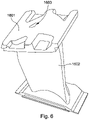
- FIG. 6 With reference to Figure 6 there is shown a perspective view of a blade 1601 that may also be inspected using the invention.
- the movable light source is inserted in internal passage 1603.
- the robot 201 has the ability to move in 6-axes, i.e. it can move with 6 degrees of freedom, for positioning and directing a camera 202 that is attached to the robot 201.
- the camera 202 may comprise a telesentric lens for the purpose of eradicating or minimising light distortion.
- the camera 202 may comprise a telesentric lens for the purpose of eradicating or minimising light distortion.
- the camera 202 may comprise a telesentric lens for the purpose of eradicating or minimising light distortion.
- FIG. 6 With reference to Figure 6 there is shown a perspective view of a blade 1601 that may also be inspected using the invention.
- the movable light source is inserted in internal passage 1603.
- the robot 201 has the ability to move in 6-axes, i.e. it can move with 6 degrees of freedom, for positioning and directing a camera 202 that is attached to the robot 201.
- the camera 202 may comprise a telesentric lens for the purpose of eradicating or minimising light distortion.
- the camera 202 may be a Teledyne ® DALSA Genie Nano camera and may have a slim body length of 21 mm.
- Camera 202 is positioned facing the external surface of the blade 101 and receives the light that shines through cooling holes 102 thereby creating an image such as that shown in Figures 15 and 16 .
- the robot 201 positions the camera 202 so that the optical axis of the camera 202 is aligned with the axis of a cooling hole that is to be imaged and inspected. Using this image, the inspection proceeds based on relevant measurements that are determined from post-processing of the image as will be discussed further below. The robot 201 then moves the camera 202 to align with the next cooling hole to be inspected.
- the fixture nest 205 is rotatable in order to aid inspection of cooling holes that are difficult for the camera to view within its range of motion.
- the combination of the rotation of the fixture nest 205, and 6 degrees of freedom movement ability of the camera 202 ensures that all cooling holes 102 may be inspected, even if the blade 101 has a complex surface topology.
- the fixture nest 205 is rotatable using a rotary servo 204 that is electrically actuated.
- Figures 3 and 4 show the apparatus as described above from different viewpoints. Features in Figures 3 and 4 are labelled with reference numerals as used in Figure 2 .
- the optical axis of the camera is aligned with the axis of a cooling hole that is to be imaged and inspected.
- the illumination source may be automatically moved to illuminate an internal passage.
- FIG. 7 - 9 there are shown example positions of the break-through point 1702 within holes 1701, 1801, 1901 that are to be inspected. It can be seen that holes may have different profiles.
- the camera is aligned with each individual hole for inspection in order to take an image that is to be post-processed.
- the camera must be correctly aligned in a vector position such as that referenced by VT, VE, and WE in Figures 7 - 9 in order to capture an image suitable for measuring break-through point 1702.
- Positions VT, VE, and WE are external to the vane and allow the camera to receive light that shines through holes 1701, 1801, 1901 from the illumination source contained within the internal passage.
- break-through point would not be visible using a conventional measuring technique involving use of a light source that shines light from the position of the camera since break-through point dimensions will be obscured by shadow and/or less visible due to angled internal walls of the hole.
- a base 2001 that can be used to support components such as blades or vanes that are to be inspected.
- the base 2001 holds components at a correct position for controllably moveable parts of the apparatus such as the camera and illumination means to be positioned correctly in order to operate.
- a datum position of the base is determined.
- the base holds components so that relevant features are at known mechanical locations relative to the datum position of the base.
- CAD models stored in memory of the controller may be used for this purpose.
- a known system such as the Erowa ® system comprising an Erowa base may be used.
- FIG 11 shows an alternative embodiment of the invention that includes a pair of robots comprising a gripping robot 401a and a camera robot 401b.
- Gripping robot 401a includes a gripping means (not shown).
- the gripping means is configured to have the ability to pick up (i.e. retrieve), move, and release vane 101.
- Camera robot 401b includes a camera 403.
- gripping robot 401a is programmed (or instructed by a computing device (not shown)) retrieve the blade 101 using the gripping means (not shown) and present the blade to one of the illumination probes that are mounted on illumination fixture 402.
- the blade 101 is presented to an illumination probe in a position so that an internal passage (not shown) of the blade 101 is illuminated. This is achieved by positioning the vane 101 so that the illumination probe enters an internal passage of the vane 101.
- the illumination probes are individually switchable on and off to ensure that light only shines from the internal passage of vane 101 during inspection.
- the camera robot 401b proceeds to direct camera 403 towards features on the vane 101 that are to be measured, such as holes. As discussed above, the camera receives the light that shines through the holes and creates an image such as that shown in Figures 9 and 10 . Relevant measurements are determined by post-processing this image as discussed below. Camera robot 401b is moved in order to align the optical axis of the camera 403 with the axis of a cooling hole that is to be measured. This is repeated in order to measure all cooling holes. Gripping robot 401a may move in order to position vane 101 in different positions to ensure that it is possible for all relevant features on vane 101 to be aligned with camera 403.
- the gripping robot 401a may transport the vane 101 to a suitable repository of inspected blades.
- the gripping robot 401a may place inspected blades in different repositories corresponding to the number of failures that have been detected as a result of the inspection.
- the illumination probes 402a, 402b, and 402c are pointing in different directions and are therefore suitable to provide illumination to different parts of the vane 101 when considering the movement range of the gripping robot 401a. For example, if there are multiple internal passages of the vane 101 that commence from different sides of the vane 101. The gripping robot 401a is instructed to present the vane 101 to the illumination probe that is most suitable to enable illumination of the features that are to be inspected.
- the robots may be synchronised so that the measuring process described above is fully automated. For example, a vane 101 may be retrieved and presented to an illumination probe by gripping robot 401a. Subsequently, camera robot 401b proceeds to position the camera 403 to take relevant images of features on vane 101. During this time, gripping robot 401a may adjust the position of blade 101 in order to ensure that all features are measured.
- the illumination sources are static. However, in other embodiments such as that discussed with reference to Figures 2 - 4 , the illumination source is controllably movable.
- a component support 606 for supporting components such as blades/vanes may be a fixture nest as shown in the embodiment of figures 2 - 4 , a gripping robot as shown in the embodiment of figure 5 , or an Erowa base as shown in Figure 10 .
- the component support 606, a controllable illumination source 607, and a camera robot 401b are connected to a computer terminal 603.
- a camera 403 is integrated into camera robot 401b.
- the computer terminal comprises internal memory and a processor.
- Robot Software 601 and Imaging Software 602 are installed on the Computer Terminal 603.
- Backup Storage 605 and Operator Interface 604 are connected to the computer terminal 603.
- the camera robot 401b has an image output connection to computer terminal 603.
- the camera robot 401b is configured to receive camera movement instructions from computer terminal 603 based on instructions generated by Robot Software 601.
- the camera movement instructions may be based on known positions of features of the component to be imaged in relation to a datum point on an Erowa base.
- An operator provides instructions to the computer terminal 603 and receives a user output via operator interface 604.
- Computer Terminal 603 has Robot Software 601 and Imaging Software 602 installed on internal memory. It will be appreciated that Robot Software 601 and Imaging Software 602 could be installed on separate computer terminals that are connected via a network. Alternatively, they could both be part of a single software package.
- Robot Software 601 runs using the processor of Computer Terminal 603 and provides outputs to one of the component support 606 and controllable illumination source 607. Outputs are also provided to camera robot 401b. These actions allow the camera to take appropriate images that have a contrast allowing for the features to be inspected by image post-processing.
- the resulting images taken by camera 403 are transferred to computer terminal 603, where they are post-processed by imaging software 602.
- the post-processing of images results in a part being determined to have passed or failed the inspection.
- a component movement instruction can be provided by Robot Software 601 to component support 606 resulting in a blade being placed in either a 'pass' repository or a 'fail' repository as appropriate. Data generated during this process is optionally stored in backup storage 605.
- one or both of the mounting and illumination source are positioned to provide a contrast of illumination between a feature of the component and an adjacent surface of the component.
- the camera robot positions the camera to align with a feature.
- Robot software on a computer terminal is used to provide instructions to appropriately move the camera robot.
- the camera on the camera robot captures an image of the feature. This image is transferred to the computer terminal.
- the image is post-processed using imaging software running on the computer terminal. The post-processing provides for relevant measurements of features to be determined based on the captured image. Features such as the size of a hole at the break-through point, the level of coating, and the size/shape/position of slots can be determined.
- step 705 measurements are compared with a predetermined tolerance. If the measurements are within acceptable boundary levels as set by the predetermined tolerance, then the feature is deemed to have passed the inspection. Otherwise, the feature is deemed to have failed the inspection. If there is more than one feature to be inspected, the camera robot re-positions the camera to align with another feature after step 705, as indicated by process arrow 707. It may be necessary for the inspected component to be moved, or for the illumination source to be repositioned. In this case, the process 701 is repeated as indicated by process arrow 708. For example, the illumination source may be positioned in a different internal passage so that more features are illuminated for inspection.
- this output is used to actuate the component support to place components in either a 'pass' or 'fail' repository depending on the result of the inspection.
- a component wall 809 separates the internal passage 802 of a component from an external area 804.
- Illumination probe 803 has been inserted inside the internal passage 802 and emits light 806.
- Camera 807 is mounted in the external area 804 on a camera robot (not shown).
- the optical axes of camera 807 has been positioned to be aligned with the axis of hole 801.
- Parallel dotted lines 805 represent a light beam emitted through the hole from illumination probe 803.
- Break-through point 808b is at the point where the hole 801 meets internal area 802. Usually this point is the smallest tightest part of the hole and where failures or manufacturing defects are most likely to occur.
- Figures 15 and 16 show example images from a computer terminal, as described above, that is running imaging software such as Dalsa Sherlock Vision.
- the computer terminal may be a personal computer and can be referred to as the controller.
- the computer terminal uses the imaging software to post-process images that have been taken by the camera and determine measurements of hole parameters based on the images.
- the post-processing allows the computer terminal to determine measurements of hole parameters based on images taken using a camera where an internal passage of a component has been illuminated, such as by using the illumination probes as discussed above.
- Figure 15 shows a raw image obtained by the camera 403. Illumination of the internal passage of the component provides for there to be a clear contrast between areas that comprise an aperture of the hole at the break-through point, and, the surrounding adjacent surface or walls of the hole.
- Figure 16 shows the image of Figure 15 after it has been post-processed by the computer terminal using the imaging software to determine a definitive edge 501 of cooling hole 502.
- the definitive edge 501 is determined based on the change of contrast between the area of each hole through which light is shining, and the dark surrounding adjacent surface of the blade 101, or wall of the hole 502. This is the "break-through" point where failure is most likely to occur and therefore it is most desirable to measure the size of the hole at this point.
- the break-through point is the point at which the hole reaches a surface within the internal cavity.
- the imaging software is programmed to measure a dimension of the hole 502 such as diameter at the break-through point using the definitive edge 501.
- the imaging software may be programmed to measure dimensions such as the width and height of the hole as defined by the definitive edge 501.
- the shape of the hole 502 can be determined and compared with a predetermined shape that the hole 502 is expected to be such as a perfect circle.
- the software may display an output image to an operator where holes 1104 are colour coded based on whether the dimensions that have been determined are within pre-set tolerances. For example, holes where a diameter at the break-through point is too large or too small (i.e. outside the pre-set tolerance) may be coloured red. This allows the operator to obtain an overview of how many holes are within the pre-set tolerance.
- the software may be configured to send instructions to the robot(s) to retain blades (i.e. place in a "fail" repository) that have failed the inspection. Blades may fail the inspection based on one or both of the number of hole measurements outside the pre-set tolerance, and, the degree to which any measurements are outside the pre-set tolerance.
- the software is optionally configured to store data relating to each inspected blade on a hard drive or server.
- the component can be positioned so that an adjacent surface is illuminated.
- illumination is provided by a source such as an illumination probe that is not inside an internal passage of the blade. Instead, the illumination source shines light onto the adjacent surface from a position facing this surface. This provides for the controller to inspect a level of coating on the adjacent surface.
- FIG. 18 With reference to Figure 18 there is shown a typical image taken by the camera when the controller is configured to inspect a coating level.
- the holes are shown as being dark because the light source is facing the adjacent surface, and, the internal passage that the holes lead to is not illuminated.
- three areas 1201, 1202, and 1203 are identifiable based on the contrast and differing tones of the image. It is possible to determine the coating level based on the tone shown on a surface within the image. In this example, surface areas 1202 and 1203 have a thin coating since the tone is darker. Surface area 1201 has a thicker coating since the tone is lighter.
- each pixel has a value of between 0 and 255 depending on the tone, 0 being black and 255 being white.
- a coating percentage is applied between 0 and 100% based on the pixel value within the image. Pixel values can be calibrated based on samples that have been predetermined to correlate to different percentages.
- the black (“fail”) areas 1202, 1203 represent areas where the coating level is too thin based on a pre-set tone limit.
- the pre-set tone limit may be set where it has been predetermined what tone represents a coating level that is too thin.
- the white (“pass") area 1201 represents an area where the coating level is sufficient.
- the software may be configured to colour-code areas depending on the coating level.
- the controller may be configured to move one or more of the mounting and illumination source such that a surface 1402 adjacent to the slot features 1401 is illuminated.
- the controller determines measurements relating to the size of the slots 1401 utilising the definitive edges of the slots as is clear from the contrast of an image obtained using the camera.
- the robots used as part of the controller may be a 6-axis Kuka or Mitsubishi Robot.
- the computer software may run on a computer terminal being a personal computer that is part of the controller.
- the controller and/or computer terminal may be programmed using the C or C+ language.
- the controller may also be a ladder based PLC system.
- each robotic arm positions one of a camera, mounting, or illumination device. In examples, only two of the camera, mounting, or illumination device are mounted on robotic arms.
- a datum sphere 2402 is positioned at a known position relative to a mounting (not shown).
- the mounting (not shown) holds a turbine blade or vane (2403).
- the position of the mounting (and therefore coordinate positions of features of the turbine blade or vane) are determined based on the position of the datum sphere 2402 as determined by a camera 2401.
- Components of the apparatus can be moved as discussed above so that the optical axis of the camera 2401 is aligned with a centreline of one or more cooling holes 2404 on the turbine blade or vane 2403.
Landscapes
- General Physics & Mathematics (AREA)
- Physics & Mathematics (AREA)
- Pathology (AREA)
- Biochemistry (AREA)
- Immunology (AREA)
- Health & Medical Sciences (AREA)
- Life Sciences & Earth Sciences (AREA)
- Chemical & Material Sciences (AREA)
- Analytical Chemistry (AREA)
- General Health & Medical Sciences (AREA)
- Engineering & Computer Science (AREA)
- Mechanical Engineering (AREA)
- General Engineering & Computer Science (AREA)
- Multimedia (AREA)
- Theoretical Computer Science (AREA)
- Length Measuring Devices By Optical Means (AREA)
- Investigating Materials By The Use Of Optical Means Adapted For Particular Applications (AREA)
Description
- Systems and methods for inspecting turbine vanes and blades.
- Turbine vanes and blades such as those used in the aerospace and industrial gas generator industries may include cooling holes. The cooling holes serve to provide external blade cooling by injecting a cooling fluid such as cold air through the holes. This creates a thin film cooling layer on an external surface of a blade that cools the blade and provides some protection from external heat.
- Each turbine blade or vane may be manufactured with tens or hundreds of cooling holes that are in the region of a few mm in diameter. As part of the manufacturing process, it is necessary to inspect the cooling holes of a completed blade to ensure that they conform to required quality tolerances. This is particularly important because flaws in cooling holes can lead to blade or vane failures during turbine operation. Traditionally cooling hole inspection has been undertaken by inspectors who manually use pin gauges to individually check that the dimensions of each cooling hole are within the required tolerances. This is a very time-consuming and laborious process.
- Attempts have been made to improve this process. Rotary video measurement machines use imaging to automatically determine the dimensions of cooling holes. However there are several disadvantages with this method. Failures occurring at points not at a surface facing a camera are not detected. Furthermore, existing systems are slow to operate. It can take up to 5 minutes to align datums of the imaging device and a hole before measurements can be taken.
- It is also desirable for other features of blades to be automatically inspected such as the dimensions (position and width) of slots and the thickness of coatings.
- The present invention has been devised with the foregoing in mind.
WO2009/141606A1 discloses an optical inspection probe for obtaining and providing images of an object to be inspected. -
US6723951B1 discloses a method for determining the angular orientation of a hole in a component relative to the component's surface. -
EP2423638A2 discloses an apparatus for determining variable thickness of a coating on a surface of a substrate. -
WO2015/124756A1 discloses a method of inspecting a hole in an object with at least one camera probe mounted on a coordinate positioning machine. - The invention relates to a turbine blade or vane inspection apparatus according to claim 1 and a method for inspecting a turbine blade or vane according to claim 9.
- The controller may be configured to control movement of one or both of the mounting and source of illumination. As used herein, the term "control the movable components" refers to controlling the motion of (or controllably moving) the moveable components so that they are positioned in a desired location and/or orientation.
- The illumination source may comprise a fibre optic light source.
- The illumination source comprises an illumination probe and the controller is configured to control the movable components to position the turbine blade or vane so that the illumination probe enters an internal passage of the turbine blade or vane and radiation from the illumination probe shines out from the internal passage through one or more cooling holes in the turbine blade or vane.
- It is possible for only the illumination probe to be controllably movable and positioned by the controller if the mounting is not moveable.
- Radiating light from an internal passage (i.e. through the hole to the adjacent surface) provides for the dimensions of the profile of a hole at the so-called "break-through" point to be measured. The "break-through" point may be the profile of the cooling hole near or at the location where the cooling hole joins the internal passage. Therefore the dimensions may not be easily visible when light is radiated from an illumination source facing the adjacent surface, as is the case in existing systems, due to shadow. It will be appreciated that the break-through point is where a manufacturing defect or failure is most likely to occur. The break-through point may be at the narrowest point of the hole, or at the deepest point of the hole profile from the surface.
- The controller is configured to control the moveable components so that the optical axis of the camera is aligned with a centreline of a cooling hole. The controller may be configured to position the camera so that the optical axis of the camera (such as the optical axis of a lens of the camera) is aligned with a centreline of a cooling hole.
- The controller is configured to determine dimensions of a profile of the cooling hole at the break-through point.
- The break-through point may be proximal to (or at) the location where the cooling hole joins the internal passage and it is desirable to measure the dimensions of the hole at this point since, as discussed above, it is usually where failure is most likely to occur.
- The controller may be configured to determine a definitive edge of a profile of the cooling hole(s) based on the change of contrast in the image caused by light illuminated from the illumination probe. The definitive edge can be considered to be a virtual edge that can be measured using image processing software installed on a computing device.
- The apparatus is configured for the camera to receive radiation from the illumination probe after the radiation has passed through the cooling hole(s).
- The mounting may comprise a datum point and the controller may determine the position of the mounting based on the position of the datum point. The controller may comprise memory that stores coordinate positions of features of the blade or vane with respect to the datum point and the controller may be configured to move any of the camera, mounting, and illumination source based on the position of the mounting and stored coordinate positions.
- According to a second example which is not claimed and is useful for understanding the invention there is provided a method for inspecting a turbine blade or vane. The method may comprise the steps of:
- controlling moveable components being at least two of a mounting for holding a turbine blade or vane, a camera, and an illumination source, to position the turbine blade or vane relative to the illumination source so as to provide a contrast of illumination between a feature of the turbine blade or vane and an adjacent surface of the blade or vane.
- controlling the moveable components so that the optical axis of the camera is directed towards the feature.
- determining a dimension and/or shape of the feature based on an image obtained by the camera.
- The illumination source may comprise a fibre optic light source.
- The illumination source may comprise an illumination probe, and further comprise the step of controlling the moveable components to position the turbine blade or vane so that the illumination probe enters an internal passage of the turbine blade or vane and radiation from the illumination probe shines out from the internal passage through one or more cooling holes in the turbine blade or vane.
- The method may further comprise the step of positioning the movable components so that the optical axis of the camera is aligned with a centreline of one of the one or more cooling holes. The step of positioning the movable components so that the optical axis of the camera is aligned with a centreline of one of the one or more cooling holes may comprise moving the camera.
- The method may further comprise the step of determining a definitive edge of a profile of the cooling hole(s) based on the change of contrast in the image caused by light illuminated from the illumination probe.
- The method may further comprise the step of post-processing the image using imaging software installed on a computing device to determine the definitive edge and use data associated with the definitive edge to determine the dimension and/or shape of the cooling hole(s).
- The method may further comprise the step of comparing the dimension and/or shape with a predetermined tolerance range in order to determine if the dimension and/or shape is acceptable or unacceptable.
- The method may further comprise the step of receiving the radiation from the illumination probe after the radiation has passed through the cooling hole(s).
- According to a third example which is not claimed and is useful for understanding the invention there is provided a system for inspecting a turbine blade or vane, the system comprising:
- a computer terminal having installed software that post-processes images to determine a dimension and/or shape of a feature based on a contrast of illumination between a feature of the turbine blade or vane and an adjacent surface of the blade or vane.
- one or more robots for controllably moving at least one of a camera, a mounting for holding a turbine vane or blade, and an illumination source.
- The one or more robots may comprise a camera robot for controllably moving a camera, and a component support robot for controllably moving the mounting.
- The robots may be controlled by the computer terminal, or a further secondary computer terminal utilising robot software.
- The one or more robots may be configured to move the at least one of the camera, the mounting for holding the turbine vane or blade, and an illumination source, by reference to stored coordinates positions of features on the turbine blade or vane with respect to a measurable datum point on the mounting.
- According to a fourth example, which is not claimed and is useful for understanding the invention there is provided a turbine blade or vane coating inspection apparatus comprising: a mounting for holding a turbine blade or vane; a source of illumination for illuminating a coated surface of the turbine blade or vane; a camera; and a controller. At least one of the mounting, the source of illumination and the camera is controllably moveable. The controller is configured to: control movement of one or more of the mounting, the source of illumination and the camera so that the optical axis of the camera is directed towards the coated surface of the turbine blade or vane in a predetermined direction; and determine an acceptable or unacceptable thickness of coating based on:
- radiation reflected from the illuminated surface as determined from an image obtained by the camera and
- a predetermined relationship between the amount of coating applied and the corresponding amount of radiation reflected from the illuminated surface.
- The apparatus may be configured to determine a coating thickness percentage value for each pixel in the image by determining a pixel brightness value and comparing the pixel brightness value with stored coating percentage values using the predetermined relationship.
- The apparatus may be configured to be trained to differentiate between coatings based on stored coating image profiles determined from images of samples having acceptable and unacceptable coating levels.
- The time taken to measure a blade or vane (i.e. the TAKT time) using the described apparatus and method is estimated to be 6 - 7 minutes depending on the topological complexity of the blade or vane. This is much quicker than what would be achieved using a manual or other known imaging procedure.
-
-
Figure 1 shows a turbine vane that can be inspected using an embodiment of the invention. -
Figure 2 shows a plan view of an example inspection apparatus useful for understanding the invention. -
Figure 3 shows an isometric view of the inspection apparatus ofFigure 2 . -
Figure 4 shows a side view of the inspection apparatus ofFigure 2 . -
Figure 5 shows a perspective view of a vane, which can be inspected using an embodiment of the invention, displaying access to internal passages. -
Figure 6 shows perspective view of a blade, which can be inspected using an embodiment of the invention, displaying access to an internal passage. -
Figures 7 to 9 show cross-sectional views of cooling holes that can be inspected using embodiments of the invention. -
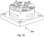
Figure 10 shows a base upon which a blade or vane can be mounted. -
Figure 11 shows a side view of an inspection apparatus embodiment of the invention where there are two robots. -
Figure 12 shows a schematic diagram of devices within an inspection apparatus ofFigures 2 to 4 . -
Figure 13 shows a flow diagram of an inspection process undertaken by an inspection apparatus ofFigures 2 to 4 . -
Figure 14 shows a close-up cross-sectional representation of a wall of a component having a hole to be inspected by an inspection apparatus ofFigures 2 to 4 . -
Figure 15 shows a screenshot from a computer terminal showing an image of holes obtained using an embodiment of the invention. -
Figure 16 shows a screenshot from a computer terminal showing a post-processed image of holes obtained using an embodiment of the invention. -
Figure 17 shows a screenshot from a computer terminal showing a post-processed image of holes obtained using an embodiment of the invention, including colour coded analysis of failure. -
Figure 18 shows a screenshot from a computer terminal showing an image of surface coatings obtained using an embodiment of the invention. -
Figure 19 shows a screenshot from a computer terminal showing a post-processed image of surface coatings obtained using an embodiment of the invention. -
Figure 20 shows slots of a vane that are inspected using an embodiment of the invention. -
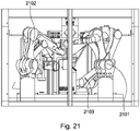
Figure 21 shows a side view of an apparatus according to an embodiment of the invention. -
Figure 22 shows an isometric view of an apparatus according to an embodiment of the invention. -
Figure 23 shows an example datum point for determining a position of a mounting according to an embodiment of the invention. - With reference to
Figure 1 there is shown a turbine vane "vane" 101 havingcooling holes 102 that the present invention can be used to inspect. The cooling holes 102 connect an internal cavity (not shown) with anexternal surface 104. The cooling holes transport a cooling fluid from the internal cavity to theexternal surface 104. - With reference to
Figures 2 to 4 there is shown an apparatus for inspecting a blade or vane, such as thevane 101 ofFigure 1 . There is arobot 201 that supports acamera 202. Thevane 101 is affixed to a base 205 that may be referred to as afixture nest 205. A moveablelight source 203 is controlled to shine light from within an internal passage (not shown inFigures 2 - 4 ) of thevane 101. The internal passage is accessible from a side surface (not shown inFigures 2 - 4 ) of thevane 101. Therobot 201,fixture nest 205,light source 203 and other associated components discussed above are optionally placed within guardingbox 207 to ensure safe operation. - With reference to
Figure 5 there is shown a perspective view ofvane 101. It can be seen that there areinternal passages 1501 on theside surface 1502. In the embodiment shown inFigures 2 - 4 , the moveable light source (as represented by feature 1503) is inserted into one ofinternal passages 1501 thereby providing for light to shine through the cooling holes 102. - With reference to
Figure 6 there is shown a perspective view of ablade 1601 that may also be inspected using the invention. The movable light source is inserted ininternal passage 1603. - With continued reference to
figures 2 - 4 , therobot 201 has the ability to move in 6-axes, i.e. it can move with 6 degrees of freedom, for positioning and directing acamera 202 that is attached to therobot 201. Thecamera 202 may comprise a telesentric lens for the purpose of eradicating or minimising light distortion. For example, the camera - With reference to
Figure 6 there is shown a perspective view of ablade 1601 that may also be inspected using the invention. The movable light source is inserted ininternal passage 1603. - With continued reference to
figures 2 - 4 , therobot 201 has the ability to move in 6-axes, i.e. it can move with 6 degrees of freedom, for positioning and directing acamera 202 that is attached to therobot 201. Thecamera 202 may comprise a telesentric lens for the purpose of eradicating or minimising light distortion. For example, thecamera 202 may be a Teledyne ® DALSA Genie Nano camera and may have a slim body length of 21 mm. -
Camera 202 is positioned facing the external surface of theblade 101 and receives the light that shines throughcooling holes 102 thereby creating an image such as that shown inFigures 15 and 16 . With continued reference toFigures 2 - 4 , therobot 201 positions thecamera 202 so that the optical axis of thecamera 202 is aligned with the axis of a cooling hole that is to be imaged and inspected. Using this image, the inspection proceeds based on relevant measurements that are determined from post-processing of the image as will be discussed further below. Therobot 201 then moves thecamera 202 to align with the next cooling hole to be inspected. - The
fixture nest 205 is rotatable in order to aid inspection of cooling holes that are difficult for the camera to view within its range of motion. The combination of the rotation of thefixture nest 205, and 6 degrees of freedom movement ability of thecamera 202 ensures that all coolingholes 102 may be inspected, even if theblade 101 has a complex surface topology. - If rotation is required, the
fixture nest 205 is rotatable using arotary servo 204 that is electrically actuated. -
Figures 3 and4 show the apparatus as described above from different viewpoints. Features inFigures 3 and4 are labelled with reference numerals as used inFigure 2 . - As discussed above, the optical axis of the camera is aligned with the axis of a cooling hole that is to be imaged and inspected. Furthermore, the illumination source may be automatically moved to illuminate an internal passage. Features that provide this functionality are now described in more detail.
- With reference to
Figures 7 - 9 there are shown example positions of the break-throughpoint 1702 withinholes Figures 7 - 9 in order to capture an image suitable for measuring break-throughpoint 1702. Positions VT, VE, and WE are external to the vane and allow the camera to receive light that shines throughholes - With reference to
Figure 10 there is shown abase 2001 that can be used to support components such as blades or vanes that are to be inspected. Thebase 2001 holds components at a correct position for controllably moveable parts of the apparatus such as the camera and illumination means to be positioned correctly in order to operate. - In order for the camera and illumination source to be positioned correctly, a datum position of the base is determined. The base holds components so that relevant features are at known mechanical locations relative to the datum position of the base. CAD models stored in memory of the controller may be used for this purpose. By determining a datum position of the base, it is possible for the controller to ascertain the location of features on the blade in three dimensions for automatic positioning of the camera and illumination source. Aknown system such as the Erowa ® system comprising an Erowa base may be used.
-
Figure 11 shows an alternative embodiment of the invention that includes a pair of robots comprising agripping robot 401a and acamera robot 401b.Gripping robot 401a includes a gripping means (not shown). The gripping means is configured to have the ability to pick up (i.e. retrieve), move, andrelease vane 101.Camera robot 401b includes acamera 403. There is also alighting fixture 402 that includes a plurality ofillumination probes vane 101,gripping robot 401a is programmed (or instructed by a computing device (not shown)) retrieve theblade 101 using the gripping means (not shown) and present the blade to one of the illumination probes that are mounted onillumination fixture 402. Theblade 101 is presented to an illumination probe in a position so that an internal passage (not shown) of theblade 101 is illuminated. This is achieved by positioning thevane 101 so that the illumination probe enters an internal passage of thevane 101. The illumination probes are individually switchable on and off to ensure that light only shines from the internal passage ofvane 101 during inspection. - Once the blade has been positioned so that an internal passage is illuminated, the
camera robot 401b proceeds todirect camera 403 towards features on thevane 101 that are to be measured, such as holes. As discussed above, the camera receives the light that shines through the holes and creates an image such as that shown inFigures 9 and10 . Relevant measurements are determined by post-processing this image as discussed below.Camera robot 401b is moved in order to align the optical axis of thecamera 403 with the axis of a cooling hole that is to be measured. This is repeated in order to measure all cooling holes.Gripping robot 401a may move in order to positionvane 101 in different positions to ensure that it is possible for all relevant features onvane 101 to be aligned withcamera 403. After all relevant surface features are imaged/inspected, the grippingrobot 401a may transport thevane 101 to a suitable repository of inspected blades. Thegripping robot 401a may place inspected blades in different repositories corresponding to the number of failures that have been detected as a result of the inspection. - As shown in
Figure 11 , theillumination probes vane 101 when considering the movement range of thegripping robot 401a. For example, if there are multiple internal passages of thevane 101 that commence from different sides of thevane 101. Thegripping robot 401a is instructed to present thevane 101 to the illumination probe that is most suitable to enable illumination of the features that are to be inspected. - The robots may be synchronised so that the measuring process described above is fully automated. For example, a
vane 101 may be retrieved and presented to an illumination probe by grippingrobot 401a. Subsequently,camera robot 401b proceeds to position thecamera 403 to take relevant images of features onvane 101. During this time, grippingrobot 401a may adjust the position ofblade 101 in order to ensure that all features are measured. - Whilst the embodiment shown in
Figure 11 includes a pair of robots, there may be further robots acting as either camera robots or gripping robots. - In the embodiment shown in
Figure 11 , the illumination sources (illumination probes Figures 2 - 4 , the illumination source is controllably movable. - With reference to
Fig. 12 there is shown a schematic diagram of an apparatus according to an embodiment of the present invention. Acomponent support 606 for supporting components such as blades/vanes may be a fixture nest as shown in the embodiment offigures 2 - 4 , a gripping robot as shown in the embodiment offigure 5 , or an Erowa base as shown inFigure 10 . Thecomponent support 606, acontrollable illumination source 607, and acamera robot 401b are connected to acomputer terminal 603. Acamera 403 is integrated intocamera robot 401b. The computer terminal comprises internal memory and a processor.Robot Software 601 andImaging Software 602 are installed on theComputer Terminal 603.Backup Storage 605 andOperator Interface 604 are connected to thecomputer terminal 603. Thecamera robot 401b has an image output connection tocomputer terminal 603. Thecamera robot 401b is configured to receive camera movement instructions fromcomputer terminal 603 based on instructions generated byRobot Software 601. The camera movement instructions may be based on known positions of features of the component to be imaged in relation to a datum point on an Erowa base. An operator provides instructions to thecomputer terminal 603 and receives a user output viaoperator interface 604.Computer Terminal 603 hasRobot Software 601 andImaging Software 602 installed on internal memory. It will be appreciated thatRobot Software 601 andImaging Software 602 could be installed on separate computer terminals that are connected via a network. Alternatively, they could both be part of a single software package. -
Robot Software 601 runs using the processor ofComputer Terminal 603 and provides outputs to one of thecomponent support 606 andcontrollable illumination source 607. Outputs are also provided tocamera robot 401b. These actions allow the camera to take appropriate images that have a contrast allowing for the features to be inspected by image post-processing. The resulting images taken bycamera 403 are transferred tocomputer terminal 603, where they are post-processed byimaging software 602. The post-processing of images results in a part being determined to have passed or failed the inspection. Based on this information, a component movement instruction can be provided byRobot Software 601 tocomponent support 606 resulting in a blade being placed in either a 'pass' repository or a 'fail' repository as appropriate. Data generated during this process is optionally stored inbackup storage 605. - With reference to
Figure 13 , there is shown an example inspection process, which is not claimed and is useful for understanding the invention. - At
step 701, one or both of the mounting and illumination source are positioned to provide a contrast of illumination between a feature of the component and an adjacent surface of the component. During step 702, the camera robot positions the camera to align with a feature. Robot software on a computer terminal is used to provide instructions to appropriately move the camera robot. - During
step 703, the camera on the camera robot captures an image of the feature. This image is transferred to the computer terminal. During step 704, the image is post-processed using imaging software running on the computer terminal. The post-processing provides for relevant measurements of features to be determined based on the captured image. Features such as the size of a hole at the break-through point, the level of coating, and the size/shape/position of slots can be determined. - During
step 705, measurements are compared with a predetermined tolerance. If the measurements are within acceptable boundary levels as set by the predetermined tolerance, then the feature is deemed to have passed the inspection. Otherwise, the feature is deemed to have failed the inspection. If there is more than one feature to be inspected, the camera robot re-positions the camera to align with another feature afterstep 705, as indicated byprocess arrow 707. It may be necessary for the inspected component to be moved, or for the illumination source to be repositioned. In this case, theprocess 701 is repeated as indicated byprocess arrow 708. For example, the illumination source may be positioned in a different internal passage so that more features are illuminated for inspection. After all relevant features have been inspected, or during the inspection, the operator is notified of the results via an output from the computer terminal. In some embodiments this output is used to actuate the component support to place components in either a 'pass' or 'fail' repository depending on the result of the inspection. - With reference to
Figure 14 , there is shown a cross-sectional diagram of a hole that can be inspected using devices described herein. - A
component wall 809 separates theinternal passage 802 of a component from anexternal area 804. There is acooling hole 801 in thewall 809.Illumination probe 803 has been inserted inside theinternal passage 802 and emits light 806.Camera 807 is mounted in theexternal area 804 on a camera robot (not shown). The optical axes ofcamera 807 has been positioned to be aligned with the axis ofhole 801. Paralleldotted lines 805 represent a light beam emitted through the hole fromillumination probe 803. Break-throughpoint 808b is at the point where thehole 801 meetsinternal area 802. Usually this point is the smallest tightest part of the hole and where failures or manufacturing defects are most likely to occur. - In order to measure the dimensions of the hole at the break-through
point 808b, light emitted through the hole fromillumination probe 803 is captured bycamera 807. As shown infigure 8 , the edges oflight beam 805 are substantially parallel. Therefore, it is possible to determine the size ofbreakthrough point 808b by post-processing the resulting image. -
Figures 15 and 16 show example images from a computer terminal, as described above, that is running imaging software such as Dalsa Sherlock Vision. The computer terminal may be a personal computer and can be referred to as the controller. The computer terminal uses the imaging software to post-process images that have been taken by the camera and determine measurements of hole parameters based on the images. The post-processing allows the computer terminal to determine measurements of hole parameters based on images taken using a camera where an internal passage of a component has been illuminated, such as by using the illumination probes as discussed above. -
Figure 15 shows a raw image obtained by thecamera 403. Illumination of the internal passage of the component provides for there to be a clear contrast between areas that comprise an aperture of the hole at the break-through point, and, the surrounding adjacent surface or walls of the hole. - It can be seen from
Figures 15 and 16 that the robot(s) has aligned the optical axis of thecamera 403 with the axis of a cooling hole that is to be measured 502. -
Figure 16 shows the image ofFigure 15 after it has been post-processed by the computer terminal using the imaging software to determine adefinitive edge 501 ofcooling hole 502. Thedefinitive edge 501 is determined based on the change of contrast between the area of each hole through which light is shining, and the dark surrounding adjacent surface of theblade 101, or wall of thehole 502. This is the "break-through" point where failure is most likely to occur and therefore it is most desirable to measure the size of the hole at this point. As discussed above, the break-through point is the point at which the hole reaches a surface within the internal cavity. By providing illumination inside the internal cavity of the turbine blade or vane, the change of contrast between light and dark occurs at the circumference of the hole at the break-through point, as seen by the camera when it is aligned with the axis of the cooling hole. - The imaging software is programmed to measure a dimension of the
hole 502 such as diameter at the break-through point using thedefinitive edge 501. The imaging software may be programmed to measure dimensions such as the width and height of the hole as defined by thedefinitive edge 501. The shape of thehole 502 can be determined and compared with a predetermined shape that thehole 502 is expected to be such as a perfect circle. - With reference to
Figure 17 , the software may display an output image to an operator whereholes 1104 are colour coded based on whether the dimensions that have been determined are within pre-set tolerances. For example, holes where a diameter at the break-through point is too large or too small (i.e. outside the pre-set tolerance) may be coloured red. This allows the operator to obtain an overview of how many holes are within the pre-set tolerance. The software may be configured to send instructions to the robot(s) to retain blades (i.e. place in a "fail" repository) that have failed the inspection. Blades may fail the inspection based on one or both of the number of hole measurements outside the pre-set tolerance, and, the degree to which any measurements are outside the pre-set tolerance. - The software is optionally configured to store data relating to each inspected blade on a hard drive or server.
- The component can be positioned so that an adjacent surface is illuminated. In other words, illumination is provided by a source such as an illumination probe that is not inside an internal passage of the blade. Instead, the illumination source shines light onto the adjacent surface from a position facing this surface. This provides for the controller to inspect a level of coating on the adjacent surface.
- Apparatus and methods which are not claimed without the features of claim 1 or claim 9, are described with reference to
Figures 18 to 23 . With reference toFigure 18 there is shown a typical image taken by the camera when the controller is configured to inspect a coating level. The holes are shown as being dark because the light source is facing the adjacent surface, and, the internal passage that the holes lead to is not illuminated. In the example shown inFigure 18 , threeareas surface areas Surface area 1201 has a thicker coating since the tone is lighter. - With reference to
Figure 19 there is shown an example output of the controller after post-processing the image shown inFigure 18 based on tone. Illumination may be applied in a consistent and controlled manner allowing the camera to detect how much light is being reflected from the surface of the blade. There is a direct relationship between the amount of coating applied and the amount of light that is reflected back into the camera. The amount of light received by the camera from any point on the surface can be calibrated to the coating thickness when the optical axis of the camera is directed towards the coated surface in a given direction (e.g. angle of the optical axis of the camera to the surface). In the output shown inFigure 18 , each pixel has a value of between 0 and 255 depending on the tone, 0 being black and 255 being white. A coating percentage is applied between 0 and 100% based on the pixel value within the image. Pixel values can be calibrated based on samples that have been predetermined to correlate to different percentages. - The black ("fail")
areas area 1201 represents an area where the coating level is sufficient. The software may be configured to colour-code areas depending on the coating level. - With reference to
Figure 20 there is shown avane 101 having slot features 1401. The controller may be configured to move one or more of the mounting and illumination source such that asurface 1402 adjacent to the slot features 1401 is illuminated. The controller determines measurements relating to the size of theslots 1401 utilising the definitive edges of the slots as is clear from the contrast of an image obtained using the camera. - The robots used as part of the controller may be a 6-axis Kuka or Mitsubishi Robot. The computer software may run on a computer terminal being a personal computer that is part of the controller. The controller and/or computer terminal may be programmed using the C or C+ language. The controller may also be a ladder based PLC system.
- With reference to
Figures 21 and22 , threerobotic arms - With reference to
Figure 23 , adatum sphere 2402 is positioned at a known position relative to a mounting (not shown). The mounting (not shown) holds a turbine blade or vane (2403). The position of the mounting (and therefore coordinate positions of features of the turbine blade or vane) are determined based on the position of thedatum sphere 2402 as determined by acamera 2401. Components of the apparatus can be moved as discussed above so that the optical axis of thecamera 2401 is aligned with a centreline of one ormore cooling holes 2404 on the turbine blade orvane 2403.
Claims (15)
- A turbine blade or vane inspection apparatus for use during a manufacturing process, comprising:a mounting (205) for holding a turbine blade or vane (101);a source of illumination (203);a camera (202);a controller;wherein at least two of the source of illumination (203), the camera (202), andthe mounting (205) are moveable components;and,wherein the controller is configured to:control the movable components to (a) position (701) the turbine blade or vane mounted thereon relative to the illumination source so as to provide a contrast of illumination between a cooling hole in the turbine blade or vane and an adjacent surface of the turbine blade or vane and (b) position (702) the camera (202) so that the optical axis of the camera (202) is directed towards the cooling hole so that the optical axis of the camera (202) is aligned with a centreline of the hole (102); andmeasure a size of a profile of the cooling hole at the break-through point as the narrowest point of the cooling hole, the measurement being based on an image obtained by the camera (202), wherein the illumination source (203) comprises an illumination probe and the controller is configured to control the movable components to position the turbine blade or vane (101) so that the illumination probe enters the internal passage of the turbine blade or vane (101) and radiation from the illumination probe shines out from the internal passage through the cooling hole (102) in the turbine blade or vane (101)..
- The apparatus according to claim 1 wherein the illumination source (203) comprises a fibre optic light source.
- The apparatus of claim 1 or claim 2, wherein the controller is configured to determine a circumference size and/or shape of the cooling hole (102) at or proximal to the location where the cooling hole joins the internal passage.
- The apparatus of any of claims 1 to 3 wherein the controller is configured to determine a definitive edge of a profile of one or more cooling hole(s) (102) based on the change of contrast in the image caused by radiation from the illumination probe.
- The apparatus of any of claims 1 to 4 wherein the apparatus is configured for the camera (202) to receive the radiation from the illumination probe after the radiation has passed through the cooling hole(s) (102).
- The apparatus according to claim 1 wherein the controller is further configured to control the moveable components to (a) position the turbine blade or vane so that the illumination source illuminates a coated surface of the blade or vane (101), and (b) to position the camera (202) so that the optical axis of the camera (202) is directed towards the illuminated surface, and wherein the controller is further configured to determine an acceptable or unacceptable thickness of coating based on radiation reflected from the illuminated surface, and optionally, wherein the controller is configured to determine an acceptable or unacceptable thickness of coating based on a predetermined relationship between the amount of coating applied and corresponding amount of radiation reflected from the illuminated surface.
- The apparatus according to claim 1 wherein the feature of the turbine blade or vane (101) is a slot or opening (1401) in the adjacent surface (1402) of the blade or vane (101), and the controller is configured to control the moveable components to (a) position the turbine blade or vane (101) so that the illumination source (203) illuminates the surface, and (b) to position the camera so that the optical axis of the camera (202) is directed towards the slot or opening (1401), and wherein the controller is further configured to determine the shape of the opening (1401) based on the image obtained by the camera (202).
- The apparatus according to any preceding claim, wherein:the mounting (205) comprises a datum point and the controller determines the position of the mounting (205) based on the position of the datum point;the controller comprises memory that stores coordinate positions of features of the blade or vane (101) with respect to the datum point; andthe controller is configured to move any of the camera (202), mounting (205), and illumination source (203) based on the position of the mounting and stored coordinate positions.
- A method for inspecting a turbine blade or vane (101) during a manufacturing
process, the method comprising the steps of:controlling (701) moveable components being at least two of a mounting (205) for holding a turbine blade or vane (101), a camera (202), and an illumination source (203), to position the turbine blade or vane (101) relative to the illumination source (203) so as to provide a contrast of illumination between a cooling hole of the turbine blade or vane (101) and an adjacent surface of the blade or vane (101);controlling (702) the moveable components so that the optical axis of the camera (202) is directed towards the cooling hole so that the optical axis of the camera (202) is aligned with a centreline of the cooling hole; andmeasuring (704) a size of a profile of the cooling hole at the break-through point as the narrowest point of the hole, the measurement being based on an image obtained by the camera; andwherein the illumination source (203) comprises an illumination probe; and further comprising the step of controlling the movable components to position the turbine blade or vane so that the illumination probe enters an internal passage of the turbine blade or vane (101) and radiation from the illumination probe shines out from the internal passage through one or more cooling holes (102) in the turbine blade or vane (101). - The method according to claim 9 wherein the illumination source (203) comprises a fibre optic light source.
- The method according to any of claims 9 or 10 further comprising the step of determining a definitive edge of a profile of the cooling hole(s) (102) based on the change of contrast in the image caused by light illuminated from the illumination probe, and optionally, further comprising the step of post-processing the image using imaging software installed on a computing device to determine the definitive edge and use data associated with the definitive edge to determine the dimension and/or shape of the cooling hole(s) (102), and further optionally, further comprising the step of comparing the dimension and/or shape with a predetermined tolerance range in order to determine if the dimension and/or shape is acceptable or unacceptable.
- The method according to any of claims 9 to 11 further comprising the step of receiving the radiation from the illumination probe after the radiation has passed through the cooling hole(s) (102).
- The apparatus of any of claims 1 to 8,
wherein the controller comprises a computer terminal (603) having installed software that post-processes images to determine the dimension and/or shape of the feature based on a contrast of illumination between the feature of the turbine blade or vane (101) and an adjacent surface of the blade or vane (101); and
the controller further comprises one or more robots (401a, 401b) for controllably moving at least one of the camera (202), the mounting (205) for holding the turbine vane or blade (101), and the illumination source (203). - The apparatus according to claim 13 wherein the one or more robots (401a, 401b) comprises a camera robot (401b) for controllably moving the camera (202), and a component support robot for controllably moving the mounting (205), and optionally, wherein the robots (401a, 401b) are controlled by the computer terminal (603), or a further secondary computer terminal utilising robot software.
- The apparatus according to any of claims 13 or 14 wherein the one or more robots (401a, 401b) are configured to move the at least one of the camera (202), the mounting for holding the turbine vane or blade (205), and an illumination source (203), by reference to stored coordinates positions of features on the turbine blade or vane (101) with respect to a measurable datum point on the mounting.
Applications Claiming Priority (2)
| Application Number | Priority Date | Filing Date | Title |
|---|---|---|---|
| GB1712297.9A GB2565079A (en) | 2017-07-31 | 2017-07-31 | Inspection system and method for turbine vanes and blades |
| PCT/GB2018/052172 WO2019025779A2 (en) | 2017-07-31 | 2018-07-30 | Inspection system and method for turbine vanes and blades |
Publications (2)
| Publication Number | Publication Date |
|---|---|
| EP3662272A2 EP3662272A2 (en) | 2020-06-10 |
| EP3662272B1 true EP3662272B1 (en) | 2022-04-06 |
Family
ID=59778941
Family Applications (1)
| Application Number | Title | Priority Date | Filing Date |
|---|---|---|---|
| EP18755248.4A Active EP3662272B1 (en) | 2017-07-31 | 2018-07-30 | Inspection system and method for turbine vanes and blades |
Country Status (4)
| Country | Link |
|---|---|
| US (1) | US11592401B2 (en) |
| EP (1) | EP3662272B1 (en) |
| GB (1) | GB2565079A (en) |
| WO (1) | WO2019025779A2 (en) |
Families Citing this family (4)
| Publication number | Priority date | Publication date | Assignee | Title |
|---|---|---|---|---|
| US11410298B2 (en) * | 2017-12-05 | 2022-08-09 | Raytheon Technologies Corporation | System and method for determining part damage |
| US11415409B1 (en) * | 2019-08-22 | 2022-08-16 | Charles S. Powers | Apparatuses and methods for measuring parameters of an object |
| GB2597507B (en) * | 2020-07-24 | 2022-08-31 | Rolls Royce Plc | A fixture for supporting a plurality of gas turbine engine components to be imaged |
| US11933690B2 (en) * | 2021-10-08 | 2024-03-19 | Pratt & Whitney Canada Corp. | Inspecting an interior of a gas turbine engine apparatus |
Family Cites Families (15)
| Publication number | Priority date | Publication date | Assignee | Title |
|---|---|---|---|---|
| FR2636423B1 (en) * | 1988-09-15 | 1990-11-30 | Snecma | OPTICAL CHECKING OF TURBINE BLADE MICROPERAGES |
| US5281819A (en) * | 1991-06-06 | 1994-01-25 | Aluminum Company Of America | Apparatus for nondestructively determining coating thickness on a metal object and associated method |
| EP1016862A1 (en) | 1998-12-28 | 2000-07-05 | Siemens Aktiengesellschaft | Method and apparatus for the quality control of a coating |
| EP1318211B1 (en) * | 2001-12-07 | 2008-08-27 | Infineon Technologies SC300 GmbH & Co. KG | Arrangement for monitoring a thickness of a layer depositing on a sidewall of a processing chamber |
| US6723951B1 (en) * | 2003-06-04 | 2004-04-20 | Siemens Westinghouse Power Corporation | Method for reestablishing holes in a component |
| US6945124B1 (en) * | 2004-10-22 | 2005-09-20 | Pratt & Whitney Canada Corp. | Measurement system |
| WO2007020170A1 (en) * | 2005-08-17 | 2007-02-22 | Siemens Aktiengesellschaft | Method for determining the layer thickness of a tbc coating of at least one blade of a non-positive-displacement machine, a corresponding tbc layer thickness measuring device for carrying out the method and use of the method and the tbc layer thickness measuring device |
| GB0809037D0 (en) * | 2008-05-19 | 2008-06-25 | Renishaw Plc | Video Probe |
| US7573586B1 (en) | 2008-06-02 | 2009-08-11 | United Technologies Corporation | Method and system for measuring a coating thickness |
| GB201001354D0 (en) * | 2010-01-28 | 2010-03-17 | Rolls Royce Plc | An apparatus and a method of determining the presence of an alumina layer on a component |
| US8797398B2 (en) * | 2010-05-03 | 2014-08-05 | United Technologies Corporation | On-the-fly dimensional imaging inspection |
| US20140300729A1 (en) * | 2010-05-03 | 2014-10-09 | United Technologies Corporation | Probe for Inspection System |
| US8692887B2 (en) * | 2010-08-27 | 2014-04-08 | General Electric Company | Thermal imaging method and apparatus for evaluating coatings |
| EP3094865A4 (en) * | 2014-01-16 | 2017-09-13 | United Technologies Corporation | Systems and methods for thermal location of cooling holes |
| JP2017508151A (en) * | 2014-02-24 | 2017-03-23 | レニショウ パブリック リミテッド カンパニーRenishaw Public Limited Company | How to inspect an object using a visual probe |
-
2017
- 2017-07-31 GB GB1712297.9A patent/GB2565079A/en not_active Withdrawn
-
2018
- 2018-07-30 EP EP18755248.4A patent/EP3662272B1/en active Active
- 2018-07-30 US US16/634,594 patent/US11592401B2/en active Active
- 2018-07-30 WO PCT/GB2018/052172 patent/WO2019025779A2/en unknown
Non-Patent Citations (1)
| Title |
|---|
| None * |
Also Published As
| Publication number | Publication date |
|---|---|
| US20200209163A1 (en) | 2020-07-02 |
| WO2019025779A2 (en) | 2019-02-07 |
| WO2019025779A3 (en) | 2019-03-14 |
| GB2565079A (en) | 2019-02-06 |
| US11592401B2 (en) | 2023-02-28 |
| EP3662272A2 (en) | 2020-06-10 |
| GB201712297D0 (en) | 2017-09-13 |
Similar Documents
| Publication | Publication Date | Title |
|---|---|---|
| EP3662272B1 (en) | Inspection system and method for turbine vanes and blades | |
| JP6223342B2 (en) | Endoscopic inspection system and corresponding method for inspecting a gas turbine | |
| TWI658524B (en) | System and method for inspecting a wafer (1) | |
| JP2019049556A (en) | System and method for inspecting wafers | |
| US20070211240A1 (en) | Device for and method of inspecting surface condition | |
| BR102016029103A2 (en) | METHOD FOR DETERMINING A SYSTEM OF COORDINATES OF A WORK PART SYSTEM OF A TERMINAL MANIPULATOR OF A MACHINE FOR SYSTEM OF COORDINATES OF A WORK PART | |
| KR20140034816A (en) | Portable optical metrology inspection station | |
| EP3491333B1 (en) | Non-contact probe and method of operation | |
| CN113302650B (en) | Method and device for inspecting components that are difficult to access | |
| US20200300782A1 (en) | Electronic component handler and electronic component tester | |
| EP4202424A1 (en) | Method and system for inspection of welds | |
| US9626752B2 (en) | Method and apparatus for IC 3D lead inspection having color shadowing | |
| CN109997033A (en) | Glisten thermal imaging shot box | |
| CN108093618B (en) | Inspecting mounting contents by comparing 3D height profile with reference height profile | |
| WO2012122542A2 (en) | Intelligent airfoil component surface imaging inspection | |
| JP2023112687A (en) | Bearing element inspection system and method | |
| JP2005283267A (en) | Through hole measuring device, method, and program for through hole measurement | |
| Weckenmann et al. | Model and simulation of fringe projection measurements as part of an assistance system for multi-component fringe projection sensors | |
| EP4426996A1 (en) | Cmm downtime system | |
| JP4628665B2 (en) | Needle mark reading device and needle mark reading method | |
| CN114332231A (en) | Method, device and medium for positioning manipulator and camera in visual inspection equipment | |
| CA3124782C (en) | Borescope inspection method and device | |
| JPWO2021010181A5 (en) | ||
| KR101836136B1 (en) | Center of hole position finder unit and inspector with thereof | |
| Jalili et al. | A cheap visual inspection system for measuring dimensions of brass gear |
Legal Events
| Date | Code | Title | Description |
|---|---|---|---|
| STAA | Information on the status of an ep patent application or granted ep patent |
Free format text: STATUS: UNKNOWN |
|
| STAA | Information on the status of an ep patent application or granted ep patent |
Free format text: STATUS: THE INTERNATIONAL PUBLICATION HAS BEEN MADE |
|
| PUAI | Public reference made under article 153(3) epc to a published international application that has entered the european phase |
Free format text: ORIGINAL CODE: 0009012 |
|
| STAA | Information on the status of an ep patent application or granted ep patent |
Free format text: STATUS: REQUEST FOR EXAMINATION WAS MADE |
|
| STAA | Information on the status of an ep patent application or granted ep patent |
Free format text: STATUS: EXAMINATION IS IN PROGRESS |
|
| 17P | Request for examination filed |
Effective date: 20200226 |
|
| AK | Designated contracting states |
Kind code of ref document: A2 Designated state(s): AL AT BE BG CH CY CZ DE DK EE ES FI FR GB GR HR HU IE IS IT LI LT LU LV MC MK MT NL NO PL PT RO RS SE SI SK SM TR |
|
| AX | Request for extension of the european patent |
Extension state: BA ME |
|
| 17Q | First examination report despatched |
Effective date: 20200529 |
|
| STAA | Information on the status of an ep patent application or granted ep patent |
Free format text: STATUS: EXAMINATION IS IN PROGRESS |
|
| DAV | Request for validation of the european patent (deleted) | ||
| DAX | Request for extension of the european patent (deleted) | ||
| GRAP | Despatch of communication of intention to grant a patent |
Free format text: ORIGINAL CODE: EPIDOSNIGR1 |
|
| STAA | Information on the status of an ep patent application or granted ep patent |
Free format text: STATUS: GRANT OF PATENT IS INTENDED |
|
| INTG | Intention to grant announced |
Effective date: 20210614 |
|
| GRAJ | Information related to disapproval of communication of intention to grant by the applicant or resumption of examination proceedings by the epo deleted |
Free format text: ORIGINAL CODE: EPIDOSDIGR1 |
|
| STAA | Information on the status of an ep patent application or granted ep patent |
Free format text: STATUS: EXAMINATION IS IN PROGRESS |
|
| GRAS | Grant fee paid |
Free format text: ORIGINAL CODE: EPIDOSNIGR3 |
|
| STAA | Information on the status of an ep patent application or granted ep patent |
Free format text: STATUS: GRANT OF PATENT IS INTENDED |
|
| GRAP | Despatch of communication of intention to grant a patent |
Free format text: ORIGINAL CODE: EPIDOSNIGR1 |
|
| INTC | Intention to grant announced (deleted) | ||
| INTG | Intention to grant announced |
Effective date: 20211111 |
|
| GRAA | (expected) grant |
Free format text: ORIGINAL CODE: 0009210 |
|
| STAA | Information on the status of an ep patent application or granted ep patent |
Free format text: STATUS: THE PATENT HAS BEEN GRANTED |
|
| AK | Designated contracting states |
Kind code of ref document: B1 Designated state(s): AL AT BE BG CH CY CZ DE DK EE ES FI FR GB GR HR HU IE IS IT LI LT LU LV MC MK MT NL NO PL PT RO RS SE SI SK SM TR |
|
| REG | Reference to a national code |
Ref country code: GB Ref legal event code: FG4D |
|
| REG | Reference to a national code |
Ref country code: CH Ref legal event code: EP |
|
| REG | Reference to a national code |
Ref country code: AT Ref legal event code: REF Ref document number: 1481791 Country of ref document: AT Kind code of ref document: T Effective date: 20220415 |
|
| REG | Reference to a national code |
Ref country code: IE Ref legal event code: FG4D |
|
| REG | Reference to a national code |
Ref country code: DE Ref legal event code: R096 Ref document number: 602018033418 Country of ref document: DE |
|
| REG | Reference to a national code |
Ref country code: LT Ref legal event code: MG9D |
|
| PGFP | Annual fee paid to national office [announced via postgrant information from national office to epo] |
Ref country code: IT Payment date: 20220613 Year of fee payment: 5 Ref country code: GB Payment date: 20220609 Year of fee payment: 5 |
|
| REG | Reference to a national code |
Ref country code: NL Ref legal event code: MP Effective date: 20220406 |
|
| PG25 | Lapsed in a contracting state [announced via postgrant information from national office to epo] |
Ref country code: NL Free format text: LAPSE BECAUSE OF FAILURE TO SUBMIT A TRANSLATION OF THE DESCRIPTION OR TO PAY THE FEE WITHIN THE PRESCRIBED TIME-LIMIT Effective date: 20220406 |
|
| PGFP | Annual fee paid to national office [announced via postgrant information from national office to epo] |
Ref country code: FR Payment date: 20220609 Year of fee payment: 5 |
|
| PG25 | Lapsed in a contracting state [announced via postgrant information from national office to epo] |
Ref country code: SE Free format text: LAPSE BECAUSE OF FAILURE TO SUBMIT A TRANSLATION OF THE DESCRIPTION OR TO PAY THE FEE WITHIN THE PRESCRIBED TIME-LIMIT Effective date: 20220406 Ref country code: PT Free format text: LAPSE BECAUSE OF FAILURE TO SUBMIT A TRANSLATION OF THE DESCRIPTION OR TO PAY THE FEE WITHIN THE PRESCRIBED TIME-LIMIT Effective date: 20220808 Ref country code: NO Free format text: LAPSE BECAUSE OF FAILURE TO SUBMIT A TRANSLATION OF THE DESCRIPTION OR TO PAY THE FEE WITHIN THE PRESCRIBED TIME-LIMIT Effective date: 20220706 Ref country code: LT Free format text: LAPSE BECAUSE OF FAILURE TO SUBMIT A TRANSLATION OF THE DESCRIPTION OR TO PAY THE FEE WITHIN THE PRESCRIBED TIME-LIMIT Effective date: 20220406 Ref country code: HR Free format text: LAPSE BECAUSE OF FAILURE TO SUBMIT A TRANSLATION OF THE DESCRIPTION OR TO PAY THE FEE WITHIN THE PRESCRIBED TIME-LIMIT Effective date: 20220406 Ref country code: GR Free format text: LAPSE BECAUSE OF FAILURE TO SUBMIT A TRANSLATION OF THE DESCRIPTION OR TO PAY THE FEE WITHIN THE PRESCRIBED TIME-LIMIT Effective date: 20220707 Ref country code: FI Free format text: LAPSE BECAUSE OF FAILURE TO SUBMIT A TRANSLATION OF THE DESCRIPTION OR TO PAY THE FEE WITHIN THE PRESCRIBED TIME-LIMIT Effective date: 20220406 Ref country code: ES Free format text: LAPSE BECAUSE OF FAILURE TO SUBMIT A TRANSLATION OF THE DESCRIPTION OR TO PAY THE FEE WITHIN THE PRESCRIBED TIME-LIMIT Effective date: 20220406 Ref country code: BG Free format text: LAPSE BECAUSE OF FAILURE TO SUBMIT A TRANSLATION OF THE DESCRIPTION OR TO PAY THE FEE WITHIN THE PRESCRIBED TIME-LIMIT Effective date: 20220706 |
|
| PGFP | Annual fee paid to national office [announced via postgrant information from national office to epo] |
Ref country code: DE Payment date: 20220608 Year of fee payment: 5 |
|
| PG25 | Lapsed in a contracting state [announced via postgrant information from national office to epo] |
Ref country code: RS Free format text: LAPSE BECAUSE OF FAILURE TO SUBMIT A TRANSLATION OF THE DESCRIPTION OR TO PAY THE FEE WITHIN THE PRESCRIBED TIME-LIMIT Effective date: 20220406 Ref country code: PL Free format text: LAPSE BECAUSE OF FAILURE TO SUBMIT A TRANSLATION OF THE DESCRIPTION OR TO PAY THE FEE WITHIN THE PRESCRIBED TIME-LIMIT Effective date: 20220406 Ref country code: LV Free format text: LAPSE BECAUSE OF FAILURE TO SUBMIT A TRANSLATION OF THE DESCRIPTION OR TO PAY THE FEE WITHIN THE PRESCRIBED TIME-LIMIT Effective date: 20220406 Ref country code: IS Free format text: LAPSE BECAUSE OF FAILURE TO SUBMIT A TRANSLATION OF THE DESCRIPTION OR TO PAY THE FEE WITHIN THE PRESCRIBED TIME-LIMIT Effective date: 20220806 |
|
| PGFP | Annual fee paid to national office [announced via postgrant information from national office to epo] |
Ref country code: CH Payment date: 20220801 Year of fee payment: 5 |
|
| REG | Reference to a national code |
Ref country code: DE Ref legal event code: R097 Ref document number: 602018033418 Country of ref document: DE |
|
| PG25 | Lapsed in a contracting state [announced via postgrant information from national office to epo] |
Ref country code: SM Free format text: LAPSE BECAUSE OF FAILURE TO SUBMIT A TRANSLATION OF THE DESCRIPTION OR TO PAY THE FEE WITHIN THE PRESCRIBED TIME-LIMIT Effective date: 20220406 Ref country code: SK Free format text: LAPSE BECAUSE OF FAILURE TO SUBMIT A TRANSLATION OF THE DESCRIPTION OR TO PAY THE FEE WITHIN THE PRESCRIBED TIME-LIMIT Effective date: 20220406 Ref country code: RO Free format text: LAPSE BECAUSE OF FAILURE TO SUBMIT A TRANSLATION OF THE DESCRIPTION OR TO PAY THE FEE WITHIN THE PRESCRIBED TIME-LIMIT Effective date: 20220406 Ref country code: EE Free format text: LAPSE BECAUSE OF FAILURE TO SUBMIT A TRANSLATION OF THE DESCRIPTION OR TO PAY THE FEE WITHIN THE PRESCRIBED TIME-LIMIT Effective date: 20220406 Ref country code: DK Free format text: LAPSE BECAUSE OF FAILURE TO SUBMIT A TRANSLATION OF THE DESCRIPTION OR TO PAY THE FEE WITHIN THE PRESCRIBED TIME-LIMIT Effective date: 20220406 Ref country code: CZ Free format text: LAPSE BECAUSE OF FAILURE TO SUBMIT A TRANSLATION OF THE DESCRIPTION OR TO PAY THE FEE WITHIN THE PRESCRIBED TIME-LIMIT Effective date: 20220406 |
|
| PLBE | No opposition filed within time limit |
Free format text: ORIGINAL CODE: 0009261 |
|
| STAA | Information on the status of an ep patent application or granted ep patent |
Free format text: STATUS: NO OPPOSITION FILED WITHIN TIME LIMIT |
|
| PG25 | Lapsed in a contracting state [announced via postgrant information from national office to epo] |
Ref country code: MC Free format text: LAPSE BECAUSE OF FAILURE TO SUBMIT A TRANSLATION OF THE DESCRIPTION OR TO PAY THE FEE WITHIN THE PRESCRIBED TIME-LIMIT Effective date: 20220406 |
|
| 26N | No opposition filed |
Effective date: 20230110 |
|
| REG | Reference to a national code |
Ref country code: BE Ref legal event code: MM Effective date: 20220731 |
|
| PG25 | Lapsed in a contracting state [announced via postgrant information from national office to epo] |
Ref country code: AL Free format text: LAPSE BECAUSE OF FAILURE TO SUBMIT A TRANSLATION OF THE DESCRIPTION OR TO PAY THE FEE WITHIN THE PRESCRIBED TIME-LIMIT Effective date: 20220406 |
|
| PG25 | Lapsed in a contracting state [announced via postgrant information from national office to epo] |
Ref country code: LU Free format text: LAPSE BECAUSE OF NON-PAYMENT OF DUE FEES Effective date: 20220730 |
|
| PG25 | Lapsed in a contracting state [announced via postgrant information from national office to epo] |
Ref country code: SI Free format text: LAPSE BECAUSE OF FAILURE TO SUBMIT A TRANSLATION OF THE DESCRIPTION OR TO PAY THE FEE WITHIN THE PRESCRIBED TIME-LIMIT Effective date: 20220406 Ref country code: BE Free format text: LAPSE BECAUSE OF NON-PAYMENT OF DUE FEES Effective date: 20220731 |
|
| PG25 | Lapsed in a contracting state [announced via postgrant information from national office to epo] |
Ref country code: IE Free format text: LAPSE BECAUSE OF NON-PAYMENT OF DUE FEES Effective date: 20220730 |
|
| REG | Reference to a national code |
Ref country code: DE Ref legal event code: R119 Ref document number: 602018033418 Country of ref document: DE |
|
| REG | Reference to a national code |
Ref country code: CH Ref legal event code: PL |
|
| GBPC | Gb: european patent ceased through non-payment of renewal fee |
Effective date: 20230730 |
|
| PG25 | Lapsed in a contracting state [announced via postgrant information from national office to epo] |
Ref country code: MK Free format text: LAPSE BECAUSE OF FAILURE TO SUBMIT A TRANSLATION OF THE DESCRIPTION OR TO PAY THE FEE WITHIN THE PRESCRIBED TIME-LIMIT Effective date: 20220406 Ref country code: DE Free format text: LAPSE BECAUSE OF NON-PAYMENT OF DUE FEES Effective date: 20240201 Ref country code: CY Free format text: LAPSE BECAUSE OF FAILURE TO SUBMIT A TRANSLATION OF THE DESCRIPTION OR TO PAY THE FEE WITHIN THE PRESCRIBED TIME-LIMIT Effective date: 20220406 Ref country code: GB Free format text: LAPSE BECAUSE OF NON-PAYMENT OF DUE FEES Effective date: 20230730 Ref country code: CH Free format text: LAPSE BECAUSE OF NON-PAYMENT OF DUE FEES Effective date: 20230731 |
|
| PG25 | Lapsed in a contracting state [announced via postgrant information from national office to epo] |
Ref country code: HU Free format text: LAPSE BECAUSE OF FAILURE TO SUBMIT A TRANSLATION OF THE DESCRIPTION OR TO PAY THE FEE WITHIN THE PRESCRIBED TIME-LIMIT; INVALID AB INITIO Effective date: 20180730 Ref country code: FR Free format text: LAPSE BECAUSE OF NON-PAYMENT OF DUE FEES Effective date: 20230731 |
|
| PG25 | Lapsed in a contracting state [announced via postgrant information from national office to epo] |
Ref country code: IT Free format text: LAPSE BECAUSE OF NON-PAYMENT OF DUE FEES Effective date: 20230730 |
|
| REG | Reference to a national code |
Ref country code: AT Ref legal event code: MM01 Ref document number: 1481791 Country of ref document: AT Kind code of ref document: T Effective date: 20230730 |