EP3662209B1 - Condensate pump assembly - Google Patents
Condensate pump assembly Download PDFInfo
- Publication number
- EP3662209B1 EP3662209B1 EP18752230.5A EP18752230A EP3662209B1 EP 3662209 B1 EP3662209 B1 EP 3662209B1 EP 18752230 A EP18752230 A EP 18752230A EP 3662209 B1 EP3662209 B1 EP 3662209B1
- Authority
- EP
- European Patent Office
- Prior art keywords
- liquid
- pump assembly
- liquid receptacle
- housing
- condensate pump
- Prior art date
- Legal status (The legal status is an assumption and is not a legal conclusion. Google has not performed a legal analysis and makes no representation as to the accuracy of the status listed.)
- Active
Links
Images



Classifications
-
- F—MECHANICAL ENGINEERING; LIGHTING; HEATING; WEAPONS; BLASTING
- F24—HEATING; RANGES; VENTILATING
- F24F—AIR-CONDITIONING; AIR-HUMIDIFICATION; VENTILATION; USE OF AIR CURRENTS FOR SCREENING
- F24F13/00—Details common to, or for air-conditioning, air-humidification, ventilation or use of air currents for screening
- F24F13/22—Means for preventing condensation or evacuating condensate
- F24F13/222—Means for preventing condensation or evacuating condensate for evacuating condensate
-
- F—MECHANICAL ENGINEERING; LIGHTING; HEATING; WEAPONS; BLASTING
- F04—POSITIVE - DISPLACEMENT MACHINES FOR LIQUIDS; PUMPS FOR LIQUIDS OR ELASTIC FLUIDS
- F04D—NON-POSITIVE-DISPLACEMENT PUMPS
- F04D13/00—Pumping installations or systems
- F04D13/16—Pumping installations or systems with storage reservoirs
-
- F—MECHANICAL ENGINEERING; LIGHTING; HEATING; WEAPONS; BLASTING
- F04—POSITIVE - DISPLACEMENT MACHINES FOR LIQUIDS; PUMPS FOR LIQUIDS OR ELASTIC FLUIDS
- F04D—NON-POSITIVE-DISPLACEMENT PUMPS
- F04D29/00—Details, component parts, or accessories
- F04D29/60—Mounting; Assembling; Disassembling
-
- F—MECHANICAL ENGINEERING; LIGHTING; HEATING; WEAPONS; BLASTING
- F04—POSITIVE - DISPLACEMENT MACHINES FOR LIQUIDS; PUMPS FOR LIQUIDS OR ELASTIC FLUIDS
- F04D—NON-POSITIVE-DISPLACEMENT PUMPS
- F04D29/00—Details, component parts, or accessories
- F04D29/60—Mounting; Assembling; Disassembling
- F04D29/64—Mounting; Assembling; Disassembling of axial pumps
-
- F—MECHANICAL ENGINEERING; LIGHTING; HEATING; WEAPONS; BLASTING
- F24—HEATING; RANGES; VENTILATING
- F24F—AIR-CONDITIONING; AIR-HUMIDIFICATION; VENTILATION; USE OF AIR CURRENTS FOR SCREENING
- F24F13/00—Details common to, or for air-conditioning, air-humidification, ventilation or use of air currents for screening
- F24F13/22—Means for preventing condensation or evacuating condensate
-
- F—MECHANICAL ENGINEERING; LIGHTING; HEATING; WEAPONS; BLASTING
- F24—HEATING; RANGES; VENTILATING
- F24F—AIR-CONDITIONING; AIR-HUMIDIFICATION; VENTILATION; USE OF AIR CURRENTS FOR SCREENING
- F24F2140/00—Control inputs relating to system states
- F24F2140/30—Condensation of water from cooled air
Definitions
- This invention relates to a condensate pump assembly for use in an air conditioning system and a kit of parts for forming the same.
- Condensate pump assemblies are used to pump liquid condensate from appliances that produce condensate, for example an air conditioning system, a condensing boiler system or a refrigerator, out of a room or building.
- the air conditioning unit produces liquid condensate, i.e. water, which drains from the air conditioning unit to a liquid reservoir in the form of a liquid receptacle in a condensate pump assembly mounted to a wall of the room or building, typically below the air conditioning unit.
- the liquid receptacle is sufficiently filled with liquid, the liquid is pumped from the liquid receptacle via a liquid inlet and away from the condensate pump assembly, for example outside the room, via a liquid outlet.
- the liquid receptacle can be made removable from a housing of the condensate pump assembly to allow cleaning of contaminants from the liquid receptacle.
- a clam-shell cover is affixed to the condensate pump assembly to secure the liquid receptacle in place in the condensate pump assembly, as well as to act as a sheath to improve the aesthetic appearance of the condensate pump assembly by hiding the liquid receptacle from view.
- covers require two hands to remove, they also increase the size of the condensate pump assembly and create an additional source of noise by rattling against a housing of the condensate pump assembly during operation of the pump.
- US 2016/0131372 A1 discloses an appliance for dehumidification having a water container detachably provided at an upper portion of a body of the appliance, the water container being easily separated from the appliance to empty the water container and being easily mounted again.
- the present invention seeks to provide at least an alternative to condensate pump assemblies of the prior art.
- a condensate pump assembly for use in an air conditioning system as defined in claim 1.
- the condensate pump assembly comprises, in particular, a pump arranged in a housing to pump liquid from a liquid inlet towards a liquid outlet.
- the condensate pump assembly further comprises a liquid receptacle arranged, in a first position in the housing, to receive condensate from a condensate inlet and to be in fluid communication with the liquid inlet.
- the liquid receptacle is movable to a second position removed from the housing, whereby to empty the liquid receptacle.
- the condensate pump assembly further comprises selective release means operable by a hand of a user to release the liquid receptacle for movement from the first position towards the second position.
- the release means is operable by squeezing a thumb of the hand towards a finger of the hand.
- the liquid receptacle of the condensate pump assembly can be removed from the housing for emptying without requiring a two-handed operation. This is useful because the condensate pump assembly can sometimes be mounted in confined or difficult to reach locations, where it may be difficult to access the liquid receptacle.
- One-handed operation of the selective release means allows the user to easily move the liquid receptacle from the first position towards the second position for emptying or cleaning of the liquid receptacle.
- the selective release means is operable one-handed by the user to release the liquid receptacle for movement from the first position towards the second position. It will be understood that the term one-handed does not require one particular hand of the user and in some embodiments, the user may use either hand to operate the selective release means.
- the release means may comprise a resilient member biased to hold the liquid receptacle in the first position and movable to release the liquid receptacle for movement from the first position towards the second position.
- the resilient member may be provided on the liquid receptacle.
- the resilient member may be biased to engage with a corresponding lip provided on the housing.
- the liquid receptacle may be secured in the first position only by the selective release means.
- the selective release means may be operable from a base surface of the condensate pump assembly, when the condensate pump assembly is mounted for use.
- a base portion of the liquid receptacle may provide an outer surface of the condensate pump assembly.
- the condensate pump assembly need not be provided with a removable cover.
- the lack of a removable cover reduces the noise of the condensate pump assembly from rattling during operation of the pump, unlike condensate pump assemblies of the prior art.
- the condensate pump assembly has fewer components since the liquid receptacle and the housing of the condensate pump assembly cooperate to hold the liquid receptacle in the first position, without also requiring a removable cover.
- the housing may comprise a shroud portion extending over a side wall of the liquid receptacle, whereby to hide the side wall of the liquid receptacle from view when the liquid receptacle is in the first position in the housing.
- the shroud portion may extend over all side walls of the liquid receptacle.
- the selective release means may comprise at least one snap-fit joint.
- the selective release means may comprise a resilient member biased to hold the liquid receptacle in the first position and movable to release the liquid receptacle for movement from the first position towards the second position.
- the selective release means may comprise a peg member configured, in use, to apply a force against the housing to secure the liquid receptacle when attached to the housing.
- the selective release means may comprise a resilient member biased to hold the liquid receptacle in the first position and movable to release the liquid receptacle for movement from the first position towards the second position.
- the liquid receptacle may comprise a support member configured to resist bending of the peg member.
- the release means may be operable by either hand of the user.
- the condensate pump assembly may be mountable to a wall surface in either of two rotational positions, spaced by 180 degrees, depending on the particular space availability in the vicinity of a connected air conditioning unit.
- the release means can be operated whether the condensate pump assembly is mounted in a first configuration, or a second configuration, rotated by 180 degrees relative to the first configuration about an axis aligned with a direction of gravity in use. This means the same tooling can be used to produce at least some components of the condensate pump assembly which are suitable for use in either of the first configuration or the second configuration.
- the release means is operable by squeezing.
- the release means is operable by squeezing a thumb of the hand towards a finger of the hand.
- a shroud portion of the housing may be substantially opaque.
- the liquid receptacle can be substantially hidden from view in the first position.
- a base portion of the liquid receptacle may be substantially opaque.
- the pump may be a reciprocating pump. It will be appreciated that other types of pump may instead be used, such as a centrifugal pump. However, vibration of the condensate pump assembly is typically more of a problem with a reciprocating pump than with other types of pump.
- the housing may comprise at least one mounting point for mounting the condensate pump assembly to a wall.
- An axis of reciprocation of the reciprocating pump may be arranged to be substantially parallel to the wall when the condensate pump assembly is mounted to the wall.
- the housing may comprise a plurality of mounting points for mounting the condensate pump assembly in either of a first configuration, or a second configuration, the second configuration being rotated by 180 degrees relative to the first configuration about an axis aligned with a direction of gravity when the condensate pump assembly is mounted to the wall.
- the condensate pump assembly may further comprise a liquid level sensor configured to detect a liquid level in the liquid receptacle when the liquid receptacle is in the first position.
- the condensate pump assembly may further comprise a pump controller configured to operate the pump when the liquid level sensor outputs a first signal indicative of a liquid level within the liquid receptacle above a level of the liquid inlet to the pump and to stop the pump when the liquid level sensor outputs a second signal indicative of a liquid level within the liquid receptacle approaching or below a level of the liquid inlet to the pump.
- the liquid receptacle may comprise a filter to separate a first reservoir from a second reservoir, wherein the condensate inlet is arranged to provide liquid into the first reservoir and the liquid inlet is in fluid communication with the first reservoir via the filter and the second reservoir.
- any contaminants (such as dirt) unable to pass through the filter will remain in the first reservoir and will not be transferred to the second reservoir through the filter. This ensures that contaminants do not enter the pump and cause damage.
- the liquid receptacle may comprise a weir in the first reservoir and extending from a base portion of the liquid receptacle.
- the liquid receptacle may comprise a weir in each of the first reservoir and the second reservoir.
- the liquid receptacle may be formed from an inner portion and an outer portion, whereby to provide a double-walled thermally insulated liquid receptacle.
- the inner portion may be slidably removable from the outer portion.
- the filter may be formed from a resilient material, and flexible such that the filter may be secured, in a bowed configuration, within either the inner portion of the liquid receptacle or the outer portion of the liquid receptacle.
- the same filter can be used for condensate pump assemblies both with and without the inner portion of the liquid receptacle.
- the present invention also provides a kit of parts for assembling a condensate pump assembly as defined in claim 15.
- the kit of parts comprises, in particular: a housing; a pump to be arranged in the housing and operable to pump liquid from a liquid inlet towards a liquid outlet; and a liquid receptacle for insertion into a first position in the housing to receive condensate from a condensate inlet of the housing and to be in fluid communication with the liquid inlet.
- the liquid receptacle is movable from the first position into a second position, removed from the housing, whereby to empty the liquid receptacle.
- One or both of the housing or the liquid receptacle comprise selective release means operable by a hand of a user to release the liquid receptacle for movement from the first position towards the second position.
- the release means is operable by squeezing a thumb of the hand towards a finger of the hand
- FIG 1 is an illustration of a condensate pump assembly with a portion of the housing shown transparent.
- the condensate pump assembly 100 comprises a housing 104 to contain a pump in the form of a reciprocating pump 102 (not shown in Figure 1 ) mounted within an anti-vibration motor mount 103.
- the anti-vibration motor mount 103 is typically formed from rubber.
- the anti-vibration motor mount 103 damps vibration in the condensate pump assembly 100 caused by operation of the reciprocating pump 102.
- the reciprocating pump 102 may be damped in other ways, for example through other components connecting the reciprocating pump 102 to the housing 104 of the condensate pump assembly 100. In some examples, the reciprocating pump 102 need not use any damping.
- the housing 104 is typically formed from plastics.
- the reciprocating pump 102 is arranged to pump liquid from a liquid inlet (not shown in Figure 1 ) to a liquid outlet 106.
- the reciprocating pump 102 is a well-known pump and the skilled person would readily understand how to provide such a pump.
- a reciprocating axis of the reciprocating pump 102 is aligned with a longitudinal direction of the condensate pump assembly 100. Thus, a height and a depth (distance away from the wall when mounted) of the condensate pump assembly 100 can be small.
- the liquid outlet 106 is in fluid communication with a liquid drain (not shown) so that excess liquid can be removed from the air conditioning system.
- the condensate pump assembly 100 further comprises a liquid receptacle in the form of an open-topped, rectangular container 108.
- the container 108 comprises a base portion and four walls (not labelled in Figure 1 ).
- An upper portion of the container 108 is open to receive condensate from an air conditioning unit (not shown) via a condensate inlet 110.
- the condensate inlet 110 is defined by an opening in an upper surface of the housing 104.
- the liquid receptacle 108 is movable from a first position, as shown in Figure 1 , to a second position removed from the housing 104.
- the liquid receptacle 108 is provided at a first longitudinal end of the condensate pump assembly 100, opposite an end of the condensate pump assembly 100 having the reciprocating pump 102 and the liquid outlet 106.
- the liquid receptacle 108 can be cleaned or emptied of liquid to remove any contaminants from the liquid receptacle 108.
- the condensate pump assembly 100 further comprises selective release means in the form of a first resilient clip 112 and a second resilient clip (not shown in Figure 1 ).
- the resilient clips 112, 114 can be operated by a user's hand to release the liquid receptacle 108 for movement from the first position towards the second position.
- the operation and function of the selective release means will be described further in relation to Figures 2 and 3 below.
- Figure 2 is a cross-sectional view of the condensate pump assembly shown in Figure 1 .
- the cross-sectional view of the condensate pump assembly 100 is taken through a vertical plane aligned along a longitudinal axis of the condensate pump assembly 100.
- the liquid receptacle 108 in this example is insulated.
- the liquid receptacle 108 is formed from a double walled construction, comprising an outer portion 109a and an inner portion 109b.
- the inner portion 109b is arranged to be removably and slidably mounted within the outer portion 109a.
- the double walled construction provides thermal insulation of any contents within the liquid receptacle 108 from an external environment of the condensate pump assembly 100. This prevents formation of condensation on an outer surface of the housing 104 of the condensate pump assembly, particularly in hot and/or humid environments where the temperature difference between the housing 104 and the condensate within the liquid receptacle 108 may be significant.
- the outer portion 109a only of the liquid receptacle 108 may be provided, where insulation is not required (for example in cooler and/or drier environments.
- the liquid receptacle 108 is provided in the first position, as shown in Figure 2 , the liquid receptacle 108 is in the housing 104 and can receive condensate from the condensate inlet 110.
- the liquid receptacle 108, in the first position, is also in fluid communication with the liquid inlet 116.
- liquid typically condensate water from the air conditioning unit, enters the liquid receptacle 108 through a drainage tube (not shown) connected to the condensate inlet 110.
- the liquid enters a first reservoir 120 defined by an internal wall of the liquid receptacle 108 and a filter 118.
- the liquid receptacle 108 is also illustrated in the exploded cross-section view shown in Figure 6 .
- the filter 118 has a length along the surface of the filter in a direction across the liquid receptacle 108 greater than the distance between the facing walls of the liquid receptacle 108.
- the filter 118 is formed from a resilient material and has a curved shape relative to the first reservoir 120 and an overturned lip at a free end thereof.
- the resilient material and curved shape of the filter 118 allows the same filter 118 to be used regardless of whether the liquid receptacle 108 comprises the outer portion 109a and the inner portion 109b, or just the outer portion 109a.
- the filter 118 ensures any particulates in the condensate received from the condensate inlet 110 do not pass to the liquid inlet 116 and onwards to the reciprocating pump 102.
- the filter 118 is porous to particles of less than 0.9 millimetre in diameter, and is provided by a filter member having a plurality of holes defined therein, each hole having a diameter of approximately 0.9 millimetres. It will be understood that other filter types and/or hole sizes may be used.
- the overturned lip can be used as a handle to easily remove and insert the filter 118 relative to the liquid receptacle 108, for cleaning and/or replacement.
- the filter 118 is convexly curved relative to the first reservoir 120 and the overturned lip extends towards the first reservoir 120.
- the filter 118 may alternatively have a concave shape relative to the first reservoir 120.
- the filter 118 separates the first reservoir 120 from a second reservoir 122. In this way, the first reservoir 120 is in fluid communication with the second reservoir 122 via the filter 118.
- the filter 118 has a concave shape relative to the second reservoir 122 and the overturned lip at the free end thereof, extends away from the second reservoir 122.
- the filter 118 may alternatively have a convex shape relative to the second reservoir 122.
- the second reservoir 122 is downstream of the first reservoir 120, arranged to contain liquid received from the condensate inlet 110 and filtered by the filter 118.
- the liquid receptacle 108 is also provided with a weir 132, 134 extending from a base portion thereof whereby to prevent the passage of contaminants having a density greater than a bulk density of the condensate.
- each of the outer portion 109a and the inner portion 109b of the liquid receptacle 108 is provided with a weir 132, 134 respectively, extending up from a base surface thereof.
- a height of the weirs 132, 134 is around 2.5 millimetres, and is such that the inner portion 109b can be mounted within the outer portion 109a without significant reduction of the available volume of the liquid receptacle 108.
- the height of the weirs 132, 134 may be greater or lesser, depending on the particles to be stopped by the weirs 132, 134.
- the weirs 132, 134 are formed as two substantially concentric, semi-annular protrusions from the base portion of each of the outer portion 109a and the inner portion 109b respectively. It will be understood that a different number and/or shape of weirs 132, 134 may be used.
- the weirs 132, 134 are arranged on both sides of the filter 118. The weirs 132, 134 act to prevent the onward passage of any foreign objects or contaminants, having a density greater than a bulk density of the condensate, into the reciprocating pump 102.
- the liquid inlet 116 is formed from a hollow tube having an open end and extending substantially downwards within the second reservoir 122 to a depth below a height of the filter 118.
- the hollow tube enters the second reservoir 122 of the liquid receptacle 108 through an open upper portion of the liquid receptacle 108.
- the open end of the liquid inlet 116 extends to a position over half of the height of the filter 118.
- the liquid inlet 116 can extract liquid from the liquid receptacle 108 up to a depth of the open end of the liquid inlet 116.
- the hollow tube forming the liquid inlet 116 is connected, at an end opposite the open end, to the reciprocating pump 102.
- the liquid On operation of the reciprocating pump 102, the liquid is drawn from the second reservoir 122 of the liquid receptacle 108 via the liquid inlet 116.
- the liquid is pumped out of the condensate pump assembly 100 through the liquid outlet 106 by the reciprocating pump 102. Operation of the reciprocating pump 102 of the condensate pump assembly 100 is explained more fully with reference to Figure 5 below.
- the liquid receptacle 108 can be released from the first position for movement towards the second position by operation of the selective release means in the form of the a first resilient member 112 and a second resilient member 114.
- the resilient members 112, 114 are biased to hold the liquid receptacle 108 in the first position within the housing 104.
- the resilient members 112, 114 are in the form of a first resilient clip 112 and a second resilient clip 114 connected to a side wall of the liquid receptacle 108 and extending towards a base surface of the condensate pump assembly 100.
- Each of the resilient clips 112, 114 is biased outwardly against a corresponding lip (not shown) provided on the housing 104, whereby to secure the liquid receptacle 108 in the first position in the housing 104.
- the outwardly biased resilient clips 112, 114 exert a pressure against the respective corresponding lips provided on the housing 104, whereby to substantially prevent any rattle of the liquid receptacle 108 in the housing 104 when the liquid receptacle is secured in the first position in the housing 104.
- the resilient clips 112, 114 act as a form of shock absorber to substantially eliminate any rattle of the liquid receptacle 108 in the housing 104.
- a finger recess 115 is defined in a base surface of the housing 104, whereby to allow a finger or thumb of a user to engage with an outer side of the second resilient clip 114.
- the resilient clips 112, 114 can both be disengaged from their respective lips at substantially same time, in a single movement of the hand, releasing the liquid receptacle 108 for movement from the first position towards the second position.
- the movement of the liquid receptacle 108 after disengagement of the resilient clips 112, 114 from the respective corresponding lips on the housing 104 is substantially downwards in use.
- the selective release means is operable by any one of the hands of a user, and does not require both hands of a user, neither does such operation require one particular hand of the user.
- squeezing the resilient clips 112, 114 also serves to grip the liquid receptacle 108 securely in the hand of a user, preventing accidental spillage of the contents thereof.
- the resilient clips 112, 114 can be squeezed between a thumb and forefinger of the same hand for to release the liquid receptacle 108 from the first position.
- the liquid receptacle 108 is symmetric about a plane of symmetry across the liquid receptacle 108 and transverse to a direction of liquid flow through the liquid receptacle 108.
- the liquid receptacle 108 can be mounted within the housing 102 in one of two rotational positions.
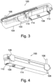
- Figure 3 is a further illustration of the condensate pump assembly shown in Figures 1 and 2 , with the same portion of the housing shown transparent as in Figure 1 .
- Figure 3 shows the condensate pump assembly 100 from beneath, showing a base portion 124 of the liquid receptacle 108.
- the base portion 124 is substantially opaque such that a user cannot see contents of the liquid receptacle 108 through the base portion 124.
- the base portion 124 forms an outer surface of the condensate pump assembly 100.
- the liquid receptacle 108 is formed from plastics.
- the liquid receptacle in this example is formed from the same plastics material as the housing 104 of the condensate pump assembly 100.
- FIG 4 is a yet further illustration of the condensate pump assembly shown in Figures 1 to 3 , showing mounting portions of the condensate pump assembly.
- a first longitudinal side wall of the condensate pump assembly 100 is provided with a first mounting portion in the form of a first mounting point 126 and a second mounting portion in the form of a second mounting point 128.
- the first mounting point 126 and the second mounting point 128 are usable to affix the condensate pump assembly 100 to a wall of a room or building, below the air conditioning unit of the air conditioning system.
- the first mounting point 126 and the second mounting point 128 can be provided on a second longitudinal side wall of the condensate pump assembly 100, opposite the first longitudinal side wall, whereby to mount the condensate pump assembly 100 after rotation by 180 degrees about an axis aligned with a direction of gravity.
- the condensate pump assembly 100 can be mounted such that the liquid receptacle 108 is provided at either a left or a right side of the condensate pump assembly 100, when the condensate pump assembly 100 is mounted to a wall of the room or building containing the air conditioning unit. This is particularly useful in space-constrained environments where accessibility to the condensate pump assembly 100 may be difficult.
- the first mounting point 126 and the second mounting point 128 are formed from rubber to function as an anti-vibration mount, damping any vibration of the condensate pump assembly 100 caused by operation of the reciprocating pump 102.
- the liquid receptacle 108 can be released from the first position by operation of the resilient clips 112, 114 by either hand of the user.
- the same condensate pump assembly 100 can be mounted to the wall in either a first rotational position or a second rotational position, rotated by 180 degrees from the first rotational position about an axis aligned with a direction of gravity.
- the same condensate pump assembly 100 can also be operated by either hand of a user in each of the first and second rotational positions. This helps to reduce manufacturing costs, since only a single design of condensate pump assembly 100 need be produced, for a range of different room designs.
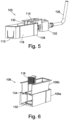
- FIG. 5 is an illustration showing internal components of the condensate pump assembly shown in Figures 1 to 4 .
- the condensate pump assembly 100 further comprises a liquid level sensor 130 configured to detect a liquid level in the liquid receptacle 108 when the liquid receptacle 108 is in the first position.
- the liquid level sensor 130 is a dip-sensor configured to output a signal indicative of the liquid level within the second reservoir 122 of the liquid receptacle 108 by being responsive to a covering of at least a portion of the liquid level sensor 130 by liquid in the second reservoir 122.
- the liquid level sensor 130 is a capacitive liquid level sensor 130 arranged to output a signal indicative of the liquid level within the second reservoir 122 of the liquid receptacle 108 based on a change in capacitance of the medium in contact with a portion of the liquid level sensor 130. It will be appreciated, however, that another type of liquid level sensor may be used instead.
- the condensate pump assembly 100 further comprises a pump controller (not shown).
- the pump controller may be implemented in hardware or software, or a combination of both.
- the pump controller is configured to operate the pump 102 when the liquid level sensor 130 outputs a first signal indicative of a liquid level within the liquid receptacle 108 at least a predetermined amount above a level of the open end of the liquid inlet 116 and to stop the pump 102 when the liquid level sensor 130 outputs a second signal indicative of a liquid level within the liquid receptacle 108 approaching or below a level of the liquid inlet 116.
- the pump controller is also configured to output a warning when the liquid level sensor 130 outputs a warning signal indicative of a liquid level within the liquid receptacle 130 above a predetermined warning level within the liquid receptacle 108.
- the air conditioning system is configured to stop operation of the air conditioning unit in response to the warning output.
- Figures 7, 8 and 9 illustrate an alternative embodiment.
- Figure 7 is a cross-sectional view of the liquid receptacle 200 of this alternative embodiment.
- An upper portion of the liquid receptacle 200 is open to receive condensate from an air conditioning unit (not shown) via the condensate inlet 110.
- the liquid receptacle 200 is shown having an inner wall 205 and an outer wall 210 sealed together to form an insulating gap 260 extending around substantially the entire outer surface of the inner wall 205.
- the insulating gap 260 is filled with air.
- other gaseous compositions or insulating material may be included within the insulating gap 260.
- a pair of support members 230 is also shown extending from the base surface 225 and configured to secure a filter 232 within the liquid receptacle 200.
- the filter 232 has a length along the surface of the filter 232 in a direction across the liquid receptacle 200 greater than the distance between the facing walls of the liquid receptacle 200.
- the filter 232 may be secured to the underside of an upper housing portion 107 or the base surface 225 of the liquid receptacle 200. A seal is formed between the upper housing portion 107 and housing 104 by a gasket 135. The filter 232 may be secured by slots or grooves within the surfaces that define the liquid receiving volume. This filter arrangement may be used in place of the filter arrangement of the embodiment illustrated in Figures 1 to 6 and vice versa.
- the liquid receptacle 200 is secured to the housing 104 by selective release means.
- the selective release means allows the liquid receptacle 200 to be movable from a first position, as shown in Figures 8 and 9 , to a second position removed from the housing 104.
- the selective release means may include a resilient clip 215 and a peg 235 at the opposite end of the liquid receptacle 200 configured, in use, to apply a force against the housing 104 to secure the liquid receptacle 200 when attached to the housing 104.
- the force may be applied against an inner surface 245 of the housing 104 via an outer surface 240 of the peg 235.
- the peg 235 used to secure the liquid receptacle 200 to the housing 105 may protrude through a cutaway 140.
- the illustrated arrangement allows a user to remove the liquid receptacle 200 from the housing 104, for example to clear the filter 232 of debris, by squeezing their thumb and finger together. This means a user is able to remove the liquid receptacle 200 using only a single hand. For example, the user is able to remove the liquid receptacle 200 by squeezing together their thumb and finger of their left or right hand. By enabling the removal of the liquid receptacle 200 with either hand, the flexibility of the present arrangement is further improved.
- the action of squeezing the thumb and finger together releases the resilient clip 215 from the housing 104 and releases a protrusion 220 of the resilient clip 215 from the corresponding recess 230 in the housing 104 (see also Figure 8 ) used to secure the liquid receptacle 200 in the housing 104.
- the resilient clip 215 can be disengaged from its respective lip, and in a single movement of the hand, release the liquid receptacle 200 for movement from the first position towards the second position.
- the movement of the liquid receptacle 200 after disengagement of the resilient clip 215 is substantially downwards in use.
- the selective release means is operable by any one of the hands of a user, and does not require both hands of a user, neither does such operation require one particular hand of the user. That is to say, the left or right hand of the user may be used to operate the selective release means.
- squeezing the resilient clip 215 and outer wall 210 also serves to grip the liquid receptacle 200 securely in the hand of a user, preventing accidental spillage of the contents thereof.
- the resilient clip 215 and outer wall 210 can be squeezed between a thumb and forefinger of the same hand for to release the liquid receptacle 200 from the first position.
- the outwardly biased resilient clip 215 and peg 235 exert a pressure against the respective corresponding recess 230 and inner wall 245, whereby to substantially prevent any rattle of the liquid receptacle 200 in the housing 104 when the liquid receptacle 200 is secured in the first position in the housing 104.
- the user's thumb or finger may be received by a slot 227 in the housing 104 to enhance the user's grip on the liquid receptacle 200 prior to squeezing the resilient clip 215.
- the outer wall 210 may have a protrusion 255 to further enhance the user's grip on the liquid receptacle 200.
- the thumb or finger of a user may rest on the protrusion 255 when removing the liquid receptacle 200 from the housing 104.
- the peg 235 may be stiffened by a support member 250 extending from the inner wall 205.
- the peg 235 may have a first longitudinal axis and the support member 250 may have a second longitudinal axis and the first longitudinal axis may be substantially parallel to the second longitudinal axis.
- the support member 250 may extend the length of the peg 235. While a resilient clip 215, in the form of a cantilever joint, and peg 235 are illustrated here, it would be apparent that other releasable joints may be used to secure the liquid receptacle 200. While a protrusion 255 in the form of a horizontal bar is illustrated in Figures 7 and 9 , it would be apparent that other arrangements to enhance the user's grip on the outer wall 210 are possible.
- Outer wall 210 may include one or more high friction materials to enhance the user's grip on the outer wall 210.
- the outer wall may include one or more rubberised sections.
- the outer wall may be made from one or more thermally insulating materials
- a condensate pump assembly (100) for use in an air conditioning system.
- the condensate pump assembly (100) comprises a pump (102) arranged in a housing (104) to pump liquid from a liquid inlet (116) towards a liquid outlet (106).
- the condensate pump assembly (100) further comprises a liquid receptacle (108) arranged, in a first position in the housing (104), to receive condensate from a condensate inlet (110) and to be in fluid communication with the liquid inlet (116).
- the liquid receptacle (108) is movable to a second position removed from the housing (104), whereby to empty the liquid receptacle (108).
- the condensate pump assembly (100) further comprises selective release (112, 114) means operable by a hand of a user to release the liquid receptacle (108) for movement from the first position towards the second position.
- the release means is operable by squeezing a thumb of the hand towards a finger of the hand.
Landscapes
- Engineering & Computer Science (AREA)
- Mechanical Engineering (AREA)
- General Engineering & Computer Science (AREA)
- Chemical & Material Sciences (AREA)
- Combustion & Propulsion (AREA)
- Details Of Reciprocating Pumps (AREA)
- Devices For Blowing Cold Air, Devices For Blowing Warm Air, And Means For Preventing Water Condensation In Air Conditioning Units (AREA)
- Structures Of Non-Positive Displacement Pumps (AREA)
Description
- This invention relates to a condensate pump assembly for use in an air conditioning system and a kit of parts for forming the same.
- Condensate pump assemblies are used to pump liquid condensate from appliances that produce condensate, for example an air conditioning system, a condensing boiler system or a refrigerator, out of a room or building. In a typical air conditioning system, the air conditioning unit produces liquid condensate, i.e. water, which drains from the air conditioning unit to a liquid reservoir in the form of a liquid receptacle in a condensate pump assembly mounted to a wall of the room or building, typically below the air conditioning unit. When the liquid receptacle is sufficiently filled with liquid, the liquid is pumped from the liquid receptacle via a liquid inlet and away from the condensate pump assembly, for example outside the room, via a liquid outlet. After sustained operation of the condensate pump assembly, contaminants such as dirt may enter the liquid receptacle and are not removed by the pump. The liquid receptacle can be made removable from a housing of the condensate pump assembly to allow cleaning of contaminants from the liquid receptacle.
- In condensate pump assemblies of the prior art, a clam-shell cover is affixed to the condensate pump assembly to secure the liquid receptacle in place in the condensate pump assembly, as well as to act as a sheath to improve the aesthetic appearance of the condensate pump assembly by hiding the liquid receptacle from view. Not only do such covers require two hands to remove, they also increase the size of the condensate pump assembly and create an additional source of noise by rattling against a housing of the condensate pump assembly during operation of the pump.
US 2016/0131372 A1 discloses an appliance for dehumidification having a water container detachably provided at an upper portion of a body of the appliance, the water container being easily separated from the appliance to empty the water container and being easily mounted again. - The present invention seeks to provide at least an alternative to condensate pump assemblies of the prior art.
- In accordance with the present invention there is provided a condensate pump assembly for use in an air conditioning system as defined in claim 1.
- The condensate pump assembly comprises, in particular, a pump arranged in a housing to pump liquid from a liquid inlet towards a liquid outlet. The condensate pump assembly further comprises a liquid receptacle arranged, in a first position in the housing, to receive condensate from a condensate inlet and to be in fluid communication with the liquid inlet. The liquid receptacle is movable to a second position removed from the housing, whereby to empty the liquid receptacle. The condensate pump assembly further comprises selective release means operable by a hand of a user to release the liquid receptacle for movement from the first position towards the second position. According to the invention, the release means is operable by squeezing a thumb of the hand towards a finger of the hand.
- Thus, the liquid receptacle of the condensate pump assembly can be removed from the housing for emptying without requiring a two-handed operation. This is useful because the condensate pump assembly can sometimes be mounted in confined or difficult to reach locations, where it may be difficult to access the liquid receptacle. One-handed operation of the selective release means allows the user to easily move the liquid receptacle from the first position towards the second position for emptying or cleaning of the liquid receptacle. The selective release means is operable one-handed by the user to release the liquid receptacle for movement from the first position towards the second position. It will be understood that the term one-handed does not require one particular hand of the user and in some embodiments, the user may use either hand to operate the selective release means.
- The release means may comprise a resilient member biased to hold the liquid receptacle in the first position and movable to release the liquid receptacle for movement from the first position towards the second position.
- The resilient member may be provided on the liquid receptacle. The resilient member may be biased to engage with a corresponding lip provided on the housing.
- The liquid receptacle may be secured in the first position only by the selective release means.
- The selective release means may be operable from a base surface of the condensate pump assembly, when the condensate pump assembly is mounted for use.
- A base portion of the liquid receptacle may provide an outer surface of the condensate pump assembly. Thus, the condensate pump assembly need not be provided with a removable cover. The lack of a removable cover reduces the noise of the condensate pump assembly from rattling during operation of the pump, unlike condensate pump assemblies of the prior art. Furthermore, the condensate pump assembly has fewer components since the liquid receptacle and the housing of the condensate pump assembly cooperate to hold the liquid receptacle in the first position, without also requiring a removable cover.
- The housing may comprise a shroud portion extending over a side wall of the liquid receptacle, whereby to hide the side wall of the liquid receptacle from view when the liquid receptacle is in the first position in the housing. The shroud portion may extend over all side walls of the liquid receptacle. Thus, a separate removable cover of the condensate pump assembly is not required for aesthetic reasons to hide the liquid receptacle from view when in the first position in the housing.
- The selective release means may comprise at least one snap-fit joint. The selective release means may comprise a resilient member biased to hold the liquid receptacle in the first position and movable to release the liquid receptacle for movement from the first position towards the second position. The selective release means may comprise a peg member configured, in use, to apply a force against the housing to secure the liquid receptacle when attached to the housing.
- The selective release means may comprise a resilient member biased to hold the liquid receptacle in the first position and movable to release the liquid receptacle for movement from the first position towards the second position.
- The liquid receptacle may comprise a support member configured to resist bending of the peg member.
- The release means may be operable by either hand of the user. Thus, the condensate pump assembly may be mountable to a wall surface in either of two rotational positions, spaced by 180 degrees, depending on the particular space availability in the vicinity of a connected air conditioning unit. The release means can be operated whether the condensate pump assembly is mounted in a first configuration, or a second configuration, rotated by 180 degrees relative to the first configuration about an axis aligned with a direction of gravity in use. This means the same tooling can be used to produce at least some components of the condensate pump assembly which are suitable for use in either of the first configuration or the second configuration.
- The release means is operable by squeezing. The release means is operable by squeezing a thumb of the hand towards a finger of the hand. Thus, the liquid receptacle can be easily removed and can be gripped with one hand as part of operating the release mechanism to prevent any spillage during movement of the liquid receptacle from the first position towards the second position.
- A shroud portion of the housing may be substantially opaque. Thus, the liquid receptacle can be substantially hidden from view in the first position. A base portion of the liquid receptacle may be substantially opaque.
- The pump may be a reciprocating pump. It will be appreciated that other types of pump may instead be used, such as a centrifugal pump. However, vibration of the condensate pump assembly is typically more of a problem with a reciprocating pump than with other types of pump.
- The housing may comprise at least one mounting point for mounting the condensate pump assembly to a wall. An axis of reciprocation of the reciprocating pump may be arranged to be substantially parallel to the wall when the condensate pump assembly is mounted to the wall. In embodiments, the housing may comprise a plurality of mounting points for mounting the condensate pump assembly in either of a first configuration, or a second configuration, the second configuration being rotated by 180 degrees relative to the first configuration about an axis aligned with a direction of gravity when the condensate pump assembly is mounted to the wall.
- The condensate pump assembly may further comprise a liquid level sensor configured to detect a liquid level in the liquid receptacle when the liquid receptacle is in the first position. The condensate pump assembly may further comprise a pump controller configured to operate the pump when the liquid level sensor outputs a first signal indicative of a liquid level within the liquid receptacle above a level of the liquid inlet to the pump and to stop the pump when the liquid level sensor outputs a second signal indicative of a liquid level within the liquid receptacle approaching or below a level of the liquid inlet to the pump.
- The liquid receptacle may comprise a filter to separate a first reservoir from a second reservoir, wherein the condensate inlet is arranged to provide liquid into the first reservoir and the liquid inlet is in fluid communication with the first reservoir via the filter and the second reservoir.
- Thus, any contaminants (such as dirt) unable to pass through the filter will remain in the first reservoir and will not be transferred to the second reservoir through the filter. This ensures that contaminants do not enter the pump and cause damage.
- The liquid receptacle may comprise a weir in the first reservoir and extending from a base portion of the liquid receptacle. Thus, any contaminants in the condensate liquid having a density greater than a bulk density of the condensate liquid will be caught by the weir and will not even encounter the filter. In embodiments, the liquid receptacle may comprise a weir in each of the first reservoir and the second reservoir.
- The liquid receptacle may be formed from an inner portion and an outer portion, whereby to provide a double-walled thermally insulated liquid receptacle. The inner portion may be slidably removable from the outer portion.
- The filter may be formed from a resilient material, and flexible such that the filter may be secured, in a bowed configuration, within either the inner portion of the liquid receptacle or the outer portion of the liquid receptacle. Thus, the same filter can be used for condensate pump assemblies both with and without the inner portion of the liquid receptacle.
- The present invention also provides a kit of parts for assembling a condensate pump assembly as defined in claim 15. The kit of parts comprises, in particular:
a housing; a pump to be arranged in the housing and operable to pump liquid from a liquid inlet towards a liquid outlet; and a liquid receptacle for insertion into a first position in the housing to receive condensate from a condensate inlet of the housing and to be in fluid communication with the liquid inlet. The liquid receptacle is movable from the first position into a second position, removed from the housing, whereby to empty the liquid receptacle. One or both of the housing or the liquid receptacle comprise selective release means operable by a hand of a user to release the liquid receptacle for movement from the first position towards the second position. The release means is operable by squeezing a thumb of the hand towards a finger of the hand - Embodiments of the invention are further described hereinafter with reference to the accompanying drawings, in which:
-
Figure 1 is an illustration of a condensate pump assembly with a portion of the housing shown transparent; -
Figure 2 is a cross-sectional view of the condensate pump assembly shown inFigure 1 ; -
Figure 3 is a further illustration of the condensate pump assembly shown inFigures 1 and 2 , with the same portion of the housing shown transparent as inFigure 1 ; -
Figure 4 is a yet further illustration of the condensate pump assembly shown inFigures 1 to 3 , showing mounting portions of the condensate pump assembly; and -
Figure 5 is an illustration showing internal components of the condensate pump assembly shown inFigures 1 to 4 ; -
Figure 6 is an exploded cross-sectional view of the liquid receptacle shown in the condensate pump assembly shown inFigures 1 to 5 ; -
Figure 7 ; is a cross-sectional view of an alternative liquid receptacle according to another embodiment; -
Figure 8 ; is a cross-sectional view of the liquid receptacle end of the condensate pump assembly, showing the liquid receptacle ofFig. 7 clipped in position; and -
Figure 9 is a top perspective view of the receptacle end of the condensate pump assembly, showing the liquid receptacle ofFig. 7 clipped in position. -
Figure 1 is an illustration of a condensate pump assembly with a portion of the housing shown transparent. Thecondensate pump assembly 100 comprises ahousing 104 to contain a pump in the form of a reciprocating pump 102 (not shown inFigure 1 ) mounted within ananti-vibration motor mount 103. Theanti-vibration motor mount 103 is typically formed from rubber. Thus, theanti-vibration motor mount 103 damps vibration in thecondensate pump assembly 100 caused by operation of thereciprocating pump 102. It will be understood that thereciprocating pump 102 may be damped in other ways, for example through other components connecting thereciprocating pump 102 to thehousing 104 of thecondensate pump assembly 100. In some examples, thereciprocating pump 102 need not use any damping. Thehousing 104 is typically formed from plastics. Thereciprocating pump 102 is arranged to pump liquid from a liquid inlet (not shown inFigure 1 ) to aliquid outlet 106. Thereciprocating pump 102 is a well-known pump and the skilled person would readily understand how to provide such a pump. A reciprocating axis of thereciprocating pump 102 is aligned with a longitudinal direction of thecondensate pump assembly 100. Thus, a height and a depth (distance away from the wall when mounted) of thecondensate pump assembly 100 can be small. When thecondensate pump assembly 100 is installed as part of an air conditioning system, theliquid outlet 106 is in fluid communication with a liquid drain (not shown) so that excess liquid can be removed from the air conditioning system. - The
condensate pump assembly 100 further comprises a liquid receptacle in the form of an open-topped,rectangular container 108. Thecontainer 108 comprises a base portion and four walls (not labelled inFigure 1 ). An upper portion of thecontainer 108 is open to receive condensate from an air conditioning unit (not shown) via acondensate inlet 110. In this example, thecondensate inlet 110 is defined by an opening in an upper surface of thehousing 104. Theliquid receptacle 108 is movable from a first position, as shown inFigure 1 , to a second position removed from thehousing 104. In the first position, theliquid receptacle 108 is provided at a first longitudinal end of thecondensate pump assembly 100, opposite an end of thecondensate pump assembly 100 having thereciprocating pump 102 and theliquid outlet 106. In the second position, theliquid receptacle 108 can be cleaned or emptied of liquid to remove any contaminants from theliquid receptacle 108. Thecondensate pump assembly 100 further comprises selective release means in the form of a firstresilient clip 112 and a second resilient clip (not shown inFigure 1 ). Theresilient clips liquid receptacle 108 for movement from the first position towards the second position. The operation and function of the selective release means will be described further in relation toFigures 2 and3 below. -
Figure 2 is a cross-sectional view of the condensate pump assembly shown inFigure 1 . The cross-sectional view of thecondensate pump assembly 100 is taken through a vertical plane aligned along a longitudinal axis of thecondensate pump assembly 100. Thus, it is possible to illustrate an internal pathway for liquid from thecondensate inlet 110 to theliquid outlet 106 via theliquid receptacle 108, aliquid inlet 116 and thereciprocating pump 102. As will be appreciated fromFigure 2 , and also fromFigure 6 , described in more detail below, theliquid receptacle 108 in this example, is insulated. In particular, theliquid receptacle 108 is formed from a double walled construction, comprising anouter portion 109a and aninner portion 109b. Theinner portion 109b is arranged to be removably and slidably mounted within theouter portion 109a. Thus, the double walled construction provides thermal insulation of any contents within theliquid receptacle 108 from an external environment of thecondensate pump assembly 100. This prevents formation of condensation on an outer surface of thehousing 104 of the condensate pump assembly, particularly in hot and/or humid environments where the temperature difference between thehousing 104 and the condensate within theliquid receptacle 108 may be significant. If condensation were to form, this may drip off thehousing 104 and be unsightly and unhygienic. In some examples, it will be understood that theouter portion 109a only of theliquid receptacle 108 may be provided, where insulation is not required (for example in cooler and/or drier environments. When theliquid receptacle 108 is provided in the first position, as shown inFigure 2 , theliquid receptacle 108 is in thehousing 104 and can receive condensate from thecondensate inlet 110. Theliquid receptacle 108, in the first position, is also in fluid communication with theliquid inlet 116. In use, liquid, typically condensate water from the air conditioning unit, enters theliquid receptacle 108 through a drainage tube (not shown) connected to thecondensate inlet 110. The liquid enters afirst reservoir 120 defined by an internal wall of theliquid receptacle 108 and afilter 118. Theliquid receptacle 108 is also illustrated in the exploded cross-section view shown inFigure 6 . Thefilter 118 has a length along the surface of the filter in a direction across theliquid receptacle 108 greater than the distance between the facing walls of theliquid receptacle 108. This ensures that the cross-sectional area of thefilter 118 is greater than the cross-sectional area of the distance directly across theliquid receptacle 108 whereby to improve the capacity of thefilter 118. In this example, thefilter 118 is formed from a resilient material and has a curved shape relative to thefirst reservoir 120 and an overturned lip at a free end thereof. The resilient material and curved shape of thefilter 118 allows thesame filter 118 to be used regardless of whether theliquid receptacle 108 comprises theouter portion 109a and theinner portion 109b, or just theouter portion 109a. Thefilter 118 ensures any particulates in the condensate received from thecondensate inlet 110 do not pass to theliquid inlet 116 and onwards to thereciprocating pump 102. In this example, thefilter 118 is porous to particles of less than 0.9 millimetre in diameter, and is provided by a filter member having a plurality of holes defined therein, each hole having a diameter of approximately 0.9 millimetres. It will be understood that other filter types and/or hole sizes may be used. The overturned lip can be used as a handle to easily remove and insert thefilter 118 relative to theliquid receptacle 108, for cleaning and/or replacement. In this example, thefilter 118 is convexly curved relative to thefirst reservoir 120 and the overturned lip extends towards thefirst reservoir 120. However, it will be understood that thefilter 118 may alternatively have a concave shape relative to thefirst reservoir 120. Thefilter 118 separates thefirst reservoir 120 from asecond reservoir 122. In this way, thefirst reservoir 120 is in fluid communication with thesecond reservoir 122 via thefilter 118. In this example, thefilter 118 has a concave shape relative to thesecond reservoir 122 and the overturned lip at the free end thereof, extends away from thesecond reservoir 122. However, as above, it will be understood that thefilter 118 may alternatively have a convex shape relative to thesecond reservoir 122. Thesecond reservoir 122 is downstream of thefirst reservoir 120, arranged to contain liquid received from thecondensate inlet 110 and filtered by thefilter 118. - The
liquid receptacle 108 is also provided with aweir outer portion 109a and theinner portion 109b of theliquid receptacle 108 is provided with aweir weirs inner portion 109b can be mounted within theouter portion 109a without significant reduction of the available volume of theliquid receptacle 108. It will be understood that the height of theweirs weirs weirs outer portion 109a and theinner portion 109b respectively. It will be understood that a different number and/or shape ofweirs weirs filter 118. Theweirs reciprocating pump 102. - In this way, none, or at least very few foreign objects or contaminants from the air conditioning unit pass to the
second reservoir 122 of theliquid receptacle 108. Theliquid inlet 116 is formed from a hollow tube having an open end and extending substantially downwards within thesecond reservoir 122 to a depth below a height of thefilter 118. The hollow tube enters thesecond reservoir 122 of theliquid receptacle 108 through an open upper portion of theliquid receptacle 108. In this example, the open end of theliquid inlet 116 extends to a position over half of the height of thefilter 118. Thus, theliquid inlet 116 can extract liquid from theliquid receptacle 108 up to a depth of the open end of theliquid inlet 116. The hollow tube forming theliquid inlet 116 is connected, at an end opposite the open end, to thereciprocating pump 102. On operation of thereciprocating pump 102, the liquid is drawn from thesecond reservoir 122 of theliquid receptacle 108 via theliquid inlet 116. The liquid is pumped out of thecondensate pump assembly 100 through theliquid outlet 106 by thereciprocating pump 102. Operation of thereciprocating pump 102 of thecondensate pump assembly 100 is explained more fully with reference toFigure 5 below. - The
liquid receptacle 108 can be released from the first position for movement towards the second position by operation of the selective release means in the form of the a firstresilient member 112 and a secondresilient member 114. Theresilient members liquid receptacle 108 in the first position within thehousing 104. In particular, theresilient members resilient clip 112 and a secondresilient clip 114 connected to a side wall of theliquid receptacle 108 and extending towards a base surface of thecondensate pump assembly 100. Each of theresilient clips housing 104, whereby to secure theliquid receptacle 108 in the first position in thehousing 104. The outwardly biasedresilient clips housing 104, whereby to substantially prevent any rattle of theliquid receptacle 108 in thehousing 104 when the liquid receptacle is secured in the first position in thehousing 104. In effect, theresilient clips liquid receptacle 108 in thehousing 104. Afinger recess 115 is defined in a base surface of thehousing 104, whereby to allow a finger or thumb of a user to engage with an outer side of the secondresilient clip 114. By squeezing theresilient clips resilient clips liquid receptacle 108 for movement from the first position towards the second position. The movement of theliquid receptacle 108 after disengagement of theresilient clips housing 104 is substantially downwards in use. It will be understood that the selective release means is operable by any one of the hands of a user, and does not require both hands of a user, neither does such operation require one particular hand of the user. Furthermore, squeezing theresilient clips liquid receptacle 108 securely in the hand of a user, preventing accidental spillage of the contents thereof. In the present example, theresilient clips liquid receptacle 108 from the first position. - In this example, it will be appreciated that the
liquid receptacle 108 is symmetric about a plane of symmetry across theliquid receptacle 108 and transverse to a direction of liquid flow through theliquid receptacle 108. Thus, theliquid receptacle 108 can be mounted within thehousing 102 in one of two rotational positions. -
Figure 3 is a further illustration of the condensate pump assembly shown inFigures 1 and 2 , with the same portion of the housing shown transparent as inFigure 1 . In particular,Figure 3 shows thecondensate pump assembly 100 from beneath, showing abase portion 124 of theliquid receptacle 108. Thebase portion 124 is substantially opaque such that a user cannot see contents of theliquid receptacle 108 through thebase portion 124. Furthermore, thebase portion 124 forms an outer surface of thecondensate pump assembly 100. In normal operation of thecondensate pump assembly 100 when connected to an air conditioning unit, no additional cover is required to support and hide theliquid receptacle 108. In this example, theliquid receptacle 108 is formed from plastics. The liquid receptacle in this example is formed from the same plastics material as thehousing 104 of thecondensate pump assembly 100. -
Figure 4 is a yet further illustration of the condensate pump assembly shown inFigures 1 to 3 , showing mounting portions of the condensate pump assembly. A first longitudinal side wall of thecondensate pump assembly 100 is provided with a first mounting portion in the form of afirst mounting point 126 and a second mounting portion in the form of asecond mounting point 128. Thefirst mounting point 126 and thesecond mounting point 128 are usable to affix thecondensate pump assembly 100 to a wall of a room or building, below the air conditioning unit of the air conditioning system. Alternatively, thefirst mounting point 126 and thesecond mounting point 128 can be provided on a second longitudinal side wall of thecondensate pump assembly 100, opposite the first longitudinal side wall, whereby to mount thecondensate pump assembly 100 after rotation by 180 degrees about an axis aligned with a direction of gravity. In this way, thecondensate pump assembly 100 can be mounted such that theliquid receptacle 108 is provided at either a left or a right side of thecondensate pump assembly 100, when thecondensate pump assembly 100 is mounted to a wall of the room or building containing the air conditioning unit. This is particularly useful in space-constrained environments where accessibility to thecondensate pump assembly 100 may be difficult. In this example, thefirst mounting point 126 and thesecond mounting point 128 are formed from rubber to function as an anti-vibration mount, damping any vibration of thecondensate pump assembly 100 caused by operation of thereciprocating pump 102. Furthermore, as has been explained above, theliquid receptacle 108 can be released from the first position by operation of theresilient clips condensate pump assembly 100 can be mounted to the wall in either a first rotational position or a second rotational position, rotated by 180 degrees from the first rotational position about an axis aligned with a direction of gravity. The samecondensate pump assembly 100 can also be operated by either hand of a user in each of the first and second rotational positions. This helps to reduce manufacturing costs, since only a single design ofcondensate pump assembly 100 need be produced, for a range of different room designs. -
Figure 5 is an illustration showing internal components of the condensate pump assembly shown inFigures 1 to 4 . Thecondensate pump assembly 100 further comprises aliquid level sensor 130 configured to detect a liquid level in theliquid receptacle 108 when theliquid receptacle 108 is in the first position. In this example, theliquid level sensor 130 is a dip-sensor configured to output a signal indicative of the liquid level within thesecond reservoir 122 of theliquid receptacle 108 by being responsive to a covering of at least a portion of theliquid level sensor 130 by liquid in thesecond reservoir 122. In this example, theliquid level sensor 130 is a capacitiveliquid level sensor 130 arranged to output a signal indicative of the liquid level within thesecond reservoir 122 of theliquid receptacle 108 based on a change in capacitance of the medium in contact with a portion of theliquid level sensor 130. It will be appreciated, however, that another type of liquid level sensor may be used instead. - The
condensate pump assembly 100 further comprises a pump controller (not shown). The pump controller may be implemented in hardware or software, or a combination of both. The pump controller is configured to operate thepump 102 when theliquid level sensor 130 outputs a first signal indicative of a liquid level within theliquid receptacle 108 at least a predetermined amount above a level of the open end of theliquid inlet 116 and to stop thepump 102 when theliquid level sensor 130 outputs a second signal indicative of a liquid level within theliquid receptacle 108 approaching or below a level of theliquid inlet 116. The pump controller is also configured to output a warning when theliquid level sensor 130 outputs a warning signal indicative of a liquid level within theliquid receptacle 130 above a predetermined warning level within theliquid receptacle 108. The air conditioning system is configured to stop operation of the air conditioning unit in response to the warning output. -
Figures 7, 8 and9 illustrate an alternative embodiment.Figure 7 is a cross-sectional view of theliquid receptacle 200 of this alternative embodiment. An upper portion of theliquid receptacle 200 is open to receive condensate from an air conditioning unit (not shown) via thecondensate inlet 110. Theliquid receptacle 200 is shown having aninner wall 205 and anouter wall 210 sealed together to form an insulatinggap 260 extending around substantially the entire outer surface of theinner wall 205. By surrounding theinner wall 205 the insulatinggap 260, the insulating effects are maximised and the risk of condensate forming on the outer surface of theouter wall 210 is minimised. Preferably the insulatinggap 260 is filled with air. However, other gaseous compositions or insulating material may be included within the insulatinggap 260. - A pair of
support members 230 is also shown extending from thebase surface 225 and configured to secure afilter 232 within theliquid receptacle 200. By placing thefilter 232 in the fluid flow path between the fluid inlet and the pump and securing thefilter 232 such that thefilter 232 extends across the width of the liquid receptacle, larger particulate debris can be prevented from reaching thepump 102. Thefilter 232 has a length along the surface of thefilter 232 in a direction across theliquid receptacle 200 greater than the distance between the facing walls of theliquid receptacle 200. This ensures that the cross-sectional area of thefilter 232 is greater than the cross-sectional area of the distance directly across theliquid receptacle 200 whereby to improve the capacity of thefilter 232. While thefilter 232 is shown comprising a plurality of circular holes, it would be apparent that other shapes of holes may be used. While a pair ofsupports members 230 have been shown, it would be apparent that other arrangements may be used to secure thefilter 232. Such arrangements may include more or fewer than two extendingmembers 230. Thefilter 232 may be secured to the underside of anupper housing portion 107 or thebase surface 225 of theliquid receptacle 200. A seal is formed between theupper housing portion 107 andhousing 104 by agasket 135. Thefilter 232 may be secured by slots or grooves within the surfaces that define the liquid receiving volume. This filter arrangement may be used in place of the filter arrangement of the embodiment illustrated inFigures 1 to 6 and vice versa. - The
liquid receptacle 200 is secured to thehousing 104 by selective release means. The selective release means allows theliquid receptacle 200 to be movable from a first position, as shown inFigures 8 and9 , to a second position removed from thehousing 104. As shown inFigure 7 , the selective release means may include aresilient clip 215 and apeg 235 at the opposite end of theliquid receptacle 200 configured, in use, to apply a force against thehousing 104 to secure theliquid receptacle 200 when attached to thehousing 104. The force may be applied against aninner surface 245 of thehousing 104 via anouter surface 240 of thepeg 235. Thepeg 235 used to secure theliquid receptacle 200 to the housing 105 may protrude through acutaway 140. The illustrated arrangement allows a user to remove theliquid receptacle 200 from thehousing 104, for example to clear thefilter 232 of debris, by squeezing their thumb and finger together. This means a user is able to remove theliquid receptacle 200 using only a single hand. For example, the user is able to remove theliquid receptacle 200 by squeezing together their thumb and finger of their left or right hand. By enabling the removal of theliquid receptacle 200 with either hand, the flexibility of the present arrangement is further improved. The action of squeezing the thumb and finger together releases theresilient clip 215 from thehousing 104 and releases aprotrusion 220 of theresilient clip 215 from thecorresponding recess 230 in the housing 104 (see alsoFigure 8 ) used to secure theliquid receptacle 200 in thehousing 104. By squeezing theresilient clip 215 andouter wall 210 using opposing digits on a hand of a user, theresilient clip 215 can be disengaged from its respective lip, and in a single movement of the hand, release theliquid receptacle 200 for movement from the first position towards the second position. The movement of theliquid receptacle 200 after disengagement of theresilient clip 215 is substantially downwards in use. It will be understood that the selective release means is operable by any one of the hands of a user, and does not require both hands of a user, neither does such operation require one particular hand of the user. That is to say, the left or right hand of the user may be used to operate the selective release means. Furthermore, squeezing theresilient clip 215 andouter wall 210 also serves to grip theliquid receptacle 200 securely in the hand of a user, preventing accidental spillage of the contents thereof. In the present example, theresilient clip 215 andouter wall 210 can be squeezed between a thumb and forefinger of the same hand for to release theliquid receptacle 200 from the first position. The outwardly biasedresilient clip 215 and peg 235 exert a pressure against the respectivecorresponding recess 230 andinner wall 245, whereby to substantially prevent any rattle of theliquid receptacle 200 in thehousing 104 when theliquid receptacle 200 is secured in the first position in thehousing 104. The user's thumb or finger may be received by aslot 227 in thehousing 104 to enhance the user's grip on theliquid receptacle 200 prior to squeezing theresilient clip 215. Theouter wall 210 may have aprotrusion 255 to further enhance the user's grip on theliquid receptacle 200. The thumb or finger of a user may rest on theprotrusion 255 when removing theliquid receptacle 200 from thehousing 104. Thepeg 235 may be stiffened by asupport member 250 extending from theinner wall 205. Thepeg 235 may have a first longitudinal axis and thesupport member 250 may have a second longitudinal axis and the first longitudinal axis may be substantially parallel to the second longitudinal axis. Thesupport member 250 may extend the length of thepeg 235. While aresilient clip 215, in the form of a cantilever joint, and peg 235 are illustrated here, it would be apparent that other releasable joints may be used to secure theliquid receptacle 200. While aprotrusion 255 in the form of a horizontal bar is illustrated inFigures 7 and9 , it would be apparent that other arrangements to enhance the user's grip on theouter wall 210 are possible.Outer wall 210 may include one or more high friction materials to enhance the user's grip on theouter wall 210. For example, the outer wall may include one or more rubberised sections. The outer wall may be made from one or more thermally insulating materials, such as plastic. - In summary, there is provided a condensate pump assembly (100) for use in an air conditioning system. The condensate pump assembly (100) comprises a pump (102) arranged in a housing (104) to pump liquid from a liquid inlet (116) towards a liquid outlet (106). The condensate pump assembly (100) further comprises a liquid receptacle (108) arranged, in a first position in the housing (104), to receive condensate from a condensate inlet (110) and to be in fluid communication with the liquid inlet (116). The liquid receptacle (108) is movable to a second position removed from the housing (104), whereby to empty the liquid receptacle (108). The condensate pump assembly (100) further comprises selective release (112, 114) means operable by a hand of a user to release the liquid receptacle (108) for movement from the first position towards the second position. According to the invention, the release means is operable by squeezing a thumb of the hand towards a finger of the hand.
- Throughout the description and claims of this specification, the words "comprise" and "contain" and variations of them mean "including but not limited to", and they are not intended to (and do not) exclude other moieties, additives, components, integers or steps. Throughout the description and claims of this specification, the singular encompasses the plural unless the context otherwise requires. In particular, where the indefinite article is used, the specification is to be understood as contemplating plurality as well as singularity, unless the context requires otherwise.
Claims (15)
- A condensate pump assembly (100) for use in an air conditioning system, the condensate pump assembly (100) comprising:a pump (102) arranged in a housing (104) to pump liquid from a liquid inlet (116) towards a liquid outlet (106); anda liquid receptacle (108,200) arranged, in a first position in the housing (104), to receive condensate from a condensate inlet (110) and to be in fluid communicationwith the liquid inlet (116), the liquid receptacle (108,200) being movable to a secondposition removed from the housing (104), whereby to empty the liquid receptacle (108,200); andselective release means operable by a hand of a user to release the liquid receptacle (108,200) for movement from the first position towards the second position,characterised in thatthe release means is operable by squeezing a thumb of the hand towards a finger of the hand.
- A condensate pump assembly (100) as claimed in claim 1, wherein the release means comprises a resilient member (112,114,215) biased to hold the liquid receptacle (108,200) in the first position and movable to release the liquid receptacle (108,200) for movement from the first position towards the second position.
- A condensate pump assembly (100) as claimed in claim 2, wherein the resilient member (112,114,215) is provided on the liquid receptacle (108,200) and is biased to engage with a corresponding lip provided on the housing (104).
- A condensate pump assembly (100) as claimed in any preceding claim, wherein the liquid receptacle (108,200) is secured in the first position only by the selective release means.
- A condensate pump assembly (100) as claimed in any preceding claim, wherein the selective release means are operable from a base surface of the condensate pump assembly (100), when the condensate pump assembly (100) is mounted for use.
- A condensate pump assembly (100) as claimed in any preceding claim, wherein a base portion (124) of the liquid receptacle (108,200) provides an outer surface of the condensate pump assembly (100).
- A condensate pump assembly (100) as claimed in any preceding claim, wherein the housing (104) comprises a shroud portion extending over a side wall of the liquid receptacle (108,200), whereby to hide the side wall of the liquid receptacle (108,200) from view when the liquid receptacle (108,200) is in the first position in the housing (104).
- A condensate pump assembly (100) as claimed in claim 7, wherein the shroud portion extends over all side walls of the liquid receptacle (108,200).
- A condensate pump assembly (100) according to any preceding claim, wherein the selective release means comprises at least one snap-fit joint (220,230) at a first end of the liquid receptacle (108,200).
- A condensate pump assembly (100) according to any preceding claim, wherein the selective release means comprises a peg member (235) at a second end opposed to the first end of the liquid receptacle (200), and wherein the peg member (235) is configured, in use, to apply a force against the housing (104) to secure the liquid receptacle (200) when attached to the housing (104).
- A condensate pump assembly (100) according to claim 10, wherein the selective release means comprises a support member (250) configured to resist bending of the peg member (235).
- A condensate pump assembly (100) as claimed in any preceding claim, wherein the release means is operable by either hand of the user.
- A condensate pump assembly (100) as claimed in any preceding claim, wherein the pump is a reciprocating pump, and wherein the housing (104) comprises at least one mounting point (126,128) for mounting the condensate pump assembly (100) to a wall, and wherein an axis of reciprocation of the reciprocating pump (102) is arranged to be substantially parallel to the wall when the condensate pump assembly (100) is mounted to the wall.
- A condensate pump assembly (100) as claimed in any preceding claim, wherein the condensate pump assembly (100) further comprises a liquid level sensor (130) configured to detect a liquid level in the liquid receptacle (108,200) when the liquid receptacle (108,200) is in the first position; and a pump controller configured to operate the pump (102) when the liquid level sensor (130) outputs a first signal indicative of a liquid level within the liquid receptacle (108,200) above a level of the liquid inlet (116) to the pump (102) and to stop the pump (102) when the liquid level sensor (130) outputs a second signal indicative of a liquid level within the liquid receptacle (108,200) approaching or below a level of the liquid inlet (116) to the pump (102).
- A kit of parts for assembling a condensate pump assembly (100) comprising:a housing (104);a pump (102) to be arranged in the housing (102) and operable to pump liquid from a liquid inlet (116) towards a liquid outlet (106); anda liquid receptacle (108,200) for insertion into a first position in the housing (104) to receive condensate from a condensate inlet (110) of the housing (104) and to be in fluid communication with the liquid inlet (116), the liquid receptacle (108,200) being movable from the first position into a second position, removed from the housing (104), whereby to empty the liquid receptacle (108,200),wherein one or both of the housing (104) or the liquid receptacle (108,200) comprise selective release means operable by a hand of a user to release the liquid receptacle (108,200) for movement from the first position towards the second position, andcharacterised in thatthe release means is operable by squeezing a thumb of the hand towards a finger of the hand.
Applications Claiming Priority (2)
| Application Number | Priority Date | Filing Date | Title |
|---|---|---|---|
| GB1712431.4A GB2565112B (en) | 2017-08-02 | 2017-08-02 | Condensate pump assembly |
| PCT/GB2018/052119 WO2019025765A1 (en) | 2017-08-02 | 2018-07-27 | Condensate pump assembly |
Publications (2)
| Publication Number | Publication Date |
|---|---|
| EP3662209A1 EP3662209A1 (en) | 2020-06-10 |
| EP3662209B1 true EP3662209B1 (en) | 2023-04-19 |
Family
ID=59778736
Family Applications (1)
| Application Number | Title | Priority Date | Filing Date |
|---|---|---|---|
| EP18752230.5A Active EP3662209B1 (en) | 2017-08-02 | 2018-07-27 | Condensate pump assembly |
Country Status (6)
| Country | Link |
|---|---|
| US (1) | US11739977B2 (en) |
| EP (1) | EP3662209B1 (en) |
| CN (1) | CN111373210A (en) |
| AU (1) | AU2018309404A1 (en) |
| GB (1) | GB2565112B (en) |
| WO (1) | WO2019025765A1 (en) |
Families Citing this family (4)
| Publication number | Priority date | Publication date | Assignee | Title |
|---|---|---|---|---|
| GB2577818B (en) * | 2017-11-10 | 2020-09-23 | Aspen Pumps Ltd | Pumps |
| USD949202S1 (en) * | 2019-04-25 | 2022-04-19 | Aspen Pumps Limited | Fluid pump |
| EP3945212B1 (en) * | 2020-07-27 | 2024-04-03 | Aspen Pumps Limited | Condensate pump arrangement |
| GB2599094B (en) * | 2020-09-21 | 2024-11-20 | Charles Austen Pumps Ltd | A condensate tray assembly |
Family Cites Families (12)
| Publication number | Priority date | Publication date | Assignee | Title |
|---|---|---|---|---|
| US4554794A (en) * | 1984-06-20 | 1985-11-26 | Whirlpool Corporation | Condensate receptacle support for dehumidifier |
| US5188710A (en) * | 1991-01-18 | 1993-02-23 | Emerson Electric Co. | Continuous water distillation system |
| CN1506636A (en) * | 2002-12-06 | 2004-06-23 | 小巨人泵业公司 | Condensate liquid pump apparatus assemblied with standard parts |
| US20090071181A1 (en) | 2007-09-19 | 2009-03-19 | Spanger Gerald S | Evaporator unit |
| US8182243B2 (en) * | 2008-08-15 | 2012-05-22 | Diversitech Corporation | Condensate pump |
| US20110272043A1 (en) | 2010-04-15 | 2011-11-10 | Little Giant Pump Company Llc | Condensate removal system and method |
| CN202101381U (en) * | 2011-05-13 | 2012-01-04 | 苏州三星电子有限公司 | Air conditioner and drainage pump system thereof |
| KR102504092B1 (en) * | 2014-11-12 | 2023-02-28 | 삼성전자주식회사 | Appliance for dehumidification and multi-function appliance for dehumidification or humidification |
| US9726396B2 (en) * | 2015-05-15 | 2017-08-08 | Diversitech Corporation | Universal line components duct elbow |
| GB2544756A (en) * | 2015-11-24 | 2017-05-31 | Ebac Ind Products Ltd | Pump assembly incorporating a sump |
| CN106678977B (en) * | 2017-01-20 | 2022-04-05 | 广东美的制冷设备有限公司 | Air Conditioner Wall Mount and Air Conditioner |
| CN106931532B (en) * | 2017-04-27 | 2019-11-22 | 海信家电集团股份有限公司 | a dehumidifier |
-
2017
- 2017-08-02 GB GB1712431.4A patent/GB2565112B/en active Active
-
2018
- 2018-07-27 US US16/635,737 patent/US11739977B2/en active Active
- 2018-07-27 EP EP18752230.5A patent/EP3662209B1/en active Active
- 2018-07-27 WO PCT/GB2018/052119 patent/WO2019025765A1/en not_active Ceased
- 2018-07-27 CN CN201880057248.8A patent/CN111373210A/en active Pending
- 2018-07-27 AU AU2018309404A patent/AU2018309404A1/en not_active Abandoned
Also Published As
| Publication number | Publication date |
|---|---|
| GB2565112A (en) | 2019-02-06 |
| GB2565112B (en) | 2020-02-19 |
| AU2018309404A1 (en) | 2020-02-13 |
| GB201712431D0 (en) | 2017-09-13 |
| US20210131700A1 (en) | 2021-05-06 |
| US11739977B2 (en) | 2023-08-29 |
| WO2019025765A1 (en) | 2019-02-07 |
| CN111373210A (en) | 2020-07-03 |
| EP3662209A1 (en) | 2020-06-10 |
Similar Documents
| Publication | Publication Date | Title |
|---|---|---|
| US11739977B2 (en) | Condensate pump assembly | |
| EP3951225B1 (en) | A valve assembly and housing comprising the same | |
| CA2669056C (en) | Vacuum appliance filter assemblies and associated vacuum systems | |
| CN108348831B (en) | Filters and Steam Removal Units for Steam Removal Units | |
| US20140298612A1 (en) | Filter cage for wet/dry vacuums | |
| RU2007118380A (en) | A VACUUM CLEANER | |
| EP3028619B1 (en) | Robot cleaner | |
| JP5464343B2 (en) | Filter assembly | |
| KR20160044075A (en) | Straw cup | |
| CN111465768B (en) | Pump and method of operating the same | |
| EP3830493B1 (en) | Condensate pump assembly | |
| CN216262243U (en) | Recovery box and surface cleaning equipment | |
| CN115363490B (en) | Dirt Tank Assemblies, Maintenance Stations and Cleaning Systems | |
| KR102095234B1 (en) | Drain trap | |
| JP6319999B2 (en) | Method for manufacturing hair catcher structure | |
| JP4453381B2 (en) | Water storage device | |
| CN105143775B (en) | For the module of drawing-in type smoke exhaust ventilator cover | |
| CN216364865U (en) | Soap dispenser with detachable water tank | |
| GB2588052A (en) | Condensate pump assembly | |
| GB2588051A (en) | Condensate pump assembly | |
| CN217356997U (en) | Greasy dirt collection device, oil cup, lampblack absorber and lampblack absorber without oil cup | |
| KR101653317B1 (en) | Airtight Container | |
| US20050284301A1 (en) | Water cleaning dust-filtering device | |
| JP2008232450A (en) | Ventilation device | |
| EP4394267A1 (en) | Dehumidifier |
Legal Events
| Date | Code | Title | Description |
|---|---|---|---|
| STAA | Information on the status of an ep patent application or granted ep patent |
Free format text: STATUS: UNKNOWN |
|
| STAA | Information on the status of an ep patent application or granted ep patent |
Free format text: STATUS: THE INTERNATIONAL PUBLICATION HAS BEEN MADE |
|
| PUAI | Public reference made under article 153(3) epc to a published international application that has entered the european phase |
Free format text: ORIGINAL CODE: 0009012 |
|
| STAA | Information on the status of an ep patent application or granted ep patent |
Free format text: STATUS: REQUEST FOR EXAMINATION WAS MADE |
|
| 17P | Request for examination filed |
Effective date: 20200128 |
|
| AK | Designated contracting states |
Kind code of ref document: A1 Designated state(s): AL AT BE BG CH CY CZ DE DK EE ES FI FR GB GR HR HU IE IS IT LI LT LU LV MC MK MT NL NO PL PT RO RS SE SI SK SM TR |
|
| AX | Request for extension of the european patent |
Extension state: BA ME |
|
| DAV | Request for validation of the european patent (deleted) | ||
| DAX | Request for extension of the european patent (deleted) | ||
| GRAP | Despatch of communication of intention to grant a patent |
Free format text: ORIGINAL CODE: EPIDOSNIGR1 |
|
| STAA | Information on the status of an ep patent application or granted ep patent |
Free format text: STATUS: GRANT OF PATENT IS INTENDED |
|
| INTG | Intention to grant announced |
Effective date: 20221216 |
|
| GRAS | Grant fee paid |
Free format text: ORIGINAL CODE: EPIDOSNIGR3 |
|
| GRAA | (expected) grant |
Free format text: ORIGINAL CODE: 0009210 |
|
| STAA | Information on the status of an ep patent application or granted ep patent |
Free format text: STATUS: THE PATENT HAS BEEN GRANTED |
|
| AK | Designated contracting states |
Kind code of ref document: B1 Designated state(s): AL AT BE BG CH CY CZ DE DK EE ES FI FR GB GR HR HU IE IS IT LI LT LU LV MC MK MT NL NO PL PT RO RS SE SI SK SM TR |
|
| REG | Reference to a national code |
Ref country code: GB Ref legal event code: FG4D |
|
| REG | Reference to a national code |
Ref country code: DE Ref legal event code: R096 Ref document number: 602018048600 Country of ref document: DE |
|
| REG | Reference to a national code |
Ref country code: CH Ref legal event code: EP |
|
| REG | Reference to a national code |
Ref country code: IE Ref legal event code: FG4D |
|
| REG | Reference to a national code |
Ref country code: AT Ref legal event code: REF Ref document number: 1561463 Country of ref document: AT Kind code of ref document: T Effective date: 20230515 |
|
| REG | Reference to a national code |
Ref country code: LT Ref legal event code: MG9D |
|
| REG | Reference to a national code |
Ref country code: NL Ref legal event code: MP Effective date: 20230419 |
|
| REG | Reference to a national code |
Ref country code: AT Ref legal event code: MK05 Ref document number: 1561463 Country of ref document: AT Kind code of ref document: T Effective date: 20230419 |
|
| PG25 | Lapsed in a contracting state [announced via postgrant information from national office to epo] |
Ref country code: NL Free format text: LAPSE BECAUSE OF FAILURE TO SUBMIT A TRANSLATION OF THE DESCRIPTION OR TO PAY THE FEE WITHIN THE PRESCRIBED TIME-LIMIT Effective date: 20230419 |
|
| PG25 | Lapsed in a contracting state [announced via postgrant information from national office to epo] |
Ref country code: SE Free format text: LAPSE BECAUSE OF FAILURE TO SUBMIT A TRANSLATION OF THE DESCRIPTION OR TO PAY THE FEE WITHIN THE PRESCRIBED TIME-LIMIT Effective date: 20230419 Ref country code: PT Free format text: LAPSE BECAUSE OF FAILURE TO SUBMIT A TRANSLATION OF THE DESCRIPTION OR TO PAY THE FEE WITHIN THE PRESCRIBED TIME-LIMIT Effective date: 20230821 Ref country code: NO Free format text: LAPSE BECAUSE OF FAILURE TO SUBMIT A TRANSLATION OF THE DESCRIPTION OR TO PAY THE FEE WITHIN THE PRESCRIBED TIME-LIMIT Effective date: 20230719 Ref country code: ES Free format text: LAPSE BECAUSE OF FAILURE TO SUBMIT A TRANSLATION OF THE DESCRIPTION OR TO PAY THE FEE WITHIN THE PRESCRIBED TIME-LIMIT Effective date: 20230419 Ref country code: AT Free format text: LAPSE BECAUSE OF FAILURE TO SUBMIT A TRANSLATION OF THE DESCRIPTION OR TO PAY THE FEE WITHIN THE PRESCRIBED TIME-LIMIT Effective date: 20230419 |
|
| PG25 | Lapsed in a contracting state [announced via postgrant information from national office to epo] |
Ref country code: RS Free format text: LAPSE BECAUSE OF FAILURE TO SUBMIT A TRANSLATION OF THE DESCRIPTION OR TO PAY THE FEE WITHIN THE PRESCRIBED TIME-LIMIT Effective date: 20230419 Ref country code: PL Free format text: LAPSE BECAUSE OF FAILURE TO SUBMIT A TRANSLATION OF THE DESCRIPTION OR TO PAY THE FEE WITHIN THE PRESCRIBED TIME-LIMIT Effective date: 20230419 Ref country code: LV Free format text: LAPSE BECAUSE OF FAILURE TO SUBMIT A TRANSLATION OF THE DESCRIPTION OR TO PAY THE FEE WITHIN THE PRESCRIBED TIME-LIMIT Effective date: 20230419 Ref country code: LT Free format text: LAPSE BECAUSE OF FAILURE TO SUBMIT A TRANSLATION OF THE DESCRIPTION OR TO PAY THE FEE WITHIN THE PRESCRIBED TIME-LIMIT Effective date: 20230419 Ref country code: IS Free format text: LAPSE BECAUSE OF FAILURE TO SUBMIT A TRANSLATION OF THE DESCRIPTION OR TO PAY THE FEE WITHIN THE PRESCRIBED TIME-LIMIT Effective date: 20230819 Ref country code: HR Free format text: LAPSE BECAUSE OF FAILURE TO SUBMIT A TRANSLATION OF THE DESCRIPTION OR TO PAY THE FEE WITHIN THE PRESCRIBED TIME-LIMIT Effective date: 20230419 Ref country code: GR Free format text: LAPSE BECAUSE OF FAILURE TO SUBMIT A TRANSLATION OF THE DESCRIPTION OR TO PAY THE FEE WITHIN THE PRESCRIBED TIME-LIMIT Effective date: 20230720 Ref country code: AL Free format text: LAPSE BECAUSE OF FAILURE TO SUBMIT A TRANSLATION OF THE DESCRIPTION OR TO PAY THE FEE WITHIN THE PRESCRIBED TIME-LIMIT Effective date: 20230419 |
|
| PG25 | Lapsed in a contracting state [announced via postgrant information from national office to epo] |
Ref country code: FI Free format text: LAPSE BECAUSE OF FAILURE TO SUBMIT A TRANSLATION OF THE DESCRIPTION OR TO PAY THE FEE WITHIN THE PRESCRIBED TIME-LIMIT Effective date: 20230419 |
|
| PG25 | Lapsed in a contracting state [announced via postgrant information from national office to epo] |
Ref country code: SK Free format text: LAPSE BECAUSE OF FAILURE TO SUBMIT A TRANSLATION OF THE DESCRIPTION OR TO PAY THE FEE WITHIN THE PRESCRIBED TIME-LIMIT Effective date: 20230419 |
|
| REG | Reference to a national code |
Ref country code: DE Ref legal event code: R097 Ref document number: 602018048600 Country of ref document: DE |
|
| PG25 | Lapsed in a contracting state [announced via postgrant information from national office to epo] |
Ref country code: SM Free format text: LAPSE BECAUSE OF FAILURE TO SUBMIT A TRANSLATION OF THE DESCRIPTION OR TO PAY THE FEE WITHIN THE PRESCRIBED TIME-LIMIT Effective date: 20230419 Ref country code: SK Free format text: LAPSE BECAUSE OF FAILURE TO SUBMIT A TRANSLATION OF THE DESCRIPTION OR TO PAY THE FEE WITHIN THE PRESCRIBED TIME-LIMIT Effective date: 20230419 Ref country code: RO Free format text: LAPSE BECAUSE OF FAILURE TO SUBMIT A TRANSLATION OF THE DESCRIPTION OR TO PAY THE FEE WITHIN THE PRESCRIBED TIME-LIMIT Effective date: 20230419 Ref country code: EE Free format text: LAPSE BECAUSE OF FAILURE TO SUBMIT A TRANSLATION OF THE DESCRIPTION OR TO PAY THE FEE WITHIN THE PRESCRIBED TIME-LIMIT Effective date: 20230419 Ref country code: DK Free format text: LAPSE BECAUSE OF FAILURE TO SUBMIT A TRANSLATION OF THE DESCRIPTION OR TO PAY THE FEE WITHIN THE PRESCRIBED TIME-LIMIT Effective date: 20230419 Ref country code: CZ Free format text: LAPSE BECAUSE OF FAILURE TO SUBMIT A TRANSLATION OF THE DESCRIPTION OR TO PAY THE FEE WITHIN THE PRESCRIBED TIME-LIMIT Effective date: 20230419 |
|
| PLBE | No opposition filed within time limit |
Free format text: ORIGINAL CODE: 0009261 |
|
| STAA | Information on the status of an ep patent application or granted ep patent |
Free format text: STATUS: NO OPPOSITION FILED WITHIN TIME LIMIT |
|
| PG25 | Lapsed in a contracting state [announced via postgrant information from national office to epo] |
Ref country code: MC Free format text: LAPSE BECAUSE OF FAILURE TO SUBMIT A TRANSLATION OF THE DESCRIPTION OR TO PAY THE FEE WITHIN THE PRESCRIBED TIME-LIMIT Effective date: 20230419 |
|
| PG25 | Lapsed in a contracting state [announced via postgrant information from national office to epo] |
Ref country code: MC Free format text: LAPSE BECAUSE OF FAILURE TO SUBMIT A TRANSLATION OF THE DESCRIPTION OR TO PAY THE FEE WITHIN THE PRESCRIBED TIME-LIMIT Effective date: 20230419 |
|
| REG | Reference to a national code |
Ref country code: CH Ref legal event code: PL |
|
| REG | Reference to a national code |
Ref country code: BE Ref legal event code: MM Effective date: 20230731 |
|
| PG25 | Lapsed in a contracting state [announced via postgrant information from national office to epo] |
Ref country code: LU Free format text: LAPSE BECAUSE OF NON-PAYMENT OF DUE FEES Effective date: 20230727 |
|
| 26N | No opposition filed |
Effective date: 20240122 |
|
| PG25 | Lapsed in a contracting state [announced via postgrant information from national office to epo] |
Ref country code: LU Free format text: LAPSE BECAUSE OF NON-PAYMENT OF DUE FEES Effective date: 20230727 |
|
| REG | Reference to a national code |
Ref country code: IE Ref legal event code: MM4A |
|
| PG25 | Lapsed in a contracting state [announced via postgrant information from national office to epo] |
Ref country code: CH Free format text: LAPSE BECAUSE OF NON-PAYMENT OF DUE FEES Effective date: 20230731 |
|
| PG25 | Lapsed in a contracting state [announced via postgrant information from national office to epo] |
Ref country code: SI Free format text: LAPSE BECAUSE OF FAILURE TO SUBMIT A TRANSLATION OF THE DESCRIPTION OR TO PAY THE FEE WITHIN THE PRESCRIBED TIME-LIMIT Effective date: 20230419 |
|
| PG25 | Lapsed in a contracting state [announced via postgrant information from national office to epo] |
Ref country code: SI Free format text: LAPSE BECAUSE OF FAILURE TO SUBMIT A TRANSLATION OF THE DESCRIPTION OR TO PAY THE FEE WITHIN THE PRESCRIBED TIME-LIMIT Effective date: 20230419 Ref country code: IT Free format text: LAPSE BECAUSE OF FAILURE TO SUBMIT A TRANSLATION OF THE DESCRIPTION OR TO PAY THE FEE WITHIN THE PRESCRIBED TIME-LIMIT Effective date: 20230419 Ref country code: BE Free format text: LAPSE BECAUSE OF NON-PAYMENT OF DUE FEES Effective date: 20230731 |
|
| PG25 | Lapsed in a contracting state [announced via postgrant information from national office to epo] |
Ref country code: IE Free format text: LAPSE BECAUSE OF NON-PAYMENT OF DUE FEES Effective date: 20230727 |
|
| PG25 | Lapsed in a contracting state [announced via postgrant information from national office to epo] |
Ref country code: IE Free format text: LAPSE BECAUSE OF NON-PAYMENT OF DUE FEES Effective date: 20230727 |
|
| PG25 | Lapsed in a contracting state [announced via postgrant information from national office to epo] |
Ref country code: BG Free format text: LAPSE BECAUSE OF FAILURE TO SUBMIT A TRANSLATION OF THE DESCRIPTION OR TO PAY THE FEE WITHIN THE PRESCRIBED TIME-LIMIT Effective date: 20230419 |
|
| PG25 | Lapsed in a contracting state [announced via postgrant information from national office to epo] |
Ref country code: BG Free format text: LAPSE BECAUSE OF FAILURE TO SUBMIT A TRANSLATION OF THE DESCRIPTION OR TO PAY THE FEE WITHIN THE PRESCRIBED TIME-LIMIT Effective date: 20230419 |
|
| PG25 | Lapsed in a contracting state [announced via postgrant information from national office to epo] |
Ref country code: CY Free format text: LAPSE BECAUSE OF FAILURE TO SUBMIT A TRANSLATION OF THE DESCRIPTION OR TO PAY THE FEE WITHIN THE PRESCRIBED TIME-LIMIT; INVALID AB INITIO Effective date: 20180727 |
|
| PG25 | Lapsed in a contracting state [announced via postgrant information from national office to epo] |
Ref country code: HU Free format text: LAPSE BECAUSE OF FAILURE TO SUBMIT A TRANSLATION OF THE DESCRIPTION OR TO PAY THE FEE WITHIN THE PRESCRIBED TIME-LIMIT; INVALID AB INITIO Effective date: 20180727 |
|
| PGFP | Annual fee paid to national office [announced via postgrant information from national office to epo] |
Ref country code: DE Payment date: 20250722 Year of fee payment: 8 |
|
| PGFP | Annual fee paid to national office [announced via postgrant information from national office to epo] |
Ref country code: GB Payment date: 20250703 Year of fee payment: 8 |
|
| PGFP | Annual fee paid to national office [announced via postgrant information from national office to epo] |
Ref country code: FR Payment date: 20250711 Year of fee payment: 8 |
|
| PG25 | Lapsed in a contracting state [announced via postgrant information from national office to epo] |
Ref country code: TR Free format text: LAPSE BECAUSE OF FAILURE TO SUBMIT A TRANSLATION OF THE DESCRIPTION OR TO PAY THE FEE WITHIN THE PRESCRIBED TIME-LIMIT Effective date: 20230419 |