EP3661791B1 - Getriebe für eine hybridantriebsanordnung, hybridantriebsanordnung und fahrzeug - Google Patents
Getriebe für eine hybridantriebsanordnung, hybridantriebsanordnung und fahrzeug Download PDFInfo
- Publication number
- EP3661791B1 EP3661791B1 EP18750142.4A EP18750142A EP3661791B1 EP 3661791 B1 EP3661791 B1 EP 3661791B1 EP 18750142 A EP18750142 A EP 18750142A EP 3661791 B1 EP3661791 B1 EP 3661791B1
- Authority
- EP
- European Patent Office
- Prior art keywords
- transmission
- coupled
- planetary gear
- drive unit
- shifting element
- Prior art date
- Legal status (The legal status is an assumption and is not a legal conclusion. Google has not performed a legal analysis and makes no representation as to the accuracy of the status listed.)
- Active
Links
- 230000005540 biological transmission Effects 0.000 title claims description 83
- 238000002485 combustion reaction Methods 0.000 claims description 16
- 230000008859 change Effects 0.000 claims description 3
- 230000001419 dependent effect Effects 0.000 claims 1
- 238000000034 method Methods 0.000 description 10
- 239000011159 matrix material Substances 0.000 description 7
- 230000008878 coupling Effects 0.000 description 3
- 238000010168 coupling process Methods 0.000 description 3
- 238000005859 coupling reaction Methods 0.000 description 3
- 230000004913 activation Effects 0.000 description 2
- 230000008901 benefit Effects 0.000 description 2
- 210000000078 claw Anatomy 0.000 description 2
- 230000007704 transition Effects 0.000 description 2
- 230000001133 acceleration Effects 0.000 description 1
- 238000004891 communication Methods 0.000 description 1
- 230000009193 crawling Effects 0.000 description 1
- 238000003745 diagnosis Methods 0.000 description 1
- 230000009365 direct transmission Effects 0.000 description 1
- 239000000446 fuel Substances 0.000 description 1
- 230000003993 interaction Effects 0.000 description 1
Images


Classifications
-
- B—PERFORMING OPERATIONS; TRANSPORTING
- B60—VEHICLES IN GENERAL
- B60K—ARRANGEMENT OR MOUNTING OF PROPULSION UNITS OR OF TRANSMISSIONS IN VEHICLES; ARRANGEMENT OR MOUNTING OF PLURAL DIVERSE PRIME-MOVERS IN VEHICLES; AUXILIARY DRIVES FOR VEHICLES; INSTRUMENTATION OR DASHBOARDS FOR VEHICLES; ARRANGEMENTS IN CONNECTION WITH COOLING, AIR INTAKE, GAS EXHAUST OR FUEL SUPPLY OF PROPULSION UNITS IN VEHICLES
- B60K6/00—Arrangement or mounting of plural diverse prime-movers for mutual or common propulsion, e.g. hybrid propulsion systems comprising electric motors and internal combustion engines ; Control systems therefor, i.e. systems controlling two or more prime movers, or controlling one of these prime movers and any of the transmission, drive or drive units Informative references: mechanical gearings with secondary electric drive F16H3/72; arrangements for handling mechanical energy structurally associated with the dynamo-electric machine H02K7/00; machines comprising structurally interrelated motor and generator parts H02K51/00; dynamo-electric machines not otherwise provided for in H02K see H02K99/00
- B60K6/20—Arrangement or mounting of plural diverse prime-movers for mutual or common propulsion, e.g. hybrid propulsion systems comprising electric motors and internal combustion engines ; Control systems therefor, i.e. systems controlling two or more prime movers, or controlling one of these prime movers and any of the transmission, drive or drive units Informative references: mechanical gearings with secondary electric drive F16H3/72; arrangements for handling mechanical energy structurally associated with the dynamo-electric machine H02K7/00; machines comprising structurally interrelated motor and generator parts H02K51/00; dynamo-electric machines not otherwise provided for in H02K see H02K99/00 the prime-movers consisting of electric motors and internal combustion engines, e.g. HEVs
- B60K6/22—Arrangement or mounting of plural diverse prime-movers for mutual or common propulsion, e.g. hybrid propulsion systems comprising electric motors and internal combustion engines ; Control systems therefor, i.e. systems controlling two or more prime movers, or controlling one of these prime movers and any of the transmission, drive or drive units Informative references: mechanical gearings with secondary electric drive F16H3/72; arrangements for handling mechanical energy structurally associated with the dynamo-electric machine H02K7/00; machines comprising structurally interrelated motor and generator parts H02K51/00; dynamo-electric machines not otherwise provided for in H02K see H02K99/00 the prime-movers consisting of electric motors and internal combustion engines, e.g. HEVs characterised by apparatus, components or means specially adapted for HEVs
- B60K6/36—Arrangement or mounting of plural diverse prime-movers for mutual or common propulsion, e.g. hybrid propulsion systems comprising electric motors and internal combustion engines ; Control systems therefor, i.e. systems controlling two or more prime movers, or controlling one of these prime movers and any of the transmission, drive or drive units Informative references: mechanical gearings with secondary electric drive F16H3/72; arrangements for handling mechanical energy structurally associated with the dynamo-electric machine H02K7/00; machines comprising structurally interrelated motor and generator parts H02K51/00; dynamo-electric machines not otherwise provided for in H02K see H02K99/00 the prime-movers consisting of electric motors and internal combustion engines, e.g. HEVs characterised by apparatus, components or means specially adapted for HEVs characterised by the transmission gearings
- B60K6/365—Arrangement or mounting of plural diverse prime-movers for mutual or common propulsion, e.g. hybrid propulsion systems comprising electric motors and internal combustion engines ; Control systems therefor, i.e. systems controlling two or more prime movers, or controlling one of these prime movers and any of the transmission, drive or drive units Informative references: mechanical gearings with secondary electric drive F16H3/72; arrangements for handling mechanical energy structurally associated with the dynamo-electric machine H02K7/00; machines comprising structurally interrelated motor and generator parts H02K51/00; dynamo-electric machines not otherwise provided for in H02K see H02K99/00 the prime-movers consisting of electric motors and internal combustion engines, e.g. HEVs characterised by apparatus, components or means specially adapted for HEVs characterised by the transmission gearings with the gears having orbital motion
-
- B—PERFORMING OPERATIONS; TRANSPORTING
- B60—VEHICLES IN GENERAL
- B60K—ARRANGEMENT OR MOUNTING OF PROPULSION UNITS OR OF TRANSMISSIONS IN VEHICLES; ARRANGEMENT OR MOUNTING OF PLURAL DIVERSE PRIME-MOVERS IN VEHICLES; AUXILIARY DRIVES FOR VEHICLES; INSTRUMENTATION OR DASHBOARDS FOR VEHICLES; ARRANGEMENTS IN CONNECTION WITH COOLING, AIR INTAKE, GAS EXHAUST OR FUEL SUPPLY OF PROPULSION UNITS IN VEHICLES
- B60K6/00—Arrangement or mounting of plural diverse prime-movers for mutual or common propulsion, e.g. hybrid propulsion systems comprising electric motors and internal combustion engines ; Control systems therefor, i.e. systems controlling two or more prime movers, or controlling one of these prime movers and any of the transmission, drive or drive units Informative references: mechanical gearings with secondary electric drive F16H3/72; arrangements for handling mechanical energy structurally associated with the dynamo-electric machine H02K7/00; machines comprising structurally interrelated motor and generator parts H02K51/00; dynamo-electric machines not otherwise provided for in H02K see H02K99/00
- B60K6/20—Arrangement or mounting of plural diverse prime-movers for mutual or common propulsion, e.g. hybrid propulsion systems comprising electric motors and internal combustion engines ; Control systems therefor, i.e. systems controlling two or more prime movers, or controlling one of these prime movers and any of the transmission, drive or drive units Informative references: mechanical gearings with secondary electric drive F16H3/72; arrangements for handling mechanical energy structurally associated with the dynamo-electric machine H02K7/00; machines comprising structurally interrelated motor and generator parts H02K51/00; dynamo-electric machines not otherwise provided for in H02K see H02K99/00 the prime-movers consisting of electric motors and internal combustion engines, e.g. HEVs
- B60K6/42—Arrangement or mounting of plural diverse prime-movers for mutual or common propulsion, e.g. hybrid propulsion systems comprising electric motors and internal combustion engines ; Control systems therefor, i.e. systems controlling two or more prime movers, or controlling one of these prime movers and any of the transmission, drive or drive units Informative references: mechanical gearings with secondary electric drive F16H3/72; arrangements for handling mechanical energy structurally associated with the dynamo-electric machine H02K7/00; machines comprising structurally interrelated motor and generator parts H02K51/00; dynamo-electric machines not otherwise provided for in H02K see H02K99/00 the prime-movers consisting of electric motors and internal combustion engines, e.g. HEVs characterised by the architecture of the hybrid electric vehicle
- B60K6/48—Parallel type
-
- B—PERFORMING OPERATIONS; TRANSPORTING
- B60—VEHICLES IN GENERAL
- B60K—ARRANGEMENT OR MOUNTING OF PROPULSION UNITS OR OF TRANSMISSIONS IN VEHICLES; ARRANGEMENT OR MOUNTING OF PLURAL DIVERSE PRIME-MOVERS IN VEHICLES; AUXILIARY DRIVES FOR VEHICLES; INSTRUMENTATION OR DASHBOARDS FOR VEHICLES; ARRANGEMENTS IN CONNECTION WITH COOLING, AIR INTAKE, GAS EXHAUST OR FUEL SUPPLY OF PROPULSION UNITS IN VEHICLES
- B60K6/00—Arrangement or mounting of plural diverse prime-movers for mutual or common propulsion, e.g. hybrid propulsion systems comprising electric motors and internal combustion engines ; Control systems therefor, i.e. systems controlling two or more prime movers, or controlling one of these prime movers and any of the transmission, drive or drive units Informative references: mechanical gearings with secondary electric drive F16H3/72; arrangements for handling mechanical energy structurally associated with the dynamo-electric machine H02K7/00; machines comprising structurally interrelated motor and generator parts H02K51/00; dynamo-electric machines not otherwise provided for in H02K see H02K99/00
- B60K6/20—Arrangement or mounting of plural diverse prime-movers for mutual or common propulsion, e.g. hybrid propulsion systems comprising electric motors and internal combustion engines ; Control systems therefor, i.e. systems controlling two or more prime movers, or controlling one of these prime movers and any of the transmission, drive or drive units Informative references: mechanical gearings with secondary electric drive F16H3/72; arrangements for handling mechanical energy structurally associated with the dynamo-electric machine H02K7/00; machines comprising structurally interrelated motor and generator parts H02K51/00; dynamo-electric machines not otherwise provided for in H02K see H02K99/00 the prime-movers consisting of electric motors and internal combustion engines, e.g. HEVs
- B60K6/50—Architecture of the driveline characterised by arrangement or kind of transmission units
- B60K6/54—Transmission for changing ratio
- B60K6/547—Transmission for changing ratio the transmission being a stepped gearing
-
- F—MECHANICAL ENGINEERING; LIGHTING; HEATING; WEAPONS; BLASTING
- F16—ENGINEERING ELEMENTS AND UNITS; GENERAL MEASURES FOR PRODUCING AND MAINTAINING EFFECTIVE FUNCTIONING OF MACHINES OR INSTALLATIONS; THERMAL INSULATION IN GENERAL
- F16H—GEARING
- F16H3/00—Toothed gearings for conveying rotary motion with variable gear ratio or for reversing rotary motion
- F16H3/44—Toothed gearings for conveying rotary motion with variable gear ratio or for reversing rotary motion using gears having orbital motion
- F16H3/62—Gearings having three or more central gears
- F16H3/66—Gearings having three or more central gears composed of a number of gear trains without drive passing from one train to another
-
- B—PERFORMING OPERATIONS; TRANSPORTING
- B60—VEHICLES IN GENERAL
- B60K—ARRANGEMENT OR MOUNTING OF PROPULSION UNITS OR OF TRANSMISSIONS IN VEHICLES; ARRANGEMENT OR MOUNTING OF PLURAL DIVERSE PRIME-MOVERS IN VEHICLES; AUXILIARY DRIVES FOR VEHICLES; INSTRUMENTATION OR DASHBOARDS FOR VEHICLES; ARRANGEMENTS IN CONNECTION WITH COOLING, AIR INTAKE, GAS EXHAUST OR FUEL SUPPLY OF PROPULSION UNITS IN VEHICLES
- B60K6/00—Arrangement or mounting of plural diverse prime-movers for mutual or common propulsion, e.g. hybrid propulsion systems comprising electric motors and internal combustion engines ; Control systems therefor, i.e. systems controlling two or more prime movers, or controlling one of these prime movers and any of the transmission, drive or drive units Informative references: mechanical gearings with secondary electric drive F16H3/72; arrangements for handling mechanical energy structurally associated with the dynamo-electric machine H02K7/00; machines comprising structurally interrelated motor and generator parts H02K51/00; dynamo-electric machines not otherwise provided for in H02K see H02K99/00
- B60K6/20—Arrangement or mounting of plural diverse prime-movers for mutual or common propulsion, e.g. hybrid propulsion systems comprising electric motors and internal combustion engines ; Control systems therefor, i.e. systems controlling two or more prime movers, or controlling one of these prime movers and any of the transmission, drive or drive units Informative references: mechanical gearings with secondary electric drive F16H3/72; arrangements for handling mechanical energy structurally associated with the dynamo-electric machine H02K7/00; machines comprising structurally interrelated motor and generator parts H02K51/00; dynamo-electric machines not otherwise provided for in H02K see H02K99/00 the prime-movers consisting of electric motors and internal combustion engines, e.g. HEVs
- B60K6/42—Arrangement or mounting of plural diverse prime-movers for mutual or common propulsion, e.g. hybrid propulsion systems comprising electric motors and internal combustion engines ; Control systems therefor, i.e. systems controlling two or more prime movers, or controlling one of these prime movers and any of the transmission, drive or drive units Informative references: mechanical gearings with secondary electric drive F16H3/72; arrangements for handling mechanical energy structurally associated with the dynamo-electric machine H02K7/00; machines comprising structurally interrelated motor and generator parts H02K51/00; dynamo-electric machines not otherwise provided for in H02K see H02K99/00 the prime-movers consisting of electric motors and internal combustion engines, e.g. HEVs characterised by the architecture of the hybrid electric vehicle
- B60K6/48—Parallel type
- B60K2006/4816—Electric machine connected or connectable to gearbox internal shaft
-
- B—PERFORMING OPERATIONS; TRANSPORTING
- B60—VEHICLES IN GENERAL
- B60Y—INDEXING SCHEME RELATING TO ASPECTS CROSS-CUTTING VEHICLE TECHNOLOGY
- B60Y2200/00—Type of vehicle
- B60Y2200/90—Vehicles comprising electric prime movers
- B60Y2200/92—Hybrid vehicles
-
- F—MECHANICAL ENGINEERING; LIGHTING; HEATING; WEAPONS; BLASTING
- F16—ENGINEERING ELEMENTS AND UNITS; GENERAL MEASURES FOR PRODUCING AND MAINTAINING EFFECTIVE FUNCTIONING OF MACHINES OR INSTALLATIONS; THERMAL INSULATION IN GENERAL
- F16H—GEARING
- F16H3/00—Toothed gearings for conveying rotary motion with variable gear ratio or for reversing rotary motion
- F16H3/44—Toothed gearings for conveying rotary motion with variable gear ratio or for reversing rotary motion using gears having orbital motion
- F16H2003/445—Toothed gearings for conveying rotary motion with variable gear ratio or for reversing rotary motion using gears having orbital motion without permanent connection between the input and the set of orbital gears
-
- F—MECHANICAL ENGINEERING; LIGHTING; HEATING; WEAPONS; BLASTING
- F16—ENGINEERING ELEMENTS AND UNITS; GENERAL MEASURES FOR PRODUCING AND MAINTAINING EFFECTIVE FUNCTIONING OF MACHINES OR INSTALLATIONS; THERMAL INSULATION IN GENERAL
- F16H—GEARING
- F16H2200/00—Transmissions for multiple ratios
- F16H2200/003—Transmissions for multiple ratios characterised by the number of forward speeds
- F16H2200/0043—Transmissions for multiple ratios characterised by the number of forward speeds the gear ratios comprising four forward speeds
-
- F—MECHANICAL ENGINEERING; LIGHTING; HEATING; WEAPONS; BLASTING
- F16—ENGINEERING ELEMENTS AND UNITS; GENERAL MEASURES FOR PRODUCING AND MAINTAINING EFFECTIVE FUNCTIONING OF MACHINES OR INSTALLATIONS; THERMAL INSULATION IN GENERAL
- F16H—GEARING
- F16H2200/00—Transmissions for multiple ratios
- F16H2200/003—Transmissions for multiple ratios characterised by the number of forward speeds
- F16H2200/0056—Transmissions for multiple ratios characterised by the number of forward speeds the gear ratios comprising seven forward speeds
-
- F—MECHANICAL ENGINEERING; LIGHTING; HEATING; WEAPONS; BLASTING
- F16—ENGINEERING ELEMENTS AND UNITS; GENERAL MEASURES FOR PRODUCING AND MAINTAINING EFFECTIVE FUNCTIONING OF MACHINES OR INSTALLATIONS; THERMAL INSULATION IN GENERAL
- F16H—GEARING
- F16H2200/00—Transmissions for multiple ratios
- F16H2200/20—Transmissions using gears with orbital motion
- F16H2200/2002—Transmissions using gears with orbital motion characterised by the number of sets of orbital gears
- F16H2200/2007—Transmissions using gears with orbital motion characterised by the number of sets of orbital gears with two sets of orbital gears
-
- F—MECHANICAL ENGINEERING; LIGHTING; HEATING; WEAPONS; BLASTING
- F16—ENGINEERING ELEMENTS AND UNITS; GENERAL MEASURES FOR PRODUCING AND MAINTAINING EFFECTIVE FUNCTIONING OF MACHINES OR INSTALLATIONS; THERMAL INSULATION IN GENERAL
- F16H—GEARING
- F16H2200/00—Transmissions for multiple ratios
- F16H2200/20—Transmissions using gears with orbital motion
- F16H2200/203—Transmissions using gears with orbital motion characterised by the engaging friction means not of the freewheel type, e.g. friction clutches or brakes
- F16H2200/2041—Transmissions using gears with orbital motion characterised by the engaging friction means not of the freewheel type, e.g. friction clutches or brakes with four engaging means
-
- Y—GENERAL TAGGING OF NEW TECHNOLOGICAL DEVELOPMENTS; GENERAL TAGGING OF CROSS-SECTIONAL TECHNOLOGIES SPANNING OVER SEVERAL SECTIONS OF THE IPC; TECHNICAL SUBJECTS COVERED BY FORMER USPC CROSS-REFERENCE ART COLLECTIONS [XRACs] AND DIGESTS
- Y02—TECHNOLOGIES OR APPLICATIONS FOR MITIGATION OR ADAPTATION AGAINST CLIMATE CHANGE
- Y02T—CLIMATE CHANGE MITIGATION TECHNOLOGIES RELATED TO TRANSPORTATION
- Y02T10/00—Road transport of goods or passengers
- Y02T10/60—Other road transportation technologies with climate change mitigation effect
- Y02T10/62—Hybrid vehicles
Definitions
- the invention relates to a transmission for a hybrid drive arrangement. Furthermore, the invention relates to a hybrid drive arrangement with a transmission and a vehicle with a hybrid drive arrangement
- Transmissions for hybrid drive arrangements are known from the prior art.
- the WO2010/009943 A1 a double-clutch transmission, which enables the operation of a hybrid vehicle with a combustion engine, an electric motor and with both drive units together.
- Such transmissions are complex, heavy and expensive.
- a hybrid assembly is provided, as well as a basic transmission, which is connected to the hybrid assembly by means of an input shaft.
- the hybrid assembly has a drive shaft that can be coupled to an internal combustion engine.
- the hybrid assembly includes an electric machine with a rotor and a stator and a gear designed as a planetary gear, the rotor being connected to the ring gear of the planetary gear and the sun gear of the planetary gear set is coupled to a housing.
- the input shaft is coupled to the planet wheel of the planetary gear and can be coupled to the drive shaft via a separating clutch.
- the at least one electric machine is operated with a low partial load during operation of the internal combustion engine in order to ensure that the load flank rests in the transmission and is centered, thereby avoiding vibrations in the gear teeth of the transmission and thus rattling noises.
- a power transmission system of a hybrid electric vehicle wherein a transmission with two planetary gears is provided.
- an internal combustion engine is permanently connected exclusively to the planet wheel of the first planetary gear or can be coupled by means of a switching element.
- a multi-speed planetary gear system is known as a component of the drive train of a motor vehicle.
- Coupled or “coupled” is used below in the sense of a fixed connection.
- the term “connectable” in the context of the present description encompasses both fixed and switchable connections. If a switchable connection is specifically meant, the corresponding switching element, in particular a brake or a clutch, is usually explicitly stated. If, on the other hand, a fixed, rigid or non-rotatable connection is specifically meant, the term “coupled” or “coupled” is generally used and the term “coupable” is not used. The use of the term “connectable” without specifying a specific switching element thus indicates the intended inclusion of both cases.
- a transmission for a hybrid drive arrangement which can be coupled to two drive units, with an input shaft and an output shaft, at least one first and one second shifting element and at least one first and one second planetary gear, wherein the input shaft can be coupled to the first shifting element by means of the Sun gear of the first planetary gear, which is coupled to the sun gear of the second planetary gear, and the input shaft can be coupled by means of the second switching element to the planet carrier of the first planetary gear, which is coupled to the ring gear of the second planetary gear, and the output shaft to the planet carrier of the second Planetary gear is coupled.
- a transmission for a hybrid drive assembly is provided.
- the transmission includes an input shaft and an output shaft, at least a first and a second shifting element and at least a first and a second planetary gear.
- the input shaft is firmly coupled to the first switching element and is therefore connected in a torque-proof manner.
- a coupling is therefore a connection which is rigid, for example made in one piece, for example by means of a shaft, or with a fixed transmission ratio or gear stage.
- the input shaft can be coupled to the sun gear of the first planetary gear by closing the first shifting element.
- the sun gear of the first planetary gear is coupled to the sun gear of the second planetary gear.
- the input shaft coupled to the second switching element and coupled by closing the second switching element with the planet carrier of the first planetary gear.
- the planet carrier of the first planetary gear is coupled to the ring gear of the second planetary gear.
- the output shaft is coupled to the planet carrier of the second planetary gear.
- the output shaft can be coupled to an output.
- the output is in particular a shaft or an axle that transmits the movement of the output shaft to the mechanical drive train of a vehicle, for example to a differential or to a drive wheel.
- a transmission is advantageously provided which, when the first and second shifting elements are closed, transmits the rotational speed and the torque which is present on the input shaft to the output shaft in accordance with the transmission ratios in the transmission.
- the transmission includes a third shifting element which is set up to brake or release the ring gear of the first planetary gear.
- a third switching element is provided for the transmission, which enables the ring gear of the first planetary gear to be released or braked, in particular to connect the ring gear or support the ring gear at a fixed point or on a housing of the transmission.
- Braking the ring gear includes reducing the speed of the ring gear, in particular until the ring gear comes to a standstill.
- Releasing the ring gear involves releasing the brake so that the ring gear accelerates in accordance with the forces acting on the ring gear.
- the transmission includes a fourth shifting element which is set up to decelerate or release the ring gear of the second planetary gear.
- a fourth switching element is provided, which can release or brake the ring gear of the second planetary gear, in particular connect or couple the ring gear to a fixed point or the housing, or support the ring gear on the housing.
- Braking the ring gear includes reducing the speed of the ring gear, in particular until the ring gear comes to a standstill.
- Releasing the ring gear involves releasing the brake so that the ring gear accelerates in accordance with the forces acting on the ring gear.
- the first and/or the second shifting element comprises a clutch.
- the first and/or the second shifting element are designed as a clutch.
- a clutch can in particular be a dry clutch, wet clutch or claw clutch. Opportunities for a controllable connection of the input shaft to the components of the planetary gear are advantageously provided.
- the third and/or the fourth shifting element includes a brake.
- the third and/or fourth shifting element are designed as a brake, in particular a dry or wet brake, or as a claw clutch.
- a possibility for the controllable release and braking of the ring gears of the first or of the second planetary gear is advantageously provided.
- a first drive assembly in particular an internal combustion engine
- a second drive assembly in particular an electric machine, is coupled to the sun gear of the first planetary gear and the sun gear of the second planetary gear.
- the first drive unit can be coupled to the input shaft on the input side.
- the second drive unit is coupled to the sun gear of the first planetary gear and the sun gear of the second planetary gear.
- the first drive unit or the internal combustion engine can be connected to the electric machine by closing the first switching element and opening the second, third and fourth switching elements. Since both drive units are decoupled from the output shaft and therefore no torque is transmitted to the output shaft, this charging can take place, for example, when the output shaft is stationary, ie for example while a vehicle is stationary. If, for example, the output shaft is stationary, direct transmission of the rotational energy of the first drive unit to the second drive unit or vice versa is made possible.
- Power-split operation of the transmission is made possible by closing the second shift element and opening the first, third and fourth shift element.
- the first drive unit and the electric machine act on the second planetary gear, which is connected to the output shaft.
- the transmission ratio between the input shaft and the output shaft can be varied continuously over a wide range by specifying a speed or a torque of the second drive unit.
- Power-split operation also known as eCVT mode, is advantageously made possible, in which both the propulsion power at the output shaft and the charging power for the generator operation of the electric machine can be adjusted independently of one another. Charging while stationary or crawling (>0 km/h to approx. 10 km/h) and gently is advantageous comfortable transition from stationary charging mode to creep charging mode and driving mode with a fixed ratio or in a fixed gear.
- the input shaft, and thus the first drive unit is decoupled from the output shaft.
- the third shifting element is also closed, the second drive unit is connected to the output shaft via a first gear ratio, so that the output shaft can only be driven by means of the second drive unit.
- the third shift element is open and the fourth shift element is closed, the second drive unit is coupled to the output shaft via a second gear ratio. This is a second translation for a sole drive by means of the second drive unit.
- the first drive unit can be driven by the second drive unit while driving and, for example, started if the first drive unit is an internal combustion engine.
- the first drive unit is designed, for example, as an electric machine and the second drive unit is designed, for example, as an internal combustion engine.
- the transmission can result in other functionalities and operating modes for the interaction of the components, which are not explained further here.
- the transmission ratios of the transmission are changed without any interruption in traction.
- a change in the transmission ratios of the transmission takes place without any interruption in tractive force if, in particular for the change from one operating mode of the transmission to another, one of the shifting elements maintains its state, a second of the shifting elements from one closed state is converted into an open state and a third of the switching elements is converted from an open state into a closed state.
- a transmission is provided in which the gear ratios can be changed without interrupting the traction.
- the transmission includes a control for controlling at least one of the shifting elements as a function of a predefined operating specification signal.
- a control which controls at least one of the shifting elements as a function of a predefined operating specification signal, for example a requested torque, a predefined rotational speed, or a specific operating point of the drive units.
- the specified parameters of the operating specification signal can be related to the output shaft of the transmission, to the input shaft or to the shafts to be connected to the drive units. Control of the transmission is advantageously made possible.
- the invention also relates to a hybrid drive arrangement with a transmission, the hybrid drive arrangement comprising the second drive unit (8) and a pulse-controlled inverter (60), an electrical energy source (70) or a first drive unit (7).
- a hybrid drive arrangement is provided with a transmission as previously described.
- the hybrid drive arrangement thus also includes the second drive unit.
- the hybrid drive arrangement includes a pulse-controlled inverter, an electrical energy source and/or a first drive unit.
- the second drive unit is coupled or connected to the sun gears of the planetary gears.
- the pulse-controlled inverter is provided in particular to supply the second drive unit, in particular an electrical machine. To this end, it converts in particular the electrical energy from an electrical energy source, for example a battery and/or a fuel cell.
- the first drive unit is in particular coupled or connected to the input shaft.
- a hybrid drive arrangement which is set up for use in a vehicle, is advantageously provided.
- the invention includes a vehicle with a described hybrid drive arrangement.
- a vehicle is advantageously provided which comprises a hybrid drive arrangement.
- a method of operating a hybrid drive assembly having a transmission is provided.
- an operating default signal is determined.
- At least one of the switching elements is closed or opened to set the functionality of the transmission or a corresponding operating mode as a function of the operating specification signal.
- the operating specification signal is specified as a function of an operating strategy, a driver's request or an accelerator pedal, a battery management system or other systems available in a vehicle, for example.
- the shifting elements for setting the corresponding functionality or the operating mode of the transmission are controlled, in particular the clutches or brakes are closed or opened.
- the functionality of the transmission or the operating mode are in particular the different transmission ratios of the different gears, or the different modes or operating modes, for example generator operation of the second drive unit with the output shaft stationary or the eCVT mode.
- a method for operating the hybrid drive arrangement is advantageously provided.
- the figure 1 shows a hybrid drive train arrangement 200 with a first drive unit 7, in particular an internal combustion engine, and a second drive unit 8, in particular an electric machine and a transmission 100.
- the hybrid drive train arrangement comprises a pulse-controlled inverter 60 for supplying the second drive unit 8 with electrical energy.
- the hybrid drive train arrangement 200 includes, in particular, an electrical energy source 70 which is connected to the pulse-controlled inverter 60 .
- the transmission 100 includes the input shaft 10 and the output shaft 11.
- the transmission 100 also includes a first planetary gear 5 and a second planetary gear 6.
- the transmission 100 also includes a first shifting element SE1 and a second shifting element SE2.
- the first shifting element SE1 in particular a clutch, is designed to engage the input shaft 10 with the sun gears of the first and second planetary gears 5, 6 connect or disconnect.
- the second shifting element SE2, in particular a clutch is designed to connect or disconnect the input shaft to the planet carrier of the first planetary gear 5 and the ring gear of the second planetary gear 6 .
- the transmission 100 can include a third shifting element SE3 and a fourth shifting element SE4.
- the third shifting element SE3, in particular a brake is set up to release or brake the ring gear of the first planetary gear 5, in particular in that the brake connects the ring gear to a fixed point or, for example, supports it on the housing (not shown) of the gear 100.
- the shifting element SE4 in particular a brake, is set up to release or brake the ring gear of the second planetary gear 6, in particular in that the brake connects the ring gear to a fixed point or, for example, supports it on the housing (not shown) of the gear 100.
- the transmission is also set up to be coupled or connected to a first drive unit 7 via the input shaft 10 for operation.
- the shaft of the drive unit 7 is connected to the input shaft 10 via a spur gear set 16 .
- the second drive unit 8 in particular an electric machine, is used for the operation of the transmission 100 as in FIG figure 1 shown coupled or connected to the sun gears of the planetary gears 5 and 6 and the switching element 1.
- the output shaft 11 is connected, for example, via an output 12, in particular a spur gear set, to a differential 14, for example, via which the movements are transmitted to the wheels 310.
- a control 50 is provided for the control of the switching elements, which control executes the method for operating the hybrid drive arrangement with the transmission.
- the arrows on the control 50 indicate the control lines between the control 50 and the switching elements SE1..SE4. These control lines are not drawn in full for a better representation.
- the communication between the switching elements and the device can also take place by means of a BUS system or wirelessly.
- figure 2 shows a switching matrix of the transmission.
- the individual shifting elements SE1..SE4 are specified in the columns and an approximate transmission ratio resulting between the input shaft and the output shaft is given in the last column as an example.
- In the rows are the different gear levels, Gears or operating modes of the transmission specified.
- Crosses are used in the switching matrix to show which of the switching elements must be activated so that the corresponding gear or operating mode is set.
- Activation of the switching elements means in particular that a clutch is closed or a brake is actuated, so that a force can be transmitted from one shaft to another shaft via the clutch and a force can be applied to a fixed point, in particular the transmission housing, by means of the brake. can be transferred.
- gears G1–G4 can be set, with the first gear G1 having the highest gear ratio and the fourth gear G4 having the lowest gear ratio.
- gears there is a fixed speed ratio between the input and output shafts in accordance with the translation, and a first and second drive unit drive the output shaft 11 either individually or together.
- these gears are internal combustion engine or hybrid gears, for example when the drive unit is an internal combustion engine and the second drive unit is an electric machine.
- These gears also make it possible to increase the load point of the internal combustion engine, so that the electric machine can be operated as a generator and a battery can be charged during operation, in particular when a vehicle is being driven.
- the gears E1 and E2 or operating modes follow, in which only the second drive unit is connected to the output shaft 11.
- the first and the second switching element must be open so that there is no connection to the first drive unit.
- These are in particular electric motor gears, for example when the second drive unit is an electric machine. In these gears, a vehicle can advantageously be operated without local emissions.
- a high gear ratio results, or if the second drive unit is connected via the first planetary gear 5 and the shifting element 3, a lower gear ratio results. as shown in the last column of the switching matrix.
- the eCVT mode By opening the third and fourth switching element SE3, SE4 and the first switching element SE1 and closing the second switching element SE2 a power-split operation, the eCVT mode, which enables independent propulsion power on the output shaft 11 and charging power of the second drive unit 8.
- this operating mode is suitable for hybrid starting when the battery state of charge is low, since stepless changing of the transmission ratios and thus, in particular, stepless acceleration with simultaneous generator operation of the second drive unit 8 is possible.
- Another CH mode also known as stationary charging, results when only the first switching element SE1 is closed and all other three switching elements SE2..SE4 are open.
- the drive units 7 and 8 are thereby coupled to one another, with no connection to the output shaft 11 being made.
- the second 8 can be driven by the first drive unit 7, for example used as a generator to charge an electrical energy source 70, for example a battery.
- the first 7 can also be driven by the second drive unit 8 and, for example, a combustion engine start or a diagnosis of the combustion engine can be carried out if the first drive unit 7 is a combustion engine and the second drive unit 8 is an electric machine.
- FIG. 1 shows a vehicle 300 having wheels 310, the vehicle including a hybrid propulsion arrangement 200 as described above.
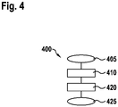
- FIG 4 shows a flowchart of a method 400 for operating a hybrid drive arrangement 200 with a transmission 100.
- the method starts with step 405.
- an operating specification signal BV is determined and in step 420 at least one of the shifting elements SE1...SE4 is actuated to adjust the functionality of the transmission 100 as a function of the operating specification signal BV.
- the operating specification signal BV is either a parameter for a physical variable in the transmission 100 such as, for example, a torque or a speed or a power to be transmitted, which is applied to a component of the transmission 100 or is to be transmitted.
- These components are in particular input shaft 10, output shaft 11 but also the parameters on the drive units 7, 8 or the switching elements SE1..SE4.
- the operating specification signal BV can also represent a specific operating mode such as one of the four gears G1...G4 or the two gears E1...E2, which are only operated with the second drive unit, or the special functions eCVT or stationary charging CH .
- the shifting elements SE1 to SE4 are actuated in accordance with the shifting matrix in order to shift the transmission 100 into the appropriate gear or operating mode.
Description
- Die Erfindung betrifft ein Getriebe für eine Hybridantriebsanordnung. Ferner betrifft die Erfindung eine Hybridantriebsanordnung mit einem Getriebe und ein Fahrzeug mit einer Hybridantriebsanordnung
- Getriebe für Hybridantriebsanordnungen sind aus dem Stand der Technik bekannt. Beispielsweise zeigt die
WO2010/009943 A1 ein Doppelkupplungsgetriebe, welches den Betrieb eines Hybridfahrzeugs verbrennungsmotorisch, elektromotorisch und mit beiden Antriebsaggregaten zusammen ermöglicht. Derartige Getriebe sind komplex, schwer und teuer. Es besteht Bedarf an Getriebetopologien mit reduzierter mechanischer Komplexität, verringertem Raumbedarf und verringertem Gewicht. - Aus der
DE 10 2015 209 294 A1 ist ein Getriebe für ein Hybridfahrzeug mit zwei Planetengetrieben bekannt, wobei ein Rotor einer elektrischen Maschine mit einem Planetenrad des ersten Planetengetriebes sowie mit einem Hohlrad des zweiten Planetengetriebes fest verbunden bzw. gekoppelt ist. - Aus der
DE 10 2008 044101 A1 ist ein Verfahren zur Vermeidung von Rasselgeräuschen im Hybridgetriebe eines Hybridfahrzeugs bekannt. Dabei ist eine Hybridbaugruppe vorgesehen sowie ein Basisgetriebe, welches mit der Hybridbaugruppe mittels einer Eingangswelle verbunden ist. Die Hybridbaugruppe weist eine mit einem Verbrennungsmotor koppelbare Antriebswelle auf. Die Hybridbaugruppe umfasst eine elektrische Maschine mit einem Rotor und einem Stator und ein als Planetengetriebe ausgeführtes Getriebe, wobei der Rotor mit dem Hohlrad des Planetengetriebes verbunden und das Sonnenrad des Planetengetriebes an ein Gehäuse gekoppelt ist. Die Eingangswelle ist mit dem Planetenrad des Planetengetriebes gekoppelt und sie ist über eine Trennkupplung mit der Antriebswelle koppelbar. Um Rasselgeräusche zu vermeiden ist dabei vorgesehen, dass die zumindest eine elektrische Maschine während des Betriebs des Verbrennungsmotors mit geringer Teillast betrieben wird, um im Getriebe die Anlage der Lastflanke und eine Zentrierung zu gewährleisten, wodurch Schwingungen der Verzahnungen des Getriebes und somit Rasselgeräusche vermieden werden. - Aus der
DE 10 2011 056 167 A1 ist ein Kraftübertragungssystem eines Hybridelektrofahrzeugs bekannt, wobei ein Getriebe mit zwei Planetengetrieben vorgesehen ist. Dabei ist ein Verbrennungsmotor ausschließlich mit dem Planetenrad des ersten Planetengetriebes fest verbunden bzw. mittels eines Schaltelements koppelbar. - Aus der
DE 10 2014 204 009 A1 ist ein mehrgängiges Planetengetriebesystem als Komponente des Antriebsstrangs eines Kraftfahrzeuges bekannt. - Der Begriff "gekoppelt" bzw. "angekoppelt" wird im Folgenden im Sinne einer festen Verbindung benutzt. Im Gegensatz dazu umfasst der Begriff "koppelbar" im Rahmen der vorliegenden Beschreibung sowohl feste als auch schaltbare Verbindungen. Ist konkret eine schaltbare Verbindung gemeint, wird in der Regel das entsprechende Schaltelement, insbesondere eine Bremse oder eine Kupplung, explizit angegeben. Ist hingegen konkret eine feste, starre oder drehfeste Verbindung gemeint, wird in der Regel der Begriff "gekoppelt" bzw. "angekoppelt" verwendet und auf die Verwendung des Begriffs "koppelbar" verzichtet. Die Verwendung des Begriffs "koppelbar" ohne Angabe eines konkreten Schaltelementes deutet somit auf den beabsichtigten Einschluss beider Fälle hin. Diese Unter-scheidung erfolgt allein zugunsten der besseren Verständlichkeit und insbesondere zur Verdeutlichung, wo das Vorsehen einer schaltbaren Verbindung anstelle einer in der Regel leichter realisierbaren festen Verbindung beziehungsweise Koppelung zwingend erforderlich ist. Die obige Definition des Begriffs "gekoppelt" bzw. "angekoppelt" ist daher keinesfalls so eng auszulegen, dass willkürlich zu Umgehungszwecken eingefügte Kupplungen aus seinem Wortsinn herausführten.
- Es wird ein Getriebe für eine Hybridantriebsanordnung bereitgestellt, welches mit zwei Antriebsaggregaten koppelbar ist, mit einer Eingangswelle und einer Ausgangswelle, mindestens einem ersten und einem zweiten Schaltelement und mindestens einem ersten und einem zweiten Planetengetriebe, wobei die Eingangswelle mittels dem ersten Schaltelement koppelbar ist mit dem Sonnenrad des ersten Planetengetriebes, welches mit dem Sonnenrad des zweiten Planetengetriebes gekoppelt ist, und die Eingangswelle mittels dem zweiten Schaltelement koppelbar ist mit dem Planetenträger des ersten Planetengetriebes, welcher mit dem Hohlrad des zweiten Planetengetriebes gekoppelt ist, und wobei die Ausgangswelle mit dem Planetenträger des zweiten Planetengetriebes gekoppelt ist.
- Es wird ein Getriebe für eine Hybridantriebsanordnung bereitgestellt. Für den Betrieb der Hybridantriebsanordnung sind zwei Antriebsaggregate an das Getriebe koppelbar. Das Getriebe umfasst eine Eingangswelle und eine Ausgangswelle, mindestens ein erstes und ein zweites Schaltelement und mindestens ein erstes und ein zweites Planetengetriebe. Die Eingangswelle ist fest mit dem ersten Schaltelement gekoppelt und somit drehfest verbunden. Im Rahmen der Beschreibung ist eine Koppelung somit eine Verbindung, welche starr, beispielsweise einstückig, beispielsweise mittels einer Welle, oder mit einer festen Übersetzung oder Getriebestufe ausgeführt ist. Weiter ist die Eingangswelle mittels Schließen des ersten Schaltelementes mit dem Sonnenrad des ersten Planetengetriebes koppelbar. Das Sonnenrad des ersten Planetengetriebes ist mit dem Sonnenrad des zweiten Planetengetriebes gekoppelt. Weiter ist die Eingangswelle mit dem zweiten Schaltelement gekoppelt und mittels Schließens des zweiten Schaltelementes mit dem Planetenträger des ersten Planetengetriebes koppelbar. Der Planetenträger des ersten Planetengetriebes ist mit dem Hohlrad des zweiten Planetengetriebes gekoppelt. Die Ausgangswelle ist mit dem Planetenträger des zweiten Planetengetriebes gekoppelt. Insbesondere ist die Ausgangswelle mit einem Abtrieb koppelbar. Der Abtrieb ist insbesondere eine Welle oder eine Achse, die die Bewegung der Ausgangswelle auf den mechanischen Antriebsstrang eines Fahrzeugs, beispielsweise auf ein Differenzial oder auf ein Antriebsrad überträgt. Vorteilhaft wird ein Getriebe bereitgestellt, welches die Drehzahl und das Drehmoment, welches an der Eingangswelle anliegt, bei geschlossenem erstem und zweitem Schaltelement entsprechend der Übersetzungsverhältnisse in dem Getriebe auf die Ausgangswelle überträgt.
- In einer anderen Ausgestaltung der Erfindung umfasst das Getriebe ein drittes Schaltelement, welches dazu eingerichtet ist, dass Hohlrad des ersten Planetengetriebes abzubremsen oder freizugeben.
- Für das Getriebe ist ein drittes Schaltelement vorgesehen, welches ein Freigeben oder Bremsen des Hohlrades des ersten Planetengetriebes ermöglicht, insbesondere ein Verbinden des Hohlrades oder ein Abstützen des Hohlrades an einem Fixpunkt oder an einem Gehäuse des Getriebes. Das Abbremsen des Hohlrades umfasst das Reduzieren der Drehzahl des Hohlrades, insbesondere bis zum Stillstand des Hohlrades. Das Freigeben des Hohlrades umfasst das Lösen der Bremse, so dass das Hohlrad entsprechend der auf das Hohlrad wirkenden Kräfte beschleunigt. Vorteilhaft lassen sich mit der bisher beschriebenen Topologie des Getriebes mit den ersten, zweiten und dritten Schaltelementen, neben den bereits erwähnten, weitere Betriebsmodi einstellen. So ergibt sich bei geschlossenem ersten und geöffneten zweiten Schaltelement sowie geschlossenem dritten Schaltelement ein weiteres Übersetzungsverhältnis zwischen Eingangswelle und Ausgangswelle. Bei geöffnetem erstem, geschlossenem zweitem und geschlossenem drittem Schaltelement ergibt sich eine dritte Übersetzung für den Betrieb des Getriebes. Bei geöffnetem erstem und zweitem Schaltelement ist die Eingangswelle von der Ausgangswelle abgekoppelt.
- Gemäß der Erfindung umfasst das Getriebe ein viertes Schaltelement, welches dazu eingerichtet ist, dass Hohlrad des zweiten Planetengetriebes abzubremsen oder freizugeben.
- Es ist ein viertes Schaltelement vorgesehen, welches das Hohlrad des zweiten Planetengetriebes freigeben oder abbremsen kann, insbesondere das Hohlrad mit einem Fixpunkt oder dem Gehäuse verbinden, koppeln oder das Hohlrad am Gehäuse abstützen. Das Abbremsen des Hohlrades umfasst das Reduzieren der Drehzahl des Hohlrades, insbesondere bis zum Stillstand des Hohlrades. Das Freigeben des Hohlrades umfasst das Lösen der Bremse, so dass das Hohlrad entsprechend der auf das Hohlrad wirkenden Kräfte beschleunigt. Vorteilhaft lassen sich mit der bisher beschriebenen Topologie des Getriebes mit dem ersten, zweiten, dritten und vierten Schaltelement, neben den bereits erwähnten, weitere Betriebsmodi einstellen. So ergibt sich vorteilhaft bei Schließen des ersten und des vierten Schaltelements und Öffnen des zweiten und des dritten Schaltelements eine vierte Übersetzung zwischen der Eingangs- und der Ausgangswelle. Bei geöffnetem erstem und zweitem Schaltelement ist die Eingangswelle von der Ausgangswelle abgekoppelt.
- In einer weiteren Ausgestaltung der Erfindung umfasst das erste und/oder das zweite Schaltelement eine Kupplung. Zur Verbindung der Eingangswelle mit den genannten Komponenten der Planetengetriebe sind das erste und/oder das zweite Schaltelement als Kupplung ausgeführt. Bei einer derartigen Kupplung kann es sich insbesondere um eine Trockenkupplung, Nasskupplung oder Klauenkupplung handeln. Vorteilhaft werden Möglichkeiten für eine steuerbare Verbindung der Eingangswelle mit den Komponenten der Planetengetriebe bereitgestellt.
- In einer anderen Ausgestaltung der Erfindung umfasst das dritte und/oder das vierte Schaltelement eine Bremse.
- Das dritte und/oder vierte Schaltelement sind als Bremse, insbesondere eine Trocken- oder Nassbremse oder als Klauenkupplung ausgeführt. Vorteilhaft wird eine Möglichkeit zur steuerbaren Freigabe und Abbremsung der Hohlräder des ersten oder des zweiten Planetengetriebes bereitgestellt.
- Gemäß der Erfindung ist ein erstes Antriebsaggregat, insbesondere eine Verbrennungskraftmaschine, mit der Eingangswelle koppelbar und ein zweites Antriebsaggregat, insbesondere eine elektrische Maschine, ist mit dem Sonnenrad des ersten Planetengetriebes und dem Sonnenrad des zweiten Planetengetriebes gekoppelt.
- An der Eingangswelle ist eingangsseitig das erste Antriebsaggregat ankoppelbar. Das zweite Antriebsaggregat ist mit dem Sonnenrad des ersten Planetengetriebes und dem Sonnenrad des zweiten Planetengetriebes gekoppelt.
- Vorteilhaft kann für einen generatorischen Betrieb des zweiten Antriebsaggregates, beispielsweise einer elektrischen Maschine, beispielsweise zum Laden einer Batterie, das erste Antriebsaggregat oder der Verbrennungsmotor mittels Schließen des ersten Schaltelements und Öffnen des zweiten, dritten und vierten Schaltelements mit der elektrischen Maschine verbunden werden. Da dabei beide Antriebsaggregate von der Ausgangswelle abgekoppelt sind und somit kein Drehmoment auf die Ausgangswelle übertragen wird, kann dieses Laden bei beispielsweise stillstehender Ausgangswelle, also beispielsweise während des Stillstands eines Fahrzeugs, erfolgen. Bei beispielsweise stillstehender Ausgangswelle wird eine direkte Übertragung der rotatorischen Energie des ersten Antriebsaggregates zum zweiten Antriebsaggregat oder umgekehrt ermöglicht.
- Ein leistungsverzweigter Betrieb des Getriebes (eCVT-Modus) wird durch Schließen des zweiten Schaltelements und Öffnen des ersten, dritten und vierten Schaltelements ermöglicht. Dabei wirken das erste Antriebsaggregat und die elektrische Maschine auf das zweite Planetengetriebe, welches mit der Ausgangswelle verbunden ist. Dabei lässt sich das Übersetzungsverhältnis zwischen Eingangswelle und Ausgangswelle über einen weiten Bereich mittels Vorgabe einer Drehzahl oder eines Drehmomentes des zweiten Antriebaggregates kontinuierlich variieren. Vorteilhaft wird ein leistungsverzweigter Betrieb, oder auch eCVT-Modus genannt, ermöglicht, bei dem sowohl die Vortriebsleistung an der Ausgangswelle, als auch die Ladeleistung für den generatorischen Betrieb der elektrischen Maschine unabhängig voneinander einstellbar sind. Vorteilhaft wird ein Laden im Stand oder im Kriechen (>0km/h bis ca. 10KM/h) und ein sanfter komfortabler Übergang vom Modus Standladen in den Modus Kriechladen und den Modus Fahren mit fester Übersetzung, bzw. im festem Gang ermöglicht.
- Bei geöffneten ersten und zweiten Schaltelement ist die Eingangswelle, und somit das erste Antriebsaggregat, von der Ausgangswelle abgekoppelt. Bei zusätzlich geschlossenen dritten Schaltelement ist das zweite Antriebsaggregat über eine erste Übersetzung mit der Abtriebswelle verbunden, so dass ein Antreiben der Ausgangswelle nur mittels des zweiten Antriebsaggregates erfolgen kann. Bei geöffnetem drittem und geschlossenem viertem Schaltelement ist das zweite Antriebsaggregat über eine zweite Übersetzung mit der Abtriebswelle gekoppelt. Dies ist eine zweite Übersetzung für einen alleinigen Antrieb mittels des zweiten Antriebsaggregates. Mittels, insbesondere dosiertem, Schließen des ersten Schaltelements kann aus dem Fahren mittels dem zweiten Antriebsaggregat das erste Antriebsaggregat angetrieben und beispielsweise gestartet werden, falls das erste Antriebsaggregat ein Verbrennungsmotor ist.
- Es besteht auch die Möglichkeit, dass das erste Antriebsaggregat beispielsweise als elektrische Maschine ausgestaltet ist und das zweite Antriebsaggregat beispielsweise als Verbrennungskraftmaschine ausgestaltet ist. In einer solchen Konfiguration können sich mittels des Getriebes andere Funktionalitäten und Betriebsmodi für das Zusammenwirken der Komponenten ergeben, die hier nicht weiter ausgeführt werden.
- In einer anderen Ausgestaltung der Erfindung erfolgt das Ändern der Übersetzungsverhältnisse des Getriebes zugkraftunterbrechungsfrei.
- Ein Ändern der Übersetzungsverhältnisse des Getriebes, insbesondere ein Schalten in einen anderen Gang oder in einen anderen Betriebsmodus des Getriebes erfolgt zugkraftunterbrechungsfrei, wenn insbesondere für den Wechsel aus einem Betriebsmodus des Getriebes in einen anderen eines der Schaltelement seinen Zustand beibehält, ein zweites der Schaltelemente aus einem geschlossenen Zustand in einen geöffneten Zustand überführt wird und ein drittes der Schaltelemente aus einem geöffneten in einen geschlossenen Zustand überführt wird. Vorteilhaft wird ein Getriebe bereitgestellt, bei dem das Wechseln der Gangstufen ohne eine Unterbrechung der Zugkraft ermöglicht wird.
- In einer anderen Ausgestaltung der Erfindung umfasst das Getriebe eine Ansteuerung zur Ansteuerung mindestens eines der Schaltelemente in Abhängigkeit eines vorgegebenen Betriebsvorgabesignals.
- Es ist eine Ansteuerung vorgesehen welche in Abhängigkeit eines vorgegebenen Betriebsvorgabesignals, beispielsweise ein angefordertes Drehmoment, eine vorgegebene Drehzahl, oder ein bestimmter Betriebspunkt der Antriebsaggregate, mindestens eines der Schaltelemente ansteuert. Die genannten Parameter des Betriebsvorgabesignals können auf die Ausgangswelle des Getriebes, auf die Eingangswelle oder auf die mit den Antriebsaggregaten zu verbindenden Wellen bezogen sein. Vorteilhaft wird eine Steuerung des Getriebes ermöglicht.
- Ferner betrifft die Erfindung eine Hybrid-Antriebsanordnung mit einem Getriebe, wobei die Hybridantriebsanordnung das zweite Antriebsaggregat (8) und einen Pulswechselrichter (60), eine elektrische Energiequelle (70) oder ein erstes Antriebsaggregat (7) umfasst.
- Es wird eine Hybridantriebsanordnung mit einem bisher beschriebenen Getriebe bereitgestellt. Die Hybridantriebsanordnung umfasst somit auch das zweite Antriebsaggregat. Insbesondere umfasst die Hybridantriebsanordnung einen Pulswechselrichter, eine elektrische Energiequelle und oder ein erstes Antriebsaggregat. Das zweite Antriebsaggregat ist mit den Sonnenrädern der Planetengetriebe gekoppelt oder verbunden. Der Pulswechselrichter ist insbesondere zur Versorgung des zweiten Antriebsaggregates, insbesondere einer elektrischen Maschine, vorgesehen. Hierzu wandelt er insbesondere die elektrische Energie einer elektrischen Energiequelle, beispielsweise einer Batterie und/ oder einer Brennstoffzelle um. Das erste Antriebsaggregat ist insbesondere mit der Eingangswelle gekoppelt oder verbunden. Vorteilhaft wird eine Hybridantriebsanordnung, welche für den Einsatz in einem Fahrzeug eingerichtet ist, bereitgestellt.
- Ferner umfasst die Erfindung ein Fahrzeug mit einer beschriebenen Hybridantriebsanordnung. Vorteilhaft wird ein Fahrzeug bereitgestellt, welches eine Hybridantriebsanordnung umfasst.
- Außerhalb des Umfangs der in den Ansprüchen definierten Erfindung wird ein Verfahren zum Betrieb einer Hybridantriebsanordnung mit einem Getriebe beschrieben. Das Verfahren umfasst folgende Schritte:
- Ermitteln eines Betriebsvorgabesignals;
- Ansteuern mindestens eines der Schaltelemente zur Einstellung der Funktionalität des Getriebes in Abhängigkeit des Betriebsvorgabesignals (BV).
- Es wird ein Verfahren zum Betrieb einer Hybridantriebsanordnung mit einem Getriebe bereitgestellt. Dabei wird ein Betriebsvorgabesignal ermittelt. Mindestens eines der Schaltelemente wird zur Einstellung der Funktionalität des Getriebes oder eines entsprechenden Betriebsmodus in Abhängigkeit des Betriebsvorgabesignals geschlossen oder geöffnet. Das Betriebsvorgabesignal wird in Abhängigkeit einer Betriebsstrategie, eines Fahrerwunsches oder Fahrpedals, eines Batteriemanagementsystems oder anderer beispielsweise in einem Fahrzeug verfügbaren Systemen vorgegeben. In Abhängigkeit dieses Betriebsvorgabesignals werden die Schaltelemente zur Einstellung der entsprechenden Funktionalität oder des Betriebsmodus des Getriebes angesteuert, insbesondere die Kupplungen oder Bremsen geschlossen oder geöffnet. Die Funktionalität des Getriebes oder der Betriebsmodus sind insbesondere die unterschiedlichen Übersetzungsverhältnisse der verschiedenen Gangstufen, oder die verschiedenen Modi oder Betriebsmodi, beispielsweise ein generatorischer Betrieb des zweiten Antriebsaggregates bei stillstehender Ausgangswelle oder der eCVT-Modus. Vorteilhaft wird ein Verfahren für den Betrieb der Hybridantriebsanordnung bereitgestellt.
- Es versteht sich, dass die Merkmale, Eigenschaften und Vorteile des Getriebes entsprechend auf die Hybridantriebsanordnung und auf das Fahrzeug zutreffen bzw. anwendbar sind. Weitere Merkmale und Vorteile von Ausführungsformen der Erfindung ergeben sich aus der nachfolgenden Beschreibung mit Bezug auf die beigefügten Zeichnungen.
- Im Folgenden soll die Erfindung anhand einiger Figuren näher erläutert werden, dazu zeigen:
-
Figur 1 : eine schematische Darstellung der Hybridantriebsstranganordnung mit einem Getriebe. -
Figur 2 : eine Schaltmatrix des Getriebes. -
Figur 3 : ein schematisch dargestelltes Fahrzeug mit einer Hybridantriebstranganordnung. -
Figur 4 : ein schematisch dargestelltes Verfahren zum Betrieb einer Hybridantriebstranganordnung. - Die
Figur 1 zeigt eine Hybridantriebstranganordnung 200 mit einem ersten Antriebsaggregat 7, insbesondere einem Verbrennungsmotor, und einem zweiten Antriebsaggregat 8, insbesondere einer elektrischen Maschine und einem Getriebe 100. Insbesondere umfasst die Hybridantriebstranganordnung einen Pulswechselrichter 60 zur Versorgung des zweiten Antriebsaggregates 8 mit elektrischer Energie. Weiter umfasst die Hybridantriebstranganordnung 200 insbesondere eine elektrische Energiequelle 70, welche mit dem Pulswechselrichter 60 verbunden ist. Das Getriebe 100 umfasst die Eingangswelle 10 und die Ausgangswelle 11. Weiter umfasst das Getriebe 100 ein erstes Planetengetriebe 5 und ein zweites Planetengetriebe 6. Weiter umfasst das Getriebe 100 ein erstes Schaltelement SE1 und ein zweites Schaltelement SE2. Das erste Schaltelement SE1, insbesondere eine Kupplung, ist dazu eingerichtet, die Eingangswelle 10 mit den Sonnenrädern des ersten und des zweiten Planetengetriebes 5, 6 zu verbinden oder zu trennen. Das zweite Schaltelement SE2, insbesondere eine Kupplung, ist dazu eingerichtet, die Eingangswelle mit dem Planetenträger des ersten Planetengetriebes 5 und dem Hohlrad des zweiten Planetengetriebes 6 zu verbinden oder zu trennen. Weiter kann das Getriebe 100 ein drittes Schaltelement SE3 und ein viertes Schaltelement SE4 umfassen. Das dritte Schaltelement SE3, insbesondere eine Bremse, ist dazu eingerichtet, das Hohlrad des ersten Planetengetriebes 5 freizugeben oder abzubremsen, insbesondere in dem die Bremse das Hohlrad mit einem Fixpunkt verbindet oder beispielsweise am Gehäuse (nicht dargestellt) des Getriebes 100 abstützt. Das Schaltelement SE4, insbesondere eine Bremse, ist dazu eingerichtet, das Hohlrad des zweiten Planetengetriebes 6 freizugeben oder abzubremsen, insbesondere in dem die Bremse das Hohlrad mit einem Fixpunkt verbindet oder beispielsweise am Gehäuse (nicht dargestellt) des Getriebes 100 abstützt. Das Getriebe ist weiter dazu eingerichtet, für den Betrieb mit einem ersten Antriebsaggregat 7 über die Eingangswelle 10 gekoppelt oder verbunden zu werden. In derFigur 1 ist dazu dargestellt, dass die Welle des Antriebsaggregates 7 über ein Stirnradsatz 16 mit der Eingangswelle 10 verbunden wird. Das zweite Antriebsaggregat 8, insbesondere eine elektrische Maschine, wird für den Betrieb des Getriebes 100 wie in derFigur 1 dargestellt mit den Sonnenrädern der Planetengetriebe 5 und 6 und dem Schaltelement 1 gekoppelt oder verbunden. Für eine Optimierung der Übersetzungsverhältnisse ist die Ausgangswelle 11 beispielsweise über einen Abtrieb 12, insbesondere einen Stirnradsatz, beispielsweise mit einem Differential 14 verbunden, über welches die Bewegungen auf die Räder 310 übertragen werden. Für die Ansteuerung der Schaltelemente ist eine Ansteuerung 50 vorgesehen, die das Verfahren zum Betrieb der Hybridantriebsanordnung mit dem Getriebe ausführt. Mittels der Pfeile an der Ansteuerung 50 sind die Steuerleitungen zwischen der Ansteuerung 50 und den Schaltelementen SE1..SE4 angedeutet. Diese Steuerleitungen sind für eine verbesserte Darstellung nicht vollständig eingezeichnet. Die Kommunikation zwischen den Schaltelementen und der Vorrichtung kann jedoch auch mittels eines BUS-Systems oder kabellos erfolgen. -
Figur 2 zeigt eine Schaltmatrix des Getriebes. In den Spalten sind die einzelnen Schaltelemente SE1..SE4 angegeben und in der letzten Spalte beispielhaft ein sich zwischen der Eingangswelle und der Ausgangswelle ergebendes ungefähres Übersetzungsverhältnis. In den Zeilen sind die unterschiedlichen Gangstufen, Gänge oder Betriebsmodi des Getriebes angegeben. Mittels Kreuzen ist in der Schaltmatrix dargestellt, welches der Schaltelemente aktiviert sein muss, damit sich der entsprechende Gang oder Betriebsmodus einstellt. Mit Aktivierung der Schaltelemente ist hierbei insbesondere gemeint, dass eine Kupplung geschlossen wird oder eine Bremse betätigt wird, sodass über die Kupplung eine Kraft von einer Welle auf eine weitere Welle übertragen werden kann und mittels der Bremse eine Kraft auf einen Fixpunkt, insbesondere das Getriebegehäuse, übertragen werden kann. Aus der Schaltmatrix ist ersichtlich, dass sich je nach Kombination der vier Schaltelemente vier Gänge G1.....G4 einstellen lassen, wobei der erste Gang G1 das höchste Übersetzungsverhältnis und der vierte Gang G4 das niedrigste Übersetzungsverhältnis aufweist. Bei diesen Gängen liegt zwischen Eingangs- und Ausgangswelle in festes Drehzahlverhältnis entsprechend der Übersetzung an und ein erstes und zweites Antriebsaggregat treiben entweder jeweils einzeln oder zusammen die Ausgangswelle 11 an. Insbesondere sind dies verbrennungsmotorische oder hybridische Gänge, beispielsweise wenn das Antriebsaggregat ein Verbrennungsmotor ist und das zweite Antriebsaggregat eine elektrische Maschine ist. Diese Gänge ermöglichen auch eine Lastpunktanhebung des Verbrennungsmotors, so dass die elektrische Maschine generatorisch betrieben werden kann und ein Laden einer Batterie während des Betriebs, insbesondere Fahrbetrieb eines Fahrzeugs, erfolgen kann. In den folgenden Zeilen der Matrix schließen sich die Gänge E1 und E2 oder Betriebsmodi an, in denen nur das zweite Antriebsaggregat mit der Ausgangswelle 11 verbunden ist. Hierzu müssen insbesondere das erste und das zweite Schaltelement geöffnet sein, damit keine Verbindung zum ersten Antriebsaggregat besteht. Dies sind insbesondere elektromotorische Gänge, beispielsweise wenn das zweite Antriebsaggregat eine elektrische Maschine ist. Vorteilhaft kann in diesen Gängen ein Fahrzeug lokal emissionsfrei betrieben werden. Je nachdem, ob das zweite Antriebsaggregat über das zweite Planetengetriebe 6 und das vierte Schaltelement SE4 mit der Ausgangswelle 11 gekoppelt wird, ergibt sich eine hohe Übersetzung oder bei Verbindung des zweiten Antriebsaggregates über das erste Planetengetriebe 5 und das Schaltelement 3 ergibt sich eine niedrigere Übersetzung, wie in der letzten Spalte der Schaltmatrix dargestellt. - Durch Öffnen des dritten und vierten Schaltelementes SE3, SE4 und des ersten Schaltelementes SE1 und Schließen des zweiten Schaltelementes SE2 ergibt sich ein leistungsverzweigter Betrieb, der eCVT-Modus, welcher eine voneinander unabhängige Vortriebsleistung an der Ausgangswelle 11 und Ladeleistung des zweiten Antriebsaggregates 8 ermöglicht. Insbesondere eignet sich dieser Betriebsmodus zum hybridischen Anfahren bei niedrigem Batterieladezustand, da ein stufenloses Verändern der Übersetzungsverhältnisse und damit insbesondere stufenloses Beschleunigen bei gleichzeitigem generatorischen Betrieb des zweiten Antriebsaggregates 8 möglich ist.
- Ein weiterer Modus CH, oder auch Standladen genannt, ergibt sich, wenn nur das erste Schaltelement SE1 geschlossen ist und alle weiteren drei Schaltelemente SE2..SE4 geöffnet sind. Die Antriebsaggregate 7 und 8 werden dabei miteinander gekoppelt, wobei keine Verbindung zur Ausgangswelle 11 besteht. In diesem Betriebsmodus kann während des Stillstands der Ausgangswelle, insbesondere eines Fahrzeugs, mittels des ersten Antriebsaggregates 7 das zweite 8 angetrieben werden, beispielsweise generatorisch zum Laden einer elektrischen Energiequelle 70, beispielsweise eine Batterie, verwendet werden. Alternativ kann mittels des zweiten Antriebsaggregates 8 auch das erste 7 angetrieben werden und beispielsweise ein Verbrennungsmotorstart oder eine Diagnose des Verbrennungsmotors durchgeführt werden, falls das erste Antriebsaggregat 7 ein Verbrennungsmotor ist und das zweite Antriebsaggregat 8 eine elektrische Maschine ist.
-
Figur 3 zeigt ein Fahrzeug 300 mit Rädern 310, wobei das Fahrzeug eine Hybridantriebsanordnung 200, wie oben beschrieben, umfasst. -
Figur 4 zeigt ein Ablaufdiagramm eines Verfahrens 400 zum Betrieb einer Hybridantriebsanordnung 200 mit einem Getriebe 100. Mit Schritt 405 startet das Verfahren. In Schritt 410 wird ein Betriebsvorgabesignal BV ermittelt und in Schritt 420 mindestens eines der Schaltelemente SE1....SE4 zur Einstellung der Funktionalität des Getriebes 100 in Abhängigkeit des Betriebsvorgabesignals BV angesteuert. Mit Schritt 425 endet das Verfahren. Das Betriebsvorgabesignal BV ist hierbei entweder ein Parameter für eine physikalische Größe im Getriebe 100 wie z.B. ein Drehmoment oder eine Drehzahl oder eine zu übertragende Leistung, welche an einer Komponente des Getriebes 100 anliegen oder übertragen werden soll. Diese Komponenten sind insbesondere Eingangswelle 10, Ausgangswelle 11 aber auch die Parameter an den Antriebsaggregaten 7, 8 oder den Schaltelementen SE1..SE4. Darüber hinaus kann das Betriebsvorgabesignal BV auch einen bestimmten Betriebsmodus wie einen der vier Gänge G1.....G4 oder der zwei Gänge E1..E2, welche nur mit dem zweiten Antriebsaggregat betrieben werden, oder auch die besonderen Funktionen eCVT oder Standladen CH darstellen. In Abhängigkeit dieses Betriebsvorgabesignals BV werden die Schaltelemente SE1 bis SE4 entsprechend der Schaltmatrix angesteuert, um das Getriebe 100 in den entsprechenden Gang oder Betriebsmodus zu schalten. Für eine zugkraftunterbrechungsfreie Umschaltung zwischen den einzelnen Gängen oder Betriebsmodi ist es notwendig, dass eines der Schaltelemente SE1..SE4 seinen Zustand vor und nach der Schaltung beibehält, wobei ein weiteres Schaltelement während des Schaltens aus dem geöffneten in den geschlossenen Zustand übergeht, während ein anderes aus dem geschlossenen in den geöffneten Zustand übergeht.
Claims (8)
- Getriebe (100) für eine Hybridantriebsanordnung,welches mit zwei Antriebsaggregaten (7, 8) koppelbar ist,miteiner Eingangswelle (10) und einer Ausgangswelle (11),mindestens einem ersten und einem zweiten Schaltelement (SE1, SE2),einem vierten Schaltelement (SE4),mindestens einem ersten und einem zweiten Planetengetriebe (5,6)wobeiein erstes Antriebsaggregat (7), insbesondere eine Verbrennungskraftmaschine,mit der Eingangswelle (10) koppelbar ist,wobei die Eingangswelle (10) mittels dem ersten Schaltelement (SE1) koppelbar ist mit dem Sonnenrad des ersten Planetengetriebes (5), welches mit dem Sonnenrad des zweiten Planetengetriebes (6) gekoppelt ist,wobei die Eingangswelle (10) mittels dem zweiten Schaltelement (SE2) koppelbar ist mit dem Planetenträger des ersten Planetengetriebes (5), welcher mit dem Hohlrad des zweiten Planetengetriebes (6) gekoppelt ist,wobei das vierte Schaltelement (SE4) dazu eingerichtet ist, das Hohlrad des zweiten Planetengetriebes (6) abzubremsen oder freizugeben,und wobei die Ausgangswelle (11) mit dem Planetenträger des zweiten Planetengetriebes (6) gekoppelt ist,dadurch gekennzeichnet, dass ein zweites Antriebsaggregat (8), insbesondere eine elektrische Maschine, mit dem Sonnenrad des ersten Planetengetriebes (5) und dem Sonnenrad des zweiten Planetengetriebes (6) gekoppelt
- Getriebe nach Anspruch 1,
mit einem dritten Schaltelement (SE3), welches dazu eingerichtet ist, das Hohlrad des ersten Planetengetriebes (5) abzubremsen oder freizugeben. - Getriebe nach einem der vorhergehenden Ansprüche,
wobei das erste und/ oder das zweite Schaltelement (SE1, SE2) eine Kupplung umfasst. - Getriebe nach einem der vorhergehenden Ansprüche,sowie nach Anspruch 2, soweit das dritte Schaltelement betroffen ist,wobei das dritte und/ oder das vierte Schaltelement (SE3, SE4) eine Bremse umfasst.
- Getriebe nach einem der vorhergehenden Ansprüche,
wobei ein Ändern der Übersetzungsverhältnisse des Getriebes (100) zugkraftunterbrechungsfrei erfolgt. - Getriebe nach einem der vorhergehenden Ansprüche,
mit einer Ansteuerung (50) zur Ansteuerung mindestens eines der Schaltelemente (SE1..SE4) in Abhängigkeit eines vorgegebenen Betriebsvorgabesignals (BV). - Hybridantriebsanordnung (200) mit einem Getriebe (100) nach einem der Ansprüche 1 bis 8, wobei die Hybridantriebsanordnung das zweite Antriebsaggregat (8) und
einen Pulswechselrichter (60), eine elektrische Energiequelle oder ein erstes Antriebsaggregat (7) umfasst. - Fahrzeug (300) mit einer Hybridantriebsanordnung (200) nach Anspruch 7.
Applications Claiming Priority (2)
| Application Number | Priority Date | Filing Date | Title |
|---|---|---|---|
| DE102017213385.6A DE102017213385A1 (de) | 2017-08-02 | 2017-08-02 | Getriebe für eine Hybridantriebsanordnung |
| PCT/EP2018/070689 WO2019025420A1 (de) | 2017-08-02 | 2018-07-31 | Getriebe für eine hybridantriebsanordnung, hybridantriebsanordnung, fahrzeug, verfahren zum betrieb der hybridantriebsanordnung, computerprogramm und speichermedium |
Publications (2)
| Publication Number | Publication Date |
|---|---|
| EP3661791A1 EP3661791A1 (de) | 2020-06-10 |
| EP3661791B1 true EP3661791B1 (de) | 2022-06-22 |
Family
ID=63108546
Family Applications (1)
| Application Number | Title | Priority Date | Filing Date |
|---|---|---|---|
| EP18750142.4A Active EP3661791B1 (de) | 2017-08-02 | 2018-07-31 | Getriebe für eine hybridantriebsanordnung, hybridantriebsanordnung und fahrzeug |
Country Status (5)
| Country | Link |
|---|---|
| US (1) | US11084368B2 (de) |
| EP (1) | EP3661791B1 (de) |
| CN (1) | CN111148644B (de) |
| DE (1) | DE102017213385A1 (de) |
| WO (1) | WO2019025420A1 (de) |
Families Citing this family (9)
| Publication number | Priority date | Publication date | Assignee | Title |
|---|---|---|---|---|
| DE102019206545B4 (de) | 2019-05-07 | 2021-03-25 | Getrag Ford Transmissions Gmbh | Antriebsstrang |
| CN110271404A (zh) * | 2019-06-12 | 2019-09-24 | 浙江吉利控股集团有限公司 | 一种单电机混合动力机构 |
| CN110259893A (zh) * | 2019-06-12 | 2019-09-20 | 浙江吉利控股集团有限公司 | 一种自动变速器传动系统及汽车 |
| CN110271406A (zh) * | 2019-06-12 | 2019-09-24 | 浙江吉利控股集团有限公司 | 一种混合动力机构及汽车 |
| CN110271405A (zh) * | 2019-06-12 | 2019-09-24 | 浙江吉利控股集团有限公司 | 一种动力传动系统及汽车 |
| CN110271403A (zh) * | 2019-06-12 | 2019-09-24 | 浙江吉利控股集团有限公司 | 一种双电机混动系统变速装置 |
| CN110281759A (zh) * | 2019-06-12 | 2019-09-27 | 浙江吉利控股集团有限公司 | 一种汽车行星齿轮变速装置 |
| DE102019217152A1 (de) * | 2019-11-06 | 2021-05-06 | Magna Pt B.V. & Co. Kg | Antriebsstrang mit einem Getriebe für ein Hybridfahrzeug, sowie Verfahren zum Schalten des Getriebes |
| KR20230100291A (ko) * | 2021-12-28 | 2023-07-05 | 현대자동차주식회사 | 차량의 하이브리드 파워트레인 |
Family Cites Families (15)
| Publication number | Priority date | Publication date | Assignee | Title |
|---|---|---|---|---|
| US6589128B2 (en) * | 2001-11-02 | 2003-07-08 | New Ventures Gear, Inc. | On-demand two-speed transfer case for four-wheel drive hybrid vehicle |
| US7232393B2 (en) * | 2005-04-01 | 2007-06-19 | Gm Global Technology Operations, Inc. | Electrically variable transmission having two planetary gear sets with two fixed interconnections |
| US7288041B2 (en) * | 2005-09-29 | 2007-10-30 | Gm Global Technology Operations, Inc. | Multi-mode electrically variable transmissions having two planetary gear sets with two fixed interconnections and clutched input |
| DE102008040692A1 (de) | 2008-07-24 | 2010-01-28 | Robert Bosch Gmbh | Verfahren und Vorrichtung zum Anfahren eines Hybridfahrzeuges |
| DE102008044101A1 (de) * | 2008-11-27 | 2010-06-02 | Zf Friedrichshafen Ag | Verfahren zur Vermeidung von Rasselgeräuschen im Hybridgetriebe eines Hybridfahrzeugs |
| KR101163822B1 (ko) * | 2009-03-09 | 2012-07-09 | 현대자동차주식회사 | 하이브리드 차량의 파워트레인 |
| DE102011005531B4 (de) * | 2011-03-15 | 2023-12-14 | Zf Friedrichshafen Ag | Hybridantrieb eines Kraftfahrzeuges |
| KR101283046B1 (ko) * | 2011-06-20 | 2013-07-05 | 기아자동차주식회사 | 하이브리드 차량의 동력전달장치 |
| DE102011109352A1 (de) * | 2011-08-03 | 2013-02-07 | Volkswagen Aktiengesellschaft | Hybridantriebsordnung für ein Kraftfahrzeug |
| DE102011087995A1 (de) * | 2011-12-08 | 2013-06-13 | Zf Friedrichshafen Ag | Getriebe und Antriebstrang mit einem Getriebe |
| CN104364148B (zh) * | 2012-05-31 | 2017-05-03 | 罗伯特·博世有限公司 | 行星齿轮传动装置和电动车辆 |
| DE102014204009A1 (de) * | 2014-03-05 | 2015-09-10 | Schaeffler Technologies AG & Co. KG | Mehrgängiges Planetengetriebesystem als Komponente des Antriebsstrangs eines Kraftfahrzeuges |
| DE102015209294A1 (de) * | 2015-05-21 | 2016-11-24 | Zf Friedrichshafen Ag | Getriebe für ein Hybridfahrzeug, und Antriebsstrang für ein Hybridfahrzeug |
| EP3095631A1 (de) * | 2015-05-21 | 2016-11-23 | ZF Friedrichshafen AG | Getriebe für ein hybridfahrzeug, und antriebsstrang für ein hybridfahrzeug |
| KR102575184B1 (ko) * | 2018-08-22 | 2023-09-05 | 현대자동차 주식회사 | 차량용 변속장치 |
-
2017
- 2017-08-02 DE DE102017213385.6A patent/DE102017213385A1/de not_active Withdrawn
-
2018
- 2018-07-31 CN CN201880064227.9A patent/CN111148644B/zh active Active
- 2018-07-31 WO PCT/EP2018/070689 patent/WO2019025420A1/de unknown
- 2018-07-31 EP EP18750142.4A patent/EP3661791B1/de active Active
- 2018-07-31 US US16/636,059 patent/US11084368B2/en active Active
Also Published As
| Publication number | Publication date |
|---|---|
| CN111148644B (zh) | 2023-07-07 |
| DE102017213385A1 (de) | 2019-02-07 |
| US20210162851A1 (en) | 2021-06-03 |
| CN111148644A (zh) | 2020-05-12 |
| WO2019025420A1 (de) | 2019-02-07 |
| US11084368B2 (en) | 2021-08-10 |
| EP3661791A1 (de) | 2020-06-10 |
Similar Documents
| Publication | Publication Date | Title |
|---|---|---|
| EP3661791B1 (de) | Getriebe für eine hybridantriebsanordnung, hybridantriebsanordnung und fahrzeug | |
| EP3661787B1 (de) | Getriebe für eine hybridantriebsanordnung, hybridantriebsanordnung und fahrzeug | |
| EP3661782B1 (de) | Hybridantriebsanordnung | |
| EP3661789A1 (de) | Getriebe für eine hybridantriebsanordnung, hybridantriebsanordnung, fahrzeug, verfahren zum betrieb der hybridantriebsanordnung, computerprogramm und speichermedium | |
| EP3661790B1 (de) | Getriebe für eine hybridantriebsanordnung, hybridantriebsanordnung und fahrzeug | |
| EP3661786B1 (de) | Getriebe für eine hybridantriebsanordnung, hybridantriebsanordnung und fahrzeug | |
| EP3661785B1 (de) | Getriebe für eine hybridantriebsanordnung, hybridantriebsanordnung und fahrzeug | |
| EP3661788B1 (de) | Getriebe für eine hybridantriebsanordnung, hybridantriebsanordnung und fahrzeug | |
| EP3661784B1 (de) | Getriebe für eine hybridantriebsanordnung, hybridantriebsanordnung und fahrzeug | |
| WO2020249336A1 (de) | Getriebe für eine hybridantriebsanordnung, hybridantriebsanordning, fahrzeug, und verfahren zum betreiben der hybridantriebsanordnung | |
| WO2020249307A1 (de) | Getriebe für eine hybridantriebsanordnung, hybridantriebsanordnung, fahrzeug, und verfahren zum betreiben der hybridantriebsanordnung | |
| WO2020249308A1 (de) | Getriebe für eine hybridantriebsanordnung, hybridantriebsanordning, fahrzeug, und verfahren zum betreiben der hybridantriebsanordnung | |
| WO2020249338A1 (de) | Getriebe für eine hybridantriebsanordnung, hybridantriebsanordning, fahrzeug, und verfahren zum betreiben der hybridantriebsanordnung | |
| WO2020249337A1 (de) | Getriebe für eine hybridantriebsanordnung, hybridantriebsanordning, fahrzeug, und verfahren zum betreiben der hybridantriebsanordnung | |
| WO2020249309A1 (de) | Getriebe für eine hybridantriebsanordnung, hybridantriebsanordnung, fahrzeug, und verfahren zum betreiben der hybridantriebsanordnung | |
| DE102019208598A1 (de) | Getriebe für eine Hybridantriebsanordnung | |
| DE102017213340A1 (de) | Getriebe für eine Hybridantriebsanordnung | |
| DE102019208594A1 (de) | Getriebe für eine Hybridantriebsanordnung |
Legal Events
| Date | Code | Title | Description |
|---|---|---|---|
| STAA | Information on the status of an ep patent application or granted ep patent |
Free format text: STATUS: UNKNOWN |
|
| STAA | Information on the status of an ep patent application or granted ep patent |
Free format text: STATUS: THE INTERNATIONAL PUBLICATION HAS BEEN MADE |
|
| PUAI | Public reference made under article 153(3) epc to a published international application that has entered the european phase |
Free format text: ORIGINAL CODE: 0009012 |
|
| STAA | Information on the status of an ep patent application or granted ep patent |
Free format text: STATUS: REQUEST FOR EXAMINATION WAS MADE |
|
| 17P | Request for examination filed |
Effective date: 20200302 |
|
| AK | Designated contracting states |
Kind code of ref document: A1 Designated state(s): AL AT BE BG CH CY CZ DE DK EE ES FI FR GB GR HR HU IE IS IT LI LT LU LV MC MK MT NL NO PL PT RO RS SE SI SK SM TR |
|
| AX | Request for extension of the european patent |
Extension state: BA ME |
|
| DAV | Request for validation of the european patent (deleted) | ||
| DAX | Request for extension of the european patent (deleted) | ||
| GRAP | Despatch of communication of intention to grant a patent |
Free format text: ORIGINAL CODE: EPIDOSNIGR1 |
|
| STAA | Information on the status of an ep patent application or granted ep patent |
Free format text: STATUS: GRANT OF PATENT IS INTENDED |
|
| INTG | Intention to grant announced |
Effective date: 20220317 |
|
| GRAS | Grant fee paid |
Free format text: ORIGINAL CODE: EPIDOSNIGR3 |
|
| GRAA | (expected) grant |
Free format text: ORIGINAL CODE: 0009210 |
|
| STAA | Information on the status of an ep patent application or granted ep patent |
Free format text: STATUS: THE PATENT HAS BEEN GRANTED |
|
| AK | Designated contracting states |
Kind code of ref document: B1 Designated state(s): AL AT BE BG CH CY CZ DE DK EE ES FI FR GB GR HR HU IE IS IT LI LT LU LV MC MK MT NL NO PL PT RO RS SE SI SK SM TR |
|
| REG | Reference to a national code |
Ref country code: GB Ref legal event code: FG4D Free format text: NOT ENGLISH |
|
| REG | Reference to a national code |
Ref country code: CH Ref legal event code: EP |
|
| REG | Reference to a national code |
Ref country code: DE Ref legal event code: R096 Ref document number: 502018009990 Country of ref document: DE |
|
| REG | Reference to a national code |
Ref country code: AT Ref legal event code: REF Ref document number: 1499567 Country of ref document: AT Kind code of ref document: T Effective date: 20220715 |
|
| REG | Reference to a national code |
Ref country code: IE Ref legal event code: FG4D Free format text: LANGUAGE OF EP DOCUMENT: GERMAN |
|
| REG | Reference to a national code |
Ref country code: LT Ref legal event code: MG9D |
|
| REG | Reference to a national code |
Ref country code: NL Ref legal event code: MP Effective date: 20220622 |
|
| PG25 | Lapsed in a contracting state [announced via postgrant information from national office to epo] |
Ref country code: SE Free format text: LAPSE BECAUSE OF FAILURE TO SUBMIT A TRANSLATION OF THE DESCRIPTION OR TO PAY THE FEE WITHIN THE PRESCRIBED TIME-LIMIT Effective date: 20220622 Ref country code: NO Free format text: LAPSE BECAUSE OF FAILURE TO SUBMIT A TRANSLATION OF THE DESCRIPTION OR TO PAY THE FEE WITHIN THE PRESCRIBED TIME-LIMIT Effective date: 20220922 Ref country code: LT Free format text: LAPSE BECAUSE OF FAILURE TO SUBMIT A TRANSLATION OF THE DESCRIPTION OR TO PAY THE FEE WITHIN THE PRESCRIBED TIME-LIMIT Effective date: 20220622 Ref country code: HR Free format text: LAPSE BECAUSE OF FAILURE TO SUBMIT A TRANSLATION OF THE DESCRIPTION OR TO PAY THE FEE WITHIN THE PRESCRIBED TIME-LIMIT Effective date: 20220622 Ref country code: GR Free format text: LAPSE BECAUSE OF FAILURE TO SUBMIT A TRANSLATION OF THE DESCRIPTION OR TO PAY THE FEE WITHIN THE PRESCRIBED TIME-LIMIT Effective date: 20220923 Ref country code: FI Free format text: LAPSE BECAUSE OF FAILURE TO SUBMIT A TRANSLATION OF THE DESCRIPTION OR TO PAY THE FEE WITHIN THE PRESCRIBED TIME-LIMIT Effective date: 20220622 Ref country code: BG Free format text: LAPSE BECAUSE OF FAILURE TO SUBMIT A TRANSLATION OF THE DESCRIPTION OR TO PAY THE FEE WITHIN THE PRESCRIBED TIME-LIMIT Effective date: 20220922 |
|
| PG25 | Lapsed in a contracting state [announced via postgrant information from national office to epo] |
Ref country code: RS Free format text: LAPSE BECAUSE OF FAILURE TO SUBMIT A TRANSLATION OF THE DESCRIPTION OR TO PAY THE FEE WITHIN THE PRESCRIBED TIME-LIMIT Effective date: 20220622 Ref country code: LV Free format text: LAPSE BECAUSE OF FAILURE TO SUBMIT A TRANSLATION OF THE DESCRIPTION OR TO PAY THE FEE WITHIN THE PRESCRIBED TIME-LIMIT Effective date: 20220622 |
|
| PG25 | Lapsed in a contracting state [announced via postgrant information from national office to epo] |
Ref country code: NL Free format text: LAPSE BECAUSE OF FAILURE TO SUBMIT A TRANSLATION OF THE DESCRIPTION OR TO PAY THE FEE WITHIN THE PRESCRIBED TIME-LIMIT Effective date: 20220622 |
|
| PG25 | Lapsed in a contracting state [announced via postgrant information from national office to epo] |
Ref country code: SM Free format text: LAPSE BECAUSE OF FAILURE TO SUBMIT A TRANSLATION OF THE DESCRIPTION OR TO PAY THE FEE WITHIN THE PRESCRIBED TIME-LIMIT Effective date: 20220622 Ref country code: SK Free format text: LAPSE BECAUSE OF FAILURE TO SUBMIT A TRANSLATION OF THE DESCRIPTION OR TO PAY THE FEE WITHIN THE PRESCRIBED TIME-LIMIT Effective date: 20220622 Ref country code: RO Free format text: LAPSE BECAUSE OF FAILURE TO SUBMIT A TRANSLATION OF THE DESCRIPTION OR TO PAY THE FEE WITHIN THE PRESCRIBED TIME-LIMIT Effective date: 20220622 Ref country code: PT Free format text: LAPSE BECAUSE OF FAILURE TO SUBMIT A TRANSLATION OF THE DESCRIPTION OR TO PAY THE FEE WITHIN THE PRESCRIBED TIME-LIMIT Effective date: 20221024 Ref country code: ES Free format text: LAPSE BECAUSE OF FAILURE TO SUBMIT A TRANSLATION OF THE DESCRIPTION OR TO PAY THE FEE WITHIN THE PRESCRIBED TIME-LIMIT Effective date: 20220622 Ref country code: EE Free format text: LAPSE BECAUSE OF FAILURE TO SUBMIT A TRANSLATION OF THE DESCRIPTION OR TO PAY THE FEE WITHIN THE PRESCRIBED TIME-LIMIT Effective date: 20220622 Ref country code: CZ Free format text: LAPSE BECAUSE OF FAILURE TO SUBMIT A TRANSLATION OF THE DESCRIPTION OR TO PAY THE FEE WITHIN THE PRESCRIBED TIME-LIMIT Effective date: 20220622 |
|
| PG25 | Lapsed in a contracting state [announced via postgrant information from national office to epo] |
Ref country code: PL Free format text: LAPSE BECAUSE OF FAILURE TO SUBMIT A TRANSLATION OF THE DESCRIPTION OR TO PAY THE FEE WITHIN THE PRESCRIBED TIME-LIMIT Effective date: 20220622 Ref country code: IS Free format text: LAPSE BECAUSE OF FAILURE TO SUBMIT A TRANSLATION OF THE DESCRIPTION OR TO PAY THE FEE WITHIN THE PRESCRIBED TIME-LIMIT Effective date: 20221022 |
|
| REG | Reference to a national code |
Ref country code: CH Ref legal event code: PL |
|
| REG | Reference to a national code |
Ref country code: DE Ref legal event code: R097 Ref document number: 502018009990 Country of ref document: DE |
|
| REG | Reference to a national code |
Ref country code: BE Ref legal event code: MM Effective date: 20220731 |
|
| PG25 | Lapsed in a contracting state [announced via postgrant information from national office to epo] |
Ref country code: MC Free format text: LAPSE BECAUSE OF FAILURE TO SUBMIT A TRANSLATION OF THE DESCRIPTION OR TO PAY THE FEE WITHIN THE PRESCRIBED TIME-LIMIT Effective date: 20220622 Ref country code: AL Free format text: LAPSE BECAUSE OF FAILURE TO SUBMIT A TRANSLATION OF THE DESCRIPTION OR TO PAY THE FEE WITHIN THE PRESCRIBED TIME-LIMIT Effective date: 20220622 |
|
| PG25 | Lapsed in a contracting state [announced via postgrant information from national office to epo] |
Ref country code: LU Free format text: LAPSE BECAUSE OF NON-PAYMENT OF DUE FEES Effective date: 20220731 Ref country code: LI Free format text: LAPSE BECAUSE OF NON-PAYMENT OF DUE FEES Effective date: 20220731 Ref country code: DK Free format text: LAPSE BECAUSE OF FAILURE TO SUBMIT A TRANSLATION OF THE DESCRIPTION OR TO PAY THE FEE WITHIN THE PRESCRIBED TIME-LIMIT Effective date: 20220622 Ref country code: CH Free format text: LAPSE BECAUSE OF NON-PAYMENT OF DUE FEES Effective date: 20220731 |
|
| PLBE | No opposition filed within time limit |
Free format text: ORIGINAL CODE: 0009261 |
|
| STAA | Information on the status of an ep patent application or granted ep patent |
Free format text: STATUS: NO OPPOSITION FILED WITHIN TIME LIMIT |
|
| GBPC | Gb: european patent ceased through non-payment of renewal fee |
Effective date: 20220922 |
|
| 26N | No opposition filed |
Effective date: 20230323 |
|
| PG25 | Lapsed in a contracting state [announced via postgrant information from national office to epo] |
Ref country code: BE Free format text: LAPSE BECAUSE OF NON-PAYMENT OF DUE FEES Effective date: 20220731 |
|
| PG25 | Lapsed in a contracting state [announced via postgrant information from national office to epo] |
Ref country code: IE Free format text: LAPSE BECAUSE OF NON-PAYMENT OF DUE FEES Effective date: 20220731 Ref country code: FR Free format text: LAPSE BECAUSE OF NON-PAYMENT OF DUE FEES Effective date: 20220822 |
|
| PG25 | Lapsed in a contracting state [announced via postgrant information from national office to epo] |
Ref country code: SI Free format text: LAPSE BECAUSE OF FAILURE TO SUBMIT A TRANSLATION OF THE DESCRIPTION OR TO PAY THE FEE WITHIN THE PRESCRIBED TIME-LIMIT Effective date: 20220622 |
|
| PG25 | Lapsed in a contracting state [announced via postgrant information from national office to epo] |
Ref country code: GB Free format text: LAPSE BECAUSE OF NON-PAYMENT OF DUE FEES Effective date: 20220922 |
|
| PGFP | Annual fee paid to national office [announced via postgrant information from national office to epo] |
Ref country code: DE Payment date: 20230922 Year of fee payment: 6 |
|
| PG25 | Lapsed in a contracting state [announced via postgrant information from national office to epo] |
Ref country code: IT Free format text: LAPSE BECAUSE OF FAILURE TO SUBMIT A TRANSLATION OF THE DESCRIPTION OR TO PAY THE FEE WITHIN THE PRESCRIBED TIME-LIMIT Effective date: 20220622 |