EP3661720B1 - Method for the variothermal temperature control of injection moulds - Google Patents
Method for the variothermal temperature control of injection moulds Download PDFInfo
- Publication number
- EP3661720B1 EP3661720B1 EP18739510.8A EP18739510A EP3661720B1 EP 3661720 B1 EP3661720 B1 EP 3661720B1 EP 18739510 A EP18739510 A EP 18739510A EP 3661720 B1 EP3661720 B1 EP 3661720B1
- Authority
- EP
- European Patent Office
- Prior art keywords
- temperature
- heating
- cooling
- time
- temperature control
- Prior art date
- Legal status (The legal status is an assumption and is not a legal conclusion. Google has not performed a legal analysis and makes no representation as to the accuracy of the status listed.)
- Active
Links
- 238000000034 method Methods 0.000 title claims description 113
- 238000002347 injection Methods 0.000 title claims description 26
- 239000007924 injection Substances 0.000 title claims description 26
- 238000001816 cooling Methods 0.000 claims description 128
- 238000010438 heat treatment Methods 0.000 claims description 122
- 238000004519 manufacturing process Methods 0.000 claims description 47
- 230000008569 process Effects 0.000 claims description 44
- XLYOFNOQVPJJNP-UHFFFAOYSA-N water Substances O XLYOFNOQVPJJNP-UHFFFAOYSA-N 0.000 claims description 10
- 238000004364 calculation method Methods 0.000 claims description 9
- 230000008859 change Effects 0.000 claims description 7
- 238000011156 evaluation Methods 0.000 claims description 6
- 238000000465 moulding Methods 0.000 claims description 6
- 230000006698 induction Effects 0.000 claims description 4
- 238000012546 transfer Methods 0.000 claims description 4
- 239000000919 ceramic Substances 0.000 claims description 3
- 239000003507 refrigerant Substances 0.000 claims description 3
- 239000000463 material Substances 0.000 claims description 2
- 238000001746 injection moulding Methods 0.000 description 76
- 238000012545 processing Methods 0.000 description 10
- 230000004913 activation Effects 0.000 description 9
- FFBHFFJDDLITSX-UHFFFAOYSA-N benzyl N-[2-hydroxy-4-(3-oxomorpholin-4-yl)phenyl]carbamate Chemical compound OC1=C(NC(=O)OCC2=CC=CC=C2)C=CC(=C1)N1CCOCC1=O FFBHFFJDDLITSX-UHFFFAOYSA-N 0.000 description 9
- 239000004033 plastic Substances 0.000 description 6
- 229920003023 plastic Polymers 0.000 description 6
- CURLTUGMZLYLDI-UHFFFAOYSA-N Carbon dioxide Chemical compound O=C=O CURLTUGMZLYLDI-UHFFFAOYSA-N 0.000 description 5
- 230000006870 function Effects 0.000 description 5
- 239000007789 gas Substances 0.000 description 5
- 230000000694 effects Effects 0.000 description 4
- 230000007613 environmental effect Effects 0.000 description 4
- 238000002156 mixing Methods 0.000 description 4
- 238000012544 monitoring process Methods 0.000 description 4
- 230000001105 regulatory effect Effects 0.000 description 4
- 229910002092 carbon dioxide Inorganic materials 0.000 description 3
- 239000000155 melt Substances 0.000 description 3
- 239000002826 coolant Substances 0.000 description 2
- 239000012530 fluid Substances 0.000 description 2
- JEGUKCSWCFPDGT-UHFFFAOYSA-N h2o hydrate Chemical compound O.O JEGUKCSWCFPDGT-UHFFFAOYSA-N 0.000 description 2
- 239000007788 liquid Substances 0.000 description 2
- 238000004886 process control Methods 0.000 description 2
- 230000009467 reduction Effects 0.000 description 2
- 238000012360 testing method Methods 0.000 description 2
- 241000170793 Phalaris canariensis Species 0.000 description 1
- 230000001133 acceleration Effects 0.000 description 1
- 238000013459 approach Methods 0.000 description 1
- 230000006399 behavior Effects 0.000 description 1
- 230000008901 benefit Effects 0.000 description 1
- 230000015572 biosynthetic process Effects 0.000 description 1
- 230000002308 calcification Effects 0.000 description 1
- 239000001569 carbon dioxide Substances 0.000 description 1
- 238000012512 characterization method Methods 0.000 description 1
- 238000004891 communication Methods 0.000 description 1
- 150000001875 compounds Chemical class 0.000 description 1
- 230000001276 controlling effect Effects 0.000 description 1
- 238000005260 corrosion Methods 0.000 description 1
- 230000007797 corrosion Effects 0.000 description 1
- 230000001419 dependent effect Effects 0.000 description 1
- 238000010586 diagram Methods 0.000 description 1
- 230000009977 dual effect Effects 0.000 description 1
- 238000005485 electric heating Methods 0.000 description 1
- 238000005265 energy consumption Methods 0.000 description 1
- 238000005516 engineering process Methods 0.000 description 1
- 238000001125 extrusion Methods 0.000 description 1
- 230000009477 glass transition Effects 0.000 description 1
- 230000001939 inductive effect Effects 0.000 description 1
- 238000012432 intermediate storage Methods 0.000 description 1
- 230000007774 longterm Effects 0.000 description 1
- 238000010327 methods by industry Methods 0.000 description 1
- 238000005457 optimization Methods 0.000 description 1
- 238000005086 pumping Methods 0.000 description 1
- 230000005855 radiation Effects 0.000 description 1
- 230000004044 response Effects 0.000 description 1
- 230000000717 retained effect Effects 0.000 description 1
- 238000009420 retrofitting Methods 0.000 description 1
- 230000002441 reversible effect Effects 0.000 description 1
- 238000005496 tempering Methods 0.000 description 1
- 230000002123 temporal effect Effects 0.000 description 1
Images
Classifications
-
- B—PERFORMING OPERATIONS; TRANSPORTING
- B29—WORKING OF PLASTICS; WORKING OF SUBSTANCES IN A PLASTIC STATE IN GENERAL
- B29C—SHAPING OR JOINING OF PLASTICS; SHAPING OF MATERIAL IN A PLASTIC STATE, NOT OTHERWISE PROVIDED FOR; AFTER-TREATMENT OF THE SHAPED PRODUCTS, e.g. REPAIRING
- B29C45/00—Injection moulding, i.e. forcing the required volume of moulding material through a nozzle into a closed mould; Apparatus therefor
- B29C45/17—Component parts, details or accessories; Auxiliary operations
- B29C45/76—Measuring, controlling or regulating
- B29C45/78—Measuring, controlling or regulating of temperature
-
- B—PERFORMING OPERATIONS; TRANSPORTING
- B29—WORKING OF PLASTICS; WORKING OF SUBSTANCES IN A PLASTIC STATE IN GENERAL
- B29C—SHAPING OR JOINING OF PLASTICS; SHAPING OF MATERIAL IN A PLASTIC STATE, NOT OTHERWISE PROVIDED FOR; AFTER-TREATMENT OF THE SHAPED PRODUCTS, e.g. REPAIRING
- B29C35/00—Heating, cooling or curing, e.g. crosslinking or vulcanising; Apparatus therefor
- B29C35/007—Tempering units for temperature control of moulds or cores, e.g. comprising heat exchangers, controlled valves, temperature-controlled circuits for fluids
-
- B—PERFORMING OPERATIONS; TRANSPORTING
- B29—WORKING OF PLASTICS; WORKING OF SUBSTANCES IN A PLASTIC STATE IN GENERAL
- B29C—SHAPING OR JOINING OF PLASTICS; SHAPING OF MATERIAL IN A PLASTIC STATE, NOT OTHERWISE PROVIDED FOR; AFTER-TREATMENT OF THE SHAPED PRODUCTS, e.g. REPAIRING
- B29C45/00—Injection moulding, i.e. forcing the required volume of moulding material through a nozzle into a closed mould; Apparatus therefor
- B29C45/17—Component parts, details or accessories; Auxiliary operations
- B29C45/72—Heating or cooling
- B29C45/73—Heating or cooling of the mould
- B29C2045/7393—Heating or cooling of the mould alternately heating and cooling
-
- B—PERFORMING OPERATIONS; TRANSPORTING
- B29—WORKING OF PLASTICS; WORKING OF SUBSTANCES IN A PLASTIC STATE IN GENERAL
- B29C—SHAPING OR JOINING OF PLASTICS; SHAPING OF MATERIAL IN A PLASTIC STATE, NOT OTHERWISE PROVIDED FOR; AFTER-TREATMENT OF THE SHAPED PRODUCTS, e.g. REPAIRING
- B29C2945/00—Indexing scheme relating to injection moulding, i.e. forcing the required volume of moulding material through a nozzle into a closed mould
- B29C2945/76—Measuring, controlling or regulating
- B29C2945/76003—Measured parameter
- B29C2945/7604—Temperature
-
- B—PERFORMING OPERATIONS; TRANSPORTING
- B29—WORKING OF PLASTICS; WORKING OF SUBSTANCES IN A PLASTIC STATE IN GENERAL
- B29C—SHAPING OR JOINING OF PLASTICS; SHAPING OF MATERIAL IN A PLASTIC STATE, NOT OTHERWISE PROVIDED FOR; AFTER-TREATMENT OF THE SHAPED PRODUCTS, e.g. REPAIRING
- B29C2945/00—Indexing scheme relating to injection moulding, i.e. forcing the required volume of moulding material through a nozzle into a closed mould
- B29C2945/76—Measuring, controlling or regulating
- B29C2945/76177—Location of measurement
- B29C2945/76254—Mould
- B29C2945/76257—Mould cavity
- B29C2945/7626—Mould cavity cavity walls
-
- B—PERFORMING OPERATIONS; TRANSPORTING
- B29—WORKING OF PLASTICS; WORKING OF SUBSTANCES IN A PLASTIC STATE IN GENERAL
- B29C—SHAPING OR JOINING OF PLASTICS; SHAPING OF MATERIAL IN A PLASTIC STATE, NOT OTHERWISE PROVIDED FOR; AFTER-TREATMENT OF THE SHAPED PRODUCTS, e.g. REPAIRING
- B29C2945/00—Indexing scheme relating to injection moulding, i.e. forcing the required volume of moulding material through a nozzle into a closed mould
- B29C2945/76—Measuring, controlling or regulating
- B29C2945/76494—Controlled parameter
- B29C2945/76531—Temperature
-
- B—PERFORMING OPERATIONS; TRANSPORTING
- B29—WORKING OF PLASTICS; WORKING OF SUBSTANCES IN A PLASTIC STATE IN GENERAL
- B29C—SHAPING OR JOINING OF PLASTICS; SHAPING OF MATERIAL IN A PLASTIC STATE, NOT OTHERWISE PROVIDED FOR; AFTER-TREATMENT OF THE SHAPED PRODUCTS, e.g. REPAIRING
- B29C2945/00—Indexing scheme relating to injection moulding, i.e. forcing the required volume of moulding material through a nozzle into a closed mould
- B29C2945/76—Measuring, controlling or regulating
- B29C2945/76655—Location of control
- B29C2945/76732—Mould
- B29C2945/76735—Mould cavity
- B29C2945/76739—Mould cavity cavity walls
-
- B—PERFORMING OPERATIONS; TRANSPORTING
- B29—WORKING OF PLASTICS; WORKING OF SUBSTANCES IN A PLASTIC STATE IN GENERAL
- B29C—SHAPING OR JOINING OF PLASTICS; SHAPING OF MATERIAL IN A PLASTIC STATE, NOT OTHERWISE PROVIDED FOR; AFTER-TREATMENT OF THE SHAPED PRODUCTS, e.g. REPAIRING
- B29C2945/00—Indexing scheme relating to injection moulding, i.e. forcing the required volume of moulding material through a nozzle into a closed mould
- B29C2945/76—Measuring, controlling or regulating
- B29C2945/76929—Controlling method
- B29C2945/76936—The operating conditions are corrected in the next phase or cycle
-
- B—PERFORMING OPERATIONS; TRANSPORTING
- B29—WORKING OF PLASTICS; WORKING OF SUBSTANCES IN A PLASTIC STATE IN GENERAL
- B29C—SHAPING OR JOINING OF PLASTICS; SHAPING OF MATERIAL IN A PLASTIC STATE, NOT OTHERWISE PROVIDED FOR; AFTER-TREATMENT OF THE SHAPED PRODUCTS, e.g. REPAIRING
- B29C2945/00—Indexing scheme relating to injection moulding, i.e. forcing the required volume of moulding material through a nozzle into a closed mould
- B29C2945/76—Measuring, controlling or regulating
- B29C2945/76929—Controlling method
- B29C2945/76939—Using stored or historical data sets
- B29C2945/76949—Using stored or historical data sets using a learning system, i.e. the system accumulates experience from previous occurrences, e.g. adaptive control
Definitions
- the invention relates to a method and a device for variothermal temperature control of injection molding tools.
- a mold temperature control system which, by mixing two heat media within a mold temperature control device, is able to provide heat media of different temperatures for the injection mold in a short time.
- a method and a device for variothermal temperature control of injection molds in which two temperature media are kept ready at different temperatures and alternately by a consumer, for. B. a mold can be pumped, the warmer temperature control medium and also the colder temperature control medium are held directly on or in the consumer and meet there directly or with the interposition of a check valve so that they are in direct or indirect contact with each other there.
- the device disclosed for this purpose provides the equipment structure required to carry out the method.
- variothermal temperature control On the other hand, higher wall temperatures lead to an extension of the necessary cooling time and thus worsen the economic efficiency of the process due to lower output.
- this disadvantage can be counteracted by using a further temperature control circuit at a lower temperature level to actively cool the cavity and / or parts of it and thus accelerate the dissipation of heat from the molded part.
- it may be necessary to cool the component to a lower temperature level for better demoldability.
- variothermal temperature-controlled mold inserts are ideally designed with a contour-following, cavity-related temperature control system in order to reduce the variothermal mass as much as possible. It is therefore desirable, for example, to arrange heating channels or cooling channels very close to the cavity in the wall, so that a high level of dynamics can be achieved due to the small tool wall thickness.
- an intermediate storage device is used in water-water and oil-oil systems in order to hydraulically separate the temperature control medium in the closed heating and cooling circuits and, if possible, to avoid mixing of hot and cold medium. What all the processes have in common is that energy must be fed to the tool cyclically and then removed from the tool again.
- the dynamics of a variothermically operated tool results essentially from the flow temperature, the flow rate per unit of time, the pressure of the medium, the arrangement of the temperature control channels and the heating power of the temperature control devices as well as the variothermically temperature controlled mass of the tool.
- None of the mentioned water-water Variotherm systems offer the possibility of regulating the mold wall temperature.
- a hot or cold medium is only sent into the tool circuit at a specific, previously determined time.
- the change in the mold wall temperature is only controlled. It makes sense, however, for every molding tool for variothermal operation to have a temperature sensor on the tool wall. From a process engineering point of view, maintaining the temperature is crucial at this location.
- a device and a method for user-specific monitoring and control of a production namely an injection molding production are known.
- the method teaches that within an extrusion or injection molding method, in an input step, a target value of at least one processing control variable is specified.
- a predetermined processing monitoring variable is determined from the at least one predetermined processing control variable.
- a value of at least one processing monitoring variable, in particular the ACTUAL, TARGET, average value, of the value integrated since the beginning of the method and / or its history and / or its tendency is output.
- the injection molding tool has means for storing parameters, means for evaluating the parameters and means for generating a message as a function of the evaluation of the parameters as well as means for sending the message.
- a method and a device for variothermal temperature control of injection molding tools is known, the temperature of the injection molding tool being controlled in a production phase.
- Actuators of the device which correct a flow of warm medium and / or cold medium through the injection molding tool, are influenced by deviations of an actual temperature of an injection molding tool from a target temperature of the injection molding tool.
- the further injection molding process is carried out with corrected control values.
- the object of the invention is to provide a method for variothermal temperature control of injection molding tools, which allows a significantly improved process control with significantly improved component quality, even if boundary conditions such.
- the method should be able to independently adapt the temperature control of the injection molding tools to parameters that change in the course of production in order to ensure improved quality constancy of the molded parts.
- a further object of the invention is to specify a variothermal temperature control method for injection molding tools which is largely independent of special knowledge and / or operator experience of operating personnel.
- it should be able to independently and fully automatically come as close as possible to an ideal temperature control during a production phase on the basis of a predetermined temperature profile of an injection molding tool or a temperature control system during the injection molding cycle.
- the system to be temperature-controlled is characterized individually, which in particular includes the temperature control dynamics, i.e. the temperature reaction of the injection molding tool in the case of heating or cooling of the same.
- the temperature control dynamics i.e. the temperature reaction of the injection molding tool in the case of heating or cooling of the same.
- a target temperature profile of the injection molding tool is controlled. This target temperature profile is reflected in system-specific ones Control values that are used to control actuators of the temperature control device in order to achieve the target temperature profile.
- the temperature of the injection molding tool is then carried out in a production phase in which molded parts are produced with the injection molding tool.
- This usually results in deviations of an actual temperature profile of the injection molding tool from the target temperature profile of the injection molding tool.
- These deviations are determined during the production phase from the first cycle of the production phase. Knowing the temperature control characteristics of the system to be temperature controlled, which was determined in the learning phase, corrected control values can be calculated to a good approximation from the deviations of the actual temperature profile of the injection molding tool from the target temperature profile of the injection molding tool.
- the subsequent production process e.g. B. carried out the second production process following the first production process.
- An injection molding machine that works according to the method according to the invention can thus independently, ie fully automatically, ensure optimal variothermal temperature control even over a longer period of time during a production phase.
- the method according to the invention can advantageously be used regardless of the type of heating and / or cooling devices. Thus, great variability is also possible with regard to the applicability of the method according to the invention in different injection molding tool types or injection molding tool concepts.
- control times for heating and / or cooling devices are determined as control values and used in the further course, parameters other than the control time can of course also be used depending on the heating and / or cooling devices used.
- electrical heating and / or cooling devices it is easily possible to use, for example, the current strengths or other parameters that influence the heating / cooling capacity of the heating / cooling device used instead of the control times.
- the control time instead of the control time, with which the flow duration of the heating and / or cooling medium is usually influenced, to provide measures with which the flow rate of the medium is influenced. From this, if necessary, control values in the form of control signals for corresponding pumps or other equipment influencing the volume flow of the medium can result.
- step A) of the method according to the invention or the sequence of steps A1) to A3) during the learning phase without filling the injection molding tool with molding compound. This ensures that only the temperature control characteristics of the system to be temperature controlled can be determined without the influence of the melt being able to impair this determination.
- the temperature control characteristics in a z. B. standardized test setup can be carried out. It is not necessary to mount the system to be temperature-controlled on an injection molding machine. Thus, for example, the temperature control characteristics can be adjusted under laboratory conditions of the system to be temperature controlled can be determined without any disadvantageous and fluctuating external circumstances.
- control values determined in such a standardized test setup for the system to be temperature-controlled which is treated in the learning process as temperature-control-system-specific control values to the system to be temperature-controlled and, if necessary, to store them in a suitable manner.
- the system to be temperature controlled i.e. at least the injection molding tool and the temperature control device, can then be operated in good approximation, for example during initial commissioning on an injection molding machine, and the production process can be started immediately.
- a further iterative approximation to the specified ideal temperature profile in the injection molding tool then takes place.
- a minimum attainable wall temperature (T min ) of a cavity of the injection molding tool is determined and stored to determine the temperature control characteristics of the system to be temperature controlled at least consisting of a heating device, a cooling device, an actuator for the medium and an injection molding tool.
- a maximum attainable wall temperature (T max ) of a cavity of the injection molding tool is determined and stored to determine the temperature control characteristics of the system to be temperature controlled, consisting of at least a heater, a cooling device, at least one actuator for this and an injection molding tool.
- the maximum slope of a heating curve between T min and T max is advantageously determined during the heating process and the maximum slope in the unit Kelvin per second (K / s heat ) for the "pulse" operating mode -Heating "determined.
- the temperature control dynamics of the system to be temperature controlled which among other things represents an essential point of the overall temperature control characteristic, can be determined.
- the temperature control dynamics for the "pulse cooling" operating mode (cooling dynamics) of the system to be temperature controlled can be determined well. This allows statements to be made about the cooling characteristics of the system to be temperature controlled.
- t base heat after the heating has been switched off, i.e. after the time has elapsed (t base heat ), a period of time is measured until no further significant temperature change occurs at the tool wall sensor , with a temperature (T base heat) and a post-oscillation time (dead time). (t base beatdead ) is measured and saved.
- T Basic theater terror T Base heat - T Base
- time t process1 For a more precise determination of the time calculation of the time t process1 , it is advisable to carry out further processes in the same way and to obtain a large number of iteratively improved times t process1. In particular, to determine the time t process1 for a pulse heating process or a pulse cooling process, multiple implementation has proven advantageous.
- T startOffset T actMldx - T actMldx n - 1
- T endOffset T Process x - T Process x n - 1 and where (n-1) is the corresponding temperature from the previous run.
- a changed start temperature be it higher or lower than a corresponding set start reference temperature, can be determined.
- Such an initial temperature at the beginning of the process or at the end of the process has a direct influence on the activation times of the heating device and / or the cooling device for the next, subsequent production process.
- control time (t process (x) ) which can be used either for pulse heating (heating process) or pulse cooling (cooling process)
- t process (x) pulse heating (heating process) or pulse cooling (cooling process)
- a device suitable for carrying out the method according to the invention is a device which has at least one temperature control device with a heating device, at least one temperature control device with a cooling device and an injection molding tool, actuators and a control unit which can act on the actuators in a regulating manner, with the control unit providing signals as a function from a cavity wall temperature of a cavity of an injection molding tool for regulating the actuators.
- the method according to the invention can be carried out in an advantageous and simple manner.
- no unusual components are required for the method according to the invention, so that the method according to the invention can also be retrofitted to existing plastic injection molding machines without great additional expenditure in terms of equipment, or it can be implemented by retrofitting fewer components.
- the device additionally has a buffer which is set up and designed to provide cold temperature control medium and / or hot temperature control medium and, if necessary, feed additional warm or cold temperature control medium into the temperature control circuits of the system to be temperature controlled.
- a buffer can make sense in particular if a particularly high heating and / or cooling output is required at certain points or at certain times of the process.
- the capacity of the cooling device can be kept low by providing a buffer, since, for example, only a supply of warm temperature control medium or cold temperature control medium in the buffer is sufficient for short heating and / or cooling phases. This therefore helps to save energy and reduces the costs of the system, since smaller temperature control devices can be used if necessary.
- the device expediently has a control device which is or comprises a data processing device which can carry out the method steps according to the method according to the invention.
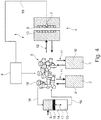
- a device 1 for performing the method according to the invention is shown schematically in FIG. 4 and has a temperature control device 2 with a heating device, at least one temperature control device 3 with a cooling device and an injection molding tool 4, actuators 5 and a control unit 6.
- the control unit 6 can have a regulating effect on the actuators 5, the control unit 6 processing signals as a function of a cavity wall temperature, which is determined, for example, by a temperature sensor 7 located in a cavity 8 of the injection molding tool 4.
- the temperature control device 2 with a heating device provides a relatively hot temperature control medium 9 in comparison to the temperature control device with a cooling device 3, which provides a relatively cold temperature control medium 10.
- the temperature control devices 2, 3 are connected to the actuators 5 via suitable pipelines (shown schematically by the arrows 11).
- the actuators 5 are connected to the injection molding tool 4 via suitable tubing or tubing (arrows 12).
- the injection molding tool 4 has at least one temperature control circuit 13 through which alternately hot temperature control medium 9 and cold temperature control medium 10 can be passed.
- the injection molding tool 4 it is also possible for the injection molding tool 4 to have two temperature control circuits 13 which are hydraulically separated from one another. One of the two temperature control circuits 13 serves to pass the cold temperature control medium 10 through, the other temperature control circuit serves to pass it through of the hot temperature control medium 9 through the injection molding tool 4 or an injection molding tool half.
- the device 1 preferably has a buffer 14 which holds a certain supply of hot temperature control medium 9 and a supply of cold temperature control medium 10.
- the buffer 14 is equipped with a displaceable piston element 15, which divides a buffer chamber into a partial space for hot temperature control medium 9 and a partial space for cold temperature control medium 10.
- the subspace containing hot temperature control medium 9 as well as the subspace containing cold temperature control medium 10 are each connected via suitable pipelines 16 to corresponding inputs of the actuators 5.
- By moving the piston 15 in the direction of the double arrow 17 an additional amount of cold temperature control medium 10 (movement of the piston 15 in Figure 4 down) or hot temperature control medium 9 (movement of the piston 15 in Figure 4 to the top) are fed into the temperature control circuits 13 via the actuators 5.
- the actuators 5 are, for example, an arrangement of different valves 18, which are only indicated schematically.
- the valves 18 are, for example, electrically controllable valves which are connected to the control unit 6 and can be controlled by it.
- either cold temperature control medium 10 or warm temperature control medium 9 can be fed into the temperature control circuits 13, whereby additional cold temperature control medium 10 or hot temperature control medium 9 can be fed in through buffer 14, for example to achieve high cooling or heating gradients.
- the provision of a buffer 14 makes it possible to use relatively small heating / cooling and / or pumping units for the temperature control devices 2, 3 and nevertheless to absorb syringe loads that occur in a learning and / or production cycle by means of the buffer 14. This helps to save energy and lowers the system costs.
- the temperature sensor 7 is connected to the control unit 6 via a suitable signal line 19. It is of course possible that a large number of temperature sensors 7 are arranged distributed over the cavity wall of the cavity 8 and send separate signals which represent a local cavity wall temperature to the control unit 6 or make them available to it.
- heating / cooling are also conceivable.
- electrical heating and / or cooling elements or gases can also be used as the temperature control medium.
- hot temperature control medium 9 is pumped through the cooling circuits 13 with a cool temperature control medium, the cavity wall of the cavity 8 will heat up.
- cold temperature control medium 10 is sent through the temperature control circuits 13.
- a method according to the invention for variothermal temperature control of the injection molding tool 4 is carried out in two phases, a learning phase A and a production phase B.
- learning phase A the temperature control characteristics of the system to be temperature controlled are determined, which at least include the injection molding tool 4, the temperature control devices 2, 3 and the corresponding (pipe) Line connections and the actuators 5 and the control unit 6 has.
- a temperature sensor 7 should be provided in the cavity 8 of the injection molding tool 4.
- This entire system which is to be temperature controlled (the injection mold 4) or to provide the temperature control (temperature control devices 2, 3, actuators 5 and the corresponding connections with the injection mold 4), has a certain temperature control characteristic, which, for example, is due to the shape of the cavity 8 is influenced in the injection mold 4. Further influencing variables can be the performance of the temperature control devices 2, 3 and the maximum possible flow rate of cold temperature control medium 10 and / or hot temperature control medium 9.
- Such a system made up of the above-mentioned components has a certain temperature control characteristic, that is, a certain temperature reaction of the cavity wall of the cavity 8 in the injection molding tool 4 takes place in response to a certain activity of the temperature control devices 2 or 3.
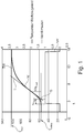
- Figure 1 shows a first partial step of this.
- the temperature control device 2 with heating device is switched on.
- the heating temperature control is switched on in the example shown according to Figure 1 at time t 1 .
- the graph VH (valve heating) is in Figure 1 and indicates a period of time in which the device 1 heats the injection molding tool.
- the graph TW indicates the temperature reaction on the cavity wall of the cavity 8, which is measured by the temperature sensor 7.
- the graph TW has an inflection point W in its course. To determine a characteristic variable for the temperature control characteristics of the system, it has proven useful to apply a tangent T to the graph TW at the turning point W.
- the maximum slope of the heating curve (graph TW) is present at the turning point W.
- the tangent forms an intersection point S with the abscissa.
- the period between the start of heating (time t 1 ) and the point of intersection S is defined as the delay time tu heat .
- the maximum slope of the tangent T is defined by a quotient of temperature and heating time, which is specified in "Kelvin per heating time (K / s heat )".
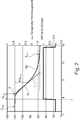
- the cooling characteristics of the injection molding tool 4 are determined analogously on the basis of a maximum achievable temperature T max (cf. Figure 2 ).
- a cooling curve (graph TK) is determined within the scope of determining the cooling characteristic, which can be reduced from the maximum injection mold temperature T max to a minimum achievable temperature T min .
- the temperature control device 2 warm temperature control device
- the temperature control device 3 with cool temperature control medium 10 is switched on.
- the activated cooling is shown with the graph VK.
- a tangent T is placed at the turning point W, the slope of which reflects the maximum cooling gradient. This cooling gradient can be specified in the unit Kelvin per cooling time (K / s cool ).
- This tangent also intersects the abscissa at the point of intersection S, so that a cooling delay time tu cool results, which results from the point in time t 1 (switching on the cooling unit) to the point of intersection S of the tangent T with the abscissa.
- This characterization of the heating and cooling behavior of the system is preferably carried out with an empty injection mold, that is to say still without any melt. As a result, it is not necessary to carry out the learning phase with an injection molding tool which is mounted on a plastic injection molding machine. Another advantage is that the use of plastic melt does not affect the mold temperature control characteristics or the system temperature control characteristics.
- the determined temperature control characteristics of the system are preferably stored in the form of tool-specific, in particular system-specific control values for actuators or otherwise assigned to the tool / system.
- a mean temperature T base can be calculated from this temperature control characteristic, for example by forming the difference between the maximum achievable temperature T max and the minimum achievable temperature T min.
- the process times t process1 for the heating case and the cooling case can be determined more precisely in order to achieve a setpoint temperature T setpoint1 based on a current injection mold temperature (cavity wall temperature T actMld ) as precisely as possible.
- the activation times of the heating device and / or the cooling device are corrected from one process to the next by corresponding start offset temperatures T startOffset or end temperature deviations T endOffset in order to include the start / end temperatures of the previous process at the beginning / end of one process consider.
- start offset temperatures T startOffest and T endOffset the corresponding offset times t startOffset and t endOffset can be determined for both heating and cooling.
- t startOffset T startOffset / K / s heat
- t endOffset T endOffset / K / s heat
- t startOffset T startOffset / K / s cool
- endOffset T endOffset / K / s cool
- the process time t process (x ) for the current process which is used for the current heating / cooling case. This enables learning for the current process from the ambient conditions and the sequence of the previous process.
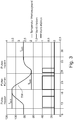
- the graph TW which indicates the mold temperature over time t, is in Figure 3 shown.
- Target temperatures T Soll1 and T Soll2 and T Soll3 are also specified.
- Switch-on times for the operation of the temperature control device 2 with a heating device and the temperature control device 3 with a cooling device are shown. Viewed from left to right, the temperature control device 2 with the heating device is switched on at a time t of approximately 10 seconds, so that the graph TW rises from this time (taking into account the time tu heat ) up to a setpoint temperature T 1 , which in Embodiment is approximately 109 °.
- the temperature of the injection molding tool 4 is kept approximately constant for a period of time.
- cooling begins by switching on the Temperature control device 3 with the cooling device, so that the tool is cooled from T Soll1 to a lower temperature T Soll2.
- T Soll3 a further target temperature
Landscapes
- Engineering & Computer Science (AREA)
- Manufacturing & Machinery (AREA)
- Mechanical Engineering (AREA)
- Physics & Mathematics (AREA)
- Health & Medical Sciences (AREA)
- Oral & Maxillofacial Surgery (AREA)
- Thermal Sciences (AREA)
- Injection Moulding Of Plastics Or The Like (AREA)
- Moulds For Moulding Plastics Or The Like (AREA)
Description
Die Erfindung betrifft ein Verfahren und eine Vorrichtung zur variothermen Temperierung von Spritzgießwerkzeugen.The invention relates to a method and a device for variothermal temperature control of injection molding tools.
Aus der
Aus der
Aus "
Aus "
Die variotherme Prozessführung ist mittlerweile Standard bei der Fertigung komplexer Spritzgießbauteile. Dabei wird die Werkzeugwandtemperatur während des Spritzgießzyklus auf verschiedenen Niveaus bewegt. Grundsätzlich werden durch eine höhere Werkzeugwandtemperatur verbesserte Fließeigenschaften bei der Formfüllung erreicht und dadurch folgende Effekte erzielt:
- verbesserte Abformung von mikrostrukturierten Oberflächen,
- Reduzierung der Sichtbarkeit von Bindenähten,
- verbesserter Glanz,
- Reduzierung von Schlierenbildung bei der Verarbeitung von gefüllten Werkstoffen,
- Unterstützung bzw. Beschleunigung der Aushärtereaktion von reaktiven Kunststoffen,
- Reduzierung von Einspritzdruck und Schließkraft,
- verbesserte Maßhaltigkeit und Toleranz der erzeugten Formteile.
- improved molding of microstructured surfaces,
- Reducing the visibility of weld lines,
- improved shine,
- Reduction of streak formation when processing filled materials,
- Support or acceleration of the curing reaction of reactive plastics,
- Reduction of injection pressure and clamping force,
- improved dimensional accuracy and tolerance of the molded parts produced.
Auf der anderen Seite führen höhere Wandtemperaturen zu einer Verlängerung der notwendigen Kühlzeit und verschlechtern damit die Wirtschaftlichkeit des Verfahrens aufgrund geringerer Ausbringung. Durch den Einsatz der variothermen Temperierung kann diesem Nachteil entgegengewirkt werden, indem ein weiterer Temperierkreislauf auf einem tieferen Temperaturniveau dazu genutzt wird, die Kavität und/oder Teilbereiche davon aktiv zu kühlen und somit die Wärmeabfuhr aus dem Formteil zu beschleunigen. Daneben kann es erforderlich sein, das Bauteil für eine bessere Entformbarkeit auf ein tieferes Temperaturniveau zu kühlen. Um die Energieeffizienz und die Dynamik des Systems zu verbessern, werden variotherm temperierte Formeinsätze idealerweise mit einem konturfolgenden, kavitätsnahen Temperiersystem ausgelegt, um die variotherme Masse so weit wie möglich zu reduzieren. Es ist somit wünschenswert, beispielsweise Heizkanäle oder Kühlkanäle sehr nahe an der Kavität in der Wand anzuordnen, so dass aufgrund geringer Werkzeugwandstärken eine hohe Dynamik erreichbar ist.On the other hand, higher wall temperatures lead to an extension of the necessary cooling time and thus worsen the economic efficiency of the process due to lower output. Using variothermal temperature control, this disadvantage can be counteracted by using a further temperature control circuit at a lower temperature level to actively cool the cavity and / or parts of it and thus accelerate the dissipation of heat from the molded part. In addition, it may be necessary to cool the component to a lower temperature level for better demoldability. In order to improve the energy efficiency and the dynamics of the system, variothermal temperature-controlled mold inserts are ideally designed with a contour-following, cavity-related temperature control system in order to reduce the variothermal mass as much as possible. It is therefore desirable, for example, to arrange heating channels or cooling channels very close to the cavity in the wall, so that a high level of dynamics can be achieved due to the small tool wall thickness.
Auf dem Markt sind mittlerweile unterschiedliche Technologien für die variotherme Temperierung von Formeinsätzen verfügbar. Dazu gehören werkzeugexterne oder -interne elektrische und/oder induktive Heizsysteme, Systeme mit Wasserkühlung, Zwei- und/oder. Dreikreisfluidsysteme auf Öl- oder Wasserbasis, CO2-Temperier-systeme, externe Laser und Systeme mit Dampfheizung.Various technologies for variothermal temperature control of mold inserts are now available on the market. These include external or internal electrical and / or inductive heating systems, systems with water cooling, dual and / or. Three-circuit fluid systems based on oil or water, CO2 temperature control systems, external lasers and systems with steam heating.
Für eine weitere Verbesserung der Effizienz wird bei Wasser-Wasser- und auch bei Öl-Öl-Systemen ein Zwischenspeicher eingesetzt, um das Temperiermedium in den geschlossenen Heiz- und Kühlkreisläufen hydraulisch zu trennen und eine Vermischung von heißem und kaltem Medium nach Möglichkeit zu vermeiden. Allen Verfahren ist gemeinsam, dass dem Werkzeug zyklisch Energie zugeführt und anschließend wieder aus dem Werkzeug abgeführt werden muss.To further improve efficiency, an intermediate storage device is used in water-water and oil-oil systems in order to hydraulically separate the temperature control medium in the closed heating and cooling circuits and, if possible, to avoid mixing of hot and cold medium. What all the processes have in common is that energy must be fed to the tool cyclically and then removed from the tool again.
Die Dynamik eines variotherm zu betreibenden Werkzeugs ergibt sich im Wesentlichen aus der Vorlauftemperatur, der Durchflussmenge pro Zeiteinheit, dem Druck des Mediums, der Anordnung der Temperierkanäle und der Heizleistung der Temperiergeräte sowie der variotherm zu temperierenden Masse des Werkzeuges. Keines der genannten Wasser-Wasser-Variotherm-Systeme bietet die Möglichkeit die Werkzeugwandtemperatur zu regeln. Es wird lediglich zur bestimmten, vorher einmal festgelegten Zeitpunkt ein heißes oder kaltes Medium in den Werkzeugkreislauf geschickt. Die Veränderung der Werkzeugwandtemperatur wird also lediglich gesteuert. Sinnvollerweise besitzt jedes Formwerkzeug für den variothermen Betrieb jedoch einen Temperaturfühler an der Werkzeugwand. An diesem Ort ist die Führung der Temperatur aus prozesstechnischer Sicht entscheidend.The dynamics of a variothermically operated tool results essentially from the flow temperature, the flow rate per unit of time, the pressure of the medium, the arrangement of the temperature control channels and the heating power of the temperature control devices as well as the variothermically temperature controlled mass of the tool. None of the mentioned water-water Variotherm systems offer the possibility of regulating the mold wall temperature. A hot or cold medium is only sent into the tool circuit at a specific, previously determined time. The change in the mold wall temperature is only controlled. It makes sense, however, for every molding tool for variothermal operation to have a temperature sensor on the tool wall. From a process engineering point of view, maintaining the temperature is crucial at this location.
Mit derartigen bekannten Systemen können Umwelteinflüsse, wie z. B. die Hallentemperatur, die Vorlauftemperatur des Hallenwassers und der Verschleiß des Werkzeuges oder des Temperiergerätes, z. B. Verkalkung, Korrosion und/oder sich ändernden Pumpenleistung etc. Einfluss auf die Heiz- und Kühlleistung der variothermen Anlage nehmen. Im bekannten, konventionellen gesteuerten Betrieb gemäß dem Stand der Technik wird dies lediglich durch die Überwachung von Werkzeugwandtemperaturverläufen erkennbar. Die Anlage selbst kann jedoch derartige Langzeitveränderungen nicht ausgleichen, was zu Schwankungen im Temperaturverlauf am Werkzeug führt. Dies kann insbesondere dann von Nachteil sein, wenn komplexe Verarbeitungsprozesse vorliegen und hohe Genauigkeiten des Systems gefordert sind.With such known systems, environmental influences such. B. the hall temperature, the flow temperature of the hall water and the wear of the tool or the temperature control device, z. B. calcification, corrosion and / or changing pump performance etc. influence the heating and cooling performance of the variothermal system. In the known, conventional controlled operation according to the prior art, this can only be recognized by monitoring the mold wall temperature profiles. However, the system itself cannot compensate for such long-term changes, which leads to fluctuations in the temperature profile on the tool. This can be particularly disadvantageous when complex processing processes are involved and high levels of accuracy are required from the system.
Es ist weiterhin bekannt, eine sogenannte Einspritzfreigabe zu geben, wenn ein einstellbares Temperaturniveau an einem Werkzeugwandfühler erreicht wird. In der Praxis kommt es allerdings zu Überschwingern der Temperatur, die insbesondere bei Artikeln mit langen Einspritzzeiten merklich ins Gewicht fallen und die Qualität des Formteils negativ beeinflussen. Je größer der Überschwinger der Temperatur über ein erforderliches Niveau wird, desto langsamer wird dem Bauteil Energie entzogen, was zu einer Verlängerung der Zykluszeit führt. Ebenso wird der Energieverbrauch höher, da wieder von einem höheren Temperaturniveau aus heruntergekühlt werden muss.It is also known to give a so-called injection release when an adjustable temperature level is reached on a mold wall sensor. In practice, however, the temperature overshoots, which is noticeably significant, especially in the case of articles with long injection times, and has a negative impact on the quality of the molded part. The greater the overshoot of the temperature above a required level, the slower energy is extracted from the component, which leads to an increase in the cycle time. The energy consumption is also higher because it has to be cooled down again from a higher temperature level.
Bei bekannten Steuerungen ist eine erhebliche Erfahrung und Verantwortung des Bedieners erforderlich, in Abhängigkeit der Komplexität und der Qualitätsanforderungen an das Formteil, die entsprechenden Auslöseschwellwerte manuell einzustellen, um entsprechende Kommunikationssignale abzustimmen. Nachteilig ist hier insbesondere, dass durch die Zunahme an Komplexität der Steuerungen auch ein zeitlicher Mehraufwand bei der Einrichtung des Prozesses in Kauf zu nehmen ist.With known controls, considerable experience and responsibility on the part of the operator are required, depending on the complexity and the quality requirements of the molded part, to manually set the corresponding trigger threshold values in order to coordinate corresponding communication signals. A particular disadvantage here is that the increased complexity of the controls means that additional expenditure in terms of time is to be accepted when setting up the process.
Aus der
Aus der
Aus der
Aufgabe der Erfindung ist es, ein Verfahren zur variothermen Temperierung von Spritzgießwerkzeugen anzugeben, welches eine deutlich verbesserte Prozessführung bei deutlich verbesserten Bauteilqualitäten zulässt, auch wenn Randbedingungen, wie z. B. Schwankungen der Schmelzetemperatur und Umgebungsparameter wie z. B. Hallentemperatur oder dergleichen, schwanken.The object of the invention is to provide a method for variothermal temperature control of injection molding tools, which allows a significantly improved process control with significantly improved component quality, even if boundary conditions such. B. fluctuations in the melt temperature and environmental parameters such. B. hall temperature or the like, fluctuate.
Das Verfahren soll in der Lage sein, selbstständig die Temperierung der Spritzgießwerkzeuge an sich im Produktionsverlauf ändernde Parameter anzupassen, um so eine verbesserte Qualitätskonstanz der Formteile sicherzustellen.The method should be able to independently adapt the temperature control of the injection molding tools to parameters that change in the course of production in order to ensure improved quality constancy of the molded parts.
Des Weiteren ist es Aufgabe der Erfindung, ein variothermes Temperierverfahren von Spritzgießwerkzeugen anzugeben, welches weitgehend unabhängig von Spezialkenntnissen und/oder Bedienerfahrungen von Bedienpersonal ist. Es soll insbesondere in der Lage sein, ausgehend von einem vorab festgelegten Temperaturverlauf eines Spritzgießwerkzeuges bzw. eines Temperiersystems während des Spritzgießzykluses selbstständig und vollautomatisch einer Idealtemperaturführung während einer Produktionsphase möglichst nahe zu kommen.A further object of the invention is to specify a variothermal temperature control method for injection molding tools which is largely independent of special knowledge and / or operator experience of operating personnel. In particular, it should be able to independently and fully automatically come as close as possible to an ideal temperature control during a production phase on the basis of a predetermined temperature profile of an injection molding tool or a temperature control system during the injection molding cycle.
Diese Aufgaben werden mit einem Verfahren zur variothermen Temperierung eines Spritzgießwerkzeuges mit den Merkmalen des Anspruchs 1 gelöst. Vorteilhafte Ausführungsformen sind in den vom Anspruch 1 abhängigen Unteransprüchen angegeben.These objects are achieved with a method for variothermal temperature control of an injection molding tool with the features of
Das erfindungsgemäße Verfahren zur variothermen Temperierung eines Spritzgießwerkzeuges unter Verwendung einer Temperiervorrichtung weist zumindest die folgenden Schritte auf:
- A) In einer Lernphase:
- Ermitteln einer Temperiercharakteristik des zu temperierenden Systems umfassend zumindest das Spritzgießwerkzeug und die Temperiervorrichtung zum Erhalt von systemindividuellen Stellwerten, mit denen Stellglieder der Temperiervorrichtung zur Erreichung eines Soll-Temperaturprofiles angesteuert werden können und
- B) In einer Produktionsphase:
- Temperierung des Spritzgießwerkzeuges mit den in der Lernphase ermittelten Stellwerten;
- Ermittlung von Abweichungen eines Ist-Temperaturprofiles des Spritzgießwerkzeuges gegenüber dem Soll-Temperaturprofil während des Produktionszyklus und berechnen korrigierter Stellwerte bzw. Stellzeiten für die Stellglieder aus diesen Abweichungen;
- Durchführen eines darauffolgenden Produktionsprozesses mit den korrigierten Stellwerten.
- A) In a learning phase:
- Determining a temperature control characteristic of the system to be temperature controlled including at least the injection molding tool and the temperature control device to obtain system-specific control values with which actuators of the temperature control device can be controlled to achieve a target temperature profile and
- B) In a production phase:
- Temperature control of the injection molding tool with the control values determined in the learning phase;
- Determination of deviations of an actual temperature profile of the injection molding tool compared to the target temperature profile during the production cycle and calculation of corrected control values or control times for the actuators from these deviations;
- Carrying out a subsequent production process with the corrected control values.
Somit wird zunächst in einer Lernphase, in Abhängigkeit der eingesetzten Temperiervorrichtung und des bauteilspezifischen Spritzgießwerkzeuges systemindividuell das zu temperierende System charakterisiert, was insbesondere die Temperierdynamik, also die Temperarturreaktion des Spritzgießwerkzeuges im Falle eines Heizens oder Kühlens desselben mit umfasst. In Kenntnis dieser systemindividuellen Temperiercharakteristik und auch in Kenntnis von bauteilspezifischen Temperieranforderungen, die z. B. aus Erfahrungswerten eines Prozessentwicklers/-designers hergeleitet werden können, wird ein Soll-Temperaturprofil des Spritzgießwerkzeuges angesteuert. Dieses Soll-Temperaturprofil findet seinen Niederschlag in systemindividuellen Stellwerten, die zur Ansteuerung von Stellgliedern der Temperiervorrichtung verwendet werden, um das Soll-Temperaturprofil zu erreichen.Thus, in a learning phase, depending on the temperature control device used and the component-specific injection molding tool, the system to be temperature-controlled is characterized individually, which in particular includes the temperature control dynamics, i.e. the temperature reaction of the injection molding tool in the case of heating or cooling of the same. With knowledge of these system-specific temperature control characteristics and also with knowledge of component-specific temperature control requirements, such. B. can be derived from empirical values of a process developer / designer, a target temperature profile of the injection molding tool is controlled. This target temperature profile is reflected in system-specific ones Control values that are used to control actuators of the temperature control device in order to achieve the target temperature profile.
Ausgehend von diesen systemindividuellen Stellwerten wird dann in einer Produktionsphase, in der mit dem Spritzgießwerkzeug Formteile hergestellt werden, die Temperierung des Spritzgießwerkzeuges durchgeführt. Hierbei entstehen üblicherweise Abweichungen eines Ist-Temperaturprofils des Spritzgießwerkzeuges vom Soll-Temperaturprofil des Spritzgießwerkzeuges. Diese Abweichungen werden während der Produktionsphase ab dem ersten Zyklus der Produktionsphase ermittelt. In Kenntnis der Temperiercharakteristik des zu temperierenden Systems, welche in der Lernphase ermittelt wurde, können in guter Näherung korrigierte Stellwerte aus den Abweichungen des Ist-Temperaturprofils des Spritzgießwerkzeuges vom Soll-Temperaturprofil des Spritzgießwerkzeuges berechnet werden. Mit diesen korrigierten Stellwerten wird dann der darauffolgende Produktionsprozess, z. B. der auf den ersten Produktionsprozess folgende zweite Produktionsprozess durchgeführt. Auch während dieses Produktionsprozesses werden wiederum Abweichungen des Ist-Temperaturprofils gegenüber dem Soll-Temperaturprofil ermittelt und erneut korrigierte Stellwerte zur Ansteuerung der Stellglieder der Temperiervorrichtung berechnet. Mit den erneut korrigierten Stellwerten wird in einem darauffolgenden Produktionsprozess die Temperiervorrichtung angesteuert. Dieses Vorgehen wird für die weiteren Produktionsprozesse (Zyklen) beibehalten. Somit erfolgt also während der Produktionsphase iterativ ein stetiger weiterer Anpassungsvorgang der Stellwerte, bis in der Produktionsphase das Ist-Temperaturprofil möglichst genau und möglichst nahe mit dem Soll-Temperaturprofil zusammenfällt. In der Produktionsphase erfolgt somit ein stetiges iteratives Annähern des Ist-Temperaturprofils an das Soll-Temperaturprofil.On the basis of these system-specific control values, the temperature of the injection molding tool is then carried out in a production phase in which molded parts are produced with the injection molding tool. This usually results in deviations of an actual temperature profile of the injection molding tool from the target temperature profile of the injection molding tool. These deviations are determined during the production phase from the first cycle of the production phase. Knowing the temperature control characteristics of the system to be temperature controlled, which was determined in the learning phase, corrected control values can be calculated to a good approximation from the deviations of the actual temperature profile of the injection molding tool from the target temperature profile of the injection molding tool. The subsequent production process, e.g. B. carried out the second production process following the first production process. During this production process, too, deviations in the actual temperature profile from the setpoint temperature profile are determined, and corrected control values for controlling the actuators of the temperature control device are calculated again. The temperature control device is controlled in a subsequent production process with the newly corrected control values. This procedure is retained for the further production processes (cycles). Thus, during the production phase, a continuous further adjustment process of the control values takes place iteratively until the actual temperature profile coincides as precisely and as closely as possible with the setpoint temperature profile in the production phase. In the production phase, there is a constant iterative approximation of the actual temperature profile to the target temperature profile.
Treten nunmehr während der Produktionsphase, die eine Vielzahl von aufeinanderfolgenden Produktionsprozessen (Zyklen) umfasst, Abweichungen von Randbedingungen, die Einfluss auf den Betrieb der Spritzgießmaschine zusammen mit dem Spritzgießwerkzeug haben können, auf, so wird sich dies in einem geänderten Ist-Temperaturprofil niederschlagen. Ein solches, sich auch schleichend änderndes Ist-Temperaturprofil kann dann mit dem erfindungsgemäßen Verfahren wieder an das Soll-Temperaturprofil angenähert werden. Hierdurch werden z. B. qualitätsmindernde Störeinflüsse wie z. B. Temperaturschwankungen in der Schmelze oder Schwankungen in der Umgebungstemperatur oder dergleichen über die Vielzahl der Produktionszyklen (Produktionsprozesse) ausgeglichen und minimiert. Dies hat zur Folge, dass eine erhöhte Bauteilqualität erreichbar ist, ohne dass ein manuelles Eingreifen eines Bedieners erforderlich ist.If deviations from boundary conditions occur during the production phase, which includes a large number of successive production processes (cycles), which can influence the operation of the injection molding machine together with the injection molding tool, this will be reflected in a changed actual temperature profile. Such an actual temperature profile, which also gradually changes can then be approximated again to the target temperature profile with the method according to the invention. This z. B. quality-reducing interference such. B. Temperature fluctuations in the melt or fluctuations in the ambient temperature or the like over the large number of production cycles (production processes) balanced and minimized. As a result, an increased component quality can be achieved without manual intervention by an operator being necessary.
Eine Spritzgießmaschine, die nach dem erfindungsgemäßen Verfahren arbeitet, kann somit selbstständig, also vollautomatisch, eine optimale variotherme Temperierung auch über einen längeren Zeitraum während einer Produktionsphase gewährleisten.An injection molding machine that works according to the method according to the invention can thus independently, ie fully automatically, ensure optimal variothermal temperature control even over a longer period of time during a production phase.
Eine besondere Ausführungsform des erfindungsgemäßen Verfahrens ist dadurch gekennzeichnet, dass
- A1) zum Ermitteln einer Temperiercharakteristik des zu temperierenden Systems;
ein Berechnen von Ansteuerzeiten für Heiz- und/oder Kühlvorrichtungen der Temperiervorrichtung zur Erreichung eines zeitlichen Soll-Temperaturprofils des Spritzgießwerkzeuges für ein herzustellendes Formteil erfolgt; - A2) eine Evaluation des Soll-Temperaturprofils in mindestens einem Evaluierungszyklus und bedarfsweises Korrigieren der Ansteuerungszeiten durchgeführt wird und
- A3) ein Speichern zumindest der korrigierten Ansteuerzeiten aus Schritt A3) als Stellwerte für das zu temperierende System, insbesondere dessen Stellglieder erfolgt und
- B1) während eines ersten Produktionszyklus ein Abfahren des Temperaturprofils mit den Stellwerten aus Schritt A3) erfolgt;
- B2) ein Ermitteln der Ist-Temperaturen und ein Vergleich mit korrespondierenden Soll-Temperaturen des Soll-Temperaturprofiles des Spritzgießwerkzeuges erfolgt;
- B3) eine Berechnung korrigierter Stellwerte, nämlich Ansteuerzeiten für die Stellglieder des darauffolgenden Produktionszyklus aus Abweichungen ermittelt im Schritt B2) erfolgt und
- B4) ein Durchführen des darauffolgenden Produktionszyklus mit den korrigierten Ansteuerzeiten aus Schritt B3) erfolgt und
- B5) die Schritte B2) bis B5) während weiterer Produktionszyklen wiederholt werden.
- A1) for determining a temperature control characteristic of the system to be temperature controlled;
a calculation of activation times for heating and / or cooling devices of the temperature control device takes place in order to achieve a temporal target temperature profile of the injection molding tool for a molded part to be produced; - A2) an evaluation of the target temperature profile is carried out in at least one evaluation cycle and, if necessary, the activation times are corrected, and
- A3) at least the corrected activation times from step A3) are stored as control values for the system to be temperature-controlled, in particular its actuators, and
- B1) during a first production cycle, the temperature profile is followed with the control values from step A3);
- B2) the actual temperatures are determined and a comparison with corresponding target temperatures of the target temperature profile of the injection molding tool takes place;
- B3) a calculation of corrected control values, namely activation times for the actuators of the subsequent production cycle determined from deviations in step B2) takes place and
- B4) the subsequent production cycle is carried out with the corrected control times from step B3) and
- B5) steps B2) to B5) are repeated during further production cycles.
Durch eine mehrstufige Ermittlung der Ansteuerzeiten, insbesondere der hierzu korrespondierenden Stellwerte, wird bereits in der Lernphase eine ziemlich genaue Angleichung des Ist-Temperaturprofils an das gewünschte Soll-Temperaturprofil erreicht, wobei in der Produktionsphase zudem das bereits oben beschriebene laufende Optimierungsprogramm bevorzugt in jedem Spritzgießzyklus durchgeführt wird, welches dann in der Lage ist, variierende und/oder schwankende Umgebungsbedingungen (Randbedingungen), die gegebenenfalls einen negativen Einfluss auf die Bauteilqualität haben können, mittels einer genau angepassten Werkzeugtemperierung auszugleichen.Through a multi-stage determination of the control times, in particular the corresponding control values, a fairly precise adjustment of the actual temperature profile to the desired target temperature profile is already achieved in the learning phase, with the ongoing optimization program already described above preferably being carried out in each injection molding cycle in the production phase which is then able to compensate for varying and / or fluctuating environmental conditions (boundary conditions), which can possibly have a negative influence on the component quality, by means of a precisely adapted mold temperature control.
Als Heiz- und/oder Kühleinrichtungen der Temperiervorrichtung können vorteilhafterweise zumindest eine oder eine Kombination aus der Gruppe:
- Wasserheiz- und/oder Wasserkühleinrichtung;
- Ölheiz- und/oder Ölkühleinrichtung;
- elektrische Heiz- und/oder elektrische Kühleinrichtung;
- Heiz- und/oder Kühlpatronen;
- Heizeinrichtungen auf Induktionsbasis oder mittels Laser sowie keramische Heizungen;
- Kältemittelkühlvorrichtungen und/oder CO2-Kühlvorrichtungen und/oder eine Kühlung mittels eines Gases, z. B. Luft;
- Heizvorrichtung und/oder Kühlvorrichtung auf der Basis eines Wärmeträgeröles und/oder Heißdampfes
- Water heating and / or water cooling equipment;
- Oil heating and / or oil cooling equipment;
- electric heating and / or electric cooling equipment;
- Heating and / or cooling cartridges;
- Induction-based or laser-based heating devices and ceramic heaters;
- Refrigerant cooling devices and / or CO 2 cooling devices and / or cooling by means of a gas, e.g. B. Air;
- Heating device and / or cooling device based on a heat transfer oil and / or superheated steam
Das erfindungsgemäße Verfahren ist unabhängig von der Art der Heiz- und/oder Kühleinrichtungen mit Vorteil einsetzbar. Somit ist auch eine große Variabilität hinsichtlich der Einsetzbarkeit des erfindungsgemäßen Verfahrens in unterschiedlichen Spritzgießwerkzeugtypen oder Spritzgießwerkzeugkonzepten möglich.The method according to the invention can advantageously be used regardless of the type of heating and / or cooling devices. Thus, great variability is also possible with regard to the applicability of the method according to the invention in different injection molding tool types or injection molding tool concepts.
Soweit angegeben ist, dass als Stellwerte Ansteuerzeiten für Heiz- und/oder Kühleinrichtungen ermittelt und im weiteren Verlauf verwendet werden, so können selbstverständlich in Abhängigkeit der genutzten Heiz- und/oder Kühleinrichtungen auch andere Parameter als die Ansteuerzeit verwendet werden. So ist es beispielsweise ohne weiteres möglich, bei Verwendung von elektrischen Heiz- und/oder Kühleinrichtungen statt den Ansteuerzeiten beispielsweise die Stromstärken oder andere Parameter, welche die Heizleistung/Kühlleistung der verwendeten Heizeinrichtung/Kühleinrichtung beeinflussen, zu verwenden. So ist es beispielsweise auch machbar, bei Verwendung von Heiz- und/oder Kühleinrichtungen, die ein Heizund/oder Kühlmedium nutzen, anstelle der Ansteuerzeit, mit der üblicherweise die Durchflussdauer des Heiz- und/oder Kühlmediums beeinflusst wird, auch Maßnahmen vorzusehen, mit denen die Durchflussmenge des Mediums beeinflusst wird. Hieraus können gegebenenfalls Stellwerte in Form von Ansteuersignalen für entsprechende Pumpen oder andere den Volumenstrom des Mediums beeinflussende Gerätschaften ergeben.If it is stated that control times for heating and / or cooling devices are determined as control values and used in the further course, parameters other than the control time can of course also be used depending on the heating and / or cooling devices used. For example, when using electrical heating and / or cooling devices, it is easily possible to use, for example, the current strengths or other parameters that influence the heating / cooling capacity of the heating / cooling device used instead of the control times. For example, when using heating and / or cooling devices that use a heating and / or cooling medium, it is also feasible, instead of the control time, with which the flow duration of the heating and / or cooling medium is usually influenced, to provide measures with which the flow rate of the medium is influenced. From this, if necessary, control values in the form of control signals for corresponding pumps or other equipment influencing the volume flow of the medium can result.
Es hat sich weiterhin als vorteilhaft herausgestellt, den Schritt A) des erfindungsgemäßen Verfahrens bzw. die Schrittfolge A1) bis A3) während der Lernphase ohne Befüllung des Spritzgießwerkzeuges mit Formmasse durchzuführen. Hierdurch wird erreicht, dass alleine die Temperiercharakteristik des zu temperierenden Systems ermittelbar ist, ohne dass Einflüsse der Schmelze diese Ermittlung beeinträchtigen könnte.It has also been found to be advantageous to carry out step A) of the method according to the invention or the sequence of steps A1) to A3) during the learning phase without filling the injection molding tool with molding compound. This ensures that only the temperature control characteristics of the system to be temperature controlled can be determined without the influence of the melt being able to impair this determination.
Außerdem ist vorteilhaft, dass eine solche Ermittlung der Temperiercharakteristik in einem z. B. standardisierten Versuchsaufbau durchgeführt werden kann. Eine Montage des zu temperierenden Systems auf einer Spritzgießmaschine ist hierbei nicht erforderlich. Somit kann beispielsweise unter Laborbedingungen die Temperiercharakteristik des zu temperierenden Systems ohne gegebenenfalls nachteilige und schwankende Außenumstände ermittelt werden.It is also advantageous that such a determination of the temperature control characteristics in a z. B. standardized test setup can be carried out. It is not necessary to mount the system to be temperature-controlled on an injection molding machine. Thus, for example, the temperature control characteristics can be adjusted under laboratory conditions of the system to be temperature controlled can be determined without any disadvantageous and fluctuating external circumstances.
Weiterhin ist es zweckmäßig, in einem derart standardisierten Versuchsaufbau ermittelte Stellwerte für das im Lernprozess behandelte zu temperierende System als temperiersystemspezifische Stellwerte dem zu temperierenden System zuzuordnen und gegebenenfalls geeignet abzuspeichern. Mit derartigen temperiersystemspezifischen Stellwerten kann dann ohne weiteres das zu temperierende System, also zumindest das Spritzgießwerkzeug und die Temperiervorrichtung, in guter Näherung beispielsweise bei einer Erstinbetriebnahme auf einer Spritzgießmaschine betrieben werden und sofort mit dem Produktionsprozess begonnen werden. Während des Produktionsprozesses erfolgt dann - wie vorbeschrieben - eine weitere iterative Annäherung an den vorgegebenen Idealtemperaturverlauf im Spritzgießwerkzeug.Furthermore, it is expedient to assign control values determined in such a standardized test setup for the system to be temperature-controlled which is treated in the learning process as temperature-control-system-specific control values to the system to be temperature-controlled and, if necessary, to store them in a suitable manner. With such temperature control system-specific control values, the system to be temperature controlled, i.e. at least the injection molding tool and the temperature control device, can then be operated in good approximation, for example during initial commissioning on an injection molding machine, and the production process can be started immediately. During the production process - as described above - a further iterative approximation to the specified ideal temperature profile in the injection molding tool then takes place.
In einer weiteren Ausführungsform des erfindungsgemäßen Verfahrens wird zur Ermittlung der Temperiercharakteristik des zu temperierenden Systems mindestens bestehend aus einer Heizvorrichtung, einer Kühlvorrichtung, einem Stellglied für das Medium und einem Spritzgießwerkzeug eine minimal erreichbare Wandtemperatur (Tmin) einer Kavität des Spritzgießwerkzeuges ermittelt und gespeichert. In a further embodiment of the method according to the invention, a minimum attainable wall temperature (T min ) of a cavity of the injection molding tool is determined and stored to determine the temperature control characteristics of the system to be temperature controlled at least consisting of a heating device, a cooling device, an actuator for the medium and an injection molding tool.
Außerdem wird zur Ermittlung der Temperiercharakteristik des zu temperierenden Systems mindestens bestehend aus einem Heizgerät, einem Kühlgerät, mindestens einem Stellglied hierfür und einem Spritzgießwerkzeug eine maximal erreichbare Wandtemperatur (Tmax) einer Kavität des Spritzgießwerkzeuges ermittelt und gespeichert. In addition, a maximum attainable wall temperature (T max ) of a cavity of the injection molding tool is determined and stored to determine the temperature control characteristics of the system to be temperature controlled, consisting of at least a heater, a cooling device, at least one actuator for this and an injection molding tool.
Diese beiden Maßnahmen stellen die ersten Schritte dar, um die Temperiercharakteristik des zu temperierenden Systems hinsichtlich der maximal und der minimal erreichbaren Temperaturen einzugrenzen. Innerhalb dieses Temperaturfensters zwischen Tmin und Tmax kann somit eine variotherme Temperierung des zu temperierenden Systems, insbesondere des Spritzgießwerkzeuges, erfolgen.These two measures represent the first steps to limit the temperature control characteristics of the system to be temperature controlled with regard to the maximum and minimum temperatures that can be achieved. Variothermal tempering of the system to be tempered, in particular of the injection molding tool, can thus take place within this temperature window between T min and T max.
Zur Ermittlung der Temperierdynamik wird vorteilhaft weiterhin während des Aufheizvorgangs die maximale Steigung einer Aufheizkurve zwischen Tmin und Tmax, welche an deren Wendepunkt liegt, ermittelt und die maximale Steigung in der Einheit Kelvin pro Sekunde (K/sheat) für die Betriebsart "Puls-Heizen" bestimmt.To determine the temperature dynamics, the maximum slope of a heating curve between T min and T max , which is at the turning point, is advantageously determined during the heating process and the maximum slope in the unit Kelvin per second (K / s heat ) for the "pulse" operating mode -Heating "determined.
Dies kann beispielsweise dadurch geschehen, dass an den Wendepunkt der Aufheizkurve eine Tangente an die Aufheizkurve gelegt wird und ein Schnittpunkt der Tangente mit der Abszisse gebildet wird, wobei als Verzugszeit tuheat der zeitliche Abstand zwischen dem Beginn der Heizung und dem Schnittpunkt der Tangente mit der Abszisse definiert wird. Durch diese Maßnahme und insbesondere in Abhängigkeit der entstehenden Verzugszeit tuheat kann die Temperierdynamik des zu temperierenden Systems, die u. a. einen wesentlichen Punkt der Gesamttemperiercharakteristik darstellt, ermittelt werden.This can be done, for example, by placing a tangent on the heating curve at the turning point of the heating curve and forming an intersection of the tangent with the abscissa, with the delay time tu heat being the time interval between the start of heating and the intersection of the tangent with the Abscissa is defined. Through this measure and in particular as a function of the resulting delay time tu heat , the temperature control dynamics of the system to be temperature controlled, which among other things represents an essential point of the overall temperature control characteristic, can be determined.
Analog zum Aufheizvorgang wird ausgehend von der maximal erreichbaren Temperatur Tmax die Kühlung bei abgeschalteter Heizung gestartet, wobei die maximale negative Steigung in Kelvin pro Sekunde am Wendepunkt der Kühlkurve bestimmt wird (K/scool) und an den Wendepunkt der Kühlkurve eine Tangente gelegt wird. Der Schnittpunkt der Tangente mit der Abszisse wird ermittelt und eine Verzugszeit tucool als zeitlicher Abstand zwischen dem Beginn der Kühlung und dem Schnittpunkt der Tangente mit der Abszisse definiert.Analogous to the heating process, starting from the maximum achievable temperature T max, the cooling is started with the heating switched off, whereby the maximum negative slope in Kelvin per second is determined at the turning point of the cooling curve (K / s cool ) and a tangent is placed at the turning point of the cooling curve . The point of intersection of the tangent with the abscissa is determined and a delay time tu cool is defined as the time interval between the start of cooling and the point of intersection of the tangent with the abscissa.
Durch diese Maßnahmen kann die Temperierdynamik für die Betriebsart "Puls-Kühlen" (Kühldynamik) des zu temperierenden Systems gut ermittelt werden. Dies erlaubt Aussagen über die Kühlcharakteristik des zu temperierenden Systems.By means of these measures, the temperature control dynamics for the "pulse cooling" operating mode (cooling dynamics) of the system to be temperature controlled can be determined well. This allows statements to be made about the cooling characteristics of the system to be temperature controlled.
Weiterhin ist es vorteilhaft eine mittlere Temperatur TBasis zwischen der minimalen Temperatur Tmin und der maximalen Temperatur Tmax zu berechnen. Diese kann als Ausgangspunkt für weitere Berechnungen verwendet werden.Furthermore, it is advantageous to calculate an average temperature T basis between the minimum temperature T min and the maximum temperature T max. This can be used as a starting point for further calculations.
Beispielsweise kann aus der Formel mit ![]()
errechnet werden.For example, from the formula with![]()
can be calculated.
Mit dieser Berechnung wird somit eine bestimmte Zeitspanne für den Betrieb der Heizeinrichtung errechnet, um von der minimalen Temperatur (Tmin) bis zur mittleren Temperatur (TBasis) zu gelangen, wobei die Verzögerungszeit (tuheat) bereits eingerechnet ist und somit die ermittelte Ansteuerzeit bereits temperierdynamische Aspekte des zu temperierenden Systems berücksichtigt.With this calculation, a certain period of time for the operation of the heating device is calculated in order to get from the minimum temperature (T min ) to the average temperature (T Basis ), the delay time (tu heat ) and thus the determined control time being already included temperature-dynamic aspects of the system to be temperature-controlled have already been taken into account.
Weiterhin ist es vorteilhaft, dass nach dem Abschalten der Heizung, das heißt nach Ablauf der Zeit (tbasisheat) eine Zeitspanne gemessen wird, bis keine weitere signifikante Temperaturänderung am Werkzeugwandfühler mehr auftritt, wobei eine Temperatur (Tbasisheat) und eine Nachschwingzeit (Totzeit) (tBasisheatdead) gemessen und gespeichert wird.Furthermore, it is advantageous that after the heating has been switched off, i.e. after the time has elapsed (t base heat ), a period of time is measured until no further significant temperature change occurs at the tool wall sensor , with a temperature (T base heat) and a post-oscillation time (dead time). (t base beatdead ) is measured and saved.
Hierdurch kann der Effekt des Nachheizens, nachdem die Abschaltung der Heizung bereits erfolgt ist, gut ermittelt werden und Voraussagen getroffen werden, wie lange sich das Werkzeug noch erwärmt, obwohl die Heizung bereits abgeschaltet ist.This makes it possible to determine the effect of the post-heating after the heating has already been switched off and predict how long the tool will continue to heat up even though the heating has already been switched off.
Mit einer solchen sich ergebenden Temperatur TBasisheat kann eine Überschwingtemperatur TBasisheaterror berechnet werden aus der Formel ![]()
![]()
Das vorbeschriebene Verfahren für den Fall des Heizens kann analog im umgekehrter Richtung für den Fall des Kühlens durchgeführt werden, wobei die Heizung angesteuert wird während die Kühlung abgeschaltet ist, bis die maximale Temperatur (Tmax) am Werkzeugwandfühler erreicht ist, dann die Kühlung bei abgeschalteter Heizung aktiviert wird und aus der Formel ![]()
![]()
Hierdurch gelingt es, in analoger Weise eine Ansteuerungszeit für die Kühlvorrichtung zu ermitteln, mit der es möglich ist, das Spritzgießwerkzeug von der maximalen Temperatur Tmax auf mittlere Temperatur TBasis abzukühlen. Auch ein nachgelagertes Unterschwingen (Nachkühlen) wird in analoger Art und Weise zum Überschwingen im Heizzyklus ermittelt, wobei ausgehend von der maximalen Temperatur (Tmax) aus einem vorherigen Lernschritt die Kühlung angesteuert und nach der Zeit (tbasiscool) abgeschaltet wird. Im Anschluss daran wird diejenige Zeit gemessen, bis keine signifikante Temperaturänderung mehr am Werkzeugwandfühler in der Kavität messbar ist, wobei die Temperatur (Tbasiscool) und die Nachschwingzeit (Totzeit) (tBasiscooldead) gemessen und gespeichert wird und die Abweichung von (TBasis) zu (TBasiscool) nach der Formel ![]()
![]()
Weiterhin ist es vorteilhaft, in einem Prozessablauf für zumindest einen Puls-Heizen- oder zumindest einen Puls-Kühlenschritt Ansteuerzeiten der Heizvorrichtung und/oder der Kühlvorrichtung ausgehend von der aktuellen Temperatur der Kavitätenwand (TactMld) zu messen und zu speichern, wobei die Solltemperatur (TSoll) aus dem aktuellen Schritt ermittelt wird und wenn die Solltemperatur (TSoll) größer ist als die Temperatur (TactMld), im ersten Optimierungslauf die Zeit (tProzess1) nach der Formel ![]()
![]()
Durch diese Maßnahme wird nunmehr eine aktuelle, also eine Ist-Temperatur der Kavitätenwand (TactMld) gemessen und hierdurch korrigierend auf diese eingewirkt, wenn die Soll-Temperatur (TSoll) größer ist als die Ist-Temperatur (TactMld).As a result of this measure, a current, that is to say an actual temperature of the cavity wall (T actMld) is now measured and this has a corrective effect on it when the set temperature (T set ) is greater than the actual temperature (T actMld ).
Für den anders herum gelagerten Fall, nämlich, dass die Soll-Temperatur TSoll kleiner ist als die aktuelle Temperatur TactMld wird die Zeit tProzess1 aus der Formel ![]()
![]()
Zur genaueren Bestimmung der Zeitberechnung der Zeit tProzess1 empfiehlt es sich, weitere Prozesse analog durchzuführen und eine Vielzahl von iterativ verbesserten Zeiten tProzess1 zu erhalten. Insbesondere hat sich zur Ermittlung der Zeit tProzess1 für einen Pulsheizprozess oder einen Pulskühlprozess ein mehrfaches Durchführen als vorteilhaft erwiesen.For a more precise determination of the time calculation of the time t process1 , it is advisable to carry out further processes in the same way and to obtain a large number of iteratively improved times t process1. In particular, to determine the time t process1 for a pulse heating process or a pulse cooling process, multiple implementation has proven advantageous.
Eine weitere Ausführungsform des erfindungsgemäßen Verfahrens ist dadurch gekennzeichnet, dass während weiterer Durchläufe die Ansteuerzeiten der Heizvorrichtung und/oder der Kühlvorrichtung um eine Starttemperaturabweichung (TstartOffset) und/oder eine Endtemperaturabweichung (TendOffset) in Bezug auf die Solltemperatur (Referenz) korrigiert werden, wobei nachfolgend aufgelistete Formeln verwendet werden: ![]()
![]()
(n-1) die entsprechende Temperatur aus dem vorangegangenen Durchlauf ist. Another embodiment of the method according to the invention is characterized in that, during further runs, the activation times of the heating device and / or the cooling device are corrected by a start temperature deviation (T startOffset) and / or an end temperature deviation (T endOffset) in relation to the set temperature (reference), where the formulas listed below are used:![]()
![]()
(n-1) is the corresponding temperature from the previous run.
Mit dieser Maßnahme kann eine geänderte Starttemperatur, sei sie höher oder niedriger als eine entsprechende Soll-Startreferenztemperatur, ermittelt werden. Eine derartige Ausgangstemperatur am Anfang des Prozesses oder am Ende des Prozesses hat direkten Einfluss auf die Ansteuerzeiten der Heizvorrichtung und/oder der Kühlvorrichtung für den nächsten, darauffolgenden Produktionsprozess.With this measure, a changed start temperature, be it higher or lower than a corresponding set start reference temperature, can be determined. Such an initial temperature at the beginning of the process or at the end of the process has a direct influence on the activation times of the heating device and / or the cooling device for the next, subsequent production process.
Solche hieraus resultierenden Änderungen der Ansteuerzeiten können insbesondere in einer bevorzugten Ausführungsform des Verfahrens ermittelt werden, welches sich dadurch auszeichnet, dass eine zur Starttemperaturabweichung (TstartOffset) und/oder zur Endtemperaturabweichung (TendOffset) korrespondierende Zeit (tstartOffset) und (tendOffset) in Abhängigkeit von der Dynamik des Puls-Heizens (K/Sheat) oder des Puls-Kühlens (K/scool) berechnet wird, wobei gilt:
![]()
![]()
![]()
![]()
![]()
![]()
![]()
![]()
Somit sind unterschiedliche Start- oder Endtemperaturen für die Berechnung der Heizzeiten und/oder der Kühlzeiten, also der Ansteuerzeiten (Stellwerte) für die Heizvorrichtung und/oder der Ansteuerzeiten (Stellwerte) für die Kühlvorrichtung berücksichtigt.Thus, different start or end temperatures are taken into account for the calculation of the heating times and / or the cooling times, that is to say the control times (control values) for the heating device and / or the control times (control values) for the cooling device.
Zur Erlangung der Ansteuerzeit (tProzess(x)) wird zweckmäßiger Weise die Summe aus der Ansteuerzeit des Vorprozesses (tProzess(x-1)) der Zeit (tstartoffset) des momentanen Prozesses und der Zeit (tendOffsetx-1) des vorangegangenen Prozesses ermittelt.To obtain the control time (t process (x) ), the sum of the control time of the pre-process (t process (x-1) ), the time (t startoffset ) of the current process and the time (t endOffsetx-1 ) of the previous one is expediently used Process.
Mit einer so bestimmten Ansteuerungszeit (tProzess(x)), die entweder für das Pulsheizen (Heizprozess) oder das Pulskühlen (Kühlprozess) verwendet werden kann, werden eine Vielzahl von Charakteristiken des vorliegenden Systems wie auch gegebenenfalls Abweichungen während des Produktionsprozesses berücksichtigt.With a control time (t process (x) ) determined in this way, which can be used either for pulse heating (heating process) or pulse cooling (cooling process), a large number of characteristics of the present system as well as any deviations during the production process are taken into account.
Eine zur Durchführung des erfindungsgemäßen Verfahrens geeignete Vorrichtung ist eine Vorrichtung, welche mindestens ein Temperiergerät mit einer Heizvorrichtung, mindestens ein Temperiergerät mit einer Kühlvorrichtung sowie ein Spritzgießwerkzeug, Stellglieder und eine Regelungseinheit aufweist, welche regelnd auf die Stellglieder einwirken kann, wobei die Regeleinheit Signale in Abhängigkeit von einer Kavitätenwandtemperatur einer Kavität eines Spritzgießwerkzeuges zur Regelung der Stellglieder bereitstellt.A device suitable for carrying out the method according to the invention is a device which has at least one temperature control device with a heating device, at least one temperature control device with a cooling device and an injection molding tool, actuators and a control unit which can act on the actuators in a regulating manner, with the control unit providing signals as a function from a cavity wall temperature of a cavity of an injection molding tool for regulating the actuators.
Mit einem solchen Grundaufbau kann in vorteilhafter und einfacher Art und Weise das erfindungsgemäße Verfahren durchgeführt werden. Für das erfindungsgemäße Verfahren sind insbesondere keine außergewöhnlichen Komponenten erforderlich, sodass das erfindungsgemäße Verfahren ohne großen apparativen Zusatzaufwand auch an bestehenden Kunststoffspritzgießmaschinen nachgerüstet oder durch Nachrüstung weniger Komponenten verwirklicht werden kann.With such a basic structure, the method according to the invention can be carried out in an advantageous and simple manner. In particular, no unusual components are required for the method according to the invention, so that the method according to the invention can also be retrofitted to existing plastic injection molding machines without great additional expenditure in terms of equipment, or it can be implemented by retrofitting fewer components.
Als Heizvorrichtungen können insbesondere eine oder mehrere Einrichtungen ausgewählt aus der Gruppe
- Wasserheizeinrichtung;
- Ölheizeinrichtung;
- elektrische Heizeinrichtung;
- Heizpatronen;
- Heizeinrichtungen auf Induktionsbasis oder mittels Laser sowie keramische Heizungen;
- Heizvorrichtung auf der Basis eines Wärmeträgeröles und/oder Heißdampfes verwenden werden.
- Water heater;
- Oil heater;
- electric heater;
- Heating cartridges;
- Induction-based or laser-based heating devices and ceramic heaters;
- Heating device based on a heat transfer oil and / or superheated steam will be used.
Als Kühlvorrichtung kann mindestens eine Einrichtung ausgewählt aus der Gruppe
- Wasserkühleinrichtung;
- Ölkühleinrichtung;
- elektrische Kühleinrichtung;
- Kühlpatronen;
- Kühlungen mittels Kältemittel und/oder CO2 und/oder mittels eines Gases, z. B. Luft;
- Kühlvorrichtung auf der Basis eines Wärmeträgeröles und/oder Kohlendioxid verwendet werden.
- Water cooling device;
- Oil cooling device;
- electric cooling device;
- Cooling cartridges;
- Cooling by means of refrigerant and / or CO 2 and / or by means of a gas, e.g. B. Air;
- Cooling device based on a heat transfer oil and / or carbon dioxide be used.
Somit kann auch eine Vielzahl von Heiz- und/oder Kühleinrichtungstypen - auch in Kombination miteinander - verwendet werden, um das erfindungsgemäße Verfahren durchzuführen.Thus, a large number of heating and / or cooling device types - also in combination with one another - can be used in order to carry out the method according to the invention.
Besonders vorteilhaft ist es, dass die Vorrichtung zusätzlich einen Puffer aufweist, welcher dazu eingerichtet und ausgebildet ist, kaltes Temperiermedium und/oder heißes Temperiermedium bereitzustellen und bei Bedarf zusätzliches warmes oder kaltes Tempermedium in Temperierkreisläufe des zu temperierenden Systems einzuspeisen. Ein solcher Puffer kann insbesondere dann Sinn machen, wenn an bestimmten Stellen oder zu bestimmten Zeitpunkten des Prozesses eine besonders hohe Heiz- und/oder Kühlleistung erforderlich ist. Für einen solchen Fall kann durch eine Bereitstellung eines Puffers die Leistungsfähigkeit der Kühlvorrichtung geringgehalten werden, da beispielsweise für kurze Heiz- und/oder Kühlphasen nur eine Bevorratung von warmem Temperiermedium oder kaltem Temperiermedium im Puffer ausreichend ist. Somit trägt dies zum Einsparen von Energie bei und verringert die Kosten des Systems, da gegebenenfalls kleinere Temperiervorrichtungen eingesetzt werden können.It is particularly advantageous that the device additionally has a buffer which is set up and designed to provide cold temperature control medium and / or hot temperature control medium and, if necessary, feed additional warm or cold temperature control medium into the temperature control circuits of the system to be temperature controlled. Such a buffer can make sense in particular if a particularly high heating and / or cooling output is required at certain points or at certain times of the process. In such a case, the capacity of the cooling device can be kept low by providing a buffer, since, for example, only a supply of warm temperature control medium or cold temperature control medium in the buffer is sufficient for short heating and / or cooling phases. This therefore helps to save energy and reduces the costs of the system, since smaller temperature control devices can be used if necessary.
Sinnvollerweise weist die Vorrichtung eine Regelungseinrichtung auf, die eine Datenverarbeitungseinrichtung ist oder umfasst, welche die Verfahrensschritte gemäß dem erfindungsgemäßen Verfahren durchführen kann.The device expediently has a control device which is or comprises a data processing device which can carry out the method steps according to the method according to the invention.
Im Folgenden wird die Erfindung anhand der Zeichnungen beispielhaft näher erläutert. Es zeigen:
- Figur 1:
- schematisch eine Aufheizkurve eines Spritzgießwerkzeuges während einer Lernphase von einer Minimaltemperatur bis zu einer Maximal-temperatur;
- Figur 2:
- schematisch eine Abkühlkurve eines Spritzgießwerkzeuges während einer Lernphase von einer Maximaltemperatur bis zu einer Minimal-temperatur;
- Figur 3:
- beispielhaft einen Temperaturverlauf einer Werkzeugwand bzw. eines Spritzgießwerkzeuges während einer Produktionsphase;
- Figur 4:
- schematisch eine Vorrichtung zur Durchführung des Verfahrens zur variothermen Temperierung von Spritzgießwerkzeugen.
- Figure 1:
- schematically a heating curve of an injection molding tool during a learning phase from a minimum temperature to a maximum temperature;
- Figure 2:
- schematically, a cooling curve of an injection molding tool during a learning phase from a maximum temperature to a minimum temperature;
- Figure 3:
- an example of a temperature profile of a tool wall or an injection molding tool during a production phase;
- Figure 4:
- schematically a device for performing the method for variothermal temperature control of injection molding tools.
Eine Vorrichtung 1 zum Durchführen des erfindungsgemäßen Verfahrens ist in Figur 4 schematisch dargestellt und weist ein Temperiergerät 2 mit einer Heizvorrichtung, mindestens ein Temperiergerät 3 mit einer Kühlvorrichtung sowie ein Spritzgießwerkzeug 4, Stellglieder 5 und eine Regelungseinheit 6 auf. Die Regelungseinheit 6 kann auf die Stellglieder 5 regelnd einwirken, wobei die Regelungseinheit 6 Signale in Abhängigkeit von einer Kavitätenwandtemperatur, welche beispielsweise durch einen Temperatursensor 7 ermittelt wird, der in einer Kavität 8 des Spritzgießwerkzeuges 4 sitzt, verarbeitet.A
Das Temperiergerät 2 mit einer Heizeinrichtung stellt ein relativ heißes Temperiermedium 9 im Vergleich zum Temperiergerät mit einer Kühleinrichtung 3, welches ein relativ kaltes Temperiermedium 10 zur Verfügung stellt, zur Verfügung.The
Die Temperiergeräte 2, 3 sind über geeignete Rohrleitungen (schematisch dargestellt durch die Pfeile 11) mit den Stellgliedern 5 verbunden. Die Stellglieder 5 sind über geeignete Verrohrungen oder Verschlauchungen (Pfeile 12) mit dem Spritzgießwerkzeug 4 verbunden. Das Spritzgießwerkzeug 4 besitzt zumindest einen Temperierkreislauf 13, durch welchen abwechselnd heißes Temperiermedium 9 oder kaltes Temperiermedium 10 leitbar ist. Alternativ ist es auch möglich, dass das Spritzgießwerkzeug 4 zwei Temperierkreisläufe 13 besitzt, die hydraulisch voneinander getrennt sind. Einer der beiden Temperierkreisläufe 13 dient zur Durchleitung des kalten Temperiermediums 10, der andere Temperierkreislauf dient zur Durchleitung des heißen Temperiermediums 9 durch das Spritzgießwerkzeug 4 oder eine Spritzgießwerkzeughälfte.The
Bevorzugt weist die Vorrichtung 1 einen Puffer 14 auf, welcher einen gewissen Vorrat an heißem Temperiermedium 9 und einen Vorrat an kaltem Temperiermedium 10 vorhält. Beispielsweise ist der Puffer 14 mit einem verschieblichen Kolbenelement 15 ausgestattet, welche eine Pufferkammer in einen Teilraum für heißes Temperiermedium 9 und einen Teilraum für kaltes Temperiermedium 10 unterteilt. Der Teilraum enthaltend heißes Temperiermedium 9 wie auch der Teilraum enthaltend kaltes Temperiermedium 10 sind jeweils über geeignete Rohrleitungen 16 mit entsprechenden Eingängen der Stellglieder 5 verbunden. Durch Bewegung des Kolbens 15 in der Doppelpfeilrichtung 17 kann kurzfristig eine zusätzliche Menge an kaltem Temperiermedium 10 (Bewegung des Kolbens 15 in
Die Stellglieder 5 sind beispielsweise eine Anordnung aus verschiedenen Ventilen 18, welche lediglich schematisch angedeutet sind. Die Ventile 18 sind beispielsweise elektrisch ansteuerbare Ventile, welche mit der Regelungseinheit 6 verbunden sind und von dieser ansteuerbar sind. Je nach Ansteuerung der Ventile 18 kann entweder kaltes Temperiermedium 10 oder warmes Temperiermedium 9 in die Temperierkreisläufe 13 eingespeist werden, wobei bei Bedarf durch den Puffer 14 beispielsweise zum Erreichen von hohen Abkühl- oder Aufheizgradienten zusätzliches kaltes Temperiermedium 10 oder heißes Temperiermedium 9 eingespeist werden kann. Das Vorsehen eines Puffers 14 ermöglicht es, relativ kleine Heiz/Kühl- und/oder Pumpaggregate für die Temperiergeräte 2, 3 einzusetzen, und trotzdem Spritzenlasten, welche in einem Lern- und/oder Produktionszyklus auftreten, mittels des Puffers 14 abzufangen. Dies trägt zur Einsparung von Energie bei und senkt die Anlagenkosten.The
Der Temperatursensor 7 steht über eine geeignete Signalleitung 19 mit der Regelungseinheit 6 in Verbindung. Selbstverständlich ist es möglich, dass eine Vielzahl von Temperatursensoren 7 über die Kavitätenwand der Kavität 8 verteilt angeordnet sind und separate Signale, welche eine lokale Kavitätenwandtemperatur repräsentieren an die Regelungseinheit 6 senden bzw. dieser zur Verfügung stellen.The
Im vorliegenden Ausführungsbeispiel gemäß
Des Weiteren ist in der Ausführungsform gemäß
Selbstverständlich sind auch andere Arten des Heizens/Kühlens denkbar. Beispielsweise können auch elektrische Heiz- und/oder Kühlelemente oder als Temperiermedium Gase verwendet werden.Of course, other types of heating / cooling are also conceivable. For example, electrical heating and / or cooling elements or gases can also be used as the temperature control medium.
Wird nunmehr beispielsweise bei abgeschaltetem oder abgeklemmtem Temperiergerät 3 mit kühlem Temperiermedium heißes Temperiermedium 9 durch die Kühlkreisläufe 13 gepumpt, so wird sich die Kavitätenwand der Kavität 8 erwärmen.If, for example, with the
Umgekehrt wird sie sich abkühlen, wenn anstelle des heißen Temperiermediums 9 kaltes Temperiermedium 10 durch die Temperierkreisläufe 13 geschickt wird.Conversely, it will cool down if, instead of the hot
Mit dieser Vorrichtung kann nachfolgend beschriebenes erfindungsgemäßes Verfahren mit Vorteil durchgeführt werden.The method according to the invention described below can advantageously be carried out with this device.
Ein erfindungsgemäßes Verfahren zur variothermen Temperierung des Spritzgießwerkzeuges 4 wird in zwei Phasen, einer Lernphase A und einer Produktionsphase B durchgeführt. Innerhalb der Lernphase A findet ein Ermitteln der Temperiercharakteristik des zu temperierenden Systems statt, welches zumindest das Spritzgießwerkzeug 4, die Temperiervorrichtungen 2, 3 sowie die entsprechenden (Rohr-) Leitungsverbindungen und die Stellglieder 5 sowie die Regelungseinheit 6 besitzt. Selbstverständlich sollte in der Kavität 8 des Spritzgießwerkzeuges 4 ein Temperatursensor 7 vorgesehen sein.A method according to the invention for variothermal temperature control of the
Dieses gesamte System, welches temperiert werden soll (das Spritzgießwerkzeug 4) bzw. für die Temperierung sorgen soll (Temperiergeräte 2, 3, Stellglieder 5 sowie die entsprechenden Verbindungen mit dem Spritzgießwerkzeug 4), besitzt eine bestimmte Temperiercharakteristik, welche beispielsweise durch die Kavitätenform der Kavität 8 im Spritzgießwerkzeug 4 beeinflusst wird. Weitere Einflussgrößen können die Leistungsfähigkeit der Temperiergeräte 2, 3 und die maximal mögliche Durchflussmenge an kaltem Temperiermedium 10 und/oder heißem Temperiermedium 9 sein.This entire system, which is to be temperature controlled (the injection mold 4) or to provide the temperature control (
Ein solches System aus den oben genannten Bestandteilen hat eine bestimmte Temperiercharakteristik, das heißt auf eine bestimmte Aktivität der Temperiergeräte 2 oder 3 erfolgt eine bestimmte Temperaturreaktion der Kavitätenwand der Kavität 8 im Spritzgießwerkzeug 4. Dies gilt es in der Lernphase A zu ermitteln.Such a system made up of the above-mentioned components has a certain temperature control characteristic, that is, a certain temperature reaction of the cavity wall of the
Im Rahmen der Ermittlung der Temperiercharakteristik des Systems wird von einer aktuellen Formwerkzeugtemperatur (Kavitätenwandtemperatur TactMld) ausgehend bei abgeschaltetem Temperiergerät 3 mit Kühleinrichtung das Temperiergerät 2 mit Heizeinrichtung eingeschaltet. Das Einschalten der Heiztemperierung erfolgt im dargestellten Beispiel gemäß
Der Graph TW weist in seinem Verlauf einen Wendepunkt W auf. Zur Ermittlung einer charakteristischen Größe für die Temperiercharakteristik des Systems hat es sich bewährt, im Wendepunkt W eine Tangente T an den Graph TW anzulegen. Im Wendepunkt W liegt die maximale Steigung der Aufheizkurve (Graph TW) vor. Die Tangente bildet einen Schnittpunkt S mit der Abszisse. Der Zeitraum, zwischen dem Beginn der Heizung (Zeitpunkt t1) und dem Schnittpunkt S wird als Verzugszeit tuheat definiert. Die maximale Steigung der Tangente T ist durch einen Quotienten aus Temperatur und Heizzeit definiert, welcher in "Kelvin pro Heizzeit (K/sheat)" angegeben wird.The graph TW has an inflection point W in its course. To determine a characteristic variable for the temperature control characteristics of the system, it has proven useful to apply a tangent T to the graph TW at the turning point W. The maximum slope of the heating curve (graph TW) is present at the turning point W. The tangent forms an intersection point S with the abscissa. The period between the start of heating (time t 1 ) and the point of intersection S is defined as the delay time tu heat . The maximum slope of the tangent T is defined by a quotient of temperature and heating time, which is specified in "Kelvin per heating time (K / s heat )".
Mit dieser Vorgehensweise ist ausgehend von einer aktuellen Temperatur TactMld des Spritzgießwerkzeuges 4 dessen Anwärmcharakteristik bis zur Temperatur Tmax ermittelbar und hieraus die Werte K/sheat und tuheat ermittelbar.With this procedure, starting from a current temperature T actMld of the
Analog erfolgt eine Ermittlung der Abkühlcharakteristik des Spritzgießwerkzeuges 4 ausgehend von einer maximal erreichbaren Temperatur Tmax (vergleiche
Diese Tangente schneidet ebenfalls die Abszisse im Schnittpunkt S, sodass sich eine Kühlverzugszeit tucool ergibt, welche vom Zeitpunkt t1 (Einschalten des Kühlaggregates) bis zum Schnittpunkt S der Tangente T mit der Abszisse ergibt.This tangent also intersects the abscissa at the point of intersection S, so that a cooling delay time tu cool results, which results from the point in time t 1 (switching on the cooling unit) to the point of intersection S of the tangent T with the abscissa.
Diese Charakterisierung des Aufwärm- bzw. Abkühlverhaltens des Systems erfolgt bevorzugt bei leerem Spritzgießwerkzeug, das heißt noch vollkommen ohne Schmelze. Hierdurch ist es nicht notwendig, die Lernphase mit einem Spritzgießwerkzeug, welches auf einer Kunststoffspritzgießmaschine montiert ist, durchzuführen. Ein weiterer Vorteil ist, dass der Einsatz von Kunststoffschmelze die Werkzeugtemperiercharakteristik bzw. die Systemtemperiercharakteristik nicht beeinflusst.This characterization of the heating and cooling behavior of the system is preferably carried out with an empty injection mold, that is to say still without any melt. As a result, it is not necessary to carry out the learning phase with an injection molding tool which is mounted on a plastic injection molding machine. Another advantage is that the use of plastic melt does not affect the mold temperature control characteristics or the system temperature control characteristics.
Die ermittelte Temperiercharakteristik des Systems wird bevorzugt in Form von werkzeugspezifische, insbesondere systemspezifische Stellwerte für Stellglieder gespeichert oder dem Werkzeug/System anderweitig zugeordnet.The determined temperature control characteristics of the system are preferably stored in the form of tool-specific, in particular system-specific control values for actuators or otherwise assigned to the tool / system.
Weitere Schritte in der Lernphase A sind:
Aus dieser Temperiercharakteristik kann beispielsweise durch Differenzbildung zwischen der maximal erreichbaren Temperatur Tmax und der minimal erreichbaren Temperatur Tmin eine mittlere Temperatur TBasis errechnet werden. Mit der mittleren Temperatur TBasis kann eine Ansteuerungszeit für die entsprechenden Heizventile ermittelt werden, welche notwendig ist, welche bei einem Heizen (Pulsheizen) von der minimalen Temperatur Tmin auf die mittlere Temperatur TBasis notwendig wird. Dies erfolgt unter Ausnutzung des ermittelten Aufheizgradienten K/sheat und der entsprechend ermittelten Verzögerungszeit tuheat nach der Formel: ![]()
A mean temperature T base can be calculated from this temperature control characteristic, for example by forming the difference between the maximum achievable temperature T max and the minimum achievable temperature T min. With the mean temperature T base , a control time for the corresponding heating valves can be determined which is necessary for heating (pulse heating) from the minimum temperature T min to the mean temperature T base . This takes place using the determined heating gradient K / s heat and the correspondingly determined delay time tu heat according to the formula:![]()
Es hat sich herausgestellt, dass nach dem Abschalten der Heizung bei einer Temperatur des Spritzgießwerkzeuges 4 unterhalb der maximal erreichbaren Temperatur Tmax ein Überschwingen der Temperatur über einen gewollten Zielwert hinaus stattfindet. Um dieses Überschwingen zu kompensieren, wird die Zeitspanne gemessen, bis nach dem Abschalten der Heizung keine signifikante Temperaturänderung mehr auftritt. Der dabei auftretende Temperaturüberschuss (Tbasisheat) und die gemessene Nachschwingzeit (tbasisheatdead) wird ebenfalls gemessen und gespeichert. Hieraus wird eine Abweichung zwischen der mittleren Temperatur TBasis und der Temperatur Tbasisheat nach der Formel: ![]()
![]()
Analog erfolgt das Ermitteln eines Unterschwingens im Kühlfall, wodurch eine Nachschwingzeit im Kühlfall (tbasiscool) und eine im Unterschwingfall auftretende minimale Temperatur Tbasiscool gemessen und gespeichert wird. Hieraus ergibt sich eine Abweichung zwischen der mittleren Temperatur TBasis und der minimal auftretenden Unterschwingtemperatur Tbasiscool nach der Formel ![]()
![]()
Mit der Temperatur TBasiscoolerror beziehungsweise mit den Temperaturen TBasiscoolheaterror können unter Berücksichtigung der Überschwing-/ Unterschwingphänomene beim Heizen/Kühlen die Prozesszeiten tProzess1 für den Heizfall und den Kühlfall genauer bestimmt werden, um eine Solltemperatur TSoll1 ausgehend von einer aktuellen Spritzgießwerkzeugtemperatur (Kavitätenwandtemperatur TactMld) möglichst genau zu erreichen.With the temperature T Basiscoolerror or with the temperatures T Basiscoolheaterror , taking into account the overshoot / undershoot phenomena during heating / cooling, the process times t process1 for the heating case and the cooling case can be determined more precisely in order to achieve a setpoint temperature T setpoint1 based on a current injection mold temperature (cavity wall temperature T actMld ) as precisely as possible.
Eine vorbeschriebene Bestimmung der Zeiten tProzess1 sowohl für den Kühl- wie für den Heizfall wird zur besseren Eingrenzung und genaueren Bestimmung der Fehlertemperaturen TBasisheaterror und TBasiscoolerror mehrfach durchgeführt. Hierbei hat sich eine mehrfache Wiederholung bewährt.A previously described determination of the times t process1 for both cooling and heating is carried out several times for better delimitation and more precise determination of the error temperatures T base heat and T base cool. A multiple repetition has proven itself here.
Die Ansteuerzeiten der Heizvorrichtung und/oder der Kühlvorrichtung werden von einem Prozess zum nächsten durch entsprechende Start-Offset-Temperaturen TstartOffset beziehungsweise Endtemperaturabweichungen TendOffset korrigiert, um am Beginn/Ende des einen Prozesses die Start-/End-Temperaturen des vorhergehenden Prozesses mit zu berücksichtigen. Mit diesen Offset-Temperaturen TstartOffest und TendOffset lassen sich korrespondierende Offset-Zeiten tstartOffset und tendOffset sowohl für das Heizen wie für das Kühlen ermitteln. Dies erfolgt nach den Formeln
![]()
![]()
![]()
![]()
![]()
![]()
![]()
![]()
Somit lässt sich aus der Prozesszeit tProzess(x-1) des vorhergehenden Prozesses und der Start-Offset-Zeit tstartOffset(x) des aktuellen Prozesses und der Endoffsetzeit tendoffset(x-1) des vorhergehenden Prozesses die Prozesszeit tProzess(x) für den aktuellen Prozess berechnen, welche für den aktuellen Heiz-/Kühlfall Anwendung findet. Hierdurch gelingt ein Lernen für den aktuellen Prozess aus den Umgebungsbedingungen und dem Ablauf des vorhergehenden Prozesses.Therefore be determined from the processing time t process (x-1) of the previous process and the start offset time t start offset (x) of the current process and the Endoffsetzeit t Ending offset (x-1) of the previous process, the process time t process (x ) for the current process, which is used for the current heating / cooling case. This enables learning for the current process from the ambient conditions and the sequence of the previous process.
Im Ergebnis ist mit dem erfindungsgemäßen Verfahren und einer zur Durchführung des Verfahrens geeigneten Vorrichtung 1 ein gezieltes Abfahren eines Solltemperatur-Profiles, insbesondere unter Erreichung von expliziten Solltemperaturen TSoll1, TSoll2, TSoll3 sehr genau und anpassbar an variierende Umgebungsbedingungen möglich (vergleiche
Der Graph TW, welcher die Werkzeugtemperatur über der Zeit t angibt ist in
Es erfolgt somit zur Erreichung der Temperatur TSoll1 ein sogenanntes Puls-Heizen. Ausgehend von der Temperatur TSoll1 erfolgt zur Erreichung der Temperatur TSoll2 ein sogenanntes Puls-Kühlen, wohingegen das Erreichen der Temperatur TSoll3 ausgehend von der Temperatur TSoll2 mittels eines Puls-Heizens erfolgt. So -called pulse heating takes place in order to reach the temperature T Soll1. Starting from the temperature T Soll1 , so-called pulse cooling takes place in order to reach the temperature T Soll2 , whereas the temperature T Soll3 is reached starting from the temperature T Soll2 by means of pulse heating.
Es hat sich als zweckmäßig erwiesen, die Temperierung ausschließlich durch Einschalten entweder des Temperiergerätes 2 mit Heizeinrichtung oder des Temperiergerätes 3 mit Kühleinrichtung zu bewerkstelligen. Eine Vermischung der Temperiermedien findet bevorzugt nicht statt. Ein System mit getrennten kaltem Temperiermedium 10 und heißem Temperiermedium 9 ist insgesamt gesehen wesentlich dynamischer als ein System, welches durch Mischung von kaltem und warmem Temperiermedium versucht eine bestimmte Temperatur zu erreichen. Somit sind durch die getrennten Temperierkreisläufe dynamischere Puls-Heiz- und Puls-Kühl-Vorgänge möglich.It has proven to be expedient to achieve the temperature control exclusively by switching on either the
- 11
- Vorrichtungcontraption
- 2, 32, 3
- TemperiergerätTemperature control unit
- 44th
- SpritzgießwerkzeugInjection mold
- 55
- StellgliederActuators
- 66th
- RegelungseinheitControl unit
- 77th
- TemperatursensorTemperature sensor
- 88th
- Kavitätcavity
- 99
- Heißes TemperiermediumHot temperature control medium
- 1010
- Kaltes TemperiermediumCold temperature control medium
- 11, 1211, 12
- PfeileArrows
- 1313th
- TemperierkreislaufTemperature control circuit
- 1414th
- Pufferbuffer
- 1515th
- Verschiebliches KolbenelementSlidable piston element
- 1616
- RohrleitungenPipelines
- 1717th
- DoppelpfeilrichtungDouble arrow direction
- 1818th
- VentileValves
- 1919th
- SignalleitungSignal line
- AA.
- LernphaseLearning phase
- BB.
- ProduktionsphaseProduction phase
- SS.
- SchnittpunktIntersection
- VHVH
- Graphgraph
- TKTK
- Graphgraph
- TWTW
- Graphgraph
- TmaxTmax
- Maximal erreichbare TemperaturMaximum attainable temperature
- t1t1
- EinschaltzeitpunktSwitch-on time
- TminTmin
- Minimal erreichbare TemperaturMinimum attainable temperature
- TT
- Tangentetangent
- WW.
- WendepunktTurning point
Claims (22)
- A method for the variothermal temperature control of an injection mould using a temperature control device having at least the steps:A) In a learning phase:- determining a temperature control characteristic of the system which is to be temperature-controlled comprising at least the injection mould and the temperature control device, in order to obtain individual control values for the system, with which control elements of the temperature control device can be actuated in order to obtain a nominal temperature profileB) In a production phase:- temperature control of the injection mould with the control values determined during the learning phase;- determining deviations of an actual temperature profile of the injection mould in relation to the nominal temperature profile during the production cycle and calculating corrected control values for the control elements from these deviations;- carrying out a subsequent production process with the corrected control values.
- The method according to Claim 1, whereinA) In the learning phase;A1) for determining a temperature control characteristic of the system which is to be temperature-controlled;
a calculating takes place of actuation times for heating- and/or cooling devices of the temperature control device for achieving a chronological nominal temperature profile of the injection mould for a moulded part which is to be produced;A2) an evaluation of the nominal temperature profile is carried out in at least one evaluation cycle and if necessary correcting of the actuation time is carried out andA3) a storing takes place at least of the corrected actuation times from step A3) as control values for the system which is to be temperature-controlled, in particular its control elements andB) In the production phase:B1) during a first production cycle a starting off of the temperature profile with the control values of step A3) takes place;B2) a determining takes place of the actual temperatures and a comparison with corresponding nominal temperatures of the nominal temperature profile of the injection mould;B3) a calculation takes place of corrected control values, namely actuation times for the control elements of the subsequent production cycle from deviations determined in step B2) andB4) a carrying out of the subsequent production cycle takes place with the corrected control values from step B3) andB5) the steps B2) to B5) are repeated during further production cycles. - The method according to Claim 1 or 2,
characterized in that
as heating and/or cooling devices of the temperature control device at least one or a combination of the group:- water heating- and/or water cooling device;- oil heating- and/or oil cooling device;- electric heating- and/or electric cooling device;- heating- and/or cooling cartridges;- heating devices based on induction or by means of laser and ceramic heating arrangements;- refrigerant cooling devices and/or CO2 cooling devices and/or a cooling by means of a gas, e.g. air;- heating device and/or cooling device based on a heat transfer oil and/or on a superheated steam are used. - The method according to one of the preceding claims,
characterized in that
the step A is carried out without filling the injection mould with moulding material. - The method according to one of the preceding claims,
characterized in that
for determining the temperature control characteristic of the system which is to be temperature-controlled, at least consisting of a heating device, a cooling device, control elements and an injection mould, a minimum achievable wall temperature (Tmin) of a cavity of the injection mould is determined and stored. - The method according to one of the preceding claims,
characterized in that
for determining the temperature control characteristic of the system which is to be temperature-controlled, at least consisting of a heating apparatus, a cooling apparatus, control elements and an injection mould, a maximum achievable wall temperature (Tmax) of a cavity of the injection mould is determined and stored. - The method according to one of the preceding claims,
characterized in that
during a heating-up process according to Claim 5, the maximum rise of a heating curve at its turning point (W) is determined in Kelvin per second (K/sheat). - The method according to one of the preceding claims,
characterized in that
at the turning point of the heating curve, a tangent (T) is applied to the heating curve, and an intersection of the tangent (T) with the abscissa is formed, wherein the chronological interval between the start of the heating and intersection of the tangent (T) with the abscissa is defined as delay time (tuheat). - The method according to one of the preceding claims,
characterized in that
proceeding from the temperature (Tmax) the cooling is started with heating switched off, wherein a maximum negative rise is determined in Kelvin per second at the turning point (W) of the cooling curve (TK) (K/scool) and a tangent (T) is applied at the turning point (W) of the cooling curve (TK), wherein the intersection of the tangent (T) with the abscissa is determined and a delay time (tucool) is defined as a chronological interval between the start of the cooling and the intersection of the tangent (T) with the abscissa. - The method according to one of the preceding claims,
characterized in that
a mean temperature (TBasis) is calculated between the minimum temperature (Tmin) and the maximum temperature (Tmax). - The method according to one of the preceding claims,
characterized in that
from the formula
- The method according to one of the preceding claims,
characterized in that
after the switching off of the heating, i.e. after the time (tbasisheat) has elapsed, a time span is measured until no further significant temperature change occurs at the temperature sensor (7), wherein a temperature (Tbasisheat) and a reverberation time (dead time) (tBasisheatdead) is measured and stored. - The method according to one of the preceding claims,
characterized in that
a deviation is calculated between the mean temperature (TBasis) and the temperature (TBasisheat) according to the formula
- The method according to one of the preceding claims,
characterized in that
the cooling is actuated, while the heating is switched off, until the maximum temperature (Tmax) is reached at the temperature sensor (7) and from the formula
- The method according to one of the preceding claims,
characterized in that
proceeding from the maximum temperature (Tmax) from a previous learning step the cooling is actuated and is switched off after the time (tbasiscool), wherein following thereon, the time is measured until no more significant temperature change is measurable at the temperature sensor (7) in the cavity (8), wherein the temperature (Tbasiscool) and the reverberation time (dead time) (tBasiscooldead) is measured and stored, and the deviation is calculated from (TBasis) to (TBasiscool) according to the formula
- The method according to one of the preceding claims,
characterized in that
in a process sequence for at least one pulse heating- or at least one pulse cooling step, actuation times of the heating device and/or of the cooling device are measured and stored proceeding from the current temperature of the cavity wall (TactMld), wherein the nominal temperature (TSoll) is determined from the current step and when the nominal temperature (TSoll) is greater than the temperature (TactMld), in the first optimisation run the time (TProzess1) is calculated according to the formula
- The method according to one of the preceding claims,
characterized in that
for the case where the nominal temperature (TSoll) is lower than the actual temperature (TactMld) the time (tProzess1) is calculated from the formula
- The method according to one of the preceding claims,
characterized in that
the calculation of the time (tProzess1) for further process steps is carried out in an analogous manner. - The method according to one of the preceding claims,
characterized in that
determining of the time (tProzess1) for a pulse heating process or for a pulse cooling process is carried out repeatedly. - The method according to one of the preceding claims,
characterized in that
during further passages the actuation times of the heating device and/or of the cooling device are corrected by a start temperature deviation (TstartOffset) and/or an end temperature deviation (TendOffset), wherein formulae listed below are used:

(n-1) is the corresponding temperature from the preceding passage. - The method according to one of the preceding claims,
characterized in that
a time (tstartOffset) and (tendOffset) corresponding to the start temperature deviation (TstartOffset) and/or to the end temperature deviation (TendOffset) is calculated depending on pulse heating (K/Sheat) or pulse cooling (K/scool), wherein:For pulse heating:
 For pulse cooling:

- The method according to one of the preceding claims,
characterized in that
an actuation time (tProzess(x)) for a heating process and/or a cooling process is determined from the actuation time (tProzess(x-1)) from the previous process plus the time (tstartOffset) from the current process plus the time (tendOffset) from the preceding process, which can be represented according to a formula as:
Applications Claiming Priority (2)
| Application Number | Priority Date | Filing Date | Title |
|---|---|---|---|
| DE102017117587.3A DE102017117587A1 (en) | 2017-08-03 | 2017-08-03 | Method and apparatus for variothermic temperature control of injection molds |
| PCT/EP2018/068465 WO2019025122A1 (en) | 2017-08-03 | 2018-07-09 | Method and device for the variothermal temperature control of injection moulds |
Publications (2)
| Publication Number | Publication Date |
|---|---|
| EP3661720A1 EP3661720A1 (en) | 2020-06-10 |
| EP3661720B1 true EP3661720B1 (en) | 2021-09-08 |
Family
ID=62873339
Family Applications (1)
| Application Number | Title | Priority Date | Filing Date |
|---|---|---|---|
| EP18739510.8A Active EP3661720B1 (en) | 2017-08-03 | 2018-07-09 | Method for the variothermal temperature control of injection moulds |
Country Status (6)
| Country | Link |
|---|---|
| US (1) | US11433588B2 (en) |
| EP (1) | EP3661720B1 (en) |
| KR (1) | KR20200035422A (en) |
| CN (1) | CN110997274B (en) |
| DE (1) | DE102017117587A1 (en) |
| WO (1) | WO2019025122A1 (en) |
Families Citing this family (9)
| Publication number | Priority date | Publication date | Assignee | Title |
|---|---|---|---|---|
| WO2019111117A1 (en) * | 2017-12-07 | 2019-06-13 | Green Box Srl | Temperature control device or circuit for moulds or moulding systems |
| FR3096293B1 (en) | 2019-05-23 | 2024-02-02 | Inst De Rech Tech Jules Verne | Device and method for manufacturing a part made of composite material |
| CN112622217B (en) * | 2021-01-18 | 2022-10-04 | 苏州星诺奇科技股份有限公司 | Production method for shortening molding cycle of cylindrical injection molding part with buckle |
| CN113059773B (en) * | 2021-03-15 | 2022-12-13 | 伯乐智能装备股份有限公司 | Injection method for ensuring stable weight of injection molding product |
| CN113601806A (en) * | 2021-06-29 | 2021-11-05 | 无锡有孚精工科技有限公司 | Gas liquid cooling device, system and method for mold production |
| KR102504881B1 (en) * | 2022-03-07 | 2023-02-28 | 주식회사 제이시스 | Reactor temperature control method |
| CN114734604B (en) * | 2022-03-28 | 2023-08-29 | 浙江凯华模具有限公司 | On-line control method for mold temperature in injection molding process |
| KR102611604B1 (en) * | 2023-08-24 | 2023-12-07 | 한경희 | Mold temperature controller of injection molding machine |
| CN117400502B (en) * | 2023-10-31 | 2024-06-14 | 惠州市信友实业有限公司 | Energy-saving control system and control method for injection molding machine |
Citations (7)
| Publication number | Priority date | Publication date | Assignee | Title |
|---|---|---|---|---|
| US5427720A (en) | 1993-03-09 | 1995-06-27 | Kotzab; Werner | Method for mold temperature control |
| US5589114A (en) | 1990-11-16 | 1996-12-31 | Evans; Rowland F. | Temperature regulating system, method and apparatus |
| DE102004052499A1 (en) | 2004-10-28 | 2006-07-13 | Faurecia Innenraum Systeme Gmbh | Injection molding tool with electronic control module for molding components has parameter data storage system, processor for parameter evaluation, message generation programs and ability to send electronic messages |
| US20070184139A1 (en) | 2004-02-12 | 2007-08-09 | Mitsubishi Heavy Industries, Ltd. | Mold temperature adjusting apparatus/method and mold temperature control unit |
| DE102006031268A1 (en) | 2006-07-06 | 2008-01-10 | Krauss Maffei Gmbh | Device and method for user-specific monitoring and control of production |
| DE102008045006A1 (en) | 2008-08-29 | 2010-03-04 | Kraussmaffei Technologies Gmbh | Method and apparatus for variothermic temperature control of injection molds |
| WO2011048376A1 (en) | 2009-10-20 | 2011-04-28 | Surface Generation Limited | Control system for tooling |
Family Cites Families (5)
| Publication number | Priority date | Publication date | Assignee | Title |
|---|---|---|---|---|
| AT396575B (en) | 1985-09-16 | 1993-10-25 | Engel Kg L | METHOD FOR TEMPERATURE FOR THE MOLDING TOOLS OF INJECTION MOLDING MACHINES |
| JPH04119814A (en) | 1990-09-10 | 1992-04-21 | Nissei Plastics Ind Co | Temperature control method of injection molding machine |
| US5376317A (en) * | 1992-12-08 | 1994-12-27 | Galic Maus Ventures | Precision surface-replicating thermoplastic injection molding method and apparatus, using a heating phase and a cooling phase in each molding cycle |
| DE4436117C2 (en) * | 1994-09-27 | 1997-10-02 | Riesselmann F & H Kunststoff | Process for temperature control of injection molding machine units and mold tool units for plastics processing |
| DE102007019389B4 (en) | 2007-04-23 | 2015-01-22 | Single Temperiertechnik Gmbh | Mold tempering system, device with mold tempering system and method for tempering a device and for the production of the device |
-
2017
- 2017-08-03 DE DE102017117587.3A patent/DE102017117587A1/en active Pending
-
2018
- 2018-07-09 EP EP18739510.8A patent/EP3661720B1/en active Active
- 2018-07-09 KR KR1020207005078A patent/KR20200035422A/en active IP Right Grant
- 2018-07-09 CN CN201880048428.XA patent/CN110997274B/en active Active
- 2018-07-09 US US16/632,959 patent/US11433588B2/en active Active
- 2018-07-09 WO PCT/EP2018/068465 patent/WO2019025122A1/en active Search and Examination
Patent Citations (8)
| Publication number | Priority date | Publication date | Assignee | Title |
|---|---|---|---|---|
| US5589114A (en) | 1990-11-16 | 1996-12-31 | Evans; Rowland F. | Temperature regulating system, method and apparatus |
| US5427720A (en) | 1993-03-09 | 1995-06-27 | Kotzab; Werner | Method for mold temperature control |
| US5427720C1 (en) | 1993-03-09 | 2001-01-30 | Werner Kotzab | Method for mold temperature control |
| US20070184139A1 (en) | 2004-02-12 | 2007-08-09 | Mitsubishi Heavy Industries, Ltd. | Mold temperature adjusting apparatus/method and mold temperature control unit |
| DE102004052499A1 (en) | 2004-10-28 | 2006-07-13 | Faurecia Innenraum Systeme Gmbh | Injection molding tool with electronic control module for molding components has parameter data storage system, processor for parameter evaluation, message generation programs and ability to send electronic messages |
| DE102006031268A1 (en) | 2006-07-06 | 2008-01-10 | Krauss Maffei Gmbh | Device and method for user-specific monitoring and control of production |
| DE102008045006A1 (en) | 2008-08-29 | 2010-03-04 | Kraussmaffei Technologies Gmbh | Method and apparatus for variothermic temperature control of injection molds |
| WO2011048376A1 (en) | 2009-10-20 | 2011-04-28 | Surface Generation Limited | Control system for tooling |
Also Published As
| Publication number | Publication date |
|---|---|
| WO2019025122A9 (en) | 2020-03-12 |
| US20200156301A1 (en) | 2020-05-21 |
| KR20200035422A (en) | 2020-04-03 |
| WO2019025122A1 (en) | 2019-02-07 |
| CN110997274B (en) | 2022-04-05 |
| DE102017117587A1 (en) | 2019-02-07 |
| CN110997274A (en) | 2020-04-10 |
| US11433588B2 (en) | 2022-09-06 |
| EP3661720A1 (en) | 2020-06-10 |
Similar Documents
| Publication | Publication Date | Title |
|---|---|---|
| EP3661720B1 (en) | Method for the variothermal temperature control of injection moulds | |
| EP2583811B1 (en) | Method for quantifying process fluctuations in the injection process of a injection moulding machine | |
| DE112011100051T5 (en) | Casting method of an injection molding machine | |
| EP1888316B1 (en) | Method for controlling the injection moulding process of an injection moulding machine | |
| EP2427319B1 (en) | Contol unit for injection moulding machine | |
| DE102009005142A1 (en) | Stretch blow molder with heatable blow mold | |
| DE102011076041A1 (en) | Injection molding and injection molding | |
| DE102014014525A1 (en) | Injection molding system that can detect pressure abnormalities | |
| EP0914925A1 (en) | Method of tempering moulds | |
| AT516167B1 (en) | Temperature control device for variothermic or conventional tempering of molds | |
| DE102011078167B4 (en) | Method for tempering an injection mold | |
| EP0690778A1 (en) | Process and installation for tempering moulding tools for plastics | |
| DE102014014231A1 (en) | Method for determining a setpoint for a setting parameter | |
| DE102016101523A1 (en) | System and method for injection molding of plastics | |
| DE102015008371A1 (en) | Method and device for tempering a mold | |
| DE102010024267A1 (en) | Method for manufacturing plastic-mold parts, involves controlling back pressure and/or rotational speed of plasticizing screw and/or heating of plasticizing cylinder such that plastic melt has negative axial temperature gradient | |
| DE4436117C2 (en) | Process for temperature control of injection molding machine units and mold tool units for plastics processing | |
| EP3808531B1 (en) | Method of operating a needle valve nozzle | |
| DE10160903B4 (en) | Method of cooling molds in the manufacture of plastic injection molded parts | |
| AT514247B1 (en) | Closing unit of an injection molding machine | |
| DE102014108730A1 (en) | Method for operating an injection molding machine | |
| EP2615518B1 (en) | Method for heating and temperature control of a manufacturing tool heated with a liquid and/or vapour medium | |
| EP2298530B1 (en) | Method and device for tempering an injection moulding tool | |
| DE102012103304B4 (en) | Method and device for temperature-dependent control of the injection molding process in the manufacture of plastic components | |
| DE102020114448A1 (en) | METHOD AND APPARATUS FOR MANUFACTURING AN EXTRUDED PRODUCT |
Legal Events
| Date | Code | Title | Description |
|---|---|---|---|
| STAA | Information on the status of an ep patent application or granted ep patent |
Free format text: STATUS: UNKNOWN |
|
| STAA | Information on the status of an ep patent application or granted ep patent |
Free format text: STATUS: THE INTERNATIONAL PUBLICATION HAS BEEN MADE |
|
| PUAI | Public reference made under article 153(3) epc to a published international application that has entered the european phase |
Free format text: ORIGINAL CODE: 0009012 |
|
| STAA | Information on the status of an ep patent application or granted ep patent |
Free format text: STATUS: REQUEST FOR EXAMINATION WAS MADE |
|
| 17P | Request for examination filed |
Effective date: 20200303 |
|
| AK | Designated contracting states |
Kind code of ref document: A1 Designated state(s): AL AT BE BG CH CY CZ DE DK EE ES FI FR GB GR HR HU IE IS IT LI LT LU LV MC MK MT NL NO PL PT RO RS SE SI SK SM TR |
|
| AX | Request for extension of the european patent |
Extension state: BA ME |
|
| DAV | Request for validation of the european patent (deleted) | ||
| DAX | Request for extension of the european patent (deleted) | ||
| TPAC | Observations filed by third parties |
Free format text: ORIGINAL CODE: EPIDOSNTIPA |
|
| GRAP | Despatch of communication of intention to grant a patent |
Free format text: ORIGINAL CODE: EPIDOSNIGR1 |
|
| STAA | Information on the status of an ep patent application or granted ep patent |
Free format text: STATUS: GRANT OF PATENT IS INTENDED |
|
| INTG | Intention to grant announced |
Effective date: 20210316 |
|
| GRAS | Grant fee paid |
Free format text: ORIGINAL CODE: EPIDOSNIGR3 |
|
| GRAA | (expected) grant |
Free format text: ORIGINAL CODE: 0009210 |
|
| STAA | Information on the status of an ep patent application or granted ep patent |
Free format text: STATUS: THE PATENT HAS BEEN GRANTED |
|
| AK | Designated contracting states |
Kind code of ref document: B1 Designated state(s): AL AT BE BG CH CY CZ DE DK EE ES FI FR GB GR HR HU IE IS IT LI LT LU LV MC MK MT NL NO PL PT RO RS SE SI SK SM TR |
|
| REG | Reference to a national code |
Ref country code: GB Ref legal event code: FG4D Free format text: NOT ENGLISH |
|
| REG | Reference to a national code |
Ref country code: AT Ref legal event code: REF Ref document number: 1428190 Country of ref document: AT Kind code of ref document: T Effective date: 20210915 Ref country code: CH Ref legal event code: EP |
|
| REG | Reference to a national code |
Ref country code: IE Ref legal event code: FG4D Free format text: LANGUAGE OF EP DOCUMENT: GERMAN |
|
| REG | Reference to a national code |
Ref country code: DE Ref legal event code: R096 Ref document number: 502018006987 Country of ref document: DE |
|
| REG | Reference to a national code |
Ref country code: LT Ref legal event code: MG9D |
|
| REG | Reference to a national code |
Ref country code: NL Ref legal event code: MP Effective date: 20210908 |
|
| PG25 | Lapsed in a contracting state [announced via postgrant information from national office to epo] |
Ref country code: NO Free format text: LAPSE BECAUSE OF FAILURE TO SUBMIT A TRANSLATION OF THE DESCRIPTION OR TO PAY THE FEE WITHIN THE PRESCRIBED TIME-LIMIT Effective date: 20211208 Ref country code: LT Free format text: LAPSE BECAUSE OF FAILURE TO SUBMIT A TRANSLATION OF THE DESCRIPTION OR TO PAY THE FEE WITHIN THE PRESCRIBED TIME-LIMIT Effective date: 20210908 Ref country code: BG Free format text: LAPSE BECAUSE OF FAILURE TO SUBMIT A TRANSLATION OF THE DESCRIPTION OR TO PAY THE FEE WITHIN THE PRESCRIBED TIME-LIMIT Effective date: 20211208 Ref country code: SE Free format text: LAPSE BECAUSE OF FAILURE TO SUBMIT A TRANSLATION OF THE DESCRIPTION OR TO PAY THE FEE WITHIN THE PRESCRIBED TIME-LIMIT Effective date: 20210908 Ref country code: RS Free format text: LAPSE BECAUSE OF FAILURE TO SUBMIT A TRANSLATION OF THE DESCRIPTION OR TO PAY THE FEE WITHIN THE PRESCRIBED TIME-LIMIT Effective date: 20210908 Ref country code: HR Free format text: LAPSE BECAUSE OF FAILURE TO SUBMIT A TRANSLATION OF THE DESCRIPTION OR TO PAY THE FEE WITHIN THE PRESCRIBED TIME-LIMIT Effective date: 20210908 Ref country code: FI Free format text: LAPSE BECAUSE OF FAILURE TO SUBMIT A TRANSLATION OF THE DESCRIPTION OR TO PAY THE FEE WITHIN THE PRESCRIBED TIME-LIMIT Effective date: 20210908 Ref country code: ES Free format text: LAPSE BECAUSE OF FAILURE TO SUBMIT A TRANSLATION OF THE DESCRIPTION OR TO PAY THE FEE WITHIN THE PRESCRIBED TIME-LIMIT Effective date: 20210908 |
|
| PG25 | Lapsed in a contracting state [announced via postgrant information from national office to epo] |
Ref country code: LV Free format text: LAPSE BECAUSE OF FAILURE TO SUBMIT A TRANSLATION OF THE DESCRIPTION OR TO PAY THE FEE WITHIN THE PRESCRIBED TIME-LIMIT Effective date: 20210908 Ref country code: GR Free format text: LAPSE BECAUSE OF FAILURE TO SUBMIT A TRANSLATION OF THE DESCRIPTION OR TO PAY THE FEE WITHIN THE PRESCRIBED TIME-LIMIT Effective date: 20211209 |
|
| PG25 | Lapsed in a contracting state [announced via postgrant information from national office to epo] |
Ref country code: IS Free format text: LAPSE BECAUSE OF FAILURE TO SUBMIT A TRANSLATION OF THE DESCRIPTION OR TO PAY THE FEE WITHIN THE PRESCRIBED TIME-LIMIT Effective date: 20220108 Ref country code: SM Free format text: LAPSE BECAUSE OF FAILURE TO SUBMIT A TRANSLATION OF THE DESCRIPTION OR TO PAY THE FEE WITHIN THE PRESCRIBED TIME-LIMIT Effective date: 20210908 Ref country code: SK Free format text: LAPSE BECAUSE OF FAILURE TO SUBMIT A TRANSLATION OF THE DESCRIPTION OR TO PAY THE FEE WITHIN THE PRESCRIBED TIME-LIMIT Effective date: 20210908 Ref country code: RO Free format text: LAPSE BECAUSE OF FAILURE TO SUBMIT A TRANSLATION OF THE DESCRIPTION OR TO PAY THE FEE WITHIN THE PRESCRIBED TIME-LIMIT Effective date: 20210908 Ref country code: PT Free format text: LAPSE BECAUSE OF FAILURE TO SUBMIT A TRANSLATION OF THE DESCRIPTION OR TO PAY THE FEE WITHIN THE PRESCRIBED TIME-LIMIT Effective date: 20220110 Ref country code: PL Free format text: LAPSE BECAUSE OF FAILURE TO SUBMIT A TRANSLATION OF THE DESCRIPTION OR TO PAY THE FEE WITHIN THE PRESCRIBED TIME-LIMIT Effective date: 20210908 Ref country code: NL Free format text: LAPSE BECAUSE OF FAILURE TO SUBMIT A TRANSLATION OF THE DESCRIPTION OR TO PAY THE FEE WITHIN THE PRESCRIBED TIME-LIMIT Effective date: 20210908 Ref country code: EE Free format text: LAPSE BECAUSE OF FAILURE TO SUBMIT A TRANSLATION OF THE DESCRIPTION OR TO PAY THE FEE WITHIN THE PRESCRIBED TIME-LIMIT Effective date: 20210908 Ref country code: CZ Free format text: LAPSE BECAUSE OF FAILURE TO SUBMIT A TRANSLATION OF THE DESCRIPTION OR TO PAY THE FEE WITHIN THE PRESCRIBED TIME-LIMIT Effective date: 20210908 Ref country code: AL Free format text: LAPSE BECAUSE OF FAILURE TO SUBMIT A TRANSLATION OF THE DESCRIPTION OR TO PAY THE FEE WITHIN THE PRESCRIBED TIME-LIMIT Effective date: 20210908 |
|
| REG | Reference to a national code |
Ref country code: DE Ref legal event code: R026 Ref document number: 502018006987 Country of ref document: DE |
|
| PLBI | Opposition filed |
Free format text: ORIGINAL CODE: 0009260 |
|
| PLAX | Notice of opposition and request to file observation + time limit sent |
Free format text: ORIGINAL CODE: EPIDOSNOBS2 |
|
| 26 | Opposition filed |
Opponent name: SURFACE GENERATION LIMITED Effective date: 20220607 |
|
| PG25 | Lapsed in a contracting state [announced via postgrant information from national office to epo] |
Ref country code: DK Free format text: LAPSE BECAUSE OF FAILURE TO SUBMIT A TRANSLATION OF THE DESCRIPTION OR TO PAY THE FEE WITHIN THE PRESCRIBED TIME-LIMIT Effective date: 20210908 |
|
| PG25 | Lapsed in a contracting state [announced via postgrant information from national office to epo] |
Ref country code: SI Free format text: LAPSE BECAUSE OF FAILURE TO SUBMIT A TRANSLATION OF THE DESCRIPTION OR TO PAY THE FEE WITHIN THE PRESCRIBED TIME-LIMIT Effective date: 20210908 |
|
| PLBB | Reply of patent proprietor to notice(s) of opposition received |
Free format text: ORIGINAL CODE: EPIDOSNOBS3 |
|
| PG25 | Lapsed in a contracting state [announced via postgrant information from national office to epo] |
Ref country code: MC Free format text: LAPSE BECAUSE OF FAILURE TO SUBMIT A TRANSLATION OF THE DESCRIPTION OR TO PAY THE FEE WITHIN THE PRESCRIBED TIME-LIMIT Effective date: 20210908 |
|
| GBPC | Gb: european patent ceased through non-payment of renewal fee |
Effective date: 20220709 |
|
| REG | Reference to a national code |
Ref country code: BE Ref legal event code: MM Effective date: 20220731 |
|
| PG25 | Lapsed in a contracting state [announced via postgrant information from national office to epo] |
Ref country code: LU Free format text: LAPSE BECAUSE OF NON-PAYMENT OF DUE FEES Effective date: 20220709 |
|
| PG25 | Lapsed in a contracting state [announced via postgrant information from national office to epo] |
Ref country code: GB Free format text: LAPSE BECAUSE OF NON-PAYMENT OF DUE FEES Effective date: 20220709 Ref country code: BE Free format text: LAPSE BECAUSE OF NON-PAYMENT OF DUE FEES Effective date: 20220731 |
|
| PG25 | Lapsed in a contracting state [announced via postgrant information from national office to epo] |
Ref country code: IE Free format text: LAPSE BECAUSE OF NON-PAYMENT OF DUE FEES Effective date: 20220709 |
|
| PGFP | Annual fee paid to national office [announced via postgrant information from national office to epo] |
Ref country code: IT Payment date: 20230724 Year of fee payment: 6 Ref country code: CH Payment date: 20230801 Year of fee payment: 6 Ref country code: AT Payment date: 20230720 Year of fee payment: 6 |
|
| PGFP | Annual fee paid to national office [announced via postgrant information from national office to epo] |
Ref country code: FR Payment date: 20230726 Year of fee payment: 6 Ref country code: DE Payment date: 20230719 Year of fee payment: 6 |
|
| PG25 | Lapsed in a contracting state [announced via postgrant information from national office to epo] |
Ref country code: MK Free format text: LAPSE BECAUSE OF FAILURE TO SUBMIT A TRANSLATION OF THE DESCRIPTION OR TO PAY THE FEE WITHIN THE PRESCRIBED TIME-LIMIT Effective date: 20210908 Ref country code: CY Free format text: LAPSE BECAUSE OF FAILURE TO SUBMIT A TRANSLATION OF THE DESCRIPTION OR TO PAY THE FEE WITHIN THE PRESCRIBED TIME-LIMIT Effective date: 20210908 |
|
| PG25 | Lapsed in a contracting state [announced via postgrant information from national office to epo] |
Ref country code: HU Free format text: LAPSE BECAUSE OF FAILURE TO SUBMIT A TRANSLATION OF THE DESCRIPTION OR TO PAY THE FEE WITHIN THE PRESCRIBED TIME-LIMIT; INVALID AB INITIO Effective date: 20180709 |