EP3661466B1 - Device for tissue dissection in corneal transplants - Google Patents
Device for tissue dissection in corneal transplants Download PDFInfo
- Publication number
- EP3661466B1 EP3661466B1 EP18840143.4A EP18840143A EP3661466B1 EP 3661466 B1 EP3661466 B1 EP 3661466B1 EP 18840143 A EP18840143 A EP 18840143A EP 3661466 B1 EP3661466 B1 EP 3661466B1
- Authority
- EP
- European Patent Office
- Prior art keywords
- blade
- cutting edge
- housing
- cornea
- cut
- Prior art date
- Legal status (The legal status is an assumption and is not a legal conclusion. Google has not performed a legal analysis and makes no representation as to the accuracy of the status listed.)
- Active
Links
Images




Classifications
-
- A—HUMAN NECESSITIES
- A61—MEDICAL OR VETERINARY SCIENCE; HYGIENE
- A61F—FILTERS IMPLANTABLE INTO BLOOD VESSELS; PROSTHESES; DEVICES PROVIDING PATENCY TO, OR PREVENTING COLLAPSING OF, TUBULAR STRUCTURES OF THE BODY, e.g. STENTS; ORTHOPAEDIC, NURSING OR CONTRACEPTIVE DEVICES; FOMENTATION; TREATMENT OR PROTECTION OF EYES OR EARS; BANDAGES, DRESSINGS OR ABSORBENT PADS; FIRST-AID KITS
- A61F9/00—Methods or devices for treatment of the eyes; Devices for putting in contact-lenses; Devices to correct squinting; Apparatus to guide the blind; Protective devices for the eyes, carried on the body or in the hand
- A61F9/007—Methods or devices for eye surgery
- A61F9/013—Instruments for compensation of ocular refraction ; Instruments for use in cornea removal, for reshaping or performing incisions in the cornea
- A61F9/0133—Knives or scalpels specially adapted therefor
-
- A—HUMAN NECESSITIES
- A61—MEDICAL OR VETERINARY SCIENCE; HYGIENE
- A61F—FILTERS IMPLANTABLE INTO BLOOD VESSELS; PROSTHESES; DEVICES PROVIDING PATENCY TO, OR PREVENTING COLLAPSING OF, TUBULAR STRUCTURES OF THE BODY, e.g. STENTS; ORTHOPAEDIC, NURSING OR CONTRACEPTIVE DEVICES; FOMENTATION; TREATMENT OR PROTECTION OF EYES OR EARS; BANDAGES, DRESSINGS OR ABSORBENT PADS; FIRST-AID KITS
- A61F2/00—Filters implantable into blood vessels; Prostheses, i.e. artificial substitutes or replacements for parts of the body; Appliances for connecting them with the body; Devices providing patency to, or preventing collapsing of, tubular structures of the body, e.g. stents
- A61F2/02—Prostheses implantable into the body
- A61F2/14—Eye parts, e.g. lenses or corneal implants; Artificial eyes
- A61F2/142—Cornea, e.g. artificial corneae, keratoprostheses or corneal implants for repair of defective corneal tissue
-
- A—HUMAN NECESSITIES
- A61—MEDICAL OR VETERINARY SCIENCE; HYGIENE
- A61F—FILTERS IMPLANTABLE INTO BLOOD VESSELS; PROSTHESES; DEVICES PROVIDING PATENCY TO, OR PREVENTING COLLAPSING OF, TUBULAR STRUCTURES OF THE BODY, e.g. STENTS; ORTHOPAEDIC, NURSING OR CONTRACEPTIVE DEVICES; FOMENTATION; TREATMENT OR PROTECTION OF EYES OR EARS; BANDAGES, DRESSINGS OR ABSORBENT PADS; FIRST-AID KITS
- A61F2/00—Filters implantable into blood vessels; Prostheses, i.e. artificial substitutes or replacements for parts of the body; Appliances for connecting them with the body; Devices providing patency to, or preventing collapsing of, tubular structures of the body, e.g. stents
- A61F2/02—Prostheses implantable into the body
- A61F2/14—Eye parts, e.g. lenses or corneal implants; Artificial eyes
- A61F2/148—Implantation instruments specially adapted therefor
-
- A—HUMAN NECESSITIES
- A61—MEDICAL OR VETERINARY SCIENCE; HYGIENE
- A61F—FILTERS IMPLANTABLE INTO BLOOD VESSELS; PROSTHESES; DEVICES PROVIDING PATENCY TO, OR PREVENTING COLLAPSING OF, TUBULAR STRUCTURES OF THE BODY, e.g. STENTS; ORTHOPAEDIC, NURSING OR CONTRACEPTIVE DEVICES; FOMENTATION; TREATMENT OR PROTECTION OF EYES OR EARS; BANDAGES, DRESSINGS OR ABSORBENT PADS; FIRST-AID KITS
- A61F2240/00—Manufacturing or designing of prostheses classified in groups A61F2/00 - A61F2/26 or A61F2/82 or A61F9/00 or A61F11/00 or subgroups thereof
- A61F2240/001—Designing or manufacturing processes
Definitions
- the present disclosure pertains to systems and methods for transplanting a cornea to treat disorders of the eye, and more particularly, to systems and methods for dissecting tissue for corneal transplants.
- Various disorders of the eye may result from diseased/damaged corneal tissue.
- the diseased/damaged comeal tissue can affect vision by scattering and/or distorting light and causing glare and/or blurred vision.
- proper vision can only be restored by a corneal transplant which replaces the diseased/damaged corneal tissue with healthy tissue from an organ donor.
- US 5 938 674 A discloses a dissection device for corneal transplants according to the preamble of claim 1.
- Systems and methods of the present disclosure employ a manual dissection system to remove diseased/damaged tissue from a cornea according to dimensions that match a corneal implant. For instance, to minimize the removal of the endothelium in a full-thickness transplant, the manual dissection system may remove a volume of diseased/damaged tissue according to a mushroom shape.
- a dissection system for corneal transplants includes a housing including a contact side configured to be positioned against a cornea.
- the housing includes an interior passageway with an opening at the contact side.
- the dissection system includes a blade assembly disposed in the interior passageway of the housing.
- the blade assembly includes a first blade and a second blade.
- the first blade includes a first cutting edge and the second blade includes a second cutting edge.
- the first blade and the second blade are movable relative to the housing such that the first cutting edge and the second cutting edge extend through the opening of the housing and out of the interior passageway.
- the first cutting edge is configured to produce a first cut in the cornea disposed at the contact side and the second cutting edge is configured to produce a second cut in the cornea.
- the first cut and the second cut defines a volume of tissue for removal from the cornea.
- the dissection system includes one or more manipulators configured to move the first blade and the second blade relative to the housing.
- the system may further include one or more cutting mechanisms configured to make further cuts transverse to at least one of the first cut or the second cut.
- the one or more cutting mechanisms may include one or more wires, and the one or more manipulators may be configured to move the wires to make the transverse cuts.
- a method operates a dissection system for corneal transplants.
- the dissection system includes a housing including a contact side configured to be positioned against a cornea, the housing including an interior passageway with an opening at the contact side.
- the dissection system includes a blade assembly disposed in the interior passageway of the housing.
- the blade assembly includes a first blade and a second blade, the first blade including a first cutting edge, the second blade including a second cutting edge, and the first blade and the second blade being movable relative to the housing.
- the dissection system includes one or more manipulators.
- the method includes positioning the contact side of the housing against a cornea.
- the method includes operating the one or more manipulators to move the first blade and the second blade relative to the housing such that the first cutting edge and the second cutting edge extend past the opening of the housing and out of the interior passageway.
- the first cutting edge produces a first cut in the cornea disposed at the contact side and the second cutting edge produces a second cut in the cornea, the first cut and the second cut defining a volume of tissue for removal from the cornea.
- the method may further include making further cuts, with one or more cutting mechanisms, transverse to at least one of the first cut or the second cut.
- the one or more cutting mechanisms may include one or more wires, and the method may further comprise operating the one or more manipulators to move the wires to make the transverse cuts.
- Various disorders of the eye may result from diseased/damaged corneal tissue.
- the diseased/damaged corneal tissue can affect vision by scattering and/or distorting light and causing glare and/or blurred vision.
- proper vision can only be restored by a corneal transplant which replaces the diseased/damaged corneal tissue with healthy tissue from an organ donor.
- the structure of the cornea includes five layers: (1) epithelium, (2) Bownian's layer, (3) stroma, (4) Descemet's membrane, and (5) endothelium.
- Penetrating keratoplasty involves a full-thickness transplant where all layers of the cornea from the epithelium to the endothelium are removed and replaced with a corneal implant.
- a manual dissection device known as a trephine may be employed to remove the full thickness of existing corneal tissue.
- the trephine may also be used to cut a donor cornea to provide the corneal implant that dimensionally matches the removed corneal tissue. The corneal implant is then positioned in place of the removed corneal tissue and sutured into place.
- Anterior lamellar keratoplasty is an alternative treatment that selectively replaces diseased/damaged tissue in an anterior part of the cornea.
- a type of ALK procedure is deep anterior lamellar keratoplasty (DALK) which removes the epithelium, Bowman's layer, and the stroma but leaves the native Descemet's membrane and endothelium in place.
- DALK deep anterior lamellar keratoplasty
- the surgeon dissects the cornea and removes the anterior part of the cornea.
- a dimensionally matching corneal implant from a donor cornea is then positioned in a bed formed by the removal of corneal tissue and sutured into place.
- ALK is less invasive than PK and is preferred when the endothelium is healthy. In contrast to the cells of the epithelium and the stroma, the cells of the endothelium cannot regenerate. With ALK, patients retain their own endothelium so the risk of rejection by the immune system may be dramatically reduced.
- PK involves a full-thickness transplant
- certain approaches for PK attempt to minimize the removal of the endothelium.
- a patient may have a healthy endothelium, but central corneal scars and full-thickness opacities require a full-thickness transplant.
- an example approach for PK removes an anterior portion 2a and a posterior portion 2b of tissue from a cornea 2.
- the approach illustrated in FIG. 1 can provide more effective and faster healing.
- the anterior portion 2a extends from the epithelial surface 2c of the cornea 2 to a depth in the stroma 2d to define a first thickness t 1 (along the z-axis as shown).
- the anterior portion 2a has a substantially circular profile along the x-y plane with a first diameter di.
- the first thickness ti may be approximately 175 ⁇ m to approximately 200 ⁇ m and the first diameter d 1 may be approximately 9 mm.
- the posterior portion 2b extends from the anterior portion 2a through the endothelium 2;, to define a second thickness t 2 . (along the z-axis).
- t 1 + t 2 is the thickness from the epithelial surface 2c through the endothelium.
- the posterior portion 2b has a substantially circular profile along the x-y plane with a second diameter d 2 .
- the second thickness t 2 may be approximately 350 ⁇ m and the second diameter d 2 may be approximately 6.5 mm (or larger).
- the first diameter d 1 of the anterior portion 2a is greater than the second diameter d 2 of the posterior portion 2b.
- the difference between the first diameter d 1 and the second diameter d 2 may be approximately 0.5 mm to approximately 1 mm.
- the portions 2a, b together define a volume of tissue having a mushroom shape.
- the removal of the posterior portion 2b results in the removal of a smaller section of the endothelium than would be the case if the posterior portion 2b were to have the same diameter d 1 as the anterior portion 2a (corresponding to a removal of corneal tissue having a uniform diameter d 1 ).
- the removal of the portions 2a, b forms a bed 2f in the cornea 10.
- the bed 2f also has a mushroom shape.
- a corneal implant 4 is correspondingly shaped to be received in the bed 2f.
- Using a microkeratome or other conventional dissection device to manually remove the portions 2a, b may not provide die sufficient precision to ensure a dimensional match between the corneal implant 4 and the bed 2f. Indeed, the mushroom shape of the corneal implant 4 and the bed 2f makes it a greater challenge to achieve a match.
- a femtosecond laser may be employed to cut the portions 2a, b precisely from the cornea 2, practitioners might not be conveniently equipped with a femtosecond laser system to cut the cornea 2 according to matching dimensions.
- aspects of the present disclosure provide approaches for manually removing corneal tissue with the precision and consistency necessary to match the dimensions of a corneal implant.
- Such approaches employ devices that are more convenient and cost-effective than a femtosecond laser. With such devices, it is feasible for suppliers to shape a corneal implant with a femtosecond laser or similar high-precision cutting system and for practitioners to remove a volume of tissue manually and form a bed that accurately matches the shape of the corneal implant provided by the supplier.
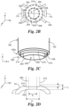
- FIGS. 2A-D illustrate an example dissection system 10 for manually removing corneal tissue.
- the dissection system 10 includes a housing 100, a blade assembly 200, and a syringe 300.
- the housing 100 has a contact side 100a that can be placed against the cornea 2.
- the contact side 100a may be contoured to accommodate the general anterior shape of the cornea 2.
- the housing 100 includes a substantially cylindrical outer wall 102 that extends upwardly from the contact side 100a (in the positive-z direction).
- the housing 100 includes an interior passageway 108 with an opening 110 at the contact side 100a.
- the housing 100 includes one or more vacuum chambers 104 that can be coupled to the syringe 300 or other negative pressure source via a tube 302. (The vacuum chambers 104 are selectively shown in FIG. 2A with dashed lines.) The plunger of the syringe 300 may be drawn back or otherwise operated to provide a negative pressure in the vacuum chambers 104 via the tube 302.
- One or more vacuum openings 106 for the vacuum chambers 104 are arranged along the periphery of the opening 110 at the contact side 100a. The vacuum openings 106 can engage the epithelial surface 2c of the cornea 10.
- Negative pressure in the vacuum chambers 104 generates suction between the epithelial surface 2c and the housing 100 at the vacuum openings 106, thereby securely fixing the housing 100 to the cornea 2.
- the syringe 300 can be operated in an opposite manner to create positive pressure in the vacuum chambers 104 and release the suction at the vacuum openings 106.
- the housing 100 includes positioning elements 110 that extend radially outward from the outer wall 102.
- the positioning elements 110 provide sufficient surface area that the practitioner can use to hold and position the housing 100, e.g., between his/her fingers.
- the blade assembly 200 is disposed in the interior passageway 108 of the housing 100.
- the blade assembly 200 includes a manipulator 202, which can be operated to cut the cornea 2 with the blade assembly 200.
- a threaded coupling may be provided between the housing 100 and the blade assembly 200.
- the manipulator 202 may be rotated about the z-axis to cause rotation of the blade assembly 200 relative to the housing 100.
- the blade assembly 200 also rides along the thread of the coupling, which thus causes the blade assembly 200 to move axially (along the z-axis) relative to the housing 100 and the cornea 2. As shown in the top view of FIG.
- the manipulator 202 includes a plurality of radially extending rods 204 which the practitioner can use to rotate the manipulator 202, e.g., with his/her fingers. The practitioner may simultaneously use the positioning elements 110 to hold the housing 100 stably in position while rotating the manipulator 202.
- the manipulator 202 can move the blade assembly 200 in the negative-z direction and through the passageway opening 110 until the blade assembly 200 penetrates the cornea 2 positioned against the contact side 100a of the housing 100.
- the housing 100 is securely coupled to the cornea 2 so that the blade assembly 200 is restricted to predictable and precise movement along the z-axis into the cornea 2.
- the blade assembly 200 includes an outer blade 210 and an inner blade 220.
- the outer blade 210 and the inner blade 220 are selectively shown in FIGS. 2A , C with dashed lines.
- the outer blade 210 and the inner blade 220 are substantially tubular.
- the outer blade 210 includes a central passageway 212 with a substantially circular cutting edge 214.
- the inner blade 220 is disposed in the central passageway 212 of the outer blade 210 and extends past the cutting edge 214 of the outer blade 210.
- the inner blade 220 also includes a central passageway 222 with a substantially circular cutting edge 224.
- the outer cutting edge 214 and the inner cutting edge 224 are substantially concentric.
- the outer blade 210 and the inner blade 220 create substantially concentric circular cuts into the cornea 2.
- the circular cut made by the outer cutting edge 214 has a larger diameter than the circular cut made by the inner cutting edge 224.
- the outer cutting edge 214 may have a diameter that makes a substantially circular outer cut with the first diameter di, which corresponds to the anterior portion 2a removed from the cornea 2.
- the inner cutting edge 224 may have a diameter that makes a substantially circular inner cut with the second diameter d 2 , which corresponds to the posterior portion 2b removed from the cornea 2.
- the manipulator 202 moves the outer blade 210 and the inner blade 220 simultaneously.
- the manipulator 202 includes an aperture 206 that aligns with the central passageway 222 of the inner blade 220.
- the cornea 2 can be seen through the aperture 206 and the central passageway 222.
- Cross-hairs 208 or other positioning guides may be disposed in the aperture 206 and/or the central passageway 222 to mark the center of the outer blade 210 and the inner blade 220.
- the practitioner may employ the cross-hairs 208 to fix the housing 100 to the cornea 2 and center the blades 210, 220 over a desired location, e.g., the center, of the cornea 2.
- the location of the cuts made by the outer cutting edge 214 and the inner cutting edge 224 can be controlled.
- the inner blade 220 extends farther downward in the negative-z direction than the outer blade 210.
- the blade assembly 200 includes an outer blade depth controller 216 to control the penetration depth of the outer blade 210 and an inner blade depth controller 226 to control the penetration depth of the inner blade 220.
- the outer blade depth controller 215 and the inner blade depth controller 226 may be separately rotated about the z-axis as manual dials to set the respective penetration depths.
- the outer blade depth controller 216 may be operated so that the outer blade 210 moves past the contact side 100a of the housing 100 by a distance that makes an outer cut in the cornea 2 with a depth of t 1 . This provides the first thickness ti of the anterior portion 2a. Additionally, the inner blade depth controller 226 may be operated so that the inner blade 220 moves past the contact side 100a of the housing 100 by a distance that makes an inner cut in the cornea 2 with a depth of t 1 + t 2 . This provides the second thickness t 2 of the posterior portion 2b.
- the outer blade depth controller 216 can move one or more adjustable stops 112 to a position along the interior passageway 108 of the housing 100.
- One or more corresponding stops 218 are coupled to the outer blade 210.
- the stops 112, 218 are selectively illustrated by dashed lines in FIG. 2A .
- the outer blade depth controller 216 may provide numerical markers to allow the practitioner to dial a position for the stops 112 corresponding to the desired penetration depth t 1 for the outer blade 210.
- the inner blade depth controller 226 can adjust the distance between the inner cutting edge 224 and the outer cutting edge 214.
- the inner blade 220 may be adjustably coupled to the outer blade 210, e.g., by a threaded coupling, and the inner blade depth controller 226 may be operated to adjust the coupling and set the distance.
- the inner blade depth controller 226 may provide numerical markers to allow the practitioner to dial the desired thickness t 2 for the posterior portion 2b. This thickness is equivalent to the distance between the cutting edges 214, 224.
- the manipulator 202 may be operated to move the outer blade 210 as described above.
- the inner blade 220 moves with the outer blade 210 at the set distance.
- the outer blade 210 creates an outer cut with the depth and diameter to remove the anterior portion 2a
- the inner blade 220 creates an inner cut with the depth and smaller diameter to remove the posterior portion 2b. (The inner cut of the inner blade 220 also passes through the anterior portion 2a but does not affect the outer cut of the outer blade 210.)
- the housing 100 and the blade assembly 200 can be released from die cornea 2 by operation of the manipulator 202 and the syringe 300.
- a separate dissection device or other manual instrument may be employed to remove the anterior portion 2a and the posterior portion 2b.
- an annular cut is made at substantially the penetration depth of t 1 for the outer blade, between the outer cut to the inner cut.
- a circular cut defined by the circumference of the inner cut is made at substantially the penetration depth of t 1 + t 2 for the inner blade.
- the removal of the portions 2a, b produces a bed 2f for receiving the corneal implant 4. With the precision of the cuts by the dissection system 10, the bed 2f provides a dimensional match with the corneal implant 4.
- FIG. 3 illustrates another example dissection system 20 including an alternative blade assembly 400 with an outer blade 410 and an inner blade 420.
- the movement of the inner blade 420 is not coupled to the movement of the outer blade 410.
- the blade assembly 400 includes a first manipulator 402a to move the outer blade 410 along the z-axis and a second manipulator 402b to move the inner blade 420 separately along the z-axis.
- the blade assembly 400 includes an outer blade depth controller 416 that can move one or more adjustable stops 432 to a position along the interior passageway 108 of the housing 100 One or more corresponding stops 418 are coupled to the outer blade 410. Similar to the manipulator 202, when the manipulator 402a is operated, the outer blade 410 can move downward in the negative-z direction and penetrate the cornea 2 until the stops 418 of the outer blade 410 reach the stops 432 at the set position.
- the outer blade depth controller 416 may provide numerical markers to allow the practitioner to dial a position for the stops 432 corresponding to the desired penetration depth t 1 for the outer blade 410.
- the blade assembly 400 includes an inner blade depth controller 426 that that can move one or more adjustable stops 442 to a position along a central passageway 112 of the outer blade 410 One or more corresponding stops 428 are coupled to the inner blade 420
- the inner blade 420 can move in the negative-z direction and penetrate the cornea 2 until the stops 428 of the inner blade 420 reach the stops 442 at the set position.
- the inner blade depth controller 426 may provide numerical markers to allow the practitioner to dial a position for the stops 442 corresponding to the desired penetration depth t 1 + t 2 for the inner blade 420. Accordingly, the practitioner operates each of the manipulators 402a, b separately to make the respective outer and inner cuts.
- FIG. 4 illustrates another example dissection system 30 including an alternative blade assembly 500 as well as the housing 100 and the syringe 300.
- the blade assembly 500 includes an outer blade 510 and an inner blade 520 with constant respective penetration depths.
- blade assembly 500 does not employ depth controllers that allow the respective penetration depths to be adjusted.
- one or more stops 532 are fixedly positioned along the interior passageway 108 of the housing 100.
- One or more corresponding stops 518 are coupled to the outer blade 510.
- the blade assembly 500 includes a manipulator 502 that can be operated to move the outer blade 510 in the negative-z direction and penetrate the cornea 2 until the stops 518 of the outer blade 510 reach the stops 532 at the set position.
- the position for the stops 532 corresponds to the desired penetration depth t 1 for the outer blade 5 10.
- the inner blade 520 has an inner cutting edge 524 that is fixedly positioned at a distance t 2 from an outer cutting edge 514 of the outer blade 510. As such, when the outer blade 510 reaches the desired penetration depth t 1 , the inner blade 520 reaches a desired penetration depth t 1 + t 2 . Accordingly, the practitioner operates the manipulator 502 to make the same outer and inner cuts.
- a separate dissection device or other manual instrument may be employed to remove the anterior portion 2a and the posterior portion 2b after a blade assembly 200, 400, 500 has been manipulated to make cuts in the cornea with the outer blade and the inner blade.
- the blade assembly may be configured to make further cuts to remove the anterior portion 2a and the posterior portion 2b.
- Such a blade assembly eliminates the need for a separate dissection device or other manual instrument.
- the blade assembly can make a cut (e.g., an annular cut) at the penetration depth of ti, between the outer cut to the inner cut.
- the blade assembly can make a cut (e.g., a circular cut) defined by the inner cut at the penetration depth of t 1 + t 2 .
- the annular and circular cuts are generally transverse to the outer and inner cuts, respectively.
- FIGS. 5A-C illustrate an example dissection system 40 employing a blade assembly 600.
- the blade assembly 600 includes an outer blade 610 and an inner blade 620 with constant respective penetration depths.
- the inner blade 620 has an inner cutting edge 624 that is fixedly positioned at a distance t 2 from an outer cutting edge 614 of the outer blade 610. As such, when the outer blade 610 reaches the desired penetration depth t 1 , the inner blade 620 reaches a desired penetration depth t 1 + t 2 .
- the dissection system 40 includes the housing 100 and the syringe 300. As described above, the housing 100 can be positioned securely against the cornea 2 with the use of a negative pressure provided by the syringe 300.
- the blade assembly 600 is disposed in the interior passageway 108 of the housing 100. The housing 100 thus positions the blade assembly 600 relative to the cornea. 2.
- the blade assembly 600 includes a manipulator 602 that can be rotated about the z-axis to cause the outer blade 610 to move relative to the housing 100 and the cornea 2. Such movement of the outer blade 610 results in corresponding movement of the inner blade 620, which is fixed relative to the outer blade 610.
- the manipulator 602 can be rotated to cause penetration of the outer blade 610 to a desired depth t 1 and penetration of the inner blade 620 to a desired depth t 1 + t 2 .
- the manipulator 602 includes a plurality of radially extending rods 604 which the practitioner can use to rotate the manipulator 602, e.g., with his/her fingers. The practitioner may simultaneously use the positioning elements 110 to hold the housing 100 stably in position while rotating the manipulator 602.
- the blade assembly 600 can make an annular cut at the penetration depth t 1 between the cuts made by the outer blade 610 and the inner blade 620. Additionally, at the penetration depth t 1 + t 2, the blade assembly 600 can make a circular cut with a circumference defined by the inner blade 620. Together, the annular cut and the circular cut allow the anterior portion 2a and the posterior portion 2b to be removed.
- the blade assembly 600 includes wires 651 (or similar cutting structures) that extend between the outer blade 610 and the inner blade 620 within the central passageway 612 of the outer blade 610.
- the wires 651 are aligned with the outer cutting edge 614 of the outer blade 610 (i.e., generally, at the same position on the z-axis as the outer cutting edge 614).
- the blade assembly 600 includes a wire 652 (or similar cutting structure) that extends across the central passageway 222 of the inner blade 620.
- the wire 652 is aligned with the inner cutting edge 612 of the inner blade 610 (i.e., generally, at the same position on the z-axis as the inner cutting edge 612).
- the wires 651 When the outer cutting edge 614 of the outer blade 610 penetrates the cornea 2 to the desired depth t 1 , the wires 651 also penetrate the cornea 2 to the desired depth t 1 . Meanwhile, when the inner cutting edge 624 of the inner blade 620 correspondingly penetrates the cornea 2 to the desired depth t 1 + t 2 , the wire 652 also penetrates the cornea to the desired depth t 1 + t 2 .
- the wires 651, 652 have sufficient tension and sharpness to cut through the cornea 2 and do not generate significant resistance against the movement of the outer blade 610 and the inner blade 610.
- FIGS. 5B-C illustrate two wires 651 and one wire 652 as an example, embodiments may employ different numbers of wires 651 and/or wires 652.
- the wires 651, 652 can penetrate the cornea 2, because the outer blade 610 and the inner blade 620 do not rotate relative to the housing 100 and the cornea 2 when penetrating the cornea 2.
- FIG. 5D illustrates an example configuration for coupling the manipulator 602 to the outer blade 610 and the inner blade 620.
- the example configuration allows the manipulator 602 to be operated so that the outer blade 610 and the inner blade 620 move axially along the z-axis to penetrate the cornea 2 without rotating about the z-axis.
- the manipulator 602 is coupled to the housing 100.
- the manipulator 602 can rotate about the z-axis relative to the housing 100, but cannot move according to other degrees of freedom relative to the housing 100.
- the manipulator 602 may include engagement structures 605 that can snap into an annular track 105 running along a surface (e.g., top surface) of the housing 100; the engagement structures 605 can move within the annular track 105 to allow rotation of the manipulator 602.
- the manipulator 602 includes a central passageway 603.
- the outer blade 610 is disposed within the central passageway 603.
- the outer blade 610 includes an outer surface 617 that faces an inner surface 607 of the manipulator 602 within the central passageway 603.
- the manipulator 602 includes a thread 662 that spirals along the inner surface 607.
- the outer blade 610 includes tabs 664 that are biased to extend radially outward from the outer surface 617 and engage the thread 662. When the manipulator 602 is rotated in a first direction about the z-axis, the thread 662 applies a force against the tabs 664 in the negative-z direction.
- This force causes the outer blade 610, as well as the inner blade 620 fixed to the outer blade 610, to move in the negative-z direction and penetrate the cornea 2.
- the movement of the outer blade 610 and the inner blade 620 does not involve rotation about the z-axis relative to the housing 100 and the cornea 2.
- the housing 100 may include one or more guide structures to engage the outer blade 610 and prevent such rotation while allowing movement along the z-axis. Rotation of the manipulator 602 in the first direction stops when the outer blade 610 and the inner blade 620 reach their respective desired penetration depths t 1 and t 1 + t 2 , respectively.
- the manipulator 602 can be further operated to make additional cuts (e.g., transverse cuts) to allow the anterior portion 2a and the posterior portion 2b to be removed.
- the manipulator 602 can be rotated in a second direction about the z-axis to cause the wires 651, 652 to rotate about the z-axis. This second direction is opposite from the first direction in which the manipulator 602 is rotated to move the outer blade 610 and the inner blade 620 in the negative-z direction.
- Rotation of the wires 651 makes an annular cut at the penetration depth t 1 , between the outer cut to the inner cut.
- rotation of the wire 652 makes a circular cut at the penetration depth of t 1 + t 2 .
- the outer blade 610 and the inner blade 620 do not move in the positive-z direction.
- the thread 662 may apply a force against the tabs 664 in the positive-z direction
- the tabs 664 are shaped (e.g., with an angled surface) so that such force also pushes the tabs 664 radially inward.
- the force overcomes the radially outward bias of the tabs 664, causing the tabs to move radially inward. This inward movement of the tabs 664 prevents the force in the positive-z direction from pushing the outer blade 610 and the inner blade 620 in the positive-z direction.
- the manipulator 602 includes tabs 663 that engage the tabs 664 of the outer blade 610 as the manipulator is rotated in the second direction.
- the engagement between the tabs 663, 664 causes the outer blade 610 as well as the inner blade 620 to rotate in the second direction with the manipulator 602.
- the wires 651, 652 rotate correspondingly with the outer blade 610 and inner blade 620. Because the thread 662 does not move the outer blade 610 and inner blade 620 along the z-axis, the wires 651, 652 rotate on the x-y planes at the depths t 1 and t 1 + t 2 , respectively, to produce the desired cuts.
- the anterior portion 2a and the posterior portion 2b can be removed from the cornea 2. In some cases, withdrawal of the dissection system 40 from the cornea 2 also removes the dissected tissue.
- each tab 664 is disposed on one end of a biasing structure 666 positioned within the outer blade 610.
- the biasing structure 666 pushes the tabs 664 radially outward through the outer surface 617 of the outer blade 610.
- a button 668 is disposed near the other end of the biasing structure 666 and also extends radially outward through the outer surface 617. When the button 668 is pushed radially inward, resulting movement of the biasing structure 666 causes the tab 664 to also move radially inward and to disengage the track 662 of the manipulator 602. Accordingly, the buttons 668 can be squeezed together with fingers to allow the outer blade 610, as well as the inner blade 620, to be moved in the positive-z direction, back to a starting position for the subsequent dissection procedure.
- FIG. 5E illustrates an alternative configuration for coupling the manipulator 602 to the outer blade 610 and the inner blade 620. Similar to the configuration of FIG. 5D , the manipulator 602 is coupled to the housing 100 (not shown). The manipulator 602 can rotate about the z-axis relative to the housing 100, but cannot move according to other degrees of freedom relative to the housing 100. In addition, the manipulator 602 includes the central passageway 603. The outer blade 610 is disposed within the central passageway 603. The outer surface 617 of the outer blade 610 faces the inner surface 607 of the manipulator 602.
- the manipulator 602 includes the thread 662 which spirals along the inner surface 607.
- the outer blade 610 includes tabs 674 that are biased to extend radially outward from the outer surface 617 and engage the threads 672.
- the thread 672 applies a force against the tabs 674 in the negative-z direction.
- This force causes the outer blade 610, as well as the inner blade 620 fixed to the outer blade 610, to move in the negative-z direction and penetrate the cornea 2.
- the movement of the outer blade 610 and the inner blade 620 does not involve rotation about the z-axis relative to the housing 100 and the cornea 2.
- the housing 100 may include one or more guide structures to engage the outer blade 610 and prevent such rotation while allowing movement along the z-axis.
- the tabs 674 continue to move along the thread 672 until they enter a groove 676 at the end of the thread 672. At this point, the outer blade 610 and the inner blade 620 have reached their desired penetration depths t 1 and t 1 + t 2 , respectively. With the tabs 674 positioned in the groove 676, the thread 672 can no longer apply a force to the tabs 674 and the manipulator 602 can be further rotated in the same first direction about the z-axis to make additional cuts to allow the anterior portion 2a and the posterior portion 2b to be removed.
- the manipulator 602 includes tabs 673 that engage the tabs 664 of the outer blade 610 as the manipulator continues to rotate in the first direction.
- the engagement between the tabs 663, 664 causes the outer blade 610 as well as the inner blade 620 to rotate in the first direction with the manipulator 602.
- the wires 651, 652 rotate correspondingly with the outer blade 610 and inner blade 620. Because the thread 672 does not move the outer blade 610 and inner blade 620 along the z-axis, the wires 651, 652 rotate on the x-y planes at the depths t 1 and t 1 + t 2 , respectively, to produce the desired cuts. As described above, rotation of the wires 651 makes an annular cut at the penetration depth t 1 , between the outer cut to the inner cut. Meanwhile, rotation of the wire 652 makes a circular cut at the penetration depth of t 1 + t2.
- each tab 674 is disposed on one end of the biasing structure 666 positioned within the outer blade 610.
- the biasing structure 666 pushes the tabs 674 radially outward through the outer surface 617 of the outer blade 610.
- a button 668 is disposed near the other end of the biasing structure 666 and also extends radially outward through the outer surface 617. When the button 668 is pushed radially inward, resulting movement of the biasing structure 666 causes the tab 674 to also move radially inward and allows the tab 674 to disengage the track 672 of the manipulator 602. Accordingly, the buttons 668 can be squeezed together with fingers to allow the outer blade 610, as well as the inner blade 620, to be moved in the positive-z direction, back to a starting position for the subsequent dissection procedure.
- the wires 651, 652 in the example dissection system 40 have sufficient tension and sharpness to cut through die cornea 2 as the outer blade 610 and the inner blade 620 penetrate the cornea 2.
- Operation of the manipulator 602 to rotate the wires 651, 652 can also increase the tension in the wires 651, 652.
- Alternative embodiments, however, may provide additional support for the movement of the wires 651, 652 in the negative-z direction.
- FIGS. 6A-B illustrates the outer blade 610 and the inner blade 620, as well as the wires 651, 652 described above.
- FIG. 6A shows a support structure 653 extending between the outer blade 610 and the inner blade 620 and to the cutting edge 614 of the outer blade 610.
- One of the wires 651 is disposed at the end of the support structure 653 and aligned with the cutting edge 614.
- the end of the support structure 653 may be recessed or otherwise shaped to engage the wire 651 further.
- An additional support structure 653 (not shown) may be implemented with the other wire 651.
- FIG. 6B shows a support structure 655 extending to the cutting edge 624 within the central passageway 622 of the inner blade 620.
- the wire 652 is disposed at the end of the support structure 655 and aligned with the cutting edge 624.
- the end of the support structure 655 may be recessed or otherwise shaped to engage the wire 652 further.
- the support structures 653, 655 move with the outer blade 610 and the inner blade 620 as they penetrate the cornea 2.
- the support structures 653, 655 help the wires 651, 652 to move through the cornea 2.
- the manipulator 602 may be operated as described above to make the additional cuts with the wires 651, 652.
- the wires 651, 652 disengage from the respective support structures 653, 655 to rotate with the manipulator 602.
- the support structures 653, 655 may have a wedge-like or blade-like shapes extending substantially along the length of the outer blade 610 and the inner blade 620, respectively. In other embodiments, however, the support structures 653, 655 may have alternative shapes. For instance, the support structures 653, 655 may be shorter cross-bars that extend across and above the wires 651, 655 to provide support.
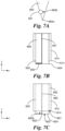
- FIGS. 7A-C illustrate an alternative approach for supporting for the movement of the wires in the negative-z direction.
- FIG. 7A illustrates a support structure 683 for a wire 651.
- a single wire 651 is employed here.
- the end 683a of the support structure 683 provides a leading edge as the outer blade 610 and the inner blade 620 penetrate the cornea 2.
- the support structure 683 includes a recess 683b that receives the wire 651 above the end 683a of the support structure 683.
- the wire 651 in FIGS. 6A-C is positioned below the support structure 653 and provides the leading edge.
- the end 683a may be sharper than the wire 651 and can cut through the cornea 2 more easily while the wire 251 remains in the recess 683b.
- the manipulator 602 may be operated to disengage the wire 651 from the recess 683b in the support structure 683 and to rotate the wire 651 about the z-axis to produce the cuts to help remove the anterior portion 2a.
- the support structure 683 delivers the wire 651 to a depth where the wire 251 can provide an effective cut near the penetration depth t 1 (e.g., within approximately 5 ⁇ m).
- a wire 652' as shown in the views of FIGS. 7B-C may be employed.
- the support structure 685 for the wire 652' may be configured to receive the wire 652' in a recess 685b in a manner similar to the support structure 683.
- the wire 652' extends across the radius of the inner blade 620.
- the wire 652' extends from a center support 657 to an inner wall of the inner blade 620. The wire 652' can rotate about the center support 657 to make the desired circular cut.
- die rotation of the wires 651, 652' starts from one side of the support structures 683, 685 (i.e., out of the recesses 683b, 685b) and ends on the other side of the support structures 683, 685, respectively.
- the wires 651, 652' are blocked by the support structures 683, 685 from making complete annular and circular cuts, respectively.
- the cuts by the wires 651, 652' are sufficient to allow removal of the anterior portion 2a and posterior portion 2b, respectively.
- the inner and outer blades of the example embodiments above may have substantially circular profiles, it is understood that the other embodiments may employ other profiles to make cuts of different shapes, e.g., elliptical cuts. Additionally, it is understood that the blade assemblies in other embodiments may be configured to make non-concentric inner and outer cuts. Furthermore, it is understood that the blade assemblies in other embodiments may include more than two blades.
- the inner cuts made by the inner blade in the example implementations above may have penetration depths that extend through the endothelium, it is understood that other implementations may employ penetration depths that do not extend completely to the endothelium.
- the blade assemblies of the example embodiments above may remove a volume of corneal tissue having a mushroom shape, it is contemplated that blade assemblies in other embodiments may be configured to make cuts that allow corneal tissue to be removed according to other shapes.
Landscapes
- Health & Medical Sciences (AREA)
- Engineering & Computer Science (AREA)
- Ophthalmology & Optometry (AREA)
- Biomedical Technology (AREA)
- Vascular Medicine (AREA)
- Public Health (AREA)
- Veterinary Medicine (AREA)
- Heart & Thoracic Surgery (AREA)
- Transplantation (AREA)
- Life Sciences & Earth Sciences (AREA)
- Animal Behavior & Ethology (AREA)
- General Health & Medical Sciences (AREA)
- Cardiology (AREA)
- Oral & Maxillofacial Surgery (AREA)
- Nuclear Medicine, Radiotherapy & Molecular Imaging (AREA)
- Surgery (AREA)
- Surgical Instruments (AREA)
- Prostheses (AREA)
Description
- The present disclosure pertains to systems and methods for transplanting a cornea to treat disorders of the eye, and more particularly, to systems and methods for dissecting tissue for corneal transplants.
- Various disorders of the eye may result from diseased/damaged corneal tissue. The diseased/damaged comeal tissue can affect vision by scattering and/or distorting light and causing glare and/or blurred vision. In some cases, proper vision can only be restored by a corneal transplant which replaces the diseased/damaged corneal tissue with healthy tissue from an organ donor. The document
US 5 938 674 A discloses a dissection device for corneal transplants according to the preamble of claim 1. - The present invention is defined in claim 1 and the dependent claims. Systems and methods of the present disclosure employ a manual dissection system to remove diseased/damaged tissue from a cornea according to dimensions that match a corneal implant. For instance, to minimize the removal of the endothelium in a full-thickness transplant, the manual dissection system may remove a volume of diseased/damaged tissue according to a mushroom shape.
- According to an example embodiment, a dissection system for corneal transplants includes a housing including a contact side configured to be positioned against a cornea. The housing includes an interior passageway with an opening at the contact side. The dissection system includes a blade assembly disposed in the interior passageway of the housing. The blade assembly includes a first blade and a second blade. The first blade includes a first cutting edge and the second blade includes a second cutting edge. The first blade and the second blade are movable relative to the housing such that the first cutting edge and the second cutting edge extend through the opening of the housing and out of the interior passageway. The first cutting edge is configured to produce a first cut in the cornea disposed at the contact side and the second cutting edge is configured to produce a second cut in the cornea. The first cut and the second cut defines a volume of tissue for removal from the cornea. The dissection system includes one or more manipulators configured to move the first blade and the second blade relative to the housing. The system may further include one or more cutting mechanisms configured to make further cuts transverse to at least one of the first cut or the second cut. The one or more cutting mechanisms may include one or more wires, and the one or more manipulators may be configured to move the wires to make the transverse cuts.
- According to another example embodiment, a method operates a dissection system for corneal transplants. The dissection system includes a housing including a contact side configured to be positioned against a cornea, the housing including an interior passageway with an opening at the contact side. The dissection system includes a blade assembly disposed in the interior passageway of the housing. The blade assembly includes a first blade and a second blade, the first blade including a first cutting edge, the second blade including a second cutting edge, and the first blade and the second blade being movable relative to the housing. The dissection system includes one or more manipulators. The method includes positioning the contact side of the housing against a cornea. The method includes operating the one or more manipulators to move the first blade and the second blade relative to the housing such that the first cutting edge and the second cutting edge extend past the opening of the housing and out of the interior passageway. The first cutting edge produces a first cut in the cornea disposed at the contact side and the second cutting edge produces a second cut in the cornea, the first cut and the second cut defining a volume of tissue for removal from the cornea. The method may further include making further cuts, with one or more cutting mechanisms, transverse to at least one of the first cut or the second cut. The one or more cutting mechanisms may include one or more wires, and the method may further comprise operating the one or more manipulators to move the wires to make the transverse cuts.
-
-
FIG. 1 illustrates example removal of tissue from a cornea according to a mushroom shape and a correspondingly shaped corneal implant received by a bed in the cornea formed by the removal of the tissue. -
FIG. 2A illustrates an example dissection system for precise manual removal of corneal tissue in a corneal implant, according to aspects of the present disclosure. -
FIG. 2B illustrates a top view of the example dissection system ofFIG. 2A . -
FIG. 2C illustrates a partial perspective view of the example dissection system ofFIG. 2A . -
FIG. 2D illustrates an example implementation of the example dissection system ofFIG. 2A . -
FIG. 3 illustrates another example dissection system for precise manual removal of corneal tissue in a corneal implant, according to aspects of the present disclosure. -
FIG. 4 illustrates yet another example dissection system for precise manual removal of corneal tissue in a corneal implant, according to aspects of the present disclosure. -
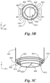
FIG. 5A illustrates a further example dissection system for precise manual removal of corneal tissue in a corneal implant, including an additional cutting mechanism for making cuts after penetration of outer/inner blades into the cornea, according to aspects of the present disclosure. -
FIG. 5B illustrates a bottom view of the example dissection system ofFIG. 5A . -
FIG. 5C illustrates a partial perspective view of the example dissection system ofFIG. 5A . -
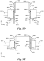
FIG. 5D illustrates an example coupling between a manipulator and the outer/inner blades for the example dissection system ofFIG. 5A . -
FIG. 5E illustrates another example coupling between a manipulator and the outer/inner blades for the example dissection system ofFIG. 5A . -
FIG. 6A illustrates aspects of an alternative cutting mechanism for making cuts after penetration of outer/inner blades into the cornea with a dissection system, according to aspects of the present disclosure. -
FIG. 6B illustrates further aspects of the alternative cutting mechanism ofFIG. 6A . -
FIG. 7A illustrates aspects of an alternative cutting mechanism for making cuts after penetration of outer/inner blades into the cornea with a dissection system, according to aspects of the present disclosure. -
FIG. 7B illustrates a cross-sectional view of further aspects of the alternative cutting mechanism ofFIG. 7A . -
FIG. 7C illustrates yet further aspects of the alternative cutting mechanism ofFIG. 7A . - Various disorders of the eye may result from diseased/damaged corneal tissue. The diseased/damaged corneal tissue can affect vision by scattering and/or distorting light and causing glare and/or blurred vision. In some cases, proper vision can only be restored by a corneal transplant which replaces the diseased/damaged corneal tissue with healthy tissue from an organ donor.
- From the outer (anterior) surface of the eye to the inner (posterior) parts, the structure of the cornea includes five layers: (1) epithelium, (2) Bownian's layer, (3) stroma, (4) Descemet's membrane, and (5) endothelium. Penetrating keratoplasty (PK) involves a full-thickness transplant where all layers of the cornea from the epithelium to the endothelium are removed and replaced with a corneal implant. In PK, a manual dissection device known as a trephine may be employed to remove the full thickness of existing corneal tissue. The trephine may also be used to cut a donor cornea to provide the corneal implant that dimensionally matches the removed corneal tissue. The corneal implant is then positioned in place of the removed corneal tissue and sutured into place.
- Anterior lamellar keratoplasty (ALK) is an alternative treatment that selectively replaces diseased/damaged tissue in an anterior part of the cornea. A type of ALK procedure is deep anterior lamellar keratoplasty (DALK) which removes the epithelium, Bowman's layer, and the stroma but leaves the native Descemet's membrane and endothelium in place. In ALK, the surgeon dissects the cornea and removes the anterior part of the cornea. A dimensionally matching corneal implant from a donor cornea is then positioned in a bed formed by the removal of corneal tissue and sutured into place.
- ALK is less invasive than PK and is preferred when the endothelium is healthy. In contrast to the cells of the epithelium and the stroma, the cells of the endothelium cannot regenerate. With ALK, patients retain their own endothelium so the risk of rejection by the immune system may be dramatically reduced.
- Although PK involves a full-thickness transplant, certain approaches for PK attempt to minimize the removal of the endothelium. For instance, a patient may have a healthy endothelium, but central corneal scars and full-thickness opacities require a full-thickness transplant. As shown in
FIG. 1 , an example approach for PK removes ananterior portion 2a and aposterior portion 2b of tissue from acornea 2. The approach illustrated inFIG. 1 can provide more effective and faster healing. Theanterior portion 2a extends from theepithelial surface 2c of thecornea 2 to a depth in thestroma 2d to define a first thickness t1 (along the z-axis as shown). Theanterior portion 2a has a substantially circular profile along the x-y plane with a first diameter di. For instance, the first thickness ti may be approximately 175 µm to approximately 200 µm and the first diameter d1 may be approximately 9 mm. Theposterior portion 2b extends from theanterior portion 2a through theendothelium 2;, to define a second thickness t2. (along the z-axis). t1 + t2 is the thickness from theepithelial surface 2c through the endothelium. Theposterior portion 2b has a substantially circular profile along the x-y plane with a second diameter d2. For instance, the second thickness t2 may be approximately 350 µm and the second diameter d2 may be approximately 6.5 mm (or larger). The first diameter d1 of theanterior portion 2a is greater than the second diameter d2 of theposterior portion 2b. The difference between the first diameter d1 and the second diameter d2 may be approximately 0.5 mm to approximately 1 mm. As such, theportions 2a, b together define a volume of tissue having a mushroom shape. The removal of theposterior portion 2b results in the removal of a smaller section of the endothelium than would be the case if theposterior portion 2b were to have the same diameter d1 as theanterior portion 2a (corresponding to a removal of corneal tissue having a uniform diameter d1). - As also shown in
FIG. 1 , the removal of theportions 2a, b forms abed 2f in thecornea 10. Thebed 2f also has a mushroom shape. Acorneal implant 4 is correspondingly shaped to be received in thebed 2f. Using a microkeratome or other conventional dissection device to manually remove theportions 2a, b may not provide die sufficient precision to ensure a dimensional match between thecorneal implant 4 and thebed 2f. Indeed, the mushroom shape of thecorneal implant 4 and thebed 2f makes it a greater challenge to achieve a match. Although a femtosecond laser may be employed to cut theportions 2a, b precisely from thecornea 2, practitioners might not be conveniently equipped with a femtosecond laser system to cut thecornea 2 according to matching dimensions. - Advantageously, aspects of the present disclosure provide approaches for manually removing corneal tissue with the precision and consistency necessary to match the dimensions of a corneal implant. Such approaches employ devices that are more convenient and cost-effective than a femtosecond laser. With such devices, it is feasible for suppliers to shape a corneal implant with a femtosecond laser or similar high-precision cutting system and for practitioners to remove a volume of tissue manually and form a bed that accurately matches the shape of the corneal implant provided by the supplier.
-
FIGS. 2A-D illustrate anexample dissection system 10 for manually removing corneal tissue. As shown inFIG. 2A , thedissection system 10 includes ahousing 100, ablade assembly 200, and asyringe 300. Thehousing 100 has acontact side 100a that can be placed against thecornea 2. Thecontact side 100a may be contoured to accommodate the general anterior shape of thecornea 2. Thehousing 100 includes a substantially cylindricalouter wall 102 that extends upwardly from thecontact side 100a (in the positive-z direction). Thehousing 100 includes aninterior passageway 108 with anopening 110 at thecontact side 100a. - The
housing 100 includes one ormore vacuum chambers 104 that can be coupled to thesyringe 300 or other negative pressure source via atube 302. (Thevacuum chambers 104 are selectively shown inFIG. 2A with dashed lines.) The plunger of thesyringe 300 may be drawn back or otherwise operated to provide a negative pressure in thevacuum chambers 104 via thetube 302. One ormore vacuum openings 106 for thevacuum chambers 104 are arranged along the periphery of theopening 110 at thecontact side 100a. Thevacuum openings 106 can engage theepithelial surface 2c of thecornea 10. Negative pressure in thevacuum chambers 104 generates suction between theepithelial surface 2c and thehousing 100 at thevacuum openings 106, thereby securely fixing thehousing 100 to thecornea 2. To decouple thehousing 100 from thecornea 2, thesyringe 300 can be operated in an opposite manner to create positive pressure in thevacuum chambers 104 and release the suction at thevacuum openings 106. - The
housing 100 includespositioning elements 110 that extend radially outward from theouter wall 102. Thepositioning elements 110 provide sufficient surface area that the practitioner can use to hold and position thehousing 100, e.g., between his/her fingers. - The
blade assembly 200 is disposed in theinterior passageway 108 of thehousing 100. Theblade assembly 200 includes amanipulator 202, which can be operated to cut thecornea 2 with theblade assembly 200. For instance, a threaded coupling may be provided between thehousing 100 and theblade assembly 200. Themanipulator 202 may be rotated about the z-axis to cause rotation of theblade assembly 200 relative to thehousing 100. As it rotates, theblade assembly 200 also rides along the thread of the coupling, which thus causes theblade assembly 200 to move axially (along the z-axis) relative to thehousing 100 and thecornea 2. As shown in the top view ofFIG. 2B , themanipulator 202 includes a plurality of radially extendingrods 204 which the practitioner can use to rotate themanipulator 202, e.g., with his/her fingers. The practitioner may simultaneously use thepositioning elements 110 to hold thehousing 100 stably in position while rotating themanipulator 202. - Accordingly, the
manipulator 202 can move theblade assembly 200 in the negative-z direction and through thepassageway opening 110 until theblade assembly 200 penetrates thecornea 2 positioned against thecontact side 100a of thehousing 100. Thehousing 100 is securely coupled to thecornea 2 so that theblade assembly 200 is restricted to predictable and precise movement along the z-axis into thecornea 2. - The
blade assembly 200 includes anouter blade 210 and aninner blade 220. (Theouter blade 210 and theinner blade 220 are selectively shown inFIGS. 2A ,C with dashed lines.) As shown in the partial view of thedissection system 10 inFIG. 2C , theouter blade 210 and theinner blade 220 are substantially tubular. Theouter blade 210 includes acentral passageway 212 with a substantiallycircular cutting edge 214. Theinner blade 220 is disposed in thecentral passageway 212 of theouter blade 210 and extends past thecutting edge 214 of theouter blade 210. Theinner blade 220 also includes acentral passageway 222 with a substantiallycircular cutting edge 224. - The
outer cutting edge 214 and theinner cutting edge 224 are substantially concentric. Correspondingly, theouter blade 210 and theinner blade 220 create substantially concentric circular cuts into thecornea 2. When theblade assembly 200 penetrates thecornea 10, the circular cut made by theouter cutting edge 214 has a larger diameter than the circular cut made by theinner cutting edge 224. For instance, as shown inFIG. 2D , theouter cutting edge 214 may have a diameter that makes a substantially circular outer cut with the first diameter di, which corresponds to theanterior portion 2a removed from thecornea 2. Additionally, theinner cutting edge 224 may have a diameter that makes a substantially circular inner cut with the second diameter d2, which corresponds to theposterior portion 2b removed from thecornea 2. - The
manipulator 202 moves theouter blade 210 and theinner blade 220 simultaneously. As shown in the top viewFIG. 2B , themanipulator 202 includes anaperture 206 that aligns with thecentral passageway 222 of theinner blade 220. As such, thecornea 2 can be seen through theaperture 206 and thecentral passageway 222.Cross-hairs 208 or other positioning guides may be disposed in theaperture 206 and/or thecentral passageway 222 to mark the center of theouter blade 210 and theinner blade 220. The practitioner may employ the cross-hairs 208 to fix thehousing 100 to thecornea 2 and center theblades cornea 2. As such, the location of the cuts made by theouter cutting edge 214 and theinner cutting edge 224 can be controlled. - As shown in
FIG. 2C , theinner blade 220 extends farther downward in the negative-z direction than theouter blade 210. Thus, when theblade assembly 200 penetrates thecornea 10, theinner blade 220 penetrates thecornea 10 to a greater depth than theouter blade 210. Theblade assembly 200 includes an outerblade depth controller 216 to control the penetration depth of theouter blade 210 and an innerblade depth controller 226 to control the penetration depth of theinner blade 220. For instance, the outer blade depth controller 215 and the innerblade depth controller 226 may be separately rotated about the z-axis as manual dials to set the respective penetration depths. - As shown in
FIG. 2D , the outerblade depth controller 216 may be operated so that theouter blade 210 moves past thecontact side 100a of thehousing 100 by a distance that makes an outer cut in thecornea 2 with a depth of t1. This provides the first thickness ti of theanterior portion 2a. Additionally, the innerblade depth controller 226 may be operated so that theinner blade 220 moves past thecontact side 100a of thehousing 100 by a distance that makes an inner cut in thecornea 2 with a depth of t1 + t2. This provides the second thickness t2 of theposterior portion 2b. - According to an example embodiment, the outer
blade depth controller 216 can move one or moreadjustable stops 112 to a position along theinterior passageway 108 of thehousing 100. One or morecorresponding stops 218 are coupled to theouter blade 210. (Thestops FIG. 2A .) Thus, when themanipulator 202 is operated, theouter blade 210 can move downwardly in the negative-z direction and penetrate thecornea 2 until thestops 218 of theouter blade 210 reach thestops 112 at the set position. The outerblade depth controller 216 may provide numerical markers to allow the practitioner to dial a position for thestops 112 corresponding to the desired penetration depth t1 for theouter blade 210. - Meanwhile, the inner
blade depth controller 226 can adjust the distance between theinner cutting edge 224 and theouter cutting edge 214. For instance, theinner blade 220 may be adjustably coupled to theouter blade 210, e.g., by a threaded coupling, and the innerblade depth controller 226 may be operated to adjust the coupling and set the distance. The innerblade depth controller 226 may provide numerical markers to allow the practitioner to dial the desired thickness t2 for theposterior portion 2b. This thickness is equivalent to the distance between the cuttingedges - Once the distance between the cutting
edges blade depth controller 226, themanipulator 202 may be operated to move theouter blade 210 as described above. Correspondingly, theinner blade 220 moves with theouter blade 210 at the set distance. As illustrated inFIG. 2D , when theouter blade 210 is stopped from further movement by thestops 112, dieouter cutting edge 214 stops its cut at the desired penetration depth ti and theinner cutting edge 224 stops its cut at the set distance t2 from theouter cutting edge 214. Accordingly, theouter blade 210 creates an outer cut with the depth and diameter to remove theanterior portion 2a, and theinner blade 220 creates an inner cut with the depth and smaller diameter to remove theposterior portion 2b. (The inner cut of theinner blade 220 also passes through theanterior portion 2a but does not affect the outer cut of theouter blade 210.) - After making the desired outer and inner cuts, the
housing 100 and theblade assembly 200 can be released fromdie cornea 2 by operation of themanipulator 202 and thesyringe 300. With the precise outer and inner cuts, a separate dissection device or other manual instrument may be employed to remove theanterior portion 2a and theposterior portion 2b. In particular, to remove theanterior portion 2a, an annular cut is made at substantially the penetration depth of t1 for the outer blade, between the outer cut to the inner cut. Additionally, to remove theposterior portion 2b, a circular cut defined by the circumference of the inner cut is made at substantially the penetration depth of t1 + t2 for the inner blade. As described above, the removal of theportions 2a, b produces abed 2f for receiving thecorneal implant 4. With the precision of the cuts by thedissection system 10, thebed 2f provides a dimensional match with thecorneal implant 4. - Aspects of the present disclosure are not limited to the embodiment described in
FIGS. 2A-D . For instance,FIG. 3 illustrates anotherexample dissection system 20 including analternative blade assembly 400 with anouter blade 410 and aninner blade 420. In contrast to theouter blade 210 and theinner blade 220 described above, the movement of theinner blade 420 is not coupled to the movement of theouter blade 410. As such, theblade assembly 400 includes afirst manipulator 402a to move theouter blade 410 along the z-axis and asecond manipulator 402b to move theinner blade 420 separately along the z-axis. - The
blade assembly 400 includes an outerblade depth controller 416 that can move one or moreadjustable stops 432 to a position along theinterior passageway 108 of thehousing 100 One or morecorresponding stops 418 are coupled to theouter blade 410. Similar to themanipulator 202, when themanipulator 402a is operated, theouter blade 410 can move downward in the negative-z direction and penetrate thecornea 2 until thestops 418 of theouter blade 410 reach thestops 432 at the set position. The outerblade depth controller 416 may provide numerical markers to allow the practitioner to dial a position for thestops 432 corresponding to the desired penetration depth t1 for theouter blade 410. - The operation of the
manipulator 402a, however, does not move dieinner blade 420. Thus, theblade assembly 400 includes an innerblade depth controller 426 that that can move one or moreadjustable stops 442 to a position along acentral passageway 112 of theouter blade 410 One or morecorresponding stops 428 are coupled to theinner blade 420 When themanipulator 402b is operated, theinner blade 420 can move in the negative-z direction and penetrate thecornea 2 until thestops 428 of theinner blade 420 reach thestops 442 at the set position. The innerblade depth controller 426 may provide numerical markers to allow the practitioner to dial a position for thestops 442 corresponding to the desired penetration depth t1 + t2 for theinner blade 420. Accordingly, the practitioner operates each of themanipulators 402a, b separately to make the respective outer and inner cuts. -
FIG. 4 illustrates another example dissection system 30 including analternative blade assembly 500 as well as thehousing 100 and thesyringe 300. In contrast to theblade assemblies blade assembly 500 includes anouter blade 510 and aninner blade 520 with constant respective penetration depths. In other words,blade assembly 500 does not employ depth controllers that allow the respective penetration depths to be adjusted. For instance, one ormore stops 532 are fixedly positioned along theinterior passageway 108 of thehousing 100. One or morecorresponding stops 518 are coupled to theouter blade 510. Theblade assembly 500 includes amanipulator 502 that can be operated to move theouter blade 510 in the negative-z direction and penetrate thecornea 2 until thestops 518 of theouter blade 510 reach thestops 532 at the set position. The position for thestops 532 corresponds to the desired penetration depth t1 for the outer blade 5 10. - Additionally, the position of the
inner blade 520 relative to theouter blade 510 cannot be adjusted. Theinner blade 520 has aninner cutting edge 524 that is fixedly positioned at a distance t2 from anouter cutting edge 514 of theouter blade 510. As such, when theouter blade 510 reaches the desired penetration depth t1, theinner blade 520 reaches a desired penetration depth t1 + t2. Accordingly, the practitioner operates themanipulator 502 to make the same outer and inner cuts. - As described above, a separate dissection device or other manual instrument may be employed to remove the
anterior portion 2a and theposterior portion 2b after ablade assembly anterior portion 2a and theposterior portion 2b. Such a blade assembly eliminates the need for a separate dissection device or other manual instrument. In particular, to remove theanterior portion 2a, the blade assembly can make a cut (e.g., an annular cut) at the penetration depth of ti, between the outer cut to the inner cut. Additionally, to remove theposterior portion 2b, the blade assembly can make a cut (e.g., a circular cut) defined by the inner cut at the penetration depth of t1 + t2. The annular and circular cuts are generally transverse to the outer and inner cuts, respectively. -
FIGS. 5A-C illustrate anexample dissection system 40 employing ablade assembly 600. Like theblade assembly 500 described above, theblade assembly 600 includes anouter blade 610 and aninner blade 620 with constant respective penetration depths. Theinner blade 620 has aninner cutting edge 624 that is fixedly positioned at a distance t2 from anouter cutting edge 614 of theouter blade 610. As such, when theouter blade 610 reaches the desired penetration depth t1, theinner blade 620 reaches a desired penetration depth t1 + t2. - The
dissection system 40 includes thehousing 100 and thesyringe 300. As described above, thehousing 100 can be positioned securely against thecornea 2 with the use of a negative pressure provided by thesyringe 300. Theblade assembly 600 is disposed in theinterior passageway 108 of thehousing 100. Thehousing 100 thus positions theblade assembly 600 relative to the cornea. 2. - The
blade assembly 600 includes amanipulator 602 that can be rotated about the z-axis to cause theouter blade 610 to move relative to thehousing 100 and thecornea 2. Such movement of theouter blade 610 results in corresponding movement of theinner blade 620, which is fixed relative to theouter blade 610. Themanipulator 602 can be rotated to cause penetration of theouter blade 610 to a desired depth t1 and penetration of theinner blade 620 to a desired depth t1 + t2. Themanipulator 602 includes a plurality of radially extendingrods 604 which the practitioner can use to rotate themanipulator 602, e.g., with his/her fingers. The practitioner may simultaneously use thepositioning elements 110 to hold thehousing 100 stably in position while rotating themanipulator 602. - The
blade assembly 600 can make an annular cut at the penetration depth t1 between the cuts made by theouter blade 610 and theinner blade 620. Additionally, at the penetration depth t1 + t2,theblade assembly 600 can make a circular cut with a circumference defined by theinner blade 620. Together, the annular cut and the circular cut allow theanterior portion 2a and theposterior portion 2b to be removed. - As shown in
FIGS. 5B-C , theblade assembly 600 includes wires 651 (or similar cutting structures) that extend between theouter blade 610 and theinner blade 620 within thecentral passageway 612 of theouter blade 610. Thewires 651 are aligned with theouter cutting edge 614 of the outer blade 610 (i.e., generally, at the same position on the z-axis as the outer cutting edge 614). Additionally, theblade assembly 600 includes a wire 652 (or similar cutting structure) that extends across thecentral passageway 222 of theinner blade 620. Thewire 652 is aligned with theinner cutting edge 612 of the inner blade 610 (i.e., generally, at the same position on the z-axis as the inner cutting edge 612). - When the
outer cutting edge 614 of theouter blade 610 penetrates thecornea 2 to the desired depth t1, thewires 651 also penetrate thecornea 2 to the desired depth t1. Meanwhile, when theinner cutting edge 624 of theinner blade 620 correspondingly penetrates thecornea 2 to the desired depth t1 + t2, thewire 652 also penetrates the cornea to the desired depth t1 + t2. Thewires cornea 2 and do not generate significant resistance against the movement of theouter blade 610 and theinner blade 610. AlthoughFIGS. 5B-C illustrate twowires 651 and onewire 652 as an example, embodiments may employ different numbers ofwires 651 and/orwires 652. Thewires cornea 2, because theouter blade 610 and theinner blade 620 do not rotate relative to thehousing 100 and thecornea 2 when penetrating thecornea 2. -
FIG. 5D illustrates an example configuration for coupling themanipulator 602 to theouter blade 610 and theinner blade 620. The example configuration allows themanipulator 602 to be operated so that theouter blade 610 and theinner blade 620 move axially along the z-axis to penetrate thecornea 2 without rotating about the z-axis. - As shown in
FIG. 5D , themanipulator 602 is coupled to thehousing 100. Themanipulator 602 can rotate about the z-axis relative to thehousing 100, but cannot move according to other degrees of freedom relative to thehousing 100. For instance, themanipulator 602 may includeengagement structures 605 that can snap into anannular track 105 running along a surface (e.g., top surface) of thehousing 100; theengagement structures 605 can move within theannular track 105 to allow rotation of themanipulator 602. - The
manipulator 602 includes acentral passageway 603. Theouter blade 610 is disposed within thecentral passageway 603. Theouter blade 610 includes anouter surface 617 that faces aninner surface 607 of themanipulator 602 within thecentral passageway 603. Themanipulator 602 includes athread 662 that spirals along theinner surface 607. Theouter blade 610 includestabs 664 that are biased to extend radially outward from theouter surface 617 and engage thethread 662. When themanipulator 602 is rotated in a first direction about the z-axis, thethread 662 applies a force against thetabs 664 in the negative-z direction. This force causes theouter blade 610, as well as theinner blade 620 fixed to theouter blade 610, to move in the negative-z direction and penetrate thecornea 2. The movement of theouter blade 610 and theinner blade 620 does not involve rotation about the z-axis relative to thehousing 100 and thecornea 2. In some cases, thehousing 100 may include one or more guide structures to engage theouter blade 610 and prevent such rotation while allowing movement along the z-axis. Rotation of themanipulator 602 in the first direction stops when theouter blade 610 and theinner blade 620 reach their respective desired penetration depths t1 and t1 + t2, respectively. - Once the
outer blade 610 and theinner blade 620 reach the desired penetration depths, themanipulator 602 can be further operated to make additional cuts (e.g., transverse cuts) to allow theanterior portion 2a and theposterior portion 2b to be removed. In particular, themanipulator 602 can be rotated in a second direction about the z-axis to cause thewires manipulator 602 is rotated to move theouter blade 610 and theinner blade 620 in the negative-z direction. Rotation of thewires 651 makes an annular cut at the penetration depth t1, between the outer cut to the inner cut. Meanwhile, rotation of thewire 652 makes a circular cut at the penetration depth of t1 + t2. - As shown in
FIG. 5D , when themanipulator 602 is rotated in the second direction about the z-axis, theouter blade 610 and theinner blade 620 do not move in the positive-z direction. Although thethread 662 may apply a force against thetabs 664 in the positive-z direction, thetabs 664 are shaped (e.g., with an angled surface) so that such force also pushes thetabs 664 radially inward. The force overcomes the radially outward bias of thetabs 664, causing the tabs to move radially inward. This inward movement of thetabs 664 prevents the force in the positive-z direction from pushing theouter blade 610 and theinner blade 620 in the positive-z direction. - The
manipulator 602 includestabs 663 that engage thetabs 664 of theouter blade 610 as the manipulator is rotated in the second direction. The engagement between thetabs outer blade 610 as well as theinner blade 620 to rotate in the second direction with themanipulator 602. Thewires outer blade 610 andinner blade 620. Because thethread 662 does not move theouter blade 610 andinner blade 620 along the z-axis, thewires - Once the cuts with the
wires anterior portion 2a and theposterior portion 2b can be removed from thecornea 2. In some cases, withdrawal of thedissection system 40 from thecornea 2 also removes the dissected tissue. - The
outer blade 610 and theinner blade 620 can be reset relative to themanipulator 602 and thehousing 100 for a subsequent dissection procedure. As shown inFIG. 5D , eachtab 664 is disposed on one end of a biasingstructure 666 positioned within theouter blade 610. The biasingstructure 666 pushes thetabs 664 radially outward through theouter surface 617 of theouter blade 610. Abutton 668 is disposed near the other end of the biasingstructure 666 and also extends radially outward through theouter surface 617. When thebutton 668 is pushed radially inward, resulting movement of the biasingstructure 666 causes thetab 664 to also move radially inward and to disengage thetrack 662 of themanipulator 602. Accordingly, thebuttons 668 can be squeezed together with fingers to allow theouter blade 610, as well as theinner blade 620, to be moved in the positive-z direction, back to a starting position for the subsequent dissection procedure. -
FIG. 5E illustrates an alternative configuration for coupling themanipulator 602 to theouter blade 610 and theinner blade 620. Similar to the configuration ofFIG. 5D , themanipulator 602 is coupled to the housing 100 (not shown). Themanipulator 602 can rotate about the z-axis relative to thehousing 100, but cannot move according to other degrees of freedom relative to thehousing 100. In addition, themanipulator 602 includes thecentral passageway 603. Theouter blade 610 is disposed within thecentral passageway 603. Theouter surface 617 of theouter blade 610 faces theinner surface 607 of themanipulator 602. - As shown in
FIG. 5E , themanipulator 602 includes thethread 662 which spirals along theinner surface 607. Theouter blade 610 includestabs 674 that are biased to extend radially outward from theouter surface 617 and engage thethreads 672. When themanipulator 602 is rotated in a first direction about the z-axis, thethread 672 applies a force against thetabs 674 in the negative-z direction. This force causes theouter blade 610, as well as theinner blade 620 fixed to theouter blade 610, to move in the negative-z direction and penetrate thecornea 2. The movement of theouter blade 610 and theinner blade 620 does not involve rotation about the z-axis relative to thehousing 100 and thecornea 2. In some cases, thehousing 100 may include one or more guide structures to engage theouter blade 610 and prevent such rotation while allowing movement along the z-axis. - Unlike the configuration of
FIG. 5D , thetabs 674 continue to move along thethread 672 until they enter agroove 676 at the end of thethread 672. At this point, theouter blade 610 and theinner blade 620 have reached their desired penetration depths t1 and t1 + t2, respectively. With thetabs 674 positioned in thegroove 676, thethread 672 can no longer apply a force to thetabs 674 and themanipulator 602 can be further rotated in the same first direction about the z-axis to make additional cuts to allow theanterior portion 2a and theposterior portion 2b to be removed. - The
manipulator 602 includestabs 673 that engage thetabs 664 of theouter blade 610 as the manipulator continues to rotate in the first direction. The engagement between thetabs outer blade 610 as well as theinner blade 620 to rotate in the first direction with themanipulator 602. Thewires outer blade 610 andinner blade 620. Because thethread 672 does not move theouter blade 610 andinner blade 620 along the z-axis, thewires wires 651 makes an annular cut at the penetration depth t1, between the outer cut to the inner cut. Meanwhile, rotation of thewire 652 makes a circular cut at the penetration depth of t1 + t2. - The
outer blade 610 and theinner blade 620 can be reset relative to themanipulator 602 and thehousing 100 for a subsequent dissection procedure. As shown inFIG. 5E , eachtab 674 is disposed on one end of the biasingstructure 666 positioned within theouter blade 610. The biasingstructure 666 pushes thetabs 674 radially outward through theouter surface 617 of theouter blade 610. Abutton 668 is disposed near the other end of the biasingstructure 666 and also extends radially outward through theouter surface 617. When thebutton 668 is pushed radially inward, resulting movement of the biasingstructure 666 causes thetab 674 to also move radially inward and allows thetab 674 to disengage thetrack 672 of themanipulator 602. Accordingly, thebuttons 668 can be squeezed together with fingers to allow theouter blade 610, as well as theinner blade 620, to be moved in the positive-z direction, back to a starting position for the subsequent dissection procedure. - As shown in
FIGS. 5A-C , thewires example dissection system 40 have sufficient tension and sharpness to cut throughdie cornea 2 as theouter blade 610 and theinner blade 620 penetrate thecornea 2. Operation of themanipulator 602 to rotate thewires wires wires FIGS. 6A-B illustrates theouter blade 610 and theinner blade 620, as well as thewires FIG. 6A shows asupport structure 653 extending between theouter blade 610 and theinner blade 620 and to thecutting edge 614 of theouter blade 610. One of thewires 651 is disposed at the end of thesupport structure 653 and aligned with thecutting edge 614. The end of thesupport structure 653 may be recessed or otherwise shaped to engage thewire 651 further. An additional support structure 653 (not shown) may be implemented with theother wire 651. Meanwhile,FIG. 6B shows asupport structure 655 extending to thecutting edge 624 within thecentral passageway 622 of theinner blade 620. Thewire 652 is disposed at the end of thesupport structure 655 and aligned with thecutting edge 624. The end of thesupport structure 655 may be recessed or otherwise shaped to engage thewire 652 further. Thesupport structures outer blade 610 and theinner blade 620 as they penetrate thecornea 2. Advantageously, thesupport structures wires cornea 2. When theouter blade 610 and theinner blade 620 reach their respective desired penetration depths, themanipulator 602 may be operated as described above to make the additional cuts with thewires wires respective support structures manipulator 602. - As shown in
FIGS. 6A-B , thesupport structures outer blade 610 and theinner blade 620, respectively. In other embodiments, however, thesupport structures support structures wires -
FIGS. 7A-C illustrate an alternative approach for supporting for the movement of the wires in the negative-z direction. For instance,FIG. 7A illustrates asupport structure 683 for awire 651. (In contrast to the examples above, asingle wire 651 is employed here.) Theend 683a of thesupport structure 683 provides a leading edge as theouter blade 610 and theinner blade 620 penetrate thecornea 2. InFIG. 7A , thesupport structure 683 includes arecess 683b that receives thewire 651 above theend 683a of thesupport structure 683. In contrast, thewire 651 in FIGS. 6A-C is positioned below thesupport structure 653 and provides the leading edge. Advantageously, theend 683a may be sharper than thewire 651 and can cut through thecornea 2 more easily while the wire 251 remains in therecess 683b. - When the
outer blade 610 and theinner blade 620 reach the respective desired penetration depths, themanipulator 602 may be operated to disengage thewire 651 from therecess 683b in thesupport structure 683 and to rotate thewire 651 about the z-axis to produce the cuts to help remove theanterior portion 2a. Although thewire 651 is received in the recess disposed above theend 683a of thesupport structure 683, thesupport structure 683 delivers thewire 651 to a depth where the wire 251 can provide an effective cut near the penetration depth t1 (e.g., within approximately 5 µm). - To make the circular cut at or near the penetration depth ti + t2, a
wire 652' as shown in the views ofFIGS. 7B-C may be employed. Thesupport structure 685 for thewire 652' may be configured to receive thewire 652' in arecess 685b in a manner similar to thesupport structure 683. In contrast to thesupport structure 655 and thewire 652 which extends across the entire diameter of theinner blade 620, thewire 652' extends across the radius of theinner blade 620. Thewire 652' extends from acenter support 657 to an inner wall of theinner blade 620. Thewire 652' can rotate about thecenter support 657 to make the desired circular cut. - In
FIGS. 7A-C , die rotation of thewires support structures 683, 685 (i.e., out of therecesses support structures wires support structures wires anterior portion 2a andposterior portion 2b, respectively. - Although the inner and outer blades of the example embodiments above may have substantially circular profiles, it is understood that the other embodiments may employ other profiles to make cuts of different shapes, e.g., elliptical cuts. Additionally, it is understood that the blade assemblies in other embodiments may be configured to make non-concentric inner and outer cuts. Furthermore, it is understood that the blade assemblies in other embodiments may include more than two blades.
- Although the inner cuts made by the inner blade in the example implementations above may have penetration depths that extend through the endothelium, it is understood that other implementations may employ penetration depths that do not extend completely to the endothelium. Furthermore, although the blade assemblies of the example embodiments above may remove a volume of corneal tissue having a mushroom shape, it is contemplated that blade assemblies in other embodiments may be configured to make cuts that allow corneal tissue to be removed according to other shapes.
- While the present disclosure has been described with reference to one or more particular embodiments, those skilled in the art will recognize that many changes may be made thereto without departing from the scope of the claims.
Claims (12)
- A dissection device (10) for corneal transplants, comprising:a housing (100) including a contact side (100 a) configured to be positioned against a cornea, the housing (100) including an interior passageway (108) with an opening (110) at the contact side (100 a);a blade assembly (200) disposed in the interior passageway (108) of the housing (100), the blade assembly (200) including a first blade (210) and a second blade (220), the first blade (21) including a first cutting edge (214), the second blade (220) including a second cutting edge (224), the first blade (210) and the second blade (220) being movable relative to the housing (100) such that the first cutting edge (214) and the second cutting edge (224) are configured to extend past the opening (110) of the housing (100) and out of the interior passageway (108), wherein the first cutting edge (214) is configured to produce a first cut in the cornea disposed at the contact side (100 a) and the second cutting edge (224) is configured to produce a second cut in the cornea, the first cut and the second cut defining a volume of tissue for removal from the cornea; andone or more manipulators (202) configured to move the first blade (210) and the second blade (220) relative to the housing (100),characterized by:the first cutting edge (214) and the second cutting edge (224) are substantially circular;the substantially circular first cutting edge (214) is concentric with the substantially circular second cutting edge (224), and the substantially circular first cutting edge (214) has a first diameter that is larger than a second diameter of the second cutting edge (224); andthe second cutting edge (224) is configured to extend past the opening (110) of the housing (100) by a larger distance than the first cutting edge (214), the second cut extending to a second depth into the cornea that is larger than a first depth of the first cut into the cornea based on the larger distance.
- The dissection device of claim 1, wherein the blade assembly (200) includes a first blade depth controller (216) configured to determine a first depth produced by the first cut into the cornea, and a second blade depth controller (226) configured to determine a second depth produced by the second cut into the cornea.
- The dissection device of claim 2, wherein the first blade depth controller (216) sets a position of one or more first stops (112) to stop movement of the first cutting edge (214) when the first cutting edge (214) extends past the opening (110) of the housing (100) and out of the interior passageway (108) by a first distance.
- The dissection device of claim 3, wherein the second blade depth controller (226) sets a position of the second cutting edge (224) relative to the first cutting edge (214) according to a second distance, or
wherein the second blade depth controller (226) sets a position of one or more second stops (118) to stop movement of the second cutting edge when the second cutting edge extends past the opening of the housing and out of the interior passageway by a second distance. - The dissection device of claim 2, wherein the first blade depth controller (216) and the second blade depth controller (226) are rotatable marked dials.
- The dissection device of claim 1, wherein the first blade (210) and the second blade (220) are coupled together in movement relative to the housing (100), the blade assembly (200) includes one or more fixed stops (112, 118) to stop movement of the first blade and the second blade when the first cutting edge (214) and the second cutting edge (224) extend past the opening (110) of the housing (100) and out of the interior passageway (108) by a first fixed distance and a second fixed distance, respectively.
- The dissection device of claim 1, wherein the first blade (210) and the second blade (220) are coupled together in movement relative to the housing (100), and the one or more manipulators (202) includes a single manipulator configured to move both the first blade (210) and the second blade (220).
- The dissection device of claim 1, wherein the one or more manipulators (202) include a first manipulator (402 a) configured to move the first blade (210) relative to the housing (100) and a second manipulator (402 b) configured to move the second blade (220) relative to the housing (100).
- The dissection device of claim 1, wherein the one or more manipulators (202) are configured to move the first blade (210) and the second blade (220) via one or more threaded couplings between the blade assembly (200) and the housing (100).
- The dissection device of claim 1, wherein the one or more manipulators (202) are rotatable relative to the housing (100).
- The dissection device of claim 1, further comprising one or more cutting mechanisms (602) configured to make further cuts transverse to at least one of the first cut or the second cut, wherein the one or more cutting mechanisms include one or more wires (651, 652).
- The dissection device of claim 11, wherein the one or more manipulators (602) are further configured to move the wires to make the transverse cuts after the first blade (210) and the second blade (220) make the first cut and the second cut, respectively, orwherein a first wire (651) extends between the first cutting edge (214) and the second cutting edge (224) and a second wire (652) extends from across the second cutting edge (224), orfurther comprising one or more support structures (653) configured to support the one or more wires (651, 652) to move through the cornea as the first cutting edge (210) moves to produce the first cut in the cornea and the second cutting edge (220) moves to produce the second cut in the cornea.
Applications Claiming Priority (2)
| Application Number | Priority Date | Filing Date | Title |
|---|---|---|---|
| US201762541233P | 2017-08-04 | 2017-08-04 | |
| PCT/US2018/045169 WO2019028351A1 (en) | 2017-08-04 | 2018-08-03 | Systems and methods for tissue dissection in corneal transplants |
Publications (4)
| Publication Number | Publication Date |
|---|---|
| EP3661466A1 EP3661466A1 (en) | 2020-06-10 |
| EP3661466A4 EP3661466A4 (en) | 2021-04-28 |
| EP3661466C0 EP3661466C0 (en) | 2024-10-16 |
| EP3661466B1 true EP3661466B1 (en) | 2024-10-16 |
Family
ID=65230830
Family Applications (1)
| Application Number | Title | Priority Date | Filing Date |
|---|---|---|---|
| EP18840143.4A Active EP3661466B1 (en) | 2017-08-04 | 2018-08-03 | Device for tissue dissection in corneal transplants |
Country Status (7)
| Country | Link |
|---|---|
| US (2) | US10898383B2 (en) |
| EP (1) | EP3661466B1 (en) |
| JP (2) | JP7337045B2 (en) |
| AU (1) | AU2018309079B2 (en) |
| CA (1) | CA3070471A1 (en) |
| MA (1) | MA49765A (en) |
| WO (1) | WO2019028351A1 (en) |
Families Citing this family (2)
| Publication number | Priority date | Publication date | Assignee | Title |
|---|---|---|---|---|
| CN110384582A (en) * | 2019-07-17 | 2019-10-29 | 温州医科大学附属眼视光医院 | A kind of air pocket method Deep liminal keratoplasty device and its application method |
| US20250354903A1 (en) * | 2022-06-08 | 2025-11-20 | University Of Iowa Research Foundation | Apparatus, systems and methods for cornea recovery |
Family Cites Families (13)
| Publication number | Priority date | Publication date | Assignee | Title |
|---|---|---|---|---|
| FR2489141A1 (en) | 1980-09-03 | 1982-03-05 | Sevifra | SURGICAL APPARATUS FOR PRECISE CUTTING OF THE CORNEA |
| US4423728A (en) * | 1982-02-26 | 1984-01-03 | Lieberman David M | Cam-guided trephine |
| US5269795A (en) * | 1991-07-03 | 1993-12-14 | Arnott Eric J | Trephine device for removing anterior epithelial cells from corneal surfaces |
| ATE206031T1 (en) * | 1992-04-10 | 2001-10-15 | Keravision Inc | CENTERING VACUUM GUIDE DEVICE AND DISSECTOR FOR THE CORNEA |
| US5755785A (en) * | 1994-08-12 | 1998-05-26 | The University Of South Florida | Sutureless corneal transplantation method |
| US20090069817A1 (en) * | 1995-10-20 | 2009-03-12 | Acufocus, Inc. | Intrastromal corneal modification |
| US5938674A (en) * | 1998-03-23 | 1999-08-17 | Terry; Clifford M. | Astigmatism reducing cutter |
| US6613061B1 (en) * | 2000-09-08 | 2003-09-02 | Randall J. Olson | Device for transplanting a cornea on a patient's eye |
| DE60210221T2 (en) * | 2001-06-15 | 2007-03-29 | Weston, Philip Douglas | Improved corneal punch |
| US7744614B2 (en) * | 2005-06-15 | 2010-06-29 | Krishna Imports, Incorporated | Corneal excision or scoring device |
| GB2465758B (en) * | 2008-11-27 | 2012-09-12 | Philip Douglas Weston | Trephine with transparent casing |
| US10149785B2 (en) * | 2016-01-04 | 2018-12-11 | Kyle Thistle | Device and method for trephine alignment |
| US11426307B2 (en) * | 2017-05-04 | 2022-08-30 | Soosan Jacob | Trephine to create shaped cuts for cornea or tissue |
-
2018
- 2018-08-03 MA MA049765A patent/MA49765A/en unknown
- 2018-08-03 US US16/054,066 patent/US10898383B2/en active Active
- 2018-08-03 CA CA3070471A patent/CA3070471A1/en active Pending
- 2018-08-03 JP JP2020505336A patent/JP7337045B2/en active Active
- 2018-08-03 AU AU2018309079A patent/AU2018309079B2/en active Active
- 2018-08-03 WO PCT/US2018/045169 patent/WO2019028351A1/en not_active Ceased
- 2018-08-03 EP EP18840143.4A patent/EP3661466B1/en active Active
-
2021
- 2021-01-15 US US17/151,008 patent/US11660233B2/en active Active
-
2023
- 2023-04-19 JP JP2023068446A patent/JP7578751B2/en active Active
Also Published As
| Publication number | Publication date |
|---|---|
| EP3661466A4 (en) | 2021-04-28 |
| AU2018309079B2 (en) | 2024-05-16 |
| WO2019028351A1 (en) | 2019-02-07 |
| EP3661466A1 (en) | 2020-06-10 |
| US11660233B2 (en) | 2023-05-30 |
| CA3070471A1 (en) | 2019-02-07 |
| JP7578751B2 (en) | 2024-11-06 |
| JP2023083441A (en) | 2023-06-15 |
| US20210128361A1 (en) | 2021-05-06 |
| EP3661466C0 (en) | 2024-10-16 |
| JP2020529256A (en) | 2020-10-08 |
| US20190038465A1 (en) | 2019-02-07 |
| AU2018309079A1 (en) | 2020-02-20 |
| JP7337045B2 (en) | 2023-09-01 |
| US10898383B2 (en) | 2021-01-26 |
| MA49765A (en) | 2021-04-28 |
Similar Documents
| Publication | Publication Date | Title |
|---|---|---|
| JP6552538B2 (en) | Intraocular shunt placement device | |
| US4619259A (en) | Ophthalmic surgery tool | |
| EP2763636B1 (en) | Systems for disruption of an eye lens | |
| DE69818043T2 (en) | SURGICAL MICROTOMAS | |
| US20030014042A1 (en) | Method of creating stromal pockets for corneal implants | |
| JP7578751B2 (en) | Systems and methods for tissue dissection in corneal transplantation | |
| US10835421B2 (en) | Patient adapter for an eye laser apparatus | |
| EP2007336A1 (en) | System and method for creating suture channels | |
| WO1998046192A9 (en) | Radial pocket forming and insert positioning instruments, corneal marker, and method for using same | |
| GB2242835A (en) | Surgical knife | |
| US20230346415A1 (en) | Systems and Methods for Separating Tissue in Corneal Transplant Procedures | |
| EP2675408B1 (en) | Device for machining the cornea of a human eye with focused pulsed laser radiation | |
| EA029263B1 (en) | Scleral incision template and special blade-knife for eye surgery | |
| US20250354903A1 (en) | Apparatus, systems and methods for cornea recovery | |
| DE102009015911A1 (en) | Device and method for removing a lenticle from the cornea | |
| KR20200044799A (en) | Surgical tools and associated devices and methods for forming incisions in ocular tissue with tips that provide visibility | |
| WO2025123097A1 (en) | A trephine blade for preparation of a donor corneal graft | |
| Speakman et al. | Corneal trephining for penetrating keratoplasty | |
| WO2016056091A1 (en) | Ophthalmic auxiliary tool |
Legal Events
| Date | Code | Title | Description |
|---|---|---|---|
| STAA | Information on the status of an ep patent application or granted ep patent |
Free format text: STATUS: THE INTERNATIONAL PUBLICATION HAS BEEN MADE |
|
| PUAI | Public reference made under article 153(3) epc to a published international application that has entered the european phase |
Free format text: ORIGINAL CODE: 0009012 |
|
| STAA | Information on the status of an ep patent application or granted ep patent |
Free format text: STATUS: REQUEST FOR EXAMINATION WAS MADE |
|
| 17P | Request for examination filed |
Effective date: 20200207 |
|
| AK | Designated contracting states |
Kind code of ref document: A1 Designated state(s): AL AT BE BG CH CY CZ DE DK EE ES FI FR GB GR HR HU IE IS IT LI LT LU LV MC MK MT NL NO PL PT RO RS SE SI SK SM TR |
|
| AX | Request for extension of the european patent |
Extension state: BA ME |
|
| A4 | Supplementary search report drawn up and despatched |
Effective date: 20210326 |
|
| RIC1 | Information provided on ipc code assigned before grant |
Ipc: A61F 9/007 20060101AFI20210322BHEP |
|
| GRAP | Despatch of communication of intention to grant a patent |
Free format text: ORIGINAL CODE: EPIDOSNIGR1 |
|
| STAA | Information on the status of an ep patent application or granted ep patent |
Free format text: STATUS: GRANT OF PATENT IS INTENDED |
|
| INTG | Intention to grant announced |
Effective date: 20240513 |
|
| GRAS | Grant fee paid |
Free format text: ORIGINAL CODE: EPIDOSNIGR3 |
|
| GRAA | (expected) grant |
Free format text: ORIGINAL CODE: 0009210 |
|
| STAA | Information on the status of an ep patent application or granted ep patent |
Free format text: STATUS: THE PATENT HAS BEEN GRANTED |
|
| AK | Designated contracting states |
Kind code of ref document: B1 Designated state(s): AL AT BE BG CH CY CZ DE DK EE ES FI FR GB GR HR HU IE IS IT LI LT LU LV MC MK MT NL NO PL PT RO RS SE SI SK SM TR |
|
| REG | Reference to a national code |
Ref country code: GB Ref legal event code: FG4D |
|
| REG | Reference to a national code |
Ref country code: DE Ref legal event code: R096 Ref document number: 602018075595 Country of ref document: DE Ref country code: CH Ref legal event code: EP |
|
| REG | Reference to a national code |
Ref country code: IE Ref legal event code: FG4D |
|
| U01 | Request for unitary effect filed |
Effective date: 20241112 |
|
| U07 | Unitary effect registered |
Designated state(s): AT BE BG DE DK EE FI FR IT LT LU LV MT NL PT RO SE SI Effective date: 20241119 |
|
| PG25 | Lapsed in a contracting state [announced via postgrant information from national office to epo] |
Ref country code: IS Free format text: LAPSE BECAUSE OF FAILURE TO SUBMIT A TRANSLATION OF THE DESCRIPTION OR TO PAY THE FEE WITHIN THE PRESCRIBED TIME-LIMIT Effective date: 20250216 Ref country code: HR Free format text: LAPSE BECAUSE OF FAILURE TO SUBMIT A TRANSLATION OF THE DESCRIPTION OR TO PAY THE FEE WITHIN THE PRESCRIBED TIME-LIMIT Effective date: 20241016 |
|
| PG25 | Lapsed in a contracting state [announced via postgrant information from national office to epo] |
Ref country code: ES Free format text: LAPSE BECAUSE OF FAILURE TO SUBMIT A TRANSLATION OF THE DESCRIPTION OR TO PAY THE FEE WITHIN THE PRESCRIBED TIME-LIMIT Effective date: 20241016 |
|
| PG25 | Lapsed in a contracting state [announced via postgrant information from national office to epo] |
Ref country code: NO Free format text: LAPSE BECAUSE OF FAILURE TO SUBMIT A TRANSLATION OF THE DESCRIPTION OR TO PAY THE FEE WITHIN THE PRESCRIBED TIME-LIMIT Effective date: 20250116 |
|
| PG25 | Lapsed in a contracting state [announced via postgrant information from national office to epo] |
Ref country code: GR Free format text: LAPSE BECAUSE OF FAILURE TO SUBMIT A TRANSLATION OF THE DESCRIPTION OR TO PAY THE FEE WITHIN THE PRESCRIBED TIME-LIMIT Effective date: 20250117 |
|
| PG25 | Lapsed in a contracting state [announced via postgrant information from national office to epo] |
Ref country code: PL Free format text: LAPSE BECAUSE OF FAILURE TO SUBMIT A TRANSLATION OF THE DESCRIPTION OR TO PAY THE FEE WITHIN THE PRESCRIBED TIME-LIMIT Effective date: 20241016 |
|
| PG25 | Lapsed in a contracting state [announced via postgrant information from national office to epo] |
Ref country code: RS Free format text: LAPSE BECAUSE OF FAILURE TO SUBMIT A TRANSLATION OF THE DESCRIPTION OR TO PAY THE FEE WITHIN THE PRESCRIBED TIME-LIMIT Effective date: 20250116 |
|
| PG25 | Lapsed in a contracting state [announced via postgrant information from national office to epo] |
Ref country code: SM Free format text: LAPSE BECAUSE OF FAILURE TO SUBMIT A TRANSLATION OF THE DESCRIPTION OR TO PAY THE FEE WITHIN THE PRESCRIBED TIME-LIMIT Effective date: 20241016 |
|
| VS25 | Lapsed in a validation state [announced via postgrant information from nat. office to epo] |
Ref country code: MD Free format text: LAPSE BECAUSE OF FAILURE TO SUBMIT A TRANSLATION OF THE DESCRIPTION OR TO PAY THE FEE WITHIN THE PRESCRIBED TIME-LIMIT Effective date: 20241016 |
|
| PG25 | Lapsed in a contracting state [announced via postgrant information from national office to epo] |
Ref country code: SK Free format text: LAPSE BECAUSE OF FAILURE TO SUBMIT A TRANSLATION OF THE DESCRIPTION OR TO PAY THE FEE WITHIN THE PRESCRIBED TIME-LIMIT Effective date: 20241016 |
|
| PG25 | Lapsed in a contracting state [announced via postgrant information from national office to epo] |
Ref country code: CZ Free format text: LAPSE BECAUSE OF FAILURE TO SUBMIT A TRANSLATION OF THE DESCRIPTION OR TO PAY THE FEE WITHIN THE PRESCRIBED TIME-LIMIT Effective date: 20241016 |
|
| PLBE | No opposition filed within time limit |
Free format text: ORIGINAL CODE: 0009261 |
|
| STAA | Information on the status of an ep patent application or granted ep patent |
Free format text: STATUS: NO OPPOSITION FILED WITHIN TIME LIMIT |
|
| 26N | No opposition filed |
Effective date: 20250717 |
|
| U20 | Renewal fee for the european patent with unitary effect paid |
Year of fee payment: 8 Effective date: 20250827 |
|
| REG | Reference to a national code |
Ref country code: CH Ref legal event code: H13 Free format text: ST27 STATUS EVENT CODE: U-0-0-H10-H13 (AS PROVIDED BY THE NATIONAL OFFICE) Effective date: 20260324 |
|
| PG25 | Lapsed in a contracting state [announced via postgrant information from national office to epo] |
Ref country code: MC Free format text: LAPSE BECAUSE OF FAILURE TO SUBMIT A TRANSLATION OF THE DESCRIPTION OR TO PAY THE FEE WITHIN THE PRESCRIBED TIME-LIMIT Effective date: 20241016 |
|
| VS25 | Lapsed in a validation state [announced via postgrant information from nat. office to epo] |
Ref country code: MA Free format text: LAPSE BECAUSE OF FAILURE TO SUBMIT A TRANSLATION OF THE DESCRIPTION OR TO PAY THE FEE WITHIN THE PRESCRIBED TIME-LIMIT; INVALID AB INITIO Effective date: 20180803 |
|
| PG25 | Lapsed in a contracting state [announced via postgrant information from national office to epo] |
Ref country code: CH Free format text: LAPSE BECAUSE OF NON-PAYMENT OF DUE FEES Effective date: 20250831 |
|
| GBPC | Gb: european patent ceased through non-payment of renewal fee |
Effective date: 20250803 |