EP3661399B1 - Cabinet with opposed air curtains - Google Patents
Cabinet with opposed air curtains Download PDFInfo
- Publication number
- EP3661399B1 EP3661399B1 EP18755283.1A EP18755283A EP3661399B1 EP 3661399 B1 EP3661399 B1 EP 3661399B1 EP 18755283 A EP18755283 A EP 18755283A EP 3661399 B1 EP3661399 B1 EP 3661399B1
- Authority
- EP
- European Patent Office
- Prior art keywords
- cabinet
- air
- interior space
- heated
- apertures
- Prior art date
- Legal status (The legal status is an assumption and is not a legal conclusion. Google has not performed a legal analysis and makes no representation as to the accuracy of the status listed.)
- Active
Links
- 235000013305 food Nutrition 0.000 claims description 53
- 238000010438 heat treatment Methods 0.000 claims description 9
- 239000012530 fluid Substances 0.000 claims description 2
- 235000015173 baked goods and baking mixes Nutrition 0.000 description 8
- 238000001816 cooling Methods 0.000 description 7
- 238000004806 packaging method and process Methods 0.000 description 6
- 238000002360 preparation method Methods 0.000 description 6
- 235000012054 meals Nutrition 0.000 description 4
- 238000009434 installation Methods 0.000 description 3
- 235000013550 pizza Nutrition 0.000 description 2
- 230000015572 biosynthetic process Effects 0.000 description 1
- 230000015556 catabolic process Effects 0.000 description 1
- 239000011248 coating agent Substances 0.000 description 1
- 238000000576 coating method Methods 0.000 description 1
- 239000002131 composite material Substances 0.000 description 1
- 238000010411 cooking Methods 0.000 description 1
- 238000006731 degradation reaction Methods 0.000 description 1
- 235000006694 eating habits Nutrition 0.000 description 1
- 230000000694 effects Effects 0.000 description 1
- 235000012779 flatbread Nutrition 0.000 description 1
- 238000005755 formation reaction Methods 0.000 description 1
- 238000003780 insertion Methods 0.000 description 1
- 230000037431 insertion Effects 0.000 description 1
- 235000021485 packed food Nutrition 0.000 description 1
- 238000005192 partition Methods 0.000 description 1
- 239000004810 polytetrafluoroethylene Substances 0.000 description 1
- 229920001343 polytetrafluoroethylene Polymers 0.000 description 1
Images


Classifications
-
- A—HUMAN NECESSITIES
- A47—FURNITURE; DOMESTIC ARTICLES OR APPLIANCES; COFFEE MILLS; SPICE MILLS; SUCTION CLEANERS IN GENERAL
- A47J—KITCHEN EQUIPMENT; COFFEE MILLS; SPICE MILLS; APPARATUS FOR MAKING BEVERAGES
- A47J39/00—Heat-insulated warming chambers; Cupboards with heating arrangements for warming kitchen utensils
- A47J39/003—Heat-insulated warming chambers; Cupboards with heating arrangements for warming kitchen utensils with forced air circulation
-
- A—HUMAN NECESSITIES
- A47—FURNITURE; DOMESTIC ARTICLES OR APPLIANCES; COFFEE MILLS; SPICE MILLS; SUCTION CLEANERS IN GENERAL
- A47F—SPECIAL FURNITURE, FITTINGS, OR ACCESSORIES FOR SHOPS, STOREHOUSES, BARS, RESTAURANTS OR THE LIKE; PAYING COUNTERS
- A47F3/00—Show cases or show cabinets
- A47F3/001—Devices for lighting, humidifying, heating, ventilation
-
- A—HUMAN NECESSITIES
- A47—FURNITURE; DOMESTIC ARTICLES OR APPLIANCES; COFFEE MILLS; SPICE MILLS; SUCTION CLEANERS IN GENERAL
- A47F—SPECIAL FURNITURE, FITTINGS, OR ACCESSORIES FOR SHOPS, STOREHOUSES, BARS, RESTAURANTS OR THE LIKE; PAYING COUNTERS
- A47F3/00—Show cases or show cabinets
- A47F3/04—Show cases or show cabinets air-conditioned, refrigerated
- A47F3/0439—Cases or cabinets of the open type
- A47F3/0443—Cases or cabinets of the open type with forced air circulation
- A47F3/0447—Cases or cabinets of the open type with forced air circulation with air curtains
-
- A—HUMAN NECESSITIES
- A47—FURNITURE; DOMESTIC ARTICLES OR APPLIANCES; COFFEE MILLS; SPICE MILLS; SUCTION CLEANERS IN GENERAL
- A47F—SPECIAL FURNITURE, FITTINGS, OR ACCESSORIES FOR SHOPS, STOREHOUSES, BARS, RESTAURANTS OR THE LIKE; PAYING COUNTERS
- A47F3/00—Show cases or show cabinets
- A47F3/06—Show cases or show cabinets with movable or removable shelves or receptacles
- A47F3/063—Show cases or show cabinets with movable or removable shelves or receptacles with pull-out receptacles, e.g. drawers
-
- A—HUMAN NECESSITIES
- A47—FURNITURE; DOMESTIC ARTICLES OR APPLIANCES; COFFEE MILLS; SPICE MILLS; SUCTION CLEANERS IN GENERAL
- A47F—SPECIAL FURNITURE, FITTINGS, OR ACCESSORIES FOR SHOPS, STOREHOUSES, BARS, RESTAURANTS OR THE LIKE; PAYING COUNTERS
- A47F3/00—Show cases or show cabinets
- A47F3/14—Display trays or containers
-
- A—HUMAN NECESSITIES
- A47—FURNITURE; DOMESTIC ARTICLES OR APPLIANCES; COFFEE MILLS; SPICE MILLS; SUCTION CLEANERS IN GENERAL
- A47F—SPECIAL FURNITURE, FITTINGS, OR ACCESSORIES FOR SHOPS, STOREHOUSES, BARS, RESTAURANTS OR THE LIKE; PAYING COUNTERS
- A47F7/00—Show stands, hangers, or shelves, adapted for particular articles or materials
- A47F7/0071—Show stands, hangers, or shelves, adapted for particular articles or materials for perishable goods
-
- B—PERFORMING OPERATIONS; TRANSPORTING
- B65—CONVEYING; PACKING; STORING; HANDLING THIN OR FILAMENTARY MATERIAL
- B65G—TRANSPORT OR STORAGE DEVICES, e.g. CONVEYORS FOR LOADING OR TIPPING, SHOP CONVEYOR SYSTEMS OR PNEUMATIC TUBE CONVEYORS
- B65G13/00—Roller-ways
-
- H—ELECTRICITY
- H05—ELECTRIC TECHNIQUES NOT OTHERWISE PROVIDED FOR
- H05B—ELECTRIC HEATING; ELECTRIC LIGHT SOURCES NOT OTHERWISE PROVIDED FOR; CIRCUIT ARRANGEMENTS FOR ELECTRIC LIGHT SOURCES, IN GENERAL
- H05B3/00—Ohmic-resistance heating
- H05B3/0014—Devices wherein the heating current flows through particular resistances
Definitions
- the present invention relates to a cabinet for the temporary storage of a heated food item. More specifically, the present invention relates to a cabinet for the temporary storage of a heated food item wherein the cabinet is operable to retard the cooling of the heated food item by the circulation of heated air over and around the food item.
- the delivery drivers or cyclists are provided with apparatus such as insulated containers which retard the cooling of the cooked food products during the delivery phase, however there has been identified a need to retard the cooling of the cooked food products in the period after cooking and before collection by a delivery driver or cyclist.
- a cabinet for the temporary storage of a heated food item having a base, a top and opposing sides, wherein the base, top and opposing sides define an interior space of the cabinet which is accessible through opposing access apertures at each end of the cabinet, wherein the cabinet is provided with air movement means and air heating means operable to draw air from the interior space of the cabinet, heat said air and utilise said heated air to produce air curtains across the opposing access apertures of the cabinet, wherein the width of the interior space between the side walls narrows to a throat at a point approximately midway between the opposing access apertures.
- the present invention provides a cabinet having an interior space that is readily accessible through the apertures to allow a food item to be placed into and thereafter removed from the interior space.
- the heated air curtains allow the interior space of the cabinet to be maintained at an elevated temperature compared to the ambient temperature surrounding the cabinet.
- the narrowing of the interior space to a throat at a midway point between the opposing access apertures may serve to align food product containers during their passage through the chamber from one access aperture to the other.
- the width of the throat may be approximately equal to the width of a pizza box. Alignment of food product containers in the manner described above may also prevent the occlusion of apertures through which air is drawn from the interior space by the air movement means.
- the air movement means may comprise an electrically operated fan.
- the air heating means may comprise an electrically operated heating element.
- the air movement means may be positioned behind a side wall of the cabinet. In such an embodiment the side wall may be provided with one or more apertures which allow fluid communication between the interior space of the cabinet and the air movement means.
- the cabinet of the present invention may have a single fan and heating element behind each side wall of the cabinet. In an alternative embodiment of the present invention, there may be provided multiple fans and heating elements behind each side wall.
- the cabinet may be provided with a chamber located above the top of the interior space which, in use, receives heated air from the air movement means.
- the chamber may be provided with slots positioned above the access apertures, wherein the slots are configured to direct heated air from the chamber across the access apertures to form the air curtains. Such slots may extend substantially across the width of the chamber. It will thus be appreciated that each slot can create an air curtain that extends substantially fully across an access aperture of the cabinet.
- US-A-3 942 426 shows a heated sanitary sandwich bin with air curtains.
- a cabinet which may be used for the temporary storage of a heated food item.
- the cabinet 10 is intended to retard the cooling of heated food item before collection of the food item by a consumer or purchaser of the food item.
- the retarded cooling effect is achieved by the circulation of heated air over and around the food item.
- the cabinet 10 includes a base 12, a top 14 and opposing side walls 16, 18.
- the top 14 is formed from two top panels 14a,14b
- the base 12, top 14 and side walls 16,18 define an interior space 20 of the cabinet 10 which, in use, can temporarily accommodate a heated food item.
- the base 12, top 14 and side walls 16,18 further define opposing rectangular apertures 22,24 which, in use, allow a food item to be placed into and retrieved from the interior space 20.
- the base 12, top 14 and side walls 16,18 may be formed at least in part from a thermally insulating composite material.
- Each side wall 16, 18 is further provided, at approximately it's midway point with respect to the apertures 22,24 with two electric fans 26,28.
- Each fan 26,28 is inclined towards the closest aperture 22, 24.
- fans 26 are inclined towards aperture 22 and fans 28 are inclined towards aperture 24.
- the inclination of the fans 26, 28 results in a narrowing of the interior space 20 of the cabinet 10 to a throat 30 positioned substantially equidistantly within the cabinet 10 between the apertures 22,24.
- Each fan 26,28 is located behind a portion of the side wall 16,18 which is provided with a plurality of inlet apertures 32.
- Each fan 26,28 is electrically driven and arranged to draw air from the interior space 20 of cabinet 10 through the inlet apertures 32. Air drawn by each fan 26,28 through the inlet apertures 32 is heated by heater elements 31 which are located adjacent the fans 26,28.
- the heater elements may, for example, comprise electrically resistive heating elements which at least partially surround the fans 26,28.
- the fans 26,28 and heater elements may be operated to produce flows of air heated to a temperature of between 50 degrees Centigrade and 95 degrees Centigrade.
- the width of the interior space 20 at the throat 30 defines the maximum width for food products and/or their packaging that are able to pass through the interior space 20 from one aperture 22 to the other aperture 24. It will further be appreciated that the inclination of the side walls 16,18 at the locations where the fans 26,28 are positioned may assist in moving a food product and/or its packaging into alignment with the throat 30 as the food product and/or its packaging are advanced through the cabinet 10 from one aperture 22 to the other 24. This alignment with respect to the throat 30 may ensure that a food product and/or its packaging does not foul, block or otherwise occlude the fan inlet apertures 32.
- the heated air is delivered by each fan 26,28 through an outlet 34 positioned above the top panels 14a, 14b of the cabinet 10.
- the outlets 34 communicate with a chamber 36 which is positioned above the interior space 20 of the cabinet 10.
- the chamber 36 is shown to be open topped. The open top is shown for the purpose of illustrating the internal configuration of the cabinet 10. In use, a cover (not shown) overlies the top 14 of the chamber 36.
- the top 14 of the cabinet 10 is provided with a pair of slots 38 each of which extends across the top 14 above an aperture 22,24 of the cabinet 10.
- Each slot 38 extends across substantially the whole width of the interior space 20 of the cabinet 10 and, in use, is used to form an air curtain across each aperture 22,24.
- Air drawn from the interior space 20 of the cabinet 10 through the apertures 32 is heated and then delivered to the chamber 36 through the outlets 34.
- the heated air moves through the chamber 36 to the slots 38 whereupon it is directed downwardly through the slots 38 and across the cabinet apertures 22,24.
- a portion of the heated air directed through each slot 38 forms an air curtain across the respective cabinet aperture 22,24, while the remainder of the heated air circulates within the interior space 20 of the cabinet 10. Movement of the air within the cabinet as described above is indicated with arrows.
- a portion of the air delivered through each slot 38 forms an air curtain, while another portion of the air delivered through each slot 38 circulates within the interior space 20 to heat the interior space 20.
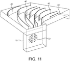
- the chamber 36 may be provided with one or more fins, vanes, baffles or other such airflow redirection means 40 as shown in figure 7 .
- the redirection means 40 ensure an evenly distributed flow of heated air from the fan outlets 34 to the slots 38. This in turn ensures uniformity of the air curtains formed across the apertures 22,24.
- FIGS 8 and 9 show an alternative embodiment of the cabinet 10 described with reference to figures 1 to 7 .
- the cabinet 10 differs in that the portions 16a,16b, 18a,18b of the side walls 16,18 adjacent the apertures 22,24 are glazed. This allows the interior space 20 of the cabinet 10 to be viewed from the side of the cabinet 10.
- the side wall portions 16a,16b may comprise double glazed units which serve to reduce heat transfer therethrough.
- Each aperture 22,24 of the cabinet 10 is further provided with a weir 42 which extends across the lower edge of the aperture 22,24 between the side walls 16,18, and a deflector 44 which extends across the upper edge of the aperture 22,24 between the side walls 16,18.
- Each weir and deflector pair 42,44 acts to guide the air curtain across the aperture 22,24 with which they are associated. It will be understood that such weirs and deflectors may be utilised in conjunction with the cabinet described with reference to figures 1 to 7 .
- FIG. 10 there is shown an alternative embodiment of a cabinet generally designated 100.
- the cabinet 100 of figures 10 and 11 differs in that it is provided with a single fan 26,28 behind each side wall 16, 18.
- FIG. 12 and 13 there are shown two cabinets 10 of the type hereinbefore described incorporated within an installation generally designated 50. More specifically, the cabinets 10 are incorporated into a wall or partition 52 which divides a food preparation area 54 from a food collection area 56.
- the food preparation area 54 includes two ovens 58 which are positioned against the wall 52 on opposing sides of the cabinets 10.
- a food preparation and packaging table 60 is provided adjacent the cabinet apertures 22 on the food preparation area 54 side of the wall 52. It will be understood that cooked food products can be removed from the ovens 58 and packaged on the table 60 before being placed in the cabinets 10. The cooked and packaged food products can thereafter be removed via the cabinet apertures 24 on the opposing side of the wall 52 to the food preparation area.
- Figures 14 to 20 show accessories which may be utilised with the cabinets 10,100 hereinbefore described. More specifically, the accessories are configured to support food products and food product containers within the cabinets 10,100.
- Figures 14 and 16 show a sliding drawer arrangement 66 which may be fitted to a cabinet 10,100.
- the drawer 66 is, in use, mounted to the throat 30 of the cabinet 10 and may be manipulated to extend out of the cabinet 10 through one of the apertures 22,24 thereof. Cooked food products can thereafter be placed on the drawer 66. The drawer 66 can then be manipulated so as to be moved back into the interior space 20 of the cabinet 10.
- the drawer 66 has a perforated base 65 and is mountable to the throat 30 of the cabinet 10 by opposed mounting plates 67.
- FIGs 17 and 18 show a shelving unit 68 for use with the drawer 66 of figures 14 to 16 .
- the shelving unit 68 is fittable to the drawer 66 so as to increase the carrying capacity of the drawer 66.
- the shelving unit 68 is provided with a wire base 69 which is sized to fit within the drawer 66.
- FIGS 19 and 20 show an inclined roller track arrangement 70.
- the roller track arrangement 70 includes an inclined frame 72 having a plurality of rollers 74.
- the rollers 74 may be substituted for PTFE strips or a low friction coating.
- the roller track arrangement 70 is further provided with guide bars 76 which guide the movement of food products or food product packaging supported by the rollers 74.
- the roller track arrangement is inclined in the direction of one of the access apertures.
- the roller track arrangement 70 may be provided so as to lie substantially parallel to the floor of the interior space 20 of the cabinet 10.
- the present invention thus provides a cabinet 10, 100 which is open at opposing ends and which can be operated so as to provide an interior space 20 which can be maintained at an elevated temperature, for example between 50 and 90 degrees centigrade.
- the interior space 20 is accessible though the apertures 22,24 for the purpose of inserting and removing heated food items.
- the air curtains act to maintain the interior space 20 of the cabinet 10 at the required elevated temperature while providing minimal impedance to the insertion and removal of heated food items.
- a cabinet 10, 100 in accordance with the present invention may be used in conjunction with the temporary storage of packaged baked goods such as pizzas and flatbreads.
- the cabinet 10, 100 may advantageously be placed at a location between where such packaged baked goods are prepared and then collected by a purchaser or consumer.
- the baked goods may be removed from the oven in which they have been prepared and placed in an appropriately configured package.
- the package is then placed into the interior space 20 of the cabinet 10, 100, 200 through the aperture 22,24 which faces the preparation location.
- the heated air circulating within the interior space 20 acts to retard the cooling of the baked goods prior to the package being removed by a purchaser or consumer of the baked goods through the other of the cabinet apertures 22,24.
- a plurality of such cabinets 10, 100 may be provided one on top of another so as to provide multiple locations where packaged baked goods may be temporarily stored before collection.
- Degradation of the quality of the baked goods is minimised while within the interior space 20 of the cabinet 10, 100, 200 as the package is not exposed to a directly heated surface such as, for example, an electrically heated hot plate.
- the cabinet 10,100 of the present invention is not limited for use with packaged baked goods, and may be used in conjunction with any heated food item.
- cabinet 10,100 of the present invention is not intended to heat or cook the food items placed within the interior space 20 but instead is intended to retard the cooling of already heated food items.
- the interior space 20 of the cabinet 10,100 may be provided with guide formations which, in use, guide the passage of a heated food item from one aperture 22 to the other aperture 24.
- the interior space 20 may further be provided with one or more shelves so as to allow heated food items to be passed through the interior space from one aperture 22 to the other aperture 24 at different levels.
Description
- The present invention relates to a cabinet for the temporary storage of a heated food item. More specifically, the present invention relates to a cabinet for the temporary storage of a heated food item wherein the cabinet is operable to retard the cooling of the heated food item by the circulation of heated air over and around the food item.
- Changes in working patterns have led to changes in eating habits particularly with respect to what might be called the traditional evening meal where a family sits around a table and eats home-cooked food. It is now becoming increasingly commonplace for convenience meals to be eaten in the evening while watching television from an easy chair. That has, in turn, led to an increase in take-away food outlets where a person can collect a hot ready-cooked meal to eat at home.
- For some time, supermarkets have offered a range of prepared food which can be taken home, heated or cooked, and then eaten. However, there is now increasing competition from take-away food outlets which supermarkets would like to address by supplying hot ready-cooked meals themselves. One of the problems faced by supermarkets is how to keep such food hot whilst making it readily accessible to customers and an object of the present invention is to provide a cabinet which will be suitable for such a purpose.
- In addition to the collection of food from supermarkets, there has also been an increase in the ordering of cooked food products via the internet for home delivery. Typically a consumer will utilise the services of an online food delivery business to have food from a consumer specified restaurant delivered to their home. Delivery to the consumer may be undertaken by delivery drivers or cyclists who collect the cooked food products from a kitchen. The kitchen may be the kitchen of a restaurant. Alternatively the kitchen may be dedicated to the provision of restaurant style cooked food products for home delivery.
- The delivery drivers or cyclists are provided with apparatus such as insulated containers which retard the cooling of the cooked food products during the delivery phase, however there has been identified a need to retard the cooling of the cooked food products in the period after cooking and before collection by a delivery driver or cyclist.
- According to the present invention there is provided a cabinet for the temporary storage of a heated food item, the cabinet having a base, a top and opposing sides, wherein the base, top and opposing sides define an interior space of the cabinet which is accessible through opposing access apertures at each end of the cabinet, wherein the cabinet is provided with air movement means and air heating means operable to draw air from the interior space of the cabinet, heat said air and utilise said heated air to produce air curtains across the opposing access apertures of the cabinet, wherein the width of the interior space between the side walls narrows to a throat at a point approximately midway between the opposing access apertures.
- The present invention provides a cabinet having an interior space that is readily accessible through the apertures to allow a food item to be placed into and thereafter removed from the interior space. The heated air curtains allow the interior space of the cabinet to be maintained at an elevated temperature compared to the ambient temperature surrounding the cabinet.
- The narrowing of the interior space to a throat at a midway point between the opposing access apertures may serve to align food product containers during their passage through the chamber from one access aperture to the other. For example, the width of the throat may be approximately equal to the width of a pizza box. Alignment of food product containers in the manner described above may also prevent the occlusion of apertures through which air is drawn from the interior space by the air movement means.
- The air movement means may comprise an electrically operated fan. The air heating means may comprise an electrically operated heating element. The air movement means may be positioned behind a side wall of the cabinet. In such an embodiment the side wall may be provided with one or more apertures which allow fluid communication between the interior space of the cabinet and the air movement means.
- The cabinet of the present invention may have a single fan and heating element behind each side wall of the cabinet. In an alternative embodiment of the present invention, there may be provided multiple fans and heating elements behind each side wall.
- The cabinet may be provided with a chamber located above the top of the interior space which, in use, receives heated air from the air movement means. The chamber may be provided with slots positioned above the access apertures, wherein the slots are configured to direct heated air from the chamber across the access apertures to form the air curtains. Such slots may extend substantially across the width of the chamber. It will thus be appreciated that each slot can create an air curtain that extends substantially fully across an access aperture of the cabinet.
-
US-A-3 942 426 shows a heated sanitary sandwich bin with air curtains. - Embodiments of the present invention will now be described with reference to the accompanying drawings in which:
-
Figure 1 shows a perspective view of a partially completed cabinet according to an embodiment of the present invention; -
Figure 2 shows an end view of the cabinet offigure 1 ; -
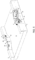
Figure 3 shows a side view of the cabinet offigure 1 ; -
Figure 4 shows a top plan view of the cabinet offigure 1 ; -
Figure 5 shows a partially sectioned view of the cabinet offigure 1 ; -
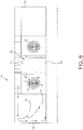
Figure 6 shows another partially sectioned view of the cabinet offigure 1 ; -
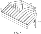
Figure 7 shows a perspective view of a diffuser of the cabinet; -
Figure 8 shows a sectioned plan view of a cabinet of an alternative embodiment of the present invention; -
Figure 9 shows a perspective view of the cabinet offigure 8 ; -
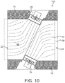
Figure 10 shows a partially sectioned view of an alternative embodiment of a cabinet; -
Figure 11 shows a perspective view of a diffuser of the cabinet offigure 10 ; -
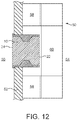
Figure 12 shows a plan view of an installation having a cabinet according to the present invention; -
Figure 13 shows a perspective view of the installation offigure 12 ; -
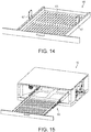
Figure 14 shows a perspective view of a drawer unit; -
Figure 15 shows a perspective view of a cabinet and a drawer unit; -
Figure 16 shows a further perspective view of a cabinet and a drawer unit; -
Figure 17 shows a perspective view of a shelving unit; -
Figure 18 shows a perspective view of the shelving unit fitted to the cabinet and drawer unit offigure 15 ; -
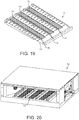
Figure 19 shows a perspective view of a roller track arrangement; and -
Figure 20 shows a perspective view of the roller track arrangement and the cabinet. - Referring to
figures 1 to 7 there is shown a cabinet, generally designated 10, which may be used for the temporary storage of a heated food item. As will be described in greater detail below, thecabinet 10 is intended to retard the cooling of heated food item before collection of the food item by a consumer or purchaser of the food item. The retarded cooling effect is achieved by the circulation of heated air over and around the food item. - The
cabinet 10 includes abase 12, atop 14 andopposing side walls top 14 is formed from twotop panels 14a,14b Thebase 12,top 14 andside walls interior space 20 of thecabinet 10 which, in use, can temporarily accommodate a heated food item. Thebase 12,top 14 andside walls rectangular apertures interior space 20. Thebase 12,top 14 andside walls - Each
side wall apertures electric fans fan closest aperture fans 26 are inclined towardsaperture 22 andfans 28 are inclined towardsaperture 24. As can be seen fromfigure 5 , the inclination of thefans interior space 20 of thecabinet 10 to athroat 30 positioned substantially equidistantly within thecabinet 10 between theapertures - Each
fan side wall inlet apertures 32. Eachfan interior space 20 ofcabinet 10 through theinlet apertures 32. Air drawn by eachfan inlet apertures 32 is heated byheater elements 31 which are located adjacent thefans fans - The
fans - It will be appreciated that the width of the
interior space 20 at thethroat 30 defines the maximum width for food products and/or their packaging that are able to pass through theinterior space 20 from oneaperture 22 to theother aperture 24. It will further be appreciated that the inclination of theside walls fans throat 30 as the food product and/or its packaging are advanced through thecabinet 10 from oneaperture 22 to the other 24. This alignment with respect to thethroat 30 may ensure that a food product and/or its packaging does not foul, block or otherwise occlude thefan inlet apertures 32. - The heated air is delivered by each
fan outlet 34 positioned above thetop panels 14a, 14b of thecabinet 10. Theoutlets 34 communicate with achamber 36 which is positioned above theinterior space 20 of thecabinet 10. In the accompanying figures thechamber 36 is shown to be open topped. The open top is shown for the purpose of illustrating the internal configuration of thecabinet 10. In use, a cover (not shown) overlies the top 14 of thechamber 36. - The top 14 of the
cabinet 10 is provided with a pair ofslots 38 each of which extends across the top 14 above anaperture cabinet 10. Eachslot 38 extends across substantially the whole width of theinterior space 20 of thecabinet 10 and, in use, is used to form an air curtain across eachaperture - Air drawn from the
interior space 20 of thecabinet 10 through theapertures 32 is heated and then delivered to thechamber 36 through theoutlets 34. The heated air moves through thechamber 36 to theslots 38 whereupon it is directed downwardly through theslots 38 and across thecabinet apertures slot 38 forms an air curtain across therespective cabinet aperture interior space 20 of thecabinet 10. Movement of the air within the cabinet as described above is indicated with arrows. As can be seen, a portion of the air delivered through eachslot 38 forms an air curtain, while another portion of the air delivered through eachslot 38 circulates within theinterior space 20 to heat theinterior space 20. - To assist with the movement of the heated air from the
fan outlets 34 to theslots 38, thechamber 36 may be provided with one or more fins, vanes, baffles or other such airflow redirection means 40 as shown infigure 7 . The redirection means 40 ensure an evenly distributed flow of heated air from thefan outlets 34 to theslots 38. This in turn ensures uniformity of the air curtains formed across theapertures -
Figures 8 and 9 show an alternative embodiment of thecabinet 10 described with reference tofigures 1 to 7 . Features common to the embodiment described with reference tofigures 1 to 7 are identified with like reference numerals. Thecabinet 10 differs in that theportions side walls apertures interior space 20 of thecabinet 10 to be viewed from the side of thecabinet 10. Theside wall portions - Each
aperture cabinet 10 is further provided with aweir 42 which extends across the lower edge of theaperture side walls deflector 44 which extends across the upper edge of theaperture side walls deflector pair aperture figures 1 to 7 . - Referring now to
figures 10 and11 there is shown an alternative embodiment of a cabinet generally designated 100. Features common to the cabinet described with reference tofigures 1 to 9 identified with like reference numerals. Thecabinet 100 offigures 10 and11 differs in that it is provided with asingle fan side wall - Referring now to
figures 12 and13 there are shown twocabinets 10 of the type hereinbefore described incorporated within an installation generally designated 50. More specifically, thecabinets 10 are incorporated into a wall orpartition 52 which divides afood preparation area 54 from afood collection area 56. In the embodiment shown, thefood preparation area 54 includes twoovens 58 which are positioned against thewall 52 on opposing sides of thecabinets 10. A food preparation and packaging table 60 is provided adjacent the cabinet apertures 22 on thefood preparation area 54 side of thewall 52. It will be understood that cooked food products can be removed from theovens 58 and packaged on the table 60 before being placed in thecabinets 10. The cooked and packaged food products can thereafter be removed via the cabinet apertures 24 on the opposing side of thewall 52 to the food preparation area. -
Figures 14 to 20 show accessories which may be utilised with the cabinets 10,100 hereinbefore described. More specifically, the accessories are configured to support food products and food product containers within the cabinets 10,100. -
Figures 14 and16 show a slidingdrawer arrangement 66 which may be fitted to a cabinet 10,100. Thedrawer 66 is, in use, mounted to thethroat 30 of thecabinet 10 and may be manipulated to extend out of thecabinet 10 through one of theapertures drawer 66. Thedrawer 66 can then be manipulated so as to be moved back into theinterior space 20 of thecabinet 10. - The
drawer 66 has a perforatedbase 65 and is mountable to thethroat 30 of thecabinet 10 by opposed mountingplates 67. -
Figures 17 and 18 show ashelving unit 68 for use with thedrawer 66 offigures 14 to 16 . Theshelving unit 68 is fittable to thedrawer 66 so as to increase the carrying capacity of thedrawer 66. Theshelving unit 68 is provided with awire base 69 which is sized to fit within thedrawer 66. -
Figures 19 and 20 show an inclinedroller track arrangement 70. Theroller track arrangement 70 includes aninclined frame 72 having a plurality ofrollers 74. Therollers 74 may be substituted for PTFE strips or a low friction coating. Theroller track arrangement 70 is further provided withguide bars 76 which guide the movement of food products or food product packaging supported by therollers 74. In the embodiment shown the roller track arrangement is inclined in the direction of one of the access apertures. In an alternative embodiment theroller track arrangement 70 may be provided so as to lie substantially parallel to the floor of theinterior space 20 of thecabinet 10. - The present invention thus provides a
cabinet interior space 20 which can be maintained at an elevated temperature, for example between 50 and 90 degrees centigrade. Theinterior space 20 is accessible though theapertures interior space 20 of thecabinet 10 at the required elevated temperature while providing minimal impedance to the insertion and removal of heated food items. - A
cabinet cabinet interior space 20 of thecabinet aperture - The heated air circulating within the
interior space 20 acts to retard the cooling of the baked goods prior to the package being removed by a purchaser or consumer of the baked goods through the other of thecabinet apertures - A plurality of
such cabinets - Degradation of the quality of the baked goods is minimised while within the
interior space 20 of thecabinet - The cabinet 10,100 of the present invention is not limited for use with packaged baked goods, and may be used in conjunction with any heated food item.
- It will be understood that the cabinet 10,100 of the present invention is not intended to heat or cook the food items placed within the
interior space 20 but instead is intended to retard the cooling of already heated food items. - The
interior space 20 of the cabinet 10,100 may be provided with guide formations which, in use, guide the passage of a heated food item from oneaperture 22 to theother aperture 24. Theinterior space 20 may further be provided with one or more shelves so as to allow heated food items to be passed through the interior space from oneaperture 22 to theother aperture 24 at different levels.
Claims (14)
- A cabinet (10) for the temporary storage of a heated food item, the cabinet having a base (12), a top (14) and opposing sides (16, 18), wherein the base (12), top (14) and opposing sides (16, 18) define an interior space (20) of the cabinet (10) which is accessible through opposing access apertures (22, 24) at each end of the cabinet (10), wherein the cabinet (10) is provided with air movement means (26, 28) and air heating means (31) operable to draw air from the interior space (20) of the cabinet, heat said air and utilise said heated air to produce air curtains across the opposing access apertures (22, 24) of the cabinet (10), characterised in that the width of the interior space (20) between the side walls (16, 18) narrows to a throat (30) at a point approximately midway between the opposing access apertures (22, 24).
- A cabinet (10) as claimed in claim 1 wherein a portion of said heated air is utilised to produce said air curtains and a further portion of the heated air is circulated within said interior space (20).
- A cabinet (10) as claimed in claim 1 or claim 2 wherein the air movement means comprise an electrically operated fan (26, 28).
- A cabinet (10) as claimed in any preceding claim wherein the air heating means comprise an electrically operated heating element (31).
- A cabinet (10) as claimed in any preceding claim wherein the air movement means are positioned beside a side wall (16, 18) of the cabinet (10) and on the opposite side of the side wall (16, 18) to the interior space of the cabinet (10).
- A cabinet (10) as claimed in claim 5 wherein the side wall (16, 18) is provided with one or more apertures (34) which allow fluid communication between the interior space of the cabinet (10) and the air movement means (26, 28).
- A cabinet (10) as claimed in any preceding claim and including a chamber (36) located above the top of the interior space (20) which, in use, receives heated air from the air movement means (26, 28).
- A cabinet (10) as claimed in claim 7 wherein the chamber (36) includes slots (38) positioned above the access apertures (22, 24), wherein said slots (38) are configured to direct heated air from the chamber (36) across the access apertures (22, 24) to form the air curtains.
- A cabinet (10) as clamed in claim 8 wherein the chamber (36) further includes airflow direction means (40) arranged to direct air received from the air movement (26, 28) means to the slots (38).
- A cabinet (10) as claimed in any preceding claim wherein the interior space (20) is provided with one or more shelves.
- A cabinet (10) as claimed in any preceding claim wherein the interior space (20) is provided with one or more guide means configured to guide the movement of food products through the interior space (20) from one access aperture (22, 24) to the other access aperture (22, 24).
- A cabinet (10) as claimed in claim 11 wherein the guide means comprise a drawer (66) of the cabinet (10).
- A cabinet (10) as claimed in claim 11 wherein the guide means comprise a roller bed (70) of the cabinet (10).
- A cabinet (10) as claimed in claim 13 wherein the roller bed is inclined in the direction of one of the access apertures (22, 24).
Priority Applications (1)
| Application Number | Priority Date | Filing Date | Title |
|---|---|---|---|
| PL18755283T PL3661399T3 (en) | 2017-08-04 | 2018-08-06 | Cabinet with opposed air curtains |
Applications Claiming Priority (2)
| Application Number | Priority Date | Filing Date | Title |
|---|---|---|---|
| GBGB1712559.2A GB201712559D0 (en) | 2017-08-04 | 2017-08-04 | Cabinet with opposed air curtains |
| PCT/GB2018/052240 WO2019025822A1 (en) | 2017-08-04 | 2018-08-06 | Cabinet with opposed air curtains |
Publications (2)
| Publication Number | Publication Date |
|---|---|
| EP3661399A1 EP3661399A1 (en) | 2020-06-10 |
| EP3661399B1 true EP3661399B1 (en) | 2021-04-21 |
Family
ID=59894752
Family Applications (1)
| Application Number | Title | Priority Date | Filing Date |
|---|---|---|---|
| EP18755283.1A Active EP3661399B1 (en) | 2017-08-04 | 2018-08-06 | Cabinet with opposed air curtains |
Country Status (7)
| Country | Link |
|---|---|
| US (1) | US11503954B2 (en) |
| EP (1) | EP3661399B1 (en) |
| AU (1) | AU2018311353B2 (en) |
| ES (1) | ES2877225T3 (en) |
| GB (1) | GB201712559D0 (en) |
| PL (1) | PL3661399T3 (en) |
| WO (1) | WO2019025822A1 (en) |
Families Citing this family (2)
| Publication number | Priority date | Publication date | Assignee | Title |
|---|---|---|---|---|
| US11533784B2 (en) * | 2019-09-24 | 2022-12-20 | Sanden Vendo America, Inc. | Hot food merchandising unit with roller grill |
| GB202207258D0 (en) | 2022-05-18 | 2022-06-29 | Alan Nuttall Partnership Ltd | Cabinet with air curtain |
Family Cites Families (35)
| Publication number | Priority date | Publication date | Assignee | Title |
|---|---|---|---|---|
| US3628447A (en) * | 1970-01-26 | 1971-12-21 | Joseph M Linsey Corp | Hot food display unit |
| US3632968A (en) * | 1970-12-14 | 1972-01-04 | Robert G Wilson | Self-service food warmer assembly |
| US3778964A (en) * | 1971-11-15 | 1973-12-18 | Roll O Sheets | Apparatus for shrink packaging |
| US3780794A (en) * | 1971-12-02 | 1973-12-25 | B Staub | Food table |
| US3942426A (en) | 1975-04-14 | 1976-03-09 | Restaurant Technology, Inc. | Heated sanitary sandwich bin with air curtains |
| US4074108A (en) * | 1976-09-13 | 1978-02-14 | Henny Penny Corporation | Countertop display warmer |
| DE7711392U1 (en) | 1977-04-12 | 1977-07-21 | Ludwig Kiesel Ohg, 8500 Nuernberg | SELF-SERVICE FROZEN DISPLAY CASE |
| US4343985A (en) * | 1977-11-07 | 1982-08-10 | Robert G. Wilson | Counter top food warmer and display case |
| US4267706A (en) * | 1979-05-31 | 1981-05-19 | Tyler Refrigeration Corporation | Shop around refrigerated merchandiser |
| US4437396A (en) * | 1982-09-28 | 1984-03-20 | Bastian Blessing Co., Inc. | Air heated sandwich bin |
| AU1452092A (en) * | 1991-03-12 | 1992-10-21 | Thermocar Holland B.V. I.O. | Apparatus for transport of warm foodstuffs |
| CA2282990C (en) * | 1998-09-23 | 2005-03-22 | Keith A. Stanger | Method and apparatus for providing extended fried food holding times |
| ES1041549Y (en) * | 1998-11-13 | 2000-01-01 | Mellado Antonio Criado | IMPROVED FURNITURE FOR FOOD EXPOSURE AND CONSERVATION. |
| US6114659A (en) * | 1999-04-15 | 2000-09-05 | The Frymaster Corporation | Device and method for keeping food warm |
| AU4452600A (en) * | 1999-04-28 | 2000-11-10 | Henny Penny Corporation | Food merchandiser with reconfigurable food wells |
| GB0017278D0 (en) * | 2000-07-13 | 2000-08-30 | Alan Nuttall Limited | A heated food storage and display cabinet |
| US7121104B2 (en) * | 2004-09-23 | 2006-10-17 | Delaware Capital Formation, Inc. | Adjustable shelf system for refrigerated case |
| GB0508204D0 (en) * | 2005-04-22 | 2005-06-01 | Alan Nuttall Ltd | Heated food storage and display cabinet |
| US8134101B2 (en) * | 2007-10-11 | 2012-03-13 | Hatco Corporation | Food container |
| US20090139976A1 (en) * | 2007-12-03 | 2009-06-04 | Robert Lee | Impingement quartz conveyor oven |
| US8437627B1 (en) * | 2008-09-11 | 2013-05-07 | Meister Cook, LLC | Apparatus for extending the holding time for food |
| KR200450319Y1 (en) | 2010-01-28 | 2010-09-20 | 성진하이쿨(주) | Open Type Refrigeration Show-Case |
| US8895902B2 (en) * | 2010-03-17 | 2014-11-25 | Duke Manufacturing Co. | Oven for heating food |
| US8362404B2 (en) * | 2010-05-17 | 2013-01-29 | Carter Hoffmann, Inc. | Open warming cabinet |
| US20120051722A1 (en) * | 2010-08-23 | 2012-03-01 | Humphrey James E | Heated air curtain warmer |
| US9027470B1 (en) * | 2011-03-18 | 2015-05-12 | Meister Cook Llc | Food condition maintaining device |
| US9962037B2 (en) * | 2011-03-18 | 2018-05-08 | Meister Cook, LLC | Food condition maintaining device |
| WO2013062830A2 (en) * | 2011-10-24 | 2013-05-02 | Manitowoc Foodservice Companies, Llc | Multiple tier holding display and method |
| EP2716190B1 (en) * | 2012-10-05 | 2015-09-30 | Team-Kalorik-Group N.V./S.A. | Device for keeping food warm |
| EP2716191A1 (en) | 2012-10-05 | 2014-04-09 | Team-Kalorik-Group N.V. | Device for keeping food warm |
| GB2509207B (en) * | 2012-11-06 | 2014-11-05 | Alan Nuttall Ltd | Open fronted cabinet |
| US9149154B1 (en) * | 2013-03-04 | 2015-10-06 | Marshall Air Systems, Inc. | Apparatus for transiently holding cooked food in a warm condition pending service of the food for consumption |
| GB201316911D0 (en) * | 2013-09-24 | 2013-11-06 | Alan Nuttall Ltd | Energy saving food storage unit |
| KR101622519B1 (en) | 2015-10-30 | 2016-05-18 | (주)헤움 | Air oven type grill |
| NL2017055B1 (en) * | 2016-06-27 | 2018-01-05 | Fri Jado Bv | Display unit for storing and displaying heated goods, and use of a display unit |
-
2017
- 2017-08-04 GB GBGB1712559.2A patent/GB201712559D0/en not_active Ceased
-
2018
- 2018-08-06 ES ES18755283T patent/ES2877225T3/en active Active
- 2018-08-06 US US16/636,253 patent/US11503954B2/en active Active
- 2018-08-06 WO PCT/GB2018/052240 patent/WO2019025822A1/en unknown
- 2018-08-06 PL PL18755283T patent/PL3661399T3/en unknown
- 2018-08-06 EP EP18755283.1A patent/EP3661399B1/en active Active
- 2018-08-06 AU AU2018311353A patent/AU2018311353B2/en active Active
Non-Patent Citations (1)
| Title |
|---|
| None * |
Also Published As
| Publication number | Publication date |
|---|---|
| ES2877225T3 (en) | 2021-11-16 |
| WO2019025822A1 (en) | 2019-02-07 |
| AU2018311353A1 (en) | 2020-02-20 |
| EP3661399A1 (en) | 2020-06-10 |
| GB201712559D0 (en) | 2017-09-20 |
| US11503954B2 (en) | 2022-11-22 |
| PL3661399T3 (en) | 2021-09-27 |
| US20200367694A1 (en) | 2020-11-26 |
| AU2018311353B2 (en) | 2020-10-15 |
| NZ761228A (en) | 2021-09-24 |
Similar Documents
| Publication | Publication Date | Title |
|---|---|---|
| AU637559B2 (en) | Air delivery system and oven control circuitry cooling system for a low profile impingement oven | |
| EP1885220B1 (en) | Heated food storage and display cabinet | |
| US8063342B2 (en) | Cooking oven | |
| US20160356505A1 (en) | Convection oven having removable air plenums | |
| US7372000B2 (en) | Air control for a brick oven | |
| US20020012729A1 (en) | Cooked food staging device and method | |
| US11297977B1 (en) | Double air fryer | |
| WO2000057709A8 (en) | Holding or cooking oven | |
| NL8006470A (en) | OVEN. | |
| EP3661399B1 (en) | Cabinet with opposed air curtains | |
| US20210251422A1 (en) | Rack assembly | |
| EP0407982A2 (en) | Method and apparatus for simulating open flame broiled meat products | |
| US9149154B1 (en) | Apparatus for transiently holding cooked food in a warm condition pending service of the food for consumption | |
| US20120204733A1 (en) | Cooking System | |
| NZ761228B2 (en) | Cabinet with opposed air curtains | |
| US11930960B2 (en) | Cooking apparatuses | |
| WO2023223029A1 (en) | Cabinet with air curtain | |
| EP4297620A1 (en) | Cooking apparatuses | |
| MXPA06003955A (en) | Food warming apparatus and method |
Legal Events
| Date | Code | Title | Description |
|---|---|---|---|
| STAA | Information on the status of an ep patent application or granted ep patent |
Free format text: STATUS: UNKNOWN |
|
| STAA | Information on the status of an ep patent application or granted ep patent |
Free format text: STATUS: THE INTERNATIONAL PUBLICATION HAS BEEN MADE |
|
| PUAI | Public reference made under article 153(3) epc to a published international application that has entered the european phase |
Free format text: ORIGINAL CODE: 0009012 |
|
| STAA | Information on the status of an ep patent application or granted ep patent |
Free format text: STATUS: REQUEST FOR EXAMINATION WAS MADE |
|
| 17P | Request for examination filed |
Effective date: 20200116 |
|
| AK | Designated contracting states |
Kind code of ref document: A1 Designated state(s): AL AT BE BG CH CY CZ DE DK EE ES FI FR GB GR HR HU IE IS IT LI LT LU LV MC MK MT NL NO PL PT RO RS SE SI SK SM TR |
|
| AX | Request for extension of the european patent |
Extension state: BA ME |
|
| REG | Reference to a national code |
Ref country code: HK Ref legal event code: DE Ref document number: 40019722 Country of ref document: HK |
|
| DAV | Request for validation of the european patent (deleted) | ||
| DAX | Request for extension of the european patent (deleted) | ||
| GRAP | Despatch of communication of intention to grant a patent |
Free format text: ORIGINAL CODE: EPIDOSNIGR1 |
|
| STAA | Information on the status of an ep patent application or granted ep patent |
Free format text: STATUS: GRANT OF PATENT IS INTENDED |
|
| INTG | Intention to grant announced |
Effective date: 20201124 |
|
| RAP1 | Party data changed (applicant data changed or rights of an application transferred) |
Owner name: THE ALAN NUTTALL PARTNERSHIP LIMITED |
|
| GRAS | Grant fee paid |
Free format text: ORIGINAL CODE: EPIDOSNIGR3 |
|
| GRAA | (expected) grant |
Free format text: ORIGINAL CODE: 0009210 |
|
| STAA | Information on the status of an ep patent application or granted ep patent |
Free format text: STATUS: THE PATENT HAS BEEN GRANTED |
|
| AK | Designated contracting states |
Kind code of ref document: B1 Designated state(s): AL AT BE BG CH CY CZ DE DK EE ES FI FR GB GR HR HU IE IS IT LI LT LU LV MC MK MT NL NO PL PT RO RS SE SI SK SM TR |
|
| REG | Reference to a national code |
Ref country code: GB Ref legal event code: FG4D |
|
| REG | Reference to a national code |
Ref country code: CH Ref legal event code: EP |
|
| REG | Reference to a national code |
Ref country code: DE Ref legal event code: R096 Ref document number: 602018015945 Country of ref document: DE Ref country code: IE Ref legal event code: FG4D |
|
| REG | Reference to a national code |
Ref country code: AT Ref legal event code: REF Ref document number: 1383737 Country of ref document: AT Kind code of ref document: T Effective date: 20210515 |
|
| REG | Reference to a national code |
Ref country code: FI Ref legal event code: FGE |
|
| REG | Reference to a national code |
Ref country code: NL Ref legal event code: FP |
|
| REG | Reference to a national code |
Ref country code: SE Ref legal event code: TRGR |
|
| REG | Reference to a national code |
Ref country code: NO Ref legal event code: T2 Effective date: 20210421 |
|
| REG | Reference to a national code |
Ref country code: GR Ref legal event code: EP Ref document number: 20210401551 Country of ref document: GR Effective date: 20210709 |
|
| REG | Reference to a national code |
Ref country code: LT Ref legal event code: MG9D |
|
| PG25 | Lapsed in a contracting state [announced via postgrant information from national office to epo] |
Ref country code: HR Free format text: LAPSE BECAUSE OF FAILURE TO SUBMIT A TRANSLATION OF THE DESCRIPTION OR TO PAY THE FEE WITHIN THE PRESCRIBED TIME-LIMIT Effective date: 20210421 Ref country code: LT Free format text: LAPSE BECAUSE OF FAILURE TO SUBMIT A TRANSLATION OF THE DESCRIPTION OR TO PAY THE FEE WITHIN THE PRESCRIBED TIME-LIMIT Effective date: 20210421 Ref country code: BG Free format text: LAPSE BECAUSE OF FAILURE TO SUBMIT A TRANSLATION OF THE DESCRIPTION OR TO PAY THE FEE WITHIN THE PRESCRIBED TIME-LIMIT Effective date: 20210721 |
|
| REG | Reference to a national code |
Ref country code: ES Ref legal event code: FG2A Ref document number: 2877225 Country of ref document: ES Kind code of ref document: T3 Effective date: 20211116 |
|
| PG25 | Lapsed in a contracting state [announced via postgrant information from national office to epo] |
Ref country code: LV Free format text: LAPSE BECAUSE OF FAILURE TO SUBMIT A TRANSLATION OF THE DESCRIPTION OR TO PAY THE FEE WITHIN THE PRESCRIBED TIME-LIMIT Effective date: 20210421 Ref country code: PT Free format text: LAPSE BECAUSE OF FAILURE TO SUBMIT A TRANSLATION OF THE DESCRIPTION OR TO PAY THE FEE WITHIN THE PRESCRIBED TIME-LIMIT Effective date: 20210823 Ref country code: RS Free format text: LAPSE BECAUSE OF FAILURE TO SUBMIT A TRANSLATION OF THE DESCRIPTION OR TO PAY THE FEE WITHIN THE PRESCRIBED TIME-LIMIT Effective date: 20210421 Ref country code: IS Free format text: LAPSE BECAUSE OF FAILURE TO SUBMIT A TRANSLATION OF THE DESCRIPTION OR TO PAY THE FEE WITHIN THE PRESCRIBED TIME-LIMIT Effective date: 20210821 |
|
| REG | Reference to a national code |
Ref country code: DE Ref legal event code: R097 Ref document number: 602018015945 Country of ref document: DE |
|
| PG25 | Lapsed in a contracting state [announced via postgrant information from national office to epo] |
Ref country code: EE Free format text: LAPSE BECAUSE OF FAILURE TO SUBMIT A TRANSLATION OF THE DESCRIPTION OR TO PAY THE FEE WITHIN THE PRESCRIBED TIME-LIMIT Effective date: 20210421 Ref country code: SK Free format text: LAPSE BECAUSE OF FAILURE TO SUBMIT A TRANSLATION OF THE DESCRIPTION OR TO PAY THE FEE WITHIN THE PRESCRIBED TIME-LIMIT Effective date: 20210421 Ref country code: CZ Free format text: LAPSE BECAUSE OF FAILURE TO SUBMIT A TRANSLATION OF THE DESCRIPTION OR TO PAY THE FEE WITHIN THE PRESCRIBED TIME-LIMIT Effective date: 20210421 Ref country code: DK Free format text: LAPSE BECAUSE OF FAILURE TO SUBMIT A TRANSLATION OF THE DESCRIPTION OR TO PAY THE FEE WITHIN THE PRESCRIBED TIME-LIMIT Effective date: 20210421 Ref country code: RO Free format text: LAPSE BECAUSE OF FAILURE TO SUBMIT A TRANSLATION OF THE DESCRIPTION OR TO PAY THE FEE WITHIN THE PRESCRIBED TIME-LIMIT Effective date: 20210421 Ref country code: SM Free format text: LAPSE BECAUSE OF FAILURE TO SUBMIT A TRANSLATION OF THE DESCRIPTION OR TO PAY THE FEE WITHIN THE PRESCRIBED TIME-LIMIT Effective date: 20210421 |
|
| PLBE | No opposition filed within time limit |
Free format text: ORIGINAL CODE: 0009261 |
|
| STAA | Information on the status of an ep patent application or granted ep patent |
Free format text: STATUS: NO OPPOSITION FILED WITHIN TIME LIMIT |
|
| 26N | No opposition filed |
Effective date: 20220124 |
|
| REG | Reference to a national code |
Ref country code: CH Ref legal event code: PL |
|
| PG25 | Lapsed in a contracting state [announced via postgrant information from national office to epo] |
Ref country code: MC Free format text: LAPSE BECAUSE OF FAILURE TO SUBMIT A TRANSLATION OF THE DESCRIPTION OR TO PAY THE FEE WITHIN THE PRESCRIBED TIME-LIMIT Effective date: 20210421 |
|
| REG | Reference to a national code |
Ref country code: BE Ref legal event code: MM Effective date: 20210831 |
|
| PG25 | Lapsed in a contracting state [announced via postgrant information from national office to epo] |
Ref country code: LI Free format text: LAPSE BECAUSE OF NON-PAYMENT OF DUE FEES Effective date: 20210831 Ref country code: CH Free format text: LAPSE BECAUSE OF NON-PAYMENT OF DUE FEES Effective date: 20210831 |
|
| PG25 | Lapsed in a contracting state [announced via postgrant information from national office to epo] |
Ref country code: IS Free format text: LAPSE BECAUSE OF FAILURE TO SUBMIT A TRANSLATION OF THE DESCRIPTION OR TO PAY THE FEE WITHIN THE PRESCRIBED TIME-LIMIT Effective date: 20210821 Ref country code: LU Free format text: LAPSE BECAUSE OF NON-PAYMENT OF DUE FEES Effective date: 20210806 Ref country code: AL Free format text: LAPSE BECAUSE OF FAILURE TO SUBMIT A TRANSLATION OF THE DESCRIPTION OR TO PAY THE FEE WITHIN THE PRESCRIBED TIME-LIMIT Effective date: 20210421 |
|
| PG25 | Lapsed in a contracting state [announced via postgrant information from national office to epo] |
Ref country code: BE Free format text: LAPSE BECAUSE OF NON-PAYMENT OF DUE FEES Effective date: 20210831 |
|
| PG25 | Lapsed in a contracting state [announced via postgrant information from national office to epo] |
Ref country code: CY Free format text: LAPSE BECAUSE OF FAILURE TO SUBMIT A TRANSLATION OF THE DESCRIPTION OR TO PAY THE FEE WITHIN THE PRESCRIBED TIME-LIMIT Effective date: 20210421 |
|
| PG25 | Lapsed in a contracting state [announced via postgrant information from national office to epo] |
Ref country code: HU Free format text: LAPSE BECAUSE OF FAILURE TO SUBMIT A TRANSLATION OF THE DESCRIPTION OR TO PAY THE FEE WITHIN THE PRESCRIBED TIME-LIMIT; INVALID AB INITIO Effective date: 20180806 |
|
| PGFP | Annual fee paid to national office [announced via postgrant information from national office to epo] |
Ref country code: NL Payment date: 20230821 Year of fee payment: 6 |
|
| PGFP | Annual fee paid to national office [announced via postgrant information from national office to epo] |
Ref country code: NO Payment date: 20230824 Year of fee payment: 6 Ref country code: IT Payment date: 20230822 Year of fee payment: 6 Ref country code: IE Payment date: 20230822 Year of fee payment: 6 Ref country code: GB Payment date: 20230817 Year of fee payment: 6 Ref country code: FI Payment date: 20230821 Year of fee payment: 6 Ref country code: AT Payment date: 20230822 Year of fee payment: 6 |
|
| REG | Reference to a national code |
Ref country code: AT Ref legal event code: UEP Ref document number: 1383737 Country of ref document: AT Kind code of ref document: T Effective date: 20210421 |
|
| PGFP | Annual fee paid to national office [announced via postgrant information from national office to epo] |
Ref country code: SE Payment date: 20230821 Year of fee payment: 6 Ref country code: PL Payment date: 20230727 Year of fee payment: 6 Ref country code: GR Payment date: 20230822 Year of fee payment: 6 Ref country code: FR Payment date: 20230828 Year of fee payment: 6 Ref country code: DE Payment date: 20230821 Year of fee payment: 6 |
|
| PGFP | Annual fee paid to national office [announced via postgrant information from national office to epo] |
Ref country code: ES Payment date: 20231027 Year of fee payment: 6 |