EP3661321A1 - Distributed antenna system architectures - Google Patents
Distributed antenna system architectures Download PDFInfo
- Publication number
- EP3661321A1 EP3661321A1 EP20151471.8A EP20151471A EP3661321A1 EP 3661321 A1 EP3661321 A1 EP 3661321A1 EP 20151471 A EP20151471 A EP 20151471A EP 3661321 A1 EP3661321 A1 EP 3661321A1
- Authority
- EP
- European Patent Office
- Prior art keywords
- unit
- signal
- remote antenna
- downstream
- upstream
- Prior art date
- Legal status (The legal status is an assumption and is not a legal conclusion. Google has not performed a legal analysis and makes no representation as to the accuracy of the status listed.)
- Withdrawn
Links
Images


Classifications
-
- H—ELECTRICITY
- H03—ELECTRONIC CIRCUITRY
- H03F—AMPLIFIERS
- H03F1/00—Details of amplifiers with only discharge tubes, only semiconductor devices or only unspecified devices as amplifying elements
- H03F1/32—Modifications of amplifiers to reduce non-linear distortion
- H03F1/3241—Modifications of amplifiers to reduce non-linear distortion using predistortion circuits
- H03F1/3247—Modifications of amplifiers to reduce non-linear distortion using predistortion circuits using feedback acting on predistortion circuits
-
- H—ELECTRICITY
- H04—ELECTRIC COMMUNICATION TECHNIQUE
- H04B—TRANSMISSION
- H04B1/00—Details of transmission systems, not covered by a single one of groups H04B3/00 - H04B13/00; Details of transmission systems not characterised by the medium used for transmission
- H04B1/38—Transceivers, i.e. devices in which transmitter and receiver form a structural unit and in which at least one part is used for functions of transmitting and receiving
- H04B1/40—Circuits
- H04B1/50—Circuits using different frequencies for the two directions of communication
- H04B1/52—Hybrid arrangements, i.e. arrangements for transition from single-path two-direction transmission to single-direction transmission on each of two paths or vice versa
- H04B1/525—Hybrid arrangements, i.e. arrangements for transition from single-path two-direction transmission to single-direction transmission on each of two paths or vice versa with means for reducing leakage of transmitter signal into the receiver
-
- H—ELECTRICITY
- H04—ELECTRIC COMMUNICATION TECHNIQUE
- H04L—TRANSMISSION OF DIGITAL INFORMATION, e.g. TELEGRAPHIC COMMUNICATION
- H04L25/00—Baseband systems
- H04L25/02—Details ; arrangements for supplying electrical power along data transmission lines
- H04L25/03—Shaping networks in transmitter or receiver, e.g. adaptive shaping networks
- H04L25/03006—Arrangements for removing intersymbol interference
- H04L25/03343—Arrangements at the transmitter end
-
- H—ELECTRICITY
- H04—ELECTRIC COMMUNICATION TECHNIQUE
- H04L—TRANSMISSION OF DIGITAL INFORMATION, e.g. TELEGRAPHIC COMMUNICATION
- H04L5/00—Arrangements affording multiple use of the transmission path
- H04L5/14—Two-way operation using the same type of signal, i.e. duplex
- H04L5/1423—Two-way operation using the same type of signal, i.e. duplex for simultaneous baseband signals
-
- H—ELECTRICITY
- H04—ELECTRIC COMMUNICATION TECHNIQUE
- H04W—WIRELESS COMMUNICATION NETWORKS
- H04W88/00—Devices specially adapted for wireless communication networks, e.g. terminals, base stations or access point devices
- H04W88/08—Access point devices
- H04W88/085—Access point devices with remote components
Definitions
- This disclosure relates to distributed antenna systems, repeaters, distributed base station systems, and the like.
- One embodiment is directed to a distributed antenna system comprising a host unit and at least one remote antenna unit that is communicatively coupled to the host unit.
- the host unit is configured to communicate a downstream transport signal from the host unit to the remote antenna unit.
- the remote antenna unit to which the downstream transport signal is communicated uses the downstream transport signal to generate a downstream radio frequency signal for radiation from an antenna associated with the remote antenna unit.
- the remote antenna unit is configured to communicate an upstream transport signal from the remote antenna unit to the host unit, wherein the upstream transport signal is generated from a received upstream radio frequency signal received at the remote antenna unit.
- the remote antenna unit is configured to perform self-interference suppression processing in an upstream signal path using, as an input thereto, a feedback signal derived from the downstream radio frequency signal radiated from the antenna.
- the remote antenna unit comprises a transport interface to communicatively couple the remote antenna unit to a host unit included in the distributed antenna system and to receive a downstream transport signal from the host unit.
- the remote antenna unit further comprises a processing unit coupled to the transport interface, at least one downstream signal branch, and at least one upstream signal branch.
- the processing unit and downstream signal branch are configured to use the downstream transport signal to generate a downstream radio frequency signal for radiation from an antenna associated with the remote antenna unit.
- the transport interface is configured to communicate an upstream transport signal from the remote antenna unit to the host unit, wherein the processing unit and the upstream signal branch are configured to generate an upstream signal from a received upstream radio frequency signal received at the remote antenna unit, wherein the transport interface uses the upstream signal to generate the upstream transport signal.
- the processing unit is configured to perform self-interference suppression processing on the upstream signal using, as an input thereto, a feedback signal derived from the downstream radio frequency signal radiated from the antenna.
- the remote antenna unit comprising a transport interface to communicatively couple the remote antenna unit to a host unit included in the distributed antenna system and to receive a downstream transport signal from the host unit.
- the remote antenna unit further comprises a processing unit coupled to the transport interface, at least one downstream signal branch, and at least one upstream signal branch.
- the processing unit and downstream signal branch are configured to use the downstream transport signal to generate a downstream radio frequency signal for radiation from an antenna associated with the remote antenna unit.
- the transport interface is configured to communicate an upstream transport signal from the remote antenna unit to the host unit, wherein the processing unit and the upstream signal branch are configured to generate an upstream signal from a received upstream radio frequency signal received at the remote antenna unit, wherein the transport interface uses the upstream signal to generate the upstream transport signal.
- the processing unit is configured to pre-distort an input signal to the downstream signal branch for non-linearities in the downstream signal branch using a feedback signal derived from the downstream radio frequency signal radiated from the antenna.
- FIG. 1 is a block diagram of one exemplary embodiment of a distributed antenna system (DAS) 100 in which the improved remote antenna unit technology described here can be used.
- DAS distributed antenna system
- FIG. 1 is a block diagram of one exemplary embodiment of a distributed antenna system (DAS) 100 in which the improved remote antenna unit technology described here can be used.
- DAS distributed antenna system
- FIG. 1 is a block diagram of one exemplary embodiment of a distributed antenna system (DAS) 100 in which the improved remote antenna unit technology described here can be used.
- DAS distributed antenna system
- the DAS 100 is used to distribute bi-directional wireless communications between one or more base stations 102 and one or more wireless devices 104 (for example, mobile telephones, mobile computers, and/or combinations thereof such as personal digital assistants (PDAs) and smartphones).
- the DAS 100 is used to distribute a plurality of bi-directional radio frequency bands. Also, each such radio frequency band is typically used to communicate multiple logical bi-directional RF channels.
- the techniques described here are especially useful in connection with the distribution of wireless communications that use licensed radio frequency spectrum, such as cellular radio frequency communications.
- cellular RF communications include cellular communications that support one or more of the second generation (2G), third generation (3G), and fourth generation (4G) Global System for Mobile communication (GSM) family of telephony and data specifications and standards, one or more of the second generation (2G), third generation (3G), and fourth generation (4G) Code Division Multiple Access (CDMA) family of telephony and data specifications and standards, and/or the WIMAX family of specification and standards.
- GSM Global System for Mobile communication
- CDMA Code Division Multiple Access
- the DAS 100 is configured to handle two cellular bi-directional radio frequency bands.
- the DAS 100, and the improved remote antenna unit technology described here are used with wireless communications that make use of unlicensed radio frequency spectrum such as wireless local area networking communications that support one or more of the IEEE 802.11 family of standards.
- unlicensed radio frequency spectrum such as wireless local area networking communications that support one or more of the IEEE 802.11 family of standards.
- combinations of licensed and unlicensed radio frequency spectrum are distributed.
- the DAS 100 is configured to distribute wireless communications that use frequency division duplexing to implement the logical bi-directional RF bands.
- the DAS 100 is configured to communicate at least some wireless communications that use other duplexing techniques (such as time division duplexing, which is used, for example, in some WIMAX implementations).
- each of the bi-directional radio frequency bands distributed by the DAS 100 includes a separate radio frequency band for each of two directions of communications.
- One direction of communication is from the base station 102 to a wireless device 104 and is referred to here as the "downstream” or “downlink” direction.
- the other direction of communication is from the wireless device 104 to the base station 102 and is referred to here as the "upstream” or “uplink” direction.
- Each of the distributed bi-directional radio frequency bands includes a "downstream” band in which downstream RF channels are communicated for that bi-directional radio frequency band and an "upstream” band in which upstream RF channels are communicated for that bi-directional radio frequency band.
- the downstream and upstream bands for a given bi-directional radio frequency band need not be, and typically are not, contiguous.
- the DAS 100 includes a host unit 106 and one or more remote antenna units 108.
- the DAS 100 shown in FIG. 1 uses one host unit 106 and three remote antenna units 108, though it is to be understood that other numbers of host units 106 and/or remote antenna units 108 can be used.
- the host unit 106 is communicatively coupled to the one or more base stations 102 either directly (for example, via one or more coaxial cable connections) or indirectly (for example, via one or more donor antennas and one or more bidirectional amplifiers).
- the host unit 106 is communicatively coupled to each remote antenna units 108 over a transport communication medium or media.
- the transport communication media can be implemented in various ways.
- the transport communication media can be implemented using respective separate point-to-point communication links, for example, where respective optical fiber or copper cabling is used to directly connect the host unit 106 to each remote antenna unit 108.
- respective optical fiber or copper cabling is used to directly connect the host unit 106 to each remote antenna unit 108.
- FIG. 1 where the host unit 106 is directly connected to each remote antenna unit 108 using a respective optical fiber 110.
- a single optical fiber 110 is used to connect the host unit 106 to each remote antenna unit 108, where wave division multiplexing (WDM) is used to communicate both downstream and upstream signals over the single optical fiber 110.
- WDM wave division multiplexing
- the host unit 106 is directly connected to each remote antenna unit 108 using more than one optical fiber (for example, using two optical fibers, where one optical fiber is used for communicating downstream signals and the other optical fiber is used for communicating upstream signals).
- the host unit 106 is directly connected to one or more of the remote antenna units 108 using other types of communication media such a coaxial cabling (for example, RG6, RG11, or RG59 coaxial cabling), twisted-pair cabling (for example, CAT-5 or CAT-6 cabling), or wireless communications (for example, microwave or free-space optical communications).
- coaxial cabling for example, RG6, RG11, or RG59 coaxial cabling
- twisted-pair cabling for example, CAT-5 or CAT-6 cabling
- wireless communications for example, microwave or free-space optical communications
- the transport communication media can also be implemented using shared point-to-multipoint communication media in addition to or instead of using point-to-point communication media.
- One example of such an implementation is where the host unit 106 is directly coupled to an intermediary unit (also sometimes referred to as an "expansion" unit), which in turn is directly coupled to multiple remote antenna units 108.
- an intermediary unit also sometimes referred to as an "expansion" unit
- FIG. 6 One example of such a DAS 600 is shown in FIG. 6 , where the host unit 106 is directly connected to an expansion unit 614, which in turn is directly connected to the multiple remote antenna units 108.
- Another example of a shared transport implementation is where the host unit 106 is coupled to the remote antenna units using an Internet Protocol (IP) network.
- IP Internet Protocol
- Each remote antenna unit 108 includes or is coupled to at least one antenna 112 via which the remote antenna unit 108 receives and radiates radio frequency signals (as described in more detail below).
- downstream RF signals transmitted by the base station 102 are received at the host unit 106.
- the downstream RF signals include both of the downstream frequency bands distributed by the DAS 100.
- the downstream RF signals for each downstream frequency band are received on a respective downstream port of the host unit 106.
- the host unit 106 then generates a digital representation of the downstream RF signals for each downstream frequency band.
- the host unit 106 is configured to down-convert the downstream RF signals for each downstream frequency band to a respective lower frequency band (also referred to here as an "intermediate frequency" band or "IF" band).
- the host unit 106 then digitizes the resulting downstream IF signals for each downstream band, which produces digital samples of the downstream IF signals (also referred to here as "downstream digital IF data"). These digital samples can be in the form of real samples or pairs of complex samples (having an in-phase (I) component and a quadrature (Q) component).
- the host unit 106 then frames the downstream digital IF data for the downstream frequency bands together (along with appropriate overhead data) and communicates the frames to each of the remote antenna units 108 over the respective optical fibers 110.
- the downstream signal that is communicated to each remote antenna unit 108 is also referred to here as a "downstream transport signal".
- the downstream transport signal that the host unit 106 generates for each remote antenna unit 108 is an optical signal that is produced by optically modulating a downstream optical carrier with the downstream framed data (which contains the downstream digital IF data for the downstream frequency bands).
- Each remote antenna unit 108 receives the downstream transport signal that is communicated to that remote antenna unit 108 over a respective optical fiber 110.
- each remote antenna unit 108 demodulates the optical downstream transport signal (or otherwise performs an optical-to-electrical (O/E) process) in order to recover the downstream framed data transmitted by the host unit 106.
- the remote antenna unit 108 then extracts the downstream digital IF data for each of the downstream frequency bands.
- each remote antenna unit 108 uses digital filtering techniques and/or digital signal processing on the downstream digital IF data for that downstream frequency band in order to apply one or more of the following: pre-distortion to compensate for any non-lineararities in the downstream signal path and phase and/or amplitude changes for beam forming or antenna steering. Then, for each downstream frequency band, the resulting digital IF data is applied to a digital-to-analog converter to produce a downstream analog IF signal for that downstream frequency band. The analog IF signal for each downstream frequency band is then up-converted to the appropriate RF frequency band and band-pass filtered to remove any unwanted harmonics and any other unwanted signal components.
- the resulting analog RF signal for each downstream frequency band is power amplified and is ready to be radiated from at least one antenna 112 associated with the remote antenna unit 108.
- Various antenna configurations can be used and are described below in connection with FIGS. 2-5 .
- upstream RF signals for each upstream frequency band distributed by the DAS 100 are received on at least one antenna 112 at each remote antenna unit 108.
- Each remote antenna unit 108 then generates a digital representation of the upstream RF signals for each upstream frequency band.
- the remote antenna unit 108 is configured to down-convert the upstream RF signals for each upstream frequency band to a respective IF band.
- Each remote antenna unit 108 then digitizes the resulting upstream IF signals for each downstream band, which produces digital samples of the upstream IF signals (also referred to here as "upstream digital IF data").
- These digital samples can be in the form of real samples or pairs of complex samples (having an in-phase (I) component and a quadrature (Q) component).
- Each remote antenna unit 108 for each upstream frequency band, uses digital filtering techniques and/or digital signal processing on the upstream digital IF data for that upstream frequency band in order to apply one or more of the following: post-distortion to compensate for any non-lineararities in the upstream signal path, phase and/or amplitude changes for beam forming or antenna steering, and self-interference and distortion suppression.
- Each remote antenna unit 108 then frames the resulting processed upstream digital IF data for the upstream frequency bands together (along with appropriate overhead data) and communicates the frames to host unit 106 over a respective optical fiber 110.
- the upstream signal that is communicated to host unit 106 is also referred to here as an "upstream transport signal".
- the upstream transport signal that each remote antenna unit 108 generates is an upstream optical signal that is produced by optically modulating an upstream optical carrier with the upstream framed data (which contains the upstream digital IF data for the upstream frequency bands).
- the host unit 106 receives the upstream transport signals that are communicated from all of the remote antenna units 108 over respective optical fibers 110.
- the host unit 106 does the following for each of the remote antenna units 108 from which it receives signals.
- the host unit 106 demodulates the optical upstream transport signal (or otherwise performs an optical-to-electrical (O/E) process) in order to recover the upstream framed data transmitted by each remote antenna unit 108.
- the host unit 106 then extracts the upstream digital IF data for each of the upstream frequency bands.
- the host unit 106 digitally combines the upstream digital IF data received from all of the remote antenna units 108. This digital combining is performed by synchronizing the digital samples received from all of the remote antenna units 108 and then adding together (that is, digitally summing) the digital samples received from all of the remote antenna units 108 for each sample period. Appropriate overflow control is used to keep the resulting sum within a desired bit resolution.
- the resulting combined upstream digital IF data for each upstream frequency band is then applied to a respective digital-to-analog converter to produce an upstream analog IF signal for that upstream frequency band.
- the resulting combined upstream analog IF signal for each upstream frequency band is then up-converted back to the original upstream RF frequency and band-pass filtered to remove any unwanted harmonics and any other unwanted signal components.
- the resulting upstream analog RF signal for each upstream frequency band is supplied to the base stations 102 (for example, over a respective upstream port of the host unit 106).
- RF signals transmitted and received by the base station 102 are distributed by the DAS 100 and the resulting coverage area of the base station 102 can be expanded.
- a single antenna 112 is used to both radiate (transmit) downstream RF signals and to receive upstream RF signals.
- a duplexer is used to separate and isolate the received upstream RF signals from the transmitted downstream RF signals.
- a high-power duplexer such as a relatively large and costly cavity duplexer
- the use of high-power duplexers can add to the cost and size of the remote antenna unit 108. Also, the cost and size increase associated with conventional high-power duplexers is multiplied in applications where many antennas 112 are used (for example, in Multiple Input/Multiple Output (MIMO) or antenna array applications).
- MIMO Multiple Input/Multiple Output
- FIGS. 2-5 illustrate various strategies for dealing with duplexing in a remote antenna unit 108
- FIG. 2 is a block diagram of one embodiment of a remote antenna unit 200.
- the remote antenna unit 200 is described here as being implemented for use in the DAS 100 described above in connection with FIG. 1 .
- the remote antenna unit 200 includes a transport interface 202 that is coupled to the respective optical fiber 110 that is connected to that remote antenna unit 200.
- the transport interface 202 includes an optical demodulator that demodulates the optical downstream transport signal received on the optical fiber 110 from the host unit 106 in order to recover the downstream framed data transmitted by the host unit 106.
- the transport interface 202 also includes a deframer or demultiplexer to extract the downstream digital IF data for each of the downstream frequency bands from the downstream framed data.
- the remote antenna unit 200 includes one or more downstream signal branches 204 and one or more upstream signal branches 206.
- each downstream signal branch 204 is used to process a respective one of the downstream frequency bands handled by the remote antenna unit 200.
- each upstream signal branch 206 is used to process a respective one of the upstream frequency bands handled by the remote antenna unit 200.
- the remote antenna unit 200 also includes a processing unit 208 that, in the exemplary embodiment shown in FIG. 2 , filters the downstream digital IF data for each downstream frequency band. This filtering is done in order to pre-distort the downstream digital IF data for each downstream frequency band in order to compensate for any non-lineararities in the associated downstream signal branch 204.
- Each downstream signal branch 204 includes a feedback path 210 by which a digitized version of the downstream RF signal that is transmitted for that downstream signal branch 204 is fed back to the processing unit 208.
- Each feedback path 210 includes a respective RF coupler 227 to extract a portion of the downstream RF signal transmitted for that downstream signal branch 204, a downconverter 212 to downconvert the extracted downstream RF signal, a band-pass filter 213 to remove any unwanted harmonics and any other unwanted signal components, and an analog-to-digital converter (ADC) 214 to digitize the feedback signal.
- ADC analog-to-digital converter
- the processing unit 208 uses the data provided on each feedback path 210 to adapt the pre-distortion that is applied to the downstream digital IF data for each downstream signal branch 204 in response to changes in the downstream signal branch 204.
- Each downstream signal branch 204 includes a respective digital-to-analog converter (DAC) 216.
- the DAC 216 in each downstream signal branch 204 is used to convert the pre-distorted digital IF data output by the processing unit 208 to a respective downstream analog IF signal for the corresponding downstream frequency band.
- Each downstream signal branch 204 also includes an upconverter 218 that up-converts the analog IF signal for the respective downstream frequency band to the appropriate RF frequency band.
- the remote antenna unit 200 includes a respective oscillator circuit 220 for each downstream signal branch 204.
- Each oscillator circuit 220 is configured to phase lock a local clock signal to a reference clock and to produce one or mixing signals for use by the upconverter 218 in that downstream signal branch 204 and for the downconverter 212 in the feedback path 210.
- Each downstream signal branch 204 also includes a respective band-pass filter 224 that removes any unwanted harmonics and any other unwanted signal components from the downstream analog RF signal output by the upconverter 218.
- Each downstream signal branch 204 also includes a respective power amplifier 226 that amplifies the downstream analog RF signal produced in that downstream signal branch 204.
- the power amplifier 226 in each downstream signal branch 204 amplifies the corresponding downstream analog RF signal to a power level suitable for outdoor DAS applications (for example, 10 Watts).
- the remote antenna unit 200 includes a single antenna 112 for each bi-directional RF band handled by the remote antenna unit 200. That is, both the downstream analog RF signals and the associated upstream analog RF signals for a given bi-directional RF band are transmitted and received, respectively, using the same antenna 112. Also, in the exemplary embodiment shown in FIG. 2 , a respective duplexer 230 is used to couple a respective downstream signal branch 204 and a respective upstream signal branch 206 to the corresponding antenna 112. That is, the amplified downstream analog RF signals output by each downstream signal branch 204 are coupled to the respective antenna 112 via a respective duplexer 230.
- each downstream signal branch 204 includes a respective feedback path 210 by which a digitized version of the downstream analog RF signals that are output for that downstream signal branch 204 are fed back to the processing unit 208.
- RF signals received on each antenna 112 are input to a respective upstream signal branch 206 via a respective duplexer 230.
- the duplexer 230 passes only the RF signals for the upstream frequency band associated with that upstream signal branch 206.
- Each upstream signal branch 206 includes a respective low noise amplifier (LNA) 234 that amplifies the received upstream analog RF signals for the associated upstream frequency band.
- Each upstream signal branch 206 also includes a respective downconverter 236 that down-converts the amplified analog upstream RF signals output by the LNA 234 in that upstream signal branch 206 to the appropriate upstream IF band.
- the oscillator circuit 220 associated with each upstream signal branch 206 outputs the mixing signal used by the downconverter 236 in that upstream signal branch 206.
- Each upstream signal branch 206 also includes a respective band-pass filter 238 that removes any unwanted harmonics and any other unwanted signal components from the output of the respective downconverter 236.
- Each upstream signal branch 206 also includes a respective analog-to-digital converter (ADC) 240 that digitizes the respective analog upstream IF signals output for that upstream signal branch 206.
- ADC analog-to-digital converter
- each ADC 240 is input to the processing unit 208.
- the processing unit 208 filters the upstream digital IF data for each upstream frequency band. This filtering is done in order to post-distort the upstream digital IF data for each upstream frequency band in order to compensate for any non-lineararities in the associated upstream signal branch 206.
- the transport interface 202 also includes a frame or multiplexer to combine the upstream digital IF data generated for each of the upstream frequency bands together (along with appropriate overhead data).
- the transport interface 202 also includes an optical modulator that generates an upstream optical signal for transmitting to the host unit 106 on the optical fiber 110.
- the optical modulator in the optical-to-electrical interface 202 generates the upstream optical signal by optically modulating an upstream optical carrier with the upstream framed data (which contains the upstream digital IF data for the upstream frequency bands).
- the architecture of the exemplary embodiment of a remote antenna unit 200 shown in FIG. 2 is conventional in nature in that it makes use of a relatively high power amplifier 226 and a high-power duplexer 230 in each of the downstream signal branches 204.
- the high-power duplexer 230 provides the required degree of isolation between the relatively high-power downstream RF signals transmitted from the remote antenna unit 200 and the upstream RF signals received on each such antenna 112 and prevents the transmitted downstream RF signals from inundating the components in the (receive) upstream signal paths 206 with out-of-band power.
- a high-power duplexer such as a cavity duplexer
- the cost and size increase associated with conventional high-power duplexers is multiplied in applications where many antennas 112 are used (for example, in MIMO or antenna array applications).
- FIG. 3 is a block diagram another exemplary embodiment of a remote antenna unit 300.
- the remote antenna unit 300 is the same as the remote antenna unit 200 shown in FIG. 2 except as described below.
- those components of remote antenna unit 300 that have corresponding components in the remote antenna unit 200 are referenced in FIG. 3 (and in the following description thereof) with the same reference numerals as used in FIG. 2 for those components, though the components may operate in a slightly different manner.
- a low-power duplexer 230 is used to couple each downstream signal branch 204 and its associated upstream signal branch 206 to its associated antenna 112.
- the low-power duplexer 230 may not by itself provide sufficient isolation between the downstream RF signals transmitted from the remote antenna unit 300 and the received upstream RF signals.
- the digitized versions of the downstream RF signals that are fed back to the processing unit 208 are also used to suppress any self-interference caused by the transmitted downstream RF signals.
- the distortion caused by the components in the upstream signal branch 206 being inundated with out-of-band power due to the transmitted downstream RF signals can also be modeled and cancelled in the processing unit 208 using digital signal processing techniques.
- the signal processing for example, the self-interference and distortion suppression processing
- the signal processing that is performed for each upstream signal branch 206 can be performed using the digitized version of the downstream analog RF signals output by one or more of the downstream signal branches 204.
- the self-interference and distortion suppression processing that is performed for each upstream signal branch 206 can be performed using the digitized version of the downstream RF signal produced by only the corresponding downstream signal branch 204 (for example, to reduce the processing complexity) or using the digitized version of the downstream RF signal produced by the corresponding downstream signal branch 204 as well those produced by one or more of the other downstream signal branches 204 (for example, where the downstream RF signals produced by the one or more other downstream signal branches 204 also interfere with or distort the upstream RF signal produced by that upstream signal branch 206).
- the self-interference and distortion suppression performed by the processing unit 208, in combination with the low-power duplexer 230, is able, in some implementations, to provide sufficient isolation between the downstream RF signals and the received upstream RF signals in a more compact and cost-effective manner.
- FIG. 4 is block diagram of another exemplary embodiment of a remote antenna unit 400.
- the remote antenna unit 400 is the same as the remote antenna unit 200 shown in FIG. 2 except as described below.
- those components of remote antenna unit 400 that have corresponding components in the remote antenna unit 200 are referenced in FIG. 4 (and in the following description thereof) with the same reference numerals as used in FIG. 2 for those components though the components may operate in a slightly different manner.
- each downstream signal branch 204 has its own respective antenna 112-TX
- each upstream signal branch 206 has its own respective antenna 112-RX.
- No duplexers 230 are used. By using separate transmit and receive antennas 112-TX and 112-RX that are spatially isolated from one another, isolation can be provided between the downstream RF signals transmitted from each downstream signal branch 204 and the received upstream RF signals.
- the transmit and receive antennas 112-TX and 112-RX so as to provide sufficient isolation between the downstream RF signals transmitted from each downstream signal branch 204 and the received upstream RF signals based solely on spatial isolation of the antennas 112-TX and 112-RX.
- the exemplary embodiment shown in FIG. 4 is directed to such a situation.
- the distortion caused by the components in the upstream signal branch 206 being inundated with out-of-band power due to the transmitted downstream RF signals can also be modeled and cancelled in the processing unit 208 using digital signal processing techniques.
- the self-interference and distortion suppression performed by the processing unit 208 in combination with the isolation provided by the arrangement of the transmit and receive antennas 112-TX and 112-RX, may be able to provide sufficient isolation between the downstream RF signals and the upstream RF signals in some situations where the isolation provided by the spatial arrangement of the separate transmit and receive antennas 112-TX and 112-RX is unable to do so by itself.
- each upstream signal branch 206 includes a band-rejection filter (BRF) 402 that rejects the frequency bands associated with the downstream RF signals transmitted by the remote antenna unit 400.
- BRF band-rejection filter
- the use of band-reject filters 402 may not be necessary in all situations.
- a transmit band pass filter is applied after the coupler 227 and before the antenna 112 in each of the downstream signal branches 204.
- FIG. 5 is a block diagram of another exemplary embodiment of a remote antenna unit 500.
- the remote antenna unit 500 is the same as the remote antenna unit 200 shown in FIG. 2 except as described below.
- those components of remote antenna unit 500 that have corresponding components in the remote antenna unit 200 are referenced in FIG. 5 (and in the following description thereof) with the same reference numerals as used in FIG. 2 for those components though the components may operate in a slightly different manner.
- FIG. 5 has been simplified for ease of explanation.
- the remote antenna unit 500 is similar to the one shown in FIG. 4 except that the remote antenna unit 400 has been modified for a MIMO or antenna array application where there is greater number of transmit and receive antennas 112-TX and 112-RX used.
- the digitized versions of the downstream RF signals that are fed back to the processing unit 208 are also fed back to the processing unit 208 for use in providing self-interference and distortion suppression.
- the self-interference and distortion suppression processing that is performed for each upstream signal branch 206 can be performed using the digitized version of the downstream RF signal produced by only the corresponding downstream signal branch 204 (for example, to reduce the processing complexity) or using the digitized version of the downstream RF signal produced by the corresponding downstream signal branch 204 as well those produced by one or more of the other downstream signal branches 204 (for example, where the downstream RF signals produced by the one or more other downstream signal branches 204 also interfere with or distort the upstream RF signal produced by that upstream signal branch 206).
- each downstream signal branch 204 is coupled to a respective transmit antenna 112-TX via a respective isolator 510, reduces so-called "reverse intermodulaton" where the transmitted signal from a first transmit antenna 112-TX mixes with the signals transmitted by a second transmit antenna 112-TX to result in undesirable interference components.
- the isolator 510 may not be necessary in all cases, depending on, for example, the linearity of the final stages of the downstream signal branch 206.
- the output power levels of the downstream RF signals transmitted from each remote antenna unit 108 can be reduced. This should result in a reduction in the amount of self-interference or distortion caused by the transmitted downstream RF signals leaking into to the (receive) upstream signal branches 206 and/or the components in the (receive) upstream signal branches 206 being inundated with out-of-band power.
- the self-interference and distortion suppression techniques described above and the use of spatially isolated transmit and receive antennas 112-TX and 112-RX may be sufficient to obviate the need for duplexers.
- the self-interference and distortion suppression techniques described above can be used to provide an additional amount of separation and isolation between the received upstream RF signals and the transmitted downstream RF signals.
- This additional amount of separation and isolation may be usefully applied in applications where the spatial isolation of the separate transmit and receive antennas is less than optimal (for example, due to the need to achieve an omni-directional antenna structure or due to packaging concerns).
- One example of where this may be the case is in an omni-directional antenna array having multiple transmit and receive antennas formed on multiple surfaces of a cube structure.
- Other examples of antenna modules having possibly less than optimal arrangements of transmit and receive antennas where the self-interference and distortion suppression techniques described here may be used are described in U.S. Provisional Patent Application Serial No. 61/ 495,235, filed on June 9, 2011 , and titled "ANTENNA MODULE HAVING INTEGRATED RADIO FREQUENCY CIRCUITRY", which is hereby incorporated herein by reference.
- analog self-interference suppression techniques can be used in which an analog version of each transmitted downstream RF signal is delayed by 180 degrees and subtracted from the received upstream RF signals.
- analog self-interference suppression can be performed in U.S. Patent Application Serial No. 13/073,111, filed on March 28, 2011 , and titled "EXTERNAL MOUNTED AMPLIFIERS WITH ACTIVE INTERFERENCE CANCELATION USING DIVERSITY ANTENNAS", which is hereby incorporated herein by reference.
- FIGS. 1-5 were described as being implemented in a particular type of digital DAS, it is to be understood that the self-interference and distortion suppression techniques described here can be used in other types of DAS, repeater, and distributed base station systems and products.
- the self- interference and distortion suppression techniques described here can be used in a digital DAS where the signals distributed between the host unit and the remote antenna units are digital baseband data.
- digital baseband formats are the formats described in the Open Base Station Architecture Initiative (OBSAI) and Common Public Radio Interface (CPRI) family of standards and specifications.
- OBSAI Open Base Station Architecture Initiative
- CPRI Common Public Radio Interface
- the self-interference and distortion suppression techniques described here can be used in analog DAS and repeater products, in which case analog versions of the transmitted downstream RF signals would be fed back and also used in each of the upstream signal branches (in a manner similar to what is described in the previous paragraph).
- the components of the feedback path 210 can be used to provide digitized versions of signals external to the remote antenna unit 108 to the processing unit 208.
- one or more of the feedback paths 210 includes a switch to selectively couple the input of that feedback path 210 to either the coupler 227 or an antenna 112 (either directly or through a duplexer). In the former case (that is, when the switch couples the input of that feedback path 210 to the coupler 227), a digitized version of the downstream RF signals for that downstream signal branch 204 are fed back to the processing unit 208 for the pre-distortion and self-interference and distortion suppression processing described above.
- signals received via the antenna 112 can be fed back to the signal processing unit 208 instead of a digitized version of the downstream RF signals. This can be done, for example, if a particular feedback path 210 is not needed for the pre-distortion and self-interference and distortion suppression processing described above (for example, because the particular algorithms used for such processing have converged to a stable state or because that particular downstream signal branch 204 is not being used at that time). These fed back signals can used to determine the identity and level of co-channel cells or adjacent-channel cells.
- the configuration provided in this latter case can be used for other purposes.
- a specific sequence or pattern can be radiated from each remote antenna unit in a DAS or from each downstream signal branch 204 (for example, in the LTE Physical Downlink Shared Channel (PDSCH) or the HSPA PDSCH).
- the path-loss between the different remote antenna units or signal branches 204 can be measured and used to control the base station, remote antenna unit, or downstream signal path 204, for example, for deployment or other purposes or when choosing which unit or path to incorporate in a joint scheduling, joint beamforming or joint MIMO transmission.
Landscapes
- Engineering & Computer Science (AREA)
- Physics & Mathematics (AREA)
- Nonlinear Science (AREA)
- Power Engineering (AREA)
- Computer Networks & Wireless Communication (AREA)
- Signal Processing (AREA)
- Mobile Radio Communication Systems (AREA)
- Near-Field Transmission Systems (AREA)
Abstract
Description
- This application claims the benefit of United States Provisional Patent Application Serial No.
61/496,548, filed on June 13, 2011 - This disclosure relates to distributed antenna systems, repeaters, distributed base station systems, and the like.
- One embodiment is directed to a distributed antenna system comprising a host unit and at least one remote antenna unit that is communicatively coupled to the host unit. The host unit is configured to communicate a downstream transport signal from the host unit to the remote antenna unit. The remote antenna unit to which the downstream transport signal is communicated uses the downstream transport signal to generate a downstream radio frequency signal for radiation from an antenna associated with the remote antenna unit. The remote antenna unit is configured to communicate an upstream transport signal from the remote antenna unit to the host unit, wherein the upstream transport signal is generated from a received upstream radio frequency signal received at the remote antenna unit. The remote antenna unit is configured to perform self-interference suppression processing in an upstream signal path using, as an input thereto, a feedback signal derived from the downstream radio frequency signal radiated from the antenna.
- Another embodiment is directed to a remote antenna unit for use in a distributed antenna system. The remote antenna unit comprises a transport interface to communicatively couple the remote antenna unit to a host unit included in the distributed antenna system and to receive a downstream transport signal from the host unit. The remote antenna unit further comprises a processing unit coupled to the transport interface, at least one downstream signal branch, and at least one upstream signal branch. The processing unit and downstream signal branch are configured to use the downstream transport signal to generate a downstream radio frequency signal for radiation from an antenna associated with the remote antenna unit. The transport interface is configured to communicate an upstream transport signal from the remote antenna unit to the host unit, wherein the processing unit and the upstream signal branch are configured to generate an upstream signal from a received upstream radio frequency signal received at the remote antenna unit, wherein the transport interface uses the upstream signal to generate the upstream transport signal. The processing unit is configured to perform self-interference suppression processing on the upstream signal using, as an input thereto, a feedback signal derived from the downstream radio frequency signal radiated from the antenna.
- Another embodiment is directed a remote antenna unit for use in a distributed antenna system. The remote antenna unit comprising a transport interface to communicatively couple the remote antenna unit to a host unit included in the distributed antenna system and to receive a downstream transport signal from the host unit. The remote antenna unit further comprises a processing unit coupled to the transport interface, at least one downstream signal branch, and at least one upstream signal branch. The processing unit and downstream signal branch are configured to use the downstream transport signal to generate a downstream radio frequency signal for radiation from an antenna associated with the remote antenna unit. The transport interface is configured to communicate an upstream transport signal from the remote antenna unit to the host unit, wherein the processing unit and the upstream signal branch are configured to generate an upstream signal from a received upstream radio frequency signal received at the remote antenna unit, wherein the transport interface uses the upstream signal to generate the upstream transport signal. The processing unit is configured to pre-distort an input signal to the downstream signal branch for non-linearities in the downstream signal branch using a feedback signal derived from the downstream radio frequency signal radiated from the antenna.
-
-
FIG. 1 is a block diagram of one exemplary embodiment of a distributed antenna system. -
FIGS. 2-5 are block diagrams illustrating various embodiments of remote antenna units. -
FIG. 6 is a block diagram of an exemplary embodiment of a distributed antenna system that includes an expansion unit. -
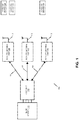
FIG. 1 is a block diagram of one exemplary embodiment of a distributed antenna system (DAS) 100 in which the improved remote antenna unit technology described here can be used. Although the improved remote antenna unit technology is described here in connection with theDAS 100 shown inFIG. 1 , it can be used in other DAS, repeater, or distributed base station products and systems. - The DAS 100 is used to distribute bi-directional wireless communications between one or
more base stations 102 and one or more wireless devices 104 (for example, mobile telephones, mobile computers, and/or combinations thereof such as personal digital assistants (PDAs) and smartphones). In the exemplary embodiment shown inFIG. 1 , theDAS 100 is used to distribute a plurality of bi-directional radio frequency bands. Also, each such radio frequency band is typically used to communicate multiple logical bi-directional RF channels. - The techniques described here are especially useful in connection with the distribution of wireless communications that use licensed radio frequency spectrum, such as cellular radio frequency communications. Examples of such cellular RF communications include cellular communications that support one or more of the second generation (2G), third generation (3G), and fourth generation (4G) Global System for Mobile communication (GSM) family of telephony and data specifications and standards, one or more of the second generation (2G), third generation (3G), and fourth generation (4G) Code Division Multiple Access (CDMA) family of telephony and data specifications and standards, and/or the WIMAX family of specification and standards. In the particular exemplary embodiment described here in connection with
FIG. 1 , theDAS 100 is configured to handle two cellular bi-directional radio frequency bands. In other embodiments, theDAS 100, and the improved remote antenna unit technology described here, are used with wireless communications that make use of unlicensed radio frequency spectrum such as wireless local area networking communications that support one or more of the IEEE 802.11 family of standards. In other embodiments, combinations of licensed and unlicensed radio frequency spectrum are distributed. - In the exemplary embodiment described here in connection with
FIG. 1 , theDAS 100 is configured to distribute wireless communications that use frequency division duplexing to implement the logical bi-directional RF bands. In other embodiments, theDAS 100 is configured to communicate at least some wireless communications that use other duplexing techniques (such as time division duplexing, which is used, for example, in some WIMAX implementations). - Since the
DAS 100 is configured to use frequency division duplexing in this exemplary embodiment, each of the bi-directional radio frequency bands distributed by theDAS 100 includes a separate radio frequency band for each of two directions of communications. One direction of communication is from thebase station 102 to awireless device 104 and is referred to here as the "downstream" or "downlink" direction. The other direction of communication is from thewireless device 104 to thebase station 102 and is referred to here as the "upstream" or "uplink" direction. Each of the distributed bi-directional radio frequency bands includes a "downstream" band in which downstream RF channels are communicated for that bi-directional radio frequency band and an "upstream" band in which upstream RF channels are communicated for that bi-directional radio frequency band. The downstream and upstream bands for a given bi-directional radio frequency band need not be, and typically are not, contiguous. - In the exemplary embodiment shown in
FIG. 1 , theDAS 100 includes ahost unit 106 and one or moreremote antenna units 108. TheDAS 100 shown inFIG. 1 uses onehost unit 106 and threeremote antenna units 108, though it is to be understood that other numbers ofhost units 106 and/orremote antenna units 108 can be used. - The
host unit 106 is communicatively coupled to the one ormore base stations 102 either directly (for example, via one or more coaxial cable connections) or indirectly (for example, via one or more donor antennas and one or more bidirectional amplifiers). - In the exemplary embodiment shown in
FIG. 1 , thehost unit 106 is communicatively coupled to eachremote antenna units 108 over a transport communication medium or media. The transport communication media can be implemented in various ways. For example, the transport communication media can be implemented using respective separate point-to-point communication links, for example, where respective optical fiber or copper cabling is used to directly connect thehost unit 106 to eachremote antenna unit 108. One such example is shown inFIG. 1 , where thehost unit 106 is directly connected to eachremote antenna unit 108 using a respectiveoptical fiber 110. Also, in the embodiment shown inFIG. 1 , a singleoptical fiber 110 is used to connect thehost unit 106 to eachremote antenna unit 108, where wave division multiplexing (WDM) is used to communicate both downstream and upstream signals over the singleoptical fiber 110. In other embodiments, thehost unit 106 is directly connected to eachremote antenna unit 108 using more than one optical fiber (for example, using two optical fibers, where one optical fiber is used for communicating downstream signals and the other optical fiber is used for communicating upstream signals). Also, in other embodiments, thehost unit 106 is directly connected to one or more of theremote antenna units 108 using other types of communication media such a coaxial cabling (for example, RG6, RG11, or RG59 coaxial cabling), twisted-pair cabling (for example, CAT-5 or CAT-6 cabling), or wireless communications (for example, microwave or free-space optical communications). - The transport communication media can also be implemented using shared point-to-multipoint communication media in addition to or instead of using point-to-point communication media. One example of such an implementation is where the
host unit 106 is directly coupled to an intermediary unit (also sometimes referred to as an "expansion" unit), which in turn is directly coupled to multipleremote antenna units 108. One example of such aDAS 600 is shown inFIG. 6 , where thehost unit 106 is directly connected to anexpansion unit 614, which in turn is directly connected to the multipleremote antenna units 108. Another example of a shared transport implementation is where thehost unit 106 is coupled to the remote antenna units using an Internet Protocol (IP) network. - Each
remote antenna unit 108 includes or is coupled to at least oneantenna 112 via which theremote antenna unit 108 receives and radiates radio frequency signals (as described in more detail below). - In general, downstream RF signals transmitted by the base station 102 (also referred to here as "downstream RF signals") are received at the
host unit 106. The downstream RF signals include both of the downstream frequency bands distributed by theDAS 100. In the exemplary embodiment shown inFIG. 1 , the downstream RF signals for each downstream frequency band are received on a respective downstream port of thehost unit 106. Thehost unit 106 then generates a digital representation of the downstream RF signals for each downstream frequency band. In one implementation of such an embodiment, thehost unit 106 is configured to down-convert the downstream RF signals for each downstream frequency band to a respective lower frequency band (also referred to here as an "intermediate frequency" band or "IF" band). Thehost unit 106 then digitizes the resulting downstream IF signals for each downstream band, which produces digital samples of the downstream IF signals (also referred to here as "downstream digital IF data"). These digital samples can be in the form of real samples or pairs of complex samples (having an in-phase (I) component and a quadrature (Q) component). - The
host unit 106 then frames the downstream digital IF data for the downstream frequency bands together (along with appropriate overhead data) and communicates the frames to each of theremote antenna units 108 over the respectiveoptical fibers 110. The downstream signal that is communicated to eachremote antenna unit 108 is also referred to here as a "downstream transport signal". In this embodiment, the downstream transport signal that thehost unit 106 generates for eachremote antenna unit 108 is an optical signal that is produced by optically modulating a downstream optical carrier with the downstream framed data (which contains the downstream digital IF data for the downstream frequency bands). - Each
remote antenna unit 108 receives the downstream transport signal that is communicated to thatremote antenna unit 108 over a respectiveoptical fiber 110. In general, eachremote antenna unit 108 demodulates the optical downstream transport signal (or otherwise performs an optical-to-electrical (O/E) process) in order to recover the downstream framed data transmitted by thehost unit 106. Theremote antenna unit 108 then extracts the downstream digital IF data for each of the downstream frequency bands. - In the embodiment described here in connection with
FIG. 1 , eachremote antenna unit 108, for each downstream frequency band, uses digital filtering techniques and/or digital signal processing on the downstream digital IF data for that downstream frequency band in order to apply one or more of the following: pre-distortion to compensate for any non-lineararities in the downstream signal path and phase and/or amplitude changes for beam forming or antenna steering. Then, for each downstream frequency band, the resulting digital IF data is applied to a digital-to-analog converter to produce a downstream analog IF signal for that downstream frequency band. The analog IF signal for each downstream frequency band is then up-converted to the appropriate RF frequency band and band-pass filtered to remove any unwanted harmonics and any other unwanted signal components. Then, the resulting analog RF signal for each downstream frequency band is power amplified and is ready to be radiated from at least oneantenna 112 associated with theremote antenna unit 108. Various antenna configurations can be used and are described below in connection withFIGS. 2-5 . - In general, in the upstream direction, upstream RF signals for each upstream frequency band distributed by the
DAS 100 are received on at least oneantenna 112 at eachremote antenna unit 108. Eachremote antenna unit 108 then generates a digital representation of the upstream RF signals for each upstream frequency band. In one implementation of such an embodiment, theremote antenna unit 108 is configured to down-convert the upstream RF signals for each upstream frequency band to a respective IF band. Eachremote antenna unit 108 then digitizes the resulting upstream IF signals for each downstream band, which produces digital samples of the upstream IF signals (also referred to here as "upstream digital IF data"). These digital samples can be in the form of real samples or pairs of complex samples (having an in-phase (I) component and a quadrature (Q) component). - Each
remote antenna unit 108, for each upstream frequency band, uses digital filtering techniques and/or digital signal processing on the upstream digital IF data for that upstream frequency band in order to apply one or more of the following: post-distortion to compensate for any non-lineararities in the upstream signal path, phase and/or amplitude changes for beam forming or antenna steering, and self-interference and distortion suppression. - Each
remote antenna unit 108 then frames the resulting processed upstream digital IF data for the upstream frequency bands together (along with appropriate overhead data) and communicates the frames to hostunit 106 over a respectiveoptical fiber 110. The upstream signal that is communicated to hostunit 106 is also referred to here as an "upstream transport signal". In this embodiment, the upstream transport signal that eachremote antenna unit 108 generates is an upstream optical signal that is produced by optically modulating an upstream optical carrier with the upstream framed data (which contains the upstream digital IF data for the upstream frequency bands). - The
host unit 106 receives the upstream transport signals that are communicated from all of theremote antenna units 108 over respectiveoptical fibers 110. - The
host unit 106 does the following for each of theremote antenna units 108 from which it receives signals. Thehost unit 106 demodulates the optical upstream transport signal (or otherwise performs an optical-to-electrical (O/E) process) in order to recover the upstream framed data transmitted by eachremote antenna unit 108. Thehost unit 106 then extracts the upstream digital IF data for each of the upstream frequency bands. - For each of the upstream frequency bands, the
host unit 106 digitally combines the upstream digital IF data received from all of theremote antenna units 108. This digital combining is performed by synchronizing the digital samples received from all of theremote antenna units 108 and then adding together (that is, digitally summing) the digital samples received from all of theremote antenna units 108 for each sample period. Appropriate overflow control is used to keep the resulting sum within a desired bit resolution. The resulting combined upstream digital IF data for each upstream frequency band is then applied to a respective digital-to-analog converter to produce an upstream analog IF signal for that upstream frequency band. - The resulting combined upstream analog IF signal for each upstream frequency band is then up-converted back to the original upstream RF frequency and band-pass filtered to remove any unwanted harmonics and any other unwanted signal components. The resulting upstream analog RF signal for each upstream frequency band is supplied to the base stations 102 (for example, over a respective upstream port of the host unit 106).
- In this way, RF signals transmitted and received by the
base station 102 are distributed by theDAS 100 and the resulting coverage area of thebase station 102 can be expanded. - In some embodiments of the
DAS 100, asingle antenna 112 is used to both radiate (transmit) downstream RF signals and to receive upstream RF signals. Conventionally, when a single antenna is used for both transmitting downstream RF signals and receiving upstream RF signals, a duplexer is used to separate and isolate the received upstream RF signals from the transmitted downstream RF signals. When the transmitted downstream RF signals are amplified to the relatively high output power levels typically used in outdoor DAS systems (for example, 10 Watts), a high-power duplexer (such as a relatively large and costly cavity duplexer) has historically been used in order to prevent the transmitted downstream RF signals from inundating the components in the (receive) upstream signal paths with out-of-band power, which can cause distortion and interference in the signals produced in the upstream single paths. The use of high-power duplexers can add to the cost and size of theremote antenna unit 108. Also, the cost and size increase associated with conventional high-power duplexers is multiplied in applications wheremany antennas 112 are used (for example, in Multiple Input/Multiple Output (MIMO) or antenna array applications). -
FIGS. 2-5 illustrate various strategies for dealing with duplexing in aremote antenna unit 108 -
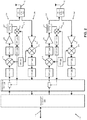
FIG. 2 is a block diagram of one embodiment of aremote antenna unit 200. Theremote antenna unit 200 is described here as being implemented for use in theDAS 100 described above in connection withFIG. 1 . - The
remote antenna unit 200 includes atransport interface 202 that is coupled to the respectiveoptical fiber 110 that is connected to thatremote antenna unit 200. Thetransport interface 202 includes an optical demodulator that demodulates the optical downstream transport signal received on theoptical fiber 110 from thehost unit 106 in order to recover the downstream framed data transmitted by thehost unit 106. Thetransport interface 202 also includes a deframer or demultiplexer to extract the downstream digital IF data for each of the downstream frequency bands from the downstream framed data. - The
remote antenna unit 200 includes one or moredownstream signal branches 204 and one or moreupstream signal branches 206. In the exemplary embodiment shown inFIG. 2 , eachdownstream signal branch 204 is used to process a respective one of the downstream frequency bands handled by theremote antenna unit 200. Similarly, eachupstream signal branch 206 is used to process a respective one of the upstream frequency bands handled by theremote antenna unit 200. - The
remote antenna unit 200 also includes aprocessing unit 208 that, in the exemplary embodiment shown inFIG. 2 , filters the downstream digital IF data for each downstream frequency band. This filtering is done in order to pre-distort the downstream digital IF data for each downstream frequency band in order to compensate for any non-lineararities in the associateddownstream signal branch 204. Eachdownstream signal branch 204 includes afeedback path 210 by which a digitized version of the downstream RF signal that is transmitted for thatdownstream signal branch 204 is fed back to theprocessing unit 208. Eachfeedback path 210 includes arespective RF coupler 227 to extract a portion of the downstream RF signal transmitted for thatdownstream signal branch 204, adownconverter 212 to downconvert the extracted downstream RF signal, a band-pass filter 213 to remove any unwanted harmonics and any other unwanted signal components, and an analog-to-digital converter (ADC) 214 to digitize the feedback signal. - In the exemplary embodiment shown in
FIG. 2 , theprocessing unit 208 uses the data provided on eachfeedback path 210 to adapt the pre-distortion that is applied to the downstream digital IF data for eachdownstream signal branch 204 in response to changes in thedownstream signal branch 204. - Each
downstream signal branch 204 includes a respective digital-to-analog converter (DAC) 216. TheDAC 216 in eachdownstream signal branch 204 is used to convert the pre-distorted digital IF data output by theprocessing unit 208 to a respective downstream analog IF signal for the corresponding downstream frequency band. Eachdownstream signal branch 204 also includes anupconverter 218 that up-converts the analog IF signal for the respective downstream frequency band to the appropriate RF frequency band. Theremote antenna unit 200 includes arespective oscillator circuit 220 for eachdownstream signal branch 204. Eachoscillator circuit 220 is configured to phase lock a local clock signal to a reference clock and to produce one or mixing signals for use by theupconverter 218 in thatdownstream signal branch 204 and for thedownconverter 212 in thefeedback path 210. - Each
downstream signal branch 204 also includes a respective band-pass filter 224 that removes any unwanted harmonics and any other unwanted signal components from the downstream analog RF signal output by theupconverter 218. - Each
downstream signal branch 204 also includes arespective power amplifier 226 that amplifies the downstream analog RF signal produced in thatdownstream signal branch 204. In the particular embodiment described here in connection withFIG. 2 , thepower amplifier 226 in eachdownstream signal branch 204 amplifies the corresponding downstream analog RF signal to a power level suitable for outdoor DAS applications (for example, 10 Watts). - In the exemplary embodiment shown in
FIG. 2 , theremote antenna unit 200 includes asingle antenna 112 for each bi-directional RF band handled by theremote antenna unit 200. That is, both the downstream analog RF signals and the associated upstream analog RF signals for a given bi-directional RF band are transmitted and received, respectively, using thesame antenna 112. Also, in the exemplary embodiment shown inFIG. 2 , arespective duplexer 230 is used to couple a respectivedownstream signal branch 204 and a respectiveupstream signal branch 206 to thecorresponding antenna 112. That is, the amplified downstream analog RF signals output by eachdownstream signal branch 204 are coupled to therespective antenna 112 via arespective duplexer 230. - As noted above, each
downstream signal branch 204 includes arespective feedback path 210 by which a digitized version of the downstream analog RF signals that are output for thatdownstream signal branch 204 are fed back to theprocessing unit 208. - In the exemplary embodiment shown in
FIG. 2 , RF signals received on eachantenna 112 are input to a respectiveupstream signal branch 206 via arespective duplexer 230. Theduplexer 230 passes only the RF signals for the upstream frequency band associated with thatupstream signal branch 206. Eachupstream signal branch 206 includes a respective low noise amplifier (LNA) 234 that amplifies the received upstream analog RF signals for the associated upstream frequency band. Eachupstream signal branch 206 also includes arespective downconverter 236 that down-converts the amplified analog upstream RF signals output by theLNA 234 in thatupstream signal branch 206 to the appropriate upstream IF band. Theoscillator circuit 220 associated with eachupstream signal branch 206 outputs the mixing signal used by thedownconverter 236 in thatupstream signal branch 206. - Each
upstream signal branch 206 also includes a respective band-pass filter 238 that removes any unwanted harmonics and any other unwanted signal components from the output of therespective downconverter 236. Eachupstream signal branch 206 also includes a respective analog-to-digital converter (ADC) 240 that digitizes the respective analog upstream IF signals output for thatupstream signal branch 206. - The output of each
ADC 240 is input to theprocessing unit 208. In the exemplary embodiment shown inFIG. 2 , theprocessing unit 208 filters the upstream digital IF data for each upstream frequency band. This filtering is done in order to post-distort the upstream digital IF data for each upstream frequency band in order to compensate for any non-lineararities in the associatedupstream signal branch 206. - The
transport interface 202 also includes a frame or multiplexer to combine the upstream digital IF data generated for each of the upstream frequency bands together (along with appropriate overhead data). Thetransport interface 202 also includes an optical modulator that generates an upstream optical signal for transmitting to thehost unit 106 on theoptical fiber 110. The optical modulator in the optical-to-electrical interface 202 generates the upstream optical signal by optically modulating an upstream optical carrier with the upstream framed data (which contains the upstream digital IF data for the upstream frequency bands). - The architecture of the exemplary embodiment of a
remote antenna unit 200 shown inFIG. 2 is conventional in nature in that it makes use of a relativelyhigh power amplifier 226 and a high-power duplexer 230 in each of thedownstream signal branches 204. The high-power duplexer 230 provides the required degree of isolation between the relatively high-power downstream RF signals transmitted from theremote antenna unit 200 and the upstream RF signals received on eachsuch antenna 112 and prevents the transmitted downstream RF signals from inundating the components in the (receive)upstream signal paths 206 with out-of-band power. As noted above, the use of a high-power duplexer (such as a cavity duplexer) can add to the cost and size of theremote antenna unit 200. Also, the cost and size increase associated with conventional high-power duplexers is multiplied in applications wheremany antennas 112 are used (for example, in MIMO or antenna array applications). -
FIG. 3 is a block diagram another exemplary embodiment of aremote antenna unit 300. Theremote antenna unit 300 is the same as theremote antenna unit 200 shown inFIG. 2 except as described below. For ease of explanation, those components ofremote antenna unit 300 that have corresponding components in theremote antenna unit 200 are referenced inFIG. 3 (and in the following description thereof) with the same reference numerals as used inFIG. 2 for those components, though the components may operate in a slightly different manner. - In the embodiment shown in
FIG. 3 , a low-power duplexer 230 is used to couple eachdownstream signal branch 204 and its associatedupstream signal branch 206 to its associatedantenna 112. However, since the downstream RF signals output by eachdownstream signal branch 204 are still transmitted at a relatively high power, the low-power duplexer 230 may not by itself provide sufficient isolation between the downstream RF signals transmitted from theremote antenna unit 300 and the received upstream RF signals. To address this issue, the digitized versions of the downstream RF signals that are fed back to the processing unit 208 (for the pre-distortion processing) are also used to suppress any self-interference caused by the transmitted downstream RF signals. This is done by digitally "subtracting" or "cancelling" the transmitted downstream RF signals from the upstream IF data that is otherwise produced in thatupstream signal branch 206. Typically, this is done after the post-distortion filtering has been performed. Moreover, the distortion caused by the components in theupstream signal branch 206 being inundated with out-of-band power due to the transmitted downstream RF signals can also be modeled and cancelled in theprocessing unit 208 using digital signal processing techniques. The signal processing (for example, the self-interference and distortion suppression processing) that is performed for eachupstream signal branch 206 can be performed using the digitized version of the downstream analog RF signals output by one or more of thedownstream signal branches 204. The self-interference and distortion suppression processing that is performed for eachupstream signal branch 206 can be performed using the digitized version of the downstream RF signal produced by only the corresponding downstream signal branch 204 (for example, to reduce the processing complexity) or using the digitized version of the downstream RF signal produced by the correspondingdownstream signal branch 204 as well those produced by one or more of the other downstream signal branches 204 (for example, where the downstream RF signals produced by the one or more otherdownstream signal branches 204 also interfere with or distort the upstream RF signal produced by that upstream signal branch 206). - The self-interference and distortion suppression performed by the
processing unit 208, in combination with the low-power duplexer 230, is able, in some implementations, to provide sufficient isolation between the downstream RF signals and the received upstream RF signals in a more compact and cost-effective manner. -
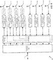
FIG. 4 is block diagram of another exemplary embodiment of aremote antenna unit 400. Theremote antenna unit 400 is the same as theremote antenna unit 200 shown inFIG. 2 except as described below. For ease of explanation, those components ofremote antenna unit 400 that have corresponding components in theremote antenna unit 200 are referenced inFIG. 4 (and in the following description thereof) with the same reference numerals as used inFIG. 2 for those components though the components may operate in a slightly different manner. - In the embodiment shown in
FIG. 4 , instead of using aduplexer 230 to couple eachdownstream signal branch 204 and its correspondingupstream signal branch 206 to a single, sharedantenna 112, eachdownstream signal branch 204 has its own respective antenna 112-TX, and eachupstream signal branch 206 has its own respective antenna 112-RX. Noduplexers 230 are used. By using separate transmit and receive antennas 112-TX and 112-RX that are spatially isolated from one another, isolation can be provided between the downstream RF signals transmitted from eachdownstream signal branch 204 and the received upstream RF signals. However, in some applications, it may not possible to arrange the transmit and receive antennas 112-TX and 112-RX so as to provide sufficient isolation between the downstream RF signals transmitted from eachdownstream signal branch 204 and the received upstream RF signals based solely on spatial isolation of the antennas 112-TX and 112-RX. The exemplary embodiment shown inFIG. 4 is directed to such a situation. - In the exemplary embodiment shown in
FIG. 4 , as with the exemplary embodiment shown inFIG. 3 , the digitized versions of the downstream RF signals that are fed back to theprocessing unit 208 and used for in suppressing any self-interference caused by the transmitted downstream RF signals. Moreover, as with the exemplary embodiment shown inFIG. 3 , the distortion caused by the components in theupstream signal branch 206 being inundated with out-of-band power due to the transmitted downstream RF signals can also be modeled and cancelled in theprocessing unit 208 using digital signal processing techniques. - In this way, the self-interference and distortion suppression performed by the
processing unit 208, in combination with the isolation provided by the arrangement of the transmit and receive antennas 112-TX and 112-RX, may be able to provide sufficient isolation between the downstream RF signals and the upstream RF signals in some situations where the isolation provided by the spatial arrangement of the separate transmit and receive antennas 112-TX and 112-RX is unable to do so by itself. - Also, in the exemplary embodiment shown in
FIG. 4 , to reduce the likelihood that out-of-band power from the transmitted downstream RF signals inundate the components in theupstream signal branches 206, eachupstream signal branch 206 includes a band-rejection filter (BRF) 402 that rejects the frequency bands associated with the downstream RF signals transmitted by theremote antenna unit 400. The use of band-reject filters 402 may not be necessary in all situations. In some embodiments, a transmit band pass filter is applied after thecoupler 227 and before theantenna 112 in each of thedownstream signal branches 204. - The self-interference and distortion suppression described above can also be used in MIMO or antenna array applications. One such example is illustrated in
FIG. 5. FIG. 5 is a block diagram of another exemplary embodiment of aremote antenna unit 500. Theremote antenna unit 500 is the same as theremote antenna unit 200 shown inFIG. 2 except as described below. For ease of explanation, those components ofremote antenna unit 500 that have corresponding components in theremote antenna unit 200 are referenced inFIG. 5 (and in the following description thereof) with the same reference numerals as used inFIG. 2 for those components though the components may operate in a slightly different manner. Moreover,FIG. 5 has been simplified for ease of explanation. - The
remote antenna unit 500 is similar to the one shown inFIG. 4 except that theremote antenna unit 400 has been modified for a MIMO or antenna array application where there is greater number of transmit and receive antennas 112-TX and 112-RX used. In the exemplary embodiment shown inFIG. 5 , as with the exemplary embodiment shown inFIG. 4 , the digitized versions of the downstream RF signals that are fed back to the processing unit 208 (for the pre-distortion processing) are also fed back to theprocessing unit 208 for use in providing self-interference and distortion suppression. The self-interference and distortion suppression processing that is performed for eachupstream signal branch 206 can be performed using the digitized version of the downstream RF signal produced by only the corresponding downstream signal branch 204 (for example, to reduce the processing complexity) or using the digitized version of the downstream RF signal produced by the correspondingdownstream signal branch 204 as well those produced by one or more of the other downstream signal branches 204 (for example, where the downstream RF signals produced by the one or more otherdownstream signal branches 204 also interfere with or distort the upstream RF signal produced by that upstream signal branch 206). In the embodiment shown inFIG. 5 , the output of eachdownstream signal branch 204 is coupled to a respective transmit antenna 112-TX via arespective isolator 510, reduces so-called "reverse intermodulaton" where the transmitted signal from a first transmit antenna 112-TX mixes with the signals transmitted by a second transmit antenna 112-TX to result in undesirable interference components. Theisolator 510 may not be necessary in all cases, depending on, for example, the linearity of the final stages of thedownstream signal branch 206. - Also, by using numerous transmit and receive antennas, the output power levels of the downstream RF signals transmitted from each
remote antenna unit 108 can be reduced. This should result in a reduction in the amount of self-interference or distortion caused by the transmitted downstream RF signals leaking into to the (receive)upstream signal branches 206 and/or the components in the (receive)upstream signal branches 206 being inundated with out-of-band power. As a result, in some applications, the self-interference and distortion suppression techniques described above and the use of spatially isolated transmit and receive antennas 112-TX and 112-RX, may be sufficient to obviate the need for duplexers. - More generally, the self-interference and distortion suppression techniques described above can be used to provide an additional amount of separation and isolation between the received upstream RF signals and the transmitted downstream RF signals. This additional amount of separation and isolation may be usefully applied in applications where the spatial isolation of the separate transmit and receive antennas is less than optimal (for example, due to the need to achieve an omni-directional antenna structure or due to packaging concerns). One example of where this may be the case is in an omni-directional antenna array having multiple transmit and receive antennas formed on multiple surfaces of a cube structure. Other examples of antenna modules having possibly less than optimal arrangements of transmit and receive antennas where the self-interference and distortion suppression techniques described here may be used are described in
U.S. Provisional Patent Application Serial No. 61/ 495,235, filed on June 9, 2011 - In addition to the digital self-interference and distortion suppression techniques described above, analog self-interference suppression techniques can be used in which an analog version of each transmitted downstream RF signal is delayed by 180 degrees and subtracted from the received upstream RF signals. One example of how such analog self-interference suppression can be performed is described in
U.S. Patent Application Serial No. 13/073,111, filed on March 28, 2011 , and titled "EXTERNAL MOUNTED AMPLIFIERS WITH ACTIVE INTERFERENCE CANCELATION USING DIVERSITY ANTENNAS", which is hereby incorporated herein by reference. - Although the embodiments shown in
FIGS. 1-5 were described as being implemented in a particular type of digital DAS, it is to be understood that the self-interference and distortion suppression techniques described here can be used in other types of DAS, repeater, and distributed base station systems and products. For example, the self- interference and distortion suppression techniques described here can be used in a digital DAS where the signals distributed between the host unit and the remote antenna units are digital baseband data. Examples of digital baseband formats are the formats described in the Open Base Station Architecture Initiative (OBSAI) and Common Public Radio Interface (CPRI) family of standards and specifications. Also, the self-interference and distortion suppression techniques described here can be used in analog DAS and repeater products, in which case analog versions of the transmitted downstream RF signals would be fed back and also used in each of the upstream signal branches (in a manner similar to what is described in the previous paragraph). - The components of the
feedback path 210 can be used to provide digitized versions of signals external to theremote antenna unit 108 to theprocessing unit 208. For example, one or more of thefeedback paths 210 includes a switch to selectively couple the input of thatfeedback path 210 to either thecoupler 227 or an antenna 112 (either directly or through a duplexer). In the former case (that is, when the switch couples the input of thatfeedback path 210 to the coupler 227), a digitized version of the downstream RF signals for thatdownstream signal branch 204 are fed back to theprocessing unit 208 for the pre-distortion and self-interference and distortion suppression processing described above. - In the latter case (that is, when the switch couples the input of that
feedback path 210 to the antenna 112), signals received via theantenna 112 can be fed back to thesignal processing unit 208 instead of a digitized version of the downstream RF signals. This can be done, for example, if aparticular feedback path 210 is not needed for the pre-distortion and self-interference and distortion suppression processing described above (for example, because the particular algorithms used for such processing have converged to a stable state or because that particulardownstream signal branch 204 is not being used at that time). These fed back signals can used to determine the identity and level of co-channel cells or adjacent-channel cells. - The configuration provided in this latter case can be used for other purposes. For example, a specific sequence or pattern can be radiated from each remote antenna unit in a DAS or from each downstream signal branch 204 (for example, in the LTE Physical Downlink Shared Channel (PDSCH) or the HSPA PDSCH). The path-loss between the different remote antenna units or signal
branches 204 can be measured and used to control the base station, remote antenna unit, ordownstream signal path 204, for example, for deployment or other purposes or when choosing which unit or path to incorporate in a joint scheduling, joint beamforming or joint MIMO transmission. -
- Example 1 includes a distributed antenna system comprising: a host unit; and at least one remote antenna unit that is communicatively coupled to the host unit; wherein the host unit is configured to communicate a downstream transport signal from the host unit to the remote antenna unit; wherein the remote antenna unit to which the downstream transport signal is communicated uses the downstream transport signal to generate a downstream radio frequency signal for radiation from an antenna associated with the remote antenna unit; wherein the remote antenna unit is configured to communicate an upstream transport signal from the remote antenna unit to the host unit, wherein the upstream transport signal is generated from a received upstream radio frequency signal received at the remote antenna unit; and wherein the remote antenna unit is configured to perform self-interference suppression processing in an upstream signal path using, as an input thereto, a feedback signal derived from the downstream radio frequency signal radiated from the antenna.
- Example 2 includes the distributed antenna system of Example 1, wherein the remote antenna system is configured to receive the received upstream radio frequency signal using the same antenna used to radiate the downstream radio frequency signal.
- Example 3 includes the distributed antenna system of Example 2, wherein the remote antenna system further comprises a duplexer coupled to the antenna.
- Example 4 includes the distributed antenna system of Example 3, wherein the duplexer comprises a low-power duplexer.
- Example 5 includes the distributed antenna system of Example 4, wherein the low-power duplexer comprises a mobile handset duplexer.
- Example 6 includes any of the distributed antenna systems of Examples 1-5, wherein the remote antenna system is configured to radiate the downstream radio frequency signal from a first antenna and wherein the remote antenna system is configured to receive the received upstream radio frequency signal using a second antenna.
- Example 7 includes the distributed antenna system of Example 6, wherein the remote antenna system does not use a duplexer.
- Example 8 includes any of the distributed antenna systems of Examples 1-7, wherein the downstream transport signal comprises a digitized version of an original downstream radio frequency signal received at the host unit and wherein the upstream transport signal comprises a digitized version of the received upstream radio frequency signal received at the remote antenna unit.
- Example 9 includes any of the distributed antenna systems of Examples 1-8, wherein at least one of the downstream transport signal and the upstream transport signal comprises digital baseband data.
- Example 10 includes the distributed antenna system of Example 9, wherein the digital baseband data comprises at least of one OBSAI digital baseband data or CPRI digital baseband data.
- Example 11 includes any of the distributed antenna systems of Examples 1-10, wherein the downstream transport signal comprises an analog version of an original downstream radio frequency signal received at the host unit and wherein the upstream transport signal comprises an analog version of the received upstream radio frequency signal received at the remote antenna unit.
- Example 12 includes any of the distributed antenna systems of Examples 1-11, wherein a plurality of antennas is coupled to the remote antenna unit.
- Example 13 includes any of the distributed antenna systems of Examples 1-12, wherein the distributed antenna system is configured to distribute MIMO signals. Example 14 includes any of the distributed antenna systems of Examples 1-13, wherein the remote antenna unit comprises a feedback path and a switch to selectively couple either the downstream radio frequency signal or an external radio frequency signal to an input of the feedback path.
- Example 15 includes a remote antenna unit for use in a distributed antenna system, the remote antenna unit comprising: a transport interface to communicatively couple the remote antenna unit to a host unit included in the distributed antenna system and to receive a downstream transport signal from the host unit; a processing unit coupled to the transport interface; at least one downstream signal branch; and at least one upstream signal branch; wherein the processing unit and downstream signal branch are configured to use the downstream transport signal to generate a downstream radio frequency signal for radiation from an antenna associated with the remote antenna unit; wherein the transport interface is configured to communicate an upstream transport signal from the remote antenna unit to the host unit, wherein the processing unit and the upstream signal branch are configured to generate an upstream signal from a received upstream radio frequency signal received at the remote antenna unit, wherein the transport interface uses the upstream signal to generate the upstream transport signal; and wherein the processing unit is configured to perform self-interference suppression processing on the upstream signal using, as an input thereto, a feedback signal derived from the downstream radio frequency signal radiated from the antenna.
- Example 16 includes the remote antenna unit of Example 15, wherein the remote antenna system is configured to receive the received upstream radio frequency signal using the same antenna used to radiate the downstream radio frequency signal.
- Example 17 includes the remote antenna unit of Example 16, wherein the remote antenna system further comprises a duplexer coupled to the antenna.
- Example 18 includes the remote antenna unit of Example 17, wherein the duplexer comprises a low-power duplexer.
- Example 19 includes the remote antenna unit of Example 18, wherein the low-power duplexer comprises a mobile handset duplexer.
- Example 20 includes any of the remote antenna units of Examples 15-19, wherein the remote antenna system is configured to radiate the downstream radio frequency signal from a first antenna and wherein the remote antenna system is configured to receive the received upstream radio frequency signal using a second antenna.
- Example 21 includes the remote antenna unit of Example 20, wherein the remote antenna system does not use a duplexer.
- Example 22 includes any of the remote antenna units of Examples 15-21, wherein the downstream transport signal comprises a digitized version of an original downstream radio frequency signal received at the host unit and wherein the upstream transport signal comprises a digitized version of the received upstream radio frequency signal received at the remote antenna unit.
- Example 23 includes any of the remote antenna units of Examples 15-22, wherein at least one of the downstream transport signal and the upstream transport signal comprises digital baseband data.
- Example 24 includes the remote antenna unit of Example 23, wherein the digital baseband data comprises at least of one OBSAI digital baseband data or CPRI digital baseband data.
- Example 25 includes any of the remote antenna units of Examples 15-24, wherein the downstream transport signal comprises an analog version of an original downstream radio frequency signal received at the host unit and wherein the upstream transport signal comprises an analog version of the received upstream radio frequency signal received at the remote antenna unit.
- Example 26 includes any of the remote antenna units of Examples 15-25, wherein a plurality of antennas is coupled to the remote antenna unit.
- Example 27 includes any of the remote antenna units of Examples 15-26, wherein the remote antenna unit is configured to distribute MIMO signals. Example 28 includes any of the remote antenna units of Examples 15-27, wherein the remote antenna unit comprises a feedback path and a switch to selectively couple either the downstream radio frequency signal or an external radio frequency signal to an input of the feedback path.
- Example 29 includes a remote antenna unit for use in a distributed antenna system, the remote antenna unit comprising: a transport interface to communicatively couple the remote antenna unit to a host unit included in the distributed antenna system and to receive a downstream transport signal from the host unit; a processing unit coupled to the transport interface; at least one downstream signal branch; and at least one upstream signal branch; wherein the processing unit and downstream signal branch are configured to use the downstream transport signal to generate a downstream radio frequency signal for radiation from an antenna associated with the remote antenna unit; wherein the transport interface is configured to communicate an upstream transport signal from the remote antenna unit to the host unit, wherein the processing unit and the upstream signal branch are configured to generate an upstream signal from a received upstream radio frequency signal received at the remote antenna unit, wherein the transport interface uses the upstream signal to generate the upstream transport signal; and wherein the processing unit is configured to pre-distort an input signal to the downstream signal branch for non-linearities in the downstream signal branch using a feedback signal derived from the downstream radio frequency signal radiated from the antenna.
- Example 30 includes the remote antenna unit of Example 29, wherein the remote antenna system further comprises a duplexer coupled to the antenna.
- Example 31 includes the remote antenna unit of Example 30, wherein the duplexer comprises a high-power duplexer. Example 32 includes any of the remote antenna units of Examples 29-31, wherein the remote antenna unit comprises a feedback path and a switch to selectively couple either the downstream radio frequency signal or an external radio frequency signal to an input of the feedback path.
- A number of embodiments have been described. Nevertheless, it will be understood that various modifications to the described embodiments may be made without departing from the spirit and scope of the claimed invention.
- The invention also comprises the following clauses:
- 1. A distributed antenna system comprising:
- a host unit; and
- at least one remote antenna unit that is communicatively coupled to the host unit;
- wherein the host unit is configured to communicate a downstream transport signal from the host unit to the remote antenna unit;
- wherein the remote antenna unit to which the downstream transport signal is communicated uses the downstream transport signal to generate a downstream radio frequency signal for radiation from an antenna associated with the remote antenna unit;
- wherein the remote antenna unit is configured to communicate an upstream transport signal from the remote antenna unit to the host unit, wherein the upstream transport signal is generated from a received upstream radio frequency signal received at the remote antenna unit; and
- wherein the remote antenna unit is configured to perform self-interference suppression processing in an upstream signal path using, as an input thereto, a feedback signal derived from the downstream radio frequency signal radiated from the antenna.
- 2. The distributed antenna system of
clause 1, wherein the remote antenna system is configured to receive the received upstream radio frequency signal using the same antenna used to radiate the downstream radio frequency signal. - 3. The distributed antenna system of clause 2, wherein the remote antenna system further comprises a duplexer coupled to the antenna.
- 4. The distributed antenna system of clause 3, wherein the duplexer comprises a low-power duplexer.
- 5. The distributed antenna system of clause 4, wherein the low-power duplexer comprises a mobile handset duplexer.
- 6. The distributed antenna system of
clause 1, wherein the remote antenna system is configured to radiate the downstream radio frequency signal from a first antenna and wherein the remote antenna system is configured to receive the received upstream radio frequency signal using a second antenna. - 7. The distributed antenna system of clause 6, wherein the remote antenna system does not use a duplexer.
- 8. The distributed antenna system of
clause 1, wherein the downstream transport signal comprises a digitized version of an original downstream radio frequency signal received at the host unit and wherein the upstream transport signal comprises a digitized version of the received upstream radio frequency signal received at the remote antenna unit. - 9. The distributed antenna system of
clause 1, wherein at least one of the downstream transport signal and the upstream transport signal comprises digital baseband data. - 10. The distributed antenna system of
clause 9, wherein the digital baseband data comprises at least of one OBSAI digital baseband data or CPRI digital baseband data. - 11. The distributed antenna system of
clause 1, wherein the downstream transport signal comprises an analog version of an original downstream radio frequency signal received at the host unit and wherein the upstream transport signal comprises an analog version of the received upstream radio frequency signal received at the remote antenna unit. - 12. The distributed antenna system of
clause 1, wherein a plurality of antennas is coupled to the remote antenna unit. - 13. The distributed antenna system of
clause 1, wherein the distributed antenna system is configured to distribute MIMO signals. - 14. The distributed antenna system of
clause 1, wherein the remote antenna unit comprises a feedback path and a switch to selectively couple either the downstream radio frequency signal or an external radio frequency signal to an input of the feedback path. - 15. A remote antenna unit for use in a distributed antenna system, the remote antenna unit comprising:
- a transport interface to communicatively couple the remote antenna unit to a host unit included in the distributed antenna system and to receive a downstream transport signal from the host unit;
- a processing unit coupled to the transport interface;
- at least one downstream signal branch; and
- at least one upstream signal branch;
- wherein the processing unit and downstream signal branch are configured to use the downstream transport signal to generate a downstream radio frequency signal for radiation from an antenna associated with the remote antenna unit;
- wherein the transport interface is configured to communicate an upstream transport signal from the remote antenna unit to the host unit, wherein the processing unit and the upstream signal branch are configured to generate an upstream signal from a received upstream radio frequency signal received at the remote antenna unit, wherein the transport interface uses the upstream signal to generate the upstream transport signal; and
- wherein the processing unit is configured to perform self-interference suppression processing on the upstream signal using, as an input thereto, a feedback signal derived from the downstream radio frequency signal radiated from the antenna.
- 16. The remote antenna unit of clause 15, wherein the remote antenna system is configured to receive the received upstream radio frequency signal using the same antenna used to radiate the downstream radio frequency signal.
- 17. The remote antenna unit of clause 16, wherein the remote antenna system further comprises a duplexer coupled to the antenna.
- 18. The remote antenna unit of clause 17, wherein the duplexer comprises a low-power duplexer.
- 19. The remote antenna unit of clause 18, wherein the low-power duplexer comprises a mobile handset duplexer.
- 20. The remote antenna unit of clause 15, wherein the remote antenna system is configured to radiate the downstream radio frequency signal from a first antenna and wherein the remote antenna system is configured to receive the received upstream radio frequency signal using a second antenna.
- 21. The remote antenna unit of clause 20, wherein the remote antenna system does not use a duplexer.
- 22. The remote antenna unit of clause 15, wherein the downstream transport signal comprises a digitized version of an original downstream radio frequency signal received at the host unit and wherein the upstream transport signal comprises a digitized version of the received upstream radio frequency signal received at the remote antenna unit.
- 23. The remote antenna unit of clause 15, wherein at least one of the downstream transport signal and the upstream transport signal comprises digital baseband data.
- 24. The remote antenna unit of clause 23, wherein the digital baseband data comprises at least of one OBSAI digital baseband data or CPRI digital baseband data.
- 25. The remote antenna unit of clause 15, wherein the downstream transport signal comprises an analog version of an original downstream radio frequency signal received at the host unit and wherein the upstream transport signal comprises an analog version of the received upstream radio frequency signal received at the remote antenna unit.
- 26. The remote antenna unit of clause 15, wherein a plurality of antennas is coupled to the remote antenna unit.
- 27. The remote antenna unit of clause 15, wherein the remote antenna unit is configured to distribute MIMO signals.
- 28. The remote antenna unit of clause 15, wherein the remote antenna unit comprises a feedback path and a switch to selectively couple either the downstream radio frequency signal or an external radio frequency signal to an input of the feedback path.
- 29. A remote antenna unit for use in a distributed antenna system, the remote antenna unit comprising:
- a transport interface to communicatively couple the remote antenna unit to a host unit included in the distributed antenna system and to receive a downstream transport signal from the host unit;
- a processing unit coupled to the transport interface;
- at least one downstream signal branch; and
- at least one upstream signal branch;
- wherein the processing unit and downstream signal branch are configured to use the downstream transport signal to generate a downstream radio frequency signal for radiation from an antenna associated with the remote antenna unit;
- wherein the transport interface is configured to communicate an upstream transport signal from the remote antenna unit to the host unit, wherein the processing unit and the upstream signal branch are configured to generate an upstream signal from a received upstream radio frequency signal received at the remote antenna unit, wherein the transport interface uses the upstream signal to generate the upstream transport signal; and
- wherein the processing unit is configured to pre-distort an input signal to the downstream signal branch for non-linearities in the downstream signal branch using a feedback signal derived from the downstream radio frequency signal radiated from the antenna.
- 30. The remote antenna unit of clause 29, wherein the remote antenna system further comprises a duplexer coupled to the antenna.
- 31. The remote antenna unit of clause 30, wherein the duplexer comprises a high- wherein the remote antenna unit comprises a feedback path and a switch to selectively couple either the downstream radio frequency signal or an external radio frequency signal to an input of the feedback path.
- 32. The remote antenna unit of clause 29, wherein the remote antenna unit comprises a feedback path and a switch to selectively couple either the downstream radio frequency signal or an external radio frequency signal to an input of the feedback path.
Claims (15)
- A distributed antenna system (200) comprising:a host unit (202) communicatively coupled to a base station (102), the host unit (202) configured to receive a first signal from the base station (102);a first remote antenna unit (204) communicatively coupled to the host unit (202), the first remote antenna unit (204) having a first antenna (208);wherein the base station (102) to which the distributed antenna system (200) is communicatively coupled is configured with a subscriber access timing window having a minimum allowed delay and a maximum allowed delay;wherein the distributed antenna system (200) is configured so that a first total delay between the host unit (202) and the first remote antenna unit (204) is equal to or greater than the minimum allowed delay; andwherein the first antenna (208) of the first remote antenna unit (204) is configured to communicate the first signal to a first subscriber unit, wherein a coverage area of communication from the first antenna (208) of the first remote antenna unit (204) becomes smaller as the first total delay increases.
- The distributed antenna system (200) of claim 1, wherein the first total delay comprises at least one of:a first inherent delay in the distributed antenna system (200) between the host unit (202) and the first remote antenna unit (204);a first propagation delay between the host unit (202) and the first remote antenna unit (204); anda first additional configurable delay.
- The distributed antenna system (200) of claim 1, wherein the first total delay comprises a first configurable delay.
- The distributed antenna system (200) of claim 1, wherein the first remote antenna unit (204) is communicatively coupled to the host unit (202) via a physical medium (206) or a wireless medium (206).
- The distributed antenna system (200) of claim 1, wherein the base station (102) is configured to output, and receive as input, respective digital baseband data; and
wherein the first signal is a digital baseband data signal. - The distributed antenna system (200) of claim 1, wherein the base station (102) is configured to output, and receive as input, radio frequency signals; and wherein the first signal is a radio frequency signal.
- The distributed antenna system (200) of claim 1, wherein the distributed antenna system (200) is coupled to multiple wireless service providers' networks and configured to distribute multiple services.
- The distributed antenna system (200) of claim 1, wherein the distributed antenna system (200) is configured for use in at least one of: in-building applications, outdoor applications, enterprise applications, public safety applications, and military applications.
- The distributed antenna system (200) of claim 1, further comprising groups of the remote antenna units that are configurable for local joint beamforming and/or joint transmission groups of cells.
- The distributed antenna system (200) of claim 1, further comprising:a second remote antenna unit (204A, 204B, 204C, 204D) communicatively coupled to the host unit (202), the second remote antenna unit (204A, 204B, 204C, 204D) having a second antenna (208A, 208B, 208C, 208D);wherein the distributed antenna system (200) is configured so that a second total delay between the host unit (202) and the second remote antenna unit (204A, 204B, 204C, 204D) is equal to or greater than the minimum allowed delay; andwherein the second antenna (208A, 208B, 208C, 208D) of the second remote antenna unit (204A, 204B, 204C, 204D) is configured to communicate the first signal to a second subscriber unit, wherein a second coverage area of communication from the second antenna (208A, 208B, 208C, 208D) of the second remote antenna unit (204A, 204B, 204C, 204D) becomes smaller as the second total delay increases.
- A method comprising:configuring a distributed antenna system (200) to have a first additional delay in addition to a first inherent delay of the distributed antenna system (200) between a host unit (202) and a first remote antenna unit (204);wherein the distributed antenna system (200) is communicatively coupled to a base station (102) configured with a subscriber access timing window having a minimum allowed delay and a maximum allowed delay;wherein a first total delay of the first additional delay and the first inherent delay of the distributed antenna system (200) is equal to or greater than the minimum allowed delay; andwherein a coverage area of communication from the first antenna (208) of the first remote antenna unit (204) becomes smaller as the first total delay increases.
- The method of claim 11, wherein the first inherent delay comprises at least one of a propagation delay between the host unit (202) and the first remote antenna unit (204).
- The method of claim 11, further comprising transporting signals from the base station (102) through the distributed antenna system (200) via a physical medium (206).
- The method of claim 11, further comprising communicating at least one of digital baseband data and radio frequency signals between the base station (102) and the host unit (202) of the distributed antenna system (200).
- The method of claim 11, further comprising:configuring a distributed antenna system (200) to have a second additional delay in addition to a second inherent delay of the distributed antenna system (200) between the host unit (202) and a second remote antenna unit (204A, 204B, 204C, 204D); andwherein a second total delay of the second additional delay and the second inherent delay of the distributed antenna system (200) is equal to or greater than the minimum allowed delay.
Priority Applications (1)
| Application Number | Priority Date | Filing Date | Title |
|---|---|---|---|
| EP20211340.3A EP3843285A1 (en) | 2011-06-13 | 2012-06-13 | Distributed antenna system architectures |
Applications Claiming Priority (3)
| Application Number | Priority Date | Filing Date | Title |
|---|---|---|---|
| US201161496548P | 2011-06-13 | 2011-06-13 | |
| PCT/US2012/042148 WO2012174047A2 (en) | 2011-06-13 | 2012-06-13 | Distributed antenna system architectures |
| EP12800117.9A EP2719093B1 (en) | 2011-06-13 | 2012-06-13 | Distributed antenna system architectures |
Related Parent Applications (1)
| Application Number | Title | Priority Date | Filing Date |
|---|---|---|---|
| EP12800117.9A Division EP2719093B1 (en) | 2011-06-13 | 2012-06-13 | Distributed antenna system architectures |
Related Child Applications (1)
| Application Number | Title | Priority Date | Filing Date |
|---|---|---|---|
| EP20211340.3A Division EP3843285A1 (en) | 2011-06-13 | 2012-06-13 | Distributed antenna system architectures |
Publications (1)
| Publication Number | Publication Date |
|---|---|
| EP3661321A1 true EP3661321A1 (en) | 2020-06-03 |
Family
ID=47357696
Family Applications (3)
| Application Number | Title | Priority Date | Filing Date |
|---|---|---|---|
| EP20151471.8A Withdrawn EP3661321A1 (en) | 2011-06-13 | 2012-06-13 | Distributed antenna system architectures |
| EP20211340.3A Pending EP3843285A1 (en) | 2011-06-13 | 2012-06-13 | Distributed antenna system architectures |
| EP12800117.9A Active EP2719093B1 (en) | 2011-06-13 | 2012-06-13 | Distributed antenna system architectures |
Family Applications After (2)
| Application Number | Title | Priority Date | Filing Date |
|---|---|---|---|
| EP20211340.3A Pending EP3843285A1 (en) | 2011-06-13 | 2012-06-13 | Distributed antenna system architectures |
| EP12800117.9A Active EP2719093B1 (en) | 2011-06-13 | 2012-06-13 | Distributed antenna system architectures |
Country Status (6)
| Country | Link |
|---|---|
| US (3) | US9748906B2 (en) |
| EP (3) | EP3661321A1 (en) |
| KR (1) | KR20140037912A (en) |
| CN (1) | CN103828259B (en) |
| CA (1) | CA2838740A1 (en) |
| WO (1) | WO2012174047A2 (en) |
Families Citing this family (225)
| Publication number | Priority date | Publication date | Assignee | Title |
|---|---|---|---|---|
| CN103229427B (en) | 2010-10-01 | 2016-08-03 | 康普技术有限责任公司 | Distributing antenna system for MIMO signal |
| US8818299B2 (en) | 2011-06-01 | 2014-08-26 | Andrew Llc | Broadband distributed antenna system with non-duplexer isolator sub-system |
| KR20140037912A (en) * | 2011-06-13 | 2014-03-27 | 에이디씨 텔레커뮤니케이션스 인코포레이티드 | Distributed antenna system architectures |
| EP3422589B1 (en) | 2012-02-02 | 2024-07-24 | CommScope Technologies LLC | Optimized telecommunications distribution system |
| US9450671B2 (en) * | 2012-03-20 | 2016-09-20 | Industrial Technology Research Institute | Transmitting and receiving apparatus and method for light communication, and the light communication system thereof |
| US9407004B2 (en) * | 2012-07-25 | 2016-08-02 | Tyco Electronics Corporation | Multi-element omni-directional antenna |
| EP2904831B1 (en) | 2012-10-05 | 2017-10-04 | Andrew Wireless Systems GmbH | Capacity optimization sub-system for distributed antenna system |
| CA2892508A1 (en) * | 2012-11-26 | 2014-05-30 | Adc Telecommunications, Inc. | Timeslot mapping and/or aggregation element for digital radio frequency transport architecture |
| US10009065B2 (en) | 2012-12-05 | 2018-06-26 | At&T Intellectual Property I, L.P. | Backhaul link for distributed antenna system |
| US9113347B2 (en) | 2012-12-05 | 2015-08-18 | At&T Intellectual Property I, Lp | Backhaul link for distributed antenna system |
| US9473187B2 (en) * | 2012-12-20 | 2016-10-18 | Cellco Partnership | Wireless radio extension using up- and down-conversion |
| KR102158392B1 (en) * | 2013-04-05 | 2020-09-22 | 엘에스전선 주식회사 | Distributed antenna system |
| KR20140089054A (en) * | 2013-01-02 | 2014-07-14 | 엘에스전선 주식회사 | Communication Repeating Apparatus and Communication Signal Repeating Method |
| US9432063B2 (en) | 2013-01-16 | 2016-08-30 | Huawei Technologies Co., Ltd. | Radio frequency signal transceiving and processing method, device, and base station system |
| CN103107966B (en) * | 2013-01-16 | 2016-03-30 | 华为技术有限公司 | Radiofrequency signal transmitting-receiving and the method processed, equipment and base station system |
| US9955361B2 (en) | 2013-02-26 | 2018-04-24 | Dali Systems Co., Ltd. | Method and system for WI-FI data transmission |
| US20170033869A1 (en) * | 2013-03-02 | 2017-02-02 | Westell, Inc. | Distributed antenna system having remote units with scanning receivers |
| US9467230B2 (en) * | 2013-03-02 | 2016-10-11 | Westell, Inc. | Distributed antenna system having high near far performance |
| JP6174167B2 (en) * | 2013-03-04 | 2017-08-02 | ケーエムダブリュ・インコーポレーテッド | Antenna sharing device for wireless connection node system in wireless communication network |
| CN104052531B (en) * | 2013-03-12 | 2018-01-12 | 华为技术有限公司 | Self interference signal clearing method and device |
| US9999038B2 (en) | 2013-05-31 | 2018-06-12 | At&T Intellectual Property I, L.P. | Remote distributed antenna system |
| US9525524B2 (en) | 2013-05-31 | 2016-12-20 | At&T Intellectual Property I, L.P. | Remote distributed antenna system |
| US9906262B2 (en) * | 2013-06-28 | 2018-02-27 | The Regents Of The University Of California | All-analog and hybrid radio interference cancellation using cables, attenuators and power splitters |
| US8897697B1 (en) | 2013-11-06 | 2014-11-25 | At&T Intellectual Property I, Lp | Millimeter-wave surface-wave communications |
| US9209902B2 (en) | 2013-12-10 | 2015-12-08 | At&T Intellectual Property I, L.P. | Quasi-optical coupler |
| US9847816B2 (en) | 2013-12-19 | 2017-12-19 | Dali Systems Co. Ltd. | Digital transport of data over distributed antenna network |
| BR112016015642A8 (en) * | 2014-01-06 | 2020-06-02 | Dali Systems Co Ltd | systems for transporting ip data in a distributed antenna system, method for operating a distributed antenna system, and method for operating a digital access unit for a distributed antenna system |
| WO2015112592A1 (en) | 2014-01-27 | 2015-07-30 | Commscope Technologies Llc | Multi-stage isolation sub-system for a remote antenna unit |
| WO2015126730A1 (en) * | 2014-02-18 | 2015-08-27 | Commscope Technologies Llc | Distributed antenna system measurement receiver |
| EP3108600B1 (en) | 2014-02-21 | 2021-04-07 | CommScope Technologies LLC | A self-optimizing network entity for a telecommunications system |
| US9705609B2 (en) * | 2014-04-15 | 2017-07-11 | Commscope Technologies Llc | Wideband remote unit for distributed antenna system |
| US9838880B2 (en) * | 2014-04-24 | 2017-12-05 | Commscope Technologies Llc. | Unequal transmitter and receiver distribution in distributed antenna systems |
| US9692101B2 (en) | 2014-08-26 | 2017-06-27 | At&T Intellectual Property I, L.P. | Guided wave couplers for coupling electromagnetic waves between a waveguide surface and a surface of a wire |
| US9768833B2 (en) | 2014-09-15 | 2017-09-19 | At&T Intellectual Property I, L.P. | Method and apparatus for sensing a condition in a transmission medium of electromagnetic waves |
| US10063280B2 (en) | 2014-09-17 | 2018-08-28 | At&T Intellectual Property I, L.P. | Monitoring and mitigating conditions in a communication network |
| US9628854B2 (en) | 2014-09-29 | 2017-04-18 | At&T Intellectual Property I, L.P. | Method and apparatus for distributing content in a communication network |
| US9615269B2 (en) | 2014-10-02 | 2017-04-04 | At&T Intellectual Property I, L.P. | Method and apparatus that provides fault tolerance in a communication network |
| US9685992B2 (en) | 2014-10-03 | 2017-06-20 | At&T Intellectual Property I, L.P. | Circuit panel network and methods thereof |
| US9503189B2 (en) | 2014-10-10 | 2016-11-22 | At&T Intellectual Property I, L.P. | Method and apparatus for arranging communication sessions in a communication system |
| US9973299B2 (en) | 2014-10-14 | 2018-05-15 | At&T Intellectual Property I, L.P. | Method and apparatus for adjusting a mode of communication in a communication network |
| US9762289B2 (en) | 2014-10-14 | 2017-09-12 | At&T Intellectual Property I, L.P. | Method and apparatus for transmitting or receiving signals in a transportation system |
| US9653770B2 (en) | 2014-10-21 | 2017-05-16 | At&T Intellectual Property I, L.P. | Guided wave coupler, coupling module and methods for use therewith |
| US9564947B2 (en) | 2014-10-21 | 2017-02-07 | At&T Intellectual Property I, L.P. | Guided-wave transmission device with diversity and methods for use therewith |
| US9780834B2 (en) | 2014-10-21 | 2017-10-03 | At&T Intellectual Property I, L.P. | Method and apparatus for transmitting electromagnetic waves |
| US9769020B2 (en) | 2014-10-21 | 2017-09-19 | At&T Intellectual Property I, L.P. | Method and apparatus for responding to events affecting communications in a communication network |
| US9520945B2 (en) | 2014-10-21 | 2016-12-13 | At&T Intellectual Property I, L.P. | Apparatus for providing communication services and methods thereof |
| US9577306B2 (en) | 2014-10-21 | 2017-02-21 | At&T Intellectual Property I, L.P. | Guided-wave transmission device and methods for use therewith |
| US9312919B1 (en) | 2014-10-21 | 2016-04-12 | At&T Intellectual Property I, Lp | Transmission device with impairment compensation and methods for use therewith |
| US9627768B2 (en) | 2014-10-21 | 2017-04-18 | At&T Intellectual Property I, L.P. | Guided-wave transmission device with non-fundamental mode propagation and methods for use therewith |
| US9967003B2 (en) * | 2014-11-06 | 2018-05-08 | Commscope Technologies Llc | Distributed antenna system with dynamic capacity allocation and power adjustment |
| US9461706B1 (en) | 2015-07-31 | 2016-10-04 | At&T Intellectual Property I, Lp | Method and apparatus for exchanging communication signals |
| US9544006B2 (en) | 2014-11-20 | 2017-01-10 | At&T Intellectual Property I, L.P. | Transmission device with mode division multiplexing and methods for use therewith |
| US9742462B2 (en) | 2014-12-04 | 2017-08-22 | At&T Intellectual Property I, L.P. | Transmission medium and communication interfaces and methods for use therewith |
| US10243784B2 (en) | 2014-11-20 | 2019-03-26 | At&T Intellectual Property I, L.P. | System for generating topology information and methods thereof |
| US10340573B2 (en) | 2016-10-26 | 2019-07-02 | At&T Intellectual Property I, L.P. | Launcher with cylindrical coupling device and methods for use therewith |
| US9680670B2 (en) | 2014-11-20 | 2017-06-13 | At&T Intellectual Property I, L.P. | Transmission device with channel equalization and control and methods for use therewith |
| US9954287B2 (en) | 2014-11-20 | 2018-04-24 | At&T Intellectual Property I, L.P. | Apparatus for converting wireless signals and electromagnetic waves and methods thereof |
| US10009067B2 (en) | 2014-12-04 | 2018-06-26 | At&T Intellectual Property I, L.P. | Method and apparatus for configuring a communication interface |
| US9997819B2 (en) | 2015-06-09 | 2018-06-12 | At&T Intellectual Property I, L.P. | Transmission medium and method for facilitating propagation of electromagnetic waves via a core |
| US9654173B2 (en) | 2014-11-20 | 2017-05-16 | At&T Intellectual Property I, L.P. | Apparatus for powering a communication device and methods thereof |
| US9800327B2 (en) | 2014-11-20 | 2017-10-24 | At&T Intellectual Property I, L.P. | Apparatus for controlling operations of a communication device and methods thereof |
| KR20160081122A (en) * | 2014-12-30 | 2016-07-08 | 주식회사 쏠리드 | Distributed antenna system for multiple-input multiple-output signal |
| US10144036B2 (en) | 2015-01-30 | 2018-12-04 | At&T Intellectual Property I, L.P. | Method and apparatus for mitigating interference affecting a propagation of electromagnetic waves guided by a transmission medium |
| US9876570B2 (en) | 2015-02-20 | 2018-01-23 | At&T Intellectual Property I, Lp | Guided-wave transmission device with non-fundamental mode propagation and methods for use therewith |
| WO2016141120A1 (en) * | 2015-03-04 | 2016-09-09 | Commscope Technologies Llc | Intermodulation byproduct cancellation in one or more nodes of a distributed antenna system |
| WO2016149328A1 (en) * | 2015-03-16 | 2016-09-22 | Commscope Technologies Llc | Das management by radio access network node |
| US9749013B2 (en) | 2015-03-17 | 2017-08-29 | At&T Intellectual Property I, L.P. | Method and apparatus for reducing attenuation of electromagnetic waves guided by a transmission medium |
| US9705561B2 (en) | 2015-04-24 | 2017-07-11 | At&T Intellectual Property I, L.P. | Directional coupling device and methods for use therewith |
| US10224981B2 (en) | 2015-04-24 | 2019-03-05 | At&T Intellectual Property I, Lp | Passive electrical coupling device and methods for use therewith |
| US9793954B2 (en) | 2015-04-28 | 2017-10-17 | At&T Intellectual Property I, L.P. | Magnetic coupling device and methods for use therewith |
| US9948354B2 (en) | 2015-04-28 | 2018-04-17 | At&T Intellectual Property I, L.P. | Magnetic coupling device with reflective plate and methods for use therewith |
| US10644742B2 (en) | 2015-05-01 | 2020-05-05 | Andrew Wireless Systems Gmbh | Non-duplexer architectures for telecommunications system |
| CN107438956B (en) * | 2015-05-01 | 2020-11-03 | 安德鲁无线系统有限公司 | Multiple-input multiple-output distributed antenna system architecture |
| US9871282B2 (en) | 2015-05-14 | 2018-01-16 | At&T Intellectual Property I, L.P. | At least one transmission medium having a dielectric surface that is covered at least in part by a second dielectric |
| US9490869B1 (en) | 2015-05-14 | 2016-11-08 | At&T Intellectual Property I, L.P. | Transmission medium having multiple cores and methods for use therewith |
| US9748626B2 (en) | 2015-05-14 | 2017-08-29 | At&T Intellectual Property I, L.P. | Plurality of cables having different cross-sectional shapes which are bundled together to form a transmission medium |
| US10679767B2 (en) | 2015-05-15 | 2020-06-09 | At&T Intellectual Property I, L.P. | Transmission medium having a conductive material and methods for use therewith |
| US10650940B2 (en) | 2015-05-15 | 2020-05-12 | At&T Intellectual Property I, L.P. | Transmission medium having a conductive material and methods for use therewith |
| US9917341B2 (en) | 2015-05-27 | 2018-03-13 | At&T Intellectual Property I, L.P. | Apparatus and method for launching electromagnetic waves and for modifying radial dimensions of the propagating electromagnetic waves |
| US9912381B2 (en) | 2015-06-03 | 2018-03-06 | At&T Intellectual Property I, Lp | Network termination and methods for use therewith |
| US10348391B2 (en) | 2015-06-03 | 2019-07-09 | At&T Intellectual Property I, L.P. | Client node device with frequency conversion and methods for use therewith |
| US10812174B2 (en) | 2015-06-03 | 2020-10-20 | At&T Intellectual Property I, L.P. | Client node device and methods for use therewith |
| US10103801B2 (en) | 2015-06-03 | 2018-10-16 | At&T Intellectual Property I, L.P. | Host node device and methods for use therewith |
| US10154493B2 (en) | 2015-06-03 | 2018-12-11 | At&T Intellectual Property I, L.P. | Network termination and methods for use therewith |
| US9866309B2 (en) | 2015-06-03 | 2018-01-09 | At&T Intellectual Property I, Lp | Host node device and methods for use therewith |
| US9913139B2 (en) | 2015-06-09 | 2018-03-06 | At&T Intellectual Property I, L.P. | Signal fingerprinting for authentication of communicating devices |
| US9608692B2 (en) | 2015-06-11 | 2017-03-28 | At&T Intellectual Property I, L.P. | Repeater and methods for use therewith |
| US10142086B2 (en) | 2015-06-11 | 2018-11-27 | At&T Intellectual Property I, L.P. | Repeater and methods for use therewith |
| US9820146B2 (en) | 2015-06-12 | 2017-11-14 | At&T Intellectual Property I, L.P. | Method and apparatus for authentication and identity management of communicating devices |
| US9667317B2 (en) | 2015-06-15 | 2017-05-30 | At&T Intellectual Property I, L.P. | Method and apparatus for providing security using network traffic adjustments |
| EP3311507A1 (en) | 2015-06-16 | 2018-04-25 | Andrew Wireless Systems GmbH | Telecommunication systems with distributed base station functionality |
| US9640850B2 (en) | 2015-06-25 | 2017-05-02 | At&T Intellectual Property I, L.P. | Methods and apparatus for inducing a non-fundamental wave mode on a transmission medium |
| US9865911B2 (en) | 2015-06-25 | 2018-01-09 | At&T Intellectual Property I, L.P. | Waveguide system for slot radiating first electromagnetic waves that are combined into a non-fundamental wave mode second electromagnetic wave on a transmission medium |
| US9509415B1 (en) | 2015-06-25 | 2016-11-29 | At&T Intellectual Property I, L.P. | Methods and apparatus for inducing a fundamental wave mode on a transmission medium |
| US9836957B2 (en) | 2015-07-14 | 2017-12-05 | At&T Intellectual Property I, L.P. | Method and apparatus for communicating with premises equipment |
| US9722318B2 (en) | 2015-07-14 | 2017-08-01 | At&T Intellectual Property I, L.P. | Method and apparatus for coupling an antenna to a device |
| US10170840B2 (en) | 2015-07-14 | 2019-01-01 | At&T Intellectual Property I, L.P. | Apparatus and methods for sending or receiving electromagnetic signals |
| US10033107B2 (en) | 2015-07-14 | 2018-07-24 | At&T Intellectual Property I, L.P. | Method and apparatus for coupling an antenna to a device |
| US9853342B2 (en) | 2015-07-14 | 2017-12-26 | At&T Intellectual Property I, L.P. | Dielectric transmission medium connector and methods for use therewith |
| US10044409B2 (en) | 2015-07-14 | 2018-08-07 | At&T Intellectual Property I, L.P. | Transmission medium and methods for use therewith |
| US10320586B2 (en) | 2015-07-14 | 2019-06-11 | At&T Intellectual Property I, L.P. | Apparatus and methods for generating non-interfering electromagnetic waves on an insulated transmission medium |
| US10033108B2 (en) | 2015-07-14 | 2018-07-24 | At&T Intellectual Property I, L.P. | Apparatus and methods for generating an electromagnetic wave having a wave mode that mitigates interference |
| US10205655B2 (en) | 2015-07-14 | 2019-02-12 | At&T Intellectual Property I, L.P. | Apparatus and methods for communicating utilizing an antenna array and multiple communication paths |
| US10148016B2 (en) | 2015-07-14 | 2018-12-04 | At&T Intellectual Property I, L.P. | Apparatus and methods for communicating utilizing an antenna array |
| US10341142B2 (en) | 2015-07-14 | 2019-07-02 | At&T Intellectual Property I, L.P. | Apparatus and methods for generating non-interfering electromagnetic waves on an uninsulated conductor |
| US9847566B2 (en) | 2015-07-14 | 2017-12-19 | At&T Intellectual Property I, L.P. | Method and apparatus for adjusting a field of a signal to mitigate interference |
| US9882257B2 (en) | 2015-07-14 | 2018-01-30 | At&T Intellectual Property I, L.P. | Method and apparatus for launching a wave mode that mitigates interference |
| US9628116B2 (en) | 2015-07-14 | 2017-04-18 | At&T Intellectual Property I, L.P. | Apparatus and methods for transmitting wireless signals |
| US10090606B2 (en) | 2015-07-15 | 2018-10-02 | At&T Intellectual Property I, L.P. | Antenna system with dielectric array and methods for use therewith |
| US9793951B2 (en) | 2015-07-15 | 2017-10-17 | At&T Intellectual Property I, L.P. | Method and apparatus for launching a wave mode that mitigates interference |
| US9608740B2 (en) | 2015-07-15 | 2017-03-28 | At&T Intellectual Property I, L.P. | Method and apparatus for launching a wave mode that mitigates interference |
| US9749053B2 (en) | 2015-07-23 | 2017-08-29 | At&T Intellectual Property I, L.P. | Node device, repeater and methods for use therewith |
| US9871283B2 (en) | 2015-07-23 | 2018-01-16 | At&T Intellectual Property I, Lp | Transmission medium having a dielectric core comprised of plural members connected by a ball and socket configuration |
| US9912027B2 (en) | 2015-07-23 | 2018-03-06 | At&T Intellectual Property I, L.P. | Method and apparatus for exchanging communication signals |
| US10784670B2 (en) | 2015-07-23 | 2020-09-22 | At&T Intellectual Property I, L.P. | Antenna support for aligning an antenna |
| US9948333B2 (en) | 2015-07-23 | 2018-04-17 | At&T Intellectual Property I, L.P. | Method and apparatus for wireless communications to mitigate interference |
| US9735833B2 (en) | 2015-07-31 | 2017-08-15 | At&T Intellectual Property I, L.P. | Method and apparatus for communications management in a neighborhood network |
| US9603155B2 (en) * | 2015-07-31 | 2017-03-21 | Corning Optical Communications Wireless Ltd | Reducing leaked downlink interference signals in a remote unit uplink path(s) in a distributed antenna system (DAS) |
| US9967173B2 (en) | 2015-07-31 | 2018-05-08 | At&T Intellectual Property I, L.P. | Method and apparatus for authentication and identity management of communicating devices |
| US9904535B2 (en) | 2015-09-14 | 2018-02-27 | At&T Intellectual Property I, L.P. | Method and apparatus for distributing software |
| US10009901B2 (en) | 2015-09-16 | 2018-06-26 | At&T Intellectual Property I, L.P. | Method, apparatus, and computer-readable storage medium for managing utilization of wireless resources between base stations |
| US10009063B2 (en) | 2015-09-16 | 2018-06-26 | At&T Intellectual Property I, L.P. | Method and apparatus for use with a radio distributed antenna system having an out-of-band reference signal |
| US10051629B2 (en) | 2015-09-16 | 2018-08-14 | At&T Intellectual Property I, L.P. | Method and apparatus for use with a radio distributed antenna system having an in-band reference signal |
| US10136434B2 (en) | 2015-09-16 | 2018-11-20 | At&T Intellectual Property I, L.P. | Method and apparatus for use with a radio distributed antenna system having an ultra-wideband control channel |
| US9705571B2 (en) | 2015-09-16 | 2017-07-11 | At&T Intellectual Property I, L.P. | Method and apparatus for use with a radio distributed antenna system |
| US10079661B2 (en) | 2015-09-16 | 2018-09-18 | At&T Intellectual Property I, L.P. | Method and apparatus for use with a radio distributed antenna system having a clock reference |
| US9769128B2 (en) | 2015-09-28 | 2017-09-19 | At&T Intellectual Property I, L.P. | Method and apparatus for encryption of communications over a network |
| US9729197B2 (en) | 2015-10-01 | 2017-08-08 | At&T Intellectual Property I, L.P. | Method and apparatus for communicating network management traffic over a network |
| US9876264B2 (en) | 2015-10-02 | 2018-01-23 | At&T Intellectual Property I, Lp | Communication system, guided wave switch and methods for use therewith |
| US9882277B2 (en) | 2015-10-02 | 2018-01-30 | At&T Intellectual Property I, Lp | Communication device and antenna assembly with actuated gimbal mount |
| US10074890B2 (en) | 2015-10-02 | 2018-09-11 | At&T Intellectual Property I, L.P. | Communication device and antenna with integrated light assembly |
| KR20180056666A (en) * | 2015-10-14 | 2018-05-29 | 윌슨 일렉트로닉스, 엘엘씨 | Signal booster |
| US10424822B2 (en) | 2015-10-14 | 2019-09-24 | Wilson Electronics, Llc | Multi-common port multiband filters |
| US10665942B2 (en) | 2015-10-16 | 2020-05-26 | At&T Intellectual Property I, L.P. | Method and apparatus for adjusting wireless communications |
| US10355367B2 (en) | 2015-10-16 | 2019-07-16 | At&T Intellectual Property I, L.P. | Antenna structure for exchanging wireless signals |
| US10051483B2 (en) | 2015-10-16 | 2018-08-14 | At&T Intellectual Property I, L.P. | Method and apparatus for directing wireless signals |
| EP3387764B1 (en) | 2015-12-13 | 2021-11-24 | Genxcomm, Inc. | Interference cancellation methods and apparatus |
| US10236924B2 (en) * | 2016-03-31 | 2019-03-19 | Corning Optical Communications Wireless Ltd | Reducing out-of-channel noise in a wireless distribution system (WDS) |
| EP3440906B1 (en) | 2016-04-04 | 2021-07-21 | Commscope Technologies LLC | Systems and methods for thermal management for high power density emi shielded electronic devices |
| US10257746B2 (en) * | 2016-07-16 | 2019-04-09 | GenXComm, Inc. | Interference cancellation methods and apparatus |
| US9912419B1 (en) | 2016-08-24 | 2018-03-06 | At&T Intellectual Property I, L.P. | Method and apparatus for managing a fault in a distributed antenna system |
| US9860075B1 (en) | 2016-08-26 | 2018-01-02 | At&T Intellectual Property I, L.P. | Method and communication node for broadband distribution |
| US10291311B2 (en) | 2016-09-09 | 2019-05-14 | At&T Intellectual Property I, L.P. | Method and apparatus for mitigating a fault in a distributed antenna system |
| US11032819B2 (en) | 2016-09-15 | 2021-06-08 | At&T Intellectual Property I, L.P. | Method and apparatus for use with a radio distributed antenna system having a control channel reference signal |
| US10135147B2 (en) | 2016-10-18 | 2018-11-20 | At&T Intellectual Property I, L.P. | Apparatus and methods for launching guided waves via an antenna |
| US10135146B2 (en) | 2016-10-18 | 2018-11-20 | At&T Intellectual Property I, L.P. | Apparatus and methods for launching guided waves via circuits |
| US10340600B2 (en) | 2016-10-18 | 2019-07-02 | At&T Intellectual Property I, L.P. | Apparatus and methods for launching guided waves via plural waveguide systems |
| US10374316B2 (en) | 2016-10-21 | 2019-08-06 | At&T Intellectual Property I, L.P. | System and dielectric antenna with non-uniform dielectric |
| US10811767B2 (en) | 2016-10-21 | 2020-10-20 | At&T Intellectual Property I, L.P. | System and dielectric antenna with convex dielectric radome |
| US9991580B2 (en) | 2016-10-21 | 2018-06-05 | At&T Intellectual Property I, L.P. | Launcher and coupling system for guided wave mode cancellation |
| US9876605B1 (en) | 2016-10-21 | 2018-01-23 | At&T Intellectual Property I, L.P. | Launcher and coupling system to support desired guided wave mode |
| US10312567B2 (en) | 2016-10-26 | 2019-06-04 | At&T Intellectual Property I, L.P. | Launcher with planar strip antenna and methods for use therewith |
| US10224634B2 (en) | 2016-11-03 | 2019-03-05 | At&T Intellectual Property I, L.P. | Methods and apparatus for adjusting an operational characteristic of an antenna |
| US10498044B2 (en) | 2016-11-03 | 2019-12-03 | At&T Intellectual Property I, L.P. | Apparatus for configuring a surface of an antenna |
| US9894612B1 (en) | 2016-11-03 | 2018-02-13 | Corning Optical Communications Wireless Ltd | Reducing power consumption in a remote unit of a wireless distribution system (WDS) for intermodulation product suppression |
| US10225025B2 (en) | 2016-11-03 | 2019-03-05 | At&T Intellectual Property I, L.P. | Method and apparatus for detecting a fault in a communication system |
| US10291334B2 (en) | 2016-11-03 | 2019-05-14 | At&T Intellectual Property I, L.P. | System for detecting a fault in a communication system |
| US10340601B2 (en) | 2016-11-23 | 2019-07-02 | At&T Intellectual Property I, L.P. | Multi-antenna system and methods for use therewith |
| US10090594B2 (en) | 2016-11-23 | 2018-10-02 | At&T Intellectual Property I, L.P. | Antenna system having structural configurations for assembly |
| US10535928B2 (en) | 2016-11-23 | 2020-01-14 | At&T Intellectual Property I, L.P. | Antenna system and methods for use therewith |
| US10178445B2 (en) | 2016-11-23 | 2019-01-08 | At&T Intellectual Property I, L.P. | Methods, devices, and systems for load balancing between a plurality of waveguides |
| US10340603B2 (en) | 2016-11-23 | 2019-07-02 | At&T Intellectual Property I, L.P. | Antenna system having shielded structural configurations for assembly |
| EP3549276B1 (en) * | 2016-11-29 | 2023-01-18 | Maven Wireless Sweden AB | Transporting digital data in a distributed antenna system |
| US10361489B2 (en) | 2016-12-01 | 2019-07-23 | At&T Intellectual Property I, L.P. | Dielectric dish antenna system and methods for use therewith |
| US10305190B2 (en) | 2016-12-01 | 2019-05-28 | At&T Intellectual Property I, L.P. | Reflecting dielectric antenna system and methods for use therewith |
| US10755542B2 (en) | 2016-12-06 | 2020-08-25 | At&T Intellectual Property I, L.P. | Method and apparatus for surveillance via guided wave communication |
| US10694379B2 (en) | 2016-12-06 | 2020-06-23 | At&T Intellectual Property I, L.P. | Waveguide system with device-based authentication and methods for use therewith |
| US10326494B2 (en) | 2016-12-06 | 2019-06-18 | At&T Intellectual Property I, L.P. | Apparatus for measurement de-embedding and methods for use therewith |
| US10727599B2 (en) | 2016-12-06 | 2020-07-28 | At&T Intellectual Property I, L.P. | Launcher with slot antenna and methods for use therewith |
| US10382976B2 (en) | 2016-12-06 | 2019-08-13 | At&T Intellectual Property I, L.P. | Method and apparatus for managing wireless communications based on communication paths and network device positions |
| US10637149B2 (en) | 2016-12-06 | 2020-04-28 | At&T Intellectual Property I, L.P. | Injection molded dielectric antenna and methods for use therewith |
| US10020844B2 (en) | 2016-12-06 | 2018-07-10 | T&T Intellectual Property I, L.P. | Method and apparatus for broadcast communication via guided waves |
| US10135145B2 (en) | 2016-12-06 | 2018-11-20 | At&T Intellectual Property I, L.P. | Apparatus and methods for generating an electromagnetic wave along a transmission medium |
| US10819035B2 (en) | 2016-12-06 | 2020-10-27 | At&T Intellectual Property I, L.P. | Launcher with helical antenna and methods for use therewith |
| US9927517B1 (en) | 2016-12-06 | 2018-03-27 | At&T Intellectual Property I, L.P. | Apparatus and methods for sensing rainfall |
| US10439675B2 (en) | 2016-12-06 | 2019-10-08 | At&T Intellectual Property I, L.P. | Method and apparatus for repeating guided wave communication signals |
| US10027397B2 (en) | 2016-12-07 | 2018-07-17 | At&T Intellectual Property I, L.P. | Distributed antenna system and methods for use therewith |
| US10389029B2 (en) | 2016-12-07 | 2019-08-20 | At&T Intellectual Property I, L.P. | Multi-feed dielectric antenna system with core selection and methods for use therewith |
| US10243270B2 (en) | 2016-12-07 | 2019-03-26 | At&T Intellectual Property I, L.P. | Beam adaptive multi-feed dielectric antenna system and methods for use therewith |
| US10168695B2 (en) | 2016-12-07 | 2019-01-01 | At&T Intellectual Property I, L.P. | Method and apparatus for controlling an unmanned aircraft |
| US10547348B2 (en) | 2016-12-07 | 2020-01-28 | At&T Intellectual Property I, L.P. | Method and apparatus for switching transmission mediums in a communication system |
| US10139820B2 (en) | 2016-12-07 | 2018-11-27 | At&T Intellectual Property I, L.P. | Method and apparatus for deploying equipment of a communication system |
| US10446936B2 (en) | 2016-12-07 | 2019-10-15 | At&T Intellectual Property I, L.P. | Multi-feed dielectric antenna system and methods for use therewith |
| US10359749B2 (en) | 2016-12-07 | 2019-07-23 | At&T Intellectual Property I, L.P. | Method and apparatus for utilities management via guided wave communication |
| US9893795B1 (en) | 2016-12-07 | 2018-02-13 | At&T Intellectual Property I, Lp | Method and repeater for broadband distribution |
| US10938108B2 (en) | 2016-12-08 | 2021-03-02 | At&T Intellectual Property I, L.P. | Frequency selective multi-feed dielectric antenna system and methods for use therewith |
| US9911020B1 (en) | 2016-12-08 | 2018-03-06 | At&T Intellectual Property I, L.P. | Method and apparatus for tracking via a radio frequency identification device |
| US10411356B2 (en) | 2016-12-08 | 2019-09-10 | At&T Intellectual Property I, L.P. | Apparatus and methods for selectively targeting communication devices with an antenna array |
| US9998870B1 (en) | 2016-12-08 | 2018-06-12 | At&T Intellectual Property I, L.P. | Method and apparatus for proximity sensing |
| US10601494B2 (en) | 2016-12-08 | 2020-03-24 | At&T Intellectual Property I, L.P. | Dual-band communication device and method for use therewith |
| US10777873B2 (en) | 2016-12-08 | 2020-09-15 | At&T Intellectual Property I, L.P. | Method and apparatus for mounting network devices |
| US10530505B2 (en) | 2016-12-08 | 2020-01-07 | At&T Intellectual Property I, L.P. | Apparatus and methods for launching electromagnetic waves along a transmission medium |
| US10916969B2 (en) | 2016-12-08 | 2021-02-09 | At&T Intellectual Property I, L.P. | Method and apparatus for providing power using an inductive coupling |
| US10326689B2 (en) | 2016-12-08 | 2019-06-18 | At&T Intellectual Property I, L.P. | Method and system for providing alternative communication paths |
| US10103422B2 (en) | 2016-12-08 | 2018-10-16 | At&T Intellectual Property I, L.P. | Method and apparatus for mounting network devices |
| US10389037B2 (en) | 2016-12-08 | 2019-08-20 | At&T Intellectual Property I, L.P. | Apparatus and methods for selecting sections of an antenna array and use therewith |
| US10069535B2 (en) | 2016-12-08 | 2018-09-04 | At&T Intellectual Property I, L.P. | Apparatus and methods for launching electromagnetic waves having a certain electric field structure |
| US10264586B2 (en) | 2016-12-09 | 2019-04-16 | At&T Mobility Ii Llc | Cloud-based packet controller and methods for use therewith |
| US9838896B1 (en) | 2016-12-09 | 2017-12-05 | At&T Intellectual Property I, L.P. | Method and apparatus for assessing network coverage |
| US10340983B2 (en) | 2016-12-09 | 2019-07-02 | At&T Intellectual Property I, L.P. | Method and apparatus for surveying remote sites via guided wave communications |
| WO2018144940A1 (en) | 2017-02-02 | 2018-08-09 | Wilson Electronics, Llc | Band-specific detection in a signal booster |
| US10637525B2 (en) * | 2017-02-06 | 2020-04-28 | Hitachi Kokusai Electric Inc. | Wireless device and wireless communication method |
| US9973940B1 (en) | 2017-02-27 | 2018-05-15 | At&T Intellectual Property I, L.P. | Apparatus and methods for dynamic impedance matching of a guided wave launcher |
| US10298293B2 (en) | 2017-03-13 | 2019-05-21 | At&T Intellectual Property I, L.P. | Apparatus of communication utilizing wireless network devices |
| EP4236107A3 (en) * | 2017-04-07 | 2023-10-18 | CommScope Technologies LLC | Output muting for active repeater systems |
| US10715297B2 (en) * | 2017-05-30 | 2020-07-14 | Andrew Wireless Systems Gmbh | Selectable band suppression for a distributed antenna system |
| US11323172B2 (en) * | 2017-11-13 | 2022-05-03 | Lg Electronics Inc. | Method for performing magnetic interference cancellation, and communication device therefor |
| CN111373838B (en) * | 2017-11-24 | 2022-07-19 | 华为技术有限公司 | Method, base station and system for transmitting uplink signal |
| US10659142B1 (en) | 2018-12-04 | 2020-05-19 | Wilson Electronics, Llc | Independent band detection for network protection |
| WO2020117422A1 (en) | 2018-12-07 | 2020-06-11 | Commscope Technologies Llc | Systems and methods for automatic level control |
| US11150409B2 (en) | 2018-12-27 | 2021-10-19 | GenXComm, Inc. | Saw assisted facet etch dicing |
| WO2020242690A1 (en) * | 2019-05-29 | 2020-12-03 | Commscope Technologies Llc | Distributed relay node |
| US10727945B1 (en) | 2019-07-15 | 2020-07-28 | GenXComm, Inc. | Efficiently combining multiple taps of an optical filter |
| US11215755B2 (en) | 2019-09-19 | 2022-01-04 | GenXComm, Inc. | Low loss, polarization-independent, large bandwidth mode converter for edge coupling |
| US11539394B2 (en) | 2019-10-29 | 2022-12-27 | GenXComm, Inc. | Self-interference mitigation in in-band full-duplex communication systems |
| EP4073938A4 (en) * | 2019-12-13 | 2023-08-09 | CommScope Technologies LLC | Reduce, in a receive signal, interference caused by a simultaneous transmit signal in a same frequency band as the receive signal |
| US11329687B2 (en) * | 2020-01-20 | 2022-05-10 | Texas Instruments Incorporated | Transceiver circuit with digital pre-distortion (DPD) options |
| CN111983615A (en) * | 2020-07-13 | 2020-11-24 | 惠州市德赛西威智能交通技术研究院有限公司 | Distributed radar signal processing system and device |
| US11796737B2 (en) | 2020-08-10 | 2023-10-24 | GenXComm, Inc. | Co-manufacturing of silicon-on-insulator waveguides and silicon nitride waveguides for hybrid photonic integrated circuits |
| US12001065B1 (en) | 2020-11-12 | 2024-06-04 | ORCA Computing Limited | Photonics package with tunable liquid crystal lens |
| US12057873B2 (en) | 2021-02-18 | 2024-08-06 | GenXComm, Inc. | Maximizing efficiency of communication systems with self-interference cancellation subsystems |
| KR102585785B1 (en) * | 2021-05-31 | 2023-10-13 | 한국기계연구원 | Multilateration system based on absolute distance measurement and multilateration method using the same |
| US11996890B2 (en) | 2021-06-24 | 2024-05-28 | Electronics And Telecommunications Research Institute | RoF-based distributed antenna system |
| WO2023075850A1 (en) | 2021-10-25 | 2023-05-04 | GenXComm, Inc. | Hybrid photonic integrated circuits for ultra-low phase noise signal generators |
| WO2023239544A1 (en) * | 2022-06-09 | 2023-12-14 | Commscope Technologies Llc | Techniques about converting time-domain fronthaul data to frequency-domain fronthaul data within a distributed antenna system |
Citations (2)
| Publication number | Priority date | Publication date | Assignee | Title |
|---|---|---|---|---|
| US20100226296A1 (en) * | 2009-03-03 | 2010-09-09 | Adc Telecommunications, Inc. | Range extension for time division duplex systems |
| EP2815520A1 (en) * | 2012-02-14 | 2014-12-24 | ADC Telecommunications, Inc. | Timing adjustments for small cell distributed antenna systems |
Family Cites Families (12)
| Publication number | Priority date | Publication date | Assignee | Title |
|---|---|---|---|---|
| DE10155179B4 (en) | 2001-11-12 | 2006-11-23 | Andrew Wireless Systems Gmbh | Digital repeater with bandpass filtering, adaptive pre-equalization and suppression of self-oscillation |
| US7171244B2 (en) * | 2002-12-03 | 2007-01-30 | Adc Telecommunications, Inc. | Communication system and method with gain control for signals from distributed antennas |
| JP2005268878A (en) * | 2004-03-16 | 2005-09-29 | Matsushita Electric Ind Co Ltd | Antenna duplexer |
| CN1829138B (en) * | 2006-04-07 | 2010-04-07 | 清华大学 | Self-adaptive MIMO transmit-receive system and its method |
| US8085869B2 (en) | 2008-02-14 | 2011-12-27 | Broadcom Corporation | Configurable load impedance for power amplifier predistortion calibration |
| US8260145B2 (en) * | 2008-03-12 | 2012-09-04 | Deepnarayan Gupta | Digital radio frequency tranceiver system and method |
| CN101420246B (en) * | 2008-11-21 | 2013-09-11 | 华为技术有限公司 | Method, apparatus and transceiver for counteracting transmission interference by the transceiver |
| EP2204903B1 (en) * | 2008-12-31 | 2012-07-18 | Ubidyne Inc. | A radio station and active antenna array |
| US8036606B2 (en) * | 2009-02-03 | 2011-10-11 | Ubidyne, Inc. | Method and apparatus for interference cancellation |
| WO2011077246A2 (en) * | 2009-12-21 | 2011-06-30 | Dali Systems Co. Ltd | Multi-band wideband power amplifier digital predistortion system |
| KR20140037912A (en) | 2011-06-13 | 2014-03-27 | 에이디씨 텔레커뮤니케이션스 인코포레이티드 | Distributed antenna system architectures |
| US20130077556A1 (en) | 2011-09-23 | 2013-03-28 | Qualcomm Incorporated | Setting gains in an interference cancellation repeater based on path loss |
-
2012
- 2012-06-13 KR KR1020147000354A patent/KR20140037912A/en not_active Application Discontinuation
- 2012-06-13 US US13/495,220 patent/US9748906B2/en active Active
- 2012-06-13 CA CA2838740A patent/CA2838740A1/en not_active Abandoned
- 2012-06-13 EP EP20151471.8A patent/EP3661321A1/en not_active Withdrawn
- 2012-06-13 CN CN201280039576.8A patent/CN103828259B/en active Active
- 2012-06-13 EP EP20211340.3A patent/EP3843285A1/en active Pending
- 2012-06-13 WO PCT/US2012/042148 patent/WO2012174047A2/en active Application Filing
- 2012-06-13 EP EP12800117.9A patent/EP2719093B1/en active Active
-
2017
- 2017-08-28 US US15/688,400 patent/US10389313B2/en active Active
-
2019
- 2019-08-19 US US16/544,519 patent/US10601378B2/en active Active
Patent Citations (2)
| Publication number | Priority date | Publication date | Assignee | Title |
|---|---|---|---|---|
| US20100226296A1 (en) * | 2009-03-03 | 2010-09-09 | Adc Telecommunications, Inc. | Range extension for time division duplex systems |
| EP2815520A1 (en) * | 2012-02-14 | 2014-12-24 | ADC Telecommunications, Inc. | Timing adjustments for small cell distributed antenna systems |
Also Published As
| Publication number | Publication date |
|---|---|
| CN103828259A (en) | 2014-05-28 |
| CA2838740A1 (en) | 2012-12-20 |
| WO2012174047A3 (en) | 2013-04-11 |
| US20120329523A1 (en) | 2012-12-27 |
| EP3843285A1 (en) | 2021-06-30 |
| US10389313B2 (en) | 2019-08-20 |
| KR20140037912A (en) | 2014-03-27 |
| EP2719093A4 (en) | 2015-04-01 |
| US20170373648A1 (en) | 2017-12-28 |
| WO2012174047A2 (en) | 2012-12-20 |
| US9748906B2 (en) | 2017-08-29 |
| EP2719093B1 (en) | 2020-01-15 |
| CN103828259B (en) | 2018-03-09 |
| US20190372530A1 (en) | 2019-12-05 |
| EP2719093A2 (en) | 2014-04-16 |
| US10601378B2 (en) | 2020-03-24 |
Similar Documents
| Publication | Publication Date | Title |
|---|---|---|
| US10601378B2 (en) | Distributed antenna system architectures | |
| US11283530B2 (en) | Wideband remote unit for distributed antenna system | |
| US9859982B2 (en) | Distributed antenna system | |
| CN110999234B (en) | Method and apparatus for digital predistortion | |
| CN109845118B (en) | Tower top equipment and passive intermodulation elimination method | |
| US10763795B2 (en) | Multi-path communication device for sharing feedback path for digital pre-distortion | |
| KR20130103732A (en) | Apparatus and method for a multiband radio operating in a wireless network | |
| US20220345193A1 (en) | Systems and methods for reconfigurable repeaters for wireless telecommunications | |
| US11025203B2 (en) | Communication device and operating method thereof | |
| EP3289688B1 (en) | Non-duplexer architectures for telecommunications system |
Legal Events
| Date | Code | Title | Description |
|---|---|---|---|
| PUAI | Public reference made under article 153(3) epc to a published international application that has entered the european phase |
Free format text: ORIGINAL CODE: 0009012 |
|
| STAA | Information on the status of an ep patent application or granted ep patent |
Free format text: STATUS: THE APPLICATION HAS BEEN PUBLISHED |
|
| AC | Divisional application: reference to earlier application |
Ref document number: 2719093 Country of ref document: EP Kind code of ref document: P |
|
| AK | Designated contracting states |
Kind code of ref document: A1 Designated state(s): AL AT BE BG CH CY CZ DE DK EE ES FI FR GB GR HR HU IE IS IT LI LT LU LV MC MK MT NL NO PL PT RO RS SE SI SK SM TR |
|
| STAA | Information on the status of an ep patent application or granted ep patent |
Free format text: STATUS: THE APPLICATION IS DEEMED TO BE WITHDRAWN |
|
| 18D | Application deemed to be withdrawn |
Effective date: 20201204 |