EP3661311B1 - Resource indication method, system, computer readable storage medium and computer program product - Google Patents
Resource indication method, system, computer readable storage medium and computer program product Download PDFInfo
- Publication number
- EP3661311B1 EP3661311B1 EP18860612.3A EP18860612A EP3661311B1 EP 3661311 B1 EP3661311 B1 EP 3661311B1 EP 18860612 A EP18860612 A EP 18860612A EP 3661311 B1 EP3661311 B1 EP 3661311B1
- Authority
- EP
- European Patent Office
- Prior art keywords
- time domain
- domain position
- terminal device
- interval
- scheduling information
- Prior art date
- Legal status (The legal status is an assumption and is not a legal conclusion. Google has not performed a legal analysis and makes no representation as to the accuracy of the status listed.)
- Active
Links
- 238000000034 method Methods 0.000 title claims description 144
- 238000004590 computer program Methods 0.000 title claims description 12
- 238000004891 communication Methods 0.000 claims description 66
- 230000006870 function Effects 0.000 description 27
- 230000015654 memory Effects 0.000 description 22
- 238000005516 engineering process Methods 0.000 description 15
- 238000005070 sampling Methods 0.000 description 15
- 230000001360 synchronised effect Effects 0.000 description 15
- 238000010586 diagram Methods 0.000 description 13
- 230000011664 signaling Effects 0.000 description 11
- 230000007774 longterm Effects 0.000 description 6
- 230000001413 cellular effect Effects 0.000 description 5
- 238000010295 mobile communication Methods 0.000 description 5
- 238000013468 resource allocation Methods 0.000 description 3
- 230000010267 cellular communication Effects 0.000 description 2
- 239000003795 chemical substances by application Substances 0.000 description 2
- 239000007787 solid Substances 0.000 description 2
- 230000002457 bidirectional effect Effects 0.000 description 1
- 238000006243 chemical reaction Methods 0.000 description 1
- 238000013500 data storage Methods 0.000 description 1
- 230000000977 initiatory effect Effects 0.000 description 1
- 230000003993 interaction Effects 0.000 description 1
- 238000007726 management method Methods 0.000 description 1
- 230000003287 optical effect Effects 0.000 description 1
- 239000013307 optical fiber Substances 0.000 description 1
- 239000004065 semiconductor Substances 0.000 description 1
- 239000004984 smart glass Substances 0.000 description 1
- 238000001228 spectrum Methods 0.000 description 1
Images


Classifications
-
- H—ELECTRICITY
- H04—ELECTRIC COMMUNICATION TECHNIQUE
- H04W—WIRELESS COMMUNICATION NETWORKS
- H04W72/00—Local resource management
- H04W72/12—Wireless traffic scheduling
-
- H—ELECTRICITY
- H04—ELECTRIC COMMUNICATION TECHNIQUE
- H04W—WIRELESS COMMUNICATION NETWORKS
- H04W72/00—Local resource management
- H04W72/20—Control channels or signalling for resource management
- H04W72/23—Control channels or signalling for resource management in the downlink direction of a wireless link, i.e. towards a terminal
-
- H—ELECTRICITY
- H04—ELECTRIC COMMUNICATION TECHNIQUE
- H04W—WIRELESS COMMUNICATION NETWORKS
- H04W88/00—Devices specially adapted for wireless communication networks, e.g. terminals, base stations or access point devices
- H04W88/02—Terminal devices
- H04W88/04—Terminal devices adapted for relaying to or from another terminal or user
-
- H—ELECTRICITY
- H04—ELECTRIC COMMUNICATION TECHNIQUE
- H04W—WIRELESS COMMUNICATION NETWORKS
- H04W92/00—Interfaces specially adapted for wireless communication networks
- H04W92/16—Interfaces between hierarchically similar devices
- H04W92/18—Interfaces between hierarchically similar devices between terminal devices
Definitions
- This application relates to the field of mobile communications technologies, and in particular, to a resource indication method, a communication system, a computer readable storage medium and a computer program product.
- terminal devices may be controlled by a cellular base station to directly perform D2D communication by multiplexing a cell resource. Because D2D communication shares a resource with communication of a cell user, spectrum utilization of the cellular network is improved.
- a UE-to-network relay operation is included in the D2D communications technology.
- a remote terminal device remote UE may be connected to a base station by using a relay terminal device relay UE.
- the base station can send scheduling information to the remote UE by using the relay UE, so that after receiving the scheduling information, the remote UE sends and/or receives data based on a resource position indicated by the scheduling information. How the base station sends the scheduling information to the remote UE by using the relay UE is an issue to be resolved urgently at present.
- Embodiments of this application provide a resource indication method, a communication system, a computer readable storage medium and a computer program product, to implement a process of forwarding, by a first device, signaling for scheduling a second device by a network device.
- the following aspects are not presented as embodiments of the invention, but as examples useful for understanding the invention.
- a first device receives, in a first time domain position, first scheduling information sent by a network device, where the first scheduling information includes first indication information, and the first indication information is used to indicate a first interval; and then sends second scheduling information to a second device in a second time domain position, where the second scheduling information includes second indication information, the second indication information is used to indicate a second interval, the second interval is a difference between the first interval and a third interval, the third interval is a difference between the second time domain position and the first time domain position, the second scheduling information is used by the second device to determine that a target time domain position is a sum of the second time domain position and the second interval, and the target time domain position is used by the second device to determine a time domain resource used to send and/or receive data.
- the first device determines, based on the first scheduling information that is sent by the network device and that is received in the first time domain position, to send the second scheduling information to the second device in the second time domain position, so that after receiving the second scheduling information, the second device determines the target time domain position based on content in the second scheduling information and the second time domain position, and then determines, based on the target time domain position, a time domain position of a resource allocated by the network device to the second device.
- This can implement a process of forwarding, by the first device, signaling for scheduling the second device by the network device.
- the third interval is predefined, or is configured by the network device, or is preconfigured, and the first device determines that the second time domain position is a sum of the first time domain position and the third interval.
- the first device may determine, based on the first time domain position and the preset third interval, the second time domain position in which the second scheduling information is sent.
- a first device receives, in a first time domain position, first scheduling information sent by a network device, where the first scheduling information includes first indication information, and the first indication information is used to indicate a first interval; then determines that a second time domain position is a sum of the first time domain position and a third interval, where the third interval is a difference between the first interval and a second interval, and the second interval is predefined, or is configured by the network device, or is preconfigured; and finally sends second scheduling information to a second device in the determined second time domain position, where the second scheduling information is used by the second device to determine that a target time domain position is a sum of the second time domain position and the second interval, and the target time domain position is used by the second device to determine a time domain resource used to send and/or receive data.
- the first device after receiving the first scheduling information, the first device first determines the second time domain position based on the first time domain position in which the first scheduling information is received and the preset third interval, and then sends the second scheduling information to the second device in the determined second time domain position, so that after receiving the second scheduling information, the second device determines the target time domain positionbased on the preset third interval and the second time domain position, and then determines, based on the target time domain position, a time domain position of a resource allocated by the network device to the second device.
- This can implement a process of forwarding, by the first device, signaling for scheduling the second device by the network device.
- a first device receives, in a first time domain position, first scheduling information sent by a network device, where the first scheduling information includes first indication information and second indication information, the first indication information is used to indicate a first interval, and the second indication information is used to indicate a second interval; and then determines that a second time domain position is a sum of the first time domain position and the first interval, and sends second scheduling information to a second device in the determined second time domain position, where the second scheduling information includes third indication information, the third indication information is used to indicate the second interval, the second scheduling information is used by the second device to determine that a target time domain position is a sum of the second time domain position and the second interval, and the target time domain position is used by the second device to determine a time domain resource used to send and/or receive data.
- the first device after receiving the first scheduling information, the first device first determines the second time domain position based on the first time domain position in which the first scheduling information is received and the first interval indicated in the first scheduling information; and then sends the second scheduling information to the second device in the determined second time domain position, and indicates, in the second scheduling information, the second interval in the first scheduling information, so that after receiving the second scheduling information, the second device determines the target time domain position based on the second interval and the second time domain position, and then determines, based on the target time domain position, a time domain position of a resource allocated by the network device to the second device.
- This can implement a process of forwarding, by the first device, signaling for scheduling the second device by the network device.
- a first device receives, in a first time domain position, first scheduling information sent by a network device, where the first scheduling information includes first indication information, and the first indication information is used to indicate a first interval; and then determines that a second time domain position is a sum of the first time domain position and the first interval, and sends second scheduling information to the second device in the determined second time domain position, where the second invoking information is used to by the second device to determine that a target time domain position is a sum of the second time domain position and a second interval, the target time domain position is used by the second device to determine a time domain resource used to send and/or receive data, and the second interval is predefined, or is configured by the network device, or is preconfigured.
- the first device after receiving the first scheduling information, the first device first determines the second time domain position based on the first time domain position in which the first scheduling information is received and the first interval indicated in the first scheduling information, and then sends the second scheduling information to the second device in the determined second time domain position, so that after receiving the second scheduling information, the second device determines the target time domain position based on the preset second interval and the second time domain position, and then determines, based on the target time domain position, a time domain position of a resource allocated by the network device to the second device.
- This can implement a process of forwarding, by the first device, signaling for scheduling the second device by the network device.
- a first device receives, in a first time domain position, first scheduling information sent by a network device, where the first scheduling information includes first indication information, and the first indication information is used to indicate a first interval; then determines that a second time domain position is a sum of the first time domain position and a second interval, where the second interval is predefined, or is configured by the network device, or is preconfigured; and finally sends second scheduling information to a second device in the determined second time domain position, where the second scheduling information includes second indication information, the second indication information is used to indicate the first interval, the second scheduling information is used by the second device to determine that a target time domain position is a sum of the second time domain position and the first interval, and the target time domain position is used by the second device to determine a time domain resource used to send and/or receive data.
- the first device after receiving the first scheduling information, the first device first determines the second time domain position based on the first time domain position in which the first scheduling information is received and the preset second interval, and then sends the second scheduling information to the second device in the determined second time domain position and indicates the first interval in the second scheduling information, so that after receiving the second scheduling information, the second device determines the target time domain position based on the first interval and the second time domain position, and then determines, based on the target time domain position, a time domain position of a resource allocated by the network device to the second device.
- This can implement a process of forwarding, by the first device, signaling for scheduling the second device by the network device.
- a first device receives, in a first time domain position, first scheduling information sent by a network device, and then determines that a second time domain position is a sum of the first time domain position and a first interval, where the first interval is predefined, or is configured by the network device, or is preconfigured; and finally sends second scheduling information to the second device in the determined second time domain position, where the second invoking information is used by the second device to determine that a target time domain position is a sum of the second time domain position and a second interval, the target time domain position is used by the second device to determine a time domain resource used to send and/or receive data, and the second interval is predefined, or is configured by the network device, or is preconfigured.
- the first device after receiving the first scheduling information, the first device first determines the second time domain position based on the first time domain position in which the first scheduling information is received and the preset first interval, and then sends the second scheduling information to the second device in the determined second time domain position, so that after receiving the second scheduling information, the second device determines the target time domain position based on the preset second interval and the second time domain position, and then determines, based on the target time domain position, a time domain position of a resource allocated by the network device to the second device.
- This can implement a process of forwarding, by the first device, signaling for scheduling the second device by the network device.
- a first device receives, in a first time domain position, first scheduling information sent by a network device, and then sends second scheduling information to a second device in a second time domain position, where the second scheduling information includes first indication information, the first indication information is used to indicate a first interval, the first interval is a difference between the second time domain position and the first time domain position, the second scheduling information is used by the second device to determine that a target time domain position is a sum of the second time domain position and a second interval, the target time domain position is used by the second device to determine a time domain resource used to send and/or receive data, the second interval is a difference between a third interval and the first interval, and the third interval is predefined, or is configured by the network device, or is preconfigured.
- the first device after receiving the first scheduling information, the first device first determines the second time domain position based on the first time domain position in which the first scheduling information is received, and then sends the second scheduling information to the second device in the determined second time domain position and indicates the first interval in the second scheduling information, so that after receiving the second scheduling information, the second device determines the target time domain position based on the first interval, the second time domain position, and the preset third interval, and then determines, based on the target time domain position, a time domain position of a resource allocated by the network device to the second device.
- This can implement a process of forwarding, by the first device, signaling for scheduling the second device by the network device.
- the first scheduling information includes second indication information
- the second indication information is used to indicate the first interval
- the first device determines that the second time domain position is a sum of the first time domain position and the first interval.
- a resource indication method determines a first time domain position and first scheduling information, and then sends the first scheduling information to a first device in the first time domain position, where the first scheduling information includes first indication information, the first indication information is used to indicate a first interval, the first scheduling information is used by the first device to determine to send second scheduling information to a second device in a second time domain position, the second scheduling information includes second indication information, the second indication information is used to indicate a second interval, the second interval is a difference between the first interval and a third interval, the third interval is a difference between the second time domain position and the first time domain position, the second scheduling information is used by the second device to determine that a target time domain position is a sum of the second time domain position and the second interval, and the target time domain position is used by the second device to determine a time domain resource used to send and/or receive data.
- the first scheduling information includes first indication information
- the first indication information is used to indicate a first interval
- the first scheduling information is used by the first device to determine to send second scheduling
- a resource indication method determines a first time domain position and first scheduling information, and then sends the first scheduling information to a first device in the first time domain position, where the first scheduling information includes first indication information, the first indication information is used to indicate a first interval, the first scheduling information is used by the first device to determine to send second scheduling information to a second device in the second time domain position, the second time domain position is a sum of the first time domain position and a third interval, the third interval is a difference between the first interval and a second interval, the second interval is predefined, or is configured by the network device, or is preconfigured, the second scheduling information is used by the second device to determine that a target time domain position is a sum of the second time domain position and the second interval, and the target time domain position is used by the second device to determine a time domain resource used to send and/or receive data.
- the first scheduling information includes first indication information
- the first indication information is used to indicate a first interval
- the first scheduling information is used by the first device to determine to send second scheduling information
- a resource indication method determines a first time domain position and first scheduling information, and then sends the first scheduling information to a first device in the first time domain position, where the first scheduling information includes first indication information and second indication information, the first indication information is used to indicate a first interval, the second indication information is used to indicate a second interval, the first scheduling information is used by the first device to send second scheduling information to a second device in a second time domain position, the second time domain position is a sum of the first time domain position and the first interval, the second scheduling information includes third indication information, the third indication information is used to indicate the second interval, the second scheduling information is used by the second device to determine that a target time domain position is a sum of the second time domain position and the second interval, and the target time domain position is used by the second device to determine a time domain resource used to send and/or receive data.
- the first scheduling information includes first indication information and second indication information
- the first indication information is used to indicate a first interval
- the second indication information is used to indicate a second interval
- a resource indication method determines a first time domain position and first scheduling information, and then sends the first scheduling information to a first device in the first time domain position, where the first scheduling information includes first indication information, the first indication information is used to indicate a first interval, the first scheduling information is used by the first device to determine to send second scheduling information to a second device in a second time domain position, the second time domain position is a sum of the first time domain position and the first interval, the second invoking information is used by the second device to determine that a target time domain position is a sum of the second time domain position and the second interval, the target time domain position is used by the second device to determine a time domain resource used to send and/or receive data, and the second interval is predefined, or is configured by the network device, or is preconfigured.
- a resource indication method determines a first time domain position and first scheduling information, and then sends the first scheduling information to a first device in the first time domain position, where the first scheduling information includes first indication information, the first indication information is used to indicate a first interval, the first scheduling information is used by the first device to send second scheduling information to a second device in a second time domain position, the second time domain position is a sum of the first time domain position and a second interval, the second interval is predefined, or is configured by the network device, or is preconfigured, the second scheduling information includes second indication information, the second indication information is used to indicate the first interval, the second scheduling information is used by the second device to determine that a target time domain position is a sum of the second time domain position and the first interval, and the target time domain position is used by the second device to determine a time domain resource used to send and/or receive data.
- the first scheduling information includes first indication information
- the first indication information is used to indicate a first interval
- the first scheduling information is used by the first device to send second scheduling
- a resource indication method determines a first time domain position and first scheduling information, and then sends the first scheduling information to a first device in the first time domain position, where the first scheduling information is used by the first device to send second scheduling information to the second device in a second time domain position, the second time domain position is a sum of the first time domain position and a first interval, the first interval is predefined, or is configured by the network device, or is preconfigured, the second invoking information is used by the second device to determine that a target time domain position is a sum of the second time domain position and a second interval, the target time domain position is used by the second device to determine a time domain resource used to send and/or receive data, and the second interval is predefined, or is configured by the network device, or is preconfigured.
- a resource indication method determines a first time domain position and first scheduling information, and then sends the first scheduling information to a first device in the first time domain position, where the first scheduling information is used by the first device to determine to send second scheduling information to a second device in a second time domain position, the second scheduling information includes first indication information, the first indication information is used to indicate a first interval, the first interval is a difference between the second time domain position and the first time domain position, the second scheduling information is used by the second device to determine that a target time domain position is a sum of the second time domain position and a second interval, the target time domain position is used by the second device to determine a time domain resource used to send and/or receive data, the second interval is a difference between a third interval and the first interval, and the third interval is predefined, or is configured by the network device, or is preconfigured.
- the first scheduling information includes second indication information
- the second indication information is used to indicate the first interval
- the first interval is an interval between the first time domain position and the time domain position in which the first device sends the second scheduling information.
- the network device after determining the first time domain position and the first scheduling information, sends the first scheduling information to the first device in the first time domain position, so that the first device sends the second scheduling information to the second device in the second time domain position after receiving the first scheduling information.
- the second device determines the target time domain position based on a time domain position in which the second scheduling information is received and/or the second scheduling information, and determines, based on the target time domain position, the time domain position of the resource allocated by the network device to the second device. This can implement a process of forwarding, by the first device, signaling for scheduling the second device by the network device.
- the communications apparatus has a function of implementing actions of the first device in the methods according to the first aspect to the seventh aspect.
- the function may be implemented by hardware, or implemented by executing corresponding software by hardware.
- the hardware or the software includes one or more modules corresponding to the foregoing function.
- a structure of the communications apparatus includes a processor and a transceiver.
- the processor is configured to support the communications apparatus to perform corresponding functions in the methods according to the first aspect to the seventh aspect.
- the transceiver is configured to: support communication between the communications apparatus and another device, and send, to the another device, information or an instruction in the methods according to the first aspect to the seventh aspect.
- the communications apparatus may further include a memory.
- the memory is configured to be coupled to the processor.
- the memory stores a necessary program instruction and necessary data.
- the network device has a function of implementing actions of the network device in the methods according to the eighth aspect to the fourteenth aspect.
- the function may be implemented by hardware, or implemented by executing corresponding software by hardware.
- the hardware or the software includes one or more modules corresponding to the foregoing function.
- a structure of the network device includes a processor and a transceiver.
- the processor is configured to support the network device to perform corresponding functions in the methods according to the eighth aspect to the fourteenth aspect.
- the transceiver is configured to: support communication between the network device and another device, and send, to the another device, information or an instruction in the methods according to the eighth aspect to the fourteenth aspect.
- the network device may further include a memory.
- the memory is configured to be coupled to the processor.
- the memory stores a necessary program instruction and necessary data.
- the communications system includes the communications apparatus according to any one of the first aspect to the seventh aspect and/or the network device according to any one of the eighth aspect to the fourteenth aspect.
- a computer storage medium configured to store a computer software instruction used to perform any one of the first aspect to the fourteenth aspect, or the designs of the first aspect to the fourteenth aspect, and the functions in the first aspect to the fourteenth aspect, and including a program designed for performing any one of the first aspect to the fourteenth aspect, or the designs of the first aspect to the fourteenth aspect, and the functions in the first aspect to the fourteenth aspect.
- the computer program product includes an instruction, and when the instruction is run on a computer, the computer is enabled to perform any one of the first aspect to the fourteenth aspect, or the designs of the first aspect to the fourteenth aspect, and the methods according to the first aspect to the fourteenth aspect.
- the chip system includes a processor, configured to support a communications apparatus to implement the methods according to the first aspect to the seventh aspect, or configured to support a network device to implement the methods according to the eighth aspect to the fourteenth aspect, for example, to generate or process the data and/or information in the foregoing methods.
- the chip system further includes a memory, and the memory is configured to store a program instruction and data that are necessary for the communications apparatus or the network device.
- the chip system may include a chip, or may include a chip and another discrete device.
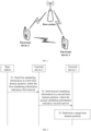
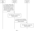
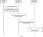
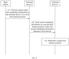
- the embodiments of this application provide a time domain resource indication method based on a communications system shown in FIG. 1 .
- the communications system includes at least a network device and two electronic devices.
- the two electronic devices in the communications system may be terminal devices that directly communicate with each other, and at least one of the two electronic devices may communicate with the network device, so that all other electronic devices in the communications system can communicate with the network device by using the electronic device.
- the electronic device that can communicate with the network device may be a relay node (Relay Node, RN), a base station, a terminal device, or the like, and an electronic device connected to the electronic device may be a terminal device or the like.
- Relay Node Relay Node
- the two electronic devices that may directly communicate with each other may be two terminal devices used for D2D communication, and the terminal devices used for D2D communication may also perform cellular communication with the network device.
- the two terminal devices that may directly communicate with each other may alternatively not be terminal devices using a D2D communications technology.
- the two terminal devices may be terminal devices using a Bluetooth or Wi-Fi technology, or may be terminal devices using another technology that belongs to future communications technologies and that may allow the terminal devices to directly communicate with each other. This is not limited in the embodiments of this application.
- the two electronic devices that may directly communicate with each other may alternatively be an RN and a terminal device, and the terminal device communicates with the network device by using the RN.
- Types of the two electronic devices in the communications system shown in FIG. 1 are not limited in the embodiments of this application. The following description is provided by using an example in which the two electronic devices in the communications system are terminal devices used for D2D communication.
- the two electronic devices may be a terminal device 1 and a terminal device 2, and the terminal device 1 is connected to the network device by using the terminal device 2, or the terminal device 1 communicates with the network device by using the terminal device 2.
- the communications system may be any radio access technology (Radio Access Technology, RAT) system, such as a new radio (New Radio, NR) system, wireless fidelity (Wi-Fi), worldwide interoperability for microwave access (Worldwide Interoperability for Microwave Access, WiMAX), a global system for mobile communications (Global System of Mobile communication, GSM), a code division multiple access (Code Division Multiple Access, CDMA) system, a wideband code division multiple access (Wideband Code Division Multiple Access, WCDMA) system, a general packet radio service (General Packet Radio Service, GPRS), a long term evolution (Long Term Evolution, LTE) system, an advanced long term evolution (Advanced long term evolution, LTE-A) system, a universal mobile telecommunications system (Universal Mobile Telecommunication System, UMTS), and a cellular system related to the 3rd generation partnership project (The 3rd Generation Partnership Project, 3GPP), a 4th generation mobile communications technology (4th Generation, 4G) network, or
- RAT radio access technology
- the method may further be applicable to a future-oriented communications technology.
- the system described in the embodiments of this application is intended to describe the technical solutions in the embodiments of this application more clearly, and constitute no limitation on the technical solutions provided in the embodiments of this application. A person of ordinary skill in the art may learn that, with evolution of network architectures, the technical solutions provided in the embodiments of this application are also applicable to a similar technical problem.
- the network device in the embodiments of this application may be a base station (Base Station, BS), a relay node (Relay Nodes, RN) device, or a device that is in an access network and that communicates with a wireless terminal device over an air interface by using one or more cells.
- the network device may be configured to perform mutual conversion between a received over-the-air frame and an IP packet and serve as a router between a terminal device and a rest part of the access network.
- the rest part of the access network may include an IP network.
- the network device may further coordinate attribute management of the air interface.
- the base station may include an evolved NodeB (NodeB, Evolved Node B, or evolutional Node B) in a long term evolution (Long Term Evolution, LTE) system or an evolved LTE system (LTE-Advanced, LTE-A), or may include a next generation NodeB (next generation node B, gNB) in a 5G system. This is not limited in the embodiments of this application.
- the terminal device in the embodiments of this application may include a device that provides a user with voice and/or data connectivity, for example, a handheld device with a wireless connection function, or a processing device connected to a wireless modem.
- the UE may communicate with a core network by using a radio access network (Radio Access Network, RAN), and exchange voice and/or data with the RAN.
- Radio Access Network Radio Access Network
- the terminal device may include user equipment (User Equipment, UE), a wireless terminal device, a mobile terminal device, a subscriber unit (Subscriber Unit), a subscriber station (Subscriber Station), a mobile station (Mobile Station), a mobile station (Mobile), a remote station (Remote Station), an access point (Access Point, AP), a remote terminal device (Remote Terminal), an access terminal device (Access Terminal), a user terminal device (User Terminal), a user agent (User Agent), a user device (User Device), and the like.
- User Equipment User Equipment
- the terminal device may include a mobile phone (referred to as a "cellular" phone), a computer with a mobile terminal device, a portable, pocket-sized, handheld, computer-embedded, or in-vehicle mobile apparatus, a smart wearable device, and the like.
- the terminal device may include a personal communication service (Personal Communication Service, PCS) phone, a cordless telephone set, a session initiation protocol (SIP) phone set, a wireless local loop (Wireless Local Loop, WLL) station, a personal digital assistant (Personal Digital Assistant, PDA), a smartwatch, a smart helmet, smart glasses, a smart band, and other devices.
- PCS Personal Communication Service
- SIP session initiation protocol
- WLL wireless local loop
- PDA Personal Digital Assistant
- the terminal device further includes a restricted device, for example, a device with relatively low power consumption, a device with a limited storage capability, or a device with a limited computing capability.
- a restricted device for example, a device with relatively low power consumption, a device with a limited storage capability, or a device with a limited computing capability.
- the terminal device includes information sensing devices such as a barcode, radio frequency identification (RFID), a sensor, a global positioning system (GPS), and a laser scanner.
- RFID radio frequency identification
- GPS global positioning system
- a quantity and a type of network devices and terminal devices in the communications system shown in FIG. 1 are merely examples and are not limited in the embodiments of this application.
- more network devices, more terminal devices that perform cellular communication with the network device, or more terminal devices that may directly communicate with each other, for example, more terminal devices that perform D2D communication may further be included.
- the communications system shown in FIG. 1 although the network device and the terminal devices are shown, the communications system may include but is not limited to the network device and the terminal devices.
- the communications system may further include a core network device or a device configured to carry a virtualized network function. This is obvious to a person of ordinary skill in the art, and details are not described herein.
- system and “network” in the embodiments of this application may be used interchangeably.
- “Plurality” means two or more.
- plural may also be understood as “at least two” in the embodiments of the present invention.
- “And/or” describes an association relationship between associated objects and represents that three relationships may exist.
- a and/or B may represent the following three cases: Only A exists, both A and B exist, and only B exists.
- the character “/”, unless otherwise specified, generally indicates an "or" relationship between the associated objects.
- the network device may send downlink control information (Downlink Control Information, DCI) to the terminal device 1 through a physical downlink control channel (Physical Downlink Control Channel, PDCCH), to indicate a resource position in which the terminal device 1 directly communicates with the terminal device 2; and then, the terminal device 1 sends or receives data in the resource position indicated by the network device.
- DCI Downlink Control Information
- PDCCH Physical Downlink Control Channel
- a first communications link is a link used when the terminal device 1 is directly connected to the network device, and is marked as L1; and a second communications link is a link used when the terminal device 1 is connected to the network device by using the terminal device 2, and is marked as L2.
- the terminal device 1 is referred to as remote UE, and the terminal device 2 is referred to as relay UE.
- the remote UE is connected to the network device by using the relay UE, the remote UE communicates with the network device by using the relay UE, data between the remote UE and the network device may be forwarded by using the relay UE, the remote UE is linked to the relay UE (remote UE is linked to remote UE, remote UE and relay UE are associated), or the remote UE and the relay UE are associated (remote UE and relay UE are associated).
- the network device when the network device allocates a resource to the remote UE, for example, the network device allocates a sidelink (Sidelink, SL) resource between the remote UE and the relay UE to the remote UE, or the network device allocates an uplink (Uplink, UL) resource to the remote UE, the network device can indicate the resource to the remote UE by using the relay UE; and after receiving indication information, the remote UE separately confirms a time domain resource position and a frequency domain resource position based on the indication information, to complete a resource allocation process.
- Sidelink Sidelink
- Uplink Uplink
- the embodiments of this application provide a resource indication method.
- Resource positions usually include a time domain resource position and a frequency domain resource position.
- the embodiments of this application include only a case in which a network device indicates an allocated time domain resource to remote UE by using relay UE.
- a first device determines, based on first scheduling information that is sent by a network device and that is received in a first time domain position, a second time domain position in which second scheduling information is sent to a second device or content of second scheduling information, so that after receiving the second scheduling information, the second device determines, based on the second scheduling information, a time domain position of a resource allocated by the network device to the second device.
- This can implement a process of forwarding, by the first device, signaling for scheduling the second device by the network device.
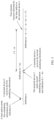
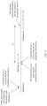
- FIG. 2 shows a time domain resource indication method. A process of the method is described as follows.
- Step 21 A base station sends first scheduling information to a terminal device 2 in a first time domain position, where the first scheduling information includes first indication information, and the first indication information is used to indicate a first interval.
- the base station may feed back scheduling information to a terminal device 1 in the first time domain position after receiving, before the first time domain position, a resource request sent by the terminal device 1 or a resource request forwarded by the terminal device 2; or the base station proactively initiates, in the first time domain position, a service of allocating a time domain resource to the terminal device 1, and then allocates the resource to the terminal device 1 based on resource usage.
- the first time domain position may be a specific time point, for example, the 10 th second, or may be represented in a form of a time scheduling unit, for example, a time domain position of the n th time scheduling unit.
- the time scheduling unit may be any one of a frame, a subframe, a slot, a mini-slot (mini-slot), and an orthogonal frequency division multiplexing (Orthogonal Frequency Division Multiplexing, OFDM) symbol.
- each time domain position is represented in a form of a subframe.
- the first time domain position is a subframe n.
- the base station receives, in the subframe n, the resource request sent by the terminal device 1, and in this case, determines, based on resource usage of a transmit link of the terminal device 1, a time domain position of the resource allocated to the terminal device 1.
- the base station determines that all time domain resources corresponding to a subframe (n + 1) to a subframe (n + T1 - 1) have been occupied, and there is an idle resource in a subframe (n + T1).
- the base station may allocate a time domain resource occupied by the subframe (n + T1) to the terminal device 1; may allocate time domain resources corresponding to the subframe (n + T1) to a subframe (n + T1 + 2) to the terminal device 1; or may allocate time domain resources corresponding to the subframe (n + T1), a subframe (n + T1 + 2), and a subframe (n + T1 + 4) to the terminal device 1.
- a time domain resource allocated by the base station to the terminal device 1 may be one subframe, a plurality of consecutive subframes, or a plurality of inconsecutive subframes. This is not limited herein.
- the base station may determine the first interval based on the time domain position of the resource allocated to the terminal device 1 and the first time domain position.
- the first interval may be an interval between a target time domain position and the first time domain position, the target time domain position is used by the terminal device 1 or the terminal device 2 to determine the time domain position of the resource, and the target time domain position may be the same as or not exactly the same as the time domain position of the resource.
- a meaning of the first interval may specifically include the following cases:
- the resource may be a plurality of consecutive subframes
- the target time domain position may be a starting position of the time domain position of the resource.
- the first interval may be an interval between the starting time domain position of the resource and the first time domain position.
- the first time domain position is the subframe n
- the base station determines that time domain resources allocated to the terminal device 1 are the subframe (n + T1) to the subframe (n + T1 + 2).
- an interval indicated by the first interval may be T1 subframes.
- the target time domain position may be the time domain position of the resource, or may be a position having a specific distance from the resource.
- the resource is a subframe
- the target time domain position may be a corresponding position having a distance of N subframes before the subframe.
- the first interval may be a difference between the N subframes and an interval between the first time domain position and the time domain position of the resource.
- the N subframes may be indicated in the first indication information, or pre-agreed on with the terminal device 1 and the terminal device 2.
- the target time domain position may be a specific position of the resource, for example, the target time domain position may be a midpoint position of the resource.
- the first interval is an interval between the midpoint position and the first time domain position.
- the first time domain position is the subframe n
- the base station determines that time domain resources allocated to the terminal device 1 are the subframe (n + T1) to the subframe (n + T1 + 2)
- the first interval may be (T1 + 1) subframes.
- an interval between the specific position of the resource and a starting position of the resource and an interval between the specific position of the resource and an ending position of the resource may be pre-agreed on between the base station, the terminal device 1, and, the terminal device 2.
- the specific position is the midpoint position of the resource, and both the interval between the specific position and the starting position and the interval between the specific position and the ending position of the resource are one subframe.
- the terminal device 1 considers by default that time domain resources occupied by a subframe that is immediately before the specific position to a subframe that is immediately after the specific position are time domain positions corresponding to the resource allocated by the base station to the terminal device 1.
- the target time domain position may be a starting position of a bitmap (bitmap) used for determining the time domain position of the resource allocated to the terminal device 1, so that the terminal device 1 or the terminal device 2 determines the time domain position of the resource based on the target position and the bitmap.
- bitmap a bitmap
- the bitmap may be 10010, and the target time domain position is a subframe (n + i), it indicates that subframes in which the resource allocated by the base station to the terminal device 1 is located are the subframe (n + i) and a subframe (n + i + 3).
- the bitmap may be indicated in the first scheduling information, or may be pre-agreed on by the base station with the terminal device 1 and the terminal device 2.
- the meaning of the first interval may be pre-agreed on between the base station, the terminal device 1, and the terminal device 2, or the meaning of the first interval may be added to the first scheduling information.
- a specific bit is added to the first scheduling information, where values of the bit may be 0 to 5, and respectively correspond to the foregoing four cases.
- the terminal device 1 determines the meaning of the first interval based on the values of the specific bit.
- a person skilled in the art may alternatively define the first interval in another manner. This is not limited in this embodiment of this application.
- the first time domain position is the subframe n
- the time domain position of the resource allocated by the base station to the terminal device 1 is the subframe (n + T1)
- the first interval indicates the interval between the first time domain position and the time domain position of the resource is used as an example for description.
- the base station sends the first scheduling information to the terminal device 2 in the subframe n, and indicates the first interval by using the first scheduling information.
- a value indicated by the first indication information is L1
- the first interval T1 indicated by using a value of L1 is a minimum value that meets both a condition that T1 is greater than or equal to (L1 + k) subframes and another condition, where k is an integer greater than or equal to 0, and k is specified in a standard protocol used by the base station or a terminal, or k is configured by the base station based on resource usage in a current network or another factor, or k is preset by the network device before the network device communicates with the terminal device 1 or the terminal device 2.
- a subframe corresponding to the time domain position of the allocated resource is the 1 st subframe whose starting time is not earlier than ⁇ starting time of the subframe n + T1 x time-domain length of a subframe - offset ⁇ .
- the offset may be TA/2
- TA is a timing advance of the terminal device 1
- TA N TA x Ts
- N TA is configured by the base station.
- the offset may be TA/2 + N TA offset ⁇ Ts, where a value of N TA offset is specified in a standard.
- the base station uses the first indication manner is used as an example for description.
- the base station After determining that the resource allocated to the terminal device 1 is the subframe (n + T1) and determining that the first indication information indicates L1, the base station sends, to the terminal device 1, the first scheduling information including the first indication information.
- the first scheduling information may be downlink control information (Downlink control information, DCI) sent through a physical downlink control channel (Physical downlink control channel, PDCCH), or certainly, may be information sent through another physical downlink channel. This is not limited in this embodiment of this application.
- Step 22 The terminal device 2 sends second scheduling information to the terminal device 1 in a second time domain position, where the second scheduling information includes second indication information.
- the terminal device 2 After the base station sends the first scheduling information to the terminal device 2 in the first time domain position, the terminal device 2 receives the first scheduling information in the first time domain position.
- the terminal device 2 when communicating with the base station, the terminal device 2 needs to obtain timing synchronization with the base station. Therefore, after the terminal device 2 obtains timing synchronization with the base station, the base station sends the first scheduling information in the first time domain position, to be specific, the subframe n. In this way, the terminal device 2 can determine that the terminal device 2 receives the first scheduling information in the first time domain position, to be specific, the subframe n.
- the terminal device 2 may send the second scheduling information in the second time domain position in either of the following two manners.
- the terminal device 2 determines the second time domain position based on the first time domain position and a known third interval.
- the third interval is specified in the standard protocol used by the terminal device, or is configured by the base station, or is preconfigured. Referring to FIG. 3 , the terminal device 2 receives the first scheduling information in the subframe n, and the third interval is m subframes. In this case, the terminal device 2 determines that the second time domain position is a subframe (n + m). The terminal device 2 further needs to determine second indication information included in the second scheduling information.
- the second indication information is used to indicate a second interval, and the second interval is a difference between the first interval and the third interval.
- the terminal device 2 receives the first scheduling information in the subframe n, and obtains that the value indicated by the first indication information in the first scheduling information is L1.
- the terminal device 2 determines, based on the preset value k, that the first interval indicated by the first indication information is the (L1 + k) subframes, to determine that the second interval is (L1 + k - m) subframes; and then indicates the second interval by using the second indication information.
- a subframe corresponding to the second time domain position is the 1 st subframe whose starting time is not earlier than ⁇ starting time of the subframe n + third interval x time-domain length of a subframe - offset ⁇ .
- the offset may be TA/2
- TA is a timing advance of the terminal device 1
- TA N TA ⁇ Ts
- N TA is configured by the base station.
- the offset may be TA/2 + N TA offset x Ts, where a value of N TA offset is specified in a standard.
- the terminal device selects a time domain position after the first time domain position, to send the second scheduling information.
- the selected time domain position is the second time domain position.
- the second time domain position is a subframe (n + m).
- the terminal device 2 determines, based on the second time domain position, the second indication information included in the second scheduling information.
- the second indication information is used to indicate a second interval.
- the second interval is a difference between the first interval and a third interval
- the third interval is a difference between the second time domain position and the first time domain position.
- the second interval is L1 + k - m.
- the terminal device 2 may indicate, in any one of the three indication manners of indicating, by the base station, the first interval by using the first indication information in step 21, the second interval by using the second indication information. Details are not described herein again. Specifically, the terminal device 2 may indicate, in the same manner as the manner of indicating, by the base station, the first interval by using the first indication information in step 21, the second interval by using the second indication information. For example, the first indication manner is used in both the cases. Certainly, the terminal device 2 may alternatively indicate, in a manner different from the manner of indicating, by the base station, the first interval by using the first indication information in step 21, the second interval by using the second indication information.
- the base station indicates, in the first indication manner, the first interval by using the first indication information
- the terminal device 2 indicates, in the second indication manner, the second interval by using the second indication information.
- the terminal device 2 may alternatively select any one of the manners depending on an actual case, to indicate the second interval. Certainly, if selecting an indication manner depending on the actual case, the terminal device 2 needs to notify the terminal device 1 of the indication manner. A specific notification manner is not limited herein.
- the terminal device 2 indicates, in the first indication manner in step 21, the second interval by using the second indication information is used as an example for description. If the terminal device 2 sends the second scheduling information in the first sending manner, the terminal device 2 determines that a value indicated by the second indication information is (L1 - m).
- the terminal device 2 After determining the second time domain position and the second scheduling information, the terminal device 2 sends the second scheduling information to the terminal device 1 in the second time domain position.
- the second scheduling information may be sidelink control information (Sidelink control information, SCI) sent through a physical sidelink control channel (Physical Sidelink Control Channel, PSCCH), or certainly, may be information sent through another physical channel. This is not limited in this embodiment of this application.
- Step 23 The terminal device 1 receives the second scheduling information and determines the target time domain position.
- the terminal device 1 After the terminal device 2 sends the second scheduling information to the terminal device 1 in the second time domain position, the terminal device 1 receives the second scheduling information in the second time domain position.
- the terminal device 1 when communicating with the terminal device 2, the terminal device 1 needs to obtain timing synchronization with the terminal device 2. Therefore, after the terminal device 1 obtains timing synchronization with the terminal device 2, the terminal device 2 sends the second scheduling information in the second time domain position, to be specific, the subframe (n + m). In this way, the terminal device 1 can determine that the terminal device 1 receives the second scheduling information in the second time domain position, to be specific, the subframe (n + m).
- the terminal device 1 After receiving the second scheduling information in the second time domain position, the terminal device 1 determines that the target time domain position is a time domain position corresponding to a sum of the second time domain position and the second interval indicated in the second scheduling information, to determine, based on the target time domain position, a time domain resource used by the terminal device 1 to send and/or receive data. It should be noted that, the terminal device 2 may indicate, in any one of the three indication manners of indicating, by the base station, the first interval by using the first indication information in step 21, the second interval by using the second indication information. Details are not described herein again. A manner of determining, by the terminal device 1 based on the target time domain position, the time domain resource used to send and/or receive the data may be determined in the four cases in step 21 of the target time domain position and the time domain position of the resource.
- the terminal device 1 receives the second scheduling information in the subframe (n + m), and obtains that the value indicated in the second scheduling information is (L1 - m), to indicate the second interval.
- the terminal device 1 can learn in advance the indication manner of indicating, by the terminal device 2, the second interval by using the second indication information. In other words, when the terminal device 2 indicates, in the first indication manner in step 21, the second interval by using the second indication information, the terminal device 1 can learn that the second interval is a sum of the value indicated in the second indication information and k in step 21.
- the second scheduling information carries the manner of indicating the second interval by the second indication information, or the manner of indicating the second interval by the second indication information is pre-agreed on between the terminal device 1 and the terminal device 2.
- a subframe corresponding to the target time domain position is the 1 st subframe whose starting time is not earlier than ⁇ starting time of the subframe (n + m) + second interval x time-domain length of a subframe - offset ⁇ .
- the offset may be TA/2
- TA is a timing advance of the terminal device 1
- TA N TA ⁇ Ts
- N TA is configured by the base station.
- the offset may be TA/2 + N TA offset ⁇ Ts, where a value of N TA offset is specified in a standard.
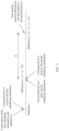
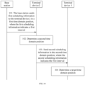
- FIG. 4 shows a resource indication method.
- a process of the method is as follows.
- Step 41 A base station sends first scheduling information to a terminal device 2 in a first time domain position, where the first scheduling information includes first indication information, and the first indication information is used to indicate a first interval.
- step 41 A specific implementation process of step 41 is the same as that of step 21, and details are not described herein again.
- the base station determines that a resource allocated to a terminal device 1 is a subframe (n + T1), and the base station indicates the first interval to the terminal device 2 in the first indication manner in step 21 and a value indicated by the first indication information is L1 is used as an example for description, as shown in FIG. 5 .
- Step 42 The terminal device 2 receives the first scheduling information and determines a second time domain position.
- the terminal device 2 After the base station sends the first scheduling information to the terminal device 2 in the first time domain position, the terminal device 2 receives the first scheduling information in the first time domain position.
- the terminal device 2 When communicating with the base station, the terminal device 2 needs to obtain timing synchronization with the base station. Therefore, after the terminal device 2 obtains timing synchronization with the base station, the base station sends the first scheduling information in the first time domain position, to be specific, the subframe n. In this way, the terminal device 2 can determine that the terminal device 2 receives the first scheduling information in the first time domain position, to be specific, the subframe n.
- the terminal device 2 After receiving the first scheduling information in the first time domain position, the terminal device 2 determines the second time domain value based on the first time domain position.
- the second time domain position is a sum of the first time domain position and a third interval
- the third interval is a difference between the first interval and a second interval.
- the second interval is predefined, or is configured by the network device, or is preconfigured, and the second interval is learned in advance by both the terminal device 1 and the terminal device 2.
- the terminal device 2 receives the first scheduling information in the subframe n, and obtains that the value indicated in the first indication information is L1.
- the terminal device 2 can learn in advance an indication manner of indicating, by the base station, the first interval by using the first indication information.
- the terminal device 1 can learn that the first interval is a sum of the value indicated in the first indication information and a preset value k.
- the first scheduling information carries the manner of indicating the first interval by the first indication information, or the manner of indicating the first interval by the first indication information is pre-agreed on between the base station and the terminal device 2.
- the terminal device 2 determines that the first interval is (L1 + k) subframes.
- the terminal device determines, based on the preset second interval, namely, T2 subframes, that the third interval is (L1 + k - T2) subframes, and finally determines, based on a sum of the subframe n and the third interval, namely, (L 1 + k - T2) subframes, that the second time domain position is a subframe (n + L1 + k - T2).
- a subframe corresponding to the second time domain position is the 1 st subframe whose starting time is not earlier than ⁇ starting time of the subframe n + third interval x time-domain length of a subframe - offset ⁇ .
- the offset may be TA/2
- TA is a timing advance of the terminal device 2
- TA N TA ⁇ Ts
- N TA is configured by the base station.
- the offset may be TA/2 + N TA offset ⁇ Ts, where a value of N TA offset is specified in a standard.
- Step 43 The terminal device 2 sends second scheduling information to the terminal device 1 in the second time domain position.
- the second scheduling information is used by the terminal device 1 to determine that a target time domain position is a sum of the second time domain position and the second interval, so as to determine, based on the target time domain position, a position of a time domain resource used to send and/or receive data.
- the second scheduling information does not include indication information used to indicate the time domain resource.
- the first scheduling information includes frequency domain position or other configuration information indicated to the terminal device 1
- the second scheduling information may also include the frequency domain position or the other configuration information indicated in the first scheduling information.
- a type of the second scheduling information is the same as that in step 22, for example, may be the SCI, and details are not described herein again.
- Step 44 The terminal device 1 receives the second scheduling information and determines the target time domain position.
- the terminal device 1 After the terminal device 2 sends the second scheduling information to the terminal device 1 in the second time domain position, the terminal device 1 receives the second scheduling information in the second time domain position.
- the terminal device 1 When communicating with the terminal device 2, the terminal device 1 needs to obtain timing synchronization with the terminal device 2. Therefore, after the terminal device 1 obtains timing synchronization with the terminal device 2, the terminal device 2 sends the second scheduling information in the second time domain position, to be specific, the subframe (n + L1 + k - T2). In this way, the terminal device 1 can determine that the terminal device 1 receives the second scheduling information in the second time domain position, to be specific, the subframe (n + L1 + k - T2).
- a manner of determining, by the terminal device 1 based on the target time domain position, the time domain resource used to send and/or receive the data may be determined in the four cases in step 21 of the target time domain position and the time domain position of the resource. Details are not described herein again.
- a subframe corresponding to the target time domain position is the 1 st subframe whose starting time is not earlier than ⁇ starting time of the subframe (n + m) + second interval x time-domain length of a subframe - offset ⁇ .
- the offset may be TA/2
- TA is a timing advance of the terminal device 1
- TA N TA ⁇ Ts
- N TA is configured by the base station.
- the offset may be TA/2 + N TA offset ⁇ Ts, where a value of N TA offset is specified in a standard.
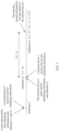
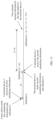
- FIG. 6 shows a resource indication method.
- a process of the method is as follows.
- Step 61 A base station sends first scheduling information to a terminal device 2 in a first time domain position, where the first scheduling information includes first indication information and second indication information, the first indication information is used to indicate a first interval, and the second indication information is used to indicate a second interval.
- the base station before sending the first scheduling information to the terminal device 2, the base station needs to determine a time domain position of a resource allocated to a terminal device 1.
- the process is the same as a corresponding process in step 21, and details are not described herein again.
- that the first time domain position is a subframe n
- the time domain position of the resource allocated by the base station to the terminal device 1 is a subframe (n + T1) is used as an example for description.
- the base station further needs to determine a time domain position in which the terminal 2 sends second scheduling information, determines the first indication information based on the first time domain position and the time domain position in which the terminal 2 sends the second scheduling information, and determines the second indication information based on the time domain position in which the terminal 2 sends the second scheduling information and the time domain position of the resource allocated to the terminal device 1.
- the first interval included in the first indication information is used to indicate a difference between the time domain position in which the terminal device 2 sends the second scheduling information and the first time domain position
- the second interval included in the second indication information is used to indicate a difference between a target time domain position and the time domain position in which the terminal device 2 sends the second scheduling information.
- a sum of the first interval and the second interval is a difference between the target time domain position and the first time domain position. To be specific, the sum of the first interval and the second interval is T1.
- Meanings of the first interval and the second interval, an indication manner of indicating the first interval by the first indication information, and an indication manner of indicating the second interval by the second indication information are similar to those in step 21. Details are not described herein again.
- the first indication manner is used to indicate both the first interval by the first indication information and the second interval by the second indication information is used as an example.
- a value indicated by the first indication information is L1
- the first interval is (L1 + k1) subframes
- a value indicated by the second indication information is L2
- the second interval is (L2 + k2) subframes.
- L1 + k1 + L2 + k2 T1
- k1 and k2 are respectively integers greater than or equal to 0, and are specified in a standard protocol used by the base station, or are configured by the base station based on resource usage in a current network or another factor, or are preset by the network device before the network device communicates with the terminal device 1 or the terminal device 2.
- a type of the first scheduling information is the same as that in step 21, for example, may be the DCI, and details are not described herein again.
- Step 62 The terminal device 2 receives the first scheduling information and determines a second time domain position.
- the terminal device 2 After the base station sends the first scheduling information to the terminal device 2 in the first time domain position, the terminal device 2 receives the first scheduling information in the first time domain position.
- the terminal device 2 when communicating with the base station, the terminal device 2 needs to obtain timing synchronization with the base station. Therefore, after the terminal device 2 obtains timing synchronization with the base station, the base station sends the first scheduling information in the first time domain position, to be specific, the subframe n. In this way, the terminal device 2 can determine that the terminal device 2 receives the first scheduling information in the first time domain position, to be specific, the subframe n.
- the terminal device 2 After receiving the first scheduling information in the first time domain position, the terminal device 2 determines that the second time domain position is a sum of the first time domain position and the first interval.
- the terminal device 2 can learn in advance an indication manner of indicating, by the base station, the first interval by using the first indication information.
- the terminal device 1 can learn that the first interval is a sum of the value indicated in the first indication information and a preset value k.
- the first scheduling information carries the manner of indicating the first interval by the first indication information, or the manner of indicating the first interval by the first indication information is pre-agreed on between the base station and the terminal device 2.
- the terminal device 2 determines that the second time domain position is a subframe (n + L1 + k), as shown in FIG. 7 .
- Step 63 The terminal device 2 sends the second scheduling information to the terminal device 1 in the second time domain position, where the second scheduling information includes third indication information, and the third indication information is used to indicate the second interval.
- the second scheduling information is used by the terminal device 1 to determine that the target time domain position is a sum of the second time domain position and the second interval, so as to determine, based on the target time domain position, a position of a time domain resource used to send and/or receive data.
- the terminal device 2 may indicate, in any one of the three indication manners in step 21, the second interval by using the third indication information. Details are not described herein again. In this embodiment of this application, that the terminal device 2 uses the first indication manner is used as an example for description. To be specific, a value indicated by the third indication information is L2, indicating that the second interval is (L2 + k) subframes.
- the second scheduling information may also include the frequency domain position or the other configuration information indicated in the first scheduling information.
- a type of the second scheduling information is the same as that in step 22, for example, may be the SCI, and details are not described herein again.
- a subframe corresponding to the second time domain position is the 1 st subframe whose starting time is not earlier than ⁇ starting time of the subframe n + first interval ⁇ time-domain length of a subframe - offset ⁇ .
- the offset may be TA/2
- TA is a timing advance of the terminal device 1
- TA N TA x Ts
- N TA is configured by the base station.
- the offset may be TA/2 + N TA offset ⁇ Ts, where a value of N TA offset is specified in a standard.
- Step 64 The terminal device 1 receives the second scheduling information and determines the target time domain position.
- the terminal device 1 After the terminal device 2 sends the second scheduling information to the terminal device 1 in the second time domain position, the terminal device 1 receives the second scheduling information in the second time domain position.
- the terminal device 1 When communicating with the terminal device 2, the terminal device 1 needs to obtain timing synchronization with the terminal device 2. Therefore, after the terminal device 1 obtains timing synchronization with the terminal device 2, the terminal device 2 sends the second scheduling information in the second time domain position, to be specific, the subframe (n + L1 + k). In this way, the terminal device 1 can determine that the terminal device 1 receives the second scheduling information in the second time domain position, to be specific, the subframe (n + L1 + k).
- the terminal device 1 After receiving the second scheduling information in the second time domain position, the terminal device 1 determines that the target time domain position is the sum of the second time domain position and the second interval. Certainly, the terminal device 1 can learn in advance the indication manner of indicating, by the terminal device 1, the second interval by using the second indication information. In other words, when the terminal device 2 indicates, in the first indication manner in step 21, the second interval by using the third indication information, the terminal device 1 can learn that the second interval is a sum of the value indicated in the second indication information and k.
- the first scheduling information carries the manner of indicating the first interval by the first indication information, or the manner of indicating the first interval by the first indication information is pre-agreed on between the base station and the terminal device 2. Certainly, there may be another manner.
- a manner of determining, by the terminal device 1 based on the target time domain position, the time domain resource used to send and/or receive the data may be determined in the four cases in step 21 of the target time domain position and the time domain position of the resource. Details are not described herein again.
- a subframe corresponding to the target time domain position is the 1 st subframe whose starting time is not earlier than ⁇ starting time of the subframe (n + m) + second interval x time-domain length of a subframe - offset ⁇ .
- offset may be TA/2
- TA is a timing advance of the terminal device 1
- TA N TA ⁇ Ts
- N TA is configured by the base station.
- the offset may be TA/2 + N TA offset ⁇ Ts, where a value of N TA offset is specified in a standard.
- FIG. 8 shows a resource indication method.
- a process of the method is as follows.
- Step 81 A base station sends first scheduling information to a terminal device 2 in a first time domain position, where the first scheduling information includes first indication information, and the first indication information is used to indicate a first interval.
- the base station before sending the first scheduling information to the terminal device 2, the base station needs to determine a time domain position of a resource allocated to a terminal device 1.
- the process is the same as a corresponding process in step 21, and details are not described herein again.
- that the first time domain position is a subframe n
- the time domain position of the resource allocated by the base station to the terminal device 1 is a subframe (n + T1) is used as an example for description.
- the base station further needs to determine the first indication information.
- the first interval included in the first indication information is used to indicate a difference between the first time domain position and a time domain position in which the terminal device 2 sends second scheduling information.
- a second interval T2 is preset on the base station, the terminal device 1, and the terminal device 2, and the second interval is predefined, or is configured by the network device, or is preconfigured.
- the base station can determine that the first interval is a difference between a third interval and the second interval, and the third interval is a difference between a target time domain position and the first time domain position.
- the first interval is (T1 - T2).
- a meaning of the first interval and an indication manner of indicating the first interval by the first indication information are similar to those in step 21. Details are not described herein again.
- that the first interval has the first meaning, and the first interval is indicated by the first indication information in the first indication manner is used as an example.
- a value indicated by the first indication information is L1
- the first interval is (L1 + k) subframes
- L1 + k T1 - T2
- k is an integer greater than or equal to 0
- k is specified in a standard protocol used by the base station, or k is configured by the base station based on resource usage in a current network or another factor, or k is preset by the network device before the network device communicates with the terminal device 1 or the terminal device 2.
- a type of the first scheduling information is the same as that in step 21, for example, may be the DCI, and details are not described herein again.
- Step 82 The terminal device 2 receives the first scheduling information and determines a second time domain position.
- the terminal device 2 After the base station sends the first scheduling information to the terminal device 2 in the first time domain position, the terminal device 2 receives the first scheduling information in the first time domain position.
- the terminal device 2 when communicating with the base station, the terminal device 2 needs to obtain timing synchronization with the base station. Therefore, after the terminal device 2 obtains timing synchronization with the base station, the base station sends the first scheduling information in the first time domain position, to be specific, the subframe n. In this way, the terminal device 2 can determine that the terminal device 2 receives the first scheduling information in the first time domain position, to be specific, the subframe n.
- the terminal device 2 After receiving the first scheduling information in the first time domain position, the terminal device 2 determines that the second time domain position is a sum of the first time domain position and the first interval.
- the terminal device 2 can learn in advance the indication manner of indicating, by the base station, the first interval by using the first indication information.
- the terminal device 1 can learn that the first interval is a sum of the value indicated in the first indication information and a preset value k.
- the first scheduling information carries the manner of indicating the first interval by the first indication information, or the manner of indicating the first interval by the first indication information is pre-agreed on between the base station and the terminal device 2.
- the terminal device 2 determines that the second time domain position is a subframe (n + L1 + k), as shown in FIG. 9 .
- Step 83 The terminal device 2 sends second scheduling information to the terminal device 1 in the second time domain position.
- the second scheduling information is used by the terminal device 1 to determine that the target time domain position is a sum of the second time domain position and the preset second interval, so as to determine, based on the target time domain position, a position of the time domain resource used to send and/or receive the data.
- the second scheduling information does not include indication information used to indicate the time domain resource.
- the first scheduling information includes frequency domain position or other configuration information indicated to the terminal device 1
- the second scheduling information may also include the frequency domain position or the other configuration information indicated in the first scheduling information.
- a type of the second scheduling information is the same as that in step 22, for example, may be the SCI, and details are not described herein again.
- a subframe corresponding to the second time domain position is the 1 st subframe whose starting time is not earlier than ⁇ starting time of the subframe n + first interval x time-domain length of a subframe - offset ⁇ .
- the offset may be TA/2
- TA is a timing advance of the terminal device 1
- TA N TA x Ts
- N TA is configured by the base station.
- the offset may be TA/2 + N TA offset ⁇ Ts, where a value of N TA offset is specified in a standard.
- Step 84 The terminal device 1 receives the second scheduling information and determines the target time domain position.
- the terminal device 1 After the terminal device 2 sends the second scheduling information to the terminal device 1 in the second time domain position, the terminal device 1 receives the second scheduling information in the second time domain position.
- the terminal device 1 when communicating with the terminal device 2, the terminal device 1 needs to obtain timing synchronization with the terminal device 2. Therefore, after the terminal device 1 obtains timing synchronization with the terminal device 2, the terminal device 2 sends the second scheduling information in the second time domain position, to be specific, the subframe (n + L1 + k). In this way, the terminal device 1 can determine that the terminal device 1 receives the second scheduling information in the second time domain position, to be specific, the subframe (n + L1 + k).
- a manner of determining, by the terminal device 1 based on the target time domain position, the time domain resource used to send and/or receive the data may be determined in the four cases in step 21 of the target time domain position and the time domain position of the resource. Details are not described herein again.
- a subframe corresponding to the target time domain position is the 1 st subframe whose starting time is not earlier than ⁇ starting time of the subframe (n + m) + second interval ⁇ time-domain length of a subframe - offset ⁇ .
- the offset may be TA/2
- TA is a timing advance of the terminal device 1
- TA N TA ⁇ Ts
- N TA is configured by the base station.
- the offset may be TA/2 + N TA offset x Ts, where a value of N TA offset is specified in a standard.
- FIG. 10 shows a resource indication method.
- a process of the method is as follows.
- Step 101 A base station sends first scheduling information to a terminal device 2 in a first time domain position, where the first scheduling information includes first indication information, and the first indication information is used to indicate a first interval.
- the base station before sending the first scheduling information to the terminal device 2, the base station needs to determine a time domain position of a resource allocated to a terminal device 1.
- the process is the same as a corresponding process in step 21, and details are not described herein again.
- that the first time domain position is a subframe n
- the time domain position of the resource allocated by the base station to the terminal device 1 is a subframe (n + T1) is used as an example for description.
- the base station further needs to determine the first indication information.
- the first interval included in the first indication information is used to indicate a difference between a target time domain position and a time domain position in which the terminal device 2 sends second scheduling information.
- a second interval m is preset on the base station and the terminal device 2, and the second interval is predefined, or is configured by the network device, or is preconfigured.
- the base station can determine that the first interval is a difference between a third interval and the second interval, and the third interval is a difference between the target time domain position and the first time domain position.
- the first interval is (T1- m).
- a meaning of the first interval and an indication manner of indicating the first interval by the first indication information are similar to those in step 21. Details are not described herein again.
- the first interval has the first meaning
- the indication manner of indicating the first interval by the first indication information is the first indication manner is used as an example.
- a value indicated by the first indication information is L1
- the first interval is (L1 + k) subframes
- L1 + k T1 - m
- k is an integer greater than or equal to 0
- k is specified in a standard protocol used by the base station, or k is configured by the base station based on resource usage in a current network or another factor, or k is preset by the network device before the network device communicates with the terminal device 1 or the terminal device 2.
- a type of the first scheduling information is the same as that in step 21, for example, may be the DCI, and details are not described herein again.
- Step 102 The terminal device 2 receives the first scheduling information and determines a second time domain position.
- the terminal device 2 After the base station sends the first scheduling information to the terminal device 2 in the first time domain position, the terminal device 2 receives the first scheduling information in the first time domain position.
- the terminal device 2 when communicating with the base station, the terminal device 2 needs to obtain timing synchronization with the base station. Therefore, after the terminal device 2 obtains timing synchronization with the base station, the base station sends the first scheduling information in the first time domain position, to be specific, the subframe n. In this way, the terminal device 2 can determine that the terminal device 2 receives the first scheduling information in the first time domain position, to be specific, the subframe n.
- the terminal device 2 After receiving the first scheduling information in the first time domain position, the terminal device 2 determines that the second time domain position is a sum of the first time domain position and the preset second interval. For example, the second interval is m subframes. As shown in FIG. 11 , the second time domain position is a subframe (n + m).
- Step 103 The terminal device 2 sends the second scheduling information to the terminal device 1 in the second time domain position, where the second scheduling information includes second indication information, and the second indication information is used to indicate the first interval.
- the second scheduling information is used by the terminal device 1 to determine that the target time domain position is a sum of the second time domain position and the first interval, so as to determine, based on the target time domain position, a position of a time domain resource used to send and/or receive data.
- the terminal device 2 may indicate, in any one of the three indication manners in step 21, the first interval by using the second indication information. Details are not described herein again. In this embodiment of this application, that the terminal device 2 uses the first indication manner is used as an example for description. To be specific, a value indicated by the second indication information is L1, indicating that the first interval is (L1 + k) subframes.
- the second scheduling information may also include the frequency domain position or the other configuration information indicated in the first scheduling information.
- a type of the second scheduling information is the same as that in step 22, for example, may be the SCI, and details are not described herein again.
- a subframe corresponding to the second time domain position is the 1 st subframe whose starting time is not earlier than ⁇ starting time of the subframe n + second interval ⁇ time-domain length of a subframe - offset ⁇ .
- the offset may be TA/2
- TA is a timing advance of the terminal device 1
- TA N TA ⁇ Ts
- N TA is configured by the base station.
- the offset may be TA/2 + N TA offset ⁇ Ts, where a value of N TA offset is specified in a standard.
- Step 104 The terminal device 1 receives the second scheduling information and determines the target time domain position.
- the terminal device 1 After the terminal device 2 sends the second scheduling information to the terminal device 1 in the second time domain position, the terminal device 1 receives the second scheduling information in the second time domain position.
- the terminal device 1 When communicating with the terminal device 2, the terminal device 1 needs to obtain timing synchronization with the terminal device 2. Therefore, after the terminal device 1 obtains timing synchronization with the terminal device 2, the terminal device 2 sends the second scheduling information in the second time domain position, to be specific, the subframe (n + m). In this way, the terminal device 1 can determine that the terminal device 1 receives the second scheduling information in the second time domain position, to be specific, the subframe (n + m).
- the terminal device 1 After receiving the second scheduling information in the second time domain position, the terminal device 1 determines that the target time domain position is the sum of the second time domain position and the first interval. Certainly, the terminal device 1 can learn in advance the indication manner of indicating, by the terminal device 1, the first interval by using the second indication information. To be specific, when the terminal device 2 indicates, in the first indication manner in step 21, the first interval by using the second indication information, the terminal device 1 can learn that the first interval is a sum of the value indicated in the second indication information and k.
- the first scheduling information carries the manner of indicating the first interval by the first indication information, or the manner of indicating the first interval by the first indication information is pre-agreed on between the base station and the terminal device 2. Certainly, there may be another manner.
- a manner of determining, by the terminal device 1 based on the target time domain position, the time domain resource used to send and/or receive the data may be determined in the four cases in step 21 of the target time domain position and the time domain position of the resource. Details are not described herein again.
- a subframe corresponding to the target time domain position is the 1 st subframe whose starting time is not earlier than ⁇ starting time of the subframe (n + m) + first interval x time-domain length of a subframe - offset ⁇ .
- the offset may be TA/2
- TA is a timing advance of the terminal device 1
- TA N TA ⁇ Ts
- N TA is configured by the base station.
- the offset may be TA/2 + N TA offset ⁇ Ts, where a value of N TA offset is specified in a standard.
- FIG. 12 shows a resource indication method.
- a process of the method is as follows.
- Step 121 A base station sends first scheduling information to a terminal device 2 in a first time domain position.
- the base station before sending the first scheduling information to the terminal device 2, the base station needs to determine a time domain position of a resource allocated to a terminal device 1.
- a first interval and a second interval are preset on the base station, the terminal device 1, and the terminal device 2, the first interval is a difference m between the first time domain position and a time domain position in which the terminal device 2 sends second scheduling information, and the second interval is a difference T2 between a target time domain position and the time domain position in which the terminal device 2 sends the second scheduling information.
- the base station may determine, based on resource usage, that a subframe (n + m + T2) may be allocated to the terminal device 1. Then, the base station determines that the first time domain position is a subframe n, and sends the first scheduling information to the terminal device 1 in the subframe n.
- first interval and the second interval may have either of the two meanings in step 21, and the first interval and the second interval may be indicated in any one of the three indication manners in step 21.
- first interval and the second interval have the first meaning, and the first interval and the second interval are indicated in the first indication manner is used as an example for description.
- a type of the first scheduling information is the same as that in step 21, for example, may be the DCI, and details are not described herein again.
- Step 122 The terminal device 2 receives the first scheduling information and determines a second time domain position.
- the terminal device 2 After the base station sends the first scheduling information to the terminal device 2 in the first time domain position, the terminal device 2 receives the first scheduling information in the first time domain position.
- the terminal device 2 when communicating with the base station, the terminal device 2 needs to obtain timing synchronization with the base station. Therefore, after the terminal device 2 obtains timing synchronization with the base station, the base station sends the first scheduling information in the first time domain position, to be specific, the subframe n. In this way, the terminal device 2 can determine that the terminal device 2 receives the first scheduling information in the first time domain position, to be specific, the subframe n.
- the terminal device 2 After receiving the first scheduling information in the first time domain position, the terminal device 2 determines that the second time domain position is a sum of the first time domain position and the preset first interval. As shown in FIG. 13 , the terminal device 2 receives the first scheduling information in the subframe n, and determines, based on the preset first interval m, that the second time domain position is a subframe (n + m).
- Step 123 The terminal device 2 sends second scheduling information to the terminal device 1 in the second time domain position.
- the second invoking information is used by the terminal device 1 to determine that the target time domain position is a sum of the second time domain position and the preset second interval.
- the second scheduling information does not include indication information used to indicate a time domain resource.
- the first scheduling information includes frequency domain position or other configuration information indicated to the terminal device 1
- the second scheduling information may also include the frequency domain position or the other configuration information indicated in the first scheduling information.
- a type of the second scheduling information is the same as that in step 22, for example, may be the SCI, and details are not described herein again.
- a subframe corresponding to the second time domain position is the 1 st subframe whose starting time is not earlier than ⁇ starting time of the subframe n + first interval ⁇ time-domain length of a subframe - offset ⁇ .
- the offset may be TA/2
- TA is a timing advance of the terminal device 1
- TA N TA ⁇ Ts
- N TA is configured by the base station.
- the offset may be TA/2 + N TA offset ⁇ Ts, where a value of N TA offset is specified in a standard.
- Step 124 The terminal device 1 receives the second scheduling information and determines the target time domain position.
- the terminal device 1 After the terminal device 2 sends the second scheduling information to the terminal device 1 in the second time domain position, the terminal device 1 receives the second scheduling information in the second time domain position.
- the terminal device 1 when communicating with the terminal device 2, the terminal device 1 needs to obtain timing synchronization with the terminal device 2. Therefore, after the terminal device 1 obtains timing synchronization with the terminal device 2, the terminal device 2 sends the second scheduling information in the second time domain position, to be specific, the subframe (n + m). In this way, the terminal device 1 can determine that the terminal device 1 receives the second scheduling information in the second time domain position, to be specific, the subframe (n + m).
- the terminal device 1 After receiving the second scheduling information in the second time domain position, the terminal device 1 determines that the target time domain position is the sum of the second time domain position and the preset second interval. Referring to FIG. 13 , after receiving the second scheduling information in the subframe (n + m), the terminal device 1 determines, based on a value T2 of the preset second interval, that the target time domain position is a subframe (n + m + T2), to determine, based on the target time domain position, a time domain resource used by the terminal device 1 to send and/or receive data, and complete a process of indicating, by the base station to the terminal device 2 by using the terminal device 1, a time domain resource allocated to the terminal device 1.
- a manner of determining, by the terminal device 1 based on the target time domain position, the time domain resource used to send and/or receive the data may be determined in the four cases in step 21 of the target time domain position and the time domain position of the resource. Details are not described herein again.
- a subframe corresponding to the target time domain position is the 1 st subframe whose starting time is not earlier than ⁇ starting time of the subframe (n + m) + second interval ⁇ time-domain length of a subframe - offset ⁇ .
- the offset may be TA/2
- TA is a timing advance of the terminal device 1
- TA N TA ⁇ Ts
- N TA is configured by the base station.
- the offset may be TA/2 + N TA offset ⁇ Ts, where a value of N TA offset is specified in a standard.
- FIG. 14 shows a resource indication method.
- a process of the method is as follows.
- Step 141 A base station sends first scheduling information to a terminal device 2 in a first time domain position.
- the base station before sending the first scheduling information to the terminal device 2, the base station needs to determine a time domain position of a resource allocated to a terminal device 1.
- a third interval is preset on the base station, the terminal device 1, and the terminal device 2, and the third interval is a difference T1 between a target time domain position and the first time domain position.
- the base station may determine, based on resource usage, that a subframe (n + T1) may be allocated to the terminal device 1. Then, the base station determines that the first time domain position is a subframe n, and sends the first scheduling information to the terminal device 1 in the subframe n.
- the base station may send the first scheduling information in either of the following two manners.
- the first scheduling information does not include indication information used to indicate a time domain resource.
- the first scheduling information is used by the terminal device 1 to determine that the target time domain position is a sum of the first time domain position and the preset third interval. It should be noted that, the first scheduling information further includes frequency domain position or other configuration information indicated to the terminal device 1. This is not limited herein.
- a type of the first scheduling information is the same as that in step 21, for example, may be the DCI, and details are not described herein again.
- the first scheduling information includes second indication information, and the second indication information is used to indicate a first interval.
- the first interval is a difference between the first time domain position and a time domain position in which the terminal device 2 sends second scheduling information.
- the first interval is m subframes.
- the first interval, a second interval, and the third interval may have any one of the four meanings in step 21, and the first interval, the second interval, and the third interval may be indicated in any one of the three indication manners in step 21.
- the first interval, the second interval, and the third interval have the first meaning, and the first interval, the second interval, and the third interval are indicated in the first indication manner is used as an example for description.
- a type of the first scheduling information is the same as that in step 21, for example, may be the DCI, and details are not described herein again.
- Step 142 The terminal device 2 sends the second scheduling information to the terminal device 1 in a second time domain position, where the second scheduling information includes first indication information, the first indication information is used to indicate the first interval, the second scheduling information is used by the terminal device 1 to determine that the target time domain position is a sum of the second time domain position and the second interval, and the second interval is a difference between the preset third interval and the first interval indicated in the first indication information.
- the second scheduling information includes first indication information
- the first indication information is used to indicate the first interval
- the second scheduling information is used by the terminal device 1 to determine that the target time domain position is a sum of the second time domain position and the second interval
- the second interval is a difference between the preset third interval and the first interval indicated in the first indication information.
- the terminal device 2 After the base station sends the first scheduling information to the terminal device 2 in the first time domain position, the terminal device 2 receives the first scheduling information in the first time domain position.
- the terminal device 2 When communicating with the base station, the terminal device 2 needs to obtain timing synchronization with the base station. Therefore, after the terminal device 2 obtains timing synchronization with the base station, the base station sends the first scheduling information in the first time domain position, to be specific, the subframe n. In this way, the terminal device 2 can determine that the terminal device 2 receives the first scheduling information in the first time domain position, to be specific, the subframe n.
- the terminal device 2 For a first sending manner, after receiving the first scheduling information, the terminal device 2 selects a time domain position after the first time domain position, to send the second scheduling information to the terminal device 1. For example, the terminal device 2 sends the second scheduling information to the terminal device 1 in a selected subframe (n + m), where m is a value greater than 0 and less than or equal to the third interval T1.
- the terminal device 2 determines, based on the first interval indicated in the first scheduling information, that the second time domain position is a sum of the first time domain position and the first interval, and then sends the second scheduling information to the terminal device 1 in the determined second time domain position. As shown in FIG. 15 , after receiving the first scheduling information in the subframe n, the terminal device 2 determines that the second time domain position is the subframe (n + m), and sends the second scheduling information to the terminal device 1 in the subframe (n + m).
- a type of the second scheduling information is the same as that in step 22, for example, may be the SCI, and details are not described herein again.
- a subframe corresponding to the second time domain position is the 1 st subframe whose starting time is not earlier than ⁇ starting time of the subframe n + first interval x time-domain length of a subframe - offset ⁇ .
- the offset may be TA/2
- TA is a timing advance of the terminal device 1
- TA N TA ⁇ Ts
- N TA is configured by the base station.
- the offset may be TA/2 + N TA offset ⁇ Ts, where a value of N TA offset is specified in a standard.
- Step 143 The terminal device 1 receives the second scheduling information, and determines the target time domain position.
- the terminal device 1 After the terminal device 2 sends the second scheduling information to the terminal device 1 in the second time domain position, the terminal device 1 receives the second scheduling information in the second time domain position.
- the terminal device 1 when communicating with the terminal device 2, the terminal device 1 needs to obtain timing synchronization with the terminal device 2. Therefore, after the terminal device 1 obtains timing synchronization with the terminal device 2, the terminal device 2 sends the second scheduling information in the second time domain position, to be specific, the subframe (n + m). In this way, the terminal device 1 can determine that the terminal device 1 receives the second scheduling information in the second time domain position, to be specific, the subframe (n + m).
- the terminal device 1 After receiving the second scheduling information in the second time domain position, the terminal device 1 determines that the target time domain resource position is the sum of the second time domain position and the second interval.
- the second interval is a difference between the preset third interval and the first interval indicated in the first indication information.
- a manner of determining, by the terminal device 1 based on the target time domain position, the time domain resource used to send and/or receive the data may be determined in the four cases in step 21 of the target time domain position and the time domain position of the resource. Details are not described herein again.
- a subframe corresponding to the target time domain position is the 1 st subframe whose starting time is not earlier than ⁇ starting time of the subframe (n + m) + second interval x time-domain length of a subframe - offset ⁇ .
- the offset may be TA/2
- TA is a timing advance of the terminal device 1
- TA N TA x Ts
- N TA is configured by the base station.
- the offset may be TA/2 + N TA offset ⁇ Ts, where a value of N TA offset is specified in a standard.
- content indicated in the first scheduling information and the second scheduling information, a time point for sending the scheduling information, and intervals preset on the network device, the first device, and the second device are properly designed, so that after receiving the scheduling information sent by the first device, the second device can determine, based on the scheduling information, the time domain resource allocated by the network device to the second device.
- This can implement a process of forwarding, by the first device, signaling for scheduling the second device by the network device.
- the network elements such the terminal device 1, the terminal device 2, and the base station include corresponding hardware structures and/or software modules for performing the functions.
- the network elements such the terminal device 1, the terminal device 2, and the base station include corresponding hardware structures and/or software modules for performing the functions.
- units and algorithm steps may be implemented by hardware or a combination of hardware and computer software in this application. Whether a function is performed by hardware or hardware driven by computer software depends on particular applications and design constraints of the technical solutions. A person skilled in the art may use different methods to implement the described functions for each particular application, but it should not be considered that the implementation goes beyond the scope of this application.
- FIG. 16 is a possible schematic structural diagram of a network device 1600.
- the network device 1600 may be the base station shown in FIG. 1 .
- the network device 1600 may implement a function of the base station described above.
- the network device 1600 may include a processing unit 1601 and a transceiver unit 1602.
- the processing unit 1601 and the transceiver unit 1602 may be configured to perform step 21 in the embodiment shown in FIG. 2 , step 41 in the embodiment shown in FIG. 4 , step 61 in FIG. 6 , step 81 in FIG. 8 , step 101 in FIG. 10 , step 121 in FIG. 12 , and step 141 in FIG. 14 , and/or configured to support another process in the technology described in this specification. All related content of the steps in the foregoing methods may be cited in function descriptions of corresponding function modules. Details are not described herein again.
- FIG. 17 is a possible schematic structural diagram of a communications apparatus 1700.
- the communications apparatus 1700 may be the terminal device 2 shown in FIG. 1 .
- the communications apparatus 1700 may implement a function of the terminal device 2 described above.
- the network device 1700 may include a processing unit 1701 and a transceiver unit 1702.
- the processing unit 1701 may be configured to perform step 22 in FIG. 2 , step 42 in FIG. 4 , step 62 in FIG. 6 , step 82 in FIG. 8 , step 102 in FIG. 10 , step 122 in FIG. 12 , and step 142 in FIG. 14 , and/or configured to support another process in the technology described in this specification.
- the transceiver unit 1702 may be configured to perform step 22 in FIG. 2 , step 43 in FIG.
- step 63 in the FIG. 6 step 83 in FIG. 8 , step 103 in FIG. 10 , step 123 in FIG. 12 , and step 142 in FIG. 14 , and/or configured to support another process in the technology described in this specification. All related content of the steps in the foregoing methods may be cited in function descriptions of corresponding function modules. Details are not described herein again.
- the network device 1600 and the communications apparatus 1700 are presented in a form in which each function module corresponding to each function is obtained by division, or may be presented in a form in which each function module is divided in an integrated manner.
- the "module” herein may be an application-specific integrated circuit (application-specific integrated circuit, ASIC), a processor and a memory for executing one or more software or firmware programs, an integrated logic circuit, and/or another component that can provide the foregoing functions.
- the network device 1600 and the communications apparatus 1700 may further be implemented by using a structure shown in FIG. 18 .
- a communications apparatus 1800 may include a memory 1801, a processor 1802, a system bus 1803, and a communications interface 1804.
- the processor 1802, the memory 1801, and the communications interface 1804 are connected by using the system bus 1803.
- the memory 1801 is configured to store a computer execution instruction.
- the processor 1802 executes the computer execution instruction stored in the memory 1801, so that the communications apparatus 1800 performs the resource indication methods provided in FIG. 2 , FIG. 4 , FIG. 6 , FIG. 8 , FIG. 10 , FIG. 12 , and FIG. 14 .
- the communications interface 1804 may be a transceiver, or an independent receiver and transmitter.
- the transceiver unit 1602 may correspond to the communications interface 1804 in FIG. 18 .
- the processing unit 1601 may be built in or independent of the memory 1801 in the communications apparatus 1800 in a hardware/software form.
- the transceiver unit 1702 may correspond to the communications interface 1804 in FIG. 18 .
- the processing unit 1701 may be built in or independent of the memory 1801 in the communications apparatus 1800 in a hardware/software form.
- the memory 1801 may include a volatile memory, for example, a RAM.
- the memory 1801 may also include a nonvolatile memory, such as a flash memory, an HDD, or an SSD.
- the memory 1801 may alternatively include a combination of the foregoing types of memories.
- the processor 1802 may be a CPU, an NP, or a combination of a CPU and an NP.
- the processor 1202 may further include a hardware chip.
- the hardware chip may be an ASIC, a PLD, or a combination thereof.
- the PLD may be a CPLD, an FPGA, a GAL, or any combination thereof.
- the system bus 1803 may be a PCI bus, an EIS bus, or the like.
- the bus may be classified into an address bus, a data bus, a control bus, and the like.
- only one bold line is used to represent the system bus in FIG. 18 , but this does not mean that there is only one bus or only one type of bus.
- the system bus 1803 may be replaced with another connection structure, for example, a star structure. This is not limited in this embodiment of this application.
- the apparatus 1800 may be a field-programmable gate array (field-programmable gate array, FPGA), an application-specific integrated circuit (application specific integrated circuit, ASIC), a system on chip (system on chip, SoC), a central processing unit (central processor unit, CPU), a network processor (network processor, NP), a digital signal processing circuit (digital signal processor, DSP), a micro controller unit (micro controller unit, MCU), a programmable logic device (programmable logic device, PLD), or another integrated chip.
- field-programmable gate array field-programmable gate array
- FPGA field-programmable gate array
- ASIC application specific integrated circuit
- SoC system on chip
- CPU central processing unit
- CPU central processor unit, CPU
- network processor network processor
- NP digital signal processing circuit
- DSP digital signal processor
- micro controller unit micro controller unit
- MCU programmable logic device
- PLD programmable logic device
- the communications apparatus and the network device provided in this application may be a chip system, and the chip system may include at least one chip, and may further include another discrete device.
- the chip system may be disposed in the communications apparatus or the network device, and supports the communications apparatus or the network device to complete the resource indication methods provided.
- An embodiment of this application provides a computer storage medium.
- the computer storage medium stores an instruction, and when the instruction is run on a computer, the computer is enabled to perform the foregoing resource indication methods.
- An embodiment of this application provides a computer program product.
- the computer program product includes an instruction, and when the instruction is run on a computer, the computer is enabled to perform the foregoing resource indication methods.
- All or some of the foregoing embodiments may be implemented by using software, hardware, firmware, or any combination thereof.
- the embodiments may be implemented completely or partially in a form of a computer program product.
- the computer program product includes one or more computer instructions.
- the computer may be a general-purpose computer, a special-purpose computer, a computer network, or another programmable apparatus.
- the computer instruction may be stored in a computer-readable storage medium, or may be transmitted from a computer-readable storage medium to another readable storage medium.
- the computer instruction may be transmitted from a website, computer, server, or data center to another website, computer, server, or data center in a wired (for example, a coaxial cable, an optical fiber, or a digital subscriber line (DSL)) or wireless (for example, infrared, radio, and microwave, or the like) manner.
- the computer-readable storage medium may be any usable medium accessible to a computer, or a data storage device, such as a server or a data center, integrating one or more usable media.
- the usable medium may be a magnetic medium (for example, a floppy disk, a hard disk, or a magnetic tape), an optical medium (for example, a DVD), a semiconductor medium (for example, a Solid State Disk Solid State Disk (SSD)), or the like.
- a magnetic medium for example, a floppy disk, a hard disk, or a magnetic tape
- an optical medium for example, a DVD
- a semiconductor medium for example, a Solid State Disk Solid State Disk (SSD)
Description
- This application relates to the field of mobile communications technologies, and in particular, to a resource indication method, a communication system, a computer readable storage medium and a computer program product.
- In a device-to-device (Device-to-Device, D2D) communications technology based on a cellular network, terminal devices may be controlled by a cellular base station to directly perform D2D communication by multiplexing a cell resource. Because D2D communication shares a resource with communication of a cell user, spectrum utilization of the cellular network is improved.
- A UE-to-network relay operation is included in the D2D communications technology. During the operation, a remote terminal device remote UE may be connected to a base station by using a relay terminal device relay UE. In this way, the base station can send scheduling information to the remote UE by using the relay UE, so that after receiving the scheduling information, the remote UE sends and/or receives data based on a resource position indicated by the scheduling information. How the base station sends the scheduling information to the remote UE by using the relay UE is an issue to be resolved urgently at present.
- The document Qualcomm Incorporated: "Sidelink resource allocation and configuration for bidirectional UE-to-NW relaying", 3GPP draft; R1-1713040 is a standardization document. The document is concerned with configuring resource allocation in relay situations.
- The present invention is defined by the independent claims. Embodiments of this application provide a resource indication method, a communication system, a computer readable storage medium and a computer program product, to implement a process of forwarding, by a first device, signaling for scheduling a second device by a network device. The following aspects are not presented as embodiments of the invention, but as examples useful for understanding the invention.
- According to a first aspect, there is a resource indication method. In the method, a first device receives, in a first time domain position, first scheduling information sent by a network device, where the first scheduling information includes first indication information, and the first indication information is used to indicate a first interval; and then sends second scheduling information to a second device in a second time domain position, where the second scheduling information includes second indication information, the second indication information is used to indicate a second interval, the second interval is a difference between the first interval and a third interval, the third interval is a difference between the second time domain position and the first time domain position, the second scheduling information is used by the second device to determine that a target time domain position is a sum of the second time domain position and the second interval, and the target time domain position is used by the second device to determine a time domain resource used to send and/or receive data.
- In the foregoing technical method, the first device determines, based on the first scheduling information that is sent by the network device and that is received in the first time domain position, to send the second scheduling information to the second device in the second time domain position, so that after receiving the second scheduling information, the second device determines the target time domain position based on content in the second scheduling information and the second time domain position, and then determines, based on the target time domain position, a time domain position of a resource allocated by the network device to the second device. This can implement a process of forwarding, by the first device, signaling for scheduling the second device by the network device.
- In a possible design, the third interval is predefined, or is configured by the network device, or is preconfigured, and the first device determines that the second time domain position is a sum of the first time domain position and the third interval.
- In the foregoing technical solution, the first device may determine, based on the first time domain position and the preset third interval, the second time domain position in which the second scheduling information is sent.
- According to a second aspect, there is a resource indication method. In the method, a first device receives, in a first time domain position, first scheduling information sent by a network device, where the first scheduling information includes first indication information, and the first indication information is used to indicate a first interval; then determines that a second time domain position is a sum of the first time domain position and a third interval, where the third interval is a difference between the first interval and a second interval, and the second interval is predefined, or is configured by the network device, or is preconfigured; and finally sends second scheduling information to a second device in the determined second time domain position, where the second scheduling information is used by the second device to determine that a target time domain position is a sum of the second time domain position and the second interval, and the target time domain position is used by the second device to determine a time domain resource used to send and/or receive data.
- In the foregoing technical method, after receiving the first scheduling information, the first device first determines the second time domain position based on the first time domain position in which the first scheduling information is received and the preset third interval, and then sends the second scheduling information to the second device in the determined second time domain position, so that after receiving the second scheduling information, the second device determines the target time domain positionbased on the preset third interval and the second time domain position, and then determines, based on the target time domain position, a time domain position of a resource allocated by the network device to the second device. This can implement a process of forwarding, by the first device, signaling for scheduling the second device by the network device.
- According to a third aspect, there is a resource indication method. In the method, a first device receives, in a first time domain position, first scheduling information sent by a network device, where the first scheduling information includes first indication information and second indication information, the first indication information is used to indicate a first interval, and the second indication information is used to indicate a second interval; and then determines that a second time domain position is a sum of the first time domain position and the first interval, and sends second scheduling information to a second device in the determined second time domain position, where the second scheduling information includes third indication information, the third indication information is used to indicate the second interval, the second scheduling information is used by the second device to determine that a target time domain position is a sum of the second time domain position and the second interval, and the target time domain position is used by the second device to determine a time domain resource used to send and/or receive data.
- In the foregoing technical method, after receiving the first scheduling information, the first device first determines the second time domain position based on the first time domain position in which the first scheduling information is received and the first interval indicated in the first scheduling information; and then sends the second scheduling information to the second device in the determined second time domain position, and indicates, in the second scheduling information, the second interval in the first scheduling information, so that after receiving the second scheduling information, the second device determines the target time domain position based on the second interval and the second time domain position, and then determines, based on the target time domain position, a time domain position of a resource allocated by the network device to the second device. This can implement a process of forwarding, by the first device, signaling for scheduling the second device by the network device.
- According to a fourth aspect, there is a resource indication method. In the method, a first device receives, in a first time domain position, first scheduling information sent by a network device, where the first scheduling information includes first indication information, and the first indication information is used to indicate a first interval; and then determines that a second time domain position is a sum of the first time domain position and the first interval, and sends second scheduling information to the second device in the determined second time domain position, where the second invoking information is used to by the second device to determine that a target time domain position is a sum of the second time domain position and a second interval, the target time domain position is used by the second device to determine a time domain resource used to send and/or receive data, and the second interval is predefined, or is configured by the network device, or is preconfigured.
- In the foregoing technical method, after receiving the first scheduling information, the first device first determines the second time domain position based on the first time domain position in which the first scheduling information is received and the first interval indicated in the first scheduling information, and then sends the second scheduling information to the second device in the determined second time domain position, so that after receiving the second scheduling information, the second device determines the target time domain position based on the preset second interval and the second time domain position, and then determines, based on the target time domain position, a time domain position of a resource allocated by the network device to the second device. This can implement a process of forwarding, by the first device, signaling for scheduling the second device by the network device.
- According to a fifth aspect, there is a resource indication method. In the method, a first device receives, in a first time domain position, first scheduling information sent by a network device, where the first scheduling information includes first indication information, and the first indication information is used to indicate a first interval; then determines that a second time domain position is a sum of the first time domain position and a second interval, where the second interval is predefined, or is configured by the network device, or is preconfigured; and finally sends second scheduling information to a second device in the determined second time domain position, where the second scheduling information includes second indication information, the second indication information is used to indicate the first interval, the second scheduling information is used by the second device to determine that a target time domain position is a sum of the second time domain position and the first interval, and the target time domain position is used by the second device to determine a time domain resource used to send and/or receive data.
- In the foregoing technical method, after receiving the first scheduling information, the first device first determines the second time domain position based on the first time domain position in which the first scheduling information is received and the preset second interval, and then sends the second scheduling information to the second device in the determined second time domain position and indicates the first interval in the second scheduling information, so that after receiving the second scheduling information, the second device determines the target time domain position based on the first interval and the second time domain position, and then determines, based on the target time domain position, a time domain position of a resource allocated by the network device to the second device. This can implement a process of forwarding, by the first device, signaling for scheduling the second device by the network device.
- According to a sixth aspect, there is a resource indication method. In the method, a first device receives, in a first time domain position, first scheduling information sent by a network device, and then determines that a second time domain position is a sum of the first time domain position and a first interval, where the first interval is predefined, or is configured by the network device, or is preconfigured; and finally sends second scheduling information to the second device in the determined second time domain position, where the second invoking information is used by the second device to determine that a target time domain position is a sum of the second time domain position and a second interval, the target time domain position is used by the second device to determine a time domain resource used to send and/or receive data, and the second interval is predefined, or is configured by the network device, or is preconfigured.
- In the foregoing technical method, after receiving the first scheduling information, the first device first determines the second time domain position based on the first time domain position in which the first scheduling information is received and the preset first interval, and then sends the second scheduling information to the second device in the determined second time domain position, so that after receiving the second scheduling information, the second device determines the target time domain position based on the preset second interval and the second time domain position, and then determines, based on the target time domain position, a time domain position of a resource allocated by the network device to the second device. This can implement a process of forwarding, by the first device, signaling for scheduling the second device by the network device.
- According to a seventh aspect, there is a resource indication method. In the method, a first device receives, in a first time domain position, first scheduling information sent by a network device, and then sends second scheduling information to a second device in a second time domain position, where the second scheduling information includes first indication information, the first indication information is used to indicate a first interval, the first interval is a difference between the second time domain position and the first time domain position, the second scheduling information is used by the second device to determine that a target time domain position is a sum of the second time domain position and a second interval, the target time domain position is used by the second device to determine a time domain resource used to send and/or receive data, the second interval is a difference between a third interval and the first interval, and the third interval is predefined, or is configured by the network device, or is preconfigured.
- In the foregoing technical method, after receiving the first scheduling information, the first device first determines the second time domain position based on the first time domain position in which the first scheduling information is received, and then sends the second scheduling information to the second device in the determined second time domain position and indicates the first interval in the second scheduling information, so that after receiving the second scheduling information, the second device determines the target time domain position based on the first interval, the second time domain position, and the preset third interval, and then determines, based on the target time domain position, a time domain position of a resource allocated by the network device to the second device. This can implement a process of forwarding, by the first device, signaling for scheduling the second device by the network device.
- In a possible design, the first scheduling information includes second indication information, the second indication information is used to indicate the first interval, and the first device determines that the second time domain position is a sum of the first time domain position and the first interval.
- According to an eighth aspect, a resource indication method is provided. In the method, a network device determines a first time domain position and first scheduling information, and then sends the first scheduling information to a first device in the first time domain position, where the first scheduling information includes first indication information, the first indication information is used to indicate a first interval, the first scheduling information is used by the first device to determine to send second scheduling information to a second device in a second time domain position, the second scheduling information includes second indication information, the second indication information is used to indicate a second interval, the second interval is a difference between the first interval and a third interval, the third interval is a difference between the second time domain position and the first time domain position, the second scheduling information is used by the second device to determine that a target time domain position is a sum of the second time domain position and the second interval, and the target time domain position is used by the second device to determine a time domain resource used to send and/or receive data.
- According to a ninth aspect, a resource indication method is provided. In the method, a network device determines a first time domain position and first scheduling information, and then sends the first scheduling information to a first device in the first time domain position, where the first scheduling information includes first indication information, the first indication information is used to indicate a first interval, the first scheduling information is used by the first device to determine to send second scheduling information to a second device in the second time domain position, the second time domain position is a sum of the first time domain position and a third interval, the third interval is a difference between the first interval and a second interval, the second interval is predefined, or is configured by the network device, or is preconfigured, the second scheduling information is used by the second device to determine that a target time domain position is a sum of the second time domain position and the second interval, and the target time domain position is used by the second device to determine a time domain resource used to send and/or receive data.
- According to a tenth aspect, a resource indication method is provided. In the method, a network device determines a first time domain position and first scheduling information, and then sends the first scheduling information to a first device in the first time domain position, where the first scheduling information includes first indication information and second indication information, the first indication information is used to indicate a first interval, the second indication information is used to indicate a second interval, the first scheduling information is used by the first device to send second scheduling information to a second device in a second time domain position, the second time domain position is a sum of the first time domain position and the first interval, the second scheduling information includes third indication information, the third indication information is used to indicate the second interval, the second scheduling information is used by the second device to determine that a target time domain position is a sum of the second time domain position and the second interval, and the target time domain position is used by the second device to determine a time domain resource used to send and/or receive data.
- According to an eleventh aspect, a resource indication method is provided. In the method, a network device determines a first time domain position and first scheduling information, and then sends the first scheduling information to a first device in the first time domain position, where the first scheduling information includes first indication information, the first indication information is used to indicate a first interval, the first scheduling information is used by the first device to determine to send second scheduling information to a second device in a second time domain position, the second time domain position is a sum of the first time domain position and the first interval, the second invoking information is used by the second device to determine that a target time domain position is a sum of the second time domain position and the second interval, the target time domain position is used by the second device to determine a time domain resource used to send and/or receive data, and the second interval is predefined, or is configured by the network device, or is preconfigured.
- According to a twelfth aspect, a resource indication method is. In the method, a network device determines a first time domain position and first scheduling information, and then sends the first scheduling information to a first device in the first time domain position, where the first scheduling information includes first indication information, the first indication information is used to indicate a first interval, the first scheduling information is used by the first device to send second scheduling information to a second device in a second time domain position, the second time domain position is a sum of the first time domain position and a second interval, the second interval is predefined, or is configured by the network device, or is preconfigured, the second scheduling information includes second indication information, the second indication information is used to indicate the first interval, the second scheduling information is used by the second device to determine that a target time domain position is a sum of the second time domain position and the first interval, and the target time domain position is used by the second device to determine a time domain resource used to send and/or receive data.
- According to a thirteenth aspect, a resource indication method is provided. In the method, a network device determines a first time domain position and first scheduling information, and then sends the first scheduling information to a first device in the first time domain position, where the first scheduling information is used by the first device to send second scheduling information to the second device in a second time domain position, the second time domain position is a sum of the first time domain position and a first interval, the first interval is predefined, or is configured by the network device, or is preconfigured, the second invoking information is used by the second device to determine that a target time domain position is a sum of the second time domain position and a second interval, the target time domain position is used by the second device to determine a time domain resource used to send and/or receive data, and the second interval is predefined, or is configured by the network device, or is preconfigured.
- According to a fourteenth aspect, a resource indication method is provided. In the method, a network device determines a first time domain position and first scheduling information, and then sends the first scheduling information to a first device in the first time domain position, where the first scheduling information is used by the first device to determine to send second scheduling information to a second device in a second time domain position, the second scheduling information includes first indication information, the first indication information is used to indicate a first interval, the first interval is a difference between the second time domain position and the first time domain position, the second scheduling information is used by the second device to determine that a target time domain position is a sum of the second time domain position and a second interval, the target time domain position is used by the second device to determine a time domain resource used to send and/or receive data, the second interval is a difference between a third interval and the first interval, and the third interval is predefined, or is configured by the network device, or is preconfigured.
- In a possible design, the first scheduling information includes second indication information, the second indication information is used to indicate the first interval, and the first interval is an interval between the first time domain position and the time domain position in which the first device sends the second scheduling information.
- In the technical methods according to the eighth aspect to the fourteenth aspect, after determining the first time domain position and the first scheduling information, the network device sends the first scheduling information to the first device in the first time domain position, so that the first device sends the second scheduling information to the second device in the second time domain position after receiving the first scheduling information. In this way, after receiving the second scheduling information, the second device determines the target time domain position based on a time domain position in which the second scheduling information is received and/or the second scheduling information, and determines, based on the target time domain position, the time domain position of the resource allocated by the network device to the second device. This can implement a process of forwarding, by the first device, signaling for scheduling the second device by the network device.
- According to a fifteenth aspect, there is a communications apparatus. The communications apparatus has a function of implementing actions of the first device in the methods according to the first aspect to the seventh aspect. The function may be implemented by hardware, or implemented by executing corresponding software by hardware. The hardware or the software includes one or more modules corresponding to the foregoing function.
- In a possible design, a structure of the communications apparatus includes a processor and a transceiver. The processor is configured to support the communications apparatus to perform corresponding functions in the methods according to the first aspect to the seventh aspect. The transceiver is configured to: support communication between the communications apparatus and another device, and send, to the another device, information or an instruction in the methods according to the first aspect to the seventh aspect. The communications apparatus may further include a memory. The memory is configured to be coupled to the processor. The memory stores a necessary program instruction and necessary data.
- According to a sixteenth aspect, there is a network device. The network device has a function of implementing actions of the network device in the methods according to the eighth aspect to the fourteenth aspect. The function may be implemented by hardware, or implemented by executing corresponding software by hardware. The hardware or the software includes one or more modules corresponding to the foregoing function.
- In a possible design, a structure of the network device includes a processor and a transceiver. The processor is configured to support the network device to perform corresponding functions in the methods according to the eighth aspect to the fourteenth aspect. The transceiver is configured to: support communication between the network device and another device, and send, to the another device, information or an instruction in the methods according to the eighth aspect to the fourteenth aspect. The network device may further include a memory. The memory is configured to be coupled to the processor. The memory stores a necessary program instruction and necessary data.
- According to a seventeenth aspect, there is a communications system. The communications system includes the communications apparatus according to any one of the first aspect to the seventh aspect and/or the network device according to any one of the eighth aspect to the fourteenth aspect.
- According to an eighteenth aspect, there is a computer storage medium, configured to store a computer software instruction used to perform any one of the first aspect to the fourteenth aspect, or the designs of the first aspect to the fourteenth aspect, and the functions in the first aspect to the fourteenth aspect, and including a program designed for performing any one of the first aspect to the fourteenth aspect, or the designs of the first aspect to the fourteenth aspect, and the functions in the first aspect to the fourteenth aspect.
- According to a nineteenth aspect, there is a computer program product. The computer program product includes an instruction, and when the instruction is run on a computer, the computer is enabled to perform any one of the first aspect to the fourteenth aspect, or the designs of the first aspect to the fourteenth aspect, and the methods according to the first aspect to the fourteenth aspect.
- According to a twentieth aspect, there is a chip system. The chip system includes a processor, configured to support a communications apparatus to implement the methods according to the first aspect to the seventh aspect, or configured to support a network device to implement the methods according to the eighth aspect to the fourteenth aspect, for example, to generate or process the data and/or information in the foregoing methods. In a possible design, the chip system further includes a memory, and the memory is configured to store a program instruction and data that are necessary for the communications apparatus or the network device. The chip system may include a chip, or may include a chip and another discrete device.
-
-
FIG. 1 is a schematic structural diagram of a communications system; -
FIG. 2 is a flowchart of a time domain resource indication method; -
FIG. 3 is a schematic diagram of the time domain resource indication method shown inFIG. 2 ; -
FIG. 4 is a flowchart of a time domain resource indication method; -
FIG. 5 is a schematic diagram of the time domain resource indication method shown inFIG. 4 ; -
FIG. 6 is a flowchart of a time domain resource indication method; -
FIG. 7 is a schematic diagram of the time domain resource indication method shown inFIG. 6 ; -
FIG. 8 is a flowchart of a time domain resource indication method; -
FIG. 9 is a schematic diagram of the time domain resource indication method shown inFIG. 8 ; -
FIG. 10 is a flowchart of a time domain resource indication method; -
FIG. 11 is a schematic diagram of the time domain resource indication method shown inFIG. 10 ; -
FIG. 12 is a flowchart of a time domain resource indication method; -
FIG. 13 is a schematic diagram of the time domain resource indication method shown inFIG. 12 ; -
FIG. 14 is a flowchart of a time domain resource indication; -
FIG. 15 is a schematic diagram of the time domain resource indication method shown inFIG. 1 ; -
FIG. 16 is a structural block diagram of a network device; -
FIG. 17 is a structural block diagram of a communications apparatus; and -
FIG. 18 is a structural block diagram of another communications apparatus. - To resolve a problem about how a base station sends scheduling information to remote UE by using relay UE, the embodiments of this application provide a time domain resource indication method based on a communications system shown in
FIG. 1 . As shown inFIG. 1 , the communications system includes at least a network device and two electronic devices. The two electronic devices in the communications system may be terminal devices that directly communicate with each other, and at least one of the two electronic devices may communicate with the network device, so that all other electronic devices in the communications system can communicate with the network device by using the electronic device. The electronic device that can communicate with the network device may be a relay node (Relay Node, RN), a base station, a terminal device, or the like, and an electronic device connected to the electronic device may be a terminal device or the like. For example, the two electronic devices that may directly communicate with each other may be two terminal devices used for D2D communication, and the terminal devices used for D2D communication may also perform cellular communication with the network device. It should be noted that, the two terminal devices that may directly communicate with each other may alternatively not be terminal devices using a D2D communications technology. For example, the two terminal devices may be terminal devices using a Bluetooth or Wi-Fi technology, or may be terminal devices using another technology that belongs to future communications technologies and that may allow the terminal devices to directly communicate with each other. This is not limited in the embodiments of this application. - Certainly, the two electronic devices that may directly communicate with each other may alternatively be an RN and a terminal device, and the terminal device communicates with the network device by using the RN. Types of the two electronic devices in the communications system shown in
FIG. 1 are not limited in the embodiments of this application. The following description is provided by using an example in which the two electronic devices in the communications system are terminal devices used for D2D communication. For example, the two electronic devices may be aterminal device 1 and aterminal device 2, and theterminal device 1 is connected to the network device by using theterminal device 2, or theterminal device 1 communicates with the network device by using theterminal device 2. - In the embodiments of this application, the communications system may be any radio access technology (Radio Access Technology, RAT) system, such as a new radio (New Radio, NR) system, wireless fidelity (Wi-Fi), worldwide interoperability for microwave access (Worldwide Interoperability for Microwave Access, WiMAX), a global system for mobile communications (Global System of Mobile communication, GSM), a code division multiple access (Code Division Multiple Access, CDMA) system, a wideband code division multiple access (Wideband Code Division Multiple Access, WCDMA) system, a general packet radio service (General Packet Radio Service, GPRS), a long term evolution (Long Term Evolution, LTE) system, an advanced long term evolution (Advanced long term evolution, LTE-A) system, a universal mobile telecommunications system (Universal Mobile Telecommunication System, UMTS), and a cellular system related to the 3rd generation partnership project (The 3rd Generation Partnership Project, 3GPP), a 4th generation mobile communications technology (4th Generation, 4G) network, or a 5th generation mobile communications technology (5th generation, 5G) network.
- In addition, the method may further be applicable to a future-oriented communications technology. The system described in the embodiments of this application is intended to describe the technical solutions in the embodiments of this application more clearly, and constitute no limitation on the technical solutions provided in the embodiments of this application. A person of ordinary skill in the art may learn that, with evolution of network architectures, the technical solutions provided in the embodiments of this application are also applicable to a similar technical problem.
- The network device in the embodiments of this application may be a base station (Base Station, BS), a relay node (Relay Nodes, RN) device, or a device that is in an access network and that communicates with a wireless terminal device over an air interface by using one or more cells. The network device may be configured to perform mutual conversion between a received over-the-air frame and an IP packet and serve as a router between a terminal device and a rest part of the access network. The rest part of the access network may include an IP network. The network device may further coordinate attribute management of the air interface. If the network device is a base station, the base station may include an evolved NodeB (NodeB, Evolved Node B, or evolutional Node B) in a long term evolution (Long Term Evolution, LTE) system or an evolved LTE system (LTE-Advanced, LTE-A), or may include a next generation NodeB (next generation node B, gNB) in a 5G system. This is not limited in the embodiments of this application.
- The terminal device in the embodiments of this application may include a device that provides a user with voice and/or data connectivity, for example, a handheld device with a wireless connection function, or a processing device connected to a wireless modem. The UE may communicate with a core network by using a radio access network (Radio Access Network, RAN), and exchange voice and/or data with the RAN. The terminal device may include user equipment (User Equipment, UE), a wireless terminal device, a mobile terminal device, a subscriber unit (Subscriber Unit), a subscriber station (Subscriber Station), a mobile station (Mobile Station), a mobile station (Mobile), a remote station (Remote Station), an access point (Access Point, AP), a remote terminal device (Remote Terminal), an access terminal device (Access Terminal), a user terminal device (User Terminal), a user agent (User Agent), a user device (User Device), and the like. For example, the terminal device may include a mobile phone (referred to as a "cellular" phone), a computer with a mobile terminal device, a portable, pocket-sized, handheld, computer-embedded, or in-vehicle mobile apparatus, a smart wearable device, and the like. For example, the terminal device may include a personal communication service (Personal Communication Service, PCS) phone, a cordless telephone set, a session initiation protocol (SIP) phone set, a wireless local loop (Wireless Local Loop, WLL) station, a personal digital assistant (Personal Digital Assistant, PDA), a smartwatch, a smart helmet, smart glasses, a smart band, and other devices. The terminal device further includes a restricted device, for example, a device with relatively low power consumption, a device with a limited storage capability, or a device with a limited computing capability. For example, the terminal device includes information sensing devices such as a barcode, radio frequency identification (RFID), a sensor, a global positioning system (GPS), and a laser scanner.
- It should be noted that, a quantity and a type of network devices and terminal devices in the communications system shown in
FIG. 1 are merely examples and are not limited in the embodiments of this application. For example, more network devices, more terminal devices that perform cellular communication with the network device, or more terminal devices that may directly communicate with each other, for example, more terminal devices that perform D2D communication, may further be included. For brevity of description, details are not described one by one in the accompanying drawings. In addition, in the communications system shown inFIG. 1 , although the network device and the terminal devices are shown, the communications system may include but is not limited to the network device and the terminal devices. For example, the communications system may further include a core network device or a device configured to carry a virtualized network function. This is obvious to a person of ordinary skill in the art, and details are not described herein. - In addition, the terms "system" and "network" in the embodiments of this application may be used interchangeably. "Plurality" means two or more. In view of this, "plurality" may also be understood as "at least two" in the embodiments of the present invention. "And/or" describes an association relationship between associated objects and represents that three relationships may exist. For example, A and/or B may represent the following three cases: Only A exists, both A and B exist, and only B exists. In addition, the character "/", unless otherwise specified, generally indicates an "or" relationship between the associated objects.
- In the prior art, in the communications system shown in
FIG. 1 , when theterminal device 1 needs to directly communicate with theterminal device 2, the network device may send downlink control information (Downlink Control Information, DCI) to theterminal device 1 through a physical downlink control channel (Physical Downlink Control Channel, PDCCH), to indicate a resource position in which theterminal device 1 directly communicates with theterminal device 2; and then, theterminal device 1 sends or receives data in the resource position indicated by the network device. - It can be learned from
FIG. 1 that, there may be two communications links between theterminal device 1 and the network device. A first communications link is a link used when theterminal device 1 is directly connected to the network device, and is marked as L1; and a second communications link is a link used when theterminal device 1 is connected to the network device by using theterminal device 2, and is marked as L2. In this case, theterminal device 1 is referred to as remote UE, and theterminal device 2 is referred to as relay UE. The remote UE is connected to the network device by using the relay UE, the remote UE communicates with the network device by using the relay UE, data between the remote UE and the network device may be forwarded by using the relay UE, the remote UE is linked to the relay UE (remote UE is linked to remote UE, remote UE and relay UE are associated), or the remote UE and the relay UE are associated (remote UE and relay UE are associated). In this way, when the network device allocates a resource to the remote UE, for example, the network device allocates a sidelink (Sidelink, SL) resource between the remote UE and the relay UE to the remote UE, or the network device allocates an uplink (Uplink, UL) resource to the remote UE, the network device can indicate the resource to the remote UE by using the relay UE; and after receiving indication information, the remote UE separately confirms a time domain resource position and a frequency domain resource position based on the indication information, to complete a resource allocation process. - In the prior art, when a network device allocates a resource, a method for directly indicating the resource by the network device is used. The method cannot be applicable to a case in which the network device indicates an allocated resource to remote UE by using relay UE. In view of this, the embodiments of this application provide a resource indication method. Resource positions usually include a time domain resource position and a frequency domain resource position. The embodiments of this application include only a case in which a network device indicates an allocated time domain resource to remote UE by using relay UE.
- In the time domain resource indication method provided in the embodiments of this application, a first device determines, based on first scheduling information that is sent by a network device and that is received in a first time domain position, a second time domain position in which second scheduling information is sent to a second device or content of second scheduling information, so that after receiving the second scheduling information, the second device determines, based on the second scheduling information, a time domain position of a resource allocated by the network device to the second device. This can implement a process of forwarding, by the first device, signaling for scheduling the second device by the network device.
- The following describes the technical solutions provided in the embodiments of this application with reference to the accompanying drawings. In the following description process, that the technical solutions provided in this application are applied to an application scenario shown in
FIG. 1 is used as an example, and that the network device is the base station, and the first device is theterminal device 2, and the second device is theterminal device 1 is used as an example. -
FIG. 2 shows a time domain resource indication method. A process of the method is described as follows. - Step 21: A base station sends first scheduling information to a
terminal device 2 in a first time domain position, where the first scheduling information includes first indication information, and the first indication information is used to indicate a first interval. - In a specific implementation process, the base station may feed back scheduling information to a
terminal device 1 in the first time domain position after receiving, before the first time domain position, a resource request sent by theterminal device 1 or a resource request forwarded by theterminal device 2; or the base station proactively initiates, in the first time domain position, a service of allocating a time domain resource to theterminal device 1, and then allocates the resource to theterminal device 1 based on resource usage. The first time domain position may be a specific time point, for example, the 10th second, or may be represented in a form of a time scheduling unit, for example, a time domain position of the nth time scheduling unit. In this embodiment of this application, the time scheduling unit may be any one of a frame, a subframe, a slot, a mini-slot (mini-slot), and an orthogonal frequency division multiplexing (Orthogonal Frequency Division Multiplexing, OFDM) symbol. For unified description, in this embodiment of this application, each time domain position is represented in a form of a subframe. For example, the first time domain position is a subframe n. The base station receives, in the subframe n, the resource request sent by theterminal device 1, and in this case, determines, based on resource usage of a transmit link of theterminal device 1, a time domain position of the resource allocated to theterminal device 1. For example, the base station determines that all time domain resources corresponding to a subframe (n + 1) to a subframe (n + T1 - 1) have been occupied, and there is an idle resource in a subframe (n + T1). In this case, the base station may allocate a time domain resource occupied by the subframe (n + T1) to theterminal device 1; may allocate time domain resources corresponding to the subframe (n + T1) to a subframe (n + T1 + 2) to theterminal device 1; or may allocate time domain resources corresponding to the subframe (n + T1), a subframe (n + T1 + 2), and a subframe (n + T1 + 4) to theterminal device 1. In this embodiment of this application, a time domain resource allocated by the base station to theterminal device 1 may be one subframe, a plurality of consecutive subframes, or a plurality of inconsecutive subframes. This is not limited herein. - After determining the time domain position of the resource allocated to the
terminal device 1, the base station may determine the first interval based on the time domain position of the resource allocated to theterminal device 1 and the first time domain position. The first interval may be an interval between a target time domain position and the first time domain position, the target time domain position is used by theterminal device 1 or theterminal device 2 to determine the time domain position of the resource, and the target time domain position may be the same as or not exactly the same as the time domain position of the resource. A meaning of the first interval may specifically include the following cases: - In a first case, the resource may be a plurality of consecutive subframes, and the target time domain position may be a starting position of the time domain position of the resource. In this case, the first interval may be an interval between the starting time domain position of the resource and the first time domain position. For example, the first time domain position is the subframe n, and the base station determines that time domain resources allocated to the
terminal device 1 are the subframe (n + T1) to the subframe (n + T1 + 2). In this case, an interval indicated by the first interval may be T1 subframes. - In a second case, the target time domain position may be the time domain position of the resource, or may be a position having a specific distance from the resource. For example, the resource is a subframe, and the target time domain position may be a corresponding position having a distance of N subframes before the subframe. In this case, the first interval may be a difference between the N subframes and an interval between the first time domain position and the time domain position of the resource. Certainly, the N subframes may be indicated in the first indication information, or pre-agreed on with the
terminal device 1 and theterminal device 2. - In a third case, the target time domain position may be a specific position of the resource, for example, the target time domain position may be a midpoint position of the resource. In this case, the first interval is an interval between the midpoint position and the first time domain position. In this case, assuming that the first time domain position is the subframe n, and the base station determines that time domain resources allocated to the
terminal device 1 are the subframe (n + T1) to the subframe (n + T1 + 2), the first interval may be (T1 + 1) subframes. In this case, an interval between the specific position of the resource and a starting position of the resource and an interval between the specific position of the resource and an ending position of the resource may be pre-agreed on between the base station, theterminal device 1, and, theterminal device 2. For example, it is pre-agreed that the specific position is the midpoint position of the resource, and both the interval between the specific position and the starting position and the interval between the specific position and the ending position of the resource are one subframe. In this way, after determining the specific position, theterminal device 1 considers by default that time domain resources occupied by a subframe that is immediately before the specific position to a subframe that is immediately after the specific position are time domain positions corresponding to the resource allocated by the base station to theterminal device 1. - In a fourth case, the target time domain position may be a starting position of a bitmap (bitmap) used for determining the time domain position of the resource allocated to the
terminal device 1, so that theterminal device 1 or theterminal device 2 determines the time domain position of the resource based on the target position and the bitmap. For example, if the bitmap may be 10010, and the target time domain position is a subframe (n + i), it indicates that subframes in which the resource allocated by the base station to theterminal device 1 is located are the subframe (n + i) and a subframe (n + i + 3). Certainly, the bitmap may be indicated in the first scheduling information, or may be pre-agreed on by the base station with theterminal device 1 and theterminal device 2. - In a specific implementation process, which one of the foregoing plurality of cases is included in the meaning of the first interval may be pre-agreed on between the base station, the
terminal device 1, and theterminal device 2, or the meaning of the first interval may be added to the first scheduling information. For example, a specific bit is added to the first scheduling information, where values of the bit may be 0 to 5, and respectively correspond to the foregoing four cases. In this case, after receiving the first scheduling information, theterminal device 1 determines the meaning of the first interval based on the values of the specific bit. It should be noted that, a person skilled in the art may alternatively define the first interval in another manner. This is not limited in this embodiment of this application. - In the following description, that the first time domain position is the subframe n, the time domain position of the resource allocated by the base station to the
terminal device 1 is the subframe (n + T1), and the first interval indicates the interval between the first time domain position and the time domain position of the resource is used as an example for description. In this case, the base station sends the first scheduling information to theterminal device 2 in the subframe n, and indicates the first interval by using the first scheduling information. - In this embodiment of this application, there are also a plurality of manners of indicating, by the base station, the first interval by using the first scheduling information. Specifically, any one of the following three indication manners may be used:
- (1) A value indicated by the first indication information is L1, the first interval T1 is indicated by using a value of L1, and the first interval T1 is a sum of L1 and a preset value k, where k is an integer greater than or equal to 0, and k is specified in a standard protocol used by the base station or a terminal, or k is configured by the base station based on resource usage in a current network or another factor, or k is preset by the network device before the network device communicates with the
terminal device 1 or theterminal device 2. - (2) According to the present invention, a value indicated by the first indication information is L1, and the first interval T1 indicated by using a value of L1 is a minimum value that meets the following two conditions: (1) T1 is greater than or equal to (L1 + k) subframes, where k is an integer greater than or equal to 0, and k is specified in a standard protocol used by the base station or a terminal device, or k is configured by the base station based on resource usage in a current network or another factor, or k is preset by the network device before the network device communicates with the
terminal device 1 or theterminal device 2; and (2) the subframe (n + T1) is a subframe in a preset subframe set, for example, the preset subframe set is an uplink subframe set in a subframe set for a physical sidelink shared channel (Physical sidelink shared channel, PSSCH) resource pool except a subframe used to transmit a sidelink synchronization sequence (Sidelink Synchronization Sequence, SLSS) and a reserved subframe. - (3) A value indicated by the first indication information is L1, and the first interval T1 indicated by using a value of L1 is a minimum value that meets the following two conditions: (1) T1 is greater than or equal to (L1 + k) subframes, where k is an integer greater than or equal to 0, and k is specified in a standard protocol used by the base station or the terminal device, or k is configured by the base station based on resource usage in a current network or another factor, or k is preset by the network device before the network device communicates with the
terminal device 1 or theterminal device 2; and (2) the subframe (n + T1) is a subframe in a subframe set used by theterminal device 1 to send a PSSCH. - Similarly, another method for indicating the first interval by using the first indication information may alternatively be as follows: A value indicated by the first indication information is L1, and the first interval T1 indicated by using a value of L1 is a minimum value that meets both a condition that T1 is greater than or equal to (L1 + k) subframes and another condition, where k is an integer greater than or equal to 0, and k is specified in a standard protocol used by the base station or a terminal, or k is configured by the base station based on resource usage in a current network or another factor, or k is preset by the network device before the network device communicates with the
terminal device 1 or theterminal device 2. - Optionally, when a timing for sending or receiving data by the
terminal device 1 is not synchronized with a timing for sending the first scheduling information by the base station, a subframe corresponding to the time domain position of the allocated resource is the 1st subframe whose starting time is not earlier than {starting time of the subframe n + T1 x time-domain length of a subframe - offset}. For example, the offset may be TA/2, TA is a timing advance of theterminal device 1, TA = NTA x Ts, and Ts is a basic time unit in a frame structure and may be understood as a sampling time interval, where a value of Ts is specified in a standard, for example, Ts = 1 ms/30720. NTA is configured by the base station. For another example, the offset may be TA/2 + NTA offset × Ts, where a value of NTA offset is specified in a standard. - In the following description, that the base station uses the first indication manner is used as an example for description. To be specific, the first indication information indicates L1, and L1 + k = T1.
- After determining that the resource allocated to the
terminal device 1 is the subframe (n + T1) and determining that the first indication information indicates L1, the base station sends, to theterminal device 1, the first scheduling information including the first indication information. For example, the first scheduling information may be downlink control information (Downlink control information, DCI) sent through a physical downlink control channel (Physical downlink control channel, PDCCH), or certainly, may be information sent through another physical downlink channel. This is not limited in this embodiment of this application. - Step 22: The
terminal device 2 sends second scheduling information to theterminal device 1 in a second time domain position, where the second scheduling information includes second indication information. - After the base station sends the first scheduling information to the
terminal device 2 in the first time domain position, theterminal device 2 receives the first scheduling information in the first time domain position. - In this embodiment of this application, when communicating with the base station, the
terminal device 2 needs to obtain timing synchronization with the base station. Therefore, after theterminal device 2 obtains timing synchronization with the base station, the base station sends the first scheduling information in the first time domain position, to be specific, the subframe n. In this way, theterminal device 2 can determine that theterminal device 2 receives the first scheduling information in the first time domain position, to be specific, the subframe n. - In this embodiment of this application, the
terminal device 2 may send the second scheduling information in the second time domain position in either of the following two manners. - In a first sending manner, after receiving the first scheduling information in the first time domain position, the
terminal device 2 determines the second time domain position based on the first time domain position and a known third interval. The third interval is specified in the standard protocol used by the terminal device, or is configured by the base station, or is preconfigured. Referring toFIG. 3 , theterminal device 2 receives the first scheduling information in the subframe n, and the third interval is m subframes. In this case, theterminal device 2 determines that the second time domain position is a subframe (n + m). Theterminal device 2 further needs to determine second indication information included in the second scheduling information. In this embodiment of this application, the second indication information is used to indicate a second interval, and the second interval is a difference between the first interval and the third interval. Specifically, theterminal device 2 receives the first scheduling information in the subframe n, and obtains that the value indicated by the first indication information in the first scheduling information is L1. In this case, theterminal device 2 determines, based on the preset value k, that the first interval indicated by the first indication information is the (L1 + k) subframes, to determine that the second interval is (L1 + k - m) subframes; and then indicates the second interval by using the second indication information. - Optionally, when a timing for sending the second scheduling information by the
terminal device 2 is not synchronized with a timing for receiving the first scheduling information by theterminal device 2, a subframe corresponding to the second time domain position is the 1st subframe whose starting time is not earlier than {starting time of the subframe n + third interval x time-domain length of a subframe - offset}. For example, the offset may be TA/2, TA is a timing advance of theterminal device 1, TA = NTA × Ts, and Ts is a basic time unit in a frame structure and may be understood as a sampling time interval, where a value of Ts is specified in a standard, for example, Ts = 1 ms/30720. NTA is configured by the base station. For another example, the offset may be TA/2 + NTA offset x Ts, where a value of NTA offset is specified in a standard. - In a second sending manner, after receiving the first scheduling information, the terminal device selects a time domain position after the first time domain position, to send the second scheduling information. The selected time domain position is the second time domain position. For example, the second time domain position is a subframe (n + m). Then, the
terminal device 2 determines, based on the second time domain position, the second indication information included in the second scheduling information. The second indication information is used to indicate a second interval. The second interval is a difference between the first interval and a third interval, and the third interval is a difference between the second time domain position and the first time domain position. To be specific, the second interval is L1 + k - m. - It should be noted that, the
terminal device 2 may indicate, in any one of the three indication manners of indicating, by the base station, the first interval by using the first indication information instep 21, the second interval by using the second indication information. Details are not described herein again. Specifically, theterminal device 2 may indicate, in the same manner as the manner of indicating, by the base station, the first interval by using the first indication information instep 21, the second interval by using the second indication information. For example, the first indication manner is used in both the cases. Certainly, theterminal device 2 may alternatively indicate, in a manner different from the manner of indicating, by the base station, the first interval by using the first indication information instep 21, the second interval by using the second indication information. For example, the base station indicates, in the first indication manner, the first interval by using the first indication information, while theterminal device 2 indicates, in the second indication manner, the second interval by using the second indication information. Theterminal device 2 may alternatively select any one of the manners depending on an actual case, to indicate the second interval. Certainly, if selecting an indication manner depending on the actual case, theterminal device 2 needs to notify theterminal device 1 of the indication manner. A specific notification manner is not limited herein. - In the following description, that the
terminal device 2 indicates, in the first indication manner instep 21, the second interval by using the second indication information is used as an example for description. If theterminal device 2 sends the second scheduling information in the first sending manner, theterminal device 2 determines that a value indicated by the second indication information is (L1 - m). - After determining the second time domain position and the second scheduling information, the
terminal device 2 sends the second scheduling information to theterminal device 1 in the second time domain position. For example, the second scheduling information may be sidelink control information (Sidelink control information, SCI) sent through a physical sidelink control channel (Physical Sidelink Control Channel, PSCCH), or certainly, may be information sent through another physical channel. This is not limited in this embodiment of this application. - Step 23: The
terminal device 1 receives the second scheduling information and determines the target time domain position. - After the
terminal device 2 sends the second scheduling information to theterminal device 1 in the second time domain position, theterminal device 1 receives the second scheduling information in the second time domain position. - In this embodiment of this application, when communicating with the
terminal device 2, theterminal device 1 needs to obtain timing synchronization with theterminal device 2. Therefore, after theterminal device 1 obtains timing synchronization with theterminal device 2, theterminal device 2 sends the second scheduling information in the second time domain position, to be specific, the subframe (n + m). In this way, theterminal device 1 can determine that theterminal device 1 receives the second scheduling information in the second time domain position, to be specific, the subframe (n + m). - After receiving the second scheduling information in the second time domain position, the
terminal device 1 determines that the target time domain position is a time domain position corresponding to a sum of the second time domain position and the second interval indicated in the second scheduling information, to determine, based on the target time domain position, a time domain resource used by theterminal device 1 to send and/or receive data. It should be noted that, theterminal device 2 may indicate, in any one of the three indication manners of indicating, by the base station, the first interval by using the first indication information instep 21, the second interval by using the second indication information. Details are not described herein again. A manner of determining, by theterminal device 1 based on the target time domain position, the time domain resource used to send and/or receive the data may be determined in the four cases instep 21 of the target time domain position and the time domain position of the resource. - Referring to
FIG. 3 , theterminal device 1 receives the second scheduling information in the subframe (n + m), and obtains that the value indicated in the second scheduling information is (L1 - m), to indicate the second interval. Theterminal device 1 can learn in advance the indication manner of indicating, by theterminal device 2, the second interval by using the second indication information. In other words, when theterminal device 2 indicates, in the first indication manner instep 21, the second interval by using the second indication information, theterminal device 1 can learn that the second interval is a sum of the value indicated in the second indication information and k instep 21. For example, the second scheduling information carries the manner of indicating the second interval by the second indication information, or the manner of indicating the second interval by the second indication information is pre-agreed on between theterminal device 1 and theterminal device 2. Certainly, there may alternatively be another manner. This is not limited herein. In this way, theterminal device 1 determines that the time domain position of the resource allocated to theterminal device 1 is the subframe (n + m + (L1- m + k) = n + L1 + k = n + T1), and completes a process of indicating, by the base station to theterminal device 2 by using theterminal device 1, the time domain resource allocated to theterminal device 1. - Optionally, when a timing for sending or receiving data by the
terminal device 1 is not synchronized with a timing for receiving the second scheduling information by theterminal device 1, a subframe corresponding to the target time domain position is the 1st subframe whose starting time is not earlier than {starting time of the subframe (n + m) + second interval x time-domain length of a subframe - offset}. For example, the offset may be TA/2, TA is a timing advance of theterminal device 1, TA = NTA × Ts, and Ts is a basic time unit in a frame structure and may be understood as a sampling time interval, where a value of Ts is specified in a standard, for example, Ts = 1 ms/30720. NTA is configured by the base station. For another example, the offset may be TA/2 + NTA offset × Ts, where a value of NTA offset is specified in a standard. -
FIG. 4 shows a resource indication method. A process of the method is as follows. - Step 41: A base station sends first scheduling information to a
terminal device 2 in a first time domain position, where the first scheduling information includes first indication information, and the first indication information is used to indicate a first interval. - A specific implementation process of
step 41 is the same as that ofstep 21, and details are not described herein again. In this embodiment of this application, that the first time domain position is a subframe n, the base station determines that a resource allocated to aterminal device 1 is a subframe (n + T1), and the base station indicates the first interval to theterminal device 2 in the first indication manner instep 21 and a value indicated by the first indication information is L1 is used as an example for description, as shown inFIG. 5 . - Step 42: The
terminal device 2 receives the first scheduling information and determines a second time domain position. - After the base station sends the first scheduling information to the
terminal device 2 in the first time domain position, theterminal device 2 receives the first scheduling information in the first time domain position. - When communicating with the base station, the
terminal device 2 needs to obtain timing synchronization with the base station. Therefore, after theterminal device 2 obtains timing synchronization with the base station, the base station sends the first scheduling information in the first time domain position, to be specific, the subframe n. In this way, theterminal device 2 can determine that theterminal device 2 receives the first scheduling information in the first time domain position, to be specific, the subframe n. - After receiving the first scheduling information in the first time domain position, the
terminal device 2 determines the second time domain value based on the first time domain position. In this embodiment of this application, the second time domain position is a sum of the first time domain position and a third interval, and the third interval is a difference between the first interval and a second interval. The second interval is predefined, or is configured by the network device, or is preconfigured, and the second interval is learned in advance by both theterminal device 1 and theterminal device 2. Referring toFIG. 5 , theterminal device 2 receives the first scheduling information in the subframe n, and obtains that the value indicated in the first indication information is L1. Theterminal device 2 can learn in advance an indication manner of indicating, by the base station, the first interval by using the first indication information. In other words, theterminal device 1 can learn that the first interval is a sum of the value indicated in the first indication information and a preset value k. For example, the first scheduling information carries the manner of indicating the first interval by the first indication information, or the manner of indicating the first interval by the first indication information is pre-agreed on between the base station and theterminal device 2. Certainly, there may alternatively be another manner. This is not limited herein. In this way, theterminal device 2 determines that the first interval is (L1 + k) subframes. The terminal device then determines, based on the preset second interval, namely, T2 subframes, that the third interval is (L1 + k - T2) subframes, and finally determines, based on a sum of the subframe n and the third interval, namely, (L 1 + k - T2) subframes, that the second time domain position is a subframe (n + L1 + k - T2). - Optionally, when a timing for communicating with the
terminal device 1 by theterminal device 2 is not synchronized with a timing for receiving the first scheduling information by theterminal device 2, a subframe corresponding to the second time domain position is the 1st subframe whose starting time is not earlier than {starting time of the subframe n + third interval x time-domain length of a subframe - offset}. For example, the offset may be TA/2, TA is a timing advance of theterminal device 2, TA = NTA × Ts, and Ts is a basic time unit in a frame structure and may be understood as a sampling time interval, where a value of Ts is specified in a standard, for example, Ts = 1 ms/30720. NTA is configured by the base station. For another example, the offset may be TA/2 + NTA offset × Ts, where a value of NTA offset is specified in a standard. - Step 43: The
terminal device 2 sends second scheduling information to theterminal device 1 in the second time domain position. - The second scheduling information is used by the
terminal device 1 to determine that a target time domain position is a sum of the second time domain position and the second interval, so as to determine, based on the target time domain position, a position of a time domain resource used to send and/or receive data. In this case, the second scheduling information does not include indication information used to indicate the time domain resource. It should be noted that, if the first scheduling information includes frequency domain position or other configuration information indicated to theterminal device 1, the second scheduling information may also include the frequency domain position or the other configuration information indicated in the first scheduling information. A type of the second scheduling information is the same as that instep 22, for example, may be the SCI, and details are not described herein again. - Step 44: The
terminal device 1 receives the second scheduling information and determines the target time domain position. - After the
terminal device 2 sends the second scheduling information to theterminal device 1 in the second time domain position, theterminal device 1 receives the second scheduling information in the second time domain position. - When communicating with the
terminal device 2, theterminal device 1 needs to obtain timing synchronization with theterminal device 2. Therefore, after theterminal device 1 obtains timing synchronization with theterminal device 2, theterminal device 2 sends the second scheduling information in the second time domain position, to be specific, the subframe (n + L1 + k - T2). In this way, theterminal device 1 can determine that theterminal device 1 receives the second scheduling information in the second time domain position, to be specific, the subframe (n + L1 + k - T2). - After receiving the second scheduling information in the second time domain position, the
terminal device 1 determines that the target time domain position is the sum of the second time domain position and the second interval. Referring toFIG. 5 , after receiving the second scheduling information in the subframe (n + L1 + k - T2), theterminal device 1 determines, based on the preset second interval T2, that the target time domain position is a subframe (n + L1 + k - T2 + T2 = n + L1 + k), to determine, based on the target time domain position, a time domain resource used by theterminal device 1 to send and/or receive data, and complete a process of indicating, by the base station to theterminal device 2 by using theterminal device 1, a time domain resource allocated to theterminal device 1. It should be noted that, a manner of determining, by theterminal device 1 based on the target time domain position, the time domain resource used to send and/or receive the data may be determined in the four cases instep 21 of the target time domain position and the time domain position of the resource. Details are not described herein again. - Optionally, when a timing for sending or receiving the data by the
terminal device 1 is not synchronized with a timing for receiving the second scheduling information by theterminal device 1, a subframe corresponding to the target time domain position is the 1st subframe whose starting time is not earlier than {starting time of the subframe (n + m) + second interval x time-domain length of a subframe - offset}. For example, the offset may be TA/2, TA is a timing advance of theterminal device 1, TA = NTA × Ts, and Ts is a basic time unit in a frame structure and may be understood as a sampling time interval, where a value of Ts is specified in a standard, for example, Ts = 1 ms/30720. NTA is configured by the base station. For another example, the offset may be TA/2 + NTA offset × Ts, where a value of NTA offset is specified in a standard. -
FIG. 6 shows a resource indication method. A process of the method is as follows. - Step 61: A base station sends first scheduling information to a
terminal device 2 in a first time domain position, where the first scheduling information includes first indication information and second indication information, the first indication information is used to indicate a first interval, and the second indication information is used to indicate a second interval. - In a specific implementation process, before sending the first scheduling information to the
terminal device 2, the base station needs to determine a time domain position of a resource allocated to aterminal device 1. The process is the same as a corresponding process instep 21, and details are not described herein again. In the following description, that the first time domain position is a subframe n, the time domain position of the resource allocated by the base station to theterminal device 1 is a subframe (n + T1) is used as an example for description. - The base station further needs to determine a time domain position in which the
terminal 2 sends second scheduling information, determines the first indication information based on the first time domain position and the time domain position in which theterminal 2 sends the second scheduling information, and determines the second indication information based on the time domain position in which theterminal 2 sends the second scheduling information and the time domain position of the resource allocated to theterminal device 1. The first interval included in the first indication information is used to indicate a difference between the time domain position in which theterminal device 2 sends the second scheduling information and the first time domain position, and the second interval included in the second indication information is used to indicate a difference between a target time domain position and the time domain position in which theterminal device 2 sends the second scheduling information. A sum of the first interval and the second interval is a difference between the target time domain position and the first time domain position. To be specific, the sum of the first interval and the second interval is T1. - Meanings of the first interval and the second interval, an indication manner of indicating the first interval by the first indication information, and an indication manner of indicating the second interval by the second indication information are similar to those in
step 21. Details are not described herein again. In this embodiment of this application, that both the first interval and the second interval have the first meaning, and the first indication manner is used to indicate both the first interval by the first indication information and the second interval by the second indication information is used as an example. To be specific, a value indicated by the first indication information is L1, the first interval is (L1 + k1) subframes, a value indicated by the second indication information is L2, and the second interval is (L2 + k2) subframes. Using k1 = k2 = k as an example, L1 + k1 + L2 + k2 = T1, where k1 and k2 are respectively integers greater than or equal to 0, and are specified in a standard protocol used by the base station, or are configured by the base station based on resource usage in a current network or another factor, or are preset by the network device before the network device communicates with theterminal device 1 or theterminal device 2. - A type of the first scheduling information is the same as that in
step 21, for example, may be the DCI, and details are not described herein again. - Step 62: The
terminal device 2 receives the first scheduling information and determines a second time domain position. - After the base station sends the first scheduling information to the
terminal device 2 in the first time domain position, theterminal device 2 receives the first scheduling information in the first time domain position. - In this embodiment of this application, when communicating with the base station, the
terminal device 2 needs to obtain timing synchronization with the base station. Therefore, after theterminal device 2 obtains timing synchronization with the base station, the base station sends the first scheduling information in the first time domain position, to be specific, the subframe n. In this way, theterminal device 2 can determine that theterminal device 2 receives the first scheduling information in the first time domain position, to be specific, the subframe n. - After receiving the first scheduling information in the first time domain position, the
terminal device 2 determines that the second time domain position is a sum of the first time domain position and the first interval. Theterminal device 2 can learn in advance an indication manner of indicating, by the base station, the first interval by using the first indication information. In other words, theterminal device 1 can learn that the first interval is a sum of the value indicated in the first indication information and a preset value k. For example, the first scheduling information carries the manner of indicating the first interval by the first indication information, or the manner of indicating the first interval by the first indication information is pre-agreed on between the base station and theterminal device 2. Certainly, there may alternatively be another manner. This is not limited herein. Therefore, theterminal device 2 determines that the second time domain position is a subframe (n + L1 + k), as shown inFIG. 7 . - Step 63: The
terminal device 2 sends the second scheduling information to theterminal device 1 in the second time domain position, where the second scheduling information includes third indication information, and the third indication information is used to indicate the second interval. - In this embodiment of this application, the second scheduling information is used by the
terminal device 1 to determine that the target time domain position is a sum of the second time domain position and the second interval, so as to determine, based on the target time domain position, a position of a time domain resource used to send and/or receive data. - The
terminal device 2 may indicate, in any one of the three indication manners instep 21, the second interval by using the third indication information. Details are not described herein again. In this embodiment of this application, that theterminal device 2 uses the first indication manner is used as an example for description. To be specific, a value indicated by the third indication information is L2, indicating that the second interval is (L2 + k) subframes. - It should be noted that, if the first scheduling information includes frequency domain position or other configuration information indicated to the
terminal device 1, the second scheduling information may also include the frequency domain position or the other configuration information indicated in the first scheduling information. A type of the second scheduling information is the same as that instep 22, for example, may be the SCI, and details are not described herein again. - Optionally, when a timing for sending the second scheduling information by the
terminal device 2 is not synchronized with a timing for receiving the first scheduling information by theterminal device 2, a subframe corresponding to the second time domain position is the 1st subframe whose starting time is not earlier than {starting time of the subframe n + first interval × time-domain length of a subframe - offset}. For example, the offset may be TA/2, TA is a timing advance of theterminal device 1, TA = NTA x Ts, and Ts is a basic time unit in a frame structure and may be understood as a sampling time interval, where a value of Ts is specified in a standard, for example, Ts = 1 ms/30720. NTA is configured by the base station. For another example, the offset may be TA/2 + NTA offset × Ts, where a value of NTA offset is specified in a standard. - Step 64: The
terminal device 1 receives the second scheduling information and determines the target time domain position. - After the
terminal device 2 sends the second scheduling information to theterminal device 1 in the second time domain position, theterminal device 1 receives the second scheduling information in the second time domain position. - When communicating with the
terminal device 2, theterminal device 1 needs to obtain timing synchronization with theterminal device 2. Therefore, after theterminal device 1 obtains timing synchronization with theterminal device 2, theterminal device 2 sends the second scheduling information in the second time domain position, to be specific, the subframe (n + L1 + k). In this way, theterminal device 1 can determine that theterminal device 1 receives the second scheduling information in the second time domain position, to be specific, the subframe (n + L1 + k). - After receiving the second scheduling information in the second time domain position, the
terminal device 1 determines that the target time domain position is the sum of the second time domain position and the second interval. Certainly, theterminal device 1 can learn in advance the indication manner of indicating, by theterminal device 1, the second interval by using the second indication information. In other words, when theterminal device 2 indicates, in the first indication manner instep 21, the second interval by using the third indication information, theterminal device 1 can learn that the second interval is a sum of the value indicated in the second indication information and k. For example, the first scheduling information carries the manner of indicating the first interval by the first indication information, or the manner of indicating the first interval by the first indication information is pre-agreed on between the base station and theterminal device 2. Certainly, there may be another manner. This is not limited herein. Referring toFIG. 7 , after receiving the second scheduling information in the subframe (n + L1 + k), theterminal device 1 determines, based on the value L2 indicated in the second scheduling information, that the target time domain position is a subframe (n + L1 + k + L2 + k = n + T1), to determine, based on the target time domain position, a time domain resource used by theterminal device 1 to send and/or receive data, and complete a process of indicating, by the base station to theterminal device 2 by using theterminal device 1, a time domain resource allocated to theterminal device 1. It should be noted that, a manner of determining, by theterminal device 1 based on the target time domain position, the time domain resource used to send and/or receive the data may be determined in the four cases instep 21 of the target time domain position and the time domain position of the resource. Details are not described herein again. - Optionally, when a timing for sending or receiving the data by the
terminal device 1 is not synchronized with a timing for receiving the second scheduling information by theterminal device 1, a subframe corresponding to the target time domain position is the 1st subframe whose starting time is not earlier than {starting time of the subframe (n + m) + second interval x time-domain length of a subframe - offset}. For example, offset may be TA/2, TA is a timing advance of theterminal device 1, TA = NTA × Ts, and Ts is a basic time unit in a frame structure and may be understood as a sampling time interval, where a value of Ts is specified in a standard, for example, Ts = 1 ms/30720. NTA is configured by the base station. For another example, the offset may be TA/2 + NTA offset × Ts, where a value of NTA offset is specified in a standard. -
FIG. 8 shows a resource indication method. A process of the method is as follows. - Step 81: A base station sends first scheduling information to a
terminal device 2 in a first time domain position, where the first scheduling information includes first indication information, and the first indication information is used to indicate a first interval. - In a specific implementation process, before sending the first scheduling information to the
terminal device 2, the base station needs to determine a time domain position of a resource allocated to aterminal device 1. The process is the same as a corresponding process instep 21, and details are not described herein again. In the following description, that the first time domain position is a subframe n, the time domain position of the resource allocated by the base station to theterminal device 1 is a subframe (n + T1) is used as an example for description. - The base station further needs to determine the first indication information. The first interval included in the first indication information is used to indicate a difference between the first time domain position and a time domain position in which the
terminal device 2 sends second scheduling information. In this case, a second interval T2 is preset on the base station, theterminal device 1, and theterminal device 2, and the second interval is predefined, or is configured by the network device, or is preconfigured. In this way, the base station can determine that the first interval is a difference between a third interval and the second interval, and the third interval is a difference between a target time domain position and the first time domain position. To be specific, the first interval is (T1 - T2). - A meaning of the first interval and an indication manner of indicating the first interval by the first indication information are similar to those in
step 21. Details are not described herein again. In this embodiment of this application, that the first interval has the first meaning, and the first interval is indicated by the first indication information in the first indication manner is used as an example. To be specific, a value indicated by the first indication information is L1, the first interval is (L1 + k) subframes, and L1 + k = T1 - T2, where k is an integer greater than or equal to 0, and k is specified in a standard protocol used by the base station, or k is configured by the base station based on resource usage in a current network or another factor, or k is preset by the network device before the network device communicates with theterminal device 1 or theterminal device 2. - A type of the first scheduling information is the same as that in
step 21, for example, may be the DCI, and details are not described herein again. - Step 82: The
terminal device 2 receives the first scheduling information and determines a second time domain position. - After the base station sends the first scheduling information to the
terminal device 2 in the first time domain position, theterminal device 2 receives the first scheduling information in the first time domain position. - In this embodiment of this application, when communicating with the base station, the
terminal device 2 needs to obtain timing synchronization with the base station. Therefore, after theterminal device 2 obtains timing synchronization with the base station, the base station sends the first scheduling information in the first time domain position, to be specific, the subframe n. In this way, theterminal device 2 can determine that theterminal device 2 receives the first scheduling information in the first time domain position, to be specific, the subframe n. - After receiving the first scheduling information in the first time domain position, the
terminal device 2 determines that the second time domain position is a sum of the first time domain position and the first interval. Theterminal device 2 can learn in advance the indication manner of indicating, by the base station, the first interval by using the first indication information. In other words, theterminal device 1 can learn that the first interval is a sum of the value indicated in the first indication information and a preset value k. For example, the first scheduling information carries the manner of indicating the first interval by the first indication information, or the manner of indicating the first interval by the first indication information is pre-agreed on between the base station and theterminal device 2. Certainly, there may alternatively be another manner. This is not limited herein. In this way, theterminal device 2 determines that the second time domain position is a subframe (n + L1 + k), as shown inFIG. 9 . - Step 83: The
terminal device 2 sends second scheduling information to theterminal device 1 in the second time domain position. - The second scheduling information is used by the
terminal device 1 to determine that the target time domain position is a sum of the second time domain position and the preset second interval, so as to determine, based on the target time domain position, a position of the time domain resource used to send and/or receive the data. In this case, the second scheduling information does not include indication information used to indicate the time domain resource. It should be noted that, if the first scheduling information includes frequency domain position or other configuration information indicated to theterminal device 1, the second scheduling information may also include the frequency domain position or the other configuration information indicated in the first scheduling information. A type of the second scheduling information is the same as that instep 22, for example, may be the SCI, and details are not described herein again. - Optionally, when a timing for sending the second scheduling information by the
terminal device 2 is not synchronized with a timing for receiving the first scheduling information by theterminal device 2, a subframe corresponding to the second time domain position is the 1st subframe whose starting time is not earlier than {starting time of the subframe n + first interval x time-domain length of a subframe - offset}. For example, the offset may be TA/2, TA is a timing advance of theterminal device 1, TA = NTA x Ts, and Ts is a basic time unit in a frame structure and may be understood as a sampling time interval, where a value of Ts is specified in a standard, for example, Ts = 1 ms/30720. NTA is configured by the base station. For another example, the offset may be TA/2 + NTA offset × Ts, where a value of NTA offset is specified in a standard. - Step 84: The
terminal device 1 receives the second scheduling information and determines the target time domain position. - After the
terminal device 2 sends the second scheduling information to theterminal device 1 in the second time domain position, theterminal device 1 receives the second scheduling information in the second time domain position. - In this embodiment of this application, when communicating with the
terminal device 2, theterminal device 1 needs to obtain timing synchronization with theterminal device 2. Therefore, after theterminal device 1 obtains timing synchronization with theterminal device 2, theterminal device 2 sends the second scheduling information in the second time domain position, to be specific, the subframe (n + L1 + k). In this way, theterminal device 1 can determine that theterminal device 1 receives the second scheduling information in the second time domain position, to be specific, the subframe (n + L1 + k). - After receiving the second scheduling information in the second time domain position, the
terminal device 1 determines that the target time domain position is the sum of the second time domain position and the preset second interval. Referring toFIG. 9 , after receiving the second scheduling information in the subframe (n + L1 + k), theterminal device 1 determines, based on the value T2 of the preset second interval, that the target time domain position is a subframe (n + L1 + k + T2 = n + T1 - T2 + T2 = n + T1), to determine, based on the target time domain position, the time domain resource used by theterminal device 1 to send and/or receive the data, and complete a process of indicating, by the base station to theterminal device 2 by using theterminal device 1, a time domain resource allocated to theterminal device 1. - It should be noted that, a manner of determining, by the
terminal device 1 based on the target time domain position, the time domain resource used to send and/or receive the data may be determined in the four cases instep 21 of the target time domain position and the time domain position of the resource. Details are not described herein again. - Optionally, when a timing for sending or receiving the data by the
terminal device 1 is not synchronized with a timing for receiving the second scheduling information by theterminal device 1, a subframe corresponding to the target time domain position is the 1st subframe whose starting time is not earlier than {starting time of the subframe (n + m) + second interval × time-domain length of a subframe - offset}. For example, the offset may be TA/2, TA is a timing advance of theterminal device 1, TA = NTA × Ts, and Ts is a basic time unit in a frame structure and may be understood as a sampling time interval, where a value of Ts is specified in a standard, for example, Ts = 1 ms/30720. NTA is configured by the base station. For another example, the offset may be TA/2 + NTA offset x Ts, where a value of NTA offset is specified in a standard. -
FIG. 10 shows a resource indication method. A process of the method is as follows. - Step 101: A base station sends first scheduling information to a
terminal device 2 in a first time domain position, where the first scheduling information includes first indication information, and the first indication information is used to indicate a first interval. - In a specific implementation process, before sending the first scheduling information to the
terminal device 2, the base station needs to determine a time domain position of a resource allocated to aterminal device 1. The process is the same as a corresponding process instep 21, and details are not described herein again. In the following description, that the first time domain position is a subframe n, the time domain position of the resource allocated by the base station to theterminal device 1 is a subframe (n + T1) is used as an example for description. - The base station further needs to determine the first indication information. The first interval included in the first indication information is used to indicate a difference between a target time domain position and a time domain position in which the
terminal device 2 sends second scheduling information. In this case, a second interval m is preset on the base station and theterminal device 2, and the second interval is predefined, or is configured by the network device, or is preconfigured. In this way, the base station can determine that the first interval is a difference between a third interval and the second interval, and the third interval is a difference between the target time domain position and the first time domain position. To be specific, the first interval is (T1- m). - A meaning of the first interval and an indication manner of indicating the first interval by the first indication information are similar to those in
step 21. Details are not described herein again. In this embodiment of this application, that the first interval has the first meaning, and the indication manner of indicating the first interval by the first indication information is the first indication manner is used as an example. To be specific, a value indicated by the first indication information is L1, the first interval is (L1 + k) subframes, and L1 + k = T1 - m, where k is an integer greater than or equal to 0, and k is specified in a standard protocol used by the base station, or k is configured by the base station based on resource usage in a current network or another factor, or k is preset by the network device before the network device communicates with theterminal device 1 or theterminal device 2. - A type of the first scheduling information is the same as that in
step 21, for example, may be the DCI, and details are not described herein again. - Step 102: The
terminal device 2 receives the first scheduling information and determines a second time domain position. - After the base station sends the first scheduling information to the
terminal device 2 in the first time domain position, theterminal device 2 receives the first scheduling information in the first time domain position. - In this embodiment of this application, when communicating with the base station, the
terminal device 2 needs to obtain timing synchronization with the base station. Therefore, after theterminal device 2 obtains timing synchronization with the base station, the base station sends the first scheduling information in the first time domain position, to be specific, the subframe n. In this way, theterminal device 2 can determine that theterminal device 2 receives the first scheduling information in the first time domain position, to be specific, the subframe n. - After receiving the first scheduling information in the first time domain position, the
terminal device 2 determines that the second time domain position is a sum of the first time domain position and the preset second interval. For example, the second interval is m subframes. As shown inFIG. 11 , the second time domain position is a subframe (n + m). - Step 103: The
terminal device 2 sends the second scheduling information to theterminal device 1 in the second time domain position, where the second scheduling information includes second indication information, and the second indication information is used to indicate the first interval. - In this embodiment of this application, the second scheduling information is used by the
terminal device 1 to determine that the target time domain position is a sum of the second time domain position and the first interval, so as to determine, based on the target time domain position, a position of a time domain resource used to send and/or receive data. - The
terminal device 2 may indicate, in any one of the three indication manners instep 21, the first interval by using the second indication information. Details are not described herein again. In this embodiment of this application, that theterminal device 2 uses the first indication manner is used as an example for description. To be specific, a value indicated by the second indication information is L1, indicating that the first interval is (L1 + k) subframes. - It should be noted that, if the first scheduling information includes frequency domain position or other configuration information indicated to the
terminal device 1, the second scheduling information may also include the frequency domain position or the other configuration information indicated in the first scheduling information. A type of the second scheduling information is the same as that instep 22, for example, may be the SCI, and details are not described herein again. - Optionally, when a timing for sending the second scheduling information by the
terminal device 2 is not synchronized with a timing for receiving the first scheduling information by theterminal device 2, a subframe corresponding to the second time domain position is the 1st subframe whose starting time is not earlier than {starting time of the subframe n + second interval × time-domain length of a subframe - offset}. For example, the offset may be TA/2, TA is a timing advance of theterminal device 1, TA = NTA × Ts, and Ts is a basic time unit in a frame structure and may be understood as a sampling time interval, where a value of Ts is specified in a standard, for example, Ts = 1 ms/30720. NTA is configured by the base station. For another example, the offset may be TA/2 + NTA offset × Ts, where a value of NTA offset is specified in a standard. - Step 104: The
terminal device 1 receives the second scheduling information and determines the target time domain position. - After the
terminal device 2 sends the second scheduling information to theterminal device 1 in the second time domain position, theterminal device 1 receives the second scheduling information in the second time domain position. - When communicating with the
terminal device 2, theterminal device 1 needs to obtain timing synchronization with theterminal device 2. Therefore, after theterminal device 1 obtains timing synchronization with theterminal device 2, theterminal device 2 sends the second scheduling information in the second time domain position, to be specific, the subframe (n + m). In this way, theterminal device 1 can determine that theterminal device 1 receives the second scheduling information in the second time domain position, to be specific, the subframe (n + m). - After receiving the second scheduling information in the second time domain position, the
terminal device 1 determines that the target time domain position is the sum of the second time domain position and the first interval. Certainly, theterminal device 1 can learn in advance the indication manner of indicating, by theterminal device 1, the first interval by using the second indication information. To be specific, when theterminal device 2 indicates, in the first indication manner instep 21, the first interval by using the second indication information, theterminal device 1 can learn that the first interval is a sum of the value indicated in the second indication information and k. For example, the first scheduling information carries the manner of indicating the first interval by the first indication information, or the manner of indicating the first interval by the first indication information is pre-agreed on between the base station and theterminal device 2. Certainly, there may be another manner. This is not limited herein. Referring toFIG. 11 , after receiving the second scheduling information in the subframe (n + m), theterminal device 1 determines, based on the value L1 indicated in the second scheduling information, that the target time domain position is a subframe (n + m + L1 + k = n + m + T1 - m = n + T1), to determine, based on the target time domain position, a time domain resource used by theterminal device 1 to send and/or receive data, and complete a process of indicating, by the base station to theterminal device 2 by using theterminal device 1, a time domain resource allocated to theterminal device 1. - It should be noted that, a manner of determining, by the
terminal device 1 based on the target time domain position, the time domain resource used to send and/or receive the data may be determined in the four cases instep 21 of the target time domain position and the time domain position of the resource. Details are not described herein again. - Optionally, when a timing for sending or receiving the data by the
terminal device 1 is not synchronized with a timing for receiving the second scheduling information by theterminal device 1, a subframe corresponding to the target time domain position is the 1st subframe whose starting time is not earlier than {starting time of the subframe (n + m) + first interval x time-domain length of a subframe - offset}. For example, the offset may be TA/2, TA is a timing advance of theterminal device 1, TA = NTA × Ts, and Ts is a basic time unit in a frame structure and may be understood as a sampling time interval, where a value of Ts is specified in a standard, for example, Ts = 1 ms/30720. NTA is configured by the base station. For another example, the offset may be TA/2 + NTA offset × Ts, where a value of NTA offset is specified in a standard. -
FIG. 12 shows a resource indication method. A process of the method is as follows. - Step 121: A base station sends first scheduling information to a
terminal device 2 in a first time domain position. - In a specific implementation process, before sending the first scheduling information to the
terminal device 2, the base station needs to determine a time domain position of a resource allocated to aterminal device 1. A first interval and a second interval are preset on the base station, theterminal device 1, and theterminal device 2, the first interval is a difference m between the first time domain position and a time domain position in which theterminal device 2 sends second scheduling information, and the second interval is a difference T2 between a target time domain position and the time domain position in which theterminal device 2 sends the second scheduling information. In this case, after receiving, before the first time domain position, a resource request sent by theterminal device 1 or a resource request forwarded by theterminal device 2, the base station may determine, based on resource usage, that a subframe (n + m + T2) may be allocated to theterminal device 1. Then, the base station determines that the first time domain position is a subframe n, and sends the first scheduling information to theterminal device 1 in the subframe n. - It should be noted that, the first interval and the second interval may have either of the two meanings in
step 21, and the first interval and the second interval may be indicated in any one of the three indication manners instep 21. In this embodiment of this application, that the first interval and the second interval have the first meaning, and the first interval and the second interval are indicated in the first indication manner is used as an example for description. - A type of the first scheduling information is the same as that in
step 21, for example, may be the DCI, and details are not described herein again. - Step 122: The
terminal device 2 receives the first scheduling information and determines a second time domain position. - After the base station sends the first scheduling information to the
terminal device 2 in the first time domain position, theterminal device 2 receives the first scheduling information in the first time domain position. - In this embodiment of this application, when communicating with the base station, the
terminal device 2 needs to obtain timing synchronization with the base station. Therefore, after theterminal device 2 obtains timing synchronization with the base station, the base station sends the first scheduling information in the first time domain position, to be specific, the subframe n. In this way, theterminal device 2 can determine that theterminal device 2 receives the first scheduling information in the first time domain position, to be specific, the subframe n. - After receiving the first scheduling information in the first time domain position, the
terminal device 2 determines that the second time domain position is a sum of the first time domain position and the preset first interval. As shown inFIG. 13 , theterminal device 2 receives the first scheduling information in the subframe n, and determines, based on the preset first interval m, that the second time domain position is a subframe (n + m). - Step 123: The
terminal device 2 sends second scheduling information to theterminal device 1 in the second time domain position. - In this embodiment of this application, the second invoking information is used by the
terminal device 1 to determine that the target time domain position is a sum of the second time domain position and the preset second interval. In this case, the second scheduling information does not include indication information used to indicate a time domain resource. It should be noted that, if the first scheduling information includes frequency domain position or other configuration information indicated to theterminal device 1, the second scheduling information may also include the frequency domain position or the other configuration information indicated in the first scheduling information. A type of the second scheduling information is the same as that instep 22, for example, may be the SCI, and details are not described herein again. - Optionally, when a timing for sending the second scheduling information by the
terminal device 2 is not synchronized with a timing for receiving the first scheduling information by theterminal device 2, a subframe corresponding to the second time domain position is the 1st subframe whose starting time is not earlier than {starting time of the subframe n + first interval × time-domain length of a subframe - offset}. For example, the offset may be TA/2, TA is a timing advance of theterminal device 1, TA = NTA × Ts, and Ts is a basic time unit in a frame structure and may be understood as a sampling time interval, where a value of Ts is specified in a standard, for example, Ts = 1 ms/30720. NTA is configured by the base station. For another example, the offset may be TA/2 + NTA offset × Ts, where a value of NTA offset is specified in a standard. - Step 124: The
terminal device 1 receives the second scheduling information and determines the target time domain position. - After the
terminal device 2 sends the second scheduling information to theterminal device 1 in the second time domain position, theterminal device 1 receives the second scheduling information in the second time domain position. - In this embodiment of this application, when communicating with the
terminal device 2, theterminal device 1 needs to obtain timing synchronization with theterminal device 2. Therefore, after theterminal device 1 obtains timing synchronization with theterminal device 2, theterminal device 2 sends the second scheduling information in the second time domain position, to be specific, the subframe (n + m). In this way, theterminal device 1 can determine that theterminal device 1 receives the second scheduling information in the second time domain position, to be specific, the subframe (n + m). - After receiving the second scheduling information in the second time domain position, the
terminal device 1 determines that the target time domain position is the sum of the second time domain position and the preset second interval. Referring toFIG. 13 , after receiving the second scheduling information in the subframe (n + m), theterminal device 1 determines, based on a value T2 of the preset second interval, that the target time domain position is a subframe (n + m + T2), to determine, based on the target time domain position, a time domain resource used by theterminal device 1 to send and/or receive data, and complete a process of indicating, by the base station to theterminal device 2 by using theterminal device 1, a time domain resource allocated to theterminal device 1. - It should be noted that, a manner of determining, by the
terminal device 1 based on the target time domain position, the time domain resource used to send and/or receive the data may be determined in the four cases instep 21 of the target time domain position and the time domain position of the resource. Details are not described herein again. - Optionally, when a timing for sending or receiving the data by the
terminal device 1 is not synchronized with a timing for receiving the second scheduling information by theterminal device 1, a subframe corresponding to the target time domain position is the 1st subframe whose starting time is not earlier than {starting time of the subframe (n + m) + second interval × time-domain length of a subframe - offset}. For example, the offset may be TA/2, TA is a timing advance of theterminal device 1, TA = NTA × Ts, and Ts is a basic time unit in a frame structure and may be understood as a sampling time interval, where a value of Ts is specified in a standard, for example, Ts = 1 ms/30720. NTA is configured by the base station. For another example, the offset may be TA/2 + NTA offset × Ts, where a value of NTA offset is specified in a standard. -
FIG. 14 shows a resource indication method. A process of the method is as follows. - Step 141: A base station sends first scheduling information to a
terminal device 2 in a first time domain position. - In a specific implementation process, before sending the first scheduling information to the
terminal device 2, the base station needs to determine a time domain position of a resource allocated to aterminal device 1. A third interval is preset on the base station, theterminal device 1, and theterminal device 2, and the third interval is a difference T1 between a target time domain position and the first time domain position. In this case, after receiving, before the first time domain position, a resource request sent by theterminal device 1 or a resource request forwarded by theterminal device 2, the base station may determine, based on resource usage, that a subframe (n + T1) may be allocated to theterminal device 1. Then, the base station determines that the first time domain position is a subframe n, and sends the first scheduling information to theterminal device 1 in the subframe n. - In this embodiment of this application, the base station may send the first scheduling information in either of the following two manners.
- In a first sending manner, the first scheduling information does not include indication information used to indicate a time domain resource. The first scheduling information is used by the
terminal device 1 to determine that the target time domain position is a sum of the first time domain position and the preset third interval. It should be noted that, the first scheduling information further includes frequency domain position or other configuration information indicated to theterminal device 1. This is not limited herein. A type of the first scheduling information is the same as that instep 21, for example, may be the DCI, and details are not described herein again. - In a second sending manner, the first scheduling information includes second indication information, and the second indication information is used to indicate a first interval. The first interval is a difference between the first time domain position and a time domain position in which the
terminal device 2 sends second scheduling information. For example, the first interval is m subframes. - It should be noted that, the first interval, a second interval, and the third interval may have any one of the four meanings in
step 21, and the first interval, the second interval, and the third interval may be indicated in any one of the three indication manners instep 21. In this embodiment of this application, that the first interval, the second interval, and the third interval have the first meaning, and the first interval, the second interval, and the third interval are indicated in the first indication manner is used as an example for description. - A type of the first scheduling information is the same as that in
step 21, for example, may be the DCI, and details are not described herein again. - Step 142: The
terminal device 2 sends the second scheduling information to theterminal device 1 in a second time domain position, where the second scheduling information includes first indication information, the first indication information is used to indicate the first interval, the second scheduling information is used by theterminal device 1 to determine that the target time domain position is a sum of the second time domain position and the second interval, and the second interval is a difference between the preset third interval and the first interval indicated in the first indication information. - After the base station sends the first scheduling information to the
terminal device 2 in the first time domain position, theterminal device 2 receives the first scheduling information in the first time domain position. - When communicating with the base station, the
terminal device 2 needs to obtain timing synchronization with the base station. Therefore, after theterminal device 2 obtains timing synchronization with the base station, the base station sends the first scheduling information in the first time domain position, to be specific, the subframe n. In this way, theterminal device 2 can determine that theterminal device 2 receives the first scheduling information in the first time domain position, to be specific, the subframe n. - Based on different manners in which the base station sends the first scheduling information, after the
terminal device 2 receives the first scheduling information in the first time domain position, there are also two different processing manners. - For a first sending manner, after receiving the first scheduling information, the
terminal device 2 selects a time domain position after the first time domain position, to send the second scheduling information to theterminal device 1. For example, theterminal device 2 sends the second scheduling information to theterminal device 1 in a selected subframe (n + m), where m is a value greater than 0 and less than or equal to the third interval T1. - For a second sending manner, after receiving the first scheduling information, the
terminal device 2 determines, based on the first interval indicated in the first scheduling information, that the second time domain position is a sum of the first time domain position and the first interval, and then sends the second scheduling information to theterminal device 1 in the determined second time domain position. As shown inFIG. 15 , after receiving the first scheduling information in the subframe n, theterminal device 2 determines that the second time domain position is the subframe (n + m), and sends the second scheduling information to theterminal device 1 in the subframe (n + m). - A type of the second scheduling information is the same as that in
step 22, for example, may be the SCI, and details are not described herein again. - Optionally, when a timing for sending the second scheduling information by the
terminal device 2 is not synchronized with a timing for receiving the first scheduling information by theterminal device 2, a subframe corresponding to the second time domain position is the 1st subframe whose starting time is not earlier than {starting time of the subframe n + first interval x time-domain length of a subframe - offset}. For example, the offset may be TA/2, TA is a timing advance of theterminal device 1, TA = NTA × Ts, and Ts is a basic time unit in a frame structure and may be understood as a sampling time interval, where a value of Ts is specified in a standard, for example, Ts = 1 ms/30720. NTA is configured by the base station. For another example, the offset may be TA/2 + NTA offset × Ts, where a value of NTA offset is specified in a standard. - Step 143: The
terminal device 1 receives the second scheduling information, and determines the target time domain position. - After the
terminal device 2 sends the second scheduling information to theterminal device 1 in the second time domain position, theterminal device 1 receives the second scheduling information in the second time domain position. - In this embodiment of this application, when communicating with the
terminal device 2, theterminal device 1 needs to obtain timing synchronization with theterminal device 2. Therefore, after theterminal device 1 obtains timing synchronization with theterminal device 2, theterminal device 2 sends the second scheduling information in the second time domain position, to be specific, the subframe (n + m). In this way, theterminal device 1 can determine that theterminal device 1 receives the second scheduling information in the second time domain position, to be specific, the subframe (n + m). - After receiving the second scheduling information in the second time domain position, the
terminal device 1 determines that the target time domain resource position is the sum of the second time domain position and the second interval. The second interval is a difference between the preset third interval and the first interval indicated in the first indication information. Referring toFIG. 15 , after receiving the second scheduling information in the subframe (n + m), theterminal device 1 determines, based on the preset third interval T1, that the target time domain position is a subframe (n + m + (T1 - m) = n + T1, to determine, based on the target time domain position, a time domain resource used by theterminal device 1 to send and/or receive data, and complete a process of indicating, by the base station to theterminal device 2 by using theterminal device 1, a time domain resource allocated to theterminal device 1. - It should be noted that, a manner of determining, by the
terminal device 1 based on the target time domain position, the time domain resource used to send and/or receive the data may be determined in the four cases instep 21 of the target time domain position and the time domain position of the resource. Details are not described herein again. - Optionally, when a timing for sending or receiving the data by the
terminal device 1 is not synchronized with a timing for receiving the second scheduling information by theterminal device 1, a subframe corresponding to the target time domain position is the 1st subframe whose starting time is not earlier than {starting time of the subframe (n + m) + second interval x time-domain length of a subframe - offset}. For example, the offset may be TA/2, TA is a timing advance of theterminal device 1, TA = NTA x Ts, and Ts is a basic time unit in a frame structure and may be understood as a sampling time interval, where a value of Ts is specified in a standard, for example, Ts = 1 ms/30720. NTA is configured by the base station. For another example, the offset may be TA/2 + NTA offset × Ts, where a value of NTA offset is specified in a standard. - In the foregoing technical solutions, content indicated in the first scheduling information and the second scheduling information, a time point for sending the scheduling information, and intervals preset on the network device, the first device, and the second device are properly designed, so that after receiving the scheduling information sent by the first device, the second device can determine, based on the scheduling information, the time domain resource allocated by the network device to the second device. This can implement a process of forwarding, by the first device, signaling for scheduling the second device by the network device.
- The resource indication methods provided in this application are separately described from perspectives of each network element and interaction between all network elements. It can be understood that, to implement the foregoing functions, the network elements such the
terminal device 1, theterminal device 2, and the base station include corresponding hardware structures and/or software modules for performing the functions. A person skilled in the art should be easily aware that, in combination with the examples described in the embodiments disclosed in this specification, units and algorithm steps may be implemented by hardware or a combination of hardware and computer software in this application. Whether a function is performed by hardware or hardware driven by computer software depends on particular applications and design constraints of the technical solutions. A person skilled in the art may use different methods to implement the described functions for each particular application, but it should not be considered that the implementation goes beyond the scope of this application. -
FIG. 16 is a possible schematic structural diagram of anetwork device 1600. Thenetwork device 1600 may be the base station shown inFIG. 1 . Thenetwork device 1600 may implement a function of the base station described above. Thenetwork device 1600 may include aprocessing unit 1601 and atransceiver unit 1602. Theprocessing unit 1601 and thetransceiver unit 1602 may be configured to performstep 21 in the embodiment shown inFIG. 2 ,step 41 in the embodiment shown inFIG. 4 ,step 61 inFIG. 6 ,step 81 inFIG. 8 ,step 101 inFIG. 10 ,step 121 inFIG. 12 , and step 141 inFIG. 14 , and/or configured to support another process in the technology described in this specification. All related content of the steps in the foregoing methods may be cited in function descriptions of corresponding function modules. Details are not described herein again. -
FIG. 17 is a possible schematic structural diagram of acommunications apparatus 1700. Thecommunications apparatus 1700 may be theterminal device 2 shown inFIG. 1 . Thecommunications apparatus 1700 may implement a function of theterminal device 2 described above. Thenetwork device 1700 may include aprocessing unit 1701 and atransceiver unit 1702. Theprocessing unit 1701 may be configured to performstep 22 inFIG. 2 ,step 42 inFIG. 4 ,step 62 inFIG. 6 ,step 82 inFIG. 8 ,step 102 inFIG. 10 ,step 122 inFIG. 12 , and step 142 inFIG. 14 , and/or configured to support another process in the technology described in this specification. Thetransceiver unit 1702 may be configured to performstep 22 inFIG. 2 ,step 43 inFIG. 4 ,step 63 in theFIG. 6 ,step 83 inFIG. 8 ,step 103 inFIG. 10 ,step 123 inFIG. 12 , and step 142 inFIG. 14 , and/or configured to support another process in the technology described in this specification. All related content of the steps in the foregoing methods may be cited in function descriptions of corresponding function modules. Details are not described herein again. - The
network device 1600 and thecommunications apparatus 1700 are presented in a form in which each function module corresponding to each function is obtained by division, or may be presented in a form in which each function module is divided in an integrated manner. The "module" herein may be an application-specific integrated circuit (application-specific integrated circuit, ASIC), a processor and a memory for executing one or more software or firmware programs, an integrated logic circuit, and/or another component that can provide the foregoing functions. - The
network device 1600 and thecommunications apparatus 1700 may further be implemented by using a structure shown inFIG. 18 . - As shown in
FIG. 18 , acommunications apparatus 1800 may include amemory 1801, aprocessor 1802, asystem bus 1803, and acommunications interface 1804. Theprocessor 1802, thememory 1801, and thecommunications interface 1804 are connected by using thesystem bus 1803. Thememory 1801 is configured to store a computer execution instruction. When thecommunications apparatus 1800 runs, theprocessor 1802 executes the computer execution instruction stored in thememory 1801, so that thecommunications apparatus 1800 performs the resource indication methods provided inFIG. 2 ,FIG. 4 ,FIG. 6 ,FIG. 8 ,FIG. 10 ,FIG. 12 , andFIG. 14 . For the specific resource indication methods, refer to the foregoing descriptions and related descriptions in the accompanying drawings. Details are not described herein again. Thecommunications interface 1804 may be a transceiver, or an independent receiver and transmitter. - In an example, the
transceiver unit 1602 may correspond to thecommunications interface 1804 inFIG. 18 . Theprocessing unit 1601 may be built in or independent of thememory 1801 in thecommunications apparatus 1800 in a hardware/software form. - In an example, the
transceiver unit 1702 may correspond to thecommunications interface 1804 inFIG. 18 . Theprocessing unit 1701 may be built in or independent of thememory 1801 in thecommunications apparatus 1800 in a hardware/software form. - Optionally, the
memory 1801 may include a volatile memory, for example, a RAM. Thememory 1801 may also include a nonvolatile memory, such as a flash memory, an HDD, or an SSD. Thememory 1801 may alternatively include a combination of the foregoing types of memories. - Optionally, the
processor 1802 may be a CPU, an NP, or a combination of a CPU and an NP. The processor 1202 may further include a hardware chip. The hardware chip may be an ASIC, a PLD, or a combination thereof. The PLD may be a CPLD, an FPGA, a GAL, or any combination thereof. - Optionally, the
system bus 1803 may be a PCI bus, an EIS bus, or the like. The bus may be classified into an address bus, a data bus, a control bus, and the like. For ease of representation, only one bold line is used to represent the system bus inFIG. 18 , but this does not mean that there is only one bus or only one type of bus. Certainly, thesystem bus 1803 may be replaced with another connection structure, for example, a star structure. This is not limited in this embodiment of this application. - Optionally, the
apparatus 1800 may be a field-programmable gate array (field-programmable gate array, FPGA), an application-specific integrated circuit (application specific integrated circuit, ASIC), a system on chip (system on chip, SoC), a central processing unit (central processor unit, CPU), a network processor (network processor, NP), a digital signal processing circuit (digital signal processor, DSP), a micro controller unit (micro controller unit, MCU), a programmable logic device (programmable logic device, PLD), or another integrated chip. - The communications apparatus and the network device provided in this application may be a chip system, and the chip system may include at least one chip, and may further include another discrete device. The chip system may be disposed in the communications apparatus or the network device, and supports the communications apparatus or the network device to complete the resource indication methods provided.
- An embodiment of this application provides a computer storage medium. The computer storage medium stores an instruction, and when the instruction is run on a computer, the computer is enabled to perform the foregoing resource indication methods.
- An embodiment of this application provides a computer program product. The computer program product includes an instruction, and when the instruction is run on a computer, the computer is enabled to perform the foregoing resource indication methods.
- All or some of the foregoing embodiments may be implemented by using software, hardware, firmware, or any combination thereof. When the software is used to implement the embodiments, the embodiments may be implemented completely or partially in a form of a computer program product. The computer program product includes one or more computer instructions. When the computer program instruction is loaded and executed on a computer, some or all of the procedures or functions according to the embodiments of this application are generated. The computer may be a general-purpose computer, a special-purpose computer, a computer network, or another programmable apparatus. The computer instruction may be stored in a computer-readable storage medium, or may be transmitted from a computer-readable storage medium to another readable storage medium. For example, the computer instruction may be transmitted from a website, computer, server, or data center to another website, computer, server, or data center in a wired (for example, a coaxial cable, an optical fiber, or a digital subscriber line (DSL)) or wireless (for example, infrared, radio, and microwave, or the like) manner. The computer-readable storage medium may be any usable medium accessible to a computer, or a data storage device, such as a server or a data center, integrating one or more usable media. The usable medium may be a magnetic medium (for example, a floppy disk, a hard disk, or a magnetic tape), an optical medium (for example, a DVD), a semiconductor medium (for example, a Solid State Disk Solid State Disk (SSD)), or the like.
- Any variation or replacement readily figured out by a person skilled in the art within the technical scope disclosed in this application shall fall within the protection scope of this application. Therefore, the protection scope of this application shall be subject to the protection scope of the claims.
Claims (4)
- A resource indication method performed by a first device, the method comprising the steps of:• receiving (S 21), in a first time domain position being a time domain resource n, first scheduling information from a network device, wherein the first scheduling information comprises first indication information, and the first indication information is used to indicate L1 time domain resources, wherein by the indication of the L1 time domain resources a first interval of T1 time domain resources is indicated,
wherein a time domain resource used by the resource indication method is:∘ a frame;∘ a subframe,∘ a slot;∘ a mini-slot, or∘ an Orthogonal Frequency Division Multiplexing, OFDM, symbol,• determining a value of T1, wherein the value of T1 is a minimum value that meets the following two conditions:1) T1 is greater than or equal to L1 + k time domain resources, where k is an integer greater than or equal to 0, and k is specified in a standard protocol used by the network device, or k is configured by the network device based on a resource usage in a current network, or k is preset by the network device before the network device communicates with the first device; and2) the time domain resource n + T1 is a time domain resource in a preset time domain resource set, wherein the preset time domain resource set is a time domain resource set for a physical sidelink shared channel, PSSCH, resource pool except a time domain resource used to transmit a sidelink synchronization sequence, SLSS, and a reserved time domain resource;• determining that a second time domain position is a sum of the first time domain position and a third interval of time domain resources, wherein the third interval is predefined, or is configured by the network device;• sending (S 22) second scheduling information to a second device in the second time domain position, wherein the second scheduling information comprises second indication information, the second indication information is used to indicate a second interval of time domain resources, the second interval is a difference between the first interval and the third interval, the third interval is a difference between the second time domain position and the first time domain position, the second scheduling information is used by the second device to determine that a target time domain position is a sum of the second time domain position and the second interval, and the target time domain position is used by the second device to determine a time domain resource used to send and/or receive data. - A communications system comprising a network device, a first device, and a second device, wherein the first device is configured to perform the method according to claim 1.
- A computer readable storage medium, wherein the medium stores an instruction, and when the instruction is run on a computer of a first device, the computer is enabled to implement the method according to claim 1.
- A computer program product, wherein the computer program product comprises an instruction, and when the instruction is run on a computer of a first device, the computer is enabled to perform the method according to claim 1.
Applications Claiming Priority (2)
| Application Number | Priority Date | Filing Date | Title |
|---|---|---|---|
| CN201710919666.0A CN109600852B (en) | 2017-09-30 | 2017-09-30 | Resource indication method, communication device and network equipment |
| PCT/CN2018/087185 WO2019062151A1 (en) | 2017-09-30 | 2018-05-16 | Resource indication method, communication device and network device |
Publications (3)
| Publication Number | Publication Date |
|---|---|
| EP3661311A1 EP3661311A1 (en) | 2020-06-03 |
| EP3661311A4 EP3661311A4 (en) | 2020-08-12 |
| EP3661311B1 true EP3661311B1 (en) | 2023-06-28 |
Family
ID=65900530
Family Applications (1)
| Application Number | Title | Priority Date | Filing Date |
|---|---|---|---|
| EP18860612.3A Active EP3661311B1 (en) | 2017-09-30 | 2018-05-16 | Resource indication method, system, computer readable storage medium and computer program product |
Country Status (4)
| Country | Link |
|---|---|
| US (1) | US11197304B2 (en) |
| EP (1) | EP3661311B1 (en) |
| CN (1) | CN109600852B (en) |
| WO (1) | WO2019062151A1 (en) |
Families Citing this family (3)
| Publication number | Priority date | Publication date | Assignee | Title |
|---|---|---|---|---|
| WO2020091475A1 (en) * | 2018-10-31 | 2020-05-07 | 엘지전자 주식회사 | Method and apparatus for performing communication on basis of one or more frequencies |
| CN112584499A (en) * | 2019-09-27 | 2021-03-30 | 夏普株式会社 | Method performed by user equipment and user equipment |
| WO2021155497A1 (en) * | 2020-02-04 | 2021-08-12 | Oppo广东移动通信有限公司 | Sidelink transmission resource configuration method and system, device, and storage medium |
Family Cites Families (20)
| Publication number | Priority date | Publication date | Assignee | Title |
|---|---|---|---|---|
| WO2009100764A1 (en) * | 2008-02-14 | 2009-08-20 | Infineon Technologies Ag | Method of transmitting data and communication device |
| CN103037517B (en) * | 2011-09-29 | 2018-03-23 | 中兴通讯股份有限公司 | A kind of wireless communications method, system and base station |
| CN103517371B (en) * | 2012-06-18 | 2017-09-08 | 中国移动通信集团公司 | A kind of communication means of device-to-device, apparatus and system |
| CN103684601B (en) * | 2012-09-14 | 2016-04-20 | 富士通株式会社 | Coefficient determining device, equalizer, Receiver And Transmitter |
| CN104519465A (en) * | 2013-09-27 | 2015-04-15 | 中兴通讯股份有限公司 | Method for sending broadcast message in D2D communication, and user equipment |
| KR102115418B1 (en) * | 2013-10-31 | 2020-06-05 | 삼성전자주식회사 | Apparatus and method for processing signals for device to device communication in wireless communication system |
| US10103852B2 (en) * | 2014-01-15 | 2018-10-16 | Futurewei Technologies, Inc. | System and method for uplink OFDMA transmission |
| US9893855B2 (en) | 2014-01-26 | 2018-02-13 | Lg Electronics Inc. | Method for transmitting synchronization signal and synchronization channel in wireless communication system supporting device-to-device communication and apparatus for the same |
| CN105191459B (en) * | 2014-03-21 | 2020-06-02 | 华为技术有限公司 | Data transmission device and method in direct communication |
| WO2015171037A1 (en) * | 2014-05-09 | 2015-11-12 | Telefonaktiebolaget L M Ericsson (Publ) | A network node and a method therein for handling scheduling of one or more wireless devices; a wireless device and a method therein |
| US10693532B2 (en) * | 2014-09-03 | 2020-06-23 | Newracom, Inc. | Operation method of station in wireless local area network |
| US10064035B2 (en) * | 2014-11-07 | 2018-08-28 | Nokia Technologies Oy | Device-to-device (D2D) resource release |
| CN106162920B (en) * | 2015-04-09 | 2020-11-03 | 中兴通讯股份有限公司 | Communication method and device |
| US10375722B2 (en) * | 2015-05-14 | 2019-08-06 | Intel Corporation | Reduction of concurrent signaling in a relay user equipment (UE) |
| DE112015006819T5 (en) * | 2015-08-20 | 2018-05-03 | Intel IP Corporation | Machine type communication relay |
| US10616911B2 (en) * | 2015-11-17 | 2020-04-07 | Nokia Solutions And Networks Oy | Two-step signaling of uplink scheduling assignments |
| JP6669880B2 (en) | 2016-01-27 | 2020-03-18 | 華為技術有限公司Huawei Technologies Co.,Ltd. | Communication method and communication device |
| ES2886752T3 (en) * | 2016-02-05 | 2021-12-20 | Asustek Comp Inc | Method and apparatus for reducing device-to-device (D2D) message latency in a wireless communication system |
| CN113630215B (en) * | 2016-08-22 | 2024-04-16 | 三星电子株式会社 | Method and apparatus for providing various parameters of initial access procedure in wireless cellular communication system |
| CN107071916A (en) | 2017-05-05 | 2017-08-18 | 宇龙计算机通信科技(深圳)有限公司 | A kind of resource regulating method and relevant device |
-
2017
- 2017-09-30 CN CN201710919666.0A patent/CN109600852B/en active Active
-
2018
- 2018-05-16 EP EP18860612.3A patent/EP3661311B1/en active Active
- 2018-05-16 US US16/646,275 patent/US11197304B2/en active Active
- 2018-05-16 WO PCT/CN2018/087185 patent/WO2019062151A1/en unknown
Also Published As
| Publication number | Publication date |
|---|---|
| EP3661311A1 (en) | 2020-06-03 |
| US20200221471A1 (en) | 2020-07-09 |
| CN109600852B (en) | 2021-11-19 |
| US11197304B2 (en) | 2021-12-07 |
| WO2019062151A1 (en) | 2019-04-04 |
| CN109600852A (en) | 2019-04-09 |
| EP3661311A4 (en) | 2020-08-12 |
Similar Documents
| Publication | Publication Date | Title |
|---|---|---|
| US11284367B2 (en) | Method, terminal device and network device for time advance adjustment | |
| US20190082453A1 (en) | Downlink Control Information Transmission Method and Apparatus | |
| KR102212799B1 (en) | Control information detection method, control information transmission method and apparatus | |
| TWI713407B (en) | Method and device for service transmission | |
| US20210250159A1 (en) | Resource configuration method and apparatus | |
| US11528637B2 (en) | Method and apparatus for wireless communication | |
| US11388746B2 (en) | Methods and apparatus for utilizing short transmission time intervals in a wireless communications network | |
| EP3634056B1 (en) | Signal transmission method, related apparatus and system | |
| EP3043611B1 (en) | Method, device and system for transmitting information | |
| US10349394B2 (en) | Physical downlink control channel transmission method, base station device, and user equipment | |
| CN111034287B (en) | Resource allocation method, resource allocation determining method, resource allocation device, resource allocation determining device and communication system | |
| US10270576B2 (en) | Information transmission method, user equipment, and base station | |
| WO2018137700A1 (en) | Communication method, device, and system | |
| EP3637818A1 (en) | Signal sending and receiving method and device | |
| EP3661311B1 (en) | Resource indication method, system, computer readable storage medium and computer program product | |
| US20210243758A1 (en) | Resource indication method and apparatus and communication system | |
| WO2016168967A1 (en) | Method and device for component carrier group configuration | |
| US20200154408A1 (en) | Information transmission method and device | |
| EP3142438A1 (en) | Method for inter-device communications, base station, and user equipment | |
| EP3965511A1 (en) | Resource scheduling method and communication device | |
| EP3557921A1 (en) | Data multiplexing device, method, and communication system | |
| US11627582B2 (en) | Method, network device and terminal device for semi-persistent scheduling | |
| CN103716889A (en) | Mobile communication devices and methods for physical downlink control channel (PDCCH) monitoring | |
| CN111684844B (en) | Method for acquiring system message and communication device |
Legal Events
| Date | Code | Title | Description |
|---|---|---|---|
| STAA | Information on the status of an ep patent application or granted ep patent |
Free format text: STATUS: THE INTERNATIONAL PUBLICATION HAS BEEN MADE |
|
| PUAI | Public reference made under article 153(3) epc to a published international application that has entered the european phase |
Free format text: ORIGINAL CODE: 0009012 |
|
| STAA | Information on the status of an ep patent application or granted ep patent |
Free format text: STATUS: REQUEST FOR EXAMINATION WAS MADE |
|
| 17P | Request for examination filed |
Effective date: 20200225 |
|
| AK | Designated contracting states |
Kind code of ref document: A1 Designated state(s): AL AT BE BG CH CY CZ DE DK EE ES FI FR GB GR HR HU IE IS IT LI LT LU LV MC MK MT NL NO PL PT RO RS SE SI SK SM TR |
|
| AX | Request for extension of the european patent |
Extension state: BA ME |
|
| A4 | Supplementary search report drawn up and despatched |
Effective date: 20200709 |
|
| RIC1 | Information provided on ipc code assigned before grant |
Ipc: H04W 88/04 20090101ALN20200704BHEP Ipc: H04B 7/15 20060101ALN20200704BHEP Ipc: H04W 92/18 20090101ALN20200704BHEP Ipc: H04W 72/12 20090101AFI20200704BHEP |
|
| DAV | Request for validation of the european patent (deleted) | ||
| DAX | Request for extension of the european patent (deleted) | ||
| STAA | Information on the status of an ep patent application or granted ep patent |
Free format text: STATUS: EXAMINATION IS IN PROGRESS |
|
| 17Q | First examination report despatched |
Effective date: 20211125 |
|
| REG | Reference to a national code |
Ref country code: DE Ref legal event code: R079 Ref document number: 602018052601 Country of ref document: DE Free format text: PREVIOUS MAIN CLASS: H04W0074040000 Ipc: H04W0072120000 |
|
| GRAP | Despatch of communication of intention to grant a patent |
Free format text: ORIGINAL CODE: EPIDOSNIGR1 |
|
| STAA | Information on the status of an ep patent application or granted ep patent |
Free format text: STATUS: GRANT OF PATENT IS INTENDED |
|
| RIC1 | Information provided on ipc code assigned before grant |
Ipc: H04B 7/15 20060101ALN20221107BHEP Ipc: H04W 92/18 20090101ALN20221107BHEP Ipc: H04W 88/04 20090101ALN20221107BHEP Ipc: H04W 72/12 20090101AFI20221107BHEP |
|
| RIC1 | Information provided on ipc code assigned before grant |
Ipc: H04B 7/15 20060101ALN20221201BHEP Ipc: H04W 92/18 20090101ALN20221201BHEP Ipc: H04W 88/04 20090101ALN20221201BHEP Ipc: H04W 72/12 20090101AFI20221201BHEP |
|
| INTG | Intention to grant announced |
Effective date: 20221214 |
|
| GRAS | Grant fee paid |
Free format text: ORIGINAL CODE: EPIDOSNIGR3 |
|
| GRAA | (expected) grant |
Free format text: ORIGINAL CODE: 0009210 |
|
| STAA | Information on the status of an ep patent application or granted ep patent |
Free format text: STATUS: THE PATENT HAS BEEN GRANTED |
|
| AK | Designated contracting states |
Kind code of ref document: B1 Designated state(s): AL AT BE BG CH CY CZ DE DK EE ES FI FR GB GR HR HU IE IS IT LI LT LU LV MC MK MT NL NO PL PT RO RS SE SI SK SM TR |
|
| REG | Reference to a national code |
Ref country code: CH Ref legal event code: EP |
|
| REG | Reference to a national code |
Ref country code: AT Ref legal event code: REF Ref document number: 1583865 Country of ref document: AT Kind code of ref document: T Effective date: 20230715 |
|
| REG | Reference to a national code |
Ref country code: IE Ref legal event code: FG4D |
|
| REG | Reference to a national code |
Ref country code: DE Ref legal event code: R096 Ref document number: 602018052601 Country of ref document: DE |
|
| REG | Reference to a national code |
Ref country code: LT Ref legal event code: MG9D |
|
| PG25 | Lapsed in a contracting state [announced via postgrant information from national office to epo] |
Ref country code: SE Free format text: LAPSE BECAUSE OF FAILURE TO SUBMIT A TRANSLATION OF THE DESCRIPTION OR TO PAY THE FEE WITHIN THE PRESCRIBED TIME-LIMIT Effective date: 20230628 Ref country code: NO Free format text: LAPSE BECAUSE OF FAILURE TO SUBMIT A TRANSLATION OF THE DESCRIPTION OR TO PAY THE FEE WITHIN THE PRESCRIBED TIME-LIMIT Effective date: 20230928 |
|
| REG | Reference to a national code |
Ref country code: NL Ref legal event code: MP Effective date: 20230628 |
|
| REG | Reference to a national code |
Ref country code: AT Ref legal event code: MK05 Ref document number: 1583865 Country of ref document: AT Kind code of ref document: T Effective date: 20230628 |
|
| PG25 | Lapsed in a contracting state [announced via postgrant information from national office to epo] |
Ref country code: RS Free format text: LAPSE BECAUSE OF FAILURE TO SUBMIT A TRANSLATION OF THE DESCRIPTION OR TO PAY THE FEE WITHIN THE PRESCRIBED TIME-LIMIT Effective date: 20230628 Ref country code: NL Free format text: LAPSE BECAUSE OF FAILURE TO SUBMIT A TRANSLATION OF THE DESCRIPTION OR TO PAY THE FEE WITHIN THE PRESCRIBED TIME-LIMIT Effective date: 20230628 Ref country code: LV Free format text: LAPSE BECAUSE OF FAILURE TO SUBMIT A TRANSLATION OF THE DESCRIPTION OR TO PAY THE FEE WITHIN THE PRESCRIBED TIME-LIMIT Effective date: 20230628 Ref country code: LT Free format text: LAPSE BECAUSE OF FAILURE TO SUBMIT A TRANSLATION OF THE DESCRIPTION OR TO PAY THE FEE WITHIN THE PRESCRIBED TIME-LIMIT Effective date: 20230628 Ref country code: HR Free format text: LAPSE BECAUSE OF FAILURE TO SUBMIT A TRANSLATION OF THE DESCRIPTION OR TO PAY THE FEE WITHIN THE PRESCRIBED TIME-LIMIT Effective date: 20230628 Ref country code: GR Free format text: LAPSE BECAUSE OF FAILURE TO SUBMIT A TRANSLATION OF THE DESCRIPTION OR TO PAY THE FEE WITHIN THE PRESCRIBED TIME-LIMIT Effective date: 20230929 |
|
| PG25 | Lapsed in a contracting state [announced via postgrant information from national office to epo] |
Ref country code: FI Free format text: LAPSE BECAUSE OF FAILURE TO SUBMIT A TRANSLATION OF THE DESCRIPTION OR TO PAY THE FEE WITHIN THE PRESCRIBED TIME-LIMIT Effective date: 20230628 |
|
| PG25 | Lapsed in a contracting state [announced via postgrant information from national office to epo] |
Ref country code: SK Free format text: LAPSE BECAUSE OF FAILURE TO SUBMIT A TRANSLATION OF THE DESCRIPTION OR TO PAY THE FEE WITHIN THE PRESCRIBED TIME-LIMIT Effective date: 20230628 |
|
| PG25 | Lapsed in a contracting state [announced via postgrant information from national office to epo] |
Ref country code: ES Free format text: LAPSE BECAUSE OF FAILURE TO SUBMIT A TRANSLATION OF THE DESCRIPTION OR TO PAY THE FEE WITHIN THE PRESCRIBED TIME-LIMIT Effective date: 20230628 |
|
| PG25 | Lapsed in a contracting state [announced via postgrant information from national office to epo] |
Ref country code: IS Free format text: LAPSE BECAUSE OF FAILURE TO SUBMIT A TRANSLATION OF THE DESCRIPTION OR TO PAY THE FEE WITHIN THE PRESCRIBED TIME-LIMIT Effective date: 20231028 |
|
| PG25 | Lapsed in a contracting state [announced via postgrant information from national office to epo] |
Ref country code: SM Free format text: LAPSE BECAUSE OF FAILURE TO SUBMIT A TRANSLATION OF THE DESCRIPTION OR TO PAY THE FEE WITHIN THE PRESCRIBED TIME-LIMIT Effective date: 20230628 Ref country code: SK Free format text: LAPSE BECAUSE OF FAILURE TO SUBMIT A TRANSLATION OF THE DESCRIPTION OR TO PAY THE FEE WITHIN THE PRESCRIBED TIME-LIMIT Effective date: 20230628 Ref country code: RO Free format text: LAPSE BECAUSE OF FAILURE TO SUBMIT A TRANSLATION OF THE DESCRIPTION OR TO PAY THE FEE WITHIN THE PRESCRIBED TIME-LIMIT Effective date: 20230628 Ref country code: PT Free format text: LAPSE BECAUSE OF FAILURE TO SUBMIT A TRANSLATION OF THE DESCRIPTION OR TO PAY THE FEE WITHIN THE PRESCRIBED TIME-LIMIT Effective date: 20231030 Ref country code: IS Free format text: LAPSE BECAUSE OF FAILURE TO SUBMIT A TRANSLATION OF THE DESCRIPTION OR TO PAY THE FEE WITHIN THE PRESCRIBED TIME-LIMIT Effective date: 20231028 Ref country code: ES Free format text: LAPSE BECAUSE OF FAILURE TO SUBMIT A TRANSLATION OF THE DESCRIPTION OR TO PAY THE FEE WITHIN THE PRESCRIBED TIME-LIMIT Effective date: 20230628 Ref country code: EE Free format text: LAPSE BECAUSE OF FAILURE TO SUBMIT A TRANSLATION OF THE DESCRIPTION OR TO PAY THE FEE WITHIN THE PRESCRIBED TIME-LIMIT Effective date: 20230628 Ref country code: CZ Free format text: LAPSE BECAUSE OF FAILURE TO SUBMIT A TRANSLATION OF THE DESCRIPTION OR TO PAY THE FEE WITHIN THE PRESCRIBED TIME-LIMIT Effective date: 20230628 Ref country code: AT Free format text: LAPSE BECAUSE OF FAILURE TO SUBMIT A TRANSLATION OF THE DESCRIPTION OR TO PAY THE FEE WITHIN THE PRESCRIBED TIME-LIMIT Effective date: 20230628 |
|
| PG25 | Lapsed in a contracting state [announced via postgrant information from national office to epo] |
Ref country code: PL Free format text: LAPSE BECAUSE OF FAILURE TO SUBMIT A TRANSLATION OF THE DESCRIPTION OR TO PAY THE FEE WITHIN THE PRESCRIBED TIME-LIMIT Effective date: 20230628 |