EP3661284B1 - Verfahren zur informationsübertragungseinstellung, basisstation und benutzergerät - Google Patents
Verfahren zur informationsübertragungseinstellung, basisstation und benutzergerät Download PDFInfo
- Publication number
- EP3661284B1 EP3661284B1 EP17920915.0A EP17920915A EP3661284B1 EP 3661284 B1 EP3661284 B1 EP 3661284B1 EP 17920915 A EP17920915 A EP 17920915A EP 3661284 B1 EP3661284 B1 EP 3661284B1
- Authority
- EP
- European Patent Office
- Prior art keywords
- information
- periodic
- scheduling
- configuration
- target
- Prior art date
- Legal status (The legal status is an assumption and is not a legal conclusion. Google has not performed a legal analysis and makes no representation as to the accuracy of the status listed.)
- Active
Links
Images


Classifications
-
- H—ELECTRICITY
- H04—ELECTRIC COMMUNICATION TECHNIQUE
- H04W—WIRELESS COMMUNICATION NETWORKS
- H04W72/00—Local resource management
- H04W72/04—Wireless resource allocation
- H04W72/044—Wireless resource allocation based on the type of the allocated resource
- H04W72/0453—Resources in frequency domain, e.g. a carrier in FDMA
-
- H—ELECTRICITY
- H04—ELECTRIC COMMUNICATION TECHNIQUE
- H04W—WIRELESS COMMUNICATION NETWORKS
- H04W72/00—Local resource management
- H04W72/12—Wireless traffic scheduling
-
- H—ELECTRICITY
- H04—ELECTRIC COMMUNICATION TECHNIQUE
- H04L—TRANSMISSION OF DIGITAL INFORMATION, e.g. TELEGRAPHIC COMMUNICATION
- H04L5/00—Arrangements affording multiple use of the transmission path
- H04L5/0001—Arrangements for dividing the transmission path
- H04L5/0003—Two-dimensional division
- H04L5/0005—Time-frequency
- H04L5/0007—Time-frequency the frequencies being orthogonal, e.g. OFDM(A) or DMT
- H04L5/001—Time-frequency the frequencies being orthogonal, e.g. OFDM(A) or DMT the frequencies being arranged in component carriers
-
- H—ELECTRICITY
- H04—ELECTRIC COMMUNICATION TECHNIQUE
- H04L—TRANSMISSION OF DIGITAL INFORMATION, e.g. TELEGRAPHIC COMMUNICATION
- H04L5/00—Arrangements affording multiple use of the transmission path
- H04L5/003—Arrangements for allocating sub-channels of the transmission path
- H04L5/0053—Allocation of signalling, i.e. of overhead other than pilot signals
-
- H—ELECTRICITY
- H04—ELECTRIC COMMUNICATION TECHNIQUE
- H04L—TRANSMISSION OF DIGITAL INFORMATION, e.g. TELEGRAPHIC COMMUNICATION
- H04L5/00—Arrangements affording multiple use of the transmission path
- H04L5/003—Arrangements for allocating sub-channels of the transmission path
- H04L5/0078—Timing of allocation
- H04L5/0082—Timing of allocation at predetermined intervals
-
- H—ELECTRICITY
- H04—ELECTRIC COMMUNICATION TECHNIQUE
- H04L—TRANSMISSION OF DIGITAL INFORMATION, e.g. TELEGRAPHIC COMMUNICATION
- H04L5/00—Arrangements affording multiple use of the transmission path
- H04L5/0091—Signalling for the administration of the divided path, e.g. signalling of configuration information
- H04L5/0094—Indication of how sub-channels of the path are allocated
-
- H—ELECTRICITY
- H04—ELECTRIC COMMUNICATION TECHNIQUE
- H04W—WIRELESS COMMUNICATION NETWORKS
- H04W24/00—Supervisory, monitoring or testing arrangements
- H04W24/04—Arrangements for maintaining operational condition
-
- H—ELECTRICITY
- H04—ELECTRIC COMMUNICATION TECHNIQUE
- H04W—WIRELESS COMMUNICATION NETWORKS
- H04W72/00—Local resource management
- H04W72/20—Control channels or signalling for resource management
-
- H—ELECTRICITY
- H04—ELECTRIC COMMUNICATION TECHNIQUE
- H04W—WIRELESS COMMUNICATION NETWORKS
- H04W72/00—Local resource management
- H04W72/12—Wireless traffic scheduling
- H04W72/1263—Mapping of traffic onto schedule, e.g. scheduled allocation or multiplexing of flows
-
- H—ELECTRICITY
- H04—ELECTRIC COMMUNICATION TECHNIQUE
- H04W—WIRELESS COMMUNICATION NETWORKS
- H04W72/00—Local resource management
- H04W72/20—Control channels or signalling for resource management
- H04W72/23—Control channels or signalling for resource management in the downlink direction of a wireless link, i.e. towards a terminal
-
- Y—GENERAL TAGGING OF NEW TECHNOLOGICAL DEVELOPMENTS; GENERAL TAGGING OF CROSS-SECTIONAL TECHNOLOGIES SPANNING OVER SEVERAL SECTIONS OF THE IPC; TECHNICAL SUBJECTS COVERED BY FORMER USPC CROSS-REFERENCE ART COLLECTIONS [XRACs] AND DIGESTS
- Y02—TECHNOLOGIES OR APPLICATIONS FOR MITIGATION OR ADAPTATION AGAINST CLIMATE CHANGE
- Y02D—CLIMATE CHANGE MITIGATION TECHNOLOGIES IN INFORMATION AND COMMUNICATION TECHNOLOGIES [ICT], I.E. INFORMATION AND COMMUNICATION TECHNOLOGIES AIMING AT THE REDUCTION OF THEIR OWN ENERGY USE
- Y02D30/00—Reducing energy consumption in communication networks
- Y02D30/70—Reducing energy consumption in communication networks in wireless communication networks
Definitions
- the present disclosure relates to the technical field of communications, and more particularly, to methods for adjusting information transmission, a base station, and user equipment (UE).
- UE user equipment
- 5G new radio may be deployed within a range of high frequencies from 3.3GHz to 24GHz, therefore, the frequency range of each carrier in a 5G NR system may be larger than the frequency range of each carrier in a 4G long term evolution (LTE) system.
- LTE long term evolution
- the bandwidth of a single band is close to 1GHz, and the bandwidth of a single carrier is between 80 MHz and 400 MHz.
- a single carrier may be divided into multiple band width parts (BWPs) for saving energy of UE in the 5G network.
- BWPs band width parts
- transmission traffic in different time ranges may be different.
- the bandwidth of the BWP may be used mainly for meeting the requirement of the UE to transmit broadband services, in such a case, resource waste can be caused within a time range during which a narrow-band service namely a low-data volume service is transmitted.
- the bandwidth of the BWP is small, the transmission delay of the broadband service may be increased, which may degrade the user experience in use of a 5G network device.
- the embodiments of the present disclosure provide methods for adjusting information transmission, a base station, and UE, which avoid transmission loss in a BWP handover, as described in the appended claims 1-15.
- the execution subjects involved in the present disclosure can include: a base station and UE.
- the base station may be a base station, a sub-base station, or the like provided with a large-scale antenna array.
- the UE may be a user terminal, a user node, a mobile terminal, or a tablet.
- the base station and the UE are independent of each other and meanwhile are in contact with each other to jointly implement the technical solution provided by the present disclosure.
- the transmission traffic volume of target UE in different time periods may change in a preset time period, such as one day or one month.
- the present disclosure provides a method for adjusting information transmission, which is suitable for adjusting a scheduling mode to a periodic scheduling mode in the process of transmitting information by the target UE, or for determining a scheduling mode of the target UE as a periodic scheduling mode when the target UE accesses a network, and for achieving free handover between periodic scheduling and aperiodic scheduling according to the actual service requirement of the target UE.
- FIG. 1 is a flowchart illustrating a method for adjusting information transmission according to an exemplary embodiment. The method is applied to a base station, and may include the following steps.
- step 11 information of periodic-scheduling configuration of target UE is determined, the information of periodic-scheduling configuration being used for instructing the target UE to transmit service data periodically through at least two different BWPs.
- the information of periodic-scheduling configuration may include: a preset cycle length T, at least two time windows arranged in a preset order within the cycle length T, and information of transmission configuration of a BWP corresponding to each time window.
- the information of transmission configuration of the BWP may include: a frequency range, and a time-frequency position of a CORESET. The amount of the time windows is greater than or equal to 2; and the frequency ranges of at least two adjacent BWPs are different.
- the information of periodic-scheduling configuration may include: a preset cycle length T, at least two BWP transmission windows arranged in a preset order, and information of transmission configuration of each BWP transmission window.
- the information of transmission configuration of each BWP transmission window may include: a transmission duration, a frequency range, and a time-frequency position of a CORESET.
- Downlink control information (DCI) of the target UE may be carried in the CORESET of each BWP.
- the DCI of the target UE may include: scheduling control information of the target UE, reference signal configuration, and the like.
- the information of periodic-scheduling configuration may not include part of information of transmission configuration of BWP0, such as a range of working frequencies and a time-frequency position of the CORESET, thereby reducing the data volume of configuration information, and saving signaling overheads.
- the base station determines the information of periodic-scheduling configuration initiatively under a preset trigger condition.
- the base station may initiatively determine the information of periodic-scheduling configuration of the target UE according to equipment information of the UE, such as an identity and a device type.
- the information of periodic-scheduling configuration is determined passively in response to the periodic scheduling request.
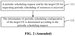
- FIG. 2 is a flowchart illustrating another method for adjusting information transmission according to an exemplary embodiment.
- Step 11 may include the following operations.
- a periodic scheduling request sent by the target UE for requesting periodic scheduling of resources is received, the periodic scheduling request at least including: an identity of the target UE and information of the periodic scheduling request.
- the information of the periodic scheduling request is information that is sent by the target UE to request the base station to start periodic scheduling for the target UE and also is information about how to periodically schedule transmission resources.
- the information of the periodic scheduling request may be expressed in at least three forms according to different contents.
- the information of the periodic scheduling request may be switch information for instructing to open a periodic scheduling mode, which for example, may be a 1-bit value representing activation of the periodic scheduling mode, such as 1.
- the information of the periodic scheduling request may include: a cycle length, the amount of and an arrangement order of time windows within the cycle length, and a time-frequency range of a BWP corresponding to each time window.
- the information of the periodic scheduling request may include: window numbers of preset BWP time-frequency resource windows and ranking information of the window numbers.
- the base station may preset a certain number of BWP time-frequency resource windows according to a protocol. For example, there are 8 different BWP time-frequency resource windows, each BWP time-frequency resource window has a fixed window number, and each BWP time-frequency resource window has a preset frequency range and window duration.
- the above information of the periodic scheduling request may include window numbers: 1, 2, and 8. It means that the target UE expects to include three BWP time-frequency resource windows in a scheduling period configured by the base station for the target UE, which are: BWP1, BWP2, and BWP8, and the above three sub-windows are arranged in a period according to a preset time sequence such as a sequential order, that is, BWP1, BWP2 and BWP8 are scheduled sequentially in the above period.
- step 112 the information of periodic-scheduling configuration of the target UE is determined according to the periodic scheduling request.
- the base station may determine the above information of periodic-scheduling configuration according to different contents of the received periodic scheduling request in any of the following manners:
- any of the following manners can be included: In the first manner, a preset configuration information list is queried according to the equipment information of the target UE to determine the information of periodic-scheduling configuration corresponding to the target UE.
- a preset configuration information list is stored in the base station, and the preset configuration information list includes a correspondence between an identity of UE and information of periodic-scheduling configuration.
- the information of periodic-scheduling configuration corresponding to UE1 is first periodic configuration information.
- the base station may be pre-configured with different information of periodic-scheduling configuration corresponding to different device types.
- the base station may determine a device type of the target UE, such as a certain type of IoT device, according to the identity of the target device, and then determine information of periodic-scheduling configuration according to the device type of the target UE.
- appropriate information of periodic-scheduling configuration may be determined according to the historical service transmission of the target UE.
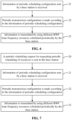
- FIG. 3 is a flowchart illustrating another method for adjusting information transmission according to an exemplary embodiment.
- Step 11 may include the following operations.
- step 11-1 a service transmission record of the target UE within a preset historical duration is acquired.
- the base station may acquire a service transmission record of a preset historical duration.
- the target UE may act as UE1
- the base station may acquire the service transmission record of UE1 recorded in the previous three months.
- step 11-2 according to the service transmission record, a transmission ratio of different types of services within a period is calculated.
- the base station may calculate the transmission ratio of the target device to transmit each service data within a period of time, such as one week or every day, according to the service transmission records in the above three months. It may be assumed that the statistical result is: a ratio of an average traffic W1 transmitted by UE1 per unit time within a first period t1 such as 0:00-6:00 one day to an average traffic W2 transmitted per unit time within left time namely a second period t2 such as 6:00-24:00 is 1:3.
- step 11-3 the information of periodic-scheduling configuration is determined according to the transmission ratio.
- the base station may determine the information of periodic-scheduling configuration according to the ratio of W1 to W2.
- the information of periodic-scheduling configuration may include a cycle length: 1 day.
- BWP1 may be scheduled in a first period t1;
- BWP2 may be scheduled in a second period t2;
- a bandwidth ratio of BWP1 to BWP2 is 1: 3.
- the historical service data transmission record of the target UE may be used to calculate the change rule of service transmission in the time period, so as to determine the information of periodic-scheduling configuration according to the change rule of service transmission in the time period, thereby improving the intelligence of the base station.
- step 12 the information of periodic-scheduling configuration is sent to the target UE to enable the target UE to make periodic-transmission configuration.
- the base station may send the above information of periodic-scheduling configuration to the target UE to instruct the target UE to configure transmission parameters in different time windows, such as adjusting a range of working frequencies, so that the target UE can acquire its own DCI and transmission resources from different BWP time-frequency resources periodically scheduled by the base station.
- the base station may send the above information of periodic-scheduling configuration to the target UE through BWP0.
- the base station may send the above information of periodic-scheduling configuration to the target UE through broadcast signaling, upper layer signaling, or physical downlink control channel (PDCCH) signaling of a physical layer.
- the upper layer signaling may be radio resource control (RRC) signaling or a medium access control (MAC) control element (CE).
- step 13 according to the information of periodic-scheduling configuration, the target UE is periodically scheduled on different BWPs for information transmission.
- the base station may periodically schedule the target UE on the BWPs corresponding to different time windows according to the above cycle length T, specifically including: periodically configuring CORESET information on different BWPs, configuring DCI belonging to the target UE in the CORESET, allocating transmission resources to the target UE according to the DCI of the target UE, and using the above transmission resources to achieve information transmission with the target UE.
- FIG. 4-1 is a schematic diagram of an application scenario for adjusting information transmission according to an exemplary embodiment. It may be assumed that a time window with a cycle length T includes two sub-windows, respectively: a first time window with a duration t1, and a second time window with a duration t2.
- the base station may schedule the target UE on BWP1; and in the second time window, the base station may schedule the target UE on BWP2.
- the base station may schedule the target UE periodically on different BWPs according to the above periodic scheduling mode, so as to satisfy the objective that the target UE can transmit different amounts of service data or different service data in different periods.
- the frequency ranges of BWP1 and BWP2 are different.
- the frequency ranges of BWPs corresponding to different time windows may also have overlapping portions, that is, the frequency range of one or more BWPs scheduled within the cycle length T is determined after being enlarged or shortened with reference to the frequency range of one of the BWPs within the period.
- the target UE can be informed of the part of the referenced BWP information of transmission configuration only, such as the time-frequency position of the CORESET, thereby reducing the data volume of the information of periodic-scheduling configuration and saving control signaling overheads.
- FIG. 4-2 is a schematic diagram of another application scenario for adjusting information transmission according to an exemplary embodiment.
- BWP2 may be determined after adjusting the frequency range based on BWP1.
- Part of BWP1 may transmit configuration information such as a time-frequency position of the CORESET, which may be used as prior information in BWP2.
- the base station does not need to instruct the target UE to make re-configuration, thereby saving signaling overheads.
- periodic scheduling for the target UE may also be cancelled.
- FIG. 5 is a flowchart illustrating another method for adjusting information transmission according to an exemplary embodiment. On the basis of the embodiment shown in FIG. 1 , after step 13, the method may include the following steps.
- step 14 information of periodic scheduling cancellation is sent to the target UE under a preset trigger condition, and periodic scheduling for the target UE is cancelled.
- the above preset trigger condition may be receiving of a periodic scheduling cancellation request from the target UE, or ending of timing of the preset periodic scheduling.
- the information of periodic scheduling cancellation may include, in addition to cancellation indication information, information of transmission configuration of subsequently scheduled BWPs after the periodic scheduling is cancelled.
- the above subsequent scheduling may be new periodic scheduling with different cycle lengths, or may be aperiodic scheduling.
- the base station may also specify information of transmission configuration of one of the BWPs, such as BWP1 or BWP2 in FIG. 4-1 , in the current scheduling period, as the information of transmission configuration of the subsequently scheduled BWPs, or may instruct the target UE to restore the transmission configuration before the periodic scheduling is carried out, such as the transmission configuration of BWP0, so that the target UE can resume the transmission configuration according to the prior information of transmission configuration, thereby reducing the data volume of information of transmission configuration and the occupied transmission resources, and saving signaling overheads accordingly.
- the current periodic scheduling may be stopped immediately, or may be cancelled after the current periodic scheduling is completed.
- the base station may determine and send information of periodic-scheduling configuration to the UE, and schedule BWPs of different bandwidths in a time period T according to the information of periodic-scheduling configuration for transmitting service data with a large change in the data volume of target UE in different periods, thereby reasonably utilizing wireless transmission resources.
- the base station since the target UE is enabled to configure information of transmission configuration of different BWPs in different time windows through one piece of information of periodic-scheduling configuration, the base station does not need to send deactivation/activation control information to the target UE for multiple times in one cycle length T to achieve period handover on multiple BWPs, thereby saving control signaling overheads, improving the efficiency of BWP handover, effectively shortening the transmission delay caused by BWP handover, enhancing the efficiency of information transmission, and improving user experience in use of a 5G NR network device.
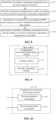
- FIG. 6 is a flowchart illustrating a method for adjusting information transmission according to an exemplary embodiment. The method may include the following steps.
- step 21 information of periodic-scheduling configuration sent by a base station is received, the information of periodic-scheduling configuration being used for instructing the UE to transmit service data periodically through at least two BWPs.
- step 22 periodic-transmission configuration is made according to the information of periodic-scheduling configuration.
- the target UE may make, according to the information of periodic-scheduling configuration, BWP transmission configuration corresponding to the first time window before the time duration T starts, and then make corresponding BWP transmission configuration in turn when each time window arrives.
- the above transmission configuration process is as follows: when the cycle length T is about to start, the UE searches for its own DCI according to a CORESET time-frequency position of BWP1, uplink and downlink transmissions are performed respectively by using uplink and downlink transmission resources allocated by the base station according to scheduling control information included in the DCI, and after the first time window t1 ends, the transmission configuration of BWP2 is performed in the same manner, and so on.
- the base station does not need to re-send control signaling for deactivating BWP1 and activating BWP2, which saves signaling overheads.
- step 23 information is transmitted by using different BWP time-frequency resources scheduled periodically by the base station.
- FIG. 7 is a flowchart illustrating another method for adjusting information transmission according to an exemplary embodiment. On the basis of the embodiment shown in FIG. 6 , before step 21, the method may include the following steps.
- a periodic scheduling request for requesting periodic scheduling of resources is sent to the base station, the periodic scheduling request at least including: an identity of the UE and information of the periodic scheduling request.
- Step 20 corresponds to step 111 and is applicable to a case where the UE initiatively requests the base station to perform periodic scheduling.
- the information of the periodic scheduling request may be expressed in the above three forms, which will not be repeated here.
- FIG. 8 is a flowchart illustrating another method for adjusting information transmission according to an exemplary embodiment. On the basis of the embodiment shown in FIG. 6 , the method may include the following steps.
- step 24 information of periodic scheduling cancellation sent by the base station is received, and periodic information transmission is cancelled.
- the step corresponds to step 14.
- the target UE may immediately cancel the periodic transmission according to the above information of periodic scheduling cancellation, or stop transmitting the service data periodically after completing the current scheduling period.
- the transmission configuration and the information transmission may be performed according to the information of subsequent BWP configuration instructed by the base station.
- the target UE may implement multiple handovers between different BWPs within a scheduling cycle length T according to the information of periodic-scheduling configuration issued by the base station once, which can effectively improve the BWP handover efficiency of the UE and save the overheads of signaling for indicating BWP handover, while avoiding waste of resources caused by the target UE using inappropriate bandwidth resources or avoiding excessively long delays in transmission of delay-sensitive services, and effectively improving user experience in use of the UE in 5G NR networks.
- the present disclosure also provides embodiments of an apparatus and a corresponding terminal for application function implementations.
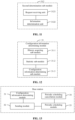
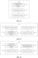
- FIG. 9 is a block diagram illustrating a base station according to an exemplary embodiment.
- the base station may include: a configuration information determining module 31, a sending module 32 and a periodic scheduling module 33.
- the configuration information determining module 31 is configured to determine information of periodic-scheduling configuration of target UE, the information of periodic-scheduling configuration being used for instructing the target UE to transmit service data periodically through at least two different BWPs.
- the information of periodic-scheduling configuration may include: a preset cycle length, at least two time windows arranged in a preset order within the cycle length, and information of transmission configuration of a BWP corresponding to each of the at least two time windows.
- the information of transmission configuration of the BWP may include: a frequency range, and a time-frequency position of a CORESET.
- the configuration information determining module 31 may be configured to query a preset configuration list according to the identity of the target UE, and acquire information of periodic-scheduling configuration corresponding to the identity of the target UE, the preset configuration list including: a correspondence between an identity of UE and information of periodic-scheduling configuration.
- the sending module 32 is configured to send the information of periodic-scheduling configuration to the target UE to enable the target UE to make periodic-transmission configuration.
- the periodic scheduling module 33 is configured to periodically schedule, according to the information of periodic-scheduling configuration, the target UE on different BWPs for information transmission.
- FIG. 10 is a block diagram illustrating another base station according to an exemplary embodiment.
- the configuration information determining module 31 may include: a first determination sub-module 311 or a second determination sub-module 312.
- the first determination sub-module 311 is configured to determine the information of periodic-scheduling configuration initiatively under a preset trigger condition.
- the second determination sub-module 312 is configured to determine the information of periodic-scheduling configuration in response to a periodic scheduling request of the target UE.
- FIG. 11 is a block diagram illustrating another base station, according to an exemplary embodiment.
- the second determination sub-module 312 may include: a request receiving unit 3121 and an information determination unit 3122.
- the request receiving unit 3121 is configured to receive a periodic scheduling request sent by the target UE for requesting periodic scheduling of resources, the periodic scheduling request at least including: an identity of the target UE and information of the periodic scheduling request.
- the information of the periodic scheduling request received by the request receiving unit 3121 may include: a cycle length, the amount of and an arrangement order of time windows within the cycle length, and a time-frequency range of a BWP corresponding to each of the time windows.
- the information of the periodic scheduling request received by the request receiving unit 3121 may include: window numbers of preset time-frequency resource windows and ranking information of the window numbers.
- the information determination unit 3122 is configured to determine the information of periodic-scheduling configuration of the target UE according to the periodic scheduling request.
- the information determination unit 3122 may be configured to generate the information of periodic-scheduling configuration according to the information of the periodic scheduling request.
- FIG. 12 is a block diagram illustrating another base station according to an exemplary embodiment.
- the configuration information determining module 31 may include: a history acquiring sub-module 31-1, a statistic sub-module 31-2 and a configuration information determining sub-module 31-3.
- the history acquiring sub-module 31-1 is configured to acquire a service transmission record of the target UE within a preset historical duration.
- the statistic sub-module 31-2 is configured to calculate, according to the service transmission record, a transmission ratio of different types of services within a period.
- the configuration information determining sub-module 31-3 is configured to determine the information of periodic-scheduling configuration according to the transmission ratio.
- FIG. 13 is a block diagram illustrating another base station according to an exemplary embodiment.
- the base station may further include: a periodic scheduling cancellation module 34.
- the periodic scheduling cancellation module 34 is configured to send information of periodic scheduling cancellation to the target UE under a preset trigger condition, and cancel periodic scheduling for the target UE.
- the information of periodic scheduling cancellation may include: information of transmission configuration of subsequently scheduled BWPs.
- the information of transmission configuration of the subsequently scheduled BWPs may include: information of transmission configuration of the BWP contained in the information of periodic-scheduling configuration.
- FIG. 14 is a block diagram illustrating UE according to an exemplary embodiment.
- the UE may include: a configuration information receiving module 41, a configuration module 42 and a transmission module 43.
- the configuration information receiving module 41 is configured to receive information of periodic-scheduling configuration sent by a base station, the information of periodic-scheduling configuration being used for instructing the UE to transmit different service data periodically through at least two BWPs.
- the configuration module 42 is configured to make periodic-transmission configuration according to the information of periodic-scheduling configuration.
- the transmission module 43 is configured to transmit information by using different BWP time-frequency resources scheduled periodically by the base station.
- FIG. 15 is a block diagram illustrating another base station according to an exemplary embodiment.
- the UE may further include: a request sending module 40.
- the request sending module 40 is configured to send a periodic scheduling request for requesting periodic scheduling of resources to the base station, the periodic scheduling request at least including: an identity of the UE and information of the periodic scheduling request.
- the information of the periodic scheduling request sent by the request sending module 40 may include: a cycle length, the amount of and an arrangement order of time windows within the cycle length, and a time-frequency range of a BWP corresponding to each time window.
- the information of the periodic scheduling request sent by the request sending module 40 may include: window numbers of preset BWP time-frequency resource windows and ranking information of the window numbers.
- FIG. 16 is a block diagram illustrating another base station according to an exemplary embodiment.
- the UE may further include: a periodic transmission cancellation module 44.
- the periodic transmission cancellation module 44 is configured to receive information of periodic scheduling cancellation sent by the base station, and cancel periodic information transmission.
- the apparatus embodiments substantially correspond to the method embodiments, and thus related parts refer to part of descriptions of the method embodiments.
- the apparatus embodiments described above are only schematic, units described as separate parts therein may or may be not physically separated, and parts displayed as units may or may be not physical units, and namely may be located in the same place or may be distributed to multiple network units. Part or all of the modules therein may be selected according to a practical requirement to achieve the solutions of the present disclosure. Those of ordinary skill in the art may understand and implement without creative work.
- a base station which includes:
- Another aspect provides UE, which includes:
- FIG. 17 is a structural schematic diagram of a base station 1700 according to an exemplary embodiment.
- the base station may be applied to a 5G NR network.
- the base station 1700 includes a processing component 1722, a wireless transmission/receiving component 1724, an antenna component 1717 and a wireless interface-specific signal processing part, and the processing component 1722 may further include one or more processors.
- One processor in the processing component 1722 may be configured to:
- non-transitory computer readable storage medium having computer instructions stored thereon.
- the computer instructions may be executed by the processing component 1722 of the base station 1700 to complete the method for adjusting information transmission in any of FIG. 1 to FIG. 5 .
- the non-transitory computer-readable storage medium may be a ROM, a random access memory (RAM), a CD-ROM, a magnetic tape, a floppy disc, an optical data storage device and the like.
- FIG. 18 is a structural schematic diagram illustrating UE 1800 according to an exemplary embodiment.
- the UE 1800 may be a terminal in a 5G NR network, and may specifically be a mobile phone, a computer, a digital broadcast terminal, a messaging device, a gaming console, a tablet, a medical device, exercise equipment, a personal digital assistant, or a wearable device such as a smart watch, smart glasses, a smart bracelet and smart running shoes.
- the apparatus 1800 may include one or more of the following components: a processing component 1802, a memory 1804, a power component 1806, a multimedia component 1808, an audio component 1810, an input/output (I/O) interface 1812, a sensor component 1814, and a communication component 1816.
- a processing component 1802 a memory 1804, a power component 1806, a multimedia component 1808, an audio component 1810, an input/output (I/O) interface 1812, a sensor component 1814, and a communication component 1816.
- the processing component 1802 is typically configured to control overall operations of the apparatus 1800, such as the operations associated with display, telephone calls, data communications, camera operations, and recording operations.
- the processing component 1802 may include one or more processors 1820 to execute instructions to perform all or part of the steps in the above described methods.
- the processing component 1802 may include one or more modules which facilitate the interaction between the processing component 1802 and other components.
- the processing component 1802 may include a multimedia module to facilitate the interaction between the multimedia component 1808 and the processing component 1802.
- the memory 1804 is configured to store various types of data to support the operation of the apparatus 1800. Examples of such data include instructions for any applications or methods operated on the apparatus 1800, contact data, phonebook data, messages, pictures, video, etc.
- the memory 1804 may be implemented using any type of volatile or non-volatile memory devices, or a combination thereof, such as a static random access memory (SRAM), an electrically erasable programmable read-only memory (EEPROM), an erasable programmable read-only memory (EPROM), a programmable read-only memory (PROM), a read-only memory (ROM), a magnetic memory, a flash memory, a magnetic or optical disk.
- SRAM static random access memory
- EEPROM electrically erasable programmable read-only memory
- EPROM erasable programmable read-only memory
- PROM programmable read-only memory
- ROM read-only memory
- magnetic memory a magnetic memory
- flash memory a flash memory
- magnetic or optical disk a magnetic or optical
- the power component 1806 may provide power to various components of the apparatus 1800.
- the power component 1806 may include a power management system, one or more power sources, and any other components associated with the generation, management, and distribution of power in the apparatus 1800.
- the multimedia component 1808 may include a screen for providing an output interface between the apparatus 1800 and the user.
- the screen may include a liquid crystal display (LCD) and a touch panel (TP). If the screen includes the TP, the screen may be implemented as a touch screen to receive an input signal from the user.
- the TP includes one or more touch sensors to sense touches, swipes and gestures on the TP. The touch sensors may not only sense a boundary of a touch or swipe action but also detect a duration and pressure associated with the touch or swipe action.
- the multimedia component 1808 may include a front camera and/or a rear camera.
- the front camera and/or the rear camera may receive external multimedia data when the device 1800 is in an operation mode, such as a photographing mode or a video mode.
- an operation mode such as a photographing mode or a video mode.
- Each of the front camera and the rear camera may be a fixed optical lens system or have focusing and optical zooming capabilities.
- the audio component 1810 is configured to output and/or input audio signals.
- the audio component 1810 includes a microphone (MIC) configured to receive an external audio signal when the apparatus 1800 is in an operation mode, such as a call mode, a recording mode, and a voice recognition mode.
- the received audio signal may be further stored in the memory 1804 or transmitted via the communication component 1816.
- the audio component 1810 further includes a speaker to output audio signals.
- the I/O interface 1812 is configured to provide an interface between the processing component 1802 and peripheral interface modules, such as a keyboard, a click wheel, buttons, and the like.
- the buttons may include, but are not limited to, a home button, a volume button, a starting button, and a locking button.
- the sensor component 1814 may include one or more sensors to provide status assessments of various aspects of the apparatus 1800. For instance, the sensor component 1814 may detect an on/off status of the device 1800 and relative positioning of components, such as a display and small keyboard of the device 1800, and the sensor component 1814 may further detect a change in a position of the device 1800 or a component of the device 1800, presence or absence of contact between the user and the device 1800, orientation or acceleration/deceleration of the device 1800 and a change in temperature of the device 1800.
- the sensor component 1814 may include a proximity sensor configured to detect presence of an object nearby without any physical contact.
- the sensor component 1814 may also include a light sensor, such as a complementary metal oxide semiconductor (CMOS) or charge coupled device (CCD) image sensor, configured for use in an imaging application.
- CMOS complementary metal oxide semiconductor
- CCD charge coupled device
- the sensor component 1814 may also include an acceleration sensor, a gyroscope sensor, a magnetic sensor, a pressure sensor or a temperature sensor.
- the communication component 1816 is configured to facilitate communication, wired or wirelessly, between the apparatus 1800 and other devices.
- the apparatus 1800 can access a wireless network based on a communication standard, such as WiFi, 2G, or 3G, or a combination thereof.
- the communication component 1816 receives a broadcast signal or broadcast associated information from an external broadcast management system via a broadcast channel.
- the communication component 1816 further includes a near field communication (NFC) module to facilitate short-range communications.
- the NFC module may be implemented based on a radio frequency identification (RFID) technology, an infrared data association (IrDA) technology, an ultra-wideband (UWB) technology, a Bluetooth (BT) technology, and other technologies.
- RFID radio frequency identification
- IrDA infrared data association
- UWB ultra-wideband
- BT Bluetooth
- the apparatus 1800 may be implemented with one or more application specific integrated circuits (ASICs), digital signal processors (DSPs), digital signal processing devices (DSPDs), programmable logic devices (PLDs), field programmable gate arrays (FPGAs), controllers, micro-controllers, microprocessors, or other electronic components, for performing the above described methods.
- ASICs application specific integrated circuits
- DSPs digital signal processors
- DSPDs digital signal processing devices
- PLDs programmable logic devices
- FPGAs field programmable gate arrays
- controllers micro-controllers, microprocessors, or other electronic components, for performing the above described methods.
- non-transitory computer readable storage medium including instructions, such as included in the memory 1804, executable by the processor 1820 in the apparatus 1800, for performing the method for adjusting information transmission in any of FIG. 6 to FIG. 8 .
- the non-transitory computer-readable storage medium may be a ROM, a RAM, a CD-ROM, a magnetic tape, a floppy disc, an optical data storage device and the like.
Landscapes
- Engineering & Computer Science (AREA)
- Signal Processing (AREA)
- Computer Networks & Wireless Communication (AREA)
- Mobile Radio Communication Systems (AREA)
Claims (15)
- Ein Verfahren zum Anpassen einer Informationsübertragung, dadurch gekennzeichnet, dass das Verfahren, das von einer Basisstation implementiert wird, umfasst:Bestimmen (11) von Informationen zur Konfiguration der periodischen Planung einer Ziel-Benutzerausrüstung, UE, wobei die Informationen zur Konfiguration der periodischen Planung verwendet werden, um die Ziel-UE anzuweisen, Dienstdaten, die unterschiedliche Datenvolumen aufweisen, periodisch über mindestens zwei unterschiedliche Bandbreitenteile, BWPs, die unterschiedliche Bandbreiten aufweisen, zu übertragen;Senden (12) der Informationen zur Konfiguration der periodischen Planung an die Ziel-UE, und Unterlassen des mehrmaligen Sendens von Deaktivierungs- oder Aktivierungssteuerungsinformationen über Deaktivierung oder Aktivierung von BWP innerhalb einer voreingestellten Zykluslänge, die in den Informationen zur Konfiguration der periodischen Planung angegeben ist, an die Ziel-UE, um es der Ziel-UE zu ermöglichen, eine Konfiguration der periodischen Übertragung vorzunehmen;Planen von BWPs unterschiedlicher Bandbreiten innerhalb der voreingestellten Zykluslänge gemäß den Informationen zur Konfiguration der periodischen Planung zum Übertragen der Dienstdaten bei einer großen Änderung der Datenvolumen der Ziel-UE in unterschiedlichen Zeitperioden; undperiodisches Planen (13) der Ziel-UE auf unterschiedlichen BWPs für die Informationsübertragung gemäß den Informationen zur Konfiguration der periodischen Planung.
- Das Verfahren nach Anspruch 1, wobei die Informationen zur Konfiguration der periodischen Planung umfassen:die voreingestellte Zykluslänge, mindestens zwei Zeitfenster, die in einer voreingestellten Reihenfolge innerhalb der voreingestellten Zykluslänge angeordnet sind, und Informationen zur Übertragungskonfiguration eines BWP, der jedem der mindestens zwei Zeitfenster entspricht;wobei die Informationen zur Übertragungskonfiguration des BWP umfassen: einen Frequenzbereich und eine Zeit-Frequenz-Position eines Steuerressourcensatzes, CORESET.
- Das Verfahren nach Anspruch 1, wobei das Bestimmen von Informationen zur Konfiguration der periodischen Planung einer Ziel-UE umfasst:initiatives Bestimmen der Informationen zur Konfiguration der periodischen Planung unter einer voreingestellten Auslösebedingung; oderBestimmen der Informationen zur Konfiguration der periodischen Planung in Reaktion auf eine periodische Planungsanforderung der Ziel-UE.
- Das Verfahren nach Anspruch 3, wobei das Bestimmen der Informationen zur Konfiguration der periodischen Planung als Reaktion auf eine periodische Planungsanforderung der Ziel-UE umfasst:Empfangen der periodischen Planungsanforderung von der Ziel-UE zum Anfordern einer periodischen Planung von Ressourcen, wobei die periodische Planungsanforderung mindestens eine Identität der Ziel-UE und Informationen der periodischen Planungsanforderung umfasst; undBestimmen der Informationen zur Konfiguration der periodischen Planung der Ziel-UE gemäß der periodischen Planungsanforderung.
- Das Verfahren nach Anspruch 4, wobeidie Informationen der periodischen Planungsanforderung umfassen: eine Zykluslänge, die Menge und eine Anordnungsreihenfolge von Zeitfenstern innerhalb der Zykluslänge und einen Zeit-Frequenz-Bereich eines BWP, der jedem der Zeitfenster entspricht; oder wobeidie Informationen der periodischen Planungsanforderung umfassen: eine voreingestellte Zeit-Frequenz-Ressourcenfensternummer und Rangfolgeinformationen der Fensternummern.
- Das Verfahren nach Anspruch 5, wobei das Bestimmen der Informationen zur Konfiguration der periodischen Planung der Ziel-UE gemäß der periodischen Planungsanforderung umfasst:Erzeugen der Informationen zur Konfiguration der periodischen Planung gemäß den Informationen der periodischen Planungsanforderung.
- Das Verfahren nach Anspruch 3, wobeidas Bestimmen von Informationen zur Konfiguration der periodischen Planung umfasst:Abfragen einer voreingestellten Konfigurationsliste gemäß einer Identität der Ziel-UE, und Erfassen von Informationen zur Konfiguration der periodischen Planung, die der Identität der Ziel-UE entsprechen,wobei die voreingestellte Konfigurationsliste umfasst: eine Entsprechung zwischen einer Identität der UE und Informationen zur Konfiguration der periodischen Planung;oder wobeidas Bestimmen von Informationen zur Konfiguration der periodischen Planung umfasst:Erfassen eines Dienstübertragungsdatensatzes der Ziel-UE innerhalb einer voreingestellten historischen Dauer;Berechnen eines Übertragungsverhältnisses unterschiedlicher Diensttypen innerhalb einer Periode gemäß dem Dienstübertragungsdatensatz; undBestimmen der Informationen zur Konfiguration der periodischen Planung gemäß dem Übertragungsverhältnis.
- Das Verfahren nach Anspruch 1, weiter umfassend:
Senden von Informationen zur Stornierung der periodischen Planung an die Ziel-UE unter einer voreingestellten Auslösebedingung, und Stornieren der periodischen Planung für die Ziel-UE. - Das Verfahren nach Anspruch 8, wobei die Informationen zur Stornierung der periodischen Planung umfassen: Informationen zur Übertragungskonfiguration von anschließend geplanten BWPs.
- Das Verfahren nach Anspruch 9, wobei die Informationen zur Übertragungskonfiguration der anschließend geplanten BWPs umfassen: Informationen zur Übertragungskonfiguration des BWP, der in den Informationen zur Konfiguration der periodischen Planung enthalten ist.
- Ein Verfahren zum Anpassen einer Informationsübertragung, dadurch gekennzeichnet, dass das Verfahren, das von einer Benutzerausrüstung, UE, implementiert wird, umfasst:Empfangen (21) von Informationen zur Konfiguration der periodischen Planung von einer Basisstation, ohne Deaktivierungs- oder Aktivierungssteuerungsinformationen über Deaktivierung oder Aktivierung von BWP mehrmals innerhalb einer voreingestellten Zykluslänge, die in den Informationen zur Konfiguration der periodischen Planung angegeben ist, zu empfangen, wobei die Informationen zur Konfiguration der periodischen Planung verwendet werden, um die UE anzuweisen, unterschiedliche Dienstdaten, die unterschiedliche Datenvolumen aufweisen, periodisch über mindestens zwei Bandbreitenteile, BWPs, die unterschiedliche Bandbreiten aufweisen, zu übertragen;Vornehmen (22) einer Konfiguration der periodischen Übertragung gemäß den Informationen zur Konfiguration der periodischen Planung; undÜbertragen (23) von Informationen unter Verwendung unterschiedlicher BWP-Zeit-Frequenz-Ressourcen, die von der Basisstation periodisch geplant werden.
- Das Verfahren nach Anspruch 11, wobei das Verfahren vor dem Empfangen von Informationen zur Konfiguration der periodischen Planung von einer Basisstation weiter umfasst:
Senden einer periodischen Planungsanforderung zum Anfordern der periodischen Planung von Ressourcen an die Basisstation, wobei die periodische Planungsanforderung mindestens umfasst: eine Identität der UE und Informationen der periodischen Planungsanforderung. - Das Verfahren nach Anspruch 12, wobeidie Informationen der periodischen Planungsanforderung umfassen: eine Zykluslänge, die Menge und eine Anordnungsreihenfolge von Zeitfenstern innerhalb der Zykluslänge und einen Zeit-Frequenz-Bereich eines BWP, der jedem Zeitfenster entspricht; oderdie Informationen der periodischen Planungsanforderung umfassen: Fensternummern von voreingestellten BWP-Zeit-Frequenz-Ressourcenfenstern und Rangfolgeinformationen der Fensternummern.
- Das Verfahren nach Anspruch 11, weiter umfassend:
Empfangen von Informationen zur Stornierung der periodischen Planung von der Basisstation, und Stornieren der periodischen Informationsübertragung. - Eine Vorrichtung, umfassend:einen Prozessor; undeinen Speicher, der dazu konfiguriert ist, eine ausführbare Anweisung des Prozessors zu speichern,wobei der Prozessor dazu konfiguriert ist, die Anweisung auszuführen, um es der Vorrichtung zu ermöglichen, die Operationen des Verfahrens nach einem der Ansprüche 1-10 oder des Verfahrens nach einem der Ansprüche 11-14 zu implementieren.
Applications Claiming Priority (1)
| Application Number | Priority Date | Filing Date | Title |
|---|---|---|---|
| PCT/CN2017/096903 WO2019028768A1 (zh) | 2017-08-10 | 2017-08-10 | 调整信息传输的方法、基站及用户设备 |
Publications (3)
| Publication Number | Publication Date |
|---|---|
| EP3661284A1 EP3661284A1 (de) | 2020-06-03 |
| EP3661284A4 EP3661284A4 (de) | 2021-01-20 |
| EP3661284B1 true EP3661284B1 (de) | 2025-03-12 |
Family
ID=65272885
Family Applications (1)
| Application Number | Title | Priority Date | Filing Date |
|---|---|---|---|
| EP17920915.0A Active EP3661284B1 (de) | 2017-08-10 | 2017-08-10 | Verfahren zur informationsübertragungseinstellung, basisstation und benutzergerät |
Country Status (5)
| Country | Link |
|---|---|
| US (1) | US11638271B2 (de) |
| EP (1) | EP3661284B1 (de) |
| CN (1) | CN109451820B (de) |
| ES (1) | ES3018479T3 (de) |
| WO (1) | WO2019028768A1 (de) |
Families Citing this family (6)
| Publication number | Priority date | Publication date | Assignee | Title |
|---|---|---|---|---|
| EP3755083B1 (de) * | 2018-02-12 | 2024-12-11 | Beijing Xiaomi Mobile Software Co., Ltd. | Verfahren zur übertragung von informationen und basisstation |
| EP4017190B1 (de) | 2019-09-18 | 2023-10-25 | Guangdong Oppo Mobile Telecommunications Corp., Ltd. | Ressourcenkonfigurationsverfahren und zugangsnetzwerkvorrichtung |
| CN114007225A (zh) * | 2020-07-28 | 2022-02-01 | 北京三星通信技术研究有限公司 | Bwp的分配方法、装置、电子设备及计算机可读存储介质 |
| WO2022151411A1 (zh) * | 2021-01-15 | 2022-07-21 | 华为技术有限公司 | Bwp的激活方法及通信装置 |
| CN115707014A (zh) * | 2021-08-13 | 2023-02-17 | 华为技术有限公司 | 通信方法及装置 |
| CN115714995A (zh) * | 2021-08-20 | 2023-02-24 | 维沃移动通信有限公司 | 工作带宽调整方法、相关设备及可读存储介质 |
Family Cites Families (6)
| Publication number | Priority date | Publication date | Assignee | Title |
|---|---|---|---|---|
| CN101626603A (zh) * | 2008-07-11 | 2010-01-13 | 北京信威通信技术股份有限公司 | 一种基于终端射频特征参数的资源分配方法及系统 |
| CN103327630B (zh) * | 2012-03-23 | 2016-12-14 | 华为技术有限公司 | 用于无线网络中的无线资源调度的方法和装置 |
| CN103580833B (zh) * | 2012-07-25 | 2018-08-14 | 上海诺基亚贝尔股份有限公司 | 一种用于配置载波聚合的方法和设备 |
| WO2014046577A1 (en) * | 2012-09-18 | 2014-03-27 | Telefonaktiebolaget L M Ericsson (Publ) | Method in a network node and method in a telecommunication system for cell edge band allocation and network node |
| KR102363662B1 (ko) * | 2017-06-16 | 2022-02-16 | 광동 오포 모바일 텔레커뮤니케이션즈 코포레이션 리미티드 | 무선 통신 방법 및 디바이스 |
| US10880949B2 (en) * | 2018-05-15 | 2020-12-29 | Comcast Cable Communications, Llc | Multiple active bandwidth parts |
-
2017
- 2017-08-10 EP EP17920915.0A patent/EP3661284B1/de active Active
- 2017-08-10 WO PCT/CN2017/096903 patent/WO2019028768A1/zh not_active Ceased
- 2017-08-10 ES ES17920915T patent/ES3018479T3/es active Active
- 2017-08-10 CN CN201780000811.3A patent/CN109451820B/zh active Active
-
2020
- 2020-02-04 US US16/781,452 patent/US11638271B2/en active Active
Also Published As
| Publication number | Publication date |
|---|---|
| CN109451820B (zh) | 2022-07-22 |
| US20200178264A1 (en) | 2020-06-04 |
| CN109451820A (zh) | 2019-03-08 |
| EP3661284A4 (de) | 2021-01-20 |
| US11638271B2 (en) | 2023-04-25 |
| EP3661284A1 (de) | 2020-06-03 |
| WO2019028768A1 (zh) | 2019-02-14 |
| ES3018479T3 (es) | 2025-05-16 |
Similar Documents
| Publication | Publication Date | Title |
|---|---|---|
| US11184829B2 (en) | Method for information transmission adjustment, base station, and user equipment | |
| US11638271B2 (en) | Method for information transmission adjustment, base station, and user equipment | |
| EP4033828B1 (de) | Kommunikationsverfahren und -vorrichtung sowie speichermedium | |
| US11445511B2 (en) | Method for information transmission adjustment, base station, and user equipment | |
| US11399383B2 (en) | Method and device for requesting uplink transmission resource | |
| EP3806527B1 (de) | Verfahren und vorrichtung zum bwp-umschalten und speichermedium | |
| EP3829251A1 (de) | Übertragungssteuerungsverfahren und -vorrichtung | |
| CN109496400B (zh) | 重传信息的方法、装置、基站及终端 | |
| CN109451794B (zh) | 传输信息的方法及装置 | |
| WO2019153348A1 (zh) | 传输信息的方法、基站及用户设备 | |
| US20220078824A1 (en) | Method for transmitting uplink information, apparatus base station and terminal | |
| KR20240125647A (ko) | 주파수 영역 리소스 결정 방법, 장치 및 저장 매체 | |
| US11895686B2 (en) | Method, device and medium for transmitting information | |
| EP3633897B1 (de) | Datenübertragungsverfahren und -vorrichtung | |
| US12004016B2 (en) | Method and apparatus for transmitting configuration information | |
| WO2024021125A1 (zh) | 上行传输切换、控制方法及装置、通信装置和存储介质 | |
| US20230337245A1 (en) | Communication method, electronic device and storage medium | |
| EP4482204A1 (de) | Verfahren und vorrichtung zur konfiguration eines bandbreitenteils, vorrichtung und speichermedium | |
| US20240381412A1 (en) | Method and apparatus for receiving and sending physical downlink shared channel, and medium |
Legal Events
| Date | Code | Title | Description |
|---|---|---|---|
| STAA | Information on the status of an ep patent application or granted ep patent |
Free format text: STATUS: THE INTERNATIONAL PUBLICATION HAS BEEN MADE |
|
| PUAI | Public reference made under article 153(3) epc to a published international application that has entered the european phase |
Free format text: ORIGINAL CODE: 0009012 |
|
| STAA | Information on the status of an ep patent application or granted ep patent |
Free format text: STATUS: REQUEST FOR EXAMINATION WAS MADE |
|
| 17P | Request for examination filed |
Effective date: 20200227 |
|
| AK | Designated contracting states |
Kind code of ref document: A1 Designated state(s): AL AT BE BG CH CY CZ DE DK EE ES FI FR GB GR HR HU IE IS IT LI LT LU LV MC MK MT NL NO PL PT RO RS SE SI SK SM TR |
|
| AX | Request for extension of the european patent |
Extension state: BA ME |
|
| RAP1 | Party data changed (applicant data changed or rights of an application transferred) |
Owner name: BEIJING XIAOMI MOBILE SOFTWARE CO., LTD. |
|
| RAP1 | Party data changed (applicant data changed or rights of an application transferred) |
Owner name: BEIJING XIAOMI MOBILE SOFTWARE CO., LTD. |
|
| RAP1 | Party data changed (applicant data changed or rights of an application transferred) |
Owner name: BEIJING XIAOMI MOBILE SOFTWARE CO., LTD. |
|
| RIN1 | Information on inventor provided before grant (corrected) |
Inventor name: ZHOU, JUEJIA |
|
| DAV | Request for validation of the european patent (deleted) | ||
| DAX | Request for extension of the european patent (deleted) | ||
| A4 | Supplementary search report drawn up and despatched |
Effective date: 20201218 |
|
| RIC1 | Information provided on ipc code assigned before grant |
Ipc: H04L 5/00 20060101ALN20201214BHEP Ipc: H04W 24/04 20090101ALN20201214BHEP Ipc: H04W 72/12 20090101ALN20201214BHEP Ipc: H04W 72/04 20090101AFI20201214BHEP |
|
| STAA | Information on the status of an ep patent application or granted ep patent |
Free format text: STATUS: EXAMINATION IS IN PROGRESS |
|
| 17Q | First examination report despatched |
Effective date: 20220215 |
|
| GRAP | Despatch of communication of intention to grant a patent |
Free format text: ORIGINAL CODE: EPIDOSNIGR1 |
|
| STAA | Information on the status of an ep patent application or granted ep patent |
Free format text: STATUS: GRANT OF PATENT IS INTENDED |
|
| RIC1 | Information provided on ipc code assigned before grant |
Ipc: H04W 72/1263 20230101ALN20241212BHEP Ipc: H04W 24/04 20090101ALN20241212BHEP Ipc: H04W 72/12 20090101ALN20241212BHEP Ipc: H04L 5/00 20060101ALN20241212BHEP Ipc: H04W 72/0453 20230101ALI20241212BHEP Ipc: H04W 72/04 20090101AFI20241212BHEP |
|
| RIC1 | Information provided on ipc code assigned before grant |
Ipc: H04W 72/1263 20230101ALN20241219BHEP Ipc: H04W 24/04 20090101ALN20241219BHEP Ipc: H04W 72/12 20090101ALN20241219BHEP Ipc: H04L 5/00 20060101ALN20241219BHEP Ipc: H04W 72/0453 20230101ALI20241219BHEP Ipc: H04W 72/04 20090101AFI20241219BHEP |
|
| GRAS | Grant fee paid |
Free format text: ORIGINAL CODE: EPIDOSNIGR3 |
|
| GRAA | (expected) grant |
Free format text: ORIGINAL CODE: 0009210 |
|
| STAA | Information on the status of an ep patent application or granted ep patent |
Free format text: STATUS: THE PATENT HAS BEEN GRANTED |
|
| INTG | Intention to grant announced |
Effective date: 20250109 |
|
| AK | Designated contracting states |
Kind code of ref document: B1 Designated state(s): AL AT BE BG CH CY CZ DE DK EE ES FI FR GB GR HR HU IE IS IT LI LT LU LV MC MK MT NL NO PL PT RO RS SE SI SK SM TR |
|
| REG | Reference to a national code |
Ref country code: GB Ref legal event code: FG4D |
|
| REG | Reference to a national code |
Ref country code: CH Ref legal event code: EP |
|
| REG | Reference to a national code |
Ref country code: DE Ref legal event code: R096 Ref document number: 602017088351 Country of ref document: DE |
|
| P01 | Opt-out of the competence of the unified patent court (upc) registered |
Free format text: CASE NUMBER: APP_8612/2025 Effective date: 20250220 |
|
| REG | Reference to a national code |
Ref country code: IE Ref legal event code: FG4D |
|
| REG | Reference to a national code |
Ref country code: ES Ref legal event code: FG2A Ref document number: 3018479 Country of ref document: ES Kind code of ref document: T3 Effective date: 20250516 |
|
| PG25 | Lapsed in a contracting state [announced via postgrant information from national office to epo] |
Ref country code: RS Free format text: LAPSE BECAUSE OF FAILURE TO SUBMIT A TRANSLATION OF THE DESCRIPTION OR TO PAY THE FEE WITHIN THE PRESCRIBED TIME-LIMIT Effective date: 20250612 |
|
| PG25 | Lapsed in a contracting state [announced via postgrant information from national office to epo] |
Ref country code: FI Free format text: LAPSE BECAUSE OF FAILURE TO SUBMIT A TRANSLATION OF THE DESCRIPTION OR TO PAY THE FEE WITHIN THE PRESCRIBED TIME-LIMIT Effective date: 20250312 |
|
| REG | Reference to a national code |
Ref country code: LT Ref legal event code: MG9D |
|
| PG25 | Lapsed in a contracting state [announced via postgrant information from national office to epo] |
Ref country code: NO Free format text: LAPSE BECAUSE OF FAILURE TO SUBMIT A TRANSLATION OF THE DESCRIPTION OR TO PAY THE FEE WITHIN THE PRESCRIBED TIME-LIMIT Effective date: 20250612 |
|
| PG25 | Lapsed in a contracting state [announced via postgrant information from national office to epo] |
Ref country code: HR Free format text: LAPSE BECAUSE OF FAILURE TO SUBMIT A TRANSLATION OF THE DESCRIPTION OR TO PAY THE FEE WITHIN THE PRESCRIBED TIME-LIMIT Effective date: 20250312 |
|
| REG | Reference to a national code |
Ref country code: NL Ref legal event code: MP Effective date: 20250312 |
|
| PG25 | Lapsed in a contracting state [announced via postgrant information from national office to epo] |
Ref country code: LV Free format text: LAPSE BECAUSE OF FAILURE TO SUBMIT A TRANSLATION OF THE DESCRIPTION OR TO PAY THE FEE WITHIN THE PRESCRIBED TIME-LIMIT Effective date: 20250312 |
|
| PG25 | Lapsed in a contracting state [announced via postgrant information from national office to epo] |
Ref country code: GR Free format text: LAPSE BECAUSE OF FAILURE TO SUBMIT A TRANSLATION OF THE DESCRIPTION OR TO PAY THE FEE WITHIN THE PRESCRIBED TIME-LIMIT Effective date: 20250613 Ref country code: BG Free format text: LAPSE BECAUSE OF FAILURE TO SUBMIT A TRANSLATION OF THE DESCRIPTION OR TO PAY THE FEE WITHIN THE PRESCRIBED TIME-LIMIT Effective date: 20250312 |
|
| REG | Reference to a national code |
Ref country code: AT Ref legal event code: MK05 Ref document number: 1776071 Country of ref document: AT Kind code of ref document: T Effective date: 20250312 |
|
| PG25 | Lapsed in a contracting state [announced via postgrant information from national office to epo] |
Ref country code: NL Free format text: LAPSE BECAUSE OF FAILURE TO SUBMIT A TRANSLATION OF THE DESCRIPTION OR TO PAY THE FEE WITHIN THE PRESCRIBED TIME-LIMIT Effective date: 20250312 |
|
| PG25 | Lapsed in a contracting state [announced via postgrant information from national office to epo] |
Ref country code: SE Free format text: LAPSE BECAUSE OF FAILURE TO SUBMIT A TRANSLATION OF THE DESCRIPTION OR TO PAY THE FEE WITHIN THE PRESCRIBED TIME-LIMIT Effective date: 20250312 |
|
| PG25 | Lapsed in a contracting state [announced via postgrant information from national office to epo] |
Ref country code: SM Free format text: LAPSE BECAUSE OF FAILURE TO SUBMIT A TRANSLATION OF THE DESCRIPTION OR TO PAY THE FEE WITHIN THE PRESCRIBED TIME-LIMIT Effective date: 20250312 |
|
| PG25 | Lapsed in a contracting state [announced via postgrant information from national office to epo] |
Ref country code: PT Free format text: LAPSE BECAUSE OF FAILURE TO SUBMIT A TRANSLATION OF THE DESCRIPTION OR TO PAY THE FEE WITHIN THE PRESCRIBED TIME-LIMIT Effective date: 20250714 |
|
| PGFP | Annual fee paid to national office [announced via postgrant information from national office to epo] |
Ref country code: ES Payment date: 20250926 Year of fee payment: 9 |
|
| PG25 | Lapsed in a contracting state [announced via postgrant information from national office to epo] |
Ref country code: IT Free format text: LAPSE BECAUSE OF FAILURE TO SUBMIT A TRANSLATION OF THE DESCRIPTION OR TO PAY THE FEE WITHIN THE PRESCRIBED TIME-LIMIT Effective date: 20250312 Ref country code: PL Free format text: LAPSE BECAUSE OF FAILURE TO SUBMIT A TRANSLATION OF THE DESCRIPTION OR TO PAY THE FEE WITHIN THE PRESCRIBED TIME-LIMIT Effective date: 20250312 |
|
| PGFP | Annual fee paid to national office [announced via postgrant information from national office to epo] |
Ref country code: GB Payment date: 20250820 Year of fee payment: 9 |
|
| PG25 | Lapsed in a contracting state [announced via postgrant information from national office to epo] |
Ref country code: AT Free format text: LAPSE BECAUSE OF FAILURE TO SUBMIT A TRANSLATION OF THE DESCRIPTION OR TO PAY THE FEE WITHIN THE PRESCRIBED TIME-LIMIT Effective date: 20250312 |
|
| PGFP | Annual fee paid to national office [announced via postgrant information from national office to epo] |
Ref country code: FR Payment date: 20250828 Year of fee payment: 9 |
|
| PG25 | Lapsed in a contracting state [announced via postgrant information from national office to epo] |
Ref country code: EE Free format text: LAPSE BECAUSE OF FAILURE TO SUBMIT A TRANSLATION OF THE DESCRIPTION OR TO PAY THE FEE WITHIN THE PRESCRIBED TIME-LIMIT Effective date: 20250312 Ref country code: CZ Free format text: LAPSE BECAUSE OF FAILURE TO SUBMIT A TRANSLATION OF THE DESCRIPTION OR TO PAY THE FEE WITHIN THE PRESCRIBED TIME-LIMIT Effective date: 20250312 |
|
| PG25 | Lapsed in a contracting state [announced via postgrant information from national office to epo] |
Ref country code: RO Free format text: LAPSE BECAUSE OF FAILURE TO SUBMIT A TRANSLATION OF THE DESCRIPTION OR TO PAY THE FEE WITHIN THE PRESCRIBED TIME-LIMIT Effective date: 20250312 |
|
| PG25 | Lapsed in a contracting state [announced via postgrant information from national office to epo] |
Ref country code: SK Free format text: LAPSE BECAUSE OF FAILURE TO SUBMIT A TRANSLATION OF THE DESCRIPTION OR TO PAY THE FEE WITHIN THE PRESCRIBED TIME-LIMIT Effective date: 20250312 |
|
| PG25 | Lapsed in a contracting state [announced via postgrant information from national office to epo] |
Ref country code: IS Free format text: LAPSE BECAUSE OF FAILURE TO SUBMIT A TRANSLATION OF THE DESCRIPTION OR TO PAY THE FEE WITHIN THE PRESCRIBED TIME-LIMIT Effective date: 20250712 |