EP3661233A1 - Wearable beamforming speaker array - Google Patents
Wearable beamforming speaker array Download PDFInfo
- Publication number
- EP3661233A1 EP3661233A1 EP19210571.6A EP19210571A EP3661233A1 EP 3661233 A1 EP3661233 A1 EP 3661233A1 EP 19210571 A EP19210571 A EP 19210571A EP 3661233 A1 EP3661233 A1 EP 3661233A1
- Authority
- EP
- European Patent Office
- Prior art keywords
- speaker
- array
- speaker array
- directional sound
- target location
- Prior art date
- Legal status (The legal status is an assumption and is not a legal conclusion. Google has not performed a legal analysis and makes no representation as to the accuracy of the status listed.)
- Granted
Links
- 238000000034 method Methods 0.000 claims description 26
- 239000002131 composite material Substances 0.000 claims description 20
- 238000012545 processing Methods 0.000 description 39
- 238000010586 diagram Methods 0.000 description 13
- 230000033001 locomotion Effects 0.000 description 13
- 210000005069 ears Anatomy 0.000 description 12
- 230000008859 change Effects 0.000 description 6
- 238000004590 computer program Methods 0.000 description 6
- 230000006870 function Effects 0.000 description 6
- 238000005381 potential energy Methods 0.000 description 5
- 230000005236 sound signal Effects 0.000 description 5
- 230000001934 delay Effects 0.000 description 3
- 230000000694 effects Effects 0.000 description 3
- 210000003128 head Anatomy 0.000 description 3
- 230000003287 optical effect Effects 0.000 description 3
- 230000008447 perception Effects 0.000 description 3
- 230000008569 process Effects 0.000 description 3
- 230000008901 benefit Effects 0.000 description 2
- 238000005259 measurement Methods 0.000 description 2
- 239000000853 adhesive Substances 0.000 description 1
- 230000001070 adhesive effect Effects 0.000 description 1
- 238000003491 array Methods 0.000 description 1
- 230000003190 augmentative effect Effects 0.000 description 1
- 230000005540 biological transmission Effects 0.000 description 1
- 230000001413 cellular effect Effects 0.000 description 1
- 238000000205 computational method Methods 0.000 description 1
- 238000013461 design Methods 0.000 description 1
- 210000000613 ear canal Anatomy 0.000 description 1
- 238000013507 mapping Methods 0.000 description 1
- 230000007246 mechanism Effects 0.000 description 1
- 238000012986 modification Methods 0.000 description 1
- 230000004048 modification Effects 0.000 description 1
- 230000001537 neural effect Effects 0.000 description 1
- 239000013307 optical fiber Substances 0.000 description 1
- 230000003252 repetitive effect Effects 0.000 description 1
- 230000004044 response Effects 0.000 description 1
- 239000004065 semiconductor Substances 0.000 description 1
- 238000002604 ultrasonography Methods 0.000 description 1
- 210000000707 wrist Anatomy 0.000 description 1
Images


Classifications
-
- H—ELECTRICITY
- H04—ELECTRIC COMMUNICATION TECHNIQUE
- H04R—LOUDSPEAKERS, MICROPHONES, GRAMOPHONE PICK-UPS OR LIKE ACOUSTIC ELECTROMECHANICAL TRANSDUCERS; DEAF-AID SETS; PUBLIC ADDRESS SYSTEMS
- H04R1/00—Details of transducers, loudspeakers or microphones
- H04R1/20—Arrangements for obtaining desired frequency or directional characteristics
- H04R1/32—Arrangements for obtaining desired frequency or directional characteristics for obtaining desired directional characteristic only
- H04R1/40—Arrangements for obtaining desired frequency or directional characteristics for obtaining desired directional characteristic only by combining a number of identical transducers
- H04R1/403—Arrangements for obtaining desired frequency or directional characteristics for obtaining desired directional characteristic only by combining a number of identical transducers loud-speakers
-
- H—ELECTRICITY
- H04—ELECTRIC COMMUNICATION TECHNIQUE
- H04R—LOUDSPEAKERS, MICROPHONES, GRAMOPHONE PICK-UPS OR LIKE ACOUSTIC ELECTROMECHANICAL TRANSDUCERS; DEAF-AID SETS; PUBLIC ADDRESS SYSTEMS
- H04R3/00—Circuits for transducers, loudspeakers or microphones
- H04R3/12—Circuits for transducers, loudspeakers or microphones for distributing signals to two or more loudspeakers
-
- H—ELECTRICITY
- H04—ELECTRIC COMMUNICATION TECHNIQUE
- H04R—LOUDSPEAKERS, MICROPHONES, GRAMOPHONE PICK-UPS OR LIKE ACOUSTIC ELECTROMECHANICAL TRANSDUCERS; DEAF-AID SETS; PUBLIC ADDRESS SYSTEMS
- H04R5/00—Stereophonic arrangements
- H04R5/02—Spatial or constructional arrangements of loudspeakers
-
- H—ELECTRICITY
- H04—ELECTRIC COMMUNICATION TECHNIQUE
- H04R—LOUDSPEAKERS, MICROPHONES, GRAMOPHONE PICK-UPS OR LIKE ACOUSTIC ELECTROMECHANICAL TRANSDUCERS; DEAF-AID SETS; PUBLIC ADDRESS SYSTEMS
- H04R5/00—Stereophonic arrangements
- H04R5/04—Circuit arrangements, e.g. for selective connection of amplifier inputs/outputs to loudspeakers, for loudspeaker detection, or for adaptation of settings to personal preferences or hearing impairments
-
- H—ELECTRICITY
- H04—ELECTRIC COMMUNICATION TECHNIQUE
- H04S—STEREOPHONIC SYSTEMS
- H04S7/00—Indicating arrangements; Control arrangements, e.g. balance control
- H04S7/30—Control circuits for electronic adaptation of the sound field
- H04S7/302—Electronic adaptation of stereophonic sound system to listener position or orientation
- H04S7/303—Tracking of listener position or orientation
-
- H—ELECTRICITY
- H04—ELECTRIC COMMUNICATION TECHNIQUE
- H04R—LOUDSPEAKERS, MICROPHONES, GRAMOPHONE PICK-UPS OR LIKE ACOUSTIC ELECTROMECHANICAL TRANSDUCERS; DEAF-AID SETS; PUBLIC ADDRESS SYSTEMS
- H04R2201/00—Details of transducers, loudspeakers or microphones covered by H04R1/00 but not provided for in any of its subgroups
- H04R2201/02—Details casings, cabinets or mounting therein for transducers covered by H04R1/02 but not provided for in any of its subgroups
- H04R2201/023—Transducers incorporated in garment, rucksacks or the like
-
- H—ELECTRICITY
- H04—ELECTRIC COMMUNICATION TECHNIQUE
- H04R—LOUDSPEAKERS, MICROPHONES, GRAMOPHONE PICK-UPS OR LIKE ACOUSTIC ELECTROMECHANICAL TRANSDUCERS; DEAF-AID SETS; PUBLIC ADDRESS SYSTEMS
- H04R2201/00—Details of transducers, loudspeakers or microphones covered by H04R1/00 but not provided for in any of its subgroups
- H04R2201/40—Details of arrangements for obtaining desired directional characteristic by combining a number of identical transducers covered by H04R1/40 but not provided for in any of its subgroups
- H04R2201/401—2D or 3D arrays of transducers
-
- H—ELECTRICITY
- H04—ELECTRIC COMMUNICATION TECHNIQUE
- H04R—LOUDSPEAKERS, MICROPHONES, GRAMOPHONE PICK-UPS OR LIKE ACOUSTIC ELECTROMECHANICAL TRANSDUCERS; DEAF-AID SETS; PUBLIC ADDRESS SYSTEMS
- H04R2203/00—Details of circuits for transducers, loudspeakers or microphones covered by H04R3/00 but not provided for in any of its subgroups
- H04R2203/12—Beamforming aspects for stereophonic sound reproduction with loudspeaker arrays
-
- H—ELECTRICITY
- H04—ELECTRIC COMMUNICATION TECHNIQUE
- H04R—LOUDSPEAKERS, MICROPHONES, GRAMOPHONE PICK-UPS OR LIKE ACOUSTIC ELECTROMECHANICAL TRANSDUCERS; DEAF-AID SETS; PUBLIC ADDRESS SYSTEMS
- H04R2430/00—Signal processing covered by H04R, not provided for in its groups
- H04R2430/20—Processing of the output signals of the acoustic transducers of an array for obtaining a desired directivity characteristic
Definitions
- Embodiments of the present disclosure relate generally to audio systems and, more specifically, to a wearable beamforming speaker array.
- Consumer electronics devices such as smartphones, media players, tablet computers, personal computers, virtual reality (VR) devices, and/or augmented reality (AR) devices, enable users to enjoy media content in various environments and while performing a variety of different activities.
- Such devices commonly have an audio output device that includes one or more audio transducers.
- the audio transducers emit soundwaves reproducing an audio signal that represents the audio portion of the media content. When the soundwave reaches the ears of the user, the user is able to hear the audio portion of the media content.
- the audio transducers output sound into the surrounding environment, such that the sound can be heard by others proximate to the user.
- the user may listen to the audio portion via a pair of headphones, where the audio transducers output sound towards the user's ears without outputting sound into the environment.
- headphones generally allow a user to listen to high-quality audio content privately and/or without disturbing others, such devices have several downsides. For example, when headphones are worn by a user, the headphones may occlude the user's ears, preventing the user from hearing other sounds in the environment. In addition, headphones may move out of position while a user is moving, preventing the user from hearing the audio content and/or requiring the user to repeatedly reposition the headphones. For example, while a user is exercising or performing other activities that involve movement, on-ear or over-the-ear headphones may move relative to the head of the user, and in-ear headphones may fall out of the user's ear canal.
- Embodiments of the present disclosure set forth an audio system including a speaker array including two or more speakers, one or more sensors configured to produce sensor data, and a processor coupled to the one or more sensors and the speaker array.
- the processor is configured to determine, based on the sensor data, for each speaker included in the speaker array, a position of the speaker relative to at least one of a target location, and one or more other speakers included in the speaker array, determine, based on the positions of the speakers included in the speaker array, a first set of directional sound components.
- Each directional sound component included in the first set of directional sound components is defined between a corresponding speaker and the target location.
- the processor is further configured to generate a first set of speaker signals for the speaker array based on the first set of directional sound components, where, when outputted by the speaker array, the first set of speaker signals produces an acoustic field at the target location.
- At least one advantage of the disclosed techniques is that an audio portion of media content can be provided to a user without requiring the user to wear headphones that obstruct other sounds in the surrounding environment from reaching the user.
- a composite acoustic field can be generated in a variety of different spatial configurations, despite changes to the position(s) and/or orientation(s) of individual speakers included in the speaker array.
- This adaptability of the beamforming speaker array system enables greater design flexibility, allowing the system to be implemented in a variety of different form factors.
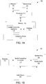
- FIG. 1A illustrates a block diagram of a beamforming speaker array system 100 configured to implement one or more aspects of the present disclosure.
- Beamforming speaker array system 100 includes computing device 110, one or more sensors 120, and speaker array 130.
- Computing device 110 includes processing unit 112 and memory 114.
- Memory 114 stores spatial computation application 116 and database 118.
- processing unit 112 receives sensor data from sensor(s) 120.
- Processing unit 112 executes spatial computation application 116 to analyze the sensor data and determine the current configuration of speaker array 130, including the positions and/or orientations of the individual speakers included in speaker array 130.
- spatial computation application 116 determines directional sound components from which speaker signals are to be emitted by each speaker included in the speaker array 130.
- the speaker signals produce a particular acoustic field at a target location, such as proximate to the ears of a user.
- spatial computation application 116 may then generate one or more sound parameters for each speaker in the speaker array 130.
- Spatial computation application 116 then generates one or more speaker signals based on the one or more sound parameters and based on an audio source signal.
- the speaker signals may then be transmitted to the speakers included in the speaker array 130, which receive the speaker signals and output sound based on the speaker signals.
- the sound outputted by the speakers (e.g. , a speaker and an amplifier) included in speaker array 130 then combines to produce a composite acoustic field at the target location.
- the target location includes the ears of a user, enabling the user to listen to a high-quality, composite acoustic field via multiple speakers that are located proximate to the user.
- the one or more sound parameters may include, without limitation, a direction in which a target is located relative to a speaker (e.g. , relative to a center axis of a speaker), a sound level to be outputted by a speaker in order to generate a desired sound level at a target location (e.g. , a target location that is off-axis relative to a speaker), a distance between a speaker and a target location, a distance and/or angle between the speaker and one or more other speakers included in the speaker array 130, a phase delay to be applied to a speaker signal in order to generate a desired acoustic field at a target location, etc.
- a direction in which a target is located relative to a speaker e.g. , relative to a center axis of a speaker
- a sound level to be outputted by a speaker in order to generate a desired sound level at a target location e.g. , a target location that is off-axis relative to a speaker
- the spatial computation application 116 could determine one or more sound parameters that include an angular direction of a target location relative to a center axis of the speaker. The spatial computation application 116 could then determine, based on the one or more sound parameters, a sound level that should be outputted by the speaker in order to generate a desired sound level at the target location.
- Sensor(s) 120 include one or more devices that detect positions of objects in an environment by performing measurements and/or collecting data.
- the one or more sensors 120 may be coupled to and/or included within individual speakers included in speaker array 130.
- computing device 110 may receive sensor data via the one or more sensors 120, where the sensor data reflects the position(s) and/or orientation(s) of one or more speakers included in speaker array 130.
- the position(s) and/or orientation(s) of the one or more speakers may be derived from the absolute position of the one or more sensors 120, or may be derived from a relative position of an object to the one or more sensors 120.
- Processing unit 112 then executes spatial computation application 116 to analyze the received sensor data to determine a current configuration of speaker array 130, including the position(s) and/or the orientation(s) of the one or more speakers.
- sensor(s) 120 may produce sensor data that is associated with the positions of portions of the user's body. For example, sensor(s) 120 may be positioned near one or more ears of the user and may produce sensor data. Processing unit 112 may analyze the sensor data to track the location of one of the user's ears, both of the user's ears, and/or the user's head based on the sensor data. The spatial computation application 116 may then determine a target location at which an acoustic field will be generated based on the location(s).
- the one or sensors 120 may include position sensors, such as an accelerometer or an inertial measurement unit (IMU).
- the IMU may be a device like a three-axis accelerometer, gyroscopic sensor, and/or magnetometer.
- sensor(s) 120 may include optical sensors, such RGB cameras, time-of-flight sensors, infrared (IR) cameras, depth cameras, and/or a quick response (QR) code tracking system.
- sensor(s) 120 may include wireless sensors, including radio frequency (RF) sensors (e.g. , sonar and radar), ultrasound-based sensors, capacitive sensors, laser-based sensors, and/or wireless communications protocols, including Bluetooth, Bluetooth low energy (BLE), wireless local area network (WiFi) cellular protocols, and/or near-field communications (NFC).
- RF radio frequency
- BLE Bluetooth low energy
- WiFi wireless local area network
- NFC near-field communications
- computing device 110 may include processing unit 112 and memory 114.
- Computing device 110 may be a device that includes one or more processing units 112, such as a system-on-a-chip (SoC), or a mobile computing device, such as a tablet computer, mobile phone, media player, and so forth.
- SoC system-on-a-chip
- computing device 110 is integrated with an individual speaker included in speaker array 130.
- computing device 110 may be configured to coordinate the overall operation of beamforming speaker array system 100.
- computing device 110 may be coupled to, but be separate from, one or more individual speakers included in speaker array 130. In such instances, computing device 110 may be included in a separate device.
- the embodiments disclosed herein contemplate any technically-feasible system configured to implement the functionality of beamforming speaker array system 100 via computing device 110.
- Processing unit 112 may include a central processing unit (CPU), a digital signal processing unit (DSP), a microprocessor, an application-specific integrated circuit (ASIC), a neural processing unit (NPU), a graphics processing unit (GPU), a field-programmable gate array (FPGA), and so forth.
- processing unit 112 may be configured to execute spatial computation application 116 in order to analyze sensor data acquired by sensor(s) 120 and determine a current configuration of speaker array 130.
- processing unit 112 may be configured to execute spatial computation application 116 to compute one or more directional sound components, where the one or more directional sound components are based on the determined current configuration of speaker array 130.
- Processing unit 112 is configured to execute spatial computation application 116 to generate one or more sound parameters based on the directional sound components.
- the one or more sound parameters include one or more parameters that cause the speaker array 130 to emit soundwaves based on the sound parameters.
- processing unit 112 is configured to generate speaker signals from the one or more sound parameters and then transmit the speaker signals to speaker array 130.
- processing unit 112 transmits the speaker signals to one or more speakers in speaker array 130 wirelessly.
- processing unit 112 executes spatial computation application 116 in order to determine sound parameters and generate speaker signals for all speakers included in the speaker array 130.
- each speaker included in speaker array 130 may include a separate processing unit that determines one or more sound parameters for that speaker and/or generates a speaker signal to be outputted by that speaker, based on the one or more sound parameters.
- each speaker may include a processing unit that executes an instance of the spatial computation application 116 in order to generate a single speaker signal for a single speaker.
- each spatial computation application 116 may also determine the current configuration of the speaker array 130 and determine one or more sound parameters for that speaker based on the configuration of the speaker array 130.
- processing unit 112 could execute spatial computation application 116 to determine one or more sound parameters for each speaker. The sound parameter(s) could then be transmitted to each speaker, and a processing unit included in each speaker could generate and output a speaker signal based on the sound parameter(s). Accordingly, although various embodiments disclosed herein are described as being performed via a processing unit 112 that executes spatial computation application 116, each of the disclosed techniques could be performed by separate processing units included in individual speakers.
- Memory 114 may include a memory module or collection of memory modules. Spatial computation application 116 within memory 114 may be executed by processing unit 112 to implement the overall functionality of the computing device 110 and, thus, to coordinate the operation of the beamforming speaker array system 100 as a whole.
- Database 118 may store values and other data retrieved by processing unit 112 to coordinate the operation of beamforming speaker array system 100.
- processing unit 112 may be configured to store values in database 118 and/or retrieve values stored in database 118.
- database 118 may store sensor data, predictive estimation values, audio content, digital signal processing algorithms, transducer parameter data, and so forth.
- the configuration of speaker array 130 may change.
- the change in the updated configuration of speaker array 130 may be due to a change in position(s) and/or orientation(s) of one or more individual speakers.
- speaker array 130 may receive updated sound parameters generated by spatial computation application 116, where the updated sound parameters account for the updated configuration.
- Speaker array 130 may then emit soundwaves based on the updated sound parameters in order to continue to produce a composite acoustic field at the target location. Accordingly, speaker array 130 may be configured to consistently produce the composite acoustic field at the target location, even as the configuration of speaker array 130 changes.
- FIG. 1B illustrates a technique for processing sensor data and audio data via the spatial computation application 116 of Figure 1A to output audio content, according to various embodiments of the present disclosure.
- one or more speakers included in speaker array 130 includes a processing unit 135.
- processing unit 135 may include one or more digital signal processors (DSPs).
- DSPs digital signal processors
- none of the individual speakers included in speaker array 130 include a processing unit 135.
- processing unit 112 included in computing device 100 may execute one or more digital signal processing algorithms that would otherwise be performed by processing unit 135.
- sensor(s) 120 transmit sensor data to spatial computation application 116.
- Spatial computation application 116 analyzes the sensor data to determine the current configuration of speaker array 130.
- the current configuration of speaker array 130 includes the position(s) and/or orientation(s) of individual speakers.
- the position(s) and/or orientation(s) may be based on absolute positions within an environment.
- the position(s) and/or orientation(s) may be relative to the other individual speakers included in speaker array 130.
- the current configuration of speaker array 130 includes the position(s) and/or orientation(s) of individual speakers relative to a target location and/or relative to one or more other devices (e.g.
- spatial computation application 116 computes a set of directional sound components that are to be part of acoustic fields produced by a set of soundwaves to be emitted by speaker array 130.
- Audio source 160 generates one or more audio source signals to be delivered to at least one of spatial computation application 116 and/or speaker array 130.
- audio source 160 may include any type of audio device, such as a personal media player, a smartphone, a portable computer, a television, etc.
- spatial computation application 116 receives one or more audio source signals directly from audio source 160.
- spatial computation application 116 may process the audio source signal(s) to generate the sound parameters and/or speakers signals that are to be transmitted to the speakers included in speaker array 130.
- spatial computation application 116 may generate sound parameters based on the locations and/or orientations of the speakers relative to each other and/or relative to a target location. The sound parameters may then be transmitted to the corresponding speakers.
- the digital signal processing unit (DSP) 135 included in each speaker may separately process the audio source signal received from audio source 160, and then generate and output a speaker signal based on the corresponding sound parameter(s) and the audio source signal in order to generate a desired acoustic field at the target location.
- DSP digital signal processing unit
- spatial computation application 116 may modify the frequency characteristics associated with the sound outputted by one or more speakers.
- spatial computation application 116 may select the subset of individual speakers to produce the modified speaker signals based on an intended audio effect (e.g. , surround sound, bass boost, and so forth).
- spatial computation application 116 could cause only a subset of individual speakers, such as a subset of speakers included in speaker array 130 closest to the target location, to emit soundwaves that correspond to high-frequency portions of the audio source signal.
- spatial computation application 116 may filter an audio source signal included in the one or more speaker signals in order to isolate and/or remove low-frequency audio content.
- Speaker array 130 may then produce a composite acoustic field that has the filtered audio source signal.
- spatial computation application 116 can first generate a subset of speaker signals from the high-frequency portions of the audio source signal. Spatial computation application 116 can then transmit this subset of speaker signals to a specified subset of individual speakers included in speaker array 130. In another example, spatial computation application 116 may compensate for phase delays between individual speakers due to the current configuration of speaker array 130. In such instances, spatial computation application 116 may determine sound parameters that include a phase delay between individual speakers. Spatial computation application 116 may then generate modified speaker signals that compensate for individual soundwaves emitted by different individual speakers reaching the target location at different times.
- FIG 2 illustrates the beamforming speaker array system 150 of Figure 1A in a wearable device form factor 200, according to various embodiments of the present disclosure.
- Wearable device form factor 200 is worn by a user 202 with a target 204 being located proximate to the user's head.
- target 204 may include the user's ears 206a-b.
- Wearable form factor 200 includes speaker array 130, which has multiple individual speakers 210a-f attached to the body of user 202 in different positions.
- Speakers 210a-f are individual speakers included in speaker array 130. Speakers 210a-f may be loudspeakers that include one or more audio transducers that are configured to emit soundwaves based at least on one or more speaker signals received from spatial computation application 116. As the plurality of soundwaves from speakers 210a-f propagate towards target 204, the acoustic fields produced by soundwaves interfere with each other constructively and destructively to combine and produce a composite acoustic field.
- each speaker 210a-f may receive a separate speaker signal that includes a different modified audio source signal from a set of modified audio source signals.
- Each of the different modified audio source signals may incorporate different characteristics associated with the audio source signal, such as a specified frequency.
- Each of speakers 210a-f may be configured to reproduce one of the different modified audio source signals by emitting a soundwave based on a received speaker signal that includes the modified audio source signal.
- one or more of speakers 210a-f included in speaker array 130 may be positioned on the body of user 202 through an attachment device, or attached to clothing (e.g. , a jacket, shirt, sweatshirt, etc.) that user 202 wears.
- speakers 210a-f may be sewn into the arms of the clothing of user 202, be attached via adhesive, and/or be mechanically attached via an attachment mechanism.
- one or more of speakers 210a-f include sensor(s) 120 that produce sensor data.
- Spatial computation application 116 analyzes sensor data to determine the current configuration of speaker array 130, including the position(s) and/or orientation(s) for each speaker 210a-f.
- the current configuration of speaker array 130 includes a specific configuration of each speaker 210a-f.
- the specific configuration of an individual speaker 210a includes one or more of an absolute position of the individual speaker 210a within the environment, a position of individual speaker 210a to relative other individual speakers 210b-f, and/or a position of individual speaker 210a to relative target 204 and/or other devices like computing device 110 and/or audio source 160.
- the specific configuration of an individual speaker 210a includes an absolute angular orientation of one or more audio transducers included in individual speaker 210a based on one or more axes within the environment, and/or an angular orientation of the one or more audio transducers relative to another location or device within the environment, such as target 204.
- Speaker array 130 is configured to emit soundwaves from at least one or more of speakers 210a-f in order to produce a composite acoustic field at target 204.
- each speaker 210a-f included in speaker array 130 emits a separate soundwave.
- Each of the soundwaves generates a specific acoustic field, where the acoustic fields interfere with each other constructively and destructively to produce a composite acoustic field.
- Speaker array 130 may be configured to produce a composite acoustic field that is large enough to encompass all of target 204.
- speaker array 130 continues to produce a composite acoustic field proximate to target 204, even as the configuration of speaker array 130 changes from the current configuration to a different configuration.
- the current configuration of speaker array 130 may change due to one or more of speakers 210a-f changing position(s) and/or orientation(s).
- the change in position(s) and/or orientation(s) may be due, for example, to a movement made by user 202.
- speaker array 130 may be configured to produce multiple composite acoustic fields simultaneously, where a first set of speakers 210a-c included in speaker array 130 produces a first composite acoustic field that encompasses ear 206a, and a second set of speakers 210d-f included in speaker array 130 produces a second composite acoustic field that encompasses ear 206b.
- Figure 3 illustrates a configuration 300 of the beamforming speaker array system 100 of Figure 1A and directional sound components 310, 320, 330 emitted by the speakers 210a-f towards a target 204, according to various embodiments of the present disclosure.
- Configuration 300 illustrates the positions of speakers 210a-f of speaker array 130 within a three-dimensional space of the environment that includes target 204.
- one or more speakers 210a-f may be configured emit soundwaves towards target 204.
- Spatial computation application 116 analyzes sensor data received from sensor(s) 120 and determines configuration 300 of speakers 210a-f. In some embodiments, spatial computation application 116 determines specific configurations for individual speakers 210a-f included in configuration 300, as well as spatial relationships between one or more individual speakers 210a-f and other speakers 210a-f, computing device 110, sensor(s) 120, audio source 160, and/or target 204.
- the specific configuration of an individual speaker 210d includes information associated with the absolute position and/or absolute orientation of the individual speaker 210d within the environment.
- spatial computation application 116 may determine the absolute position of speaker 210d within the environment and store the absolute position as a set of ⁇ x, y, z ⁇ coordinates.
- spatial computation application 116 may determine the absolute orientation of an audio transducer included in speaker and store the absolute orientation as a set of angles ⁇ 0 , ⁇ 0 , ⁇ 0 ⁇ relative to the x-axis, y-axis, and z-axis specified within the environment, respectively.
- the specific configuration of an individual speaker 210d includes information associated with the position(s) of the individual speaker 210d relative to other devices and/or locations within the environment.
- spatial computation application 116 may determine the position of speaker 210d as a set of scalar and/or vector distances relative to target 204, relative to other individual speakers 210a-c, 210e-f, relative to sensor(s) 120, relative to audio source 160, and/or relative to computing device 110.
- spatial computation application 116 computes one or more directional sound components 310, 320, 330 for one or more speakers 210a-f included in speaker array 130.
- multiple spatial computation applications 116 may compute one or more directional sound components 310, 320, 330 based on configuration 300. In such instances, each spatial computation application 116 may separately determine configuration 300 and separately determine at least one directional sound component.
- spatial computation application 116 computes a directional sound component as a component of an acoustic field produced by a speaker 210a-f emitting a soundwave.
- the directional sound component includes one or more physical characteristics.
- the physical characteristics of the directional sound component define how a portion of a soundwave emitted from an individual speaker 210d propagates within the environment.
- the characteristics of the directional sound component may be components of a vector, such as an amplitude and/or set of angles.
- Spatial computation application 116 computes the directional sound components of one or more speakers based on one or more sound parameters of the acoustic field that is to be produced. When computing the directional sound components, spatial computation application 116 determines sound parameters associated with the sound that is to be emitted by speakers 210a-f. In such instances, spatial computation application 116 may execute at least one algorithm to compute the directional sound components that are to be produced by speakers 210a-f that optimize at least one parameter of the resultant acoustic field.
- spatial computation application 116 may control the intensity (as measured by pressure and volume velocity) of each directional sound component in order to control the parameters of the acoustic field. Similarly, spatial computation 116 may also control one or more phase delays between each directional sound component in order to control or optimize the resultant acoustic field.
- spatial computation application 116 computes the sound parameters of the acoustic field such that the acoustic field includes a "bright zone" of high sound pressure, where the bright zone enables the user to hear the audio signal.
- spatial computation application 116 optimizes the bright zone by computing the acoustic potential energy, which determines the magnitude of a sound perception. Optimizing the acoustic potential energy enables speaker array 130 to produce the largest magnitude of sound perception for a given input energy.
- spatial computation application 116 could determine the pressure levels of the acoustic field that is to be produced by performing a pressure mapping of the environment based on the soundwaves that speakers 210a-f are to emit. Spatial computation application 116 could then determine an acoustic potential energy, which determines the magnitude of a sound perception, by computing the pressure of a specific area within the environment ( e.g. , the bright zone) based on the positions of speakers 210a-f and the directional sound components 310, 320, 330 included in the soundwaves. In some embodiments, the pressure of a specific area is computed as a function of the position of each speaker position and the velocity of each soundwave.
- spatial computation application 116 could determine an acoustic potential energy as a difference in energy relative to the environment.
- spatial computation application 116 could control speakers 210a-f in order for the target acoustic field to have an energy difference ("acoustic contrast") of at least 10 dB compared to the surrounding environment.
- spatial computation application 116 could implement an acoustic contrast control (ACC) to cause the one or more directional sound components to produce an acoustic field that has a bright zone, with such a difference in acoustic potential energy relative to the environment.
- spatial computation application 116 may compute directional sound components in order for speaker array 130 to emit soundwaves that produce an acoustic field that has characteristics corresponding to the acoustic contrast.
- spatial computation application 116 may compute the planarity of the acoustic field, which measures the extent to which the acoustic field within the bright zone resembles a plane wave.
- the planarity of the acoustic field may be computed based on the angle and energy levels of each soundwave upon reaching the bright zone.
- Spatial computation application 116 may optimize the energy included in the bright zone by optimizing the planarity of the acoustic field.
- Spatial computation application 116 computes at least one directional sound component in speaker array 130.
- spatial computation application 116 computes a directional sound component 310 for speaker 210d, which includes an amplitude corresponding to the intensity of the soundwave and multiple absolute angles relative to defined axes within the environment, such as first angle 312 ( ⁇ ) relative to the x-axis, second angle 314 ( ⁇ ) relative to the y-axis, and third angle 316 ( ⁇ ) relative to the z-axis.
- spatial computation application 116 computes a directional sound 320 for speaker 210f that has defined characteristics, including an amplitude, first angle 322 ( ⁇ ), second angle 324 ( ⁇ ), and third angle 326 ( ⁇ ).
- spatial computation application 116 computes directional sound component 330 relative to center axis 332 of acoustic field 331 produced by speaker 210c.
- Spatial computation application 116 computes an inclination angle ( ⁇ ) 339 of directional sound component 330 relative to center axis 332.
- Spatial computation application 116 also computes coverage angle ( ⁇ ) 338 corresponding to the angle relative to the center axis 332, where the soundwave produced by speaker 210c is audible.
- spatial computation application 116 may compare inclination angle 339 with coverage angle 338 to determine whether speaker 210c produces directional sound component 330 by emitting the soundwave that produces acoustic field 331. When speaker 210c would not produce directional sound component 330, spatial computation application 116 may generate one or more sound parameters that causes speaker 210c not to emit a soundwave.
- Spatial computation application 116 generates speaker signals that cause speakers 210a-f to emit soundwaves that include the computed directional sound components 310, 320, 330. For example, spatial computation application 116 generates one or more sound parameters for speaker 210d corresponding to directional sound component 310, 320, 330. When speaker 210a-f receives a speaker signal that is generated from the one or more sound parameters, speaker 210a-f emits a soundwave that produces an acoustic field includes at least directional sound component 310, 320, 330.
- spatial computation application 116 may generate a speaker signal that prevents speaker 210a-f from emitting a soundwave. For example, when the audio transducer of speaker 210a-f has an orientation that is opposite to the characteristic angles ⁇ , ⁇ , ⁇ , ⁇ , ⁇ 312, 314, 316, 338, 339 of directional sound components 310, 320, 330, spatial computation application 116 may generate sounds parameter(s) and/or speaker signal that causes speaker 210a-f to not emit a soundwave.
- speaker 210f may be configured to emit a soundwave with a higher intensity (in pressure and/or velocity) than a soundwave emitted by speaker 210c, 210d. Speaker 210f may emit a soundwave with a higher intensity because speaker 210f is positioned further away from target 204 than speaker 210c, 210d. In such instances, directional sound component 320 may have a higher intensity than directional sound components 310, 330.
- speakers 210c, 210d, 210f may emit soundwave simultaneously, where the soundwave emitted by speaker 210f reaches target 204 at a later time than the soundwave emitted by speakers 210c, 210d.
- spatial computation application 116 may compensate for the delay of the soundwave emitted by speaker 210f reaching target 204.
- spatial computation application 116 may incorporate a transducer phase delay into the one or more sound parameters for one or more of speakers 210a-f.
- spatial computation application 116 may incorporate the transducer phase delay the speaker signal generated from the one or more sound parameters and transmit the speaker signal to a specified speaker 210d.
- the specified speaker 210d may then emit a soundwave that includes the transducer phase delay.
- spatial computation application 116 may delay transmission of one of the speaker signals for a time specified by the transducer phase delay. Because one or more speakers 210a-f incorporate the transducer phase delay, speakers 210a-f emit soundwaves that reach target 204 simultaneously or a within a threshold time period.
- FIG 4 illustrates the beamforming speaker array system of Figure 1A in a wearable device form factor that includes position sensors, according to various embodiments of the present disclosure.
- Wearable form factor 200 includes a user 202 wearing clothing, where speaker array 130, including multiple individual speakers 410a-g, is attached to user 202 and/or attached to the clothing of user 202.
- Multiple position sensors 120 including target sensors 402a-b and sensors 404a-d, are also attached to user 202 and/or attached to the clothing of user 202.
- sensors 120 include multiple sensors 402a-b, 404a-d.
- one or more sensors 402a-b, 404a-d included in the sensors 120 may be associated with a specific device and/or a specific location.
- each of target sensors 402a-b may be associated with a specific target location (e.g. , an ear of user 202).
- target sensors 402a-b may produce sensor data for a location within the environment.
- Spatial computation application 116 may analyze the produced sensor data and, by applying the known relationship between target sensors 402a-b and the associated target location, may track the target location based on the produced sensor data.
- spatial computation application 116 may store specific distance 406a between target sensor 402a and the ear of user 202 as a known relationship.
- Spatial computation application 116 may store specific distance 406b between target sensor 402b and the other ear of user 202 as a different known relationship.
- Spatial computation application 116 similarly stores a known distance 412 between sensor 410g and sensor 404d.
- Spatial computation application 116 may analyze the produced sensor data from target sensor 402a and may then apply specific distance 406a to the analyzed sensor data in order to estimate the position of the ear of user 202.
- one or more of sensors 404a-d may produce sensor data at specific locations on the body of the user.
- Spatial computation application 116 may analyze the produced sensor data and apply known relationships between individual sensors 404a-d and/or known relationships between individual sensors 404a-d and individual speakers 410a-g in order to determine the current configuration of speaker array 130.
- sensors 404a, 404d are attached to the wrists
- sensor 404b is attached to the elbow
- sensor 404c is attached to the upper arm of user 202.
- Spatial computation application 116 may analyze the produced sensor data to determine the positon of each sensor 404a-d.
- spatial computation application 116 may apply known relationships between sensors 404a-d and speakers 410a-g, such as distance 412, and determine the configuration of speaker array 130.
- spatial computation application 116 may incorporate a known skeletal model of the user to determine the position of user 202 and/or speakers 410a-g positioned on the body of the user based on the produced sensor data.
- Speaker array 130 includes speakers 410a-g attached to user 202 at various locations of the body of the user. For example, speakers 410a-c are attached to one arm of the user, speakers 410e-f are attached to another arm of the user, and speaker 410d is attached to the chest of the user.
- spatial computation application 116 may determine one or more distances between a sensor 404a-d and one or more speakers 410a-g and store the one or more distances as known relationship(s). Spatial computation application 116 may determine the current configuration of speakers 410a-g based on the produced sensor data and the known relationship(s) between sensors 404a-d and speakers 410a-g.
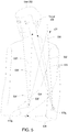
- Figure 5 illustrates a speaker included in the beamforming speaker array system of Figure 1A emitting soundwaves at different positions, according to various embodiments of the present disclosure.
- speaker 410g initially produces acoustic field 531, defined by edges 534, 536 that encompasses target 204.
- speaker 410g produces acoustic field 531 from a different position, defined by edges 534', 536'.
- speaker 410g emits a soundwave with physical characteristics specified by a received speaker signal.
- the soundwave produces acoustic field 531, which includes center axis 532 and edges 534, 536. Outside of edges 534, 536 the soundwave produced by speaker 410g may not be audible.
- spatial computation application 116 determines whether the directional sound component 539 is included within acoustic field 531. When spatial computation application 116 determines that the directional sound component is included within acoustic field 531, spatial computation application 116 may generate one or more sound parameters. The speaker signal generated from the one or more sound parameters causes speaker 410g to emit acoustic field 531.
- spatial computation application 116 may determine whether the directional sound component 539' is included within the updated acoustic field 531' and, if so, spatial computation application 116 may generate an updated speaker signal.
- the updated speaker signal may cause speaker 410g to produce directional sound component 539' that has updated center axis 532' and updated edges 534', 536'.
- spatial computation application 116 may determine that no updates to the speaker signal are necessary because target 204 remains within the area encompassed by acoustic field 531'. In such instances, spatial computation application 116 may not generate an updated speaker signal. Instead, spatial computation application 116 may transmit an unmodified speaker signal to speaker 410g, which produces acoustic field 531' at the new position.
- Figure 6 illustrates a predictive estimation of a position of a speaker included in the beamforming speaker array system of Figure 1A as a user moves, according to various embodiments of the present disclosure.
- speaker 410f changes positions to new position 410f' due to a movement 606 performed by user 202.
- user 202 may perform movement 606 as a repetitive motion during a routine, such as when running.
- Spatial computation application 116 may perform one or more predictive estimation to estimate the future position 410f' of speaker 410f based on movement 606.
- spatial computation application 116 may analyze one or more previous positions of speaker 410f to estimate one or more future positons 410f' of speaker 410f. For example, user 202 may perform a movement 606 of swinging an upper arm while keeping the shoulder fixed. In such instances, spatial computation application 116 may model the movement of speaker 410g as a sinusoidal, simple harmonic arm movement. In some embodiments, spatial computation application 116 may determine a specified distance 604 between speaker 410g and a point on the shoulder of user 202. Spatial computation application 116 may also determine an angle formed by specified distance 604 relative to axis 602 of the user's shoulder.
- Spatial computation 116 incorporates the specified distance and the modeled harmonic movement in order to predict the future location 410f' before movement 606 causes speaker 410f to reach the future location 410f.
- spatial computation application 116 may generate one or more sound parameters, audio source signals, and/or speaker signals for speaker 410f based on the predicted future location 410f' of speaker 410f. In such instances, spatial computation application 116 may send the speaker signals to speaker 410f before reaching the new position 410f'. In such instances, speaker 410f emits soundwaves based on the predicted position 410f', resulting in beamforming speaker array system 150 responding faster to a change in position.
- Figures 7A-7B illustrate a different technique to estimate the position of an individual speaker included in the beamforming speaker array system of Figure 1B , according to various embodiments of the present disclosure
- Figure 7A illustrates wearable device form factor 400, including speakers 410a-g of speaker array 130.
- spatial computation application 116 may produce sensor data and determine the positions of speakers 410a-g.
- spatial computation application 116 may simplify the determination of the positions of speakers 410a-g by determining a low-resolution position of speakers 410. For example, spatial computation application 116 may only determine the quadrant of the environment in which the speakers 410a-g are located.
- spatial computation application 116 may determine that speakers 410c-d are located in quadrant 702a ("quadrant A”), speaker 410e is located in quadrant 702b ("quadrant B"), speakers 410f-g are located in quadrant 702c (“quadrant C”), and speakers 410a-b are located in quadrant 702d (“quadrant D"). Spatial computation application 116 may compute the directional sound components for speakers 410a-g based on the quadrant in which the speaker is located.
- Figure 7B illustrates wearable device form factor 400, including sensors 402a-b, 404a-d of sensor(s) 120.
- spatial computation application 116 may acquire low-resolution sensor data that indicates one or more quadrants in which the sensor is located.
- the quadrants used for the low-resolution sensor data may be different from the quadrants used for the low-resolution positions of speakers 410a-g.
- sensors 402a-b, 404a-d acquire low-resolution sensor data indicating that sensors 404c-d are located in quadrant 704a ("quadrant 1"), sensors 404a-b are located in quadrant 704b ("quadrant 2"), sensor 402a is located in quadrant 704c ("quadrant 3"), and sensor 402b is located in quadrant 702d ("quadrant 4").
- Spatial computation application 116 may determine the configuration of speaker array 130 by based on the low-resolution sensor data acquired by sensors 402a-b, 404a-d.
- low-resolution sensor data and/or the low-resolution position of speakers 410a-g allows spatial computation application 116 to compute approximate directional sound components for speakers 410a-g faster than other computational methods that determine more precise positions and/or orientations of speakers 410a-g when determining the current configuration.
- spatial computation application 116 generates speaker signals from the approximate directional sound components. The speaker signals cause speakers 410a-g to produce the composite acoustic field at target 204, even though the estimated current configuration of speaker array 130 made by spatial computation application 116 is not as precise.
- Figure 8 is a flow diagram of method steps for generating speaker signals to emit directional sounds, according to various embodiments of the present disclosure. Although the method steps are described in conjunction with the systems of Figures 1-7B , persons skilled in the art will understand that any system configured to perform the method steps, in any order, falls within the scope of the present disclosure.
- Method 800 begins at step 801, where sensor(s) 120 receive position data.
- sensor(s) 120 may include one or more target sensors 402a-b that produce sensor data related to the position of a target 204.
- sensor(s) 120 include one or more sensors 404a-d that produce sensor data related to the positions and/or the orientations of speakers 410a-g included in speaker array 130.
- computing device 110 determines a configuration of speaker array 130.
- spatial computation application 116 analyzes sensor data received from sensor(s) 120 and determines a current configuration of speaker array 130 based on the sensor data.
- the configuration of speaker array 130 includes the specific configurations of each of the individual speakers 410a-g included in speaker array 130.
- two or more spatial computation applications 116 may separately and independently receive sensor data from sensor(s) 120 and determine the current configuration of speaker array 130.
- computing device 110 computes directional sound components 310, 320 to be emitted.
- spatial computation application 116 analyzes the current configuration 300 of speaker array 130 and computes a set of directional sound components 310, 320 to be emitted by individual speakers 410a-g included in speaker array 130.
- spatial computation application 116 computes the set of directional sound components based on the position(s) and/or orientation(s) of speakers 410a-g in the current configuration 300.
- computing device 110 generates speaker signal(s) based on the computed directional sound components.
- spatial computation application 116 may generate one or more sound parameters based on the set of computed directional sound components.
- the one or more sound parameters may be used to generate a speaker signal included in a set of speaker signals that computing device 110 transmits to speaker array 130.
- computing device 110 may transmit at least one speaker signal included in the set of speaker signals to each of the individual speakers included in speaker array 130.
- the set of speaker signals may incorporate different amplitudes and/or different transducer phase delays based on the computed directional sound components.
- a separate spatial computation application 116 may be executed to coordinate the operation of each individual speaker 410a-g included in speaker array 130. In such instances, each spatial computation application 116 may generate and transmit a single speaker signal for the corresponding speaker 410a-g. Speaker array 130 may emit soundwaves based on the set of speaker signals, where the soundwaves combine to produce a composite acoustic field at target 204. In some embodiments, after generating the speaker signal(s), computing device 110 may return to step 801 to receive position data, instead of proceeding to step 809. In such embodiments, computing device may optionally repeat steps 801-807 while computing device is playing the audio signal.
- computing device 110 may determine whether the configuration of speaker array 130 has changed.
- spatial computation application 116 may determine whether the position(s) and/or orientation(s) of one or more individual speakers included in speaker array 130 has changed after the spatial computation application 116 determined the current configuration of speaker array 130.
- the sensor(s) 120 receive additional position data before spatial computation application 116 makes the determination. If spatial computation application 116 determines that the configuration of speaker array 130 has changed, computing device 110 returns to step 803. Otherwise, if spatial computation application 116 determines that the configuration of speaker array 130 has not changed, computing device 110 ends method 800 at step 811.
- one or more sensors included in a beamforming speaker array system produce sensor data that is associated with a target location and/or with other speaker(s) included in the speaker array.
- a spatial computation application included in the beamforming speaker array system dynamically determines a current configuration of the speaker array based on the sensor data.
- the current configuration of the speaker array may include the position and/or orientation of each individual speaker included in the speaker array.
- the spatial computation application computes directional sound components of soundwaves to be emitted by the speaker array based on positions and/or orientations of the individual speakers included in the determined configuration of the speaker array.
- the spatial computation application then generates a set of speaker signals for the speaker array based on the directional sound components.
- the spatial computation application transmits one of the speaker signals in the set of speaker signals to each speaker included in the speaker array.
- separate spatial computation applications each of which is coupled to an individual speaker included in the speaker array, generate a speaker signal for the individual speakers and transmit the corresponding speaker signal to the individual speaker.
- Each speaker included in the speaker array emits a soundwave based on the speaker signal received from the set of speaker signals.
- the emitted soundwave produces an acoustic field that includes the directional sound component specified in a one or more sound parameters used to generate the speaker signal.
- the soundwaves emitted from each of the speakers may be highly directional and constructively and/or destructively combine with other acoustic fields produced from the other speakers included in the speaker array to form a composite acoustic field.
- the soundwaves included in the composite acoustic field cause the user of the beamforming speaker array system to hear audio content corresponding to the audio source signal.
- the spatial computation application continually updates the determined current configuration of the speaker array based on the changing position(s) and/or orientations of one or more individual speakers included in the speaker array.
- the spatial computation application generates updated speaker signals and transmits the updated speaker signals to the speakers so that the speakers produce a constant composite acoustic field surrounding the user's ears.
- At least one advantage of the disclosed techniques is that audio signals can be transmitted to a user's ears without requiring mechanical headphones that obstruct other audio signals from the surrounding environment.
- the beamforming speaker array continually generates new parameterized signals based on the relative positions of each of the individual speakers, the speaker array does not require a rigid spatial relationship to produce a consistent acoustic field.
- aspects of the present embodiments may be embodied as a system, method or computer program product. Accordingly, aspects of the present disclosure may take the form of an entirely hardware embodiment, an entirely software embodiment (including firmware, resident software, micro-code, etc.) or an embodiment combining software and hardware aspects that may all generally be referred to herein as a "module” or “system.” In addition, any hardware and/or software technique, process, function, component, engine, module, or system described in the present disclosure may be implemented as a circuit or set of circuits. Furthermore, aspects of the present disclosure may take the form of a computer program product embodied in one or more computer readable medium(s) having computer readable program code embodied thereon.
- the computer readable medium may be a computer readable signal medium or a computer readable storage medium.
- a computer readable storage medium may be, for example, but not limited to, an electronic, magnetic, optical, electromagnetic, infrared, or semiconductor system, apparatus, or device, or any suitable combination of the foregoing.
- a computer readable storage medium may be any tangible medium that can contain, or store a program for use by or in connection with an instruction execution system, apparatus, or device.
- each block in the flowchart or block diagrams may represent a module, segment, or portion of code, which comprises one or more executable instructions for implementing the specified logical function(s).
- the functions noted in the block may occur out of the order noted in the figures. For example, two blocks shown in succession may, in fact, be executed substantially concurrently, or the blocks may sometimes be executed in the reverse order, depending upon the functionality involved.
Abstract
Description
- Embodiments of the present disclosure relate generally to audio systems and, more specifically, to a wearable beamforming speaker array.
- Consumer electronics devices, such as smartphones, media players, tablet computers, personal computers, virtual reality (VR) devices, and/or augmented reality (AR) devices, enable users to enjoy media content in various environments and while performing a variety of different activities. Such devices commonly have an audio output device that includes one or more audio transducers. The audio transducers emit soundwaves reproducing an audio signal that represents the audio portion of the media content. When the soundwave reaches the ears of the user, the user is able to hear the audio portion of the media content.
- In some devices, the audio transducers output sound into the surrounding environment, such that the sound can be heard by others proximate to the user. Alternatively, if the user wishes to listen to the audio portion of the media content more privately and/or does not want to disturb others in the surrounding environment, then the user may listen to the audio portion via a pair of headphones, where the audio transducers output sound towards the user's ears without outputting sound into the environment.
- Although headphones generally allow a user to listen to high-quality audio content privately and/or without disturbing others, such devices have several downsides. For example, when headphones are worn by a user, the headphones may occlude the user's ears, preventing the user from hearing other sounds in the environment. In addition, headphones may move out of position while a user is moving, preventing the user from hearing the audio content and/or requiring the user to repeatedly reposition the headphones. For example, while a user is exercising or performing other activities that involve movement, on-ear or over-the-ear headphones may move relative to the head of the user, and in-ear headphones may fall out of the user's ear canal.
- As the foregoing illustrates, improved techniques for outputting audio content to a user would be useful.
- Embodiments of the present disclosure set forth an audio system including a speaker array including two or more speakers, one or more sensors configured to produce sensor data, and a processor coupled to the one or more sensors and the speaker array. The processor is configured to determine, based on the sensor data, for each speaker included in the speaker array, a position of the speaker relative to at least one of a target location, and one or more other speakers included in the speaker array, determine, based on the positions of the speakers included in the speaker array, a first set of directional sound components. Each directional sound component included in the first set of directional sound components is defined between a corresponding speaker and the target location. The processor is further configured to generate a first set of speaker signals for the speaker array based on the first set of directional sound components, where, when outputted by the speaker array, the first set of speaker signals produces an acoustic field at the target location.
- Further embodiments provide, among other things, a method and computer-readable storage medium for implementing aspects of the methods set forth above.
- At least one advantage of the disclosed techniques is that an audio portion of media content can be provided to a user without requiring the user to wear headphones that obstruct other sounds in the surrounding environment from reaching the user. In addition, a composite acoustic field can be generated in a variety of different spatial configurations, despite changes to the position(s) and/or orientation(s) of individual speakers included in the speaker array. This adaptability of the beamforming speaker array system enables greater design flexibility, allowing the system to be implemented in a variety of different form factors.
- So that the manner in which the above recited features of the various embodiments can be understood in detail, a more particular description of the inventive concepts, briefly summarized above, may be had by reference to various embodiments, some of which are illustrated in the appended drawings. It is to be noted, however, that the appended drawings illustrate only typical embodiments of the inventive concepts and are therefore not to be considered limiting of scope in any way, and that there are other equally effective embodiments.
-
Figure 1A illustrates a block diagram of a beamforming speaker array system configured to implement one or more aspects of the present disclosure. -
Figure 1B illustrates a technique for processing sensor data and audio data via the spatial computation application ofFigure 1A to output audio content, according to various embodiments of the present disclosure. -
Figure 2 illustrates the beamforming speaker array system ofFigure 1A in a wearable device form factor, according to various embodiments of the present disclosure. -
Figure 3 illustrates a configuration of the beamforming speaker array system ofFigure 1A and directional sound components emitted by the speakers towards a target, according to various embodiment of the present disclosure. -
Figure 4 illustrates the beamforming speaker array system ofFigure 1A in a wearable device form factor that includes position sensors, according to various embodiments of the present disclosure. -
Figure 5 illustrates a speaker included in the beamforming speaker array system ofFigure 1A emitting soundwaves at different positions, according to various embodiments of the present disclosure. -
Figure 6 illustrates a predictive estimation of a position of a speaker included in the beamforming speaker array system ofFigure 1A as a user moves, according to various embodiments of the present disclosure. -
Figures 7A-7B illustrate a different technique to estimate the position of an individual speaker included in the beamforming speaker array system ofFigure 1B , according to various embodiments of the present disclosure. -
Figure 8 is a flow diagram of method steps for generating speaker signals to emit directional sounds, according to various embodiments of the present disclosure. - In the following description, numerous specific details are set forth to provide a more thorough understanding of the various embodiments. However, it will be apparent to one of skilled in the art that the inventive concepts may be practiced without one or more of these specific details.
-
Figure 1A illustrates a block diagram of a beamformingspeaker array system 100 configured to implement one or more aspects of the present disclosure. Beamformingspeaker array system 100 includescomputing device 110, one ormore sensors 120, andspeaker array 130.Computing device 110 includesprocessing unit 112 andmemory 114.Memory 114 storesspatial computation application 116 anddatabase 118. - In operation,
processing unit 112 receives sensor data from sensor(s) 120.Processing unit 112 executesspatial computation application 116 to analyze the sensor data and determine the current configuration ofspeaker array 130, including the positions and/or orientations of the individual speakers included inspeaker array 130. Upon determining the current configuration ofspeaker array 130,spatial computation application 116 determines directional sound components from which speaker signals are to be emitted by each speaker included in thespeaker array 130. The speaker signals produce a particular acoustic field at a target location, such as proximate to the ears of a user. - Once the
spatial computation application 116 determines directional sound components,spatial computation application 116 may then generate one or more sound parameters for each speaker in thespeaker array 130.Spatial computation application 116 then generates one or more speaker signals based on the one or more sound parameters and based on an audio source signal. The speaker signals may then be transmitted to the speakers included in thespeaker array 130, which receive the speaker signals and output sound based on the speaker signals. The sound outputted by the speakers (e.g., a speaker and an amplifier) included inspeaker array 130 then combines to produce a composite acoustic field at the target location. In some embodiments, the target location includes the ears of a user, enabling the user to listen to a high-quality, composite acoustic field via multiple speakers that are located proximate to the user. - In some embodiments, the one or more sound parameters may include, without limitation, a direction in which a target is located relative to a speaker (e.g., relative to a center axis of a speaker), a sound level to be outputted by a speaker in order to generate a desired sound level at a target location (e.g., a target location that is off-axis relative to a speaker), a distance between a speaker and a target location, a distance and/or angle between the speaker and one or more other speakers included in the
speaker array 130, a phase delay to be applied to a speaker signal in order to generate a desired acoustic field at a target location, etc. For example, thespatial computation application 116 could determine one or more sound parameters that include an angular direction of a target location relative to a center axis of the speaker. Thespatial computation application 116 could then determine, based on the one or more sound parameters, a sound level that should be outputted by the speaker in order to generate a desired sound level at the target location. - Sensor(s) 120 include one or more devices that detect positions of objects in an environment by performing measurements and/or collecting data. In some embodiments, the one or
more sensors 120 may be coupled to and/or included within individual speakers included inspeaker array 130. In such instances,computing device 110 may receive sensor data via the one ormore sensors 120, where the sensor data reflects the position(s) and/or orientation(s) of one or more speakers included inspeaker array 130. The position(s) and/or orientation(s) of the one or more speakers may be derived from the absolute position of the one ormore sensors 120, or may be derived from a relative position of an object to the one ormore sensors 120.Processing unit 112 then executesspatial computation application 116 to analyze the received sensor data to determine a current configuration ofspeaker array 130, including the position(s) and/or the orientation(s) of the one or more speakers. - In some embodiments, sensor(s) 120 may produce sensor data that is associated with the positions of portions of the user's body. For example, sensor(s) 120 may be positioned near one or more ears of the user and may produce sensor data.
Processing unit 112 may analyze the sensor data to track the location of one of the user's ears, both of the user's ears, and/or the user's head based on the sensor data. Thespatial computation application 116 may then determine a target location at which an acoustic field will be generated based on the location(s). - In various embodiments, the one or
sensors 120 may include position sensors, such as an accelerometer or an inertial measurement unit (IMU). The IMU may be a device like a three-axis accelerometer, gyroscopic sensor, and/or magnetometer. In some embodiments, sensor(s) 120 may include optical sensors, such RGB cameras, time-of-flight sensors, infrared (IR) cameras, depth cameras, and/or a quick response (QR) code tracking system. In addition, in some embodiments, sensor(s) 120 may include wireless sensors, including radio frequency (RF) sensors (e.g., sonar and radar), ultrasound-based sensors, capacitive sensors, laser-based sensors, and/or wireless communications protocols, including Bluetooth, Bluetooth low energy (BLE), wireless local area network (WiFi) cellular protocols, and/or near-field communications (NFC). - As noted above,
computing device 110 may include processingunit 112 andmemory 114.Computing device 110 may be a device that includes one ormore processing units 112, such as a system-on-a-chip (SoC), or a mobile computing device, such as a tablet computer, mobile phone, media player, and so forth. In some embodiments,computing device 110 is integrated with an individual speaker included inspeaker array 130. Generally,computing device 110 may be configured to coordinate the overall operation of beamformingspeaker array system 100. In some embodiments,computing device 110 may be coupled to, but be separate from, one or more individual speakers included inspeaker array 130. In such instances,computing device 110 may be included in a separate device. The embodiments disclosed herein contemplate any technically-feasible system configured to implement the functionality of beamformingspeaker array system 100 viacomputing device 110. -
Processing unit 112 may include a central processing unit (CPU), a digital signal processing unit (DSP), a microprocessor, an application-specific integrated circuit (ASIC), a neural processing unit (NPU), a graphics processing unit (GPU), a field-programmable gate array (FPGA), and so forth. In some embodiments, processingunit 112 may be configured to executespatial computation application 116 in order to analyze sensor data acquired by sensor(s) 120 and determine a current configuration ofspeaker array 130. In some embodiments, processingunit 112 may be configured to executespatial computation application 116 to compute one or more directional sound components, where the one or more directional sound components are based on the determined current configuration ofspeaker array 130.Processing unit 112 is configured to executespatial computation application 116 to generate one or more sound parameters based on the directional sound components. The one or more sound parameters include one or more parameters that cause thespeaker array 130 to emit soundwaves based on the sound parameters. In some embodiments, processingunit 112 is configured to generate speaker signals from the one or more sound parameters and then transmit the speaker signals tospeaker array 130. In some embodiments, processingunit 112 transmits the speaker signals to one or more speakers inspeaker array 130 wirelessly. - In various embodiments, processing
unit 112 executesspatial computation application 116 in order to determine sound parameters and generate speaker signals for all speakers included in thespeaker array 130. Alternatively, in some embodiments, each speaker included inspeaker array 130 may include a separate processing unit that determines one or more sound parameters for that speaker and/or generates a speaker signal to be outputted by that speaker, based on the one or more sound parameters. In such instances, each speaker may include a processing unit that executes an instance of thespatial computation application 116 in order to generate a single speaker signal for a single speaker. In some embodiments, eachspatial computation application 116 may also determine the current configuration of thespeaker array 130 and determine one or more sound parameters for that speaker based on the configuration of thespeaker array 130. - Additionally, in some embodiments, processing
unit 112 could executespatial computation application 116 to determine one or more sound parameters for each speaker. The sound parameter(s) could then be transmitted to each speaker, and a processing unit included in each speaker could generate and output a speaker signal based on the sound parameter(s). Accordingly, although various embodiments disclosed herein are described as being performed via aprocessing unit 112 that executesspatial computation application 116, each of the disclosed techniques could be performed by separate processing units included in individual speakers. -
Memory 114 may include a memory module or collection of memory modules.Spatial computation application 116 withinmemory 114 may be executed by processingunit 112 to implement the overall functionality of thecomputing device 110 and, thus, to coordinate the operation of the beamformingspeaker array system 100 as a whole. -
Database 118 may store values and other data retrieved by processingunit 112 to coordinate the operation of beamformingspeaker array system 100. During operation, processingunit 112 may be configured to store values indatabase 118 and/or retrieve values stored indatabase 118. For example,database 118 may store sensor data, predictive estimation values, audio content, digital signal processing algorithms, transducer parameter data, and so forth. - During operation, the configuration of
speaker array 130 may change. The change in the updated configuration ofspeaker array 130 may be due to a change in position(s) and/or orientation(s) of one or more individual speakers. In such instances,speaker array 130 may receive updated sound parameters generated byspatial computation application 116, where the updated sound parameters account for the updated configuration.Speaker array 130 may then emit soundwaves based on the updated sound parameters in order to continue to produce a composite acoustic field at the target location. Accordingly,speaker array 130 may be configured to consistently produce the composite acoustic field at the target location, even as the configuration ofspeaker array 130 changes. -
Figure 1B illustrates a technique for processing sensor data and audio data via thespatial computation application 116 ofFigure 1A to output audio content, according to various embodiments of the present disclosure. In some embodiments of block diagram 150, one or more speakers included inspeaker array 130 includes aprocessing unit 135. In various embodiments, processingunit 135 may include one or more digital signal processors (DSPs). In other embodiments, none of the individual speakers included inspeaker array 130 include aprocessing unit 135. In such instances, processingunit 112 included incomputing device 100 may execute one or more digital signal processing algorithms that would otherwise be performed by processingunit 135. - During operation, sensor(s) 120 transmit sensor data to
spatial computation application 116.Spatial computation application 116 analyzes the sensor data to determine the current configuration ofspeaker array 130. In various embodiments, the current configuration ofspeaker array 130 includes the position(s) and/or orientation(s) of individual speakers. In various embodiments, the position(s) and/or orientation(s) may be based on absolute positions within an environment. In other embodiments, the position(s) and/or orientation(s) may be relative to the other individual speakers included inspeaker array 130. For example, the current configuration ofspeaker array 130 includes the position(s) and/or orientation(s) of individual speakers relative to a target location and/or relative to one or more other devices (e.g., the ears of the user,computing device 110,audio source 120, and so forth). Upon determining the current configuration ofspeaker array 130,spatial computation application 116 computes a set of directional sound components that are to be part of acoustic fields produced by a set of soundwaves to be emitted byspeaker array 130. -
Audio source 160 generates one or more audio source signals to be delivered to at least one ofspatial computation application 116 and/orspeaker array 130. In general,audio source 160 may include any type of audio device, such as a personal media player, a smartphone, a portable computer, a television, etc. In some embodiments,spatial computation application 116 receives one or more audio source signals directly fromaudio source 160. In such instances,spatial computation application 116 may process the audio source signal(s) to generate the sound parameters and/or speakers signals that are to be transmitted to the speakers included inspeaker array 130. In some embodiments,spatial computation application 116 may generate sound parameters based on the locations and/or orientations of the speakers relative to each other and/or relative to a target location. The sound parameters may then be transmitted to the corresponding speakers. The digital signal processing unit (DSP) 135 included in each speaker may separately process the audio source signal received fromaudio source 160, and then generate and output a speaker signal based on the corresponding sound parameter(s) and the audio source signal in order to generate a desired acoustic field at the target location. - In some embodiments,
spatial computation application 116 may modify the frequency characteristics associated with the sound outputted by one or more speakers. In various embodiments,spatial computation application 116 may select the subset of individual speakers to produce the modified speaker signals based on an intended audio effect (e.g., surround sound, bass boost, and so forth). For example,spatial computation application 116 could cause only a subset of individual speakers, such as a subset of speakers included inspeaker array 130 closest to the target location, to emit soundwaves that correspond to high-frequency portions of the audio source signal. In such instances,spatial computation application 116 may filter an audio source signal included in the one or more speaker signals in order to isolate and/or remove low-frequency audio content.Speaker array 130 may then produce a composite acoustic field that has the filtered audio source signal. - For example, when modifying the speaker signal to emphasize the high-frequency portions,
spatial computation application 116 can first generate a subset of speaker signals from the high-frequency portions of the audio source signal.Spatial computation application 116 can then transmit this subset of speaker signals to a specified subset of individual speakers included inspeaker array 130. In another example,spatial computation application 116 may compensate for phase delays between individual speakers due to the current configuration ofspeaker array 130. In such instances,spatial computation application 116 may determine sound parameters that include a phase delay between individual speakers.Spatial computation application 116 may then generate modified speaker signals that compensate for individual soundwaves emitted by different individual speakers reaching the target location at different times. -
Figure 2 illustrates the beamformingspeaker array system 150 ofFigure 1A in a wearabledevice form factor 200, according to various embodiments of the present disclosure. Wearabledevice form factor 200 is worn by a user 202 with atarget 204 being located proximate to the user's head. In some embodiments,target 204 may include the user's ears 206a-b.Wearable form factor 200 includesspeaker array 130, which has multipleindividual speakers 210a-f attached to the body of user 202 in different positions. -
Speakers 210a-f are individual speakers included inspeaker array 130.Speakers 210a-f may be loudspeakers that include one or more audio transducers that are configured to emit soundwaves based at least on one or more speaker signals received fromspatial computation application 116. As the plurality of soundwaves fromspeakers 210a-f propagate towardstarget 204, the acoustic fields produced by soundwaves interfere with each other constructively and destructively to combine and produce a composite acoustic field. - In some embodiments, each
speaker 210a-f may receive a separate speaker signal that includes a different modified audio source signal from a set of modified audio source signals. Each of the different modified audio source signals may incorporate different characteristics associated with the audio source signal, such as a specified frequency. Each ofspeakers 210a-f may be configured to reproduce one of the different modified audio source signals by emitting a soundwave based on a received speaker signal that includes the modified audio source signal. - In some embodiments, one or more of
speakers 210a-f included inspeaker array 130 may be positioned on the body of user 202 through an attachment device, or attached to clothing (e.g., a jacket, shirt, sweatshirt, etc.) that user 202 wears. For example,speakers 210a-f may be sewn into the arms of the clothing of user 202, be attached via adhesive, and/or be mechanically attached via an attachment mechanism. In some embodiments, one or more ofspeakers 210a-f include sensor(s) 120 that produce sensor data. -
Spatial computation application 116 analyzes sensor data to determine the current configuration ofspeaker array 130, including the position(s) and/or orientation(s) for eachspeaker 210a-f. The current configuration ofspeaker array 130 includes a specific configuration of eachspeaker 210a-f. In some embodiments, the specific configuration of anindividual speaker 210a includes one or more of an absolute position of theindividual speaker 210a within the environment, a position ofindividual speaker 210a to relative otherindividual speakers 210b-f, and/or a position ofindividual speaker 210a torelative target 204 and/or other devices likecomputing device 110 and/oraudio source 160. In some embodiments, the specific configuration of anindividual speaker 210a includes an absolute angular orientation of one or more audio transducers included inindividual speaker 210a based on one or more axes within the environment, and/or an angular orientation of the one or more audio transducers relative to another location or device within the environment, such astarget 204. -
Speaker array 130 is configured to emit soundwaves from at least one or more ofspeakers 210a-f in order to produce a composite acoustic field attarget 204. In some embodiments, eachspeaker 210a-f included inspeaker array 130 emits a separate soundwave. Each of the soundwaves generates a specific acoustic field, where the acoustic fields interfere with each other constructively and destructively to produce a composite acoustic field.Speaker array 130 may be configured to produce a composite acoustic field that is large enough to encompass all oftarget 204. - In some embodiments,
speaker array 130 continues to produce a composite acoustic field proximate to target 204, even as the configuration ofspeaker array 130 changes from the current configuration to a different configuration. For example, the current configuration ofspeaker array 130 may change due to one or more ofspeakers 210a-f changing position(s) and/or orientation(s). The change in position(s) and/or orientation(s) may be due, for example, to a movement made by user 202. In some embodiments,speaker array 130 may be configured to produce multiple composite acoustic fields simultaneously, where a first set ofspeakers 210a-c included inspeaker array 130 produces a first composite acoustic field that encompasses ear 206a, and a second set ofspeakers 210d-f included inspeaker array 130 produces a second composite acoustic field that encompassesear 206b. -
Figure 3 illustrates aconfiguration 300 of the beamformingspeaker array system 100 ofFigure 1A anddirectional sound components speakers 210a-f towards atarget 204, according to various embodiments of the present disclosure.Configuration 300 illustrates the positions ofspeakers 210a-f ofspeaker array 130 within a three-dimensional space of the environment that includestarget 204. In some embodiments, one ormore speakers 210a-f may be configured emit soundwaves towardstarget 204. -
Spatial computation application 116 analyzes sensor data received from sensor(s) 120 and determinesconfiguration 300 ofspeakers 210a-f. In some embodiments,spatial computation application 116 determines specific configurations forindividual speakers 210a-f included inconfiguration 300, as well as spatial relationships between one or moreindividual speakers 210a-f andother speakers 210a-f,computing device 110, sensor(s) 120,audio source 160, and/ortarget 204. - In some embodiments, the specific configuration of an
individual speaker 210d includes information associated with the absolute position and/or absolute orientation of theindividual speaker 210d within the environment. For example,spatial computation application 116 may determine the absolute position ofspeaker 210d within the environment and store the absolute position as a set of {x, y, z} coordinates. Similarly,spatial computation application 116 may determine the absolute orientation of an audio transducer included in speaker and store the absolute orientation as a set of angles {θ0, ϕ0, ψ0} relative to the x-axis, y-axis, and z-axis specified within the environment, respectively. In various embodiments, the specific configuration of anindividual speaker 210d includes information associated with the position(s) of theindividual speaker 210d relative to other devices and/or locations within the environment. For example,spatial computation application 116 may determine the position ofspeaker 210d as a set of scalar and/or vector distances relative to target 204, relative to otherindividual speakers 210a-c, 210e-f, relative to sensor(s) 120, relative toaudio source 160, and/or relative tocomputing device 110. - Based on the
configuration 300,spatial computation application 116 computes one or moredirectional sound components more speakers 210a-f included inspeaker array 130. In some embodiments, multiplespatial computation applications 116 may compute one or moredirectional sound components configuration 300. In such instances, eachspatial computation application 116 may separately determineconfiguration 300 and separately determine at least one directional sound component. - During operation,
spatial computation application 116 computes a directional sound component as a component of an acoustic field produced by aspeaker 210a-f emitting a soundwave. The directional sound component includes one or more physical characteristics. The physical characteristics of the directional sound component define how a portion of a soundwave emitted from anindividual speaker 210d propagates within the environment. In some embodiments, the characteristics of the directional sound component may be components of a vector, such as an amplitude and/or set of angles. -
Spatial computation application 116 computes the directional sound components of one or more speakers based on one or more sound parameters of the acoustic field that is to be produced. When computing the directional sound components,spatial computation application 116 determines sound parameters associated with the sound that is to be emitted byspeakers 210a-f. In such instances,spatial computation application 116 may execute at least one algorithm to compute the directional sound components that are to be produced byspeakers 210a-f that optimize at least one parameter of the resultant acoustic field. - In some embodiments,
spatial computation application 116 may control the intensity (as measured by pressure and volume velocity) of each directional sound component in order to control the parameters of the acoustic field. Similarly,spatial computation 116 may also control one or more phase delays between each directional sound component in order to control or optimize the resultant acoustic field. - For example, when optimizing the parameters of the acoustic field,
spatial computation application 116 computes the sound parameters of the acoustic field such that the acoustic field includes a "bright zone" of high sound pressure, where the bright zone enables the user to hear the audio signal. In some embodiments,spatial computation application 116 optimizes the bright zone by computing the acoustic potential energy, which determines the magnitude of a sound perception. Optimizing the acoustic potential energy enablesspeaker array 130 to produce the largest magnitude of sound perception for a given input energy. - For example,
spatial computation application 116 could determine the pressure levels of the acoustic field that is to be produced by performing a pressure mapping of the environment based on the soundwaves thatspeakers 210a-f are to emit.Spatial computation application 116 could then determine an acoustic potential energy, which determines the magnitude of a sound perception, by computing the pressure of a specific area within the environment (e.g., the bright zone) based on the positions ofspeakers 210a-f and thedirectional sound components - In another example,
spatial computation application 116 could determine an acoustic potential energy as a difference in energy relative to the environment. For example,spatial computation application 116 could controlspeakers 210a-f in order for the target acoustic field to have an energy difference ("acoustic contrast") of at least 10 dB compared to the surrounding environment. In such instances,spatial computation application 116 could implement an acoustic contrast control (ACC) to cause the one or more directional sound components to produce an acoustic field that has a bright zone, with such a difference in acoustic potential energy relative to the environment. In some embodiments,spatial computation application 116 may compute directional sound components in order forspeaker array 130 to emit soundwaves that produce an acoustic field that has characteristics corresponding to the acoustic contrast. - In some embodiments,
spatial computation application 116 may compute the planarity of the acoustic field, which measures the extent to which the acoustic field within the bright zone resembles a plane wave. The planarity of the acoustic field may be computed based on the angle and energy levels of each soundwave upon reaching the bright zone.Spatial computation application 116 may optimize the energy included in the bright zone by optimizing the planarity of the acoustic field. -
Spatial computation application 116 computes at least one directional sound component inspeaker array 130. For example,spatial computation application 116 computes adirectional sound component 310 forspeaker 210d, which includes an amplitude corresponding to the intensity of the soundwave and multiple absolute angles relative to defined axes within the environment, such as first angle 312 (θ) relative to the x-axis, second angle 314 (ϕ) relative to the y-axis, and third angle 316 (ψ) relative to the z-axis. In another example,spatial computation application 116 computes adirectional sound 320 forspeaker 210f that has defined characteristics, including an amplitude, first angle 322 (θ), second angle 324 (ϕ), and third angle 326 (ψ). - In another example,
spatial computation application 116 computesdirectional sound component 330 relative to centeraxis 332 ofacoustic field 331 produced byspeaker 210c.Spatial computation application 116 computes an inclination angle (β) 339 ofdirectional sound component 330 relative to centeraxis 332.Spatial computation application 116 also computes coverage angle (α) 338 corresponding to the angle relative to thecenter axis 332, where the soundwave produced byspeaker 210c is audible. In some embodiments,spatial computation application 116 may compareinclination angle 339 withcoverage angle 338 to determine whetherspeaker 210c producesdirectional sound component 330 by emitting the soundwave that producesacoustic field 331. Whenspeaker 210c would not producedirectional sound component 330,spatial computation application 116 may generate one or more sound parameters that causesspeaker 210c not to emit a soundwave. -
Spatial computation application 116 generates speaker signals that causespeakers 210a-f to emit soundwaves that include the computeddirectional sound components spatial computation application 116 generates one or more sound parameters forspeaker 210d corresponding todirectional sound component speaker 210a-f receives a speaker signal that is generated from the one or more sound parameters,speaker 210a-f emits a soundwave that produces an acoustic field includes at leastdirectional sound component - In some embodiments, when
speaker 210a-f cannot produce an acoustic field that includesdirectional sound component spatial computation application 116 may generate a speaker signal that preventsspeaker 210a-f from emitting a soundwave. For example, when the audio transducer ofspeaker 210a-f has an orientation that is opposite to the characteristic angles {θ, ϕ, ψ, α, β} 312, 314, 316, 338, 339 ofdirectional sound components spatial computation application 116 may generate sounds parameter(s) and/or speaker signal that causesspeaker 210a-f to not emit a soundwave. - In some embodiments,
speaker 210f may be configured to emit a soundwave with a higher intensity (in pressure and/or velocity) than a soundwave emitted byspeaker Speaker 210f may emit a soundwave with a higher intensity becausespeaker 210f is positioned further away fromtarget 204 thanspeaker directional sound component 320 may have a higher intensity than directionalsound components - In some embodiments,
speakers speaker 210f reachestarget 204 at a later time than the soundwave emitted byspeakers spatial computation application 116 may compensate for the delay of the soundwave emitted byspeaker 210f reaching target 204. For example,spatial computation application 116 may incorporate a transducer phase delay into the one or more sound parameters for one or more ofspeakers 210a-f. In various embodiments,spatial computation application 116 may incorporate the transducer phase delay the speaker signal generated from the one or more sound parameters and transmit the speaker signal to a specifiedspeaker 210d. The specifiedspeaker 210d may then emit a soundwave that includes the transducer phase delay. In other embodiments,spatial computation application 116 may delay transmission of one of the speaker signals for a time specified by the transducer phase delay. Because one ormore speakers 210a-f incorporate the transducer phase delay,speakers 210a-f emit soundwaves that reachtarget 204 simultaneously or a within a threshold time period. -
Figure 4 illustrates the beamforming speaker array system ofFigure 1A in a wearable device form factor that includes position sensors, according to various embodiments of the present disclosure.Wearable form factor 200 includes a user 202 wearing clothing, wherespeaker array 130, including multipleindividual speakers 410a-g, is attached to user 202 and/or attached to the clothing of user 202.Multiple position sensors 120, includingtarget sensors 402a-b andsensors 404a-d, are also attached to user 202 and/or attached to the clothing of user 202. - In some embodiments,
sensors 120 includemultiple sensors 402a-b, 404a-d. In various embodiments, one ormore sensors 402a-b, 404a-d included in thesensors 120 may be associated with a specific device and/or a specific location. For example, each oftarget sensors 402a-b may be associated with a specific target location (e.g., an ear of user 202). In such instances,target sensors 402a-b may produce sensor data for a location within the environment.Spatial computation application 116 may analyze the produced sensor data and, by applying the known relationship betweentarget sensors 402a-b and the associated target location, may track the target location based on the produced sensor data. For example,spatial computation application 116 may storespecific distance 406a betweentarget sensor 402a and the ear of user 202 as a known relationship.Spatial computation application 116 may storespecific distance 406b betweentarget sensor 402b and the other ear of user 202 as a different known relationship.Spatial computation application 116 similarly stores a knowndistance 412 betweensensor 410g andsensor 404d.Spatial computation application 116 may analyze the produced sensor data fromtarget sensor 402a and may then applyspecific distance 406a to the analyzed sensor data in order to estimate the position of the ear of user 202. - In some embodiments, one or more of
sensors 404a-d may produce sensor data at specific locations on the body of the user.Spatial computation application 116 may analyze the produced sensor data and apply known relationships betweenindividual sensors 404a-d and/or known relationships betweenindividual sensors 404a-d andindividual speakers 410a-g in order to determine the current configuration ofspeaker array 130. For example,sensors sensor 404b is attached to the elbow, andsensor 404c is attached to the upper arm of user 202.Spatial computation application 116 may analyze the produced sensor data to determine the positon of eachsensor 404a-d. After determining the position of eachsensor 404a-d,spatial computation application 116 may apply known relationships betweensensors 404a-d andspeakers 410a-g, such asdistance 412, and determine the configuration ofspeaker array 130. In some embodiments,spatial computation application 116 may incorporate a known skeletal model of the user to determine the position of user 202 and/orspeakers 410a-g positioned on the body of the user based on the produced sensor data. -
Speaker array 130 includesspeakers 410a-g attached to user 202 at various locations of the body of the user. For example,speakers 410a-c are attached to one arm of the user,speakers 410e-f are attached to another arm of the user, andspeaker 410d is attached to the chest of the user. In some embodiments,spatial computation application 116 may determine one or more distances between asensor 404a-d and one ormore speakers 410a-g and store the one or more distances as known relationship(s).Spatial computation application 116 may determine the current configuration ofspeakers 410a-g based on the produced sensor data and the known relationship(s) betweensensors 404a-d andspeakers 410a-g. -
Figure 5 illustrates a speaker included in the beamforming speaker array system ofFigure 1A emitting soundwaves at different positions, according to various embodiments of the present disclosure. As illustrated,speaker 410g initially producesacoustic field 531, defined byedges target 204. When user 202 performsmovement 506,speaker 410g producesacoustic field 531 from a different position, defined by edges 534', 536'. - In some embodiments,
speaker 410g emits a soundwave with physical characteristics specified by a received speaker signal. The soundwave producesacoustic field 531, which includescenter axis 532 andedges edges speaker 410g may not be audible. In some embodiments,spatial computation application 116 determines whether thedirectional sound component 539 is included withinacoustic field 531. Whenspatial computation application 116 determines that the directional sound component is included withinacoustic field 531,spatial computation application 116 may generate one or more sound parameters. The speaker signal generated from the one or more sound parameters causesspeaker 410g to emitacoustic field 531. - When user 202 performs
arm movement 506,speaker 410g is in a new position and/or orientation relative to target 204. In some embodiments,spatial computation application 116 may determine whether the directional sound component 539' is included within the updated acoustic field 531' and, if so,spatial computation application 116 may generate an updated speaker signal. The updated speaker signal may causespeaker 410g to produce directional sound component 539' that has updated center axis 532' and updated edges 534', 536'. In some embodiments,spatial computation application 116 may determine that no updates to the speaker signal are necessary becausetarget 204 remains within the area encompassed by acoustic field 531'. In such instances,spatial computation application 116 may not generate an updated speaker signal. Instead,spatial computation application 116 may transmit an unmodified speaker signal tospeaker 410g, which produces acoustic field 531' at the new position. -
Figure 6 illustrates a predictive estimation of a position of a speaker included in the beamforming speaker array system ofFigure 1A as a user moves, according to various embodiments of the present disclosure. As illustrated,speaker 410f changes positions tonew position 410f' due to amovement 606 performed by user 202. For example, user 202 may performmovement 606 as a repetitive motion during a routine, such as when running.Spatial computation application 116 may perform one or more predictive estimation to estimate thefuture position 410f' ofspeaker 410f based onmovement 606. - In some embodiments,
spatial computation application 116 may analyze one or more previous positions ofspeaker 410f to estimate one or morefuture positons 410f' ofspeaker 410f. For example, user 202 may perform amovement 606 of swinging an upper arm while keeping the shoulder fixed. In such instances,spatial computation application 116 may model the movement ofspeaker 410g as a sinusoidal, simple harmonic arm movement. In some embodiments,spatial computation application 116 may determine a specifieddistance 604 betweenspeaker 410g and a point on the shoulder of user 202.Spatial computation application 116 may also determine an angle formed by specifieddistance 604 relative toaxis 602 of the user's shoulder. -
Spatial computation 116 incorporates the specified distance and the modeled harmonic movement in order to predict thefuture location 410f' beforemovement 606 causesspeaker 410f to reach thefuture location 410f. In various embodiments,spatial computation application 116 may generate one or more sound parameters, audio source signals, and/or speaker signals forspeaker 410f based on the predictedfuture location 410f' ofspeaker 410f. In such instances,spatial computation application 116 may send the speaker signals tospeaker 410f before reaching thenew position 410f'. In such instances,speaker 410f emits soundwaves based on the predictedposition 410f', resulting in beamformingspeaker array system 150 responding faster to a change in position. -
Figures 7A-7B illustrate a different technique to estimate the position of an individual speaker included in the beamforming speaker array system ofFigure 1B , according to various embodiments of the present disclosureFigure 7A illustrates wearabledevice form factor 400, includingspeakers 410a-g ofspeaker array 130. In some embodiments,spatial computation application 116 may produce sensor data and determine the positions ofspeakers 410a-g. In lieu of determining a precise position and/or orientation ofspeakers 410a-g,spatial computation application 116 may simplify the determination of the positions ofspeakers 410a-g by determining a low-resolution position of speakers 410. For example,spatial computation application 116 may only determine the quadrant of the environment in which thespeakers 410a-g are located. - For example,
spatial computation application 116 may determine thatspeakers 410c-d are located inquadrant 702a ("quadrant A"),speaker 410e is located inquadrant 702b ("quadrant B"),speakers 410f-g are located inquadrant 702c ("quadrant C"), andspeakers 410a-b are located inquadrant 702d ("quadrant D").Spatial computation application 116 may compute the directional sound components forspeakers 410a-g based on the quadrant in which the speaker is located. -
Figure 7B illustrates wearabledevice form factor 400, includingsensors 402a-b, 404a-d of sensor(s) 120. In some embodiments,spatial computation application 116 may acquire low-resolution sensor data that indicates one or more quadrants in which the sensor is located. The quadrants used for the low-resolution sensor data may be different from the quadrants used for the low-resolution positions ofspeakers 410a-g. For example,sensors 402a-b, 404a-d acquire low-resolution sensor data indicating thatsensors 404c-d are located inquadrant 704a ("quadrant 1"),sensors 404a-b are located inquadrant 704b ("quadrant 2"),sensor 402a is located inquadrant 704c ("quadrant 3"), andsensor 402b is located inquadrant 702d ("quadrant 4").Spatial computation application 116 may determine the configuration ofspeaker array 130 by based on the low-resolution sensor data acquired bysensors 402a-b, 404a-d. - In some embodiments, low-resolution sensor data and/or the low-resolution position of
speakers 410a-g allowsspatial computation application 116 to compute approximate directional sound components forspeakers 410a-g faster than other computational methods that determine more precise positions and/or orientations ofspeakers 410a-g when determining the current configuration. In some embodiments,spatial computation application 116 generates speaker signals from the approximate directional sound components. The speaker signals causespeakers 410a-g to produce the composite acoustic field attarget 204, even though the estimated current configuration ofspeaker array 130 made byspatial computation application 116 is not as precise. -
Figure 8 is a flow diagram of method steps for generating speaker signals to emit directional sounds, according to various embodiments of the present disclosure. Although the method steps are described in conjunction with the systems ofFigures 1-7B , persons skilled in the art will understand that any system configured to perform the method steps, in any order, falls within the scope of the present disclosure. -
Method 800 begins atstep 801, where sensor(s) 120 receive position data. In some embodiments, sensor(s) 120 may include one ormore target sensors 402a-b that produce sensor data related to the position of atarget 204. In some embodiments, sensor(s) 120 include one ormore sensors 404a-d that produce sensor data related to the positions and/or the orientations ofspeakers 410a-g included inspeaker array 130. - At
step 803,computing device 110 determines a configuration ofspeaker array 130. In some embodiments,spatial computation application 116 analyzes sensor data received from sensor(s) 120 and determines a current configuration ofspeaker array 130 based on the sensor data. The configuration ofspeaker array 130 includes the specific configurations of each of theindividual speakers 410a-g included inspeaker array 130. In some embodiments, two or morespatial computation applications 116 may separately and independently receive sensor data from sensor(s) 120 and determine the current configuration ofspeaker array 130. - At
step 805,computing device 110 computesdirectional sound components spatial computation application 116 analyzes thecurrent configuration 300 ofspeaker array 130 and computes a set ofdirectional sound components individual speakers 410a-g included inspeaker array 130. In some embodiments,spatial computation application 116 computes the set of directional sound components based on the position(s) and/or orientation(s) ofspeakers 410a-g in thecurrent configuration 300. - At
step 807,computing device 110 generates speaker signal(s) based on the computed directional sound components. In some embodiments,spatial computation application 116 may generate one or more sound parameters based on the set of computed directional sound components. The one or more sound parameters may be used to generate a speaker signal included in a set of speaker signals thatcomputing device 110 transmits tospeaker array 130. In such instances,computing device 110 may transmit at least one speaker signal included in the set of speaker signals to each of the individual speakers included inspeaker array 130. The set of speaker signals may incorporate different amplitudes and/or different transducer phase delays based on the computed directional sound components. - In some embodiments, a separate
spatial computation application 116 may be executed to coordinate the operation of eachindividual speaker 410a-g included inspeaker array 130. In such instances, eachspatial computation application 116 may generate and transmit a single speaker signal for thecorresponding speaker 410a-g.Speaker array 130 may emit soundwaves based on the set of speaker signals, where the soundwaves combine to produce a composite acoustic field attarget 204. In some embodiments, after generating the speaker signal(s),computing device 110 may return to step 801 to receive position data, instead of proceeding to step 809. In such embodiments, computing device may optionally repeat steps 801-807 while computing device is playing the audio signal. - At
step 809,computing device 110 may determine whether the configuration ofspeaker array 130 has changed. In some embodiments,spatial computation application 116 may determine whether the position(s) and/or orientation(s) of one or more individual speakers included inspeaker array 130 has changed after thespatial computation application 116 determined the current configuration ofspeaker array 130. In some embodiments, the sensor(s) 120 receive additional position data beforespatial computation application 116 makes the determination. Ifspatial computation application 116 determines that the configuration ofspeaker array 130 has changed,computing device 110 returns to step 803. Otherwise, ifspatial computation application 116 determines that the configuration ofspeaker array 130 has not changed,computing device 110 endsmethod 800 atstep 811. - In sum, one or more sensors included in a beamforming speaker array system produce sensor data that is associated with a target location and/or with other speaker(s) included in the speaker array. A spatial computation application included in the beamforming speaker array system dynamically determines a current configuration of the speaker array based on the sensor data. The current configuration of the speaker array may include the position and/or orientation of each individual speaker included in the speaker array. The spatial computation application computes directional sound components of soundwaves to be emitted by the speaker array based on positions and/or orientations of the individual speakers included in the determined configuration of the speaker array. The spatial computation application then generates a set of speaker signals for the speaker array based on the directional sound components. The spatial computation application transmits one of the speaker signals in the set of speaker signals to each speaker included in the speaker array. In some embodiments, separate spatial computation applications, each of which is coupled to an individual speaker included in the speaker array, generate a speaker signal for the individual speakers and transmit the corresponding speaker signal to the individual speaker.
- Each speaker included in the speaker array emits a soundwave based on the speaker signal received from the set of speaker signals. The emitted soundwave produces an acoustic field that includes the directional sound component specified in a one or more sound parameters used to generate the speaker signal. The soundwaves emitted from each of the speakers may be highly directional and constructively and/or destructively combine with other acoustic fields produced from the other speakers included in the speaker array to form a composite acoustic field. The soundwaves included in the composite acoustic field cause the user of the beamforming speaker array system to hear audio content corresponding to the audio source signal. In various embodiments, the spatial computation application continually updates the determined current configuration of the speaker array based on the changing position(s) and/or orientations of one or more individual speakers included in the speaker array. The spatial computation application generates updated speaker signals and transmits the updated speaker signals to the speakers so that the speakers produce a constant composite acoustic field surrounding the user's ears.
- At least one advantage of the disclosed techniques is that audio signals can be transmitted to a user's ears without requiring mechanical headphones that obstruct other audio signals from the surrounding environment. In addition, because the beamforming speaker array continually generates new parameterized signals based on the relative positions of each of the individual speakers, the speaker array does not require a rigid spatial relationship to produce a consistent acoustic field.
- Any and all combinations of any of the claim elements recited in any of the claims and/or any elements described in this application, in any fashion, fall within the contemplated scope of the present disclosure and protection.
- The descriptions of the various embodiments have been presented for purposes of illustration, but are not intended to be exhaustive or limited to the embodiments disclosed. Many modifications and variations will be apparent to those of ordinary skill in the art without departing from the scope and spirit of the described embodiments.
- Aspects of the present embodiments may be embodied as a system, method or computer program product. Accordingly, aspects of the present disclosure may take the form of an entirely hardware embodiment, an entirely software embodiment (including firmware, resident software, micro-code, etc.) or an embodiment combining software and hardware aspects that may all generally be referred to herein as a "module" or "system." In addition, any hardware and/or software technique, process, function, component, engine, module, or system described in the present disclosure may be implemented as a circuit or set of circuits. Furthermore, aspects of the present disclosure may take the form of a computer program product embodied in one or more computer readable medium(s) having computer readable program code embodied thereon.
- Any combination of one or more computer readable medium(s) may be utilized. The computer readable medium may be a computer readable signal medium or a computer readable storage medium. A computer readable storage medium may be, for example, but not limited to, an electronic, magnetic, optical, electromagnetic, infrared, or semiconductor system, apparatus, or device, or any suitable combination of the foregoing. More specific examples (a non-exhaustive list) of the computer readable storage medium would include the following: an electrical connection having one or more wires, a portable computer diskette, a hard disk, a random access memory (RAM), a read-only memory (ROM), an erasable programmable read-only memory (EPROM or Flash memory), an optical fiber, a portable compact disc read-only memory (CD-ROM), an optical storage device, a magnetic storage device, or any suitable combination of the foregoing. In the context of this document, a computer readable storage medium may be any tangible medium that can contain, or store a program for use by or in connection with an instruction execution system, apparatus, or device.
- Aspects of the present disclosure are described above with reference to flowchart illustrations and/or block diagrams of methods, apparatus (systems) and computer program products according to embodiments of the disclosure. It will be understood that each block of the flowchart illustrations and/or block diagrams, and combinations of blocks in the flowchart illustrations and/or block diagrams, can be implemented by computer program instructions. These computer program instructions may be provided to a processor of a general purpose computer, special purpose computer, or other programmable data processing apparatus to produce a machine. The instructions, when executed via the processor of the computer or other programmable data processing apparatus, enable the implementation of the functions/acts specified in the flowchart and/or block diagram block or blocks. Such processors may be, without limitation, general purpose processors, special-purpose processors, application-specific processors, or field-programmable gate arrays.
- The flowchart and block diagrams in the figures illustrate the architecture, functionality, and operation of possible implementations of systems, methods and computer program products according to various embodiments of the present disclosure. In this regard, each block in the flowchart or block diagrams may represent a module, segment, or portion of code, which comprises one or more executable instructions for implementing the specified logical function(s). It should also be noted that, in some alternative implementations, the functions noted in the block may occur out of the order noted in the figures. For example, two blocks shown in succession may, in fact, be executed substantially concurrently, or the blocks may sometimes be executed in the reverse order, depending upon the functionality involved. It will also be noted that each block of the block diagrams and/or flowchart illustration, and combinations of blocks in the block diagrams and/or flowchart illustration, can be implemented by special purpose hardware-based systems that perform the specified functions or acts, or combinations of special purpose hardware and computer instructions.
- While the preceding is directed to embodiments of the present disclosure, other and further embodiments of the disclosure may be devised without departing from the basic scope thereof, and the scope thereof is determined by the claims that follow.
Claims (15)
- An audio system, comprising:a speaker array comprising two or more speakers;one or more sensors configured to produce sensor data; anda processor coupled to the one or more sensors and the speaker array and configured to:determine, based on the sensor data, for each speaker included in the speaker array, a position of the speaker relative to at least one of a target location and one or more other speakers included in the speaker array,determine, based on the positions of the speakers included in the speaker array, a first set of directional sound components, wherein each directional sound component included in the first set of directional sound components is defined between a corresponding speaker and the target location, andgenerate a first set of speaker signals for the speaker array based on the first set of directional sound components, wherein, when outputted by the speaker array, the first set of speaker signals produces an acoustic field at the target location.
- The system of claim 1, wherein the one or more sensors includes a plurality of sensors, wherein each sensor included in the plurality of sensors detects at least one of:a location of a different speaker included in the speaker array; andan orientation of a different speaker included in the speaker array.
- The system of claim 1, wherein the processor is further configured to:receive, from an audio source, an audio source signal to be outputted via the speaker array,wherein generating the first set of speaker signals comprises modifying, based on the first set of directional sound components, at least one of:a phase of the audio source signal, andan intensity of the audio source signal.
- The system of claim 3, wherein modifying the at least one of the phase and the intensity of the audio source signal comprises modifying a first phase of at least a portion of the audio source signal based on a distance between a first speaker included in the speaker array and the target location.
- The system of claim 3, wherein modifying the at least one of the phase and the intensity of the audio source signal comprises modifying a first intensity of at least a portion of the audio source signal based on an orientation of a center axis of a first speaker included in the speaker array relative to the target location.
- The system of claim 1, wherein the processor is further configured to:determine, based on additional sensor data, for each speaker included in the speaker array, a second position of the speaker,determine, based on the second positions of the speakers, a second set of directional sound components, wherein each directional sound component included in the second set of directional sound components is defined between the corresponding speaker and the target location, andgenerate a second set of speaker signals for the speaker array based on the second set of directional sound components, wherein, when outputted by the speaker array, the second set of speaker signals produces a second acoustic field at the target location.
- The system of claim 6, wherein the processor is configured to determine the second positions of the speakers based at least on a predictive estimation of a first speaker included in the speaker array.
- The system of claim 7, wherein the predictive estimation of the first speaker is based at least on a model of a skeleton of the user.
- The system of claim 1, wherein the one or more sensors includes a target sensor, and wherein the processor is further configured to determine the target location based on the sensor data acquired from the target sensor.
- The system of claim 9, wherein a first speaker of the speaker array generates a first acoustic field based on a first speaker signal included in the first set of speaker signals, a second speaker of the speaker array generates a second acoustic field based on a second speaker signal included in the first set of speaker signals, and the first acoustic field constructively combines with the second acoustic field to produce a composite acoustic field at the target location.
- A computer-implemented method, comprising:determining, based on sensor data acquired from one or more sensors, for each speaker included in a speaker array, a first position of the speaker relative to a target location;determining, based on at least the first position of a first speaker included in the speaker array, a first speaker directional sound component defined between the first speaker and the target location, andgenerating, for the first speaker, a first speaker signal based on the first speaker directional sound component, wherein, when outputted by the first speaker, the first speaker signal produces a portion of an acoustic field at the target location.
- The computer-implemented method of claim 11, further comprising:determining, based on at least the first position of a second speaker in the speaker array, a second speaker directional sound component defined between the second speaker and the target location; andgenerating, for the second speaker, a second speaker signal based on the second speaker directional sound component, wherein, when outputted by the second speaker, the second speaker produces a second portion of the acoustic field at the target location.
- The computer-implemented method of claim 11, further comprising:determining, based on additional sensor data, for each speaker included in the speaker array, a second position of the speaker relative to the target location;determining, based on at least the second position of the first speaker, an updated first speaker directional sound component defined between the first speaker and the target location, andgenerating, for the first speaker, an updated first speaker signal based on the updated first speaker directional sound component, wherein, when outputted by the first speaker, the updated first speaker signal produces a portion of an updated acoustic field at the target location.
- The computer-implemented method of claim 11, further comprising:receiving, from an audio source, an audio source signal to be outputted via the speaker array,wherein generating the first speaker signal comprises modifying, based on the first speaker directional sound component, at least one of:a phase of the audio source signal, andan intensity of the audio source signal.
- A non-transitory computer-readable medium for storing program instructions that, when executed by a processor, causes the processor to perform the steps of:determining, based on sensor data acquired from one or more sensors, a position for each speaker included in a speaker array, wherein the position of the speaker is relative to at least one of a target location and one or more other speakers included in the speaker array;determining, based on the positions of the speakers included in the speaker array, a first set of directional sound components, wherein each directional sound component included in the first set of directional sound components is defined between a corresponding speaker and the target location; andgenerating a first set of speaker signals for the speaker array based on the first set of directional sound components, wherein a first speaker signal included in the first set of speaker signals is generated based on a difference between (i) a first distance between a first speaker included in the speaker array and the target location and (ii) a second distance between a second speaker included in the speaker array and the target location.
Applications Claiming Priority (1)
| Application Number | Priority Date | Filing Date | Title |
|---|---|---|---|
| US16/203,537 US20200169809A1 (en) | 2018-11-28 | 2018-11-28 | Wearable beamforming speaker array |
Publications (2)
| Publication Number | Publication Date |
|---|---|
| EP3661233A1 true EP3661233A1 (en) | 2020-06-03 |
| EP3661233B1 EP3661233B1 (en) | 2023-12-27 |
Family
ID=68653330
Family Applications (1)
| Application Number | Title | Priority Date | Filing Date |
|---|---|---|---|
| EP19210571.6A Active EP3661233B1 (en) | 2018-11-28 | 2019-11-21 | Wearable beamforming speaker array |
Country Status (3)
| Country | Link |
|---|---|
| US (1) | US20200169809A1 (en) |
| EP (1) | EP3661233B1 (en) |
| CN (1) | CN111246341A (en) |
Families Citing this family (1)
| Publication number | Priority date | Publication date | Assignee | Title |
|---|---|---|---|---|
| CN117354680A (en) * | 2023-11-08 | 2024-01-05 | 北京逸和软件科技有限公司 | Sound orientation method, system and terminal based on digital sounding chip |
Citations (3)
| Publication number | Priority date | Publication date | Assignee | Title |
|---|---|---|---|---|
| US20140270321A1 (en) * | 2013-03-13 | 2014-09-18 | Aliphcom | Non-occluded personal audio and communication system |
| WO2016054090A1 (en) * | 2014-09-30 | 2016-04-07 | Nunntawi Dynamics Llc | Method to determine loudspeaker change of placement |
| WO2017003472A1 (en) * | 2015-06-30 | 2017-01-05 | Harman International Industries, Incorporated | Shoulder-mounted robotic speakers |
Family Cites Families (11)
| Publication number | Priority date | Publication date | Assignee | Title |
|---|---|---|---|---|
| US4825471A (en) * | 1987-06-29 | 1989-05-02 | Oliver Jennings | Garment useful for listening to audio signals |
| CN101194536B (en) * | 2005-06-09 | 2012-11-14 | 皇家飞利浦电子股份有限公司 | Method of and system for determining distances between loudspeakers |
| US8737634B2 (en) * | 2011-03-18 | 2014-05-27 | The United States Of America As Represented By The Secretary Of The Navy | Wide area noise cancellation system and method |
| GB2508830B (en) * | 2012-12-11 | 2017-06-21 | Holition Ltd | Augmented reality system and method |
| KR20140099122A (en) * | 2013-02-01 | 2014-08-11 | 삼성전자주식회사 | Electronic device, position detecting device, system and method for setting of speakers |
| US10219094B2 (en) * | 2013-07-30 | 2019-02-26 | Thomas Alan Donaldson | Acoustic detection of audio sources to facilitate reproduction of spatial audio spaces |
| US20150189455A1 (en) * | 2013-12-30 | 2015-07-02 | Aliphcom | Transformation of multiple sound fields to generate a transformed reproduced sound field including modified reproductions of the multiple sound fields |
| US9712940B2 (en) * | 2014-12-15 | 2017-07-18 | Intel Corporation | Automatic audio adjustment balance |
| DK179070B1 (en) * | 2015-12-11 | 2017-10-02 | Bang & Olufsen As | Sound radiating entity |
| US20170188170A1 (en) * | 2015-12-29 | 2017-06-29 | Koninklijke Kpn N.V. | Automated Audio Roaming |
| US10271132B2 (en) * | 2016-11-28 | 2019-04-23 | Motorola Solutions, Inc. | Method to dynamically change the directional speakers audio beam and level based on the end user activity |
-
2018
- 2018-11-28 US US16/203,537 patent/US20200169809A1/en not_active Abandoned
-
2019
- 2019-11-21 EP EP19210571.6A patent/EP3661233B1/en active Active
- 2019-11-28 CN CN201911188617.XA patent/CN111246341A/en active Pending
Patent Citations (3)
| Publication number | Priority date | Publication date | Assignee | Title |
|---|---|---|---|---|
| US20140270321A1 (en) * | 2013-03-13 | 2014-09-18 | Aliphcom | Non-occluded personal audio and communication system |
| WO2016054090A1 (en) * | 2014-09-30 | 2016-04-07 | Nunntawi Dynamics Llc | Method to determine loudspeaker change of placement |
| WO2017003472A1 (en) * | 2015-06-30 | 2017-01-05 | Harman International Industries, Incorporated | Shoulder-mounted robotic speakers |
Also Published As
| Publication number | Publication date |
|---|---|
| CN111246341A (en) | 2020-06-05 |
| EP3661233B1 (en) | 2023-12-27 |
| US20200169809A1 (en) | 2020-05-28 |
Similar Documents
| Publication | Publication Date | Title |
|---|---|---|
| US10863270B1 (en) | Beamforming for a wearable computer | |
| JP7229925B2 (en) | Gain control in spatial audio systems | |
| CN107211216B (en) | For providing the method and apparatus of virtual audio reproduction | |
| US9622013B2 (en) | Directional sound modification | |
| US10257637B2 (en) | Shoulder-mounted robotic speakers | |
| US11812235B2 (en) | Distributed audio capture and mixing controlling | |
| CN105263075B (en) | A kind of band aspect sensor earphone and its 3D sound field restoring method | |
| US11009954B2 (en) | Haptics device for producing directional sound and haptic sensations | |
| US10542368B2 (en) | Audio content modification for playback audio | |
| JPWO2018060549A5 (en) | ||
| EP3661233B1 (en) | Wearable beamforming speaker array | |
| WO2022061342A2 (en) | Methods and systems for determining position and orientation of a device using acoustic beacons | |
| US10667073B1 (en) | Audio navigation to a point of interest | |
| KR20120005464A (en) | Apparatus and method for the binaural reproduction of audio sonar signals | |
| CN115988381A (en) | Directional sound production method, device and equipment | |
| US20210210114A1 (en) | Wearable device including a sound detection device providing location information for a body part | |
| JP6194740B2 (en) | Audio processing apparatus, audio processing method, and program | |
| US20240122781A1 (en) | Information processing device, information processing method, and program | |
| US11114082B1 (en) | Noise cancelation to minimize sound exiting area | |
| WO2022172648A1 (en) | Information processing device, information processing method, and program | |
| US20240073571A1 (en) | Generating microphone arrays from user devices | |
| Hu et al. | HeadTrack: Real-time Human-Computer Interaction via Wireless Earphones | |
| WO2023122282A1 (en) | Determination of movement direction | |
| CN117376804A (en) | Motion detection of speaker unit | |
| JP2018074437A (en) | Signal processing device, signal processing system, signal processing method, and program |
Legal Events
| Date | Code | Title | Description |
|---|---|---|---|
| PUAI | Public reference made under article 153(3) epc to a published international application that has entered the european phase |
Free format text: ORIGINAL CODE: 0009012 |
|
| STAA | Information on the status of an ep patent application or granted ep patent |
Free format text: STATUS: THE APPLICATION HAS BEEN PUBLISHED |
|
| AK | Designated contracting states |
Kind code of ref document: A1 Designated state(s): AL AT BE BG CH CY CZ DE DK EE ES FI FR GB GR HR HU IE IS IT LI LT LU LV MC MK MT NL NO PL PT RO RS SE SI SK SM TR |
|
| AX | Request for extension of the european patent |
Extension state: BA ME |
|
| STAA | Information on the status of an ep patent application or granted ep patent |
Free format text: STATUS: REQUEST FOR EXAMINATION WAS MADE |
|
| 17P | Request for examination filed |
Effective date: 20201201 |
|
| RBV | Designated contracting states (corrected) |
Designated state(s): AL AT BE BG CH CY CZ DE DK EE ES FI FR GB GR HR HU IE IS IT LI LT LU LV MC MK MT NL NO PL PT RO RS SE SI SK SM TR |
|
| STAA | Information on the status of an ep patent application or granted ep patent |
Free format text: STATUS: EXAMINATION IS IN PROGRESS |
|
| 17Q | First examination report despatched |
Effective date: 20210806 |
|
| REG | Reference to a national code |
Ref country code: DE Ref legal event code: R079 Ref document number: 602019043945 Country of ref document: DE Free format text: PREVIOUS MAIN CLASS: H04S0007000000 Ipc: H04R0001400000 Ref country code: DE Ipc: H04R0001400000 |
|
| GRAP | Despatch of communication of intention to grant a patent |
Free format text: ORIGINAL CODE: EPIDOSNIGR1 |
|
| STAA | Information on the status of an ep patent application or granted ep patent |
Free format text: STATUS: GRANT OF PATENT IS INTENDED |
|
| RIC1 | Information provided on ipc code assigned before grant |
Ipc: H04S 7/00 20060101ALI20230531BHEP Ipc: H04R 3/12 20060101ALI20230531BHEP Ipc: H04R 1/40 20060101AFI20230531BHEP |
|
| INTG | Intention to grant announced |
Effective date: 20230619 |
|
| GRAS | Grant fee paid |
Free format text: ORIGINAL CODE: EPIDOSNIGR3 |
|
| GRAA | (expected) grant |
Free format text: ORIGINAL CODE: 0009210 |
|
| STAA | Information on the status of an ep patent application or granted ep patent |
Free format text: STATUS: THE PATENT HAS BEEN GRANTED |
|
| P01 | Opt-out of the competence of the unified patent court (upc) registered |
Effective date: 20231019 |
|
| AK | Designated contracting states |
Kind code of ref document: B1 Designated state(s): AL AT BE BG CH CY CZ DE DK EE ES FI FR GB GR HR HU IE IS IT LI LT LU LV MC MK MT NL NO PL PT RO RS SE SI SK SM TR |
|
| REG | Reference to a national code |
Ref country code: GB Ref legal event code: FG4D |
|
| REG | Reference to a national code |
Ref country code: CH Ref legal event code: EP |
|
| REG | Reference to a national code |
Ref country code: DE Ref legal event code: R096 Ref document number: 602019043945 Country of ref document: DE |
|
| REG | Reference to a national code |
Ref country code: IE Ref legal event code: FG4D |
|
| PG25 | Lapsed in a contracting state [announced via postgrant information from national office to epo] |
Ref country code: GR Free format text: LAPSE BECAUSE OF FAILURE TO SUBMIT A TRANSLATION OF THE DESCRIPTION OR TO PAY THE FEE WITHIN THE PRESCRIBED TIME-LIMIT Effective date: 20240328 |
|
| REG | Reference to a national code |
Ref country code: LT Ref legal event code: MG9D |