EP3661197B1 - Display control device, display control system, display control method, and display control program - Google Patents
Display control device, display control system, display control method, and display control program Download PDFInfo
- Publication number
- EP3661197B1 EP3661197B1 EP18839068.6A EP18839068A EP3661197B1 EP 3661197 B1 EP3661197 B1 EP 3661197B1 EP 18839068 A EP18839068 A EP 18839068A EP 3661197 B1 EP3661197 B1 EP 3661197B1
- Authority
- EP
- European Patent Office
- Prior art keywords
- vehicle
- line
- display control
- center
- parking
- Prior art date
- Legal status (The legal status is an assumption and is not a legal conclusion. Google has not performed a legal analysis and makes no representation as to the accuracy of the status listed.)
- Active
Links
Images






Classifications
-
- G—PHYSICS
- G06—COMPUTING OR CALCULATING; COUNTING
- G06V—IMAGE OR VIDEO RECOGNITION OR UNDERSTANDING
- G06V20/00—Scenes; Scene-specific elements
- G06V20/50—Context or environment of the image
- G06V20/56—Context or environment of the image exterior to a vehicle by using sensors mounted on the vehicle
- G06V20/58—Recognition of moving objects or obstacles, e.g. vehicles or pedestrians; Recognition of traffic objects, e.g. traffic signs, traffic lights or roads
- G06V20/586—Recognition of moving objects or obstacles, e.g. vehicles or pedestrians; Recognition of traffic objects, e.g. traffic signs, traffic lights or roads of parking space
-
- H—ELECTRICITY
- H04—ELECTRIC COMMUNICATION TECHNIQUE
- H04N—PICTORIAL COMMUNICATION, e.g. TELEVISION
- H04N7/00—Television systems
- H04N7/18—Closed-circuit television [CCTV] systems, i.e. systems in which the video signal is not broadcast
- H04N7/183—Closed-circuit television [CCTV] systems, i.e. systems in which the video signal is not broadcast for receiving images from a single remote source
-
- B—PERFORMING OPERATIONS; TRANSPORTING
- B60—VEHICLES IN GENERAL
- B60R—VEHICLES, VEHICLE FITTINGS, OR VEHICLE PARTS, NOT OTHERWISE PROVIDED FOR
- B60R1/00—Optical viewing arrangements; Real-time viewing arrangements for drivers or passengers using optical image capturing systems, e.g. cameras or video systems specially adapted for use in or on vehicles
- B60R1/02—Rear-view mirror arrangements
-
- B—PERFORMING OPERATIONS; TRANSPORTING
- B60—VEHICLES IN GENERAL
- B60R—VEHICLES, VEHICLE FITTINGS, OR VEHICLE PARTS, NOT OTHERWISE PROVIDED FOR
- B60R1/00—Optical viewing arrangements; Real-time viewing arrangements for drivers or passengers using optical image capturing systems, e.g. cameras or video systems specially adapted for use in or on vehicles
- B60R1/20—Real-time viewing arrangements for drivers or passengers using optical image capturing systems, e.g. cameras or video systems specially adapted for use in or on vehicles
- B60R1/22—Real-time viewing arrangements for drivers or passengers using optical image capturing systems, e.g. cameras or video systems specially adapted for use in or on vehicles for viewing an area outside the vehicle, e.g. the exterior of the vehicle
- B60R1/23—Real-time viewing arrangements for drivers or passengers using optical image capturing systems, e.g. cameras or video systems specially adapted for use in or on vehicles for viewing an area outside the vehicle, e.g. the exterior of the vehicle with a predetermined field of view
- B60R1/24—Real-time viewing arrangements for drivers or passengers using optical image capturing systems, e.g. cameras or video systems specially adapted for use in or on vehicles for viewing an area outside the vehicle, e.g. the exterior of the vehicle with a predetermined field of view in front of the vehicle
-
- B—PERFORMING OPERATIONS; TRANSPORTING
- B60—VEHICLES IN GENERAL
- B60R—VEHICLES, VEHICLE FITTINGS, OR VEHICLE PARTS, NOT OTHERWISE PROVIDED FOR
- B60R1/00—Optical viewing arrangements; Real-time viewing arrangements for drivers or passengers using optical image capturing systems, e.g. cameras or video systems specially adapted for use in or on vehicles
- B60R1/20—Real-time viewing arrangements for drivers or passengers using optical image capturing systems, e.g. cameras or video systems specially adapted for use in or on vehicles
- B60R1/22—Real-time viewing arrangements for drivers or passengers using optical image capturing systems, e.g. cameras or video systems specially adapted for use in or on vehicles for viewing an area outside the vehicle, e.g. the exterior of the vehicle
- B60R1/23—Real-time viewing arrangements for drivers or passengers using optical image capturing systems, e.g. cameras or video systems specially adapted for use in or on vehicles for viewing an area outside the vehicle, e.g. the exterior of the vehicle with a predetermined field of view
- B60R1/26—Real-time viewing arrangements for drivers or passengers using optical image capturing systems, e.g. cameras or video systems specially adapted for use in or on vehicles for viewing an area outside the vehicle, e.g. the exterior of the vehicle with a predetermined field of view to the rear of the vehicle
-
- B—PERFORMING OPERATIONS; TRANSPORTING
- B60—VEHICLES IN GENERAL
- B60R—VEHICLES, VEHICLE FITTINGS, OR VEHICLE PARTS, NOT OTHERWISE PROVIDED FOR
- B60R21/00—Arrangements or fittings on vehicles for protecting or preventing injuries to occupants or pedestrians in case of accidents or other traffic risks
-
- B—PERFORMING OPERATIONS; TRANSPORTING
- B62—LAND VEHICLES FOR TRAVELLING OTHERWISE THAN ON RAILS
- B62D—MOTOR VEHICLES; TRAILERS
- B62D15/00—Steering not otherwise provided for
- B62D15/02—Steering position indicators ; Steering position determination; Steering aids
- B62D15/027—Parking aids, e.g. instruction means
- B62D15/0275—Parking aids, e.g. instruction means by overlaying a vehicle path based on present steering angle over an image without processing that image
-
- G—PHYSICS
- G06—COMPUTING OR CALCULATING; COUNTING
- G06T—IMAGE DATA PROCESSING OR GENERATION, IN GENERAL
- G06T7/00—Image analysis
-
- H—ELECTRICITY
- H04—ELECTRIC COMMUNICATION TECHNIQUE
- H04N—PICTORIAL COMMUNICATION, e.g. TELEVISION
- H04N7/00—Television systems
- H04N7/18—Closed-circuit television [CCTV] systems, i.e. systems in which the video signal is not broadcast
-
- B—PERFORMING OPERATIONS; TRANSPORTING
- B60—VEHICLES IN GENERAL
- B60R—VEHICLES, VEHICLE FITTINGS, OR VEHICLE PARTS, NOT OTHERWISE PROVIDED FOR
- B60R2300/00—Details of viewing arrangements using cameras and displays, specially adapted for use in a vehicle
- B60R2300/80—Details of viewing arrangements using cameras and displays, specially adapted for use in a vehicle characterised by the intended use of the viewing arrangement
- B60R2300/806—Details of viewing arrangements using cameras and displays, specially adapted for use in a vehicle characterised by the intended use of the viewing arrangement for aiding parking
-
- B—PERFORMING OPERATIONS; TRANSPORTING
- B62—LAND VEHICLES FOR TRAVELLING OTHERWISE THAN ON RAILS
- B62D—MOTOR VEHICLES; TRAILERS
- B62D15/00—Steering not otherwise provided for
- B62D15/02—Steering position indicators ; Steering position determination; Steering aids
- B62D15/027—Parking aids, e.g. instruction means
Definitions
- the present invention relates to a display control device, a display control system, a display control method, and a display control program.
- a technique that, when a vehicle is moving backward, superimposes a guide line indicating a predicted path of backward motion on a rearward video image captured using a rear camera mounted at the back of the vehicle and displays this video image on a display unit such as a monitor to easily and accurately guide the vehicle to a parking space has become popular recently.
- the vehicle-mounted imaging device disclosed in Patent Literature 1 takes a video showing the back of a vehicle at the time of parking the vehicle, for example, and displays the video image showing the back of the vehicle on an in-vehicle monitor, and further superimposes a predicted path in the moving direction of the vehicle on this video image showing the back of the vehicle.
- US 2008/158011 A1 relates to a parking assist apparatus for assisting a parking operation of a vehicle, the apparatus including an image capturing portion, a displaying portion, a guiding portion, and a superimposing portion.
- US 2016/094807 A1 relates to an image processing apparatus, a processor of the apparatus being configured to generate a support image by superimposing a derived trace line and a derived prediction line on an acquired photographic image of a region near a host vehicle, and displaying the support image in the host vehicle.
- FIG. 14 shows an example of the related art.
- a video image 40 shown in this example is a video image captured using a rear camera mounted at the back of a vehicle, on which a guide line 70 indicating a predicted path of the vehicle's backward motion is superimposed.
- a driver is moving a vehicle 10 to a parking space 33 that includes parking lines 30 and 31.
- the guide line 70 corresponds to the width of the vehicle 10 and is drawn along an intended path of the vehicle.
- the parking line 30 and the guide line 70 overlap.
- a guide line superimposed on a rearward video image overlaps a parking line in some cases. In such cases, it is difficult for a driver to find out the parking line in the displayed video image. Thus, there are cases where it is difficult for a driver to grasp the positional relationship between a vehicle and a parking space.
- the present embodiment has been accomplished to solve the above problems and an object of the present invention is thus to provide a display control device, a display control system, a display control method, and a display control program that support intuitive vehicle handling by reducing difficulty of visually determining a parking line displayed on a display unit.
- a display control device includes a video data acquisition unit configured to acquire video data from a camera that captures a video in a moving direction of a vehicle, a parking line recognition unit configured to recognize a parking line being a line of a parking space from the video data, a center line generation unit configured to generate a center line of the parking space based on the recognized parking line, and two center limit lines having a distance from the center line corresponding to a difference along the width between the parking line and the vehicle, the difference being calculated based on the recognized parking line and the width of the vehicle registered in advance, a vehicle moving line generation unit configured to generate a vehicle moving line extending in the moving direction of the vehicle from a position corresponding to a center part along a width of the vehicle, a superimposed video generation unit configured to generate superimposed data being video data where the center line, the center limit lines and the vehicle moving line are superimposed on the video data, and a display control unit configured to transmit the superimposed data to a display unit so as to display a video related to the superimposed data
- a display control method includes acquiring video data from a camera that captures a video in a moving direction of a vehicle, recognizing a parking line being a line of a parking space from the video data, generating a center line of the parking space from the recognized parking line, and two center limit lines having a distance from the center line corresponding to a difference along the width between the parking line and the vehicle, the difference being calculated based on the recognized parking line and the width of the vehicle registered in advance, generating a vehicle moving line extending in the moving direction of the vehicle from a position corresponding to a center part along a width of the vehicle, generating superimposed data being video data where the center line, the center limit lines and the vehicle moving line are superimposed on the video data, and transmitting the superimposed data to a display unit so as to display a video related to the superimposed data on the display unit.
- a display control program causes a computer to execute acquiring video data from a camera that captures a video in a moving direction of a vehicle, recognizing a parking line being a line of a parking space from the video data, generating a center line of the parking space from the recognized parking line, and two center limit lines having a distance from the center line corresponding to a difference along the width between the parking line and the vehicle, the difference being calculated based on the recognized parking line and the width of the vehicle registered in advance, generating a vehicle moving line extending in the moving direction of the vehicle from a position corresponding to a center part along a width of the vehicle, generating superimposed data being video data where the center line, the center limit lines and the vehicle moving line are superimposed on the video data, and transmitting the superimposed data to a display unit so as to display a video related to the superimposed data on the display unit.
- a display control device a display control system, a display control method, and a display control program that support intuitive vehicle handling by reducing difficulty of visually determining a parking line displayed on a display unit.
- Fig. 1 is a functional block diagram of a display control system 100 according to the first example.
- the following description and the drawings are appropriately shortened and simplified to clarify the explanation.
- the identical reference symbols denote identical structural elements, and the redundant explanation thereof is omitted.
- the display control system 100 is a system that, when a driver is moving a vehicle to a parking space or the like, superimposes a center line of the parking space and a vehicle moving line indicating the moving direction of the vehicle on a video image captured by a camera 180 that takes a video of a vehicle moving direction and displays this video image on a display unit 190.
- the display control system 100 may be implemented as one function of a car navigation system, a dashboard camera or the like which can be retrofitted to a vehicle, for example.
- a display control device 101 may be implemented as one function of a system incorporated into a vehicle when assembling the vehicle in a factory, for example.
- the display control device 101 may be implemented by combining a system incorporated into a vehicle when assembling the vehicle in a factory and a device that can be retrofitted to a vehicle, for example.
- the display control system 100 includes the display control device 101 and at least one of the camera 180 and the display unit 190.
- the display control device 101 acquires video data, which is data of a video captured by the camera 180, superimposes a vehicle moving line on this data and displays the data on the display unit 190.
- the display control device 101 may be implemented as a device in various forms such as a computer device that operates when a processor executes a program stored in a memory.
- the processor may be a micro processor, an MPU (Micro Processing Unit), or a CPU (Central Processing Unit), for example.
- the memory is a volatile memory or a nonvolatile memory, and it may be a combination of a volatile memory and a nonvolatile memory.
- the processor executes one or a plurality of programs including a group of instructions for causing a computer to perform processing according to an example.
- the display control device 101 is connected with a CAN (Controller Area Network) or the like, which is an in-car network. Further, the display control device 101 is connected with the camera 180 and the display unit 190.
- the CAN or the like means that it may be an in-car network such as MOST (Media Oriented Systems Transport) or Ethernet (registered trademark), not limited to the CAN.
- the program can be stored and provided to the computer using any type of non-transitory computer readable medium.
- the non-transitory computer readable medium includes any type of tangible storage medium. Examples of the non-transitory computer readable medium include magnetic storage media (such as floppy disks, magnetic tapes, hard disk drives, etc.), optical magnetic storage media (e.g. magneto-optical disks), CD-ROM (Read Only Memory), CD-R , CD-R/W, and semiconductor memories (such as mask ROM, PROM (Programmable ROM), EPROM (Erasable PROM), flash ROM, RAM (Random Access Memory), etc.).
- the program may be provided to a computer using any type of transitory computer readable medium. Examples of the transitory computer readable medium include electric signals, optical signals, and electromagnetic waves.
- the transitory computer readable medium can provide the program to a computer via a wired communication line such as an electric wire or optical fiber or a wireless communication line.
- the display control device 101 includes a vehicle moving line generation unit 110, a video data acquisition unit 120, a parking line recognition unit 130, a center line generation unit 140, a superimposed video generation unit 150, and a display control unit 160.
- the vehicle moving line generation unit 110 generates a vehicle moving line that extends in the moving direction of the vehicle from a center part along the width of a vehicle.
- the vehicle moving line is line information indicating the moving direction of the vehicle by being superimposed on video data captured by the camera 180.
- An example of a method of generating the vehicle moving line in the vehicle moving line generation unit 110 is schematically described below.
- the camera 180 is placed at the center part along the width of a vehicle so as to take a video in the moving direction of the vehicle.
- the vehicle moving line generation unit 110 generates the vehicle moving line where the initial setting is such that the camera 180 is placed at the center part along the width of a vehicle so as to take a video in the moving direction of the vehicle.
- the initial setting is a setting that displays a predetermined length of line extending vertically from the center part along the width in the underside of a screen of the display unit 190.
- the display control system 100 may have the function that allows a user to adjust the position, angle, length and the like of the vehicle moving line.
- the vehicle moving line generation unit 110 transmits information about the generated vehicle moving line to the superimposed video generation unit 150.
- the video data acquisition unit 120 acquires the video data generated in the camera 180.
- the video data acquisition unit 120 acquires digital video data or analog video data from the camera 180.
- the video data acquisition unit transmits the video data to the superimposed video generation unit 150 as uncompressed digital video data or compressed video data in a format such as H.264 or H.265, for example.
- the video data acquisition unit 120 may generate video data in a compressed video format such as MPEG (Moving Picture Experts Group) 2-TS (Transport Stream) or AVI (Audio Video Interleave).
- MPEG Motion Picture Experts Group
- 2-TS Transport Stream
- AVI Audio Video Interleave
- the video data acquisition unit 120 transmits the video data to the superimposed video generation unit 150. Note that it is arbitrary in which block compression is to be performed or whether data is to be compressed or uncompressed, and compressed video data may be acquired from a camera unit, for example.
- the parking line recognition unit 130 recognizes parking lines displayed in a parking space from the video data transmitted from the video data acquisition unit 120. A specific example of a technique of recognizing parking lines in the parking line recognition unit 130 is described below.
- the parking line recognition unit 130 calculates a luminance gradient of each pixel of the video data, for example.
- the parking line recognition unit 130 then recognizes parking lines by using a predetermined technique such as edge detection.
- a technique of calculating a luminance gradient of each pixel of video data and recognizing a target object is a known technique. Thus, the detailed description thereof is omitted.
- the parking line recognition unit 130 recognizes parking lines and thereby generates information about whether parking lines exist in the video data and the positions of parking lines in the video data.
- the parking line recognition unit 130 transmits the generated information to the center line generation unit 140. Further, when the parking line recognition unit 130 does not recognize any parking line, it may transmit information indicating that no parking line is contained in the video data to the center line generation unit 140.
- the center line generation unit 140 generates a center line of the parking space based on the information transmitted from the parking line recognition unit 130.
- the center line of the parking space is a line extending in parallel to the middle of two parallel parking lines drawn on the left and right sides of a vehicle parked position among the parking lines drawn in the parking space.
- the center line generation unit 140 transmits information about the generated center line to the superimposed video generation unit 150.
- the superimposed video generation unit 150 receives each of the information transmitted from the vehicle moving line generation unit 110, the video data transmitted from the video data acquisition unit 120, and the information transmitted from the parking line recognition unit 130. The superimposed video generation unit 150 then generates video data on which the vehicle moving line and the center line are superimposed. The video data generated by the superimposed video generation unit 150 is referred to hereinafter as superimposed data. The superimposed video generation unit 150 transmits the generated superimposed data to the display control unit 160.
- the display control unit 160 receives the superimposed data transmitted from the superimposed video generation unit 150.
- the display control unit 160 transmits the received superimposed data to the display unit 190.
- the display control unit 160 may transmit the superimposed data to the display unit 190 or stop transmitting the superimposed data in response to an instruction from a display instruction unit, which is not shown, for example.
- the display control unit 160 may process the received superimposed data so as to change the viewing angle of a video image to be displayed on the display unit. Further, the display control unit 160 may process the received superimposed data so as to perform distortion correction of a video image to be displayed on the display unit. Furthermore, the display control unit 160 may process the received superimposed data so as to change a video image to be displayed on the display unit to a video image viewed from the top of the vehicle. The display control unit 160 may process the received superimposed data so as to change a video image to be displayed on the display unit in a way not limited the above.
- the display control device 101 may include an acquisition unit, which is not shown, and acquire vehicle motion information by being connected with a CAN or the like or receiving information from a sensor or the like. In this case, the display control unit 160 may transmit the superimposed data to the display unit 190 or stop transmitting the superimposed data in accordance with the vehicle motion information acquired by the acquisition unit, which is not shown. Further, the display control device 101 may include an acquisition unit, which is not shown, and acquire a user instruction. In this case, the display control unit 160 may transmit the superimposed data to the display unit 190 or stop transmitting the superimposed data in accordance with the information acquired by the acquisition unit, which is not shown.
- the camera 180 generates video data that shows a frontward or rearward video of a vehicle.
- the camera 180 may be placed on the front of a vehicle.
- the camera 180 may be placed on the back of a vehicle. Further, the camera 180 may be placed on each of the front of a vehicle and the back of the vehicle.
- the camera 180 transmits the generated video data to the video data acquisition unit 120 in the display control device 101.
- the display unit 190 displays the video data or superimposed data received from the display control unit 160 in the display control device 101.
- the display unit 190 is a display device such as a liquid crystal display device, an organic EL (organic electro-luminescence) display device, or a head-up display, for example.
- the display unit 190 is placed at a position that can be viewed by a driver while handling a vehicle.
- the position that can be viewed by a driver while handling a vehicle is a position on a center console, on a dashboard, on a meter panel, on a rear-view mirror, near a steering wheel, on a windshield or the like, for example.
- FIG. 2 is a top view showing an example of a state where a vehicle 10 on which the display control system 100 is mounted is moving to a parking space.
- the vehicle 10 includes the display control device 101 at an arbitrary position.
- the vehicle 10 also includes a forward camera 180F and a rearward camera 180R.
- the vehicle 10 further includes the display unit 190 at a position that can be viewed by a driver while handling the vehicle.
- the vehicle 10 is moving backward toward a parking space 33.
- the parking space 33 includes parking lines 30 to 32. The driver is trying to move the vehicle 10 to a position surrounded by the parking lines 30 to 32.
- the display control system 100 acquires data of a video captured by the rearward camera 180R.
- FIG. 3 is a view showing an example of a video image where video data captured by a camera in the vehicle 10 is displayed on the display unit 190.
- a video image 40 contains a part of the vehicle 10 and the parking space 33.
- the parking space 33 contains the parking lines 30 to 32.
- the lower side of the video image 40 shows a position closer to the vehicle 10, and the upper side of the video image 40 shows a position farther from the vehicle 10.
- Fig. 3 contains x-y coordinates.
- the x-coordinate indicates the horizontal direction of the video image 40.
- the rightward direction of Fig. 3 is the positive direction of the x-axis.
- the y-coordinate indicates the vertical direction of the video image 40.
- the upward direction of Fig. 3 is the positive direction of the y-axis.
- the x-y coordinates in Fig. 3 are shown for the convenience of explaining the positional relationship of elements.
- the x-y coordinates in the subsequent figures are shown for the same purpose as the x-y coordinates in Fig. 3 .
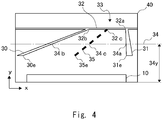
- FIG. 4 is a view showing an example of a video image where a center line is superimposed on video data in the display control system 100 according to the first example.
- the video image 40 contains a center line 35 in addition to the video data shown in Fig. 3 .
- the center line generation unit 140 calculates two points contained in the center line 35 in order to generate the center line 35. First, a specific example of a technique of calculating one of the two points contained in the center line 35 is described.
- the center line generation unit 140 recognizes the parking lines 30 to 32 from the information transmitted from the parking line recognition unit 130.
- the center line generation unit 140 calculates an intersection point 32b between the parking line 30 and the parking line 32.
- the position of the intersection point 32b is represented by the x-y coordinates (x 32b , y 32b ).
- the center line generation unit 140 calculates an intersection point 32a between the parking line 31 and the parking line 32.
- the position of the intersection point 32a is represented by the x-y coordinates (x 32a , y 32a ).
- the center line generation unit 140 calculates a midpoint 32c between the intersection point 32a and the intersection point 32b.
- the midpoint 32c is represented by the x-y coordinates ((x 32b +x 32a )/2, (y 32b +y 32a )/2).
- the center line generation unit 140 sets a virtual line 34 that is parallel to the x-axis at a position at a distance 34y from the lower end of the video image 40 in the y-direction.
- the virtual line 34 is used for the convenience of calculation to generate the center line 35, and it is not necessarily actually displayed on the video image 40.
- the distance 34y is a predetermined arbitrary distance.
- the center line generation unit 140 calculates an intersection point 34b between the parking line 30 and the virtual line 34.
- the position of the intersection point 34b is represented by the x-y coordinates (x 34b , y 34b ).
- the center line generation unit 140 calculates an intersection point 34a between the parking line 31 and the virtual line 34.
- the position of the intersection point 34a is represented by the x-y coordinates (x 34a , y 34a ).
- the center line generation unit 140 calculates a midpoint 34c between the intersection point 34a and the intersection point 34b.
- the midpoint 34c is represented by the x-y coordinates ((x 34b +x 34a )/2, (y 34b +y 34a )/2).
- the center line generation unit 140 generates the center line 35, which is a line connecting the calculated midpoint 32c and midpoint 34c.
- the center line 35 begins at the midpoint 32c and extends to an end point 35e.
- the center line 35 is a line that is virtually parallel to the parking line 30 and the parking line 31. Being virtually parallel means that a line displayed on the video image 40 is parallel if it were exist in the actual scenery captured.
- the end point 35e can be set on a line connecting an end point 30e of the parking line 30 and an end point 31e of the parking line 31, for example.
- any line type may be used.
- the width and color of the center line 35 may be selected arbitrarily so that the line is easily visible to a user. For example, the center line is not necessarily equally bold, and its width may vary from the midpoint 32c to the end point 35e.
- FIG. 5 is a view showing an example of a video image where a vehicle moving line is superimposed on video data in the display control system 100 according to the first example.
- the video image 40 in Fig. 5 contains a vehicle moving line 50 in addition to the video image described in Fig. 3 .
- the vehicle moving line 50 connects a start point 50s and an end point 50e by a straight line.
- the vehicle moving line 50 coincides with the direction when a vehicle moves in a straight line.
- the vehicle moving line 50 is a line that extends in the moving direction of the vehicle 10 from a center part 11 of the width of the vehicle 10.
- the vehicle moving line 50 extends perpendicularly from the start point 50s.
- the start point 50s is contained in the center part 11 of the vehicle 10.
- the center part 11 is a region that occupies about one-third of the width of the vehicle 10 displayed on the video image 40.
- the start point 50s may coincide with a center point 11c in the center part 11.
- the end point 50e may indicate a position where the actual distance from the vehicle 10 corresponds to a predetermined value.
- a length 50y in the y-axis direction from the start point 50s to the end point 50e corresponds to a distance of 3 meters, for example, from the center part 11 of the vehicle 10.
- the length 50y up to the end point 50e in the y-axis direction can be fixed.
- the vehicle moving line 50 is not necessarily a solid line as shown in Fig. 4 , and it may be a dashed line or a dotted line.
- the vehicle moving line 50 is not necessarily equally bold, and its width may vary from the start point 50s to the end point 50e.
- the vehicle moving line 50 does not coincide with the moving direction of the vehicle 10 depending on the mounted state of the camera 180 or the like.
- the vehicle moving line generation unit 110 may have the function that adjusts the position, angle and the like of the vehicle moving line 50 by user operation.
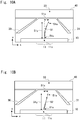
- FIGS. 6A and 6B are views showing an example of a video image where a center line and a vehicle moving line are superimposed on video data in the display control system 100 according to the first example.
- Figs. 6A and 6B show superimposed data transmitted from the display control unit 160 to the display unit 190.
- the video image 40 of Fig. 6A and the video image 40 of Fig. 6B are video images showing the parking space 33 captured by the camera 180. Note that, however, the video image 40 of Fig. 6B shows the state where the vehicle comes closer to the parking space 33 compared with the video image 40 of Fig. 6A .
- the vehicle 10 and the parking space 33 are at a certain distance from each other. Further, the vehicle 10 and the parking space 33 are at a certain angle from each other.
- the lower side of the video image 40 shows a position closer to the vehicle 10, and the upper side of the video image 40 shows a position farther from the vehicle 10.
- an object located nearby is displayed relatively larger than an object located far away. Therefore, despite that the parking line 30 and the parking line 31 are parallel in reality, they are displayed at a larger distance therebetween on the lower side of the image and displayed at a smaller distance therebetween on the upper side of the image. In this manner, an object displayed in an area close to the left or right edge of the video image 40 is displayed at an angle different from the actual angle with the vehicle 10.
- an object displayed in a center part in the horizontal direction of the video image 40 is displayed at an angle close to the actual angle with the vehicle 10.
- an angle A1 between the center line 35 and the vehicle moving line 50 is close to the actual angle between the vehicle 10 and the parking space 33. Therefore, a user can control a steering wheel by using the angle A1 as a guide.
- Fig. 6B shows a state where the vehicle 10 has come closer to the parking space 33 compared with the example shown in Fig. 6A .
- an angle A2 between the center line 35 and the vehicle moving line 50 is smaller than the angle A1 shown in Fig. 6A .
- the user can control a steering wheel by using the angle A2 as a guide. Further, the user can handle the vehicle 10 in such a way that the vehicle moving line 50 and the center line 35 overlap.
- FIG. 7 is a view showing a flowchart in the display control device 101 according to this example.
- the video data acquisition unit 120 acquires video data generated by the camera 180 (Step S100). The video data acquisition unit 120 then transmits the acquired video data to the parking line recognition unit 130 and the superimposed video generation unit 150.
- the parking line recognition unit 130 recognizes parking lines from the video data transmitted from the video data acquisition unit 120, and transmits information about the recognized parking lines to the center line generation unit 140 (Step S101). To be specific, with reference to the examples of Figs. 6A and 6B , the parking line recognition unit 130 recognizes the positions of the parking lines 30 to 32 by performing image processing.
- the center line generation unit 140 generates the center line 35 from the information transmitted from the parking line recognition unit 130, and transmits information about the generated center line 35 to the superimposed video generation unit 150 (Step S102).
- a method of generating the center line 35 is described earlier with reference to Fig. 4 , for example.
- the vehicle moving line generation unit 110 generates the vehicle moving line, and transmits information about the generated vehicle moving line to the superimposed video generation unit 150 (Step S 103).
- a method of generating the vehicle moving line is described earlier with reference to Fig. 5 , for example.
- the superimposed video generation unit 150 generates superimposed data, which is video data where the information about the center line transmitted from the center line generation unit 140 and the information about the vehicle moving line transmitted from the vehicle moving line generation unit 110 are superimposed on the video data transmitted from the video data acquisition unit 120, and transmits this superimposed data to the display control unit 160 (Step S104).
- the display control unit 160 transmits the superimposed data transmitted from the superimposed video generation unit 150 to the display unit 190, and displays the data thereon (Step S 105). After the display control unit 160 ends the transmission of the superimposed data, the process returns to Step S100, and the display control device 101 performs the acquisition of video data.
- Step S103 may be performed in parallel with Steps S100 to S102, or Step S103 may be performed before Step S102.
- the display control system 100 reduces the possibility that a parking line and a vehicle moving line overlap in the y-axis direction of the video image 40 when a driver moves a vehicle to a parking space.
- the display control system 100 according to the first example can reduce difficulty of visually determining a parking line. Further, it is possible to provide the display control system that supports intuitive vehicle handling by intending to make the vehicle moving line coincide with the center line 35.
- a second embodiment is described hereinafter.
- a display control system 200 according to the second embodiment is different from the display control system 100 according to the first example in the way of displaying a center line. Further, the display control system 200 according to the second embodiment is different from the first example in that a vehicle moving line can be in synchronization with the motion of a vehicle.
- Fig. 8 is a functional block diagram of the display control system 200 according to the second embodiment.
- the display control system 200 according to the second embodiment is different from the display control system 100 according to the first example in that a display control device 201 includes a vehicle motion acquisition unit 270. Elements different from those of the first example are described hereinafter in detail.
- the display control device 201 includes the vehicle motion acquisition unit 270, a vehicle moving line generation unit 210, a video data acquisition unit 120, a parking line recognition unit 130, a center line generation unit 140, a superimposed video generation unit 150, and a display control unit 260.
- the vehicle motion acquisition unit 270 receives motion information, which is information about the motion of a vehicle from a CAN or the like, which is an in-car network.
- the motion information is information containing some or all of information indicating to which range the transmission of a vehicle is set, information indicating the steering angle of a vehicle, and information indicating the traveling speed of a vehicle.
- the vehicle motion acquisition unit 270 acquires a predetermined signal among signals transmitted from a CAN or the like, and transmits this signal to the vehicle moving line generation unit 210 or the display control unit 260. By receiving the motion information, the vehicle motion acquisition unit 270 can acquire that the transmission is set to the reverse range, for example.
- the vehicle motion acquisition unit 270 can acquire that the transmission is set to the low-speed driving range, for example. Furthermore, the vehicle motion acquisition unit 270 can acquire information indicating the steering angle of a vehicle and monitor the angle of the steering wheel of the vehicle. The vehicle motion acquisition unit 270 can acquire information indicating the traveling speed of a vehicle and monitor the traveling speed of the vehicle.
- the vehicle moving line generation unit 210 receives the motion information transmitted from the vehicle motion acquisition unit 270. Then, the vehicle moving line generation unit 210 generates a vehicle moving line based on the motion information transmitted from the vehicle motion acquisition unit 270.
- the vehicle moving line is line information indicating the planned moving path of a vehicle by being superimposed on video data captured by the camera 180.
- the vehicle moving line generation unit 210 calculates an expected path based on information indicating the steering angle transmitted from the vehicle motion acquisition unit 270, for example.
- the vehicle moving line generation unit 210 generates the vehicle moving line from the calculated expected path.
- An arbitrary existing technique may be applied to the generation of the vehicle moving line by the vehicle moving line generation unit 210.
- the vehicle moving line generation unit 210 calculates one point or two or more points as expected path points. Then, the vehicle moving line generation unit 210 generates information of the vehicle moving line that passes through the expected path points by a predetermined method.
- An example of the vehicle moving line is line information indicating lines that extend the vehicle width when the vehicle moves in a straight line.
- Another example of the vehicle moving line is line information associated with the steering angle of the vehicle.
- the vehicle moving line generation unit 210 transmits information about the generated vehicle moving line to the superimposed video generation unit 150.
- the vehicle moving line generation unit 210 generates and transmits information about one or a plurality of vehicle moving lines among the above-described vehicle moving lines.
- the display control unit 260 receives the superimposed data transmitted from the superimposed video generation unit 150.
- the display control unit 260 transmits the received superimposed data to the display unit 190.
- the display control unit 260 may transmit the superimposed data to the display unit 190 or stop transmitting the superimposed data in response to an instruction from a display instruction unit, which is not shown, for example.
- the display control unit 260 may monitor the vehicle motion acquisition unit 270, and transmit the video data or the superimposed data to the display unit 190 or stop transmitting those data in accordance with information acquired by the vehicle motion acquisition unit 270. Further, the display control unit 260 may connect to the vehicle motion acquisition unit 270 and acquire vehicle motion information.
- Fig. 9 is a view showing an example of a video image where a center line is superimposed on video data in the display control system 200 according to the second embodiment.
- the video image 40 of Fig. 9 includes a first center limit line 36 and a second center limit line 37 adjacent to the center line 35, in addition to the center line 35.
- the center line generation unit 140 sets a virtual line 34 that is parallel to the x-axis at a position at a distance 34y from the lower end of the video image 40 in the y-direction.
- the virtual line 34 is used for the convenience of calculation to generate the center line 35, and it is not necessarily actually displayed on the video image 40.
- a distance from the vehicle 10 in the video data which coincides with the virtual line 34 is previously set.
- the position that coincides with the virtual line 34 in the video image 40 of Fig. 9 can be previously set to 3 meters from the rear end of the vehicle 10, for example.
- the center line generation unit 140 can estimate a distance in the width direction of the video data at such a distance previously set. Specifically, the center line generation unit 140 can estimate a distance between an intersection point 34b and an intersection point 34a. The distance between the intersection point 34b and the intersection point 34a is the width of the parking space 33.
- the center line generation unit 140 previously stores the width of the vehicle 10.
- the center line generation unit 140 can calculate a difference between the width of the parking space 33 and the width of the vehicle 10.
- the width of the parking space 33 is generally larger than the width of the vehicle 10. Therefore, the difference between the width of the parking space 33 and the width of the vehicle 10 can be regarded as a possible parking range 38 when parking the vehicle 10 in the parking space 33.
- the center line generation unit 140 divides the calculated possible parking range 38 into two parts. Then, the center line generation unit 140 sets, on the virtual line 34, a first limit point 34d and a second limit point 34e, which are points at equal distances from a midpoint 34c, which is an intersection point between the center line 35 and the virtual line 34, in the possible parking range 38. Therefore, the distance between the first limit point 34d and the second limit point 34e corresponds to the possible parking range 38 when parking the vehicle 10 in the parking space 33.
- the first center limit line 36 can be displayed as a line that passes through the first limit point 34d and that is virtually parallel to the parking line 30, the parking line 31 and the center line 35.
- the second center limit line 37 can be displayed as a line that passes through the second limit point 34e and that is virtually parallel to the parking line 30, the parking line 31 and the center line 35.
- a vehicle moving line in the display control system 200 according to the second embodiment is described hereinafter with reference to Figs. 10A and 10B .
- the vehicle moving line generation unit 110 generates a vehicle moving line that extends along a planned moving path in accordance with the steering angle from a center part along the width of the vehicle 10.
- Figs. 10A and 10B are views showing an example of a video image where a vehicle moving line is superimposed on video data in the display control system 200 according to the second embodiment.
- the video image 40 in Fig. 10A contains a vehicle moving line 51 in addition to the video image described in Fig. 3 .
- the vehicle moving line 51 extends along a planned moving path in accordance with the steering angle from a center part 11 of the width of the vehicle 10.
- the vehicle moving line 51 is line information indicating an expected driving path of the vehicle 10 in accordance with the steering angle of the vehicle 10.
- the vehicle moving line 51 is a curved line in accordance with the steering angle of the vehicle 10 except when the vehicle 10 is moving in a straight line.
- the curvature of the vehicle moving line 51 is larger as the steering angle of the vehicle 10 is larger.
- a vehicle moving line 52 superimposed on the video image 40 shown in Fig. 10B is a straight line.
- the vehicle moving line 52 extends linearly along a planned moving path in accordance with the steering angle from a start point 51s coinciding with the center part 11 of the vehicle 10.
- the vehicle moving line 52 connects the start point 51s and an end point 51e by a straight line.
- the vehicle moving line 52 draws a straight line parallel to the y-axis when the vehicle 10 is moving in a straight line.
- the angle between the vehicle moving line 52 and the y-axis is larger as the steering angle of the vehicle 10 is larger.
- the start point 51s is contained in the center part 11 of the vehicle 10.
- the center part 11 is a region that occupies about one-third of the width of the vehicle 10 displayed on the video image 40.
- the start point 50s may coincide with a center point 11c in the center part 11.
- the end point 51e is a point on a curved line extending from the start point 51s along the planned moving path in accordance with the steering angle of the vehicle.
- the end point 51e may indicate a position where the actual distance from the vehicle 10 corresponds to a predetermined value.
- a length 51y in the y-axis direction from the start point 51s to the end point 51e corresponds to a distance of 3 meters, for example, from the center part 11 of the vehicle 10.
- the length 51y up to the end point 51e in the y-axis direction can be fixed.
- the position of the end point 51e in the x-axis direction varies depending on the steering angle of the vehicle 10. As the steering angle of the vehicle 10 is larger, the absolute value of a length 51x in the x-axis direction increases.
- the vehicle moving line 52 When the steering direction of the vehicle 10 is right in the video image 40, the vehicle moving line 52 extends from the center part 11 in the y-axis positive direction and the x-axis positive direction. Likewise, when the steering direction of the vehicle 10 is left in the video image 40, the vehicle moving line 52 extends from the center part 11 in the y-axis positive direction and the x-axis negative direction.
- the length 51y up to the end point 51e in the y-axis direction may remain unfixed, and it may change to draw a circle or an ellipse around the start point 51s.
- the length 51y up to the end point 51e in the y-axis direction may remain unfixed, and it may change in such a way that the length of the vehicle moving line 52 is substantially the same even when the steering angle changes.
- the vehicle moving lines 51 and 52 are not necessarily a solid line as shown in Figs. 10A and 10B , and they may be a dashed line or a dotted line.
- the vehicle moving lines 51 and 52 are not necessarily equally bold, and their width may vary from the start point 51s to the end point 51e.
- Fig. 11 is a view showing an example of a video image where a vehicle moving line and a center limit line are superimposed on video data in the display control system 200 according to the second embodiment.
- the video image 40 of Fig. 11 contains a parking space 33, a center line 35, a first center limit line 36, a second center limit line 37 and a vehicle moving line 51.
- Fig. 11 the vehicle 10 is moving toward the parking space 33.
- the condition that the vehicle moving line 51 is located between the first center limit line 36 and the second center limit line 37 indicates that the vehicle 10 is located between the parking line 30 and the parking line 31.
- a user can handle the vehicle with an intention to maintain the vehicle moving line 51 between the first center limit line 36 and the second center limit line 37.
- a user can handle the vehicle with an intention to make the vehicle moving line 51 coincide with the center line 35 by controlling a steering wheel.
- Fig. 11 shows an example in which the center line 35 is displayed, the first center limit line 36 and the second center limit line 37 may be displayed without displaying the center line 35.
- Fig. 12 is a view showing an example of a video image where a distance indicator line is further superimposed on video data in the display control system 200 according to the second embodiment.
- the video image 40 in Fig. 12 contains a distance indicator line 53 in addition to the example of the video image 40 in Fig. 11 .
- the distance indicator line 53 is line information extending in the horizontal direction of the video image 40, which is the direction parallel to the x-axis.
- the distance indicator line 53 indicates a predetermined distance from the end of the vehicle 10.
- the distance indicator line 53 indicates a distance of 0.4 meter from the rear end of the vehicle 10, for example.
- a user can move the vehicle 10 with an intention to make the distance indicator line 53 coincide with the parking line 32.
- the distance indicator line 53 may be displayed as a plurality of lines indicating a plurality of distances such as 2 m, 1 m and 0.4 m, for example. With this distance indicator line 53, a user can intuitively recognize the distance between the vehicle 10 and the parking line 32.
- FIG. 13 is a view showing a flowchart in the display control device 201 according to the second embodiment.
- the flowchart in the display control device 201 is the same as the flowchart in the display control device 101 in the processing from Step S100 to S105. Different processing from the flowchart in the display control device 101 is described hereinbelow.
- the vehicle motion acquisition unit 270 acquires information about the setting of the transmission of the vehicle 10 from a CAN or the like, which is an in-car network (Step S200).
- the display control unit 160 acquires the information about the setting of the transmission of the vehicle 10 acquired by the vehicle motion acquisition unit 270, and determines whether the vehicle 10 is to move backward or not (Step S201).
- the display control unit 160 determines whether an instruction to end video display is received or not (Step S202).
- the display control unit 160 ends the process.
- the process returns to Step S200, and the vehicle motion acquisition unit 270 acquires information about the setting of the transmission of the vehicle 10 again.
- Step S201 when the vehicle 10 is moving backward, which is, when the setting of the transmission of the vehicle 10 is a reverse range (Yes in Step S201), the display control unit 160 performs processing of transmitting superimposed data to the display unit 190 (Step S100 to Step S105).
- the display unit 160 determines whether an instruction to end video display is received or not (Step S202). When an instruction to end video display is received (Yes in Step S202), the display control unit 160 ends the process.
- Step S202 when an instruction to end video display is not received (No in Step S202), the display control device 201 returns to Step S200, and the vehicle motion acquisition unit 270 acquires information about the setting of the transmission of the vehicle 10 again.
- the display control system 200 according to the second embodiment reduces the possibility that a parking line and a vehicle moving line overlap in the y-axis direction of the video image 40 when a driver moves a vehicle to a parking space.
- the display control system 200 according to the second embodiment can reduce difficulty of visually determining a parking line.
- the present invention is not restricted to the above-described embodiment, and various changes and modifications may be made without departing from the scope of the invention (which is defined by the appended claims).
- the above-described embodiment may be applied to the case where the vehicle 10 moves forward to the parking space 33.
- the display control device 201 can superimpose the vehicle moving line on data of a video captured by the forward camera 180F of the vehicle 10.
- the display control device 201 can acquire that the vehicle 10 is moving forward at a speed slower than a predetermined traveling speed, for example.
- the display control device 201 may start a first display mode in response to an instruction from a driver, which is not shown.
- vehicle moving line 51 or the vehicle moving line 52 described in the second embodiment may be applied to the display control system 100 according to the first example.
- a recording control device can be used to acquire a video around a vehicle in motion, for example.
Landscapes
- Engineering & Computer Science (AREA)
- Multimedia (AREA)
- Mechanical Engineering (AREA)
- Signal Processing (AREA)
- Physics & Mathematics (AREA)
- Theoretical Computer Science (AREA)
- General Physics & Mathematics (AREA)
- Chemical & Material Sciences (AREA)
- Computer Vision & Pattern Recognition (AREA)
- Transportation (AREA)
- Combustion & Propulsion (AREA)
- Closed-Circuit Television Systems (AREA)
- Image Analysis (AREA)
- Traffic Control Systems (AREA)
- Controls And Circuits For Display Device (AREA)
Description
- The present invention relates to a display control device, a display control system, a display control method, and a display control program.
- A technique that, when a vehicle is moving backward, superimposes a guide line indicating a predicted path of backward motion on a rearward video image captured using a rear camera mounted at the back of the vehicle and displays this video image on a display unit such as a monitor to easily and accurately guide the vehicle to a parking space has become popular recently.
- For example, the vehicle-mounted imaging device disclosed in Patent Literature 1 takes a video showing the back of a vehicle at the time of parking the vehicle, for example, and displays the video image showing the back of the vehicle on an in-vehicle monitor, and further superimposes a predicted path in the moving direction of the vehicle on this video image showing the back of the vehicle.
- PTL1:
Japanese Unexamined Patent Application Publication No. 2011-211432 -
US 2008/158011 A1 relates to a parking assist apparatus for assisting a parking operation of a vehicle, the apparatus including an image capturing portion, a displaying portion, a guiding portion, and a superimposing portion. -
US 2016/094807 A1 relates to an image processing apparatus, a processor of the apparatus being configured to generate a support image by superimposing a derived trace line and a derived prediction line on an acquired photographic image of a region near a host vehicle, and displaying the support image in the host vehicle. -
Fig. 14 shows an example of the related art. Avideo image 40 shown in this example is a video image captured using a rear camera mounted at the back of a vehicle, on which aguide line 70 indicating a predicted path of the vehicle's backward motion is superimposed. A driver is moving avehicle 10 to aparking space 33 that includesparking lines guide line 70 corresponds to the width of thevehicle 10 and is drawn along an intended path of the vehicle. Theparking line 30 and theguide line 70 overlap. - As described above, in the related art, a guide line superimposed on a rearward video image overlaps a parking line in some cases. In such cases, it is difficult for a driver to find out the parking line in the displayed video image. Thus, there are cases where it is difficult for a driver to grasp the positional relationship between a vehicle and a parking space.
- The present embodiment has been accomplished to solve the above problems and an object of the present invention is thus to provide a display control device, a display control system, a display control method, and a display control program that support intuitive vehicle handling by reducing difficulty of visually determining a parking line displayed on a display unit.
- A display control device according to an embodiment includes a video data acquisition unit configured to acquire video data from a camera that captures a video in a moving direction of a vehicle, a parking line recognition unit configured to recognize a parking line being a line of a parking space from the video data, a center line generation unit configured to generate a center line of the parking space based on the recognized parking line, and two center limit lines having a distance from the center line corresponding to a difference along the width between the parking line and the vehicle, the difference being calculated based on the recognized parking line and the width of the vehicle registered in advance, a vehicle moving line generation unit configured to generate a vehicle moving line extending in the moving direction of the vehicle from a position corresponding to a center part along a width of the vehicle, a superimposed video generation unit configured to generate superimposed data being video data where the center line, the center limit lines and the vehicle moving line are superimposed on the video data, and a display control unit configured to transmit the superimposed data to a display unit so as to display a video related to the superimposed data on the display unit.
- A display control method according to an embodiment includes acquiring video data from a camera that captures a video in a moving direction of a vehicle, recognizing a parking line being a line of a parking space from the video data, generating a center line of the parking space from the recognized parking line, and two center limit lines having a distance from the center line corresponding to a difference along the width between the parking line and the vehicle, the difference being calculated based on the recognized parking line and the width of the vehicle registered in advance, generating a vehicle moving line extending in the moving direction of the vehicle from a position corresponding to a center part along a width of the vehicle, generating superimposed data being video data where the center line, the center limit lines and the vehicle moving line are superimposed on the video data, and transmitting the superimposed data to a display unit so as to display a video related to the superimposed data on the display unit.
- A display control program according to an embodiment causes a computer to execute acquiring video data from a camera that captures a video in a moving direction of a vehicle, recognizing a parking line being a line of a parking space from the video data, generating a center line of the parking space from the recognized parking line, and two center limit lines having a distance from the center line corresponding to a difference along the width between the parking line and the vehicle, the difference being calculated based on the recognized parking line and the width of the vehicle registered in advance, generating a vehicle moving line extending in the moving direction of the vehicle from a position corresponding to a center part along a width of the vehicle, generating superimposed data being video data where the center line, the center limit lines and the vehicle moving line are superimposed on the video data, and transmitting the superimposed data to a display unit so as to display a video related to the superimposed data on the display unit.
- According to the embodiment, it is possible to provide a display control device, a display control system, a display control method, and a display control program that support intuitive vehicle handling by reducing difficulty of visually determining a parking line displayed on a display unit.
-
-
Fig. 1 is a functional block diagram of adisplay control system 100 according to a first example. -
Fig. 2 is a top view showing an example of a state where avehicle 10 on which thedisplay control system 100 is mounted is moving to a parking space. -
Fig. 3 is a view showing an example of a video image where video data captured using a camera in thevehicle 10 is displayed on adisplay unit 190. -
Fig. 4 is a view showing an example of a video image where a center line is superimposed on video data in thedisplay control system 100 according to the first example. -
Fig. 5 is a view showing an example of a video image where a vehicle moving line is superimposed on video data in thedisplay control system 100 according to the first example. -
Fig. 6A is a view showing an example of a video image where a center line and a vehicle moving line are superimposed on video data in thedisplay control system 100 according to the first example. -
Fig. 6B is a view showing an example of a video image where a center line and a vehicle moving line are superimposed on video data in thedisplay control system 100 according to the first example. -
Fig. 7 is a view showing a flowchart in adisplay control device 101 according to the first example. -
Fig. 8 is a functional block diagram of adisplay control system 200 according to a second embodiment. -
Fig. 9 is a view showing an example of a video image where a center line is superimposed on video data in thedisplay control system 200 according to the second embodiment. -
Fig. 10A is a view showing an example of a video image where a vehicle moving line is superimposed on video data in thedisplay control system 200 according to the second embodiment. -
Fig. 10B is a view showing an example of a video image where a vehicle moving line is superimposed on video data in thedisplay control system 200 according to the second embodiment. -
Fig. 11 is a view showing an example of a video image where a vehicle moving line and a center limit line are superimposed on video data in thedisplay control system 200 according to the second embodiment. -
Fig. 12 is a view showing an example of a video image where a distance indicator line is further superimposed on video data in thedisplay control system 200 according to the second embodiment. -
Fig. 13 is a view showing a flowchart in adisplay control device 201 according to the second embodiment. -
Fig. 14 is a view showing an example of a rearward video in a related art. - A first example of the present disclosure is described hereinafter with reference to the drawings.
Fig. 1 is a functional block diagram of adisplay control system 100 according to the first example. The following description and the drawings are appropriately shortened and simplified to clarify the explanation. In the figures, the identical reference symbols denote identical structural elements, and the redundant explanation thereof is omitted. - The
display control system 100 is a system that, when a driver is moving a vehicle to a parking space or the like, superimposes a center line of the parking space and a vehicle moving line indicating the moving direction of the vehicle on a video image captured by acamera 180 that takes a video of a vehicle moving direction and displays this video image on adisplay unit 190. Thedisplay control system 100 may be implemented as one function of a car navigation system, a dashboard camera or the like which can be retrofitted to a vehicle, for example. Further, adisplay control device 101 may be implemented as one function of a system incorporated into a vehicle when assembling the vehicle in a factory, for example. Furthermore, thedisplay control device 101 may be implemented by combining a system incorporated into a vehicle when assembling the vehicle in a factory and a device that can be retrofitted to a vehicle, for example. Thedisplay control system 100 includes thedisplay control device 101 and at least one of thecamera 180 and thedisplay unit 190. - The
display control device 101 acquires video data, which is data of a video captured by thecamera 180, superimposes a vehicle moving line on this data and displays the data on thedisplay unit 190. Thedisplay control device 101 may be implemented as a device in various forms such as a computer device that operates when a processor executes a program stored in a memory. The processor may be a micro processor, an MPU (Micro Processing Unit), or a CPU (Central Processing Unit), for example. The memory is a volatile memory or a nonvolatile memory, and it may be a combination of a volatile memory and a nonvolatile memory. The processor executes one or a plurality of programs including a group of instructions for causing a computer to perform processing according to an example. Thedisplay control device 101 is connected with a CAN (Controller Area Network) or the like, which is an in-car network. Further, thedisplay control device 101 is connected with thecamera 180 and thedisplay unit 190. The CAN or the like means that it may be an in-car network such as MOST (Media Oriented Systems Transport) or Ethernet (registered trademark), not limited to the CAN. - Further, the program can be stored and provided to the computer using any type of non-transitory computer readable medium. The non-transitory computer readable medium includes any type of tangible storage medium. Examples of the non-transitory computer readable medium include magnetic storage media (such as floppy disks, magnetic tapes, hard disk drives, etc.), optical magnetic storage media (e.g. magneto-optical disks), CD-ROM (Read Only Memory), CD-R , CD-R/W, and semiconductor memories (such as mask ROM, PROM (Programmable ROM), EPROM (Erasable PROM), flash ROM, RAM (Random Access Memory), etc.). The program may be provided to a computer using any type of transitory computer readable medium. Examples of the transitory computer readable medium include electric signals, optical signals, and electromagnetic waves. The transitory computer readable medium can provide the program to a computer via a wired communication line such as an electric wire or optical fiber or a wireless communication line.
- The
display control device 101 is described hereinafter in detail. Thedisplay control device 101 includes a vehicle movingline generation unit 110, a videodata acquisition unit 120, a parkingline recognition unit 130, a centerline generation unit 140, a superimposedvideo generation unit 150, and adisplay control unit 160. - The vehicle moving
line generation unit 110 generates a vehicle moving line that extends in the moving direction of the vehicle from a center part along the width of a vehicle. The vehicle moving line is line information indicating the moving direction of the vehicle by being superimposed on video data captured by thecamera 180. An example of a method of generating the vehicle moving line in the vehicle movingline generation unit 110 is schematically described below. Thecamera 180 is placed at the center part along the width of a vehicle so as to take a video in the moving direction of the vehicle. Thus, the vehicle movingline generation unit 110 generates the vehicle moving line where the initial setting is such that thecamera 180 is placed at the center part along the width of a vehicle so as to take a video in the moving direction of the vehicle. The initial setting is a setting that displays a predetermined length of line extending vertically from the center part along the width in the underside of a screen of thedisplay unit 190. Thedisplay control system 100 may have the function that allows a user to adjust the position, angle, length and the like of the vehicle moving line. The vehicle movingline generation unit 110 transmits information about the generated vehicle moving line to the superimposedvideo generation unit 150. - The video
data acquisition unit 120 acquires the video data generated in thecamera 180. The videodata acquisition unit 120 acquires digital video data or analog video data from thecamera 180. The video data acquisition unit transmits the video data to the superimposedvideo generation unit 150 as uncompressed digital video data or compressed video data in a format such as H.264 or H.265, for example. Further, the videodata acquisition unit 120 may generate video data in a compressed video format such as MPEG (Moving Picture Experts Group) 2-TS (Transport Stream) or AVI (Audio Video Interleave). The videodata acquisition unit 120 transmits the video data to the superimposedvideo generation unit 150. Note that it is arbitrary in which block compression is to be performed or whether data is to be compressed or uncompressed, and compressed video data may be acquired from a camera unit, for example. - The parking
line recognition unit 130 recognizes parking lines displayed in a parking space from the video data transmitted from the videodata acquisition unit 120. A specific example of a technique of recognizing parking lines in the parkingline recognition unit 130 is described below. The parkingline recognition unit 130 calculates a luminance gradient of each pixel of the video data, for example. The parkingline recognition unit 130 then recognizes parking lines by using a predetermined technique such as edge detection. A technique of calculating a luminance gradient of each pixel of video data and recognizing a target object is a known technique. Thus, the detailed description thereof is omitted. The parkingline recognition unit 130 recognizes parking lines and thereby generates information about whether parking lines exist in the video data and the positions of parking lines in the video data. The parkingline recognition unit 130 transmits the generated information to the centerline generation unit 140. Further, when the parkingline recognition unit 130 does not recognize any parking line, it may transmit information indicating that no parking line is contained in the video data to the centerline generation unit 140. - The center
line generation unit 140 generates a center line of the parking space based on the information transmitted from the parkingline recognition unit 130. The center line of the parking space is a line extending in parallel to the middle of two parallel parking lines drawn on the left and right sides of a vehicle parked position among the parking lines drawn in the parking space. The centerline generation unit 140 transmits information about the generated center line to the superimposedvideo generation unit 150. - The superimposed
video generation unit 150 receives each of the information transmitted from the vehicle movingline generation unit 110, the video data transmitted from the videodata acquisition unit 120, and the information transmitted from the parkingline recognition unit 130. The superimposedvideo generation unit 150 then generates video data on which the vehicle moving line and the center line are superimposed. The video data generated by the superimposedvideo generation unit 150 is referred to hereinafter as superimposed data. The superimposedvideo generation unit 150 transmits the generated superimposed data to thedisplay control unit 160. - The
display control unit 160 receives the superimposed data transmitted from the superimposedvideo generation unit 150. Thedisplay control unit 160 transmits the received superimposed data to thedisplay unit 190. Thedisplay control unit 160 may transmit the superimposed data to thedisplay unit 190 or stop transmitting the superimposed data in response to an instruction from a display instruction unit, which is not shown, for example. - The
display control unit 160 may process the received superimposed data so as to change the viewing angle of a video image to be displayed on the display unit. Further, thedisplay control unit 160 may process the received superimposed data so as to perform distortion correction of a video image to be displayed on the display unit. Furthermore, thedisplay control unit 160 may process the received superimposed data so as to change a video image to be displayed on the display unit to a video image viewed from the top of the vehicle. Thedisplay control unit 160 may process the received superimposed data so as to change a video image to be displayed on the display unit in a way not limited the above. - The
display control device 101 may include an acquisition unit, which is not shown, and acquire vehicle motion information by being connected with a CAN or the like or receiving information from a sensor or the like. In this case, thedisplay control unit 160 may transmit the superimposed data to thedisplay unit 190 or stop transmitting the superimposed data in accordance with the vehicle motion information acquired by the acquisition unit, which is not shown. Further, thedisplay control device 101 may include an acquisition unit, which is not shown, and acquire a user instruction. In this case, thedisplay control unit 160 may transmit the superimposed data to thedisplay unit 190 or stop transmitting the superimposed data in accordance with the information acquired by the acquisition unit, which is not shown. - The
camera 180 generates video data that shows a frontward or rearward video of a vehicle. Thecamera 180 may be placed on the front of a vehicle. Thecamera 180 may be placed on the back of a vehicle. Further, thecamera 180 may be placed on each of the front of a vehicle and the back of the vehicle. Thecamera 180 transmits the generated video data to the videodata acquisition unit 120 in thedisplay control device 101. - The
display unit 190 displays the video data or superimposed data received from thedisplay control unit 160 in thedisplay control device 101. Thedisplay unit 190 is a display device such as a liquid crystal display device, an organic EL (organic electro-luminescence) display device, or a head-up display, for example. Thedisplay unit 190 is placed at a position that can be viewed by a driver while handling a vehicle. The position that can be viewed by a driver while handling a vehicle is a position on a center console, on a dashboard, on a meter panel, on a rear-view mirror, near a steering wheel, on a windshield or the like, for example. - A vehicle on which the
display control system 100 is mounted is described hereinafter with reference toFig. 2. Fig. 2 is a top view showing an example of a state where avehicle 10 on which thedisplay control system 100 is mounted is moving to a parking space. Thevehicle 10 includes thedisplay control device 101 at an arbitrary position. Thevehicle 10 also includes a forward camera 180F and a rearward camera 180R. Thevehicle 10 further includes thedisplay unit 190 at a position that can be viewed by a driver while handling the vehicle. InFig. 2 , thevehicle 10 is moving backward toward aparking space 33. Theparking space 33 includesparking lines 30 to 32. The driver is trying to move thevehicle 10 to a position surrounded by theparking lines 30 to 32. In this case, thedisplay control system 100 acquires data of a video captured by the rearward camera 180R. - The video data captured by the camera of the
vehicle 10 is described hereinafter.Fig. 3 is a view showing an example of a video image where video data captured by a camera in thevehicle 10 is displayed on thedisplay unit 190. Avideo image 40 contains a part of thevehicle 10 and theparking space 33. Theparking space 33 contains theparking lines 30 to 32. The lower side of thevideo image 40 shows a position closer to thevehicle 10, and the upper side of thevideo image 40 shows a position farther from thevehicle 10. -
Fig. 3 contains x-y coordinates. InFig. 3 , the x-coordinate indicates the horizontal direction of thevideo image 40. The rightward direction ofFig. 3 is the positive direction of the x-axis. InFig. 3 , the y-coordinate indicates the vertical direction of thevideo image 40. The upward direction ofFig. 3 is the positive direction of the y-axis. The x-y coordinates inFig. 3 are shown for the convenience of explaining the positional relationship of elements. The x-y coordinates in the subsequent figures are shown for the same purpose as the x-y coordinates inFig. 3 . - A specific example of a technique of generating a center line in the center
line generation unit 140 is described hereinafter with reference toFig. 4. Fig. 4 is a view showing an example of a video image where a center line is superimposed on video data in thedisplay control system 100 according to the first example. InFig. 4 , thevideo image 40 contains acenter line 35 in addition to the video data shown inFig. 3 . - The center
line generation unit 140 calculates two points contained in thecenter line 35 in order to generate thecenter line 35. First, a specific example of a technique of calculating one of the two points contained in thecenter line 35 is described. The centerline generation unit 140 recognizes theparking lines 30 to 32 from the information transmitted from the parkingline recognition unit 130. The centerline generation unit 140 calculates anintersection point 32b between theparking line 30 and theparking line 32. The position of theintersection point 32b is represented by the x-y coordinates (x32b, y32b). Further, the centerline generation unit 140 calculates anintersection point 32a between theparking line 31 and theparking line 32. The position of theintersection point 32a is represented by the x-y coordinates (x32a, y32a). Then, the centerline generation unit 140 calculates a midpoint 32c between theintersection point 32a and theintersection point 32b. The midpoint 32c is represented by the x-y coordinates ((x32b+x32a)/2, (y32b+y32a)/2). - A specific example of a technique of calculating the other one of the two points contained in the
center line 35 is described next. The centerline generation unit 140 sets avirtual line 34 that is parallel to the x-axis at a position at adistance 34y from the lower end of thevideo image 40 in the y-direction. Thevirtual line 34 is used for the convenience of calculation to generate thecenter line 35, and it is not necessarily actually displayed on thevideo image 40. Further, thedistance 34y is a predetermined arbitrary distance. The centerline generation unit 140 calculates an intersection point 34b between theparking line 30 and thevirtual line 34. The position of the intersection point 34b is represented by the x-y coordinates (x34b, y34b). Further, the centerline generation unit 140 calculates anintersection point 34a between theparking line 31 and thevirtual line 34. The position of theintersection point 34a is represented by the x-y coordinates (x34a, y34a). Then, the centerline generation unit 140 calculates amidpoint 34c between theintersection point 34a and the intersection point 34b. Themidpoint 34c is represented by the x-y coordinates ((x34b+x34a)/2, (y34b+y34a)/2). - The center
line generation unit 140 generates thecenter line 35, which is a line connecting the calculated midpoint 32c andmidpoint 34c. Thecenter line 35 begins at the midpoint 32c and extends to anend point 35e. Thecenter line 35 is a line that is virtually parallel to theparking line 30 and theparking line 31. Being virtually parallel means that a line displayed on thevideo image 40 is parallel if it were exist in the actual scenery captured. Theend point 35e can be set on a line connecting anend point 30e of theparking line 30 and anend point 31e of theparking line 31, for example. Note that, although thecenter line 35 is indicated by a dashed line inFig. 4 , any line type may be used. The width and color of thecenter line 35 may be selected arbitrarily so that the line is easily visible to a user. For example, the center line is not necessarily equally bold, and its width may vary from the midpoint 32c to theend point 35e. - A vehicle moving line is described hereinafter with reference to
Fig. 5. Fig. 5 is a view showing an example of a video image where a vehicle moving line is superimposed on video data in thedisplay control system 100 according to the first example. Thevideo image 40 inFig. 5 contains avehicle moving line 50 in addition to the video image described inFig. 3 . Thevehicle moving line 50 connects astart point 50s and anend point 50e by a straight line. Thevehicle moving line 50 coincides with the direction when a vehicle moves in a straight line. Specifically, thevehicle moving line 50 is a line that extends in the moving direction of thevehicle 10 from acenter part 11 of the width of thevehicle 10. Thevehicle moving line 50 extends perpendicularly from thestart point 50s. - The
start point 50s is contained in thecenter part 11 of thevehicle 10. Thecenter part 11 is a region that occupies about one-third of the width of thevehicle 10 displayed on thevideo image 40. Thestart point 50s may coincide with acenter point 11c in thecenter part 11. - The
end point 50e may indicate a position where the actual distance from thevehicle 10 corresponds to a predetermined value. In thevideo image 40, alength 50y in the y-axis direction from thestart point 50s to theend point 50e corresponds to a distance of 3 meters, for example, from thecenter part 11 of thevehicle 10. In this case, thelength 50y up to theend point 50e in the y-axis direction can be fixed. - The
vehicle moving line 50 is not necessarily a solid line as shown inFig. 4 , and it may be a dashed line or a dotted line. Thevehicle moving line 50 is not necessarily equally bold, and its width may vary from thestart point 50s to theend point 50e. - Note that, in some cases, the
vehicle moving line 50 does not coincide with the moving direction of thevehicle 10 depending on the mounted state of thecamera 180 or the like. In such a case, the vehicle movingline generation unit 110 may have the function that adjusts the position, angle and the like of thevehicle moving line 50 by user operation. - An example of a video image on which a center line and a vehicle moving line are superimposed is described hereinafter with reference to
Figs. 6A and 6B. Figs. 6A and 6B are views showing an example of a video image where a center line and a vehicle moving line are superimposed on video data in thedisplay control system 100 according to the first example. In other words,Figs. 6A and 6B show superimposed data transmitted from thedisplay control unit 160 to thedisplay unit 190. Thevideo image 40 ofFig. 6A and thevideo image 40 ofFig. 6B are video images showing theparking space 33 captured by thecamera 180. Note that, however, thevideo image 40 ofFig. 6B shows the state where the vehicle comes closer to theparking space 33 compared with thevideo image 40 ofFig. 6A . - In
Fig. 6A , thevehicle 10 and theparking space 33 are at a certain distance from each other. Further, thevehicle 10 and theparking space 33 are at a certain angle from each other. The lower side of thevideo image 40 shows a position closer to thevehicle 10, and the upper side of thevideo image 40 shows a position farther from thevehicle 10. In thevideo image 40, an object located nearby is displayed relatively larger than an object located far away. Therefore, despite that theparking line 30 and theparking line 31 are parallel in reality, they are displayed at a larger distance therebetween on the lower side of the image and displayed at a smaller distance therebetween on the upper side of the image. In this manner, an object displayed in an area close to the left or right edge of thevideo image 40 is displayed at an angle different from the actual angle with thevehicle 10. Thus, it is difficult for a user to intuitively grasp an angle between theparking line 30 or theparking line 31 and thevehicle 10. - On the other hand, an object displayed in a center part in the horizontal direction of the
video image 40 is displayed at an angle close to the actual angle with thevehicle 10. In the case ofFig. 6A , an angle A1 between thecenter line 35 and thevehicle moving line 50 is close to the actual angle between thevehicle 10 and theparking space 33. Therefore, a user can control a steering wheel by using the angle A1 as a guide. -
Fig. 6B shows a state where thevehicle 10 has come closer to theparking space 33 compared with the example shown inFig. 6A . InFig. 6B , an angle A2 between thecenter line 35 and thevehicle moving line 50 is smaller than the angle A1 shown inFig. 6A . Thus, the user can control a steering wheel by using the angle A2 as a guide. Further, the user can handle thevehicle 10 in such a way that thevehicle moving line 50 and thecenter line 35 overlap. - A process of the
display control device 101 according to the first example is described hereinafter with reference toFig. 7. Fig. 7 is a view showing a flowchart in thedisplay control device 101 according to this example. - First, the video
data acquisition unit 120 acquires video data generated by the camera 180 (Step S100). The videodata acquisition unit 120 then transmits the acquired video data to the parkingline recognition unit 130 and the superimposedvideo generation unit 150. - Next, the parking
line recognition unit 130 recognizes parking lines from the video data transmitted from the videodata acquisition unit 120, and transmits information about the recognized parking lines to the center line generation unit 140 (Step S101). To be specific, with reference to the examples ofFigs. 6A and 6B , the parkingline recognition unit 130 recognizes the positions of theparking lines 30 to 32 by performing image processing. - Then, the center
line generation unit 140 generates thecenter line 35 from the information transmitted from the parkingline recognition unit 130, and transmits information about the generatedcenter line 35 to the superimposed video generation unit 150 (Step S102). A method of generating thecenter line 35 is described earlier with reference toFig. 4 , for example. - Then, the vehicle moving
line generation unit 110 generates the vehicle moving line, and transmits information about the generated vehicle moving line to the superimposed video generation unit 150 (Step S 103). A method of generating the vehicle moving line is described earlier with reference toFig. 5 , for example. - After that, the superimposed
video generation unit 150 generates superimposed data, which is video data where the information about the center line transmitted from the centerline generation unit 140 and the information about the vehicle moving line transmitted from the vehicle movingline generation unit 110 are superimposed on the video data transmitted from the videodata acquisition unit 120, and transmits this superimposed data to the display control unit 160 (Step S104). - Then, the
display control unit 160 transmits the superimposed data transmitted from the superimposedvideo generation unit 150 to thedisplay unit 190, and displays the data thereon (Step S 105). After thedisplay control unit 160 ends the transmission of the superimposed data, the process returns to Step S100, and thedisplay control device 101 performs the acquisition of video data. - Note that Step S103 may be performed in parallel with Steps S100 to S102, or Step S103 may be performed before Step S102.
- In this configuration, the
display control system 100 according to the first example reduces the possibility that a parking line and a vehicle moving line overlap in the y-axis direction of thevideo image 40 when a driver moves a vehicle to a parking space. Thus, thedisplay control system 100 according to the first example can reduce difficulty of visually determining a parking line. Further, it is possible to provide the display control system that supports intuitive vehicle handling by intending to make the vehicle moving line coincide with thecenter line 35. - A second embodiment is described hereinafter. A
display control system 200 according to the second embodiment is different from thedisplay control system 100 according to the first example in the way of displaying a center line. Further, thedisplay control system 200 according to the second embodiment is different from the first example in that a vehicle moving line can be in synchronization with the motion of a vehicle. - The configuration of the
display control system 200 according to the second embodiment is described hereinafter with reference toFig. 8. Fig. 8 is a functional block diagram of thedisplay control system 200 according to the second embodiment. Thedisplay control system 200 according to the second embodiment is different from thedisplay control system 100 according to the first example in that adisplay control device 201 includes a vehiclemotion acquisition unit 270. Elements different from those of the first example are described hereinafter in detail. - The
display control device 201 includes the vehiclemotion acquisition unit 270, a vehicle movingline generation unit 210, a videodata acquisition unit 120, a parkingline recognition unit 130, a centerline generation unit 140, a superimposedvideo generation unit 150, and adisplay control unit 260. - The vehicle
motion acquisition unit 270 receives motion information, which is information about the motion of a vehicle from a CAN or the like, which is an in-car network. The motion information is information containing some or all of information indicating to which range the transmission of a vehicle is set, information indicating the steering angle of a vehicle, and information indicating the traveling speed of a vehicle. Specifically, the vehiclemotion acquisition unit 270 acquires a predetermined signal among signals transmitted from a CAN or the like, and transmits this signal to the vehicle movingline generation unit 210 or thedisplay control unit 260. By receiving the motion information, the vehiclemotion acquisition unit 270 can acquire that the transmission is set to the reverse range, for example. Further, the vehiclemotion acquisition unit 270 can acquire that the transmission is set to the low-speed driving range, for example. Furthermore, the vehiclemotion acquisition unit 270 can acquire information indicating the steering angle of a vehicle and monitor the angle of the steering wheel of the vehicle. The vehiclemotion acquisition unit 270 can acquire information indicating the traveling speed of a vehicle and monitor the traveling speed of the vehicle. - The vehicle moving
line generation unit 210 receives the motion information transmitted from the vehiclemotion acquisition unit 270. Then, the vehicle movingline generation unit 210 generates a vehicle moving line based on the motion information transmitted from the vehiclemotion acquisition unit 270. In the second embodiment, the vehicle moving line is line information indicating the planned moving path of a vehicle by being superimposed on video data captured by thecamera 180. The vehicle movingline generation unit 210 calculates an expected path based on information indicating the steering angle transmitted from the vehiclemotion acquisition unit 270, for example. The vehicle movingline generation unit 210 generates the vehicle moving line from the calculated expected path. An arbitrary existing technique may be applied to the generation of the vehicle moving line by the vehicle movingline generation unit 210. For example, the vehicle movingline generation unit 210 calculates one point or two or more points as expected path points. Then, the vehicle movingline generation unit 210 generates information of the vehicle moving line that passes through the expected path points by a predetermined method. An example of the vehicle moving line is line information indicating lines that extend the vehicle width when the vehicle moves in a straight line. Another example of the vehicle moving line is line information associated with the steering angle of the vehicle. The vehicle movingline generation unit 210 transmits information about the generated vehicle moving line to the superimposedvideo generation unit 150. The vehicle movingline generation unit 210 generates and transmits information about one or a plurality of vehicle moving lines among the above-described vehicle moving lines. - The
display control unit 260 receives the superimposed data transmitted from the superimposedvideo generation unit 150. Thedisplay control unit 260 transmits the received superimposed data to thedisplay unit 190. Thedisplay control unit 260 may transmit the superimposed data to thedisplay unit 190 or stop transmitting the superimposed data in response to an instruction from a display instruction unit, which is not shown, for example. Thedisplay control unit 260 may monitor the vehiclemotion acquisition unit 270, and transmit the video data or the superimposed data to thedisplay unit 190 or stop transmitting those data in accordance with information acquired by the vehiclemotion acquisition unit 270. Further, thedisplay control unit 260 may connect to the vehiclemotion acquisition unit 270 and acquire vehicle motion information. - The way of displaying the center line according to the second embodiment is described hereinafter with reference to
Fig. 9. Fig. 9 is a view showing an example of a video image where a center line is superimposed on video data in thedisplay control system 200 according to the second embodiment. Thevideo image 40 ofFig. 9 includes a firstcenter limit line 36 and a secondcenter limit line 37 adjacent to thecenter line 35, in addition to thecenter line 35. - A specific example of a method of displaying the first
center limit line 36 and the secondcenter limit line 37 is described hereinafter. The centerline generation unit 140 sets avirtual line 34 that is parallel to the x-axis at a position at adistance 34y from the lower end of thevideo image 40 in the y-direction. Thevirtual line 34 is used for the convenience of calculation to generate thecenter line 35, and it is not necessarily actually displayed on thevideo image 40. Further, a distance from thevehicle 10 in the video data which coincides with thevirtual line 34 is previously set. The position that coincides with thevirtual line 34 in thevideo image 40 ofFig. 9 can be previously set to 3 meters from the rear end of thevehicle 10, for example. Further, the centerline generation unit 140 can estimate a distance in the width direction of the video data at such a distance previously set. Specifically, the centerline generation unit 140 can estimate a distance between an intersection point 34b and anintersection point 34a. The distance between the intersection point 34b and theintersection point 34a is the width of theparking space 33. - The center
line generation unit 140 previously stores the width of thevehicle 10. Thus, the centerline generation unit 140 can calculate a difference between the width of theparking space 33 and the width of thevehicle 10. The width of theparking space 33 is generally larger than the width of thevehicle 10. Therefore, the difference between the width of theparking space 33 and the width of thevehicle 10 can be regarded as apossible parking range 38 when parking thevehicle 10 in theparking space 33. The centerline generation unit 140 divides the calculatedpossible parking range 38 into two parts. Then, the centerline generation unit 140 sets, on thevirtual line 34, afirst limit point 34d and asecond limit point 34e, which are points at equal distances from amidpoint 34c, which is an intersection point between thecenter line 35 and thevirtual line 34, in thepossible parking range 38. Therefore, the distance between thefirst limit point 34d and thesecond limit point 34e corresponds to thepossible parking range 38 when parking thevehicle 10 in theparking space 33. - The first
center limit line 36 can be displayed as a line that passes through thefirst limit point 34d and that is virtually parallel to theparking line 30, theparking line 31 and thecenter line 35. Likewise, the secondcenter limit line 37 can be displayed as a line that passes through thesecond limit point 34e and that is virtually parallel to theparking line 30, theparking line 31 and thecenter line 35. - A vehicle moving line in the
display control system 200 according to the second embodiment is described hereinafter with reference toFigs. 10A and 10B . In thedisplay control system 200, the vehicle movingline generation unit 110 generates a vehicle moving line that extends along a planned moving path in accordance with the steering angle from a center part along the width of thevehicle 10. -
Figs. 10A and 10B are views showing an example of a video image where a vehicle moving line is superimposed on video data in thedisplay control system 200 according to the second embodiment. Thevideo image 40 inFig. 10A contains avehicle moving line 51 in addition to the video image described inFig. 3 . Thevehicle moving line 51 extends along a planned moving path in accordance with the steering angle from acenter part 11 of the width of thevehicle 10. In other words, thevehicle moving line 51 is line information indicating an expected driving path of thevehicle 10 in accordance with the steering angle of thevehicle 10. Thevehicle moving line 51 is a curved line in accordance with the steering angle of thevehicle 10 except when thevehicle 10 is moving in a straight line. The curvature of thevehicle moving line 51 is larger as the steering angle of thevehicle 10 is larger. - A
vehicle moving line 52 superimposed on thevideo image 40 shown inFig. 10B is a straight line. Thevehicle moving line 52 extends linearly along a planned moving path in accordance with the steering angle from astart point 51s coinciding with thecenter part 11 of thevehicle 10. Thus, thevehicle moving line 52 connects thestart point 51s and anend point 51e by a straight line. Thevehicle moving line 52 draws a straight line parallel to the y-axis when thevehicle 10 is moving in a straight line. The angle between thevehicle moving line 52 and the y-axis is larger as the steering angle of thevehicle 10 is larger. - The
start point 51s is contained in thecenter part 11 of thevehicle 10. Thecenter part 11 is a region that occupies about one-third of the width of thevehicle 10 displayed on thevideo image 40. Thestart point 50s may coincide with acenter point 11c in thecenter part 11. Theend point 51e is a point on a curved line extending from thestart point 51s along the planned moving path in accordance with the steering angle of the vehicle. - The
end point 51e may indicate a position where the actual distance from thevehicle 10 corresponds to a predetermined value. In thevideo image 40, alength 51y in the y-axis direction from thestart point 51s to theend point 51e corresponds to a distance of 3 meters, for example, from thecenter part 11 of thevehicle 10. In this case, thelength 51y up to theend point 51e in the y-axis direction can be fixed. Further, the position of theend point 51e in the x-axis direction varies depending on the steering angle of thevehicle 10. As the steering angle of thevehicle 10 is larger, the absolute value of alength 51x in the x-axis direction increases. When the steering direction of thevehicle 10 is right in thevideo image 40, thevehicle moving line 52 extends from thecenter part 11 in the y-axis positive direction and the x-axis positive direction. Likewise, when the steering direction of thevehicle 10 is left in thevideo image 40, thevehicle moving line 52 extends from thecenter part 11 in the y-axis positive direction and the x-axis negative direction. - Note that, the
length 51y up to theend point 51e in the y-axis direction may remain unfixed, and it may change to draw a circle or an ellipse around thestart point 51s. Thelength 51y up to theend point 51e in the y-axis direction may remain unfixed, and it may change in such a way that the length of thevehicle moving line 52 is substantially the same even when the steering angle changes. - The
vehicle moving lines Figs. 10A and 10B , and they may be a dashed line or a dotted line. Thevehicle moving lines start point 51s to theend point 51e. - An example of a video image on which a center line and a vehicle moving line are superimposed is described hereinafter with reference to
Fig. 11. Fig. 11 is a view showing an example of a video image where a vehicle moving line and a center limit line are superimposed on video data in thedisplay control system 200 according to the second embodiment. Thevideo image 40 ofFig. 11 contains aparking space 33, acenter line 35, a firstcenter limit line 36, a secondcenter limit line 37 and avehicle moving line 51. - In
Fig. 11 , thevehicle 10 is moving toward theparking space 33. In thevideo image 40 inFig. 11 , the condition that thevehicle moving line 51 is located between the firstcenter limit line 36 and the secondcenter limit line 37 indicates that thevehicle 10 is located between theparking line 30 and theparking line 31. Thus, a user can handle the vehicle with an intention to maintain thevehicle moving line 51 between the firstcenter limit line 36 and the secondcenter limit line 37. Further, a user can handle the vehicle with an intention to make thevehicle moving line 51 coincide with thecenter line 35 by controlling a steering wheel. Note that, althoughFig. 11 shows an example in which thecenter line 35 is displayed, the firstcenter limit line 36 and the secondcenter limit line 37 may be displayed without displaying thecenter line 35. - Another example of the second embodiment is described hereinafter with reference to
Fig. 12. Fig. 12 is a view showing an example of a video image where a distance indicator line is further superimposed on video data in thedisplay control system 200 according to the second embodiment. - The
video image 40 inFig. 12 contains adistance indicator line 53 in addition to the example of thevideo image 40 inFig. 11 . Thedistance indicator line 53 is line information extending in the horizontal direction of thevideo image 40, which is the direction parallel to the x-axis. Thedistance indicator line 53 indicates a predetermined distance from the end of thevehicle 10. InFig. 12 , thedistance indicator line 53 indicates a distance of 0.4 meter from the rear end of thevehicle 10, for example. A user can move thevehicle 10 with an intention to make thedistance indicator line 53 coincide with theparking line 32. Thedistance indicator line 53 may be displayed as a plurality of lines indicating a plurality of distances such as 2 m, 1 m and 0.4 m, for example. With thisdistance indicator line 53, a user can intuitively recognize the distance between thevehicle 10 and theparking line 32. - A process of the
display control device 201 according to the second embodiment is described hereinafter with reference toFig. 13. Fig. 13 is a view showing a flowchart in thedisplay control device 201 according to the second embodiment. The flowchart in thedisplay control device 201 is the same as the flowchart in thedisplay control device 101 in the processing from Step S100 to S105. Different processing from the flowchart in thedisplay control device 101 is described hereinbelow. - First, the vehicle
motion acquisition unit 270 acquires information about the setting of the transmission of thevehicle 10 from a CAN or the like, which is an in-car network (Step S200). - Next, the
display control unit 160 acquires the information about the setting of the transmission of thevehicle 10 acquired by the vehiclemotion acquisition unit 270, and determines whether thevehicle 10 is to move backward or not (Step S201). When thevehicle 10 is not to move backward, which is, when the setting of the transmission of thevehicle 10 is not a reverse range (No in Step S201), thedisplay control unit 160 determines whether an instruction to end video display is received or not (Step S202). When an instruction to end video display is received (Yes in Step S202), thedisplay control unit 160 ends the process. On the other hand, when an instruction to end video display is not received (No in Step S202), the process returns to Step S200, and the vehiclemotion acquisition unit 270 acquires information about the setting of the transmission of thevehicle 10 again. - On the other hand, when the
vehicle 10 is moving backward, which is, when the setting of the transmission of thevehicle 10 is a reverse range (Yes in Step S201), thedisplay control unit 160 performs processing of transmitting superimposed data to the display unit 190 (Step S100 to Step S105). - Then, the
display unit 160 determines whether an instruction to end video display is received or not (Step S202). When an instruction to end video display is received (Yes in Step S202), thedisplay control unit 160 ends the process. - On the other hand, when an instruction to end video display is not received (No in Step S202), the
display control device 201 returns to Step S200, and the vehiclemotion acquisition unit 270 acquires information about the setting of the transmission of thevehicle 10 again. - In this configuration, the
display control system 200 according to the second embodiment reduces the possibility that a parking line and a vehicle moving line overlap in the y-axis direction of thevideo image 40 when a driver moves a vehicle to a parking space. Thus, thedisplay control system 200 according to the second embodiment can reduce difficulty of visually determining a parking line. Further, it is possible to provide the display control system that supports intuitive vehicle handling by intending to maintain the vehicle moving line between the firstcenter limit line 36 and the secondcenter limit line 37. - It should be noted that the present invention is not restricted to the above-described embodiment, and various changes and modifications may be made without departing from the scope of the invention (which is defined by the appended claims). For example, the above-described embodiment may be applied to the case where the
vehicle 10 moves forward to theparking space 33. In this case, thedisplay control device 201 can superimpose the vehicle moving line on data of a video captured by the forward camera 180F of thevehicle 10. In this case, in Step S200, thedisplay control device 201 can acquire that thevehicle 10 is moving forward at a speed slower than a predetermined traveling speed, for example. Alternatively, in Step S200, thedisplay control device 201 may start a first display mode in response to an instruction from a driver, which is not shown. - Further, the
vehicle moving line 51 or thevehicle moving line 52 described in the second embodiment may be applied to thedisplay control system 100 according to the first example. - A recording control device according to this embodiment can be used to acquire a video around a vehicle in motion, for example.
-
- 10
- VEHICLE
- 30, 31, 32
- PARKING LINE
- 33
- PARKING SPACE
- 35
- CENTER LINE
- 36
- FIRST CENTER LIMIT LINE
- 37
- SECOND CENTER LIMIT LINE
- 40
- VIDEO IMAGE
- 50, 51, 52
- VEHICLE MOVING LINE
- 53
- DISTANCE INDICATOR LINE
- 100, 200
- DISPLAY CONTROL SYSTEM
- 101, 201
- DISPLAY CONTROL DEVICE
- 110
- VEHICLE MOVING LINE GENERATION UNIT
- 120
- VIDEO DATA ACQUISITION UNIT
- 130
- PARKING LINE RECOGNITION UNIT
- 140
- CENTER LINE GENERATION UNIT
- 150
- SUPERIMPOSED VIDEO GENERATION UNIT
- 160, 260
- DISPLAY CONTROL UNIT
- 180
- CAMERA
- 190
- DISPLAY UNIT
- 210
- VEHICLE MOVING LINE GENERATION UNIT
- 270
- VEHICLE MOTION ACQUISITION UNIT
Claims (7)
- A display control device (101) comprising:a video data acquisition unit (120) configured to acquire video data from a camera that captures a video in a moving direction of a vehicle;a parking line recognition unit (130) configured to recognize a parking line being a line of a parking space from the video data;a center line generation unit (140) configured to generate a center line of the parking space based on the recognized parking line, and two center limit lines having a distance from the center line corresponding to a difference along the width between the parking line and the vehicle, the difference being calculated based on the recognized parking line and the width of the vehicle registered in advance;a vehicle moving line generation unit (110) configured to generate a vehicle moving line extending in the moving direction of the vehicle from a position corresponding to a center part along a width of the vehicle;a superimposed video generation unit (150) configured to generate superimposed data being video data where the center line, the center limit lines and the vehicle moving line are superimposed on the video data; anda display control unit (160) configured to transmit the superimposed data to a display unit so as to display a video related to the superimposed data on the display unit.
- The display control device (101) according to Claim 1, wherein the vehicle moving line is displayed as a straight line extending in a longitudinal direction of the display unit (190) from the center part along the width of the vehicle.
- The display control device (101) according to Claim 1, further comprising:a vehicle motion acquisition unit (270) configured to acquire motion information containing a steering angle of the vehicle,wherein the vehicle moving line is displayed as a straight line extending in accordance with the steering angle of the vehicle from the center part along the width of the vehicle.
- The display control device (101) according to Claim 1, further comprising:a vehicle motion acquisition unit (270) configured to acquire motion information containing a steering angle of the vehicle,wherein the vehicle moving line is displayed as a curved line extending along an expected path in accordance with the steering angle of the vehicle from the center part along the width of the vehicle.
- The display control device (101) according to any one of Claims 1 to 4, wherein the vehicle moving line further includes a distance indicator line indicating a predetermined distance from the vehicle.
- A display control method comprising:acquiring video data from a camera that captures a video in a moving direction of a vehicle;recognizing a parking line being a line of a parking space from the video data;generating a center line of the parking space based on the recognized parking line, and two center limit lines having a distance from the center line corresponding to a difference along the width between the parking line and the vehicle, the difference being calculated based on the recognized parking line and the width of the vehicle registered in advance;generating a vehicle moving line extending in the moving direction of the vehicle from a position corresponding to a center part along a width of the vehicle;generating superimposed data being video data where the center line, the center limit lines and the vehicle moving line are superimposed on the video data; andtransmitting the superimposed data to a display unit so as to display a video related to the superimposed data on the display unit.
- A display control program causing a computer to execute:acquiring video data from a camera that captures a video in a moving direction of a vehicle;recognizing a parking line being a line of a parking space from the video data;generating a center line of the parking space based on the recognized parking line, and two center limit lines having a distance from the center line corresponding to a difference along the width between the parking line and the vehicle, the difference being calculated based on the recognized parking line and the width of the vehicle registered in advance;generating a vehicle moving line extending in the moving direction of the vehicle from a position corresponding to a center part along a width of the vehicle;generating superimposed data being video data where the center line, the center limit lines and the vehicle moving line are superimposed on the video data; andtransmitting the superimposed data to a display unit so as to display a video related to the superimposed data on the display unit.
Applications Claiming Priority (2)
| Application Number | Priority Date | Filing Date | Title |
|---|---|---|---|
| JP2017143234A JP6844463B2 (en) | 2017-07-25 | 2017-07-25 | Display control device, display control method and display control program |
| PCT/JP2018/010803 WO2019021524A1 (en) | 2017-07-25 | 2018-03-19 | Display control device, display control system, display control method, and display control program |
Publications (3)
| Publication Number | Publication Date |
|---|---|
| EP3661197A4 EP3661197A4 (en) | 2020-06-03 |
| EP3661197A1 EP3661197A1 (en) | 2020-06-03 |
| EP3661197B1 true EP3661197B1 (en) | 2021-09-29 |
Family
ID=65040490
Family Applications (1)
| Application Number | Title | Priority Date | Filing Date |
|---|---|---|---|
| EP18839068.6A Active EP3661197B1 (en) | 2017-07-25 | 2018-03-19 | Display control device, display control system, display control method, and display control program |
Country Status (4)
| Country | Link |
|---|---|
| US (1) | US11132564B2 (en) |
| EP (1) | EP3661197B1 (en) |
| JP (2) | JP6844463B2 (en) |
| WO (1) | WO2019021524A1 (en) |
Families Citing this family (14)
| Publication number | Priority date | Publication date | Assignee | Title |
|---|---|---|---|---|
| KR102429494B1 (en) * | 2017-10-13 | 2022-08-05 | 현대자동차주식회사 | Apparatus for displaying target parking space of vehicle and method thereof |
| CN110654375A (en) * | 2018-06-29 | 2020-01-07 | 比亚迪股份有限公司 | Automatic parking method, device, system and vehicle |
| JP2020095620A (en) | 2018-12-14 | 2020-06-18 | 株式会社デンソーテン | Image processing device and image processing method |
| JP7359541B2 (en) | 2018-12-14 | 2023-10-11 | 株式会社デンソーテン | Image processing device and image processing method |
| JP7252750B2 (en) | 2018-12-14 | 2023-04-05 | 株式会社デンソーテン | Image processing device and image processing method |
| JP2020095623A (en) | 2018-12-14 | 2020-06-18 | 株式会社デンソーテン | Image processing device and image processing method |
| JP7226986B2 (en) * | 2018-12-14 | 2023-02-21 | 株式会社デンソーテン | Image processing device and image processing method |
| JP7195131B2 (en) | 2018-12-14 | 2022-12-23 | 株式会社デンソーテン | Image processing device and image processing method |
| JP2020095624A (en) | 2018-12-14 | 2020-06-18 | 株式会社デンソーテン | Image processing device and image processing method |
| JP7203587B2 (en) | 2018-12-14 | 2023-01-13 | 株式会社デンソーテン | Image processing device and image processing method |
| JP7236857B2 (en) | 2018-12-14 | 2023-03-10 | 株式会社デンソーテン | Image processing device and image processing method |
| JP7141940B2 (en) * | 2018-12-14 | 2022-09-26 | 株式会社デンソーテン | Image processing device and image processing method |
| KR102869073B1 (en) * | 2019-07-12 | 2025-10-14 | 현대자동차주식회사 | Apparatus for controlling parking of a vehicle, system having the same and method thereof |
| US11514795B1 (en) * | 2021-05-18 | 2022-11-29 | Ford Global Technologies, Llc | Systems and methods of projecting virtual parking lines |
Family Cites Families (13)
| Publication number | Priority date | Publication date | Assignee | Title |
|---|---|---|---|---|
| US7366595B1 (en) * | 1999-06-25 | 2008-04-29 | Seiko Epson Corporation | Vehicle drive assist system |
| JP4291741B2 (en) | 2004-06-02 | 2009-07-08 | トヨタ自動車株式会社 | Lane departure warning device |
| JP4853712B2 (en) * | 2006-12-28 | 2012-01-11 | アイシン精機株式会社 | Parking assistance device |
| JP5003946B2 (en) * | 2007-05-30 | 2012-08-22 | アイシン精機株式会社 | Parking assistance device |
| JP2009055098A (en) * | 2007-08-23 | 2009-03-12 | Denso Corp | Rear view display device for vehicle |
| JP2009061795A (en) | 2007-09-04 | 2009-03-26 | Fujitsu Ten Ltd | Parking assist control device |
| JP5075674B2 (en) * | 2008-02-26 | 2012-11-21 | 本田技研工業株式会社 | Parking assistance device |
| JP5397321B2 (en) * | 2009-06-09 | 2014-01-22 | 株式会社デンソー | Parking assistance system |
| JP5464324B2 (en) * | 2009-06-26 | 2014-04-09 | 京セラ株式会社 | Driving support apparatus and method for parking |
| JP2011211432A (en) | 2010-03-29 | 2011-10-20 | Kyocera Corp | In-vehicle imaging apparatus |
| KR102268641B1 (en) * | 2014-07-10 | 2021-06-23 | 현대모비스 주식회사 | Around view system and the operating method |
| JP2016066322A (en) * | 2014-09-26 | 2016-04-28 | 富士通テン株式会社 | Image processor and image display system |
| JP6651966B2 (en) | 2016-02-09 | 2020-02-19 | 富士電機株式会社 | Evaluation method and method of manufacturing semiconductor device |
-
2017
- 2017-07-25 JP JP2017143234A patent/JP6844463B2/en active Active
-
2018
- 2018-03-19 WO PCT/JP2018/010803 patent/WO2019021524A1/en not_active Ceased
- 2018-03-19 EP EP18839068.6A patent/EP3661197B1/en active Active
-
2019
- 2019-12-11 US US16/711,347 patent/US11132564B2/en active Active
-
2021
- 2021-02-19 JP JP2021025062A patent/JP7163984B2/en active Active
Also Published As
| Publication number | Publication date |
|---|---|
| JP2021101542A (en) | 2021-07-08 |
| JP6844463B2 (en) | 2021-03-17 |
| EP3661197A4 (en) | 2020-06-03 |
| WO2019021524A1 (en) | 2019-01-31 |
| EP3661197A1 (en) | 2020-06-03 |
| US11132564B2 (en) | 2021-09-28 |
| US20200117927A1 (en) | 2020-04-16 |
| JP2019024179A (en) | 2019-02-14 |
| JP7163984B2 (en) | 2022-11-01 |
Similar Documents
| Publication | Publication Date | Title |
|---|---|---|
| EP3661197B1 (en) | Display control device, display control system, display control method, and display control program | |
| US10889324B2 (en) | Display control device, display control system, display control method, and display control program | |
| JP5893054B2 (en) | Image processing apparatus, image processing server, image processing method, image processing program, and recording medium | |
| JP4900232B2 (en) | Vehicle parking assist device and video display method | |
| US9430046B2 (en) | Gesture based image capturing system for vehicle | |
| CN101631695B (en) | Parking assisting device | |
| US20160375831A1 (en) | Hitching assist with pan/zoom and virtual top-view | |
| EP3357793A1 (en) | Parking assist apparatus | |
| WO2013128917A1 (en) | Video processing device, video processing method, and video display system | |
| JP6586849B2 (en) | Information display device and information display method | |
| JP5327025B2 (en) | Vehicle travel guidance device, vehicle travel guidance method, and computer program | |
| JP2019148935A (en) | Display control device and head-up display device | |
| WO2011013813A1 (en) | In-vehicle device and image processing program | |
| WO2016056227A1 (en) | Display control apparatus and display system | |
| JP6760210B2 (en) | Display control device, display control system, display control method and display control program | |
| JP6439233B2 (en) | Image display apparatus for vehicle and image processing method | |
| US10354148B2 (en) | Object detection apparatus, vehicle provided with object detection apparatus, and non-transitory recording medium | |
| WO2016072019A1 (en) | Display control device | |
| JP2018150017A (en) | Display control apparatus controlling head-up display device | |
| JP2012166689A (en) | Driving assistance apparatus | |
| JP4992747B2 (en) | Parking assistance device and parking assistance method | |
| JP6763348B2 (en) | Display control device, display control system, display control method and display control program | |
| JP6760211B2 (en) | Display control device, display control system, display control method and display control program | |
| JP6586972B2 (en) | Image display apparatus for vehicle and image processing method | |
| CN110979319A (en) | Driving assistance method, device and system |
Legal Events
| Date | Code | Title | Description |
|---|---|---|---|
| STAA | Information on the status of an ep patent application or granted ep patent |
Free format text: STATUS: THE INTERNATIONAL PUBLICATION HAS BEEN MADE |
|
| PUAI | Public reference made under article 153(3) epc to a published international application that has entered the european phase |
Free format text: ORIGINAL CODE: 0009012 |
|
| STAA | Information on the status of an ep patent application or granted ep patent |
Free format text: STATUS: REQUEST FOR EXAMINATION WAS MADE |
|
| 17P | Request for examination filed |
Effective date: 20191206 |
|
| A4 | Supplementary search report drawn up and despatched |
Effective date: 20200401 |
|
| AK | Designated contracting states |
Kind code of ref document: A1 Designated state(s): AL AT BE BG CH CY CZ DE DK EE ES FI FR GB GR HR HU IE IS IT LI LT LU LV MC MK MT NL NO PL PT RO RS SE SI SK SM TR |
|
| AX | Request for extension of the european patent |
Extension state: BA ME |
|
| DAV | Request for validation of the european patent (deleted) | ||
| DAX | Request for extension of the european patent (deleted) | ||
| GRAP | Despatch of communication of intention to grant a patent |
Free format text: ORIGINAL CODE: EPIDOSNIGR1 |
|
| STAA | Information on the status of an ep patent application or granted ep patent |
Free format text: STATUS: GRANT OF PATENT IS INTENDED |
|
| INTG | Intention to grant announced |
Effective date: 20210617 |
|
| GRAS | Grant fee paid |
Free format text: ORIGINAL CODE: EPIDOSNIGR3 |
|
| GRAA | (expected) grant |
Free format text: ORIGINAL CODE: 0009210 |
|
| STAA | Information on the status of an ep patent application or granted ep patent |
Free format text: STATUS: THE PATENT HAS BEEN GRANTED |
|
| AK | Designated contracting states |
Kind code of ref document: B1 Designated state(s): AL AT BE BG CH CY CZ DE DK EE ES FI FR GB GR HR HU IE IS IT LI LT LU LV MC MK MT NL NO PL PT RO RS SE SI SK SM TR |
|
| REG | Reference to a national code |
Ref country code: GB Ref legal event code: FG4D |
|
| REG | Reference to a national code |
Ref country code: DE Ref legal event code: R096 Ref document number: 602018024422 Country of ref document: DE |
|
| REG | Reference to a national code |
Ref country code: CH Ref legal event code: EP Ref country code: AT Ref legal event code: REF Ref document number: 1435280 Country of ref document: AT Kind code of ref document: T Effective date: 20211015 |
|
| REG | Reference to a national code |
Ref country code: IE Ref legal event code: FG4D |
|
| REG | Reference to a national code |
Ref country code: LT Ref legal event code: MG9D |
|
| PG25 | Lapsed in a contracting state [announced via postgrant information from national office to epo] |
Ref country code: FI Free format text: LAPSE BECAUSE OF FAILURE TO SUBMIT A TRANSLATION OF THE DESCRIPTION OR TO PAY THE FEE WITHIN THE PRESCRIBED TIME-LIMIT Effective date: 20210929 Ref country code: SE Free format text: LAPSE BECAUSE OF FAILURE TO SUBMIT A TRANSLATION OF THE DESCRIPTION OR TO PAY THE FEE WITHIN THE PRESCRIBED TIME-LIMIT Effective date: 20210929 Ref country code: RS Free format text: LAPSE BECAUSE OF FAILURE TO SUBMIT A TRANSLATION OF THE DESCRIPTION OR TO PAY THE FEE WITHIN THE PRESCRIBED TIME-LIMIT Effective date: 20210929 Ref country code: HR Free format text: LAPSE BECAUSE OF FAILURE TO SUBMIT A TRANSLATION OF THE DESCRIPTION OR TO PAY THE FEE WITHIN THE PRESCRIBED TIME-LIMIT Effective date: 20210929 Ref country code: NO Free format text: LAPSE BECAUSE OF FAILURE TO SUBMIT A TRANSLATION OF THE DESCRIPTION OR TO PAY THE FEE WITHIN THE PRESCRIBED TIME-LIMIT Effective date: 20211229 Ref country code: LT Free format text: LAPSE BECAUSE OF FAILURE TO SUBMIT A TRANSLATION OF THE DESCRIPTION OR TO PAY THE FEE WITHIN THE PRESCRIBED TIME-LIMIT Effective date: 20210929 Ref country code: BG Free format text: LAPSE BECAUSE OF FAILURE TO SUBMIT A TRANSLATION OF THE DESCRIPTION OR TO PAY THE FEE WITHIN THE PRESCRIBED TIME-LIMIT Effective date: 20211229 |
|
| REG | Reference to a national code |
Ref country code: NL Ref legal event code: MP Effective date: 20210929 |
|
| REG | Reference to a national code |
Ref country code: AT Ref legal event code: MK05 Ref document number: 1435280 Country of ref document: AT Kind code of ref document: T Effective date: 20210929 |
|
| PG25 | Lapsed in a contracting state [announced via postgrant information from national office to epo] |
Ref country code: LV Free format text: LAPSE BECAUSE OF FAILURE TO SUBMIT A TRANSLATION OF THE DESCRIPTION OR TO PAY THE FEE WITHIN THE PRESCRIBED TIME-LIMIT Effective date: 20210929 Ref country code: GR Free format text: LAPSE BECAUSE OF FAILURE TO SUBMIT A TRANSLATION OF THE DESCRIPTION OR TO PAY THE FEE WITHIN THE PRESCRIBED TIME-LIMIT Effective date: 20211230 |
|
| PG25 | Lapsed in a contracting state [announced via postgrant information from national office to epo] |
Ref country code: AT Free format text: LAPSE BECAUSE OF FAILURE TO SUBMIT A TRANSLATION OF THE DESCRIPTION OR TO PAY THE FEE WITHIN THE PRESCRIBED TIME-LIMIT Effective date: 20210929 |
|
| REG | Reference to a national code |
Ref country code: DE Ref legal event code: R082 Ref document number: 602018024422 Country of ref document: DE Representative=s name: SIMMONS & SIMMONS LLP, DE |
|
| PG25 | Lapsed in a contracting state [announced via postgrant information from national office to epo] |
Ref country code: IS Free format text: LAPSE BECAUSE OF FAILURE TO SUBMIT A TRANSLATION OF THE DESCRIPTION OR TO PAY THE FEE WITHIN THE PRESCRIBED TIME-LIMIT Effective date: 20220129 Ref country code: SK Free format text: LAPSE BECAUSE OF FAILURE TO SUBMIT A TRANSLATION OF THE DESCRIPTION OR TO PAY THE FEE WITHIN THE PRESCRIBED TIME-LIMIT Effective date: 20210929 Ref country code: RO Free format text: LAPSE BECAUSE OF FAILURE TO SUBMIT A TRANSLATION OF THE DESCRIPTION OR TO PAY THE FEE WITHIN THE PRESCRIBED TIME-LIMIT Effective date: 20210929 Ref country code: PT Free format text: LAPSE BECAUSE OF FAILURE TO SUBMIT A TRANSLATION OF THE DESCRIPTION OR TO PAY THE FEE WITHIN THE PRESCRIBED TIME-LIMIT Effective date: 20220131 Ref country code: PL Free format text: LAPSE BECAUSE OF FAILURE TO SUBMIT A TRANSLATION OF THE DESCRIPTION OR TO PAY THE FEE WITHIN THE PRESCRIBED TIME-LIMIT Effective date: 20210929 Ref country code: NL Free format text: LAPSE BECAUSE OF FAILURE TO SUBMIT A TRANSLATION OF THE DESCRIPTION OR TO PAY THE FEE WITHIN THE PRESCRIBED TIME-LIMIT Effective date: 20210929 Ref country code: ES Free format text: LAPSE BECAUSE OF FAILURE TO SUBMIT A TRANSLATION OF THE DESCRIPTION OR TO PAY THE FEE WITHIN THE PRESCRIBED TIME-LIMIT Effective date: 20210929 Ref country code: EE Free format text: LAPSE BECAUSE OF FAILURE TO SUBMIT A TRANSLATION OF THE DESCRIPTION OR TO PAY THE FEE WITHIN THE PRESCRIBED TIME-LIMIT Effective date: 20210929 Ref country code: CZ Free format text: LAPSE BECAUSE OF FAILURE TO SUBMIT A TRANSLATION OF THE DESCRIPTION OR TO PAY THE FEE WITHIN THE PRESCRIBED TIME-LIMIT Effective date: 20210929 Ref country code: AL Free format text: LAPSE BECAUSE OF FAILURE TO SUBMIT A TRANSLATION OF THE DESCRIPTION OR TO PAY THE FEE WITHIN THE PRESCRIBED TIME-LIMIT Effective date: 20210929 |
|
| REG | Reference to a national code |
Ref country code: DE Ref legal event code: R097 Ref document number: 602018024422 Country of ref document: DE |
|
| PG25 | Lapsed in a contracting state [announced via postgrant information from national office to epo] |
Ref country code: DK Free format text: LAPSE BECAUSE OF FAILURE TO SUBMIT A TRANSLATION OF THE DESCRIPTION OR TO PAY THE FEE WITHIN THE PRESCRIBED TIME-LIMIT Effective date: 20210929 |
|
| PLBE | No opposition filed within time limit |
Free format text: ORIGINAL CODE: 0009261 |
|
| STAA | Information on the status of an ep patent application or granted ep patent |
Free format text: STATUS: NO OPPOSITION FILED WITHIN TIME LIMIT |
|
| 26N | No opposition filed |
Effective date: 20220630 |
|
| PG25 | Lapsed in a contracting state [announced via postgrant information from national office to epo] |
Ref country code: MC Free format text: LAPSE BECAUSE OF FAILURE TO SUBMIT A TRANSLATION OF THE DESCRIPTION OR TO PAY THE FEE WITHIN THE PRESCRIBED TIME-LIMIT Effective date: 20210929 |
|
| REG | Reference to a national code |
Ref country code: CH Ref legal event code: PL |
|
| PG25 | Lapsed in a contracting state [announced via postgrant information from national office to epo] |
Ref country code: SI Free format text: LAPSE BECAUSE OF FAILURE TO SUBMIT A TRANSLATION OF THE DESCRIPTION OR TO PAY THE FEE WITHIN THE PRESCRIBED TIME-LIMIT Effective date: 20210929 |
|
| REG | Reference to a national code |
Ref country code: BE Ref legal event code: MM Effective date: 20220331 |
|
| PG25 | Lapsed in a contracting state [announced via postgrant information from national office to epo] |
Ref country code: LU Free format text: LAPSE BECAUSE OF NON-PAYMENT OF DUE FEES Effective date: 20220319 Ref country code: LI Free format text: LAPSE BECAUSE OF NON-PAYMENT OF DUE FEES Effective date: 20220331 Ref country code: IT Free format text: LAPSE BECAUSE OF FAILURE TO SUBMIT A TRANSLATION OF THE DESCRIPTION OR TO PAY THE FEE WITHIN THE PRESCRIBED TIME-LIMIT Effective date: 20210929 Ref country code: IE Free format text: LAPSE BECAUSE OF NON-PAYMENT OF DUE FEES Effective date: 20220319 Ref country code: CH Free format text: LAPSE BECAUSE OF NON-PAYMENT OF DUE FEES Effective date: 20220331 |
|
| PG25 | Lapsed in a contracting state [announced via postgrant information from national office to epo] |
Ref country code: BE Free format text: LAPSE BECAUSE OF NON-PAYMENT OF DUE FEES Effective date: 20220331 |
|
| PG25 | Lapsed in a contracting state [announced via postgrant information from national office to epo] |
Ref country code: SM Free format text: LAPSE BECAUSE OF FAILURE TO SUBMIT A TRANSLATION OF THE DESCRIPTION OR TO PAY THE FEE WITHIN THE PRESCRIBED TIME-LIMIT Effective date: 20210929 Ref country code: MK Free format text: LAPSE BECAUSE OF FAILURE TO SUBMIT A TRANSLATION OF THE DESCRIPTION OR TO PAY THE FEE WITHIN THE PRESCRIBED TIME-LIMIT Effective date: 20210929 Ref country code: CY Free format text: LAPSE BECAUSE OF FAILURE TO SUBMIT A TRANSLATION OF THE DESCRIPTION OR TO PAY THE FEE WITHIN THE PRESCRIBED TIME-LIMIT Effective date: 20210929 |
|
| PG25 | Lapsed in a contracting state [announced via postgrant information from national office to epo] |
Ref country code: HU Free format text: LAPSE BECAUSE OF FAILURE TO SUBMIT A TRANSLATION OF THE DESCRIPTION OR TO PAY THE FEE WITHIN THE PRESCRIBED TIME-LIMIT; INVALID AB INITIO Effective date: 20180319 |
|
| PG25 | Lapsed in a contracting state [announced via postgrant information from national office to epo] |
Ref country code: MT Free format text: LAPSE BECAUSE OF FAILURE TO SUBMIT A TRANSLATION OF THE DESCRIPTION OR TO PAY THE FEE WITHIN THE PRESCRIBED TIME-LIMIT Effective date: 20210929 |
|
| PG25 | Lapsed in a contracting state [announced via postgrant information from national office to epo] |
Ref country code: TR Free format text: LAPSE BECAUSE OF FAILURE TO SUBMIT A TRANSLATION OF THE DESCRIPTION OR TO PAY THE FEE WITHIN THE PRESCRIBED TIME-LIMIT Effective date: 20210929 |
|
| PGFP | Annual fee paid to national office [announced via postgrant information from national office to epo] |
Ref country code: GB Payment date: 20260202 Year of fee payment: 9 |
|
| PGFP | Annual fee paid to national office [announced via postgrant information from national office to epo] |
Ref country code: DE Payment date: 20260128 Year of fee payment: 9 |
|
| PGFP | Annual fee paid to national office [announced via postgrant information from national office to epo] |
Ref country code: FR Payment date: 20260209 Year of fee payment: 9 |