EP3661177B1 - Portable electronic device - Google Patents
Portable electronic device Download PDFInfo
- Publication number
- EP3661177B1 EP3661177B1 EP19204466.7A EP19204466A EP3661177B1 EP 3661177 B1 EP3661177 B1 EP 3661177B1 EP 19204466 A EP19204466 A EP 19204466A EP 3661177 B1 EP3661177 B1 EP 3661177B1
- Authority
- EP
- European Patent Office
- Prior art keywords
- side edge
- keyboard
- display panel
- positioning magnet
- magnet
- Prior art date
- Legal status (The legal status is an assumption and is not a legal conclusion. Google has not performed a legal analysis and makes no representation as to the accuracy of the status listed.)
- Active
Links
- 230000006698 induction Effects 0.000 claims description 16
- 238000010586 diagram Methods 0.000 description 18
- 230000000694 effects Effects 0.000 description 4
- 230000005540 biological transmission Effects 0.000 description 1
- 230000002452 interceptive effect Effects 0.000 description 1
- 238000004519 manufacturing process Methods 0.000 description 1
Images


Classifications
-
- H—ELECTRICITY
- H04—ELECTRIC COMMUNICATION TECHNIQUE
- H04M—TELEPHONIC COMMUNICATION
- H04M1/00—Substation equipment, e.g. for use by subscribers
- H04M1/02—Constructional features of telephone sets
- H04M1/23—Construction or mounting of dials or of equivalent devices; Means for facilitating the use thereof
-
- G—PHYSICS
- G06—COMPUTING; CALCULATING OR COUNTING
- G06F—ELECTRIC DIGITAL DATA PROCESSING
- G06F1/00—Details not covered by groups G06F3/00 - G06F13/00 and G06F21/00
- G06F1/16—Constructional details or arrangements
- G06F1/1613—Constructional details or arrangements for portable computers
- G06F1/1633—Constructional details or arrangements of portable computers not specific to the type of enclosures covered by groups G06F1/1615 - G06F1/1626
- G06F1/1637—Details related to the display arrangement, including those related to the mounting of the display in the housing
- G06F1/1647—Details related to the display arrangement, including those related to the mounting of the display in the housing including at least an additional display
-
- G—PHYSICS
- G06—COMPUTING; CALCULATING OR COUNTING
- G06F—ELECTRIC DIGITAL DATA PROCESSING
- G06F1/00—Details not covered by groups G06F3/00 - G06F13/00 and G06F21/00
- G06F1/16—Constructional details or arrangements
- G06F1/1613—Constructional details or arrangements for portable computers
- G06F1/1615—Constructional details or arrangements for portable computers with several enclosures having relative motions, each enclosure supporting at least one I/O or computing function
- G06F1/1616—Constructional details or arrangements for portable computers with several enclosures having relative motions, each enclosure supporting at least one I/O or computing function with folding flat displays, e.g. laptop computers or notebooks having a clamshell configuration, with body parts pivoting to an open position around an axis parallel to the plane they define in closed position
-
- G—PHYSICS
- G06—COMPUTING; CALCULATING OR COUNTING
- G06F—ELECTRIC DIGITAL DATA PROCESSING
- G06F1/00—Details not covered by groups G06F3/00 - G06F13/00 and G06F21/00
- G06F1/16—Constructional details or arrangements
- G06F1/1613—Constructional details or arrangements for portable computers
- G06F1/1633—Constructional details or arrangements of portable computers not specific to the type of enclosures covered by groups G06F1/1615 - G06F1/1626
- G06F1/1637—Details related to the display arrangement, including those related to the mounting of the display in the housing
-
- G—PHYSICS
- G06—COMPUTING; CALCULATING OR COUNTING
- G06F—ELECTRIC DIGITAL DATA PROCESSING
- G06F1/00—Details not covered by groups G06F3/00 - G06F13/00 and G06F21/00
- G06F1/16—Constructional details or arrangements
- G06F1/1613—Constructional details or arrangements for portable computers
- G06F1/1615—Constructional details or arrangements for portable computers with several enclosures having relative motions, each enclosure supporting at least one I/O or computing function
- G06F1/1624—Constructional details or arrangements for portable computers with several enclosures having relative motions, each enclosure supporting at least one I/O or computing function with sliding enclosures, e.g. sliding keyboard or display
-
- G—PHYSICS
- G06—COMPUTING; CALCULATING OR COUNTING
- G06F—ELECTRIC DIGITAL DATA PROCESSING
- G06F1/00—Details not covered by groups G06F3/00 - G06F13/00 and G06F21/00
- G06F1/16—Constructional details or arrangements
- G06F1/1613—Constructional details or arrangements for portable computers
- G06F1/1633—Constructional details or arrangements of portable computers not specific to the type of enclosures covered by groups G06F1/1615 - G06F1/1626
- G06F1/1637—Details related to the display arrangement, including those related to the mounting of the display in the housing
- G06F1/1643—Details related to the display arrangement, including those related to the mounting of the display in the housing the display being associated to a digitizer, e.g. laptops that can be used as penpads
-
- G—PHYSICS
- G06—COMPUTING; CALCULATING OR COUNTING
- G06F—ELECTRIC DIGITAL DATA PROCESSING
- G06F1/00—Details not covered by groups G06F3/00 - G06F13/00 and G06F21/00
- G06F1/16—Constructional details or arrangements
- G06F1/1613—Constructional details or arrangements for portable computers
- G06F1/1633—Constructional details or arrangements of portable computers not specific to the type of enclosures covered by groups G06F1/1615 - G06F1/1626
- G06F1/1662—Details related to the integrated keyboard
- G06F1/1664—Arrangements for ergonomically adjusting the disposition of keys of the integrated keyboard
-
- G—PHYSICS
- G06—COMPUTING; CALCULATING OR COUNTING
- G06F—ELECTRIC DIGITAL DATA PROCESSING
- G06F1/00—Details not covered by groups G06F3/00 - G06F13/00 and G06F21/00
- G06F1/16—Constructional details or arrangements
- G06F1/1613—Constructional details or arrangements for portable computers
- G06F1/1633—Constructional details or arrangements of portable computers not specific to the type of enclosures covered by groups G06F1/1615 - G06F1/1626
- G06F1/1662—Details related to the integrated keyboard
- G06F1/1667—Arrangements for adjusting the tilt angle of the integrated keyboard independently from the main body
-
- G—PHYSICS
- G06—COMPUTING; CALCULATING OR COUNTING
- G06F—ELECTRIC DIGITAL DATA PROCESSING
- G06F1/00—Details not covered by groups G06F3/00 - G06F13/00 and G06F21/00
- G06F1/16—Constructional details or arrangements
- G06F1/1613—Constructional details or arrangements for portable computers
- G06F1/1633—Constructional details or arrangements of portable computers not specific to the type of enclosures covered by groups G06F1/1615 - G06F1/1626
- G06F1/1662—Details related to the integrated keyboard
- G06F1/1669—Detachable keyboards
-
- G—PHYSICS
- G06—COMPUTING; CALCULATING OR COUNTING
- G06F—ELECTRIC DIGITAL DATA PROCESSING
- G06F1/00—Details not covered by groups G06F3/00 - G06F13/00 and G06F21/00
- G06F1/16—Constructional details or arrangements
- G06F1/1613—Constructional details or arrangements for portable computers
- G06F1/1633—Constructional details or arrangements of portable computers not specific to the type of enclosures covered by groups G06F1/1615 - G06F1/1626
- G06F1/1675—Miscellaneous details related to the relative movement between the different enclosures or enclosure parts
- G06F1/1679—Miscellaneous details related to the relative movement between the different enclosures or enclosure parts for locking or maintaining the movable parts of the enclosure in a fixed position, e.g. latching mechanism at the edge of the display in a laptop or for the screen protective cover of a PDA
-
- G—PHYSICS
- G06—COMPUTING; CALCULATING OR COUNTING
- G06F—ELECTRIC DIGITAL DATA PROCESSING
- G06F1/00—Details not covered by groups G06F3/00 - G06F13/00 and G06F21/00
- G06F1/16—Constructional details or arrangements
- G06F1/1613—Constructional details or arrangements for portable computers
- G06F1/1633—Constructional details or arrangements of portable computers not specific to the type of enclosures covered by groups G06F1/1615 - G06F1/1626
- G06F1/1684—Constructional details or arrangements related to integrated I/O peripherals not covered by groups G06F1/1635 - G06F1/1675
- G06F1/169—Constructional details or arrangements related to integrated I/O peripherals not covered by groups G06F1/1635 - G06F1/1675 the I/O peripheral being an integrated pointing device, e.g. trackball in the palm rest area, mini-joystick integrated between keyboard keys, touch pads or touch stripes
-
- G—PHYSICS
- G06—COMPUTING; CALCULATING OR COUNTING
- G06F—ELECTRIC DIGITAL DATA PROCESSING
- G06F3/00—Input arrangements for transferring data to be processed into a form capable of being handled by the computer; Output arrangements for transferring data from processing unit to output unit, e.g. interface arrangements
- G06F3/14—Digital output to display device ; Cooperation and interconnection of the display device with other functional units
- G06F3/1423—Digital output to display device ; Cooperation and interconnection of the display device with other functional units controlling a plurality of local displays, e.g. CRT and flat panel display
-
- H—ELECTRICITY
- H04—ELECTRIC COMMUNICATION TECHNIQUE
- H04M—TELEPHONIC COMMUNICATION
- H04M1/00—Substation equipment, e.g. for use by subscribers
- H04M1/02—Constructional features of telephone sets
- H04M1/0202—Portable telephone sets, e.g. cordless phones, mobile phones or bar type handsets
- H04M1/0206—Portable telephones comprising a plurality of mechanically joined movable body parts, e.g. hinged housings
- H04M1/0208—Portable telephones comprising a plurality of mechanically joined movable body parts, e.g. hinged housings characterized by the relative motions of the body parts
- H04M1/0214—Foldable telephones, i.e. with body parts pivoting to an open position around an axis parallel to the plane they define in closed position
-
- H—ELECTRICITY
- H04—ELECTRIC COMMUNICATION TECHNIQUE
- H04M—TELEPHONIC COMMUNICATION
- H04M1/00—Substation equipment, e.g. for use by subscribers
- H04M1/02—Constructional features of telephone sets
- H04M1/0202—Portable telephone sets, e.g. cordless phones, mobile phones or bar type handsets
- H04M1/0254—Portable telephone sets, e.g. cordless phones, mobile phones or bar type handsets comprising one or a plurality of mechanically detachable modules
- H04M1/0256—Portable telephone sets, e.g. cordless phones, mobile phones or bar type handsets comprising one or a plurality of mechanically detachable modules wherein the modules are operable in the detached state, e.g. one module for the user interface and one module for the transceiver
-
- H—ELECTRICITY
- H04—ELECTRIC COMMUNICATION TECHNIQUE
- H04M—TELEPHONIC COMMUNICATION
- H04M1/00—Substation equipment, e.g. for use by subscribers
- H04M1/02—Constructional features of telephone sets
- H04M1/0202—Portable telephone sets, e.g. cordless phones, mobile phones or bar type handsets
- H04M1/026—Details of the structure or mounting of specific components
- H04M1/0274—Details of the structure or mounting of specific components for an electrical connector module
-
- H—ELECTRICITY
- H04—ELECTRIC COMMUNICATION TECHNIQUE
- H04M—TELEPHONIC COMMUNICATION
- H04M2250/00—Details of telephonic subscriber devices
- H04M2250/16—Details of telephonic subscriber devices including more than one display unit
Definitions
- the present disclosure relates to a portable electronic device, and particularly relates to a portable electronic device with two touch display panels.
- a notebook computer composed of two touch display panels is further provided on the market, and the display surfaces of the two touch display panels are respectively positioned on the B surface and the C surface of the notebook computer.
- this type of portable electronic device is called a dual-screen notebook computer, and a user can use the two touch display panels to achieve an interactive effect.
- This type of notebook computer does not have a physical keyboard, and touch input is directly performed on the display surfaces of two touch display panels or the display surface of one touch display panel.
- the display surface of one touch display panel can be used as a drawing board.
- a virtual keyboard can also be displayed on the touch display panel of the C surface, but a user still clicks the virtual keyboard of the C surface by touch.
- the physical keyboard only can be electrically connected additionally.
- the user needs to carry the physical keyboard, which is quite inconvenient for the user and is necessary for improvement.
- US 2004/108968 A1 discloses a user terminal combining touch-screen and keyboard functionality and also combining laptop and flat-pad layouts.
- the flat-pad layout can be locked into place using sliding pieces.
- the terminal comprises a base including a keyboard, a first display screen attached to the base along a primary fold line, a second display screen included in the base and located between the keyboard and the primary fold line, and at least one sliding piece for fixing the second display screen in a substantially flat configuration with the first display screen and/or with another part of the base.
- the first display screen, the second display screen, and the keyboard have substantially the same width, in order to fully utilize the width of the entire user terminal.
- US 2014/211393 A1 discloses a detachable rotary extended keyboard plate, which includes a sleeve member, and the sleeve member includes a bottom plate having one end formed with an engaging sheet, after the engaging sheet is rotated, the additional space formed on the bottom plate allows a portable electronic device to stand in a multi-angle manner; a support sheet; a combination sheet; at least a first fasten device disposed on the engaging sheet or the combination sheet; and at least a second fasten device disposed on the keyboard and corresponding to the location where the first fasten device is disposed, the second fasten device is able to be combined with the first fasten device for enabling the keyboard to be fastened on the engaging sheet.
- US 2014/204519 A1 discloses an electronic device including a base and a keyboard.
- the base includes a working surface and defines a receiving space.
- the keyboard includes a top side and a bottom side opposite to the top side.
- a plurality of key is mounted on the top side.
- a function module is mounted on the bottom side.
- US 2016/349909 A1 discloses a portable electronic device including a first body and a second body.
- the second body includes a processing unit, and a first touch panel, a second touch panel, a keyboard and at least one detecting module electrically connected to the processing unit, respectively.
- the keyboard is slidably disposed above the second touch panel, and the detecting module is adapted to detect a position of the keyboard.
- the present disclosure is directed to a portable electronic device, comprising a first display panel, a second display panel, and a keyboard.
- Guide magnets are arranged on the second display panel and magnetic elements are arranged on the keyboard, so that the keyboard can be arranged on the second display panel and can slide among different positions to solve the problem that a conventional dual-screen notebook computer cannot implement input through a physical keyboard.
- the present disclosure provides a portable electronic device, comprising a first display panel, a second display panel, and a keyboard.
- the second display panel is pivotally connected to the first display panel.
- the second display panel comprises a display screen, at least one guide magnet, and at least one slide rail arranged below the display screen of the second display panel.
- the at least one guide magnet is arranged below the display screen.
- the keyboard is detachably arranged above the display screen of the second display panel.
- the keyboard comprises at least one magnetic element.
- the keyboard can be controlled to move relative to the display screen along a moving direction by means of the magnetic attraction force between the at least one magnetic element and the at least one guide magnet, wherein the moving direction is perpendicular to a side edge of the second display panel pivotally connected to the first display panel.
- the at least one slide rail is parallel to the moving direction, and the at least one guide magnet is respectively arranged in the at least one slide rail.
- the at least one magnetic element drives the at least one guide magnet to move along the at least one slide rails.
- the portable electronic device of the present disclosure is provided with the first display panel, the second display panel, and the keyboard, and the keyboard is detachably arranged on the second display panel, so that a user can directly operate the keyboard to achieve an effect of inputting with a physical keyboard.
- the second display panel comprises guide magnets
- the keyboard comprises magnetic elements, so that the keyboard can be controlled to slide on the display screen with the guide magnets and the magnetic elements.
- the keyboard in different positions can be used with different usage modes, so that the portable electronic device (dual-screen notebook computer) has more diverse usage modes.
- FIG. 1 is a schematic diagram of a portable electronic device according to a first example of the present disclosure which is not part of the present invention
- FIG. 2 is an exploded diagram of a second display panel and a keyboard as shown in FIG. 1
- the present example refers to FIG. 1 and FIG. 2
- the portable electronic device 1 of the present example is illustrated by taking a dual-screen notebook computer as an example. That is, the portable electronic device 1 is composed of two touch display panels which are respectively a first display panel 10 and a second display panel 20 herein.
- the portable electronic device 1 of the present example comprises a first display panel 10 and a second display panel 20, and the second display panel 20 is pivotally connected to the first display panel 10 and can be electrically connected to the first display panel 10 in a wired or wireless mode, so that signal and data transmission can be performed between the first display panel 10 and the second display panel 20.
- one side edge of the second display panel 20 is pivotally connected to the first display panel 10, in which the first display panel 10 can be used as A and B elements of the portable electronic device 1, and the second display panel 20 can be used as C and D elements of the portable electronic device 1.
- four side edges of the second display panel 20 are respectively named as a first side edge 201, a second side edge 202, a third side edge 203, and a fourth side edge 204, in which the first side edge 201 of the second display panel 20 is pivotally connected to the side edge of the first display panel 10, the second side edge 202 is opposite to the first side edge 201, the third side edge 203 and the fourth side edge 204 are positioned at two adjacent sides of the first side edge 201, and the third side edge 203 is opposite to the fourth side edge 204.
- the portable electronic device 1 further comprises a keyboard 30, and the keyboard 30 is detachably arranged above the display screen 200 of the second display panel 20, namely the C surface of the portable electronic device 1.
- the keyboard 30 is detachably arranged above the display screen 200 of the second display panel 20, namely the C surface of the portable electronic device 1.
- four side edges of the keyboard 30 are respectively named as a fifth side edge 301, a sixth side edge 302, a seventh side edge 303, and an eighth side edge 304, in which the sixth side edge 302 is opposite to the fifth side edge 301, and the eighth side edge 304 is opposite to the seventh side edge 303.
- the fifth side edge 301, the sixth side edge 302, the seventh side edge 303, and the eighth side edge 304 are sequentially corresponding to the first side edge 201, the second side edge 202, the third side edge 203, and the fourth side edge 204.
- FIG. 3A to FIG. 3C are actuation schematic diagrams of the keyboard as shown in FIG. 1 moving on the second display panel.
- the keyboard 30 can slide on the display screen 200 along a moving direction D.
- the keyboard 30 can slide between a first position P1 (as shown in FIG. 3A ) and a second position P2 (as shown in FIG. 3C ).
- the moving direction D is perpendicular to the first side edge 201 of the second display panel 20 pivotally connected to the first display panel 10.
- the first position P1 of the present example is a position in which the keyboard 30 is close to the first display panel 10.
- the second position P2 is a position in which the keyboard 30 is away from the first display panel 10.
- the second display panel 20 comprises at least one first positioning magnet 21 and at least one second positioning magnet 22, and correspondingly, the keyboard 30 comprises at least one third positioning magnet 31 in order to position the keyboard 30 in the first position P1 or the second position P2.
- the second display panel 20 further comprises at least one guide magnet 23, the keyboard 30 further comprises at least one magnetic element 32, and the keyboard 30 can be controlled to slide along the moving direction D between the first position P1 and the second position P2 with a smaller magnetic attraction force between the guide magnet 23 and the magnetic element 32.
- the smaller magnetic attraction force herein means that the magnetic attraction force between the guide magnet 23 and the magnetic element 32 is smaller than the magnetic attraction force between the first positioning magnet 21, the second positioning magnet 22, and the third positioning magnet 31, in which the first positioning magnet 21, the second positioning magnet 22, the third positioning magnet 31, and the guide magnet 23 are all magnets, but the disclosure is not limited thereto.
- the arrangement relationship between each magnet and the magnetic element 32 is described below by taking the first example as an example.
- the second display panel 20 comprises two first positioning magnets 21 and two second positioning magnets 22, and the first positioning magnets 21 and the second positioning magnets 22 are arranged below the display screen 200 of the second display panel 20, in which the two first positioning magnets 21 are spaced apart on the first side edge 201, and the two second positioning magnets 22 are spaced apart on the second side edge 202.
- the keyboard 30 is provided with four third positioning magnets 31, in which two third positioning magnets 31 are positioned on the fifth side edge 301, and the other two third positioning magnets 31 are positioned on the sixth side edge 302 so as to correspond to the positions of the first positioning magnets 21 and the second positioning magnets 22 of the second display panel 20.
- the third positioning magnets 31 are arranged at the bottom of the keyboard 30 so as to be close to the second display panel 20.
- whether the third positioning magnets 31 are arranged on the inner surface or the outer surface of the keyboard 30 is not limited.
- the third positioning magnets 31 can be arranged on the inner surface of the keyboard 30, namely inside the keyboard 30, so as to keep the integrality of the appearance of the keyboard 30.
- the second display panel 20 is provided with four guide magnets 23, and the guide magnets 23 are also arranged below the display screen 200 of the second display panel 20, in which two guide magnets 23 are spaced apart on the third side edge 203, and the other two guide magnets 23 are spaced apart on the fourth side edge 204.
- the keyboard 30 is provided with two magnetic elements 32 positioned on the seventh side edge 303 or the eighth side edge 304.
- the magnetic elements 32 are arranged at the bottom of the keyboard 30 and can be positioned on the inner surface or the outer surface of the keyboard 30.
- the magnetic elements 32 of the present example are positioned on the inner surface of the keyboard 30 in order to keep the integrality of the appearance of the keyboard 30.
- the magnetic elements 32 of the present example are strip-shaped, and the long axis direction of the magnetic elements 32 is parallel to the moving direction D of the keyboard 30 so as to guide the keyboard 30 to move along the moving direction D.
- the fifth side edge 301 of the keyboard 30 is close to the first side edge 201 of the second display panel 20.
- the third positioning magnet 31 positioned on the fifth side edge 301 and the first positioning magnet 21 positioned on the first side edge 201 can be magnetically attracted to each other, therefore, the keyboard 30 is fixed in the first position P1.
- the guide magnet 23 close to the first side edge 201 and the magnetic element 32 are also magnetically attracted to each other. Subsequently, a user can apply a force to the keyboard 30 to push the keyboard 30 to move towards the direction of the second side edge 202.
- the keyboard 30 When the force applied by the user is greater than the magnetic attraction force between the first positioning magnet 21 and the third positioning magnet 31, the keyboard 30 can be pushed to move towards the direction of the second side edge 202, and the guide magnet 23 close to the second side edge 202 and the magnetic element 32 can be magnetically attracted to each other so as to guide the keyboard 30 to continue moving towards the direction of the second side edge 202, as shown in FIG. 3B .
- the keyboard 30 moves to the second position P2
- the sixth side edge 302 of the keyboard 30 is close to the second side edge 202 of the second display panel 20.
- the third positioning magnet 31 positioned on the sixth side edge 302 and the second positioning magnet 22 positioned on the second side edge 202 are magnetically attracted to each other, therefore, the keyboard 30 is fixed in the second position P2, as shown in FIG. 3C .
- the first positioning magnet 21 and the second positioning magnet 22 of the second display panel 20 are respectively used to position the keyboard 30 in the first position P1 and the second position P2, and the guide magnet 23 is used to limit the moving region of the keyboard 30 and can guide the keyboard 30 to move from the first position P1 to the second position P2.
- both the third side edge 203 and the fourth side edge 204 of the second display panel 20 are provided with guide magnets 23, and the seventh side edge 303 and the eighth side edge 304 of the keyboard 30 are correspondingly provided with magnetic elements 32.
- the guide magnets 23 and the magnetic elements 32 can also be arranged on only one side edge of the second display panel 20 and the keyboard 30.
- the second display panel 20 can also be provided with two guide magnets 23 which are spaced apart on the third side edge 203 or the fourth side edge 204.
- the keyboard 30 is provided with one magnetic element 32 which is arranged on the seventh side edge 303 or the eighth side edge 304 according to the position of the guide magnet 23.
- the present disclosure does not limit the numbers of the guide magnets 23 and the magnetic elements 32, any other number of guide magnets 23 and magnetic elements 32 can be arranged.
- the upper surface of the display screen 200 of the second display panel 20 is a groove
- the keyboard 30 can be contained in the groove to limit the moving region of the keyboard 30 so as to prevent the keyboard 30 from exceeding the third side edge 203 or the fourth side edge 204 of the second display panel 20 when moving.
- FIG. 4 is a block diagram of the second display panel and the keyboard as shown in FIG. 1 , and references are made to FIG. 2 and FIG. 4 .
- the second display panel 20 can also execute different usage modes according to different positions (first position P1 or second position P2) of the keyboard 30.
- the second display panel 20 of the present example further comprises a processing module 24, a magnetic induction module 25, and a first connector 26, and the magnetic induction module 25 and the first connector 26 are electrically connected to the processing module 24 respectively, in which the magnetic induction module 25 is arranged adjacent to the second positioning magnet 22, and the first connector 26 is arranged on the first side edge 201.
- the keyboard 30 further comprises a second connector 33 arranged on the fifth side edge 301.
- the first connector 26 When the keyboard 30 is in the first position P1, the first connector 26 is electrically connected to the second connector 33, and the first connector 26 can transmit a connection signal to the processing module 24.
- a first usage mode can be executed, as shown in FIG. 1 .
- the processing module 24 executes the first usage mode, including controlling the second display panel 20 to display a touch panel 205 on a block close to the second side edge 202 for a user to operate a cursor position.
- the first usage mode is an operation mode of a common notebook computer, the B surface (first display panel 10) is used as a display screen, and the C surface is provided with a physical keyboard (keyboard 30) and the touch panel 205.
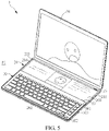
- FIG. 5 is a schematic diagram of the portable electronic device as shown in FIG. 1 in the second usage mode.
- a chat room interface such as chat windows
- a chat window can be used for transmitting messages, such that the user can interact with other users.
- a common notebook computer displays a game interface and a chat window on the same display panel, and thus needs to switch the game interface and the chat window frequently, resulting in inconvenience in use.
- the keyboard 30 can be moved to the second position P2 (i.e., the processing module 24 executes the second usage mode) so as to display the game interface on the first display panel 10 and display the chat window on the second display panel 20, so that the user does not need to switch the game interface and the chat window during operation.
- the keyboard 30 of the present example can be coupled with the second display panel 20 in a wireless mode.
- an input signal from the keyboard 30 can be transmitted in a Bluetooth mode.
- the processing module 24 can receive a connection signal to execute the first usage mode, the processing module 24 also can control a power supply module (not shown in figures) to supply power to the keyboard 30, and the power is transmitted by the first connector 26 and the second connector 33.
- the portable electronic device of the present example can also have a third usage mode, as shown in FIG. 6.
- FIG. 6 is a schematic diagram of the portable electronic device as shown in FIG. 1 in the third usage mode.
- a user can directly remove and use the keyboard 30, and the first display panel 10 and the second display panel 20 can be used for displaying simultaneously.
- the first display panel 10 and the second display panel 20 can be directly used as a common dual-screen display device, and the first display panel 10 and the second display panel 20 can be erected to serve as a usage mode for reading.
- FIG. 7 is an exploded diagram of a second display panel and a keyboard according to a second example of the present disclosure which is not part of the present invention and the present example refers to FIG. 7 .
- a second display panel 20a comprises a first positioning magnet 21a, a second positioning magnet 22a, and a guide magnet 23a
- a keyboard 30a comprises a third positioning magnet 31a and a magnetic element 32a.
- the difference between the present example and the first example is the numbers and arrangement positions of the first positioning magnet 21a, the second positioning magnet 22a, the guide magnet 23a, the magnetic induction module 25a, the third positioning magnet 31a, and the magnetic element 32a.
- other elements can directly refer to the first example and use the same reference numerals, and the same reference numerals represent the elements having the same functions.
- the first positioning magnet 21a is positioned on the first side edge 201
- the second positioning magnet 22a is positioned between the first side edge 201 and the second side edge 202
- the distance S between the second positioning magnet 22a and the first positioning magnet 21a is equal to the moving distance M of the keyboard 30a, which is approximately equal to the width of the keyboard 30a.
- the moving distance M as shown in FIG. 7 is marked on the second display panel 20a
- the moving distance M is marked with reference to the sixth side edge 302 of the keyboard 30a.
- the magnetic induction module 25a is arranged adjacent to the second positioning magnet 22a and thus is positioned between the first side edge 201 and the second side edge 202.
- the third positioning magnet 31a is positioned on the fifth side edge 301.
- the second display panel 20a is only provided with one guide magnet 23a arranged on the third side edge 203.
- the keyboard 30a is provided with one magnetic element 32a arranged on the fifth side edge 301.
- the keyboard 30a When the keyboard 30a is in the first position P1, the first positioning magnet 21a positioned on the first side edge 201 and the third positioning magnet 31a positioned on the fifth side edge 301 can be magnetically attracted to each other, therefore, the keyboard 30a is fixed in the first position P1.
- the magnetic element 32a of the present example is also strip-shaped, and the long axis direction of the magnetic element 32a is parallel to the moving direction D of the keyboard 30a, so the keyboard 30a can move from the first position P1 to the second position P2 along the moving direction D by the magnetic attraction force between the magnetic element 32a and the guide magnet 23a.
- the distance S between the second positioning magnet 22a and the first positioning magnet 21a is equal to the moving distance M of the keyboard 30a
- the third positioning magnet 3 1a moves to the position of the second positioning magnet 22a
- the second positioning magnet 22a and the third positioning magnet 31a can be magnetically attracted to each other, and then, the keyboard 30a is fixed in the second position P2.
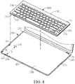
- FIG. 8 is an exploded diagram of a second display panel and a keyboard according to a third example of the present disclosure which is not part of the present invention and the present example refers to FIG. 8 .
- the numbers of first positioning magnet 21b, second positioning magnet 22b, and third positioning magnet 31b of the present example are the same as those of the second example, but the arrangement positions are different.
- other elements can directly refer to the first or second example and use the same reference numerals, and the same reference numerals represent the elements having the same functions.
- the second positioning magnet 22b is positioned on the second side edge 202
- the first positioning magnet 21b is positioned between the first side edge 201 and the second side edge 202
- the distance S between the first positioning magnet 21b and the second positioning magnet 22b is equal to the moving distance M of a keyboard 30b.
- the moving distance M as shown in FIG. 8 is marked on the second display panel 20b
- the moving distance M is marked with reference to the sixth side edge 302 of the keyboard 30b.
- the third positioning magnet 31b of the present example is positioned on the sixth side edge 302 of the keyboard 30b.
- a magnetic induction module 25b is arranged adjacent to the second positioning magnet 22b and is arranged on the second side edge 202.
- the keyboard 30b When the keyboard 30b is in the first position P1, the third positioning magnet 31b positioned on the sixth side edge 302 and the first positioning magnet 21b can be magnetically attracted to each other, therefore, the keyboard 30b is fixed in the first position P1.
- the second positioning magnet 22b positioned on the second side edge 202 and the third positioning magnet 31b can be magnetically attracted to each other, therefore, the keyboard 30b is fixed in the second position P2.
- the arrangement relationship and the connection relationship between the guide magnet 23a and the magnetic element 32a of the present example are the same as those of the second example, so the reference numerals are used.
- FIG. 9 is an exploded diagram of a second display panel and a keyboard according to an embodiment of the present disclosure and the present embodiment refers to FIG. 9 .
- the difference between the present embodiment and the first embodiment is that a second display panel 20c further comprises at least one slide rail 27c, and a guide magnet 23c can move in the slide rail 27c.
- a guide magnet 23c can move in the slide rail 27c.
- other elements can directly refer to the first embodiment and use the same reference numerals, and the same reference numerals represent the elements having the same functions.
- the slide rail 27c of the present embodiment is arranged below the display screen 200 of the second display panel 20c, and the slide rail 27c is parallel to the moving direction D.
- slide rails 27c are arranged bilaterally, so the second display panel 20c is provided with two slide rails 27c which are respectively positioned on the third side edge 203 and the fourth side edge 204. Furthermore, guide magnets 23c are arranged in the slide rails 27c and can move in the slide rails 27c.
- the keyboard 30 of the present embodiment is the same as that of the first embodiment and thus uses the same reference numerals, and the keyboard 30 of the present embodiment is provided with two magnetic elements 32 which are respectively positioned on the seventh side edge 303 and the eighth side edge 304. When the keyboard 30 is arranged on the second display panel 20c, the guide magnets 23c and the magnetic elements 32 can be magnetically attracted to each other.
- the magnetic elements 32 drive the guide magnets 23c to move along the slide rails 27c.
- the slide rail 27c is strip-shaped, and the long axis of the slide rail 27c is parallel to the moving direction D, so the keyboard 30 can be guided to move between the first position P1 and the second position P2 along the moving direction D.
- the slide rail 27c can also be arranged unilaterally and is positioned on the third side edge 203 or the fourth side edge 204.
- the magnetic element 32 is positioned on the seventh side edge 303 or the eighth side edge 304, and the effect of guiding the keyboard 30 to move can also be achieved.
- the portable electronic device of the present disclosure is provided with the first display panel, the second display panel, and the keyboard, and the keyboard is detachably arranged on the second display panel, so that a user can directly operate the keyboard to achieve an effect of inputting with a physical keyboard.
- the second display panel comprises guide magnets
- the keyboard comprises magnetic elements, so that the keyboard can be controlled by the guide magnets and the magnetic elements to slide on the display screen.
- the keyboard in different positions can be used in different usage modes, so that the portable electronic device (dual-screen notebook computer) has more diverse usage modes.
Description
- The present disclosure relates to a portable electronic device, and particularly relates to a portable electronic device with two touch display panels.
- With the development of the science and technology, the touch technology is becoming more mature and the processor performance is improved, so that portable electronic devices such as notebook computers and tablet computers can perform more functions. Operators who design or manufacture portable electronic devices need to provide various types of portable electronic devices according to requirements of different users.
- In the case of notebook computers, a notebook computer composed of two touch display panels is further provided on the market, and the display surfaces of the two touch display panels are respectively positioned on the B surface and the C surface of the notebook computer. Generally, this type of portable electronic device is called a dual-screen notebook computer, and a user can use the two touch display panels to achieve an interactive effect. This type of notebook computer does not have a physical keyboard, and touch input is directly performed on the display surfaces of two touch display panels or the display surface of one touch display panel. For example, for some users who have drawing requirements, the display surface of one touch display panel can be used as a drawing board. In some usage modes, a virtual keyboard can also be displayed on the touch display panel of the C surface, but a user still clicks the virtual keyboard of the C surface by touch.
- However, for a user who is accustomed to using a physical keyboard, the physical keyboard only can be electrically connected additionally. In other words, in addition to carrying a dual-screen notebook computer, the user needs to carry the physical keyboard, which is quite inconvenient for the user and is necessary for improvement.
-
US 2004/108968 A1 discloses a user terminal combining touch-screen and keyboard functionality and also combining laptop and flat-pad layouts. The flat-pad layout can be locked into place using sliding pieces. The terminal comprises a base including a keyboard, a first display screen attached to the base along a primary fold line, a second display screen included in the base and located between the keyboard and the primary fold line, and at least one sliding piece for fixing the second display screen in a substantially flat configuration with the first display screen and/or with another part of the base. The first display screen, the second display screen, and the keyboard have substantially the same width, in order to fully utilize the width of the entire user terminal. -
US 2014/211393 A1 discloses a detachable rotary extended keyboard plate, which includes a sleeve member, and the sleeve member includes a bottom plate having one end formed with an engaging sheet, after the engaging sheet is rotated, the additional space formed on the bottom plate allows a portable electronic device to stand in a multi-angle manner; a support sheet; a combination sheet; at least a first fasten device disposed on the engaging sheet or the combination sheet; and at least a second fasten device disposed on the keyboard and corresponding to the location where the first fasten device is disposed, the second fasten device is able to be combined with the first fasten device for enabling the keyboard to be fastened on the engaging sheet. -
US 2014/204519 A1 discloses an electronic device including a base and a keyboard. The base includes a working surface and defines a receiving space. The keyboard includes a top side and a bottom side opposite to the top side. A plurality of key is mounted on the top side. A function module is mounted on the bottom side. -
US 2016/349909 A1 discloses a portable electronic device including a first body and a second body. The second body includes a processing unit, and a first touch panel, a second touch panel, a keyboard and at least one detecting module electrically connected to the processing unit, respectively. The keyboard is slidably disposed above the second touch panel, and the detecting module is adapted to detect a position of the keyboard. - In view of the above problem, the present disclosure is directed to a portable electronic device, comprising a first display panel, a second display panel, and a keyboard. Guide magnets are arranged on the second display panel and magnetic elements are arranged on the keyboard, so that the keyboard can be arranged on the second display panel and can slide among different positions to solve the problem that a conventional dual-screen notebook computer cannot implement input through a physical keyboard.
- In order to achieve the above purpose, the present disclosure provides a portable electronic device, comprising a first display panel, a second display panel, and a keyboard. The second display panel is pivotally connected to the first display panel. The second display panel comprises a display screen, at least one guide magnet, and at least one slide rail arranged below the display screen of the second display panel. The at least one guide magnet is arranged below the display screen. The keyboard is detachably arranged above the display screen of the second display panel. The keyboard comprises at least one magnetic element. The keyboard can be controlled to move relative to the display screen along a moving direction by means of the magnetic attraction force between the at least one magnetic element and the at least one guide magnet, wherein the moving direction is perpendicular to a side edge of the second display panel pivotally connected to the first display panel. The at least one slide rail is parallel to the moving direction, and the at least one guide magnet is respectively arranged in the at least one slide rail. The at least one magnetic element drives the at least one guide magnet to move along the at least one slide rails.
- Based on the above, the portable electronic device of the present disclosure is provided with the first display panel, the second display panel, and the keyboard, and the keyboard is detachably arranged on the second display panel, so that a user can directly operate the keyboard to achieve an effect of inputting with a physical keyboard. Furthermore, the second display panel comprises guide magnets, and the keyboard comprises magnetic elements, so that the keyboard can be controlled to slide on the display screen with the guide magnets and the magnetic elements.
- Furthermore, the keyboard in different positions can be used with different usage modes, so that the portable electronic device (dual-screen notebook computer) has more diverse usage modes.
-
-
FIG. 1 is a schematic diagram of a portable electronic device according to a first example of the present disclosure which is not part of the present invention. -
FIG. 2 is an exploded diagram of a second display panel and a keyboard as shown inFIG. 1 . -
FIG. 3A to FIG. 3C are actuation schematic diagrams of the keyboard as shown inFIG. 1 moving on the second display panel. -
FIG. 4 is a block diagram of the second display panel and the keyboard as shown inFIG. 1 . -
FIG. 5 is a schematic diagram of the portable electronic device as shown inFIG. 1 in a second usage mode. -
FIG. 6 is a schematic diagram of the portable electronic device as shown inFIG. 1 in a third usage mode. -
FIG. 7 is an exploded diagram of a second display panel and a keyboard according to a second example of the present disclosure which is not part of the present invention. -
FIG. 8 is an exploded diagram of a second display panel and a keyboard according to a third example of the present disclosure which is not part of the present invention. -
FIG. 9 is an exploded diagram of a second display panel and a keyboard according to an embodiment of the present invention. - In order to more clearly understand the features, contents and advantages of the present disclosure and the effects thereof, the present disclosure will be described in detail below with reference to the accompanying drawings in the form of embodiment and examples.
-
FIG. 1 is a schematic diagram of a portable electronic device according to a first example of the present disclosure which is not part of the present invention,FIG. 2 is an exploded diagram of a second display panel and a keyboard as shown inFIG. 1 , and the present example refers toFIG. 1 andFIG. 2 . Firstly, the portableelectronic device 1 of the present example is illustrated by taking a dual-screen notebook computer as an example. That is, the portableelectronic device 1 is composed of two touch display panels which are respectively afirst display panel 10 and asecond display panel 20 herein. In other words, the portableelectronic device 1 of the present example comprises afirst display panel 10 and asecond display panel 20, and thesecond display panel 20 is pivotally connected to thefirst display panel 10 and can be electrically connected to thefirst display panel 10 in a wired or wireless mode, so that signal and data transmission can be performed between thefirst display panel 10 and thesecond display panel 20. - In the present example, one side edge of the
second display panel 20 is pivotally connected to thefirst display panel 10, in which thefirst display panel 10 can be used as A and B elements of the portableelectronic device 1, and thesecond display panel 20 can be used as C and D elements of the portableelectronic device 1. In order to clearly explain the arrangement positions of all elements, four side edges of thesecond display panel 20 are respectively named as afirst side edge 201, asecond side edge 202, athird side edge 203, and afourth side edge 204, in which thefirst side edge 201 of thesecond display panel 20 is pivotally connected to the side edge of thefirst display panel 10, thesecond side edge 202 is opposite to thefirst side edge 201, thethird side edge 203 and thefourth side edge 204 are positioned at two adjacent sides of thefirst side edge 201, and thethird side edge 203 is opposite to thefourth side edge 204. - Furthermore, the portable
electronic device 1 further comprises akeyboard 30, and thekeyboard 30 is detachably arranged above thedisplay screen 200 of thesecond display panel 20, namely the C surface of the portableelectronic device 1. Similarly, in order to clearly explain the arrangement positions of all elements, four side edges of thekeyboard 30 are respectively named as afifth side edge 301, asixth side edge 302, aseventh side edge 303, and aneighth side edge 304, in which thesixth side edge 302 is opposite to thefifth side edge 301, and theeighth side edge 304 is opposite to theseventh side edge 303. When thekeyboard 30 is placed above thedisplay screen 200, thefifth side edge 301, thesixth side edge 302, theseventh side edge 303, and theeighth side edge 304 are sequentially corresponding to thefirst side edge 201, thesecond side edge 202, thethird side edge 203, and thefourth side edge 204. - References are made to
FIG. 3A to FIG. 3C. FIG. 3A to FIG. 3C are actuation schematic diagrams of the keyboard as shown inFIG. 1 moving on the second display panel. As shown inFIG. 3A to FIG. 3C , thekeyboard 30 can slide on thedisplay screen 200 along a moving direction D. For example, thekeyboard 30 can slide between a first position P1 (as shown inFIG. 3A ) and a second position P2 (as shown inFIG. 3C ). In the present example, the moving direction D is perpendicular to thefirst side edge 201 of thesecond display panel 20 pivotally connected to thefirst display panel 10. As shown inFIG. 3A , the first position P1 of the present example is a position in which thekeyboard 30 is close to thefirst display panel 10. As shown inFIG. 3C , the second position P2 is a position in which thekeyboard 30 is away from thefirst display panel 10. - In some examples, as shown in
FIG. 2 , thesecond display panel 20 comprises at least onefirst positioning magnet 21 and at least onesecond positioning magnet 22, and correspondingly, thekeyboard 30 comprises at least onethird positioning magnet 31 in order to position thekeyboard 30 in the first position P1 or the second position P2. - Furthermore, the
second display panel 20 further comprises at least oneguide magnet 23, thekeyboard 30 further comprises at least onemagnetic element 32, and thekeyboard 30 can be controlled to slide along the moving direction D between the first position P1 and the second position P2 with a smaller magnetic attraction force between theguide magnet 23 and themagnetic element 32. It should be noted that the smaller magnetic attraction force herein means that the magnetic attraction force between theguide magnet 23 and themagnetic element 32 is smaller than the magnetic attraction force between thefirst positioning magnet 21, thesecond positioning magnet 22, and thethird positioning magnet 31, in which thefirst positioning magnet 21, thesecond positioning magnet 22, thethird positioning magnet 31, and theguide magnet 23 are all magnets, but the disclosure is not limited thereto. The arrangement relationship between each magnet and themagnetic element 32 is described below by taking the first example as an example. - Referring to
FIG. 2 , in the present example, thesecond display panel 20 comprises twofirst positioning magnets 21 and twosecond positioning magnets 22, and thefirst positioning magnets 21 and thesecond positioning magnets 22 are arranged below thedisplay screen 200 of thesecond display panel 20, in which the twofirst positioning magnets 21 are spaced apart on thefirst side edge 201, and the twosecond positioning magnets 22 are spaced apart on thesecond side edge 202. Correspondingly, thekeyboard 30 is provided with fourthird positioning magnets 31, in which twothird positioning magnets 31 are positioned on thefifth side edge 301, and the other twothird positioning magnets 31 are positioned on thesixth side edge 302 so as to correspond to the positions of thefirst positioning magnets 21 and thesecond positioning magnets 22 of thesecond display panel 20. Preferably, thethird positioning magnets 31 are arranged at the bottom of thekeyboard 30 so as to be close to thesecond display panel 20. In the present disclosure, whether thethird positioning magnets 31 are arranged on the inner surface or the outer surface of thekeyboard 30 is not limited. Preferably, thethird positioning magnets 31 can be arranged on the inner surface of thekeyboard 30, namely inside thekeyboard 30, so as to keep the integrality of the appearance of thekeyboard 30. - Furthermore, the
second display panel 20 is provided with fourguide magnets 23, and theguide magnets 23 are also arranged below thedisplay screen 200 of thesecond display panel 20, in which twoguide magnets 23 are spaced apart on thethird side edge 203, and the other twoguide magnets 23 are spaced apart on thefourth side edge 204. Correspondingly, thekeyboard 30 is provided with twomagnetic elements 32 positioned on theseventh side edge 303 or theeighth side edge 304. Themagnetic elements 32 are arranged at the bottom of thekeyboard 30 and can be positioned on the inner surface or the outer surface of thekeyboard 30. Themagnetic elements 32 of the present example are positioned on the inner surface of thekeyboard 30 in order to keep the integrality of the appearance of thekeyboard 30. Themagnetic elements 32 of the present example are strip-shaped, and the long axis direction of themagnetic elements 32 is parallel to the moving direction D of thekeyboard 30 so as to guide thekeyboard 30 to move along the moving direction D. - References are made to
FIG. 2 andFIG. 3A , when thekeyboard 30 is in the first position P1, thefifth side edge 301 of thekeyboard 30 is close to thefirst side edge 201 of thesecond display panel 20. Thethird positioning magnet 31 positioned on thefifth side edge 301 and thefirst positioning magnet 21 positioned on thefirst side edge 201 can be magnetically attracted to each other, therefore, thekeyboard 30 is fixed in the first position P1. At this time, theguide magnet 23 close to thefirst side edge 201 and themagnetic element 32 are also magnetically attracted to each other. Subsequently, a user can apply a force to thekeyboard 30 to push thekeyboard 30 to move towards the direction of thesecond side edge 202. When the force applied by the user is greater than the magnetic attraction force between thefirst positioning magnet 21 and thethird positioning magnet 31, thekeyboard 30 can be pushed to move towards the direction of thesecond side edge 202, and theguide magnet 23 close to thesecond side edge 202 and themagnetic element 32 can be magnetically attracted to each other so as to guide thekeyboard 30 to continue moving towards the direction of thesecond side edge 202, as shown inFIG. 3B . When thekeyboard 30 moves to the second position P2, thesixth side edge 302 of thekeyboard 30 is close to thesecond side edge 202 of thesecond display panel 20. Thethird positioning magnet 31 positioned on thesixth side edge 302 and thesecond positioning magnet 22 positioned on thesecond side edge 202 are magnetically attracted to each other, therefore, thekeyboard 30 is fixed in the second position P2, as shown inFIG. 3C . - Therefore, the
first positioning magnet 21 and thesecond positioning magnet 22 of thesecond display panel 20 are respectively used to position thekeyboard 30 in the first position P1 and the second position P2, and theguide magnet 23 is used to limit the moving region of thekeyboard 30 and can guide thekeyboard 30 to move from the first position P1 to the second position P2. As shown inFIG. 2 , in the present example, both thethird side edge 203 and thefourth side edge 204 of thesecond display panel 20 are provided withguide magnets 23, and theseventh side edge 303 and theeighth side edge 304 of thekeyboard 30 are correspondingly provided withmagnetic elements 32. In other examples, theguide magnets 23 and themagnetic elements 32 can also be arranged on only one side edge of thesecond display panel 20 and thekeyboard 30. For example, thesecond display panel 20 can also be provided with twoguide magnets 23 which are spaced apart on thethird side edge 203 or thefourth side edge 204. Correspondingly, thekeyboard 30 is provided with onemagnetic element 32 which is arranged on theseventh side edge 303 or theeighth side edge 304 according to the position of theguide magnet 23. Furthermore, the present disclosure does not limit the numbers of theguide magnets 23 and themagnetic elements 32, any other number ofguide magnets 23 andmagnetic elements 32 can be arranged. - Preferably, the upper surface of the
display screen 200 of thesecond display panel 20 is a groove, and thekeyboard 30 can be contained in the groove to limit the moving region of thekeyboard 30 so as to prevent thekeyboard 30 from exceeding thethird side edge 203 or thefourth side edge 204 of thesecond display panel 20 when moving. -
FIG. 4 is a block diagram of the second display panel and the keyboard as shown inFIG. 1 , and references are made toFIG. 2 andFIG. 4 . Preferably, thesecond display panel 20 can also execute different usage modes according to different positions (first position P1 or second position P2) of thekeyboard 30. Specifically, thesecond display panel 20 of the present example further comprises aprocessing module 24, amagnetic induction module 25, and afirst connector 26, and themagnetic induction module 25 and thefirst connector 26 are electrically connected to theprocessing module 24 respectively, in which themagnetic induction module 25 is arranged adjacent to thesecond positioning magnet 22, and thefirst connector 26 is arranged on thefirst side edge 201. Correspondingly, thekeyboard 30 further comprises asecond connector 33 arranged on thefifth side edge 301. - When the
keyboard 30 is in the first position P1, thefirst connector 26 is electrically connected to thesecond connector 33, and thefirst connector 26 can transmit a connection signal to theprocessing module 24. After theprocessing module 24 receives the connection signal, a first usage mode can be executed, as shown inFIG. 1 . In the present example, theprocessing module 24 executes the first usage mode, including controlling thesecond display panel 20 to display atouch panel 205 on a block close to thesecond side edge 202 for a user to operate a cursor position. In other words, the first usage mode is an operation mode of a common notebook computer, the B surface (first display panel 10) is used as a display screen, and the C surface is provided with a physical keyboard (keyboard 30) and thetouch panel 205. - When the
keyboard 30 is in the second position P2, thethird positioning magnet 31 and thesecond positioning magnet 22 are magnetically attracted to each other to generate a magnetic force change; when themagnetic induction module 25 arranged adjacent to thesecond positioning magnet 22 detects the magnetic force change, an induction signal can be transmitted to theprocessing module 24; and when theprocessing module 24 receives the induction signal from themagnetic induction module 25, a second usage mode can be executed according to the induction signal. In the present example, theprocessing module 24 executes the second usage mode, such as controlling thesecond display panel 20 to display a chat window on a block close to thefirst side edge 201, as shown inFIG. 5. FIG. 5 is a schematic diagram of the portable electronic device as shown inFIG. 1 in the second usage mode. At present, there are many video playing interfaces, game interfaces or live interfaces having a chat room interface (such as chat windows), and when a user is playing the game, a chat window can be used for transmitting messages, such that the user can interact with other users. However, a common notebook computer displays a game interface and a chat window on the same display panel, and thus needs to switch the game interface and the chat window frequently, resulting in inconvenience in use. By comparison, in the present example, thekeyboard 30 can be moved to the second position P2 (i.e., theprocessing module 24 executes the second usage mode) so as to display the game interface on thefirst display panel 10 and display the chat window on thesecond display panel 20, so that the user does not need to switch the game interface and the chat window during operation. - Furthermore, the
keyboard 30 of the present example can be coupled with thesecond display panel 20 in a wireless mode. For example, an input signal from thekeyboard 30 can be transmitted in a Bluetooth mode. When thekeyboard 30 is in the first position P1, thefirst connector 26 can be electrically connected to thesecond connector 33, theprocessing module 24 can receive a connection signal to execute the first usage mode, theprocessing module 24 also can control a power supply module (not shown in figures) to supply power to thekeyboard 30, and the power is transmitted by thefirst connector 26 and thesecond connector 33. - The portable electronic device of the present example can also have a third usage mode, as shown in
FIG. 6. FIG. 6 is a schematic diagram of the portable electronic device as shown inFIG. 1 in the third usage mode. In the third usage mode, a user can directly remove and use thekeyboard 30, and thefirst display panel 10 and thesecond display panel 20 can be used for displaying simultaneously. Furthermore, thefirst display panel 10 and thesecond display panel 20 can be directly used as a common dual-screen display device, and thefirst display panel 10 and thesecond display panel 20 can be erected to serve as a usage mode for reading. -
FIG. 7 is an exploded diagram of a second display panel and a keyboard according to a second example of the present disclosure which is not part of the present invention and the present example refers toFIG. 7 . In the present example, a second display panel 20a comprises afirst positioning magnet 21a, asecond positioning magnet 22a, and aguide magnet 23a, and akeyboard 30a comprises athird positioning magnet 31a and amagnetic element 32a. The difference between the present example and the first example is the numbers and arrangement positions of thefirst positioning magnet 21a, thesecond positioning magnet 22a, theguide magnet 23a, themagnetic induction module 25a, thethird positioning magnet 31a, and themagnetic element 32a. In order to simplify the description, other elements can directly refer to the first example and use the same reference numerals, and the same reference numerals represent the elements having the same functions. - In the present example, the
first positioning magnet 21a is positioned on thefirst side edge 201, thesecond positioning magnet 22a is positioned between thefirst side edge 201 and thesecond side edge 202, and the distance S between thesecond positioning magnet 22a and thefirst positioning magnet 21a is equal to the moving distance M of thekeyboard 30a, which is approximately equal to the width of thekeyboard 30a. It should be noted that the moving distance M as shown inFIG. 7 is marked on the second display panel 20a, and the moving distance M is marked with reference to thesixth side edge 302 of thekeyboard 30a. Furthermore, themagnetic induction module 25a is arranged adjacent to thesecond positioning magnet 22a and thus is positioned between thefirst side edge 201 and thesecond side edge 202. Thethird positioning magnet 31a is positioned on thefifth side edge 301. The second display panel 20a is only provided with oneguide magnet 23a arranged on thethird side edge 203. Correspondingly, thekeyboard 30a is provided with onemagnetic element 32a arranged on thefifth side edge 301. - When the
keyboard 30a is in the first position P1, thefirst positioning magnet 21a positioned on thefirst side edge 201 and thethird positioning magnet 31a positioned on thefifth side edge 301 can be magnetically attracted to each other, therefore, thekeyboard 30a is fixed in the first position P1. Themagnetic element 32a of the present example is also strip-shaped, and the long axis direction of themagnetic element 32a is parallel to the moving direction D of thekeyboard 30a, so thekeyboard 30a can move from the first position P1 to the second position P2 along the moving direction D by the magnetic attraction force between themagnetic element 32a and theguide magnet 23a. Furthermore, because the distance S between thesecond positioning magnet 22a and thefirst positioning magnet 21a is equal to the moving distance M of thekeyboard 30a, when thekeyboard 30a moves to the second position P2, the third positioning magnet 3 1a moves to the position of thesecond positioning magnet 22a, thesecond positioning magnet 22a and thethird positioning magnet 31a can be magnetically attracted to each other, and then, thekeyboard 30a is fixed in the second position P2. -
FIG. 8 is an exploded diagram of a second display panel and a keyboard according to a third example of the present disclosure which is not part of the present invention and the present example refers toFIG. 8 . The numbers offirst positioning magnet 21b,second positioning magnet 22b, andthird positioning magnet 31b of the present example are the same as those of the second example, but the arrangement positions are different. In order to simplify the description, other elements can directly refer to the first or second example and use the same reference numerals, and the same reference numerals represent the elements having the same functions. In the present example, thesecond positioning magnet 22b is positioned on thesecond side edge 202, thefirst positioning magnet 21b is positioned between thefirst side edge 201 and thesecond side edge 202, and the distance S between thefirst positioning magnet 21b and thesecond positioning magnet 22b is equal to the moving distance M of akeyboard 30b. Similarly, the moving distance M as shown inFIG. 8 is marked on the second display panel 20b, and the moving distance M is marked with reference to thesixth side edge 302 of thekeyboard 30b. Thethird positioning magnet 31b of the present example is positioned on thesixth side edge 302 of thekeyboard 30b. A magnetic induction module 25b is arranged adjacent to thesecond positioning magnet 22b and is arranged on thesecond side edge 202. - When the
keyboard 30b is in the first position P1, thethird positioning magnet 31b positioned on thesixth side edge 302 and thefirst positioning magnet 21b can be magnetically attracted to each other, therefore, thekeyboard 30b is fixed in the first position P1. When thekeyboard 30b moves to the second position P2, thesecond positioning magnet 22b positioned on thesecond side edge 202 and thethird positioning magnet 31b can be magnetically attracted to each other, therefore, thekeyboard 30b is fixed in the second position P2. The arrangement relationship and the connection relationship between theguide magnet 23a and themagnetic element 32a of the present example are the same as those of the second example, so the reference numerals are used. -
FIG. 9 is an exploded diagram of a second display panel and a keyboard according to an embodiment of the present disclosure and the present embodiment refers toFIG. 9 . The difference between the present embodiment and the first embodiment is that asecond display panel 20c further comprises at least oneslide rail 27c, and aguide magnet 23c can move in theslide rail 27c. In order to simplify the description, other elements can directly refer to the first embodiment and use the same reference numerals, and the same reference numerals represent the elements having the same functions. Theslide rail 27c of the present embodiment is arranged below thedisplay screen 200 of thesecond display panel 20c, and theslide rail 27c is parallel to the moving direction D. Specifically, in the present embodiment, slide rails 27c are arranged bilaterally, so thesecond display panel 20c is provided with twoslide rails 27c which are respectively positioned on thethird side edge 203 and thefourth side edge 204. Furthermore, guidemagnets 23c are arranged in the slide rails 27c and can move in the slide rails 27c. Thekeyboard 30 of the present embodiment is the same as that of the first embodiment and thus uses the same reference numerals, and thekeyboard 30 of the present embodiment is provided with twomagnetic elements 32 which are respectively positioned on theseventh side edge 303 and theeighth side edge 304. When thekeyboard 30 is arranged on thesecond display panel 20c, theguide magnets 23c and themagnetic elements 32 can be magnetically attracted to each other. When thekeyboard 30 is moved, themagnetic elements 32 drive theguide magnets 23c to move along the slide rails 27c. Theslide rail 27c is strip-shaped, and the long axis of theslide rail 27c is parallel to the moving direction D, so thekeyboard 30 can be guided to move between the first position P1 and the second position P2 along the moving direction D. In other embodiments, theslide rail 27c can also be arranged unilaterally and is positioned on thethird side edge 203 or thefourth side edge 204. Correspondingly, themagnetic element 32 is positioned on theseventh side edge 303 or theeighth side edge 304, and the effect of guiding thekeyboard 30 to move can also be achieved. - In conclusion, the portable electronic device of the present disclosure is provided with the first display panel, the second display panel, and the keyboard, and the keyboard is detachably arranged on the second display panel, so that a user can directly operate the keyboard to achieve an effect of inputting with a physical keyboard. Furthermore, the second display panel comprises guide magnets, and the keyboard comprises magnetic elements, so that the keyboard can be controlled by the guide magnets and the magnetic elements to slide on the display screen.
- Furthermore, the keyboard in different positions (first position or second position) can be used in different usage modes, so that the portable electronic device (dual-screen notebook computer) has more diverse usage modes.
- The above embodiments are only used for explaining the technical idea and features of the present disclosure, and the objective of the present disclosure is to enable those skilled in the art to understand the contents of the present disclosure and to implement the present disclosure, but the scope of the present disclosure cannot be limited thereto.
Claims (11)
- A portable electronic device (1), comprising:a first display panel (10);a second display panel (20c), pivotally connected to the first display panel (10); the second display panel (20c) comprising:a display screen (200);at least one guide magnet (23c) arranged below the display screen (200); andat least one slide rail (27c) arranged below the display screen (200) of the second display panel (20c); anda keyboard, detachably arranged above the display screen (200) of the second display panel (20c) and the keyboard comprising:at least one magnetic element (32), wherein the keyboard can be controlled to move relative to the display screen (200) along a moving direction by means of the magnetic attraction force between the at least one magnetic element (32) and the at least one guide magnet (23c), and the moving direction is perpendicular to a side edge of the second display panel (20c) pivotally connected to the first display panel (10), wherein the at least one slide rail (27c) is parallel to the moving direction, and the at least one guide magnet (23c) is respectively arranged in the at least one slide rail (27c), whereinthe at least one magnetic element (32) is configured to drive the at least one guide magnet (23c) to move along the at least one slide rail (27c).
- The portable electronic device (1) according to claim 1, wherein the second display panel (20c) further comprises a first positioning magnet and a second positioning magnet being respectively arranged below the display screen (200) of the second display panel (20c); the keyboard further comprises a pair of third positioning magnets, each magnet of the pair of third positioning magnets corresponding respectively to either the first positioning magnet or the second positioning magnet; when the keyboard is in a first position on the display screen (200), the first positioning magnet and its corresponding third positioning magnet are magnetically attracted to each other; and when the keyboard is in a second position on the display screen (200), the second positioning magnet and its corresponding third positioning magnet are magnetically attracted to each other.
- The portable electronic device (1) according to claim 2, wherein the second display panel (20c) comprises a first side edge, a second side edge, a third side edge, and a fourth side edge; the second side edge is opposite to the first side edge, the third side edge is opposite to the fourth side edge, and the first side edge is pivotally connected to the first display panel (10); the keyboard comprises a fifth side edge, a sixth side edge, a seventh side edge, and an eighth side edge; the sixth side edge is opposite to the fifth side edge, and the eighth side edge is opposite to the seventh side edge; when the keyboard is in the first position, the fifth side edge is close to the first side edge; and when the keyboard is in the second position, the sixth side edge is close to the second side edge.
- The portable electronic device (1) according to claim 3, wherein the first positioning magnet is positioned on the first side edge, its corresponding third positioning magnet is positioned on the fifth side edge, and a distance between the second positioning magnet and the first positioning magnet is equal to a moving distance of the keyboard.
- The portable electronic device (1) according to any one of claims 3 to 4, wherein the second positioning magnet is positioned on the second side edge, its corresponding third positioning magnet is positioned on the sixth side edge, and a distance between the first positioning magnet and the second positioning magnet is equal to a moving distance of the keyboard.
- The portable electronic device (1) according to any one of claims 3 to 5, wherein the second display panel (20c) is provided with at least two guide magnets (23c) being spaced apart on the third side edge or the fourth side edge, and the magnetic element (32) is positioned on the seventh side edge or the eighth side edge.
- The portable electronic device (1) according to any one of claims 2 to 6, wherein the second display panel (20c) further comprises a processing module and a magnetic induction module, the magnetic induction module is electrically connected to the processing module, and the magnetic induction module is arranged adjacent to the second positioning magnet.
- The portable electronic device (1) according to claim 7, wherein the second display panel (20c) further comprises a first connector being electrically connected to the processing module; the keyboard further comprises a second connector; and when the keyboard is in the first position, the first connector is electrically connected to the second connector, and the processing module is configured to receive a connection signal and to execute a first usage mode.
- The portable electronic device (1) according to any one of claims 7 to 8, wherein when the keyboard is in the second position, the second positioning magnet and its corresponding third positioning magnet are magnetically attracted to each other, the processing module is configured to receive an induction signal from the magnetic induction module, and to execute a second usage mode.
- The portable electronic device (1) according to any one of claims 1 to 9, wherein an upper surface of the display screen (200) of the second display panel (20c) is a groove and the keyboard is contained in the groove.
- The portable electronic device (1) according to any one of claims 1 to 10, wherein both the first display panel (10) and the second display panel (20c) are touch display panels.
Applications Claiming Priority (1)
| Application Number | Priority Date | Filing Date | Title |
|---|---|---|---|
| TW107142514A TWI682267B (en) | 2018-11-28 | 2018-11-28 | Portable electrical device |
Publications (2)
| Publication Number | Publication Date |
|---|---|
| EP3661177A1 EP3661177A1 (en) | 2020-06-03 |
| EP3661177B1 true EP3661177B1 (en) | 2022-05-11 |
Family
ID=68296331
Family Applications (1)
| Application Number | Title | Priority Date | Filing Date |
|---|---|---|---|
| EP19204466.7A Active EP3661177B1 (en) | 2018-11-28 | 2019-10-22 | Portable electronic device |
Country Status (6)
| Country | Link |
|---|---|
| US (1) | US10768662B2 (en) |
| EP (1) | EP3661177B1 (en) |
| JP (1) | JP6807439B2 (en) |
| KR (1) | KR102222288B1 (en) |
| CN (1) | CN111240408B (en) |
| TW (1) | TWI682267B (en) |
Families Citing this family (14)
| Publication number | Priority date | Publication date | Assignee | Title |
|---|---|---|---|---|
| US10653026B2 (en) * | 2018-01-08 | 2020-05-12 | Intel Corporation | Coupling systems and methods for electronic devices |
| US11586296B2 (en) | 2020-01-28 | 2023-02-21 | Dell Products L.P. | Dynamic keyboard support at support and display surfaces |
| US10983570B1 (en) * | 2020-01-28 | 2021-04-20 | Dell Products L.P. | Keyboard charging from an information handling system |
| US10990204B1 (en) * | 2020-01-28 | 2021-04-27 | Dell Products L.P. | Virtual touchpad at keyboard location |
| US10983567B1 (en) * | 2020-01-28 | 2021-04-20 | Dell Products L.P. | Keyboard magnetic guard rails |
| US10989978B1 (en) | 2020-01-28 | 2021-04-27 | Dell Products L.P. | Selectively transparent and opaque keyboard bottom |
| US10929016B1 (en) * | 2020-01-28 | 2021-02-23 | Dell Products L.P. | Touch calibration at keyboard location |
| US20210011520A1 (en) * | 2020-09-25 | 2021-01-14 | Intel Corporation | Locking and position status detection scheme for an electronic device |
| KR102252766B1 (en) | 2020-12-09 | 2021-05-14 | 엘지디스플레이 주식회사 | Display device |
| KR102252777B1 (en) * | 2020-12-09 | 2021-05-14 | 엘지디스플레이 주식회사 | Display device |
| CN114967841B (en) * | 2021-02-25 | 2023-07-25 | 宏碁股份有限公司 | Portable electronic device |
| TWI769744B (en) * | 2021-03-19 | 2022-07-01 | 翰碩電子股份有限公司 | Dual-mode touch device and dual-mode touch method |
| CN114779884A (en) * | 2022-03-08 | 2022-07-22 | 华为技术有限公司 | Method and system for detaching electronic equipment and device |
| US20230418329A1 (en) * | 2022-06-25 | 2023-12-28 | Lenovo (Singapore) Pte. Ltd | Dock and Keyboard System |
Family Cites Families (15)
| Publication number | Priority date | Publication date | Assignee | Title |
|---|---|---|---|---|
| JPH10240409A (en) * | 1997-02-28 | 1998-09-11 | Toshiba Corp | Electronic equipment and keyboard device |
| US7221330B2 (en) * | 2002-12-09 | 2007-05-22 | Nokia Corporation | Folding terminal with slider to fix terminal in a flat unfolded configuration |
| US7127776B2 (en) * | 2003-06-04 | 2006-10-31 | Lg Electronics Inc. | Dual display type portable computer and control method for the same |
| KR100667981B1 (en) * | 2003-06-04 | 2007-01-15 | 엘지전자 주식회사 | A dual display type portable computer |
| JP2007241962A (en) * | 2006-03-03 | 2007-09-20 | Shigeru Taniguchi | Multiple-screen type notebook computer |
| TW201124824A (en) | 2010-01-14 | 2011-07-16 | Acer Inc | Notebook computer |
| CN201628891U (en) * | 2010-03-31 | 2010-11-10 | 联想(北京)有限公司 | Notebook computer |
| KR101824126B1 (en) * | 2010-05-14 | 2018-02-01 | 가부시키가이샤 한도오따이 에네루기 켄큐쇼 | Electronic apparatus and method for connecting electronic device |
| TWI519924B (en) * | 2012-08-10 | 2016-02-01 | 緯創資通股份有限公司 | Portable computer |
| CN103941807A (en) * | 2013-01-22 | 2014-07-23 | 天津富纳源创科技有限公司 | Electronic device |
| TW201430528A (en) * | 2013-01-30 | 2014-08-01 | Hon Hai Prec Ind Co Ltd | Electronic device |
| CN103970198A (en) * | 2013-01-31 | 2014-08-06 | 联想(北京)有限公司 | Electronic equipment |
| TWI607357B (en) * | 2015-06-01 | 2017-12-01 | 仁寶電腦工業股份有限公司 | Poratble electronic device and controlling method of touch panel thereof |
| TWI590029B (en) | 2016-04-11 | 2017-07-01 | 宏碁股份有限公司 | A portable electronic device |
| US20180210504A1 (en) * | 2017-01-23 | 2018-07-26 | George Moser | Laptop computer with multiple integrated displays |
-
2018
- 2018-11-28 TW TW107142514A patent/TWI682267B/en active
-
2019
- 2019-07-09 KR KR1020190082595A patent/KR102222288B1/en active IP Right Grant
- 2019-07-24 CN CN201910671550.9A patent/CN111240408B/en active Active
- 2019-08-09 JP JP2019148001A patent/JP6807439B2/en active Active
- 2019-09-24 US US16/581,634 patent/US10768662B2/en active Active
- 2019-10-22 EP EP19204466.7A patent/EP3661177B1/en active Active
Also Published As
| Publication number | Publication date |
|---|---|
| TWI682267B (en) | 2020-01-11 |
| CN111240408A (en) | 2020-06-05 |
| CN111240408B (en) | 2021-05-25 |
| KR20200064881A (en) | 2020-06-08 |
| US10768662B2 (en) | 2020-09-08 |
| KR102222288B1 (en) | 2021-03-05 |
| US20200166964A1 (en) | 2020-05-28 |
| EP3661177A1 (en) | 2020-06-03 |
| JP2020087431A (en) | 2020-06-04 |
| TW202020610A (en) | 2020-06-01 |
| JP6807439B2 (en) | 2021-01-06 |
Similar Documents
| Publication | Publication Date | Title |
|---|---|---|
| EP3661177B1 (en) | Portable electronic device | |
| US8405978B2 (en) | Electronic device | |
| JP5745097B2 (en) | Cover attachment with flexible display | |
| CN109313464B (en) | Convertible dual-screen laptop computer | |
| JP2013161255A (en) | Information terminal device and information processing method | |
| CN103558981A (en) | Portable computer | |
| JP2013089257A (en) | Portable electronic equipment | |
| WO2013114503A1 (en) | Information terminal device | |
| US20140327615A1 (en) | Display device and input control method | |
| US20120218732A1 (en) | Electronic device | |
| US9268359B2 (en) | Tablet apparatus | |
| CN102012724B (en) | Terminal device and touch screen | |
| CN103037253B (en) | Remote control system and method for remotely controlling | |
| US9172778B2 (en) | Portable terminal device and state switching structure of portable terminal device | |
| TW201314461A (en) | Integrated expansion device | |
| US20130314348A1 (en) | Electronic device | |
| US6823222B2 (en) | Portable processor-based system | |
| US8482528B2 (en) | Ultra mobile personal computer | |
| US20120218691A1 (en) | Electronic device | |
| KR101241766B1 (en) | Wrinkles Phone Having Display Apparatus of Many Folds and Method thereof | |
| US8441446B2 (en) | Wireless input device integrable with mobile device | |
| US20140145958A1 (en) | Tablet computer assembly, accessory thereof, and tablet computer input method | |
| TW201621558A (en) | Input device | |
| JP5681013B2 (en) | Electronic device and control method thereof | |
| CN210091026U (en) | Portable electronic device |
Legal Events
| Date | Code | Title | Description |
|---|---|---|---|
| PUAI | Public reference made under article 153(3) epc to a published international application that has entered the european phase |
Free format text: ORIGINAL CODE: 0009012 |
|
| STAA | Information on the status of an ep patent application or granted ep patent |
Free format text: STATUS: THE APPLICATION HAS BEEN PUBLISHED |
|
| AK | Designated contracting states |
Kind code of ref document: A1 Designated state(s): AL AT BE BG CH CY CZ DE DK EE ES FI FR GB GR HR HU IE IS IT LI LT LU LV MC MK MT NL NO PL PT RO RS SE SI SK SM TR |
|
| AX | Request for extension of the european patent |
Extension state: BA ME |
|
| STAA | Information on the status of an ep patent application or granted ep patent |
Free format text: STATUS: REQUEST FOR EXAMINATION WAS MADE |
|
| 17P | Request for examination filed |
Effective date: 20201029 |
|
| RBV | Designated contracting states (corrected) |
Designated state(s): AL AT BE BG CH CY CZ DE DK EE ES FI FR GB GR HR HU IE IS IT LI LT LU LV MC MK MT NL NO PL PT RO RS SE SI SK SM TR |
|
| GRAP | Despatch of communication of intention to grant a patent |
Free format text: ORIGINAL CODE: EPIDOSNIGR1 |
|
| STAA | Information on the status of an ep patent application or granted ep patent |
Free format text: STATUS: GRANT OF PATENT IS INTENDED |
|
| INTG | Intention to grant announced |
Effective date: 20220111 |
|
| RAP3 | Party data changed (applicant data changed or rights of an application transferred) |
Owner name: PEGATRON CORPORATION |
|
| GRAS | Grant fee paid |
Free format text: ORIGINAL CODE: EPIDOSNIGR3 |
|
| GRAA | (expected) grant |
Free format text: ORIGINAL CODE: 0009210 |
|
| STAA | Information on the status of an ep patent application or granted ep patent |
Free format text: STATUS: THE PATENT HAS BEEN GRANTED |
|
| AK | Designated contracting states |
Kind code of ref document: B1 Designated state(s): AL AT BE BG CH CY CZ DE DK EE ES FI FR GB GR HR HU IE IS IT LI LT LU LV MC MK MT NL NO PL PT RO RS SE SI SK SM TR |
|
| REG | Reference to a national code |
Ref country code: GB Ref legal event code: FG4D |
|
| REG | Reference to a national code |
Ref country code: CH Ref legal event code: EP |
|
| REG | Reference to a national code |
Ref country code: AT Ref legal event code: REF Ref document number: 1492476 Country of ref document: AT Kind code of ref document: T Effective date: 20220515 |
|
| REG | Reference to a national code |
Ref country code: DE Ref legal event code: R096 Ref document number: 602019014798 Country of ref document: DE |
|
| REG | Reference to a national code |
Ref country code: IE Ref legal event code: FG4D |
|
| REG | Reference to a national code |
Ref country code: LT Ref legal event code: MG9D |
|
| REG | Reference to a national code |
Ref country code: NL Ref legal event code: MP Effective date: 20220511 |
|
| REG | Reference to a national code |
Ref country code: AT Ref legal event code: MK05 Ref document number: 1492476 Country of ref document: AT Kind code of ref document: T Effective date: 20220511 |
|
| PG25 | Lapsed in a contracting state [announced via postgrant information from national office to epo] |
Ref country code: SE Free format text: LAPSE BECAUSE OF FAILURE TO SUBMIT A TRANSLATION OF THE DESCRIPTION OR TO PAY THE FEE WITHIN THE PRESCRIBED TIME-LIMIT Effective date: 20220511 Ref country code: PT Free format text: LAPSE BECAUSE OF FAILURE TO SUBMIT A TRANSLATION OF THE DESCRIPTION OR TO PAY THE FEE WITHIN THE PRESCRIBED TIME-LIMIT Effective date: 20220912 Ref country code: NO Free format text: LAPSE BECAUSE OF FAILURE TO SUBMIT A TRANSLATION OF THE DESCRIPTION OR TO PAY THE FEE WITHIN THE PRESCRIBED TIME-LIMIT Effective date: 20220811 Ref country code: NL Free format text: LAPSE BECAUSE OF FAILURE TO SUBMIT A TRANSLATION OF THE DESCRIPTION OR TO PAY THE FEE WITHIN THE PRESCRIBED TIME-LIMIT Effective date: 20220511 Ref country code: LT Free format text: LAPSE BECAUSE OF FAILURE TO SUBMIT A TRANSLATION OF THE DESCRIPTION OR TO PAY THE FEE WITHIN THE PRESCRIBED TIME-LIMIT Effective date: 20220511 Ref country code: HR Free format text: LAPSE BECAUSE OF FAILURE TO SUBMIT A TRANSLATION OF THE DESCRIPTION OR TO PAY THE FEE WITHIN THE PRESCRIBED TIME-LIMIT Effective date: 20220511 Ref country code: GR Free format text: LAPSE BECAUSE OF FAILURE TO SUBMIT A TRANSLATION OF THE DESCRIPTION OR TO PAY THE FEE WITHIN THE PRESCRIBED TIME-LIMIT Effective date: 20220812 Ref country code: FI Free format text: LAPSE BECAUSE OF FAILURE TO SUBMIT A TRANSLATION OF THE DESCRIPTION OR TO PAY THE FEE WITHIN THE PRESCRIBED TIME-LIMIT Effective date: 20220511 Ref country code: ES Free format text: LAPSE BECAUSE OF FAILURE TO SUBMIT A TRANSLATION OF THE DESCRIPTION OR TO PAY THE FEE WITHIN THE PRESCRIBED TIME-LIMIT Effective date: 20220511 Ref country code: BG Free format text: LAPSE BECAUSE OF FAILURE TO SUBMIT A TRANSLATION OF THE DESCRIPTION OR TO PAY THE FEE WITHIN THE PRESCRIBED TIME-LIMIT Effective date: 20220811 Ref country code: AT Free format text: LAPSE BECAUSE OF FAILURE TO SUBMIT A TRANSLATION OF THE DESCRIPTION OR TO PAY THE FEE WITHIN THE PRESCRIBED TIME-LIMIT Effective date: 20220511 |
|
| PG25 | Lapsed in a contracting state [announced via postgrant information from national office to epo] |
Ref country code: RS Free format text: LAPSE BECAUSE OF FAILURE TO SUBMIT A TRANSLATION OF THE DESCRIPTION OR TO PAY THE FEE WITHIN THE PRESCRIBED TIME-LIMIT Effective date: 20220511 Ref country code: PL Free format text: LAPSE BECAUSE OF FAILURE TO SUBMIT A TRANSLATION OF THE DESCRIPTION OR TO PAY THE FEE WITHIN THE PRESCRIBED TIME-LIMIT Effective date: 20220511 Ref country code: LV Free format text: LAPSE BECAUSE OF FAILURE TO SUBMIT A TRANSLATION OF THE DESCRIPTION OR TO PAY THE FEE WITHIN THE PRESCRIBED TIME-LIMIT Effective date: 20220511 Ref country code: IS Free format text: LAPSE BECAUSE OF FAILURE TO SUBMIT A TRANSLATION OF THE DESCRIPTION OR TO PAY THE FEE WITHIN THE PRESCRIBED TIME-LIMIT Effective date: 20220911 |
|
| PG25 | Lapsed in a contracting state [announced via postgrant information from national office to epo] |
Ref country code: SM Free format text: LAPSE BECAUSE OF FAILURE TO SUBMIT A TRANSLATION OF THE DESCRIPTION OR TO PAY THE FEE WITHIN THE PRESCRIBED TIME-LIMIT Effective date: 20220511 Ref country code: SK Free format text: LAPSE BECAUSE OF FAILURE TO SUBMIT A TRANSLATION OF THE DESCRIPTION OR TO PAY THE FEE WITHIN THE PRESCRIBED TIME-LIMIT Effective date: 20220511 Ref country code: RO Free format text: LAPSE BECAUSE OF FAILURE TO SUBMIT A TRANSLATION OF THE DESCRIPTION OR TO PAY THE FEE WITHIN THE PRESCRIBED TIME-LIMIT Effective date: 20220511 Ref country code: EE Free format text: LAPSE BECAUSE OF FAILURE TO SUBMIT A TRANSLATION OF THE DESCRIPTION OR TO PAY THE FEE WITHIN THE PRESCRIBED TIME-LIMIT Effective date: 20220511 Ref country code: DK Free format text: LAPSE BECAUSE OF FAILURE TO SUBMIT A TRANSLATION OF THE DESCRIPTION OR TO PAY THE FEE WITHIN THE PRESCRIBED TIME-LIMIT Effective date: 20220511 Ref country code: CZ Free format text: LAPSE BECAUSE OF FAILURE TO SUBMIT A TRANSLATION OF THE DESCRIPTION OR TO PAY THE FEE WITHIN THE PRESCRIBED TIME-LIMIT Effective date: 20220511 |
|
| REG | Reference to a national code |
Ref country code: DE Ref legal event code: R097 Ref document number: 602019014798 Country of ref document: DE |
|
| PLBE | No opposition filed within time limit |
Free format text: ORIGINAL CODE: 0009261 |
|
| STAA | Information on the status of an ep patent application or granted ep patent |
Free format text: STATUS: NO OPPOSITION FILED WITHIN TIME LIMIT |
|
| PG25 | Lapsed in a contracting state [announced via postgrant information from national office to epo] |
Ref country code: AL Free format text: LAPSE BECAUSE OF FAILURE TO SUBMIT A TRANSLATION OF THE DESCRIPTION OR TO PAY THE FEE WITHIN THE PRESCRIBED TIME-LIMIT Effective date: 20220511 |
|
| 26N | No opposition filed |
Effective date: 20230214 |
|
| PG25 | Lapsed in a contracting state [announced via postgrant information from national office to epo] |
Ref country code: SI Free format text: LAPSE BECAUSE OF FAILURE TO SUBMIT A TRANSLATION OF THE DESCRIPTION OR TO PAY THE FEE WITHIN THE PRESCRIBED TIME-LIMIT Effective date: 20220511 Ref country code: MC Free format text: LAPSE BECAUSE OF FAILURE TO SUBMIT A TRANSLATION OF THE DESCRIPTION OR TO PAY THE FEE WITHIN THE PRESCRIBED TIME-LIMIT Effective date: 20220511 |
|
| REG | Reference to a national code |
Ref country code: CH Ref legal event code: PL |
|
| REG | Reference to a national code |
Ref country code: BE Ref legal event code: MM Effective date: 20221031 |
|
| PG25 | Lapsed in a contracting state [announced via postgrant information from national office to epo] |
Ref country code: LU Free format text: LAPSE BECAUSE OF NON-PAYMENT OF DUE FEES Effective date: 20221022 |
|
| PG25 | Lapsed in a contracting state [announced via postgrant information from national office to epo] |
Ref country code: LI Free format text: LAPSE BECAUSE OF NON-PAYMENT OF DUE FEES Effective date: 20221031 Ref country code: CH Free format text: LAPSE BECAUSE OF NON-PAYMENT OF DUE FEES Effective date: 20221031 |
|
| PG25 | Lapsed in a contracting state [announced via postgrant information from national office to epo] |
Ref country code: BE Free format text: LAPSE BECAUSE OF NON-PAYMENT OF DUE FEES Effective date: 20221031 |
|
| P01 | Opt-out of the competence of the unified patent court (upc) registered |
Effective date: 20230825 |
|
| PG25 | Lapsed in a contracting state [announced via postgrant information from national office to epo] |
Ref country code: IE Free format text: LAPSE BECAUSE OF NON-PAYMENT OF DUE FEES Effective date: 20221022 |
|
| PGFP | Annual fee paid to national office [announced via postgrant information from national office to epo] |
Ref country code: GB Payment date: 20231024 Year of fee payment: 5 |
|
| PG25 | Lapsed in a contracting state [announced via postgrant information from national office to epo] |
Ref country code: IT Free format text: LAPSE BECAUSE OF FAILURE TO SUBMIT A TRANSLATION OF THE DESCRIPTION OR TO PAY THE FEE WITHIN THE PRESCRIBED TIME-LIMIT Effective date: 20220511 |
|
| PGFP | Annual fee paid to national office [announced via postgrant information from national office to epo] |
Ref country code: FR Payment date: 20231030 Year of fee payment: 5 Ref country code: DE Payment date: 20231030 Year of fee payment: 5 |
|
| PG25 | Lapsed in a contracting state [announced via postgrant information from national office to epo] |
Ref country code: HU Free format text: LAPSE BECAUSE OF FAILURE TO SUBMIT A TRANSLATION OF THE DESCRIPTION OR TO PAY THE FEE WITHIN THE PRESCRIBED TIME-LIMIT; INVALID AB INITIO Effective date: 20191022 |