EP3661150B1 - Systems and methods for configuring virtual networks - Google Patents
Systems and methods for configuring virtual networks Download PDFInfo
- Publication number
- EP3661150B1 EP3661150B1 EP18315045.7A EP18315045A EP3661150B1 EP 3661150 B1 EP3661150 B1 EP 3661150B1 EP 18315045 A EP18315045 A EP 18315045A EP 3661150 B1 EP3661150 B1 EP 3661150B1
- Authority
- EP
- European Patent Office
- Prior art keywords
- endpoint
- server
- network
- virtual network
- addresses
- Prior art date
- Legal status (The legal status is an assumption and is not a legal conclusion. Google has not performed a legal analysis and makes no representation as to the accuracy of the status listed.)
- Active
Links
- 238000000034 method Methods 0.000 title claims description 47
- 238000004891 communication Methods 0.000 claims description 20
- 238000012423 maintenance Methods 0.000 claims description 6
- 238000005516 engineering process Methods 0.000 description 16
- 238000010586 diagram Methods 0.000 description 10
- 230000006855 networking Effects 0.000 description 5
- 238000012360 testing method Methods 0.000 description 5
- 230000000694 effects Effects 0.000 description 3
- 238000012545 processing Methods 0.000 description 3
- 230000008859 change Effects 0.000 description 2
- 238000002955 isolation Methods 0.000 description 2
- 238000012986 modification Methods 0.000 description 2
- 230000004048 modification Effects 0.000 description 2
- 238000012806 monitoring device Methods 0.000 description 2
- 238000013459 approach Methods 0.000 description 1
- 230000005540 biological transmission Effects 0.000 description 1
- 230000001419 dependent effect Effects 0.000 description 1
- 238000005538 encapsulation Methods 0.000 description 1
- 239000000835 fiber Substances 0.000 description 1
- 230000006870 function Effects 0.000 description 1
- 239000003999 initiator Substances 0.000 description 1
- 230000003287 optical effect Effects 0.000 description 1
- 230000008569 process Effects 0.000 description 1
- 230000000644 propagated effect Effects 0.000 description 1
- 230000004044 response Effects 0.000 description 1
- 239000007787 solid Substances 0.000 description 1
Images


Classifications
-
- H—ELECTRICITY
- H04—ELECTRIC COMMUNICATION TECHNIQUE
- H04L—TRANSMISSION OF DIGITAL INFORMATION, e.g. TELEGRAPHIC COMMUNICATION
- H04L12/00—Data switching networks
- H04L12/28—Data switching networks characterised by path configuration, e.g. LAN [Local Area Networks] or WAN [Wide Area Networks]
- H04L12/46—Interconnection of networks
- H04L12/4641—Virtual LANs, VLANs, e.g. virtual private networks [VPN]
- H04L12/4675—Dynamic sharing of VLAN information amongst network nodes
- H04L12/4679—Arrangements for the registration or de-registration of VLAN attribute values, e.g. VLAN identifiers, port VLAN membership
-
- H—ELECTRICITY
- H04—ELECTRIC COMMUNICATION TECHNIQUE
- H04L—TRANSMISSION OF DIGITAL INFORMATION, e.g. TELEGRAPHIC COMMUNICATION
- H04L63/00—Network architectures or network communication protocols for network security
- H04L63/10—Network architectures or network communication protocols for network security for controlling access to devices or network resources
- H04L63/101—Access control lists [ACL]
-
- H—ELECTRICITY
- H04—ELECTRIC COMMUNICATION TECHNIQUE
- H04L—TRANSMISSION OF DIGITAL INFORMATION, e.g. TELEGRAPHIC COMMUNICATION
- H04L12/00—Data switching networks
- H04L12/28—Data switching networks characterised by path configuration, e.g. LAN [Local Area Networks] or WAN [Wide Area Networks]
- H04L12/46—Interconnection of networks
- H04L12/4633—Interconnection of networks using encapsulation techniques, e.g. tunneling
-
- H—ELECTRICITY
- H04—ELECTRIC COMMUNICATION TECHNIQUE
- H04L—TRANSMISSION OF DIGITAL INFORMATION, e.g. TELEGRAPHIC COMMUNICATION
- H04L12/00—Data switching networks
- H04L12/28—Data switching networks characterised by path configuration, e.g. LAN [Local Area Networks] or WAN [Wide Area Networks]
- H04L12/46—Interconnection of networks
- H04L12/4641—Virtual LANs, VLANs, e.g. virtual private networks [VPN]
-
- H—ELECTRICITY
- H04—ELECTRIC COMMUNICATION TECHNIQUE
- H04L—TRANSMISSION OF DIGITAL INFORMATION, e.g. TELEGRAPHIC COMMUNICATION
- H04L12/00—Data switching networks
- H04L12/66—Arrangements for connecting between networks having differing types of switching systems, e.g. gateways
-
- H—ELECTRICITY
- H04—ELECTRIC COMMUNICATION TECHNIQUE
- H04L—TRANSMISSION OF DIGITAL INFORMATION, e.g. TELEGRAPHIC COMMUNICATION
- H04L41/00—Arrangements for maintenance, administration or management of data switching networks, e.g. of packet switching networks
- H04L41/08—Configuration management of networks or network elements
- H04L41/0803—Configuration setting
-
- H—ELECTRICITY
- H04—ELECTRIC COMMUNICATION TECHNIQUE
- H04L—TRANSMISSION OF DIGITAL INFORMATION, e.g. TELEGRAPHIC COMMUNICATION
- H04L63/00—Network architectures or network communication protocols for network security
- H04L63/02—Network architectures or network communication protocols for network security for separating internal from external traffic, e.g. firewalls
- H04L63/0227—Filtering policies
- H04L63/0236—Filtering by address, protocol, port number or service, e.g. IP-address or URL
-
- H—ELECTRICITY
- H04—ELECTRIC COMMUNICATION TECHNIQUE
- H04L—TRANSMISSION OF DIGITAL INFORMATION, e.g. TELEGRAPHIC COMMUNICATION
- H04L63/00—Network architectures or network communication protocols for network security
- H04L63/02—Network architectures or network communication protocols for network security for separating internal from external traffic, e.g. firewalls
- H04L63/0272—Virtual private networks
-
- H—ELECTRICITY
- H04—ELECTRIC COMMUNICATION TECHNIQUE
- H04L—TRANSMISSION OF DIGITAL INFORMATION, e.g. TELEGRAPHIC COMMUNICATION
- H04L63/00—Network architectures or network communication protocols for network security
- H04L63/16—Implementing security features at a particular protocol layer
- H04L63/162—Implementing security features at a particular protocol layer at the data link layer
-
- H—ELECTRICITY
- H04—ELECTRIC COMMUNICATION TECHNIQUE
- H04L—TRANSMISSION OF DIGITAL INFORMATION, e.g. TELEGRAPHIC COMMUNICATION
- H04L63/00—Network architectures or network communication protocols for network security
- H04L63/16—Implementing security features at a particular protocol layer
- H04L63/164—Implementing security features at a particular protocol layer at the network layer
Definitions
- Embodiments described herein relate generally to systems and methods for configuring virtual networks, and more particularly, to systems and methods for isolating devices within virtual networks.
- Virtual networks such as a virtual extensible local area network (VXLAN) may be used to create a network that appears to be on a single physical network but actually can span multiple physical networks.
- VXLAN virtual extensible local area network
- each customer may have their own virtual networks.
- Using virtual networks may allow each customer's traffic to be virtually isolated from other customers' devices.
- Each virtual network may be identified by a network identifier such as a VXLAN network identifier (VNI).
- VNI VXLAN network identifier
- devices such as servers and/or network devices, that are part of the virtual network might not be isolated from each other. It might be possible for a device on the virtual network to communicate with the other devices on the virtual network or discover information about the other devices on the virtual network even if these devices are not intended to access each other. For security and other reasons it may be preferable to isolate all or a portion of the devices within the virtual network from each other.
- a network operator may wish to control the flow of traffic between devices communicating via the network. For example, a network operator may wish to reduce the amount of traffic received by an overloaded switch. It may be preferable to allow a network operator to control communications between devices.
- US 2009/0007218 A1 describes a switched-Based Network Security method. Traffic sent from a network endpoint is redirected and the network endpoint is tested for compliance with a security policy. If the network endpoint is in compliance with the security policy, an access policy is generated to allow the network endpoint to access the network without any traffic redirection.
- US 2017/0093918 A1 describes techniques for constructing network whitelists in server endpoints using host-based security controls. Once constructed, the network whitelists are used to detect unauthorized communications at the server endpoints.
- a method for constructing a network whitelist includes identifying at least a first application hosted on a computing system. The method also includes inspecting one or more configuration files associated with the first application to identify one or more configuration settings that specify how the first application communicates with one or more second applications. The method further includes generating a whitelist that specifies expected network communications activity for the first application, based on the configuration settings.
- US 2016/0212098 A1 describes a load balancer that can direct Internet Protocol Security (IPsec) traffic received from a single IPsec tunnel initiator to one of a plurality of endpoints provided Virtual Private Network (VPN) gateways in a network.
- IP Internet Protocol
- SPI Security Parameter Identifier
- Virtual network technology may be used to encapsulate network packets.
- Each individual virtual network may be identified by a network identifier.
- the network identifier may be included in packets originating from and/or traveling to the virtual network.
- Endpoints of the virtual network such as VXLAN tunnel endpoints (VTEPs) may receive packets and remove the encapsulation from those packets.
- An endpoint may be implemented in a server, switch, hypervisor, and/or any other device.
- An endpoint may be implemented in software and/or hardware.
- Each endpoint in a virtual network may comprise a list of addresses of other endpoints in the virtual network. When transmitting a packet the endpoint may transmit the packet to one of the endpoints on the list of addresses.
- An endpoint may be restricted from transmitting packets to endpoints that are not on the list of addresses because the endpoint might not store addresses of any endpoints other than those on the list of addresses.
- each endpoint associated with the virtual network may comprise an address for every other endpoint associated with the virtual network.
- the list of addresses stored on an endpoint may comprise an address for each other endpoint on the virtual network.
- a virtual network may comprise devices, such as servers and/or network devices, that are not intended to communicate directly with each other or access each other.
- a single virtual network may comprise servers corresponding to multiple customers and/or multiple groups of users. For security reasons it may be preferable to block all communications between servers from different customers and/or different groups of users.
- endpoints may be restricted from communicating with certain other endpoints.
- the list of addresses stored on an endpoint corresponding to the server may be configured to select which other endpoints the endpoint can communicate with. The isolation may occur at the data link layer of the network, which may be referred to as layer 2.
- Addresses may be dynamically added to and/or removed from the list of addresses stored on an endpoint.
- the address of the endpoint corresponding to that network device may be removed from the list of addresses stored on other endpoints.
- the address may be removed permanently or temporarily.
- a computer system may refer, but is not limited to, an "electronic device,” an “operation system,” a “system,” a “computer-based system,” a “controller unit,” a “monitoring device,” a “control device,” and/or any combination thereof appropriate to the relevant task at hand.
- computer-readable medium and “memory” are intended to comprise media of any nature and kind whatsoever, non-limiting examples of which include RAM, ROM, disks (CD-ROMs, DVDs, floppy disks, hard disk drives, etc.), USB keys, flash memory cards, solid state-drives, and/or tape drives. Still in the context of the present specification, “a” computer-readable medium and “the” computer-readable medium should not be construed as being the same computer-readable medium. To the contrary, and whenever appropriate, "a” computer-readable medium and “the” computer-readable medium may also be construed as a first computer-readable medium and a second computer-readable medium.
- device is intended to comprise servers and/or other computer systems, network devices such as switches and routers, virtual machines, and/or any other type of computing devices.
- Implementations of the present technology each may have at least one of the above-mentioned object and/or aspects but do not necessarily have all of them. It should be understood that some aspects of the present technology that have resulted from attempting to attain the above-mentioned object may not satisfy this object and/or may satisfy other objects not specifically recited herein.
- a network virtualization technology such as VXLAN may be used to provide virtual networks. Packets transmitted between devices may be encapsulated with a network identifier such as a VNI to indicate which virtual network the packets are associated with.
- the virtual network may group devices together even if the devices might not be directly connected to each other. Virtual networks may be isolated from each other. Devices in one virtual network might not be able to communicate with devices in another virtual network. In a data center, different customers might be assigned different virtual networks. In this way one customer might be prevented from accessing another client's servers and/or virtual machines.
- Endpoints such as VTEPs may be used to encapsulate and/or decapsulate packets transmitted on a virtual network.
- Each endpoint may comprise a list of addresses associated with the virtual network such as IP addresses and/or MAC addresses of other endpoints and/or devices communicating via the other endpoints.
- An endpoint may communicate with the devices on their list of addresses.
- An endpoint might not communicate with devices that are not on the list of addresses.
- the endpoint may retrieve the list of addresses from a database and/or configuration system.
- the database and/or configuration system may push the list of addresses to the endpoint.
- the list of addresses may be configured to include and/or exclude certain addresses in order to prevent devices that are not intended to communicate directly with each other from communicating with each other within a virtual network.
- the list of addresses stored in an endpoint may comprise an address for every other endpoint associated with the virtual network of the endpoint.
- the list of addresses stored in an endpoint may comprise addresses for a subset of the other endpoints associated with the virtual network of the endpoint.
- the list of addresses may comprise addresses for gateways in the virtual network but might not comprise addresses for other servers in the virtual network.
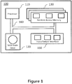
- Figure 1 illustrates a diagram of a computing environment 100 in accordance with an embodiment of the present technology.
- the computing environment 100 may be implemented by any of a conventional personal computer, a server, a router, a switch, a controller, and/or an electronic device (such as, but not limited to, a mobile device, a tablet device, a server, a controller unit, a control device, a monitoring device etc.) and/or any combination thereof appropriate to the relevant task at hand.
- the computing environment 100 comprises various hardware components including one or more single or multi-core processors collectively represented by a processor 110, a solid-state drive 120, a memory device, for example a random access memory 130, and an input/output interface 150.
- the computing environment 100 may be a computer specifically designed for operating in a data center environment.
- the computing environment 100 may be a generic computer system.
- the computing environment 100 may also be a sub-system of one of the above-listed systems. In some embodiments the computing environment 100 may be an "off the shelf' generic computer system. In some embodiments the computing environment 100 may be distributed amongst multiple systems. The computing environment 100 may be specifically dedicated to the implementation of the present technology. As a person skilled in the art of the present technology may appreciate, multiple variations as to how the computing environment 100 is implemented may be envisioned without departing from the scope of the present technology.
- Communication between the various components of the computing environment 100 may be enabled by one or more internal and/or external buses 160 (e.g. a PCI bus, universal serial bus, IEEE 1394 "Firewire” bus, SCSI bus, Serial-ATA bus, ARINC bus, etc.), to which the various hardware components are electronically coupled.
- internal and/or external buses 160 e.g. a PCI bus, universal serial bus, IEEE 1394 "Firewire” bus, SCSI bus, Serial-ATA bus, ARINC bus, etc.
- the input/output interface 150 may provide networking capabilities such as wired or wireless access.
- the input/output interface 150 may comprise a networking interface such as, but not limited to, one or more network ports, one or more network sockets, one or more network interface controllers and the like. Multiple examples of how the networking interface may be implemented will become apparent to the person skilled in the art of the present technology.
- the networking interface may implement specific physical layer and data link layer standard such as Ethernet, Fibre Channel, Wi-Fi, or Token Ring.
- the specific physical layer and the data link layer may provide a base for a full network protocol stack, allowing communication among small groups of computers on the same local area network (LAN) and large-scale network communications through routable protocols, such as Internet Protocol (IP).
- LAN local area network
- IP Internet Protocol
- the solid-state drive 120 stores program instructions suitable for being loaded into the random access memory 130 and executed by the processor 110.
- the program instructions may be part of a library or an application.
- any type of memory may be used in place of the solid-state drive 120, such as a hard disk, optical disk, and/or removable storage media.
- FIG. 2 shows an example of a network configuration according to one or more illustrative aspects of the disclosure.
- Servers 210-13 may comprise servers participating in a virtual network which may be identified by a network identifier.
- the servers 210-13 may be members of a same virtual network.
- the server 213 may act as a gateway which communicates with external services 230.
- the external services 230 may comprise the internet and/or any other services that are external to the virtual network.
- the servers 210-13 may be any devices such as switches or other network devices.
- the servers 210-13 may comprise and/or be in communication with endpoints 220-23, respectively.
- the endpoints 220-23 may encapsulate and/or decapsulate data transmitted via the virtual network.
- Each endpoint 220-23 may comprise a list of addresses of other endpoints 220-23.
- Endpoint 220 may store a list of addresses comprising the addresses of endpoints 221-23.
- the endpoint 220 may determine which other endpoint 221-23 corresponds to the address of the packet. If the server 210 addresses a message to the server 212, the endpoint 220 may determine that the packets are to be transmitted to the endpoint 222. The endpoint 220 may then encapsulate the packets and forward the packets to the endpoint 222. The endpoint 222 may then decapsulate the received packets and provide the packets to the server 212.
- the server 210-12 may transmit and/or receive communications via the server 213 which may act as a gateway. If a device external to the virtual network requests to communicate with one of the servers 210-12 the server 213 may receive the communication from the external device and forward the communication to the requested server 210-12.
- the server 210 may receive information regarding the servers 211-13.
- each of the servers 210-13 may be configured to communicate with each of the other servers 210-13.
- Each endpoint 220-23 may comprise addresses of each of the other endpoints 220-23.
- server 211 may be able to communicate with any of servers 210, 212, and 213. It may be desirable to prevent communications between the servers 210, 211, and/or 212.
- the servers 210, 211, and/or 212 may each be managed by different customers.
- the operator may wish to isolate the servers 210, 211, and/or 212 from each other, the operator may wish for the servers 210, 211, and/or 212 to share network infrastructure, such as the server 213 acting as a gateway.
- the endpoints 220-22 may be configured to prevent communications between the servers 210-12.
- FIG 3 shows an example of a network configuration with restricted communications according to one or more illustrative aspects of the disclosure.
- Servers 310-13 may be members of a same virtual network.
- the servers 310-12 may be prevented from communicating with each other.
- the endpoints 320-22 might not be aware of each other.
- the list of addresses stored by the endpoint 320 might not include the addresses of endpoints 321 and 322.
- the endpoint 320 may search its stored list of addresses for an address for an endpoint corresponding to the server 311. The endpoint 320 might not find the address of endpoint 321 in the list of addresses and thereby might not be able to communicate directly with the endpoint 321 and/or the server 311.
- the server 310 may receive information regarding the server 313 but might not receive information regarding the servers 311-12.
- Each of the servers 310-12 may be able to communicate with server 313 and may be able to access the external services 330 via the server 313.
- the servers 310-12 may belong to a same virtual network but be isolated from each other.
- the servers 310-12 may be isolated from each other at the data link layer of a physical network, i.e. layer 2.
- Each of the servers 310-12 may be able to access shared infrastructure of the virtual network such as the server 313 which may act as a gateway.
- the virtual network may comprise servers that correspond to different customers.
- the virtual network may comprise a maintenance network which is used by network administrators to perform maintenance on the servers in the virtual network.
- servers 310-12 may communicate via a same virtual network but may be isolated from each other. This may be particularly desirable if the servers 310-12 correspond to different customers.
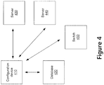
- Figure 4 shows an example of a system for configuring devices according to one or more illustrative aspects of the disclosure.
- the configuration device 410 may be used to configure devices on a network.
- the configuration device 410 may configure devices to operate within a virtual network.
- the configuration device 410 may retrieve information regarding the network from a database 420.
- the database 420 may comprise profiles for each of the devices on the network. Each profile may indicate an address of the device, a physical location of the device, virtual networks corresponding to the device, a type of the device, information describing the hardware of the device, and/or any other information regarding the device.
- the database 420 may store information regarding each of the servers 430 and 440, and/or the switch 450.
- the configuration device 410 may query the database 420 to determine the configurations to be applied to the servers 430 and 440 and/or to the switch 450. Although described as a database 420, any type of storage may be used.
- the servers 430 and 440 may communicate via a virtual network.
- the configuration device 410 may re-configure the server 430, server 440, and/or switch 450 at any time. Each time a device is added and/or removed from the virtual network, the configuration device 410 may reconfigure the server 430, server 440, and/or switch 450.
- Method 500 described below and in figure 5 , is a method that may be executed by the configuration device 410 to configure the server 430, server 440, and/or switch 450.
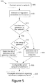
- Figure 5 is a flow diagram of a method for configuring a server according to one or more illustrative aspects of the disclosure.
- the method 500 or one or more steps thereof may be performed by one or more computing devices or entities. Without limitation, all or portions of the method 500 may be executed by the configuration device 410, database 420, servers 430-40, and/or switch 450. All or portions of the method 500 may be performed by components of the computing device 100.
- the method 500 or one or more steps thereof may be embodied in computer-executable instructions that are stored in a computer-readable medium, such as a non-transitory computer-readable medium. Some steps or portions of steps in the flow diagram may be omitted or changed in order.
- a server may be connected to the network. Other events in addition to or instead of the server being connected to the network may trigger the method 500 at step 505.
- the server may have previously been connected to the network and at step 505 be activated.
- An instruction to configure the server may be received at step 505.
- An instruction to configure the server to participate in a virtual network may be received at step 505.
- a change may be detected in a virtual network corresponding to the server. After the change is detected the server may be reconfigured.
- any device that participates in a virtual network may be configured using the method 500.
- a switch, router, gateway, or any other network device may be configured.
- configuration information for the server may be retrieved.
- the configuration information may be retrieved from a database, such as the database 420.
- a configuration device such as the configuration device 410 may query the database to retrieve configuration information for configuring the server.
- the database may comprise information regarding a network on which the server communicates.
- the database may comprise information regarding virtual networks.
- the database may comprise information regarding devices associated with a virtual network.
- the database may comprise the addresses of devices associated with a virtual network.
- the database may be queried to retrieve configuration information regarding the server.
- a determination may be made as to whether there are any gateways on the virtual network.
- a database such as the database 420 may be queried to determine whether there are any gateways on the virtual network.
- the configuration information may indicate whether there are any gateways on the virtual network. If there are no gateways on the virtual network, at step 525 a list of addresses corresponding to all other endpoints of the virtual network may be determined. If there are no specified gateways on the virtual network, every device on the virtual network may be configured as a gateway. If there are one or more gateways on the virtual network, a determination may be made at step 515 as to whether the server is a gateway.
- a determination may be made as to whether the server is a gateway.
- the configuration information may indicate whether the server is a gateway and/or whether the server should be configured as a gateway.
- the database may be queried to determine whether the server is a gateway.
- a gateway may be a device that transfers data between networks. The gateway may receive data from the virtual network and transmit the data on a different virtual or physical network and/or vice versa.
- the database may indicate whether the server should be configured to communicate with all other endpoints on the virtual network or only a portion of the other endpoints on the virtual network.
- a list of addresses corresponding to all other endpoints of the virtual network may be determined.
- the list of addresses may comprise addresses corresponding to both servers acting as gateways and servers that are not acting as gateways. If the server is not a gateway, at step 520 a list of addresses of the endpoints of gateways of the virtual network may be determined. The list of addresses might not comprise endpoints of devices that are not gateways.
- a database such as the database 420 may be queried to determine the addresses of the other endpoints.
- the addresses may comprise IP addresses, MAC addresses, and/or any other type of address that may be used to communicate with the other endpoints.
- the database may be queried at step 525 to determine the addresses of all other endpoints of the virtual network or the database may be queried at step 520 to determine the addresses of the gateway endpoints of the virtual network.
- the server may be configured using the list of addresses determined at step 520 or 525.
- An endpoint corresponding to the server may be configured to communicate on the virtual network.
- the endpoint may be configured to communicate with the endpoints in the list of addresses determined at step 520 or step 525.
- the endpoint of the server may be configured to communicate with all other devices on the virtual network.
- the endpoint of the server may be configured to communicate with gateways on the virtual network.
- the server may be isolated from other servers on the virtual network.
- the server may be isolated at the data link layer, i.e. layer 2, of the physical network on which the server communicates.
- information regarding the server may be propagated to the addresses on the list. If the server is a gateway, at step 535 information regarding the server may be transmitted to all other devices on the virtual network. If the server is not a gateway, at step 535 information regarding the server may be transmitted to gateways on the virtual network.
- the information may comprise an address of the server, an address of an endpoint of the server, and/or any other information regarding the server.
- FIG. 6 shows an example of a network configuration with a test server according to one or more illustrative aspects of the disclosure.
- servers 610-13 are connected via a virtual network.
- the servers 610-13 communicate via their respective endpoints 620-23.
- Servers 612 and 613 may act as gateways which are able to communicate with external services 630.
- Servers 610 and 611 may be isolated from each other such as using the methods described above.
- Endpoint 620 may be configured with a list of endpoint addresses that does not comprise the address of endpoint 621. Similarly, endpoint 621 might not store the address of endpoint 620.
- the server 612 may be a device in the virtual network that is being configured and/or tested.
- the server 612 may be connected to the virtual network for debugging and/or other purposes. Because the server 612 is currently being tested and may be unstable, it might be preferable to prevent the server 612 from processing communications.
- the server 612 may be configured as a gateway but might not yet be trusted to perform gateway functions for the virtual network. Until the server 612 has completed the testing, traffic may be routed to the server 613 instead of the server 612.
- endpoints 620, 621, and/or 623 may be configured to prevent transmissions to the server 612.
- the endpoints 620, 621, and/or 623 might not comprise the address of the endpoint 622 in their respective lists of addresses. In this way the endpoints 620, 621, and/or 623 may be prevented from transmitting packets to the endpoint 622.
- the server 612 may communicate with the servers 610, 611, and/or 613.
- the endpoint 622 of the server 612 may be configured to store the addresses of the endpoints 620, 621, and 623.
- the endpoint 622 may be able to transmit data to the endpoints 620, 621, and/or 623. This may allow the server 612 and/or endpoint 622 to perform various tests within the virtual network, without damaging the stability of the virtual network.
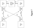
- Figure 7 shows an example of a network configuration with load balancing according to one or more illustrative aspects of the disclosure.
- a network operator may wish to balance the load of various devices within a virtual network. If the network has multiple gateways, network efficiency may be increased by balancing the load between the multiple gateways. Load balancing in a virtual network may be performed by creating and destroying links between devices.
- Servers 710-13 may comprise servers within a virtual network.
- the servers 712 and 713 may act as gateways and may communicate with external services 730 via the links 744 and 745.
- Servers 710 and 711 may use endpoints 720 and 721 to communicate with endpoints 722 and 723 of servers 712 and 713. Using the methods described above the servers 710 and 711 may be prevented from communicating directly with each other.
- a network operator may wish to balance the load between servers 712 and 713.
- links 740-43 may be adjusted. If server 712 is overloaded, links 742 and 740 may be destroyed, or in other words deactivated, in which case all gateway traffic may flow to the server 713. If server 713 is overloaded, links 743 and 741 may be destroyed in which case all gateway traffic may flow to server 712.
- the links 740-43 may be dynamically adjusted based on network load, processor usage, memory usage, response time, and/or any other performance metric.
- the links 740-43 may be dynamically adjusted based on scheduled downtime or other maintenance. For example if maintenance is being performed on server 713 then links 745, 741, and/or 743 may be temporarily destroyed until the maintenance is completed.
- the links 740-43 may be destroyed in which case the endpoints at either end of the link may be adjusted to destroy the link.
- the address of endpoint 722 may be removed from the list of addresses on endpoint 721 and the address of endpoint 721 may be removed from the list of addresses on endpoint 722.
- the endpoint 722 might not be able to communicate with the endpoint 721 and the endpoint 721 might not be able to communicate with the endpoint 722.
- the links may be turned into one-way links in which only one endpoint can transmit data to the other endpoint.
- the address of endpoint 723 may be removed from the list of addresses on endpoint 720.
- the configuration device 410 may dynamically adjust the configuration of a virtual network by creating and/or destroying links between devices on the virtual network.
- the configuration device 410 may receive an indication of network activity corresponding to the virtual network and may adjust the configuration of the virtual network based on the indication.
- the configuration device 410 may manage the load balancing process without the servers 710-13 being configured for load balancing.
- the servers 710-13 might not execute load balancing software.
- the configuration device 410 may perform the load balancing by creating and destroying the links 740-43.
- the load balancing may be performed regardless of whether there is layer 2 connectivity between the servers 710-13. In the example illustrated in figure 7 , the load balancing is performed without layer 2 connectivity between servers 710 and 711, and without layer 2 connectivity between servers 712 and 713.
- FIG. 8 is a flow diagram of a method 800 for configuring a device based on device category according to one or more illustrative aspects of the disclosure.
- Servers and/or other devices may play various roles in a network and may be assigned a category.
- the category of a device may determine which other types of devices the device will be configured to communicate with. For example if a device is a gateway, the gateway may be configured to communicate with all other categories of devices on a virtual network.
- the storage device may be configured to communicate with categories of devices that access the storage device and might not be configured to communicate with categories of devices that do not access the storage device. This may enhance the security and/or stability of the storage by preventing accesses from unauthorized devices.
- the method 800 or one or more steps thereof may be performed by one or more computing devices or entities. Without limitation, all or portions of the method 800 may be executed by the configuration device 410, database 420, servers 430-40, and/or switch 450. All or portions of the method 800 may be performed by components of the computing device 100.
- the method 800 or one or more steps thereof may be embodied in computer-executable instructions that are stored in a computer-readable medium such as a non-transitory computer-readable medium. Some steps or portions of steps in the flow diagram may be omitted or changed in order.
- the device may be connected to a network. Actions performed at step 805 may be similar to those described above in regards to step 505.
- the device may comprise a server, switch, router, storage device, or any other device.
- configuration information for the device may be retrieved. Actions performed at step 805 810 may be similar to those described above in regards to step 510.
- a category of the device may be determined.
- the configuration may indicate the category of the device.
- the categories of devices may be pre-defined such as by a user. Exemplary categories of devices include switches, routers, internal gateways, external gateways, storage servers, web servers, and/or application servers. These categories of devices are exemplary and any categories of devices may be defined and used.
- the categories of other devices that the device can communicate with may be determined.
- the rules for each device category may be pre-defined such as by a user.
- a list of addresses that the device can communicate with may be generated.
- the rules may indicate that an application server may communicate with internal gateways, external gateways, and storage servers.
- an address of an endpoint corresponding to the device may be determined and stored in the list.
- the rules may indicate whether the communication links between devices are one-way or two-way links and the list of addresses may be generated accordingly.
- an endpoint of the device may be configured using the list of addresses. Actions performed at step 830 may be similar to those described above in regards to step 530.
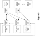
- Figure 9 shows an example of a network configuration with multiple device categories according to one or more illustrative aspects of the disclosure.
- Storage server 910, web server 911, application server 912, internal gateway 913, and external gateway 914 may communicate via a virtual network.
- Each of the devices 910-14 may be configured based on the category of that device.
- the configuration shown in figure 9 is exemplary, any categories and rules may be used for configuring communications between devices.
- the rules applied to the exemplary network illustrated in figure 9 may indicate that the storage server 910 may be configured to communicate with the application server 912 and the web server 921. Accordingly, the endpoint 920 of the storage server 910 may be configured to communicate with the endpoint 921 of the web server 911 and the endpoint 922 of the application server 912. As described above, the endpoint 920 may comprise a list of addresses where the list of addresses may comprise an address for the endpoints 921 and 922. The rules may indicate that the storage server 910 is not to communicate with the internal gateway 912 and the external gateway 914. Thus the list of addresses stored by the endpoint 920 might not comprise an address for the endpoints 923 and 924 of the gateways 913 and 914.
- the web server 911 may be configured to communicate with the storage server 910, the internal gateway 913, and the external gateway 914. Accordingly the endpoint 921 of the web server 911 may comprise addresses for the endpoints 920, 923, and 924.
- the application server 912 may be configured to communicate with the storage server 910, the internal gateway 913, and the external gateway 914. Accordingly the list of addresses of the endpoint 922 may comprise addresses for the endpoints 920, 923, and 924.
- the rules may indicate that the internal gateway 913 may communicate with the storage server 910, the web server 911, and the application server 912.
- the rules may indicate that the internal gateway 913 might not be permitted to communicate with the external gateway 914.
- the endpoint 923 may store a list of addresses comprising addresses for the endpoints 920, 921, and 922.
- the list of addresses stored by the endpoint 923 might not comprise the address of the endpoint 924 corresponding to the external gateway 914.
- the rules may indicate that the external gateway 914 is permitted to communicate with the web server 911 and the application server 912. Accordingly the endpoint 924 may store a list of addresses comprising addresses for the endpoints 921 and 922.
- the external gateway 914 may communicate with external services 930.
- the external services 930 might not be in the virtual network, so the external gateway 914 may communicate with the external services 930 directly rather than through the endpoint 924. Alternatively the external gateway 914 may communicate with the external services 930 via the endpoint 924.
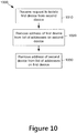
- Figure 10 is a flow diagram of a method 1000 for isolating devices according to one or more illustrative aspects of the disclosure.
- the method 1000 or one or more steps thereof may be performed by one or more computing devices or entities.
- all or portions of the method 1000 may be executed by the configuration device 410, database 420, servers 430-40, and/or switch 450. All or portions of the method 1000 may be performed by components of the computing device 100.
- the method 1000 or one or more steps thereof may be embodied in computer-executable instructions that are stored in a computer-readable medium such as a non-transitory computer-readable medium. Some steps or portions of steps in the flow diagram may be omitted or changed in order.
- a request may be received to isolate a first device from a second device.
- the first device and second device may communicate via a same virtual network.
- the first device and second device may each operate and/or be associated with endpoints.
- the devices may use the endpoints to communicate via the virtual network.
- the request may comprise a request to prevent the first device from communicating with the second device and/or a request to prevent the second device from communicating with the first device.
- an address of the first device may be removed from a list of addresses on the second device.
- Step 1020 may be performed if the request comprises a request to prevent the second device from communicating with the first device.
- the address that is removed may comprise an address of the endpoint associated with the first device.
- a replacement list of addresses may be transmitted to the second device and/or to the endpoint of the second device.
- an address of the second device may be removed from a list of addresses on the first device.
- Step 1030 1030 may be performed if the request comprises a request to prevent the first device from communicating with the second device. Actions performed at step 1030 may be similar to those described above in regards to step 1020
- the first device and the second device may be isolated from each other.
- the isolation may occur at the data link layer of the physical network associated with each of the devices, i.e. layer 2.
- the first device and the second device may be prevented from communicating with each other directly.
Description
- Embodiments described herein relate generally to systems and methods for configuring virtual networks, and more particularly, to systems and methods for isolating devices within virtual networks.
- Virtual networks, such as a virtual extensible local area network (VXLAN), may be used to create a network that appears to be on a single physical network but actually can span multiple physical networks. In a data center providing services for multiple customers, each customer may have their own virtual networks. Using virtual networks may allow each customer's traffic to be virtually isolated from other customers' devices. Each virtual network may be identified by a network identifier such as a VXLAN network identifier (VNI).
- When using a virtual network, devices, such as servers and/or network devices, that are part of the virtual network might not be isolated from each other. It might be possible for a device on the virtual network to communicate with the other devices on the virtual network or discover information about the other devices on the virtual network even if these devices are not intended to access each other. For security and other reasons it may be preferable to isolate all or a portion of the devices within the virtual network from each other. A network operator may wish to control the flow of traffic between devices communicating via the network. For example, a network operator may wish to reduce the amount of traffic received by an overloaded switch. It may be preferable to allow a network operator to control communications between devices.
- The subject matter discussed in the background section should not be assumed to be prior art merely as a result of its mention in the background section. Similarly, a problem mentioned in the background section or associated with the subject matter of the background section should not be assumed to have been previously recognized in the prior art. The subject matter in the background section merely represents different approaches.
-
US 2009/0007218 A1 describes a switched-Based Network Security method. Traffic sent from a network endpoint is redirected and the network endpoint is tested for compliance with a security policy. If the network endpoint is in compliance with the security policy, an access policy is generated to allow the network endpoint to access the network without any traffic redirection. -
US 2017/0093918 A1 describes techniques for constructing network whitelists in server endpoints using host-based security controls. Once constructed, the network whitelists are used to detect unauthorized communications at the server endpoints. A method for constructing a network whitelist includes identifying at least a first application hosted on a computing system. The method also includes inspecting one or more configuration files associated with the first application to identify one or more configuration settings that specify how the first application communicates with one or more second applications. The method further includes generating a whitelist that specifies expected network communications activity for the first application, based on the configuration settings. -
US 2016/0212098 A1 describes a load balancer that can direct Internet Protocol Security (IPsec) traffic received from a single IPsec tunnel initiator to one of a plurality of endpoints provided Virtual Private Network (VPN) gateways in a network. The load balancer uses IP (Internet Protocol) addresses and SPIs (Security Parameter Identifier) to identify an endpoint responsible for processing particular packets for the VPN. Messages received at the load balancer from the endpoints are utilized to map endpoints responsible for processing packets having a particular IP address and SPI for forwarding IPsec traffic to the correct endpoint. - The following summary is for illustrative purposes only and is not intended to limit or constrain the detailed description. The following summary merely presents various described aspects in a simplified form as a prelude to the more detailed description provided below.
- Virtual network technology may be used to encapsulate network packets. Each individual virtual network may be identified by a network identifier. The network identifier may be included in packets originating from and/or traveling to the virtual network.
- Endpoints of the virtual network such as VXLAN tunnel endpoints (VTEPs) may receive packets and remove the encapsulation from those packets. An endpoint may be implemented in a server, switch, hypervisor, and/or any other device. An endpoint may be implemented in software and/or hardware. Each endpoint in a virtual network may comprise a list of addresses of other endpoints in the virtual network. When transmitting a packet the endpoint may transmit the packet to one of the endpoints on the list of addresses. An endpoint may be restricted from transmitting packets to endpoints that are not on the list of addresses because the endpoint might not store addresses of any endpoints other than those on the list of addresses.
- Typically for a virtual network each endpoint associated with the virtual network may comprise an address for every other endpoint associated with the virtual network. The list of addresses stored on an endpoint may comprise an address for each other endpoint on the virtual network.
- A virtual network may comprise devices, such as servers and/or network devices, that are not intended to communicate directly with each other or access each other. In a data center a single virtual network may comprise servers corresponding to multiple customers and/or multiple groups of users. For security reasons it may be preferable to block all communications between servers from different customers and/or different groups of users. In order to prevent servers within a virtual network from communicating with each other, or in other words in order to isolate servers within the virtual network from each other, endpoints may be restricted from communicating with certain other endpoints. In order to isolate a server within a virtual network, the list of addresses stored on an endpoint corresponding to the server may be configured to select which other endpoints the endpoint can communicate with. The isolation may occur at the data link layer of the network, which may be referred to as layer 2.
- Addresses may be dynamically added to and/or removed from the list of addresses stored on an endpoint. In order to reduce traffic to a network device such as a router, the address of the endpoint corresponding to that network device may be removed from the list of addresses stored on other endpoints. The address may be removed permanently or temporarily. The object of the invention is solved by a method according to claim 1 and a system according to claim 10. Preferred embodiments are presented in the dependent claims.
- In the context of the present specification, unless expressly provided otherwise, a computer system may refer, but is not limited to, an "electronic device," an "operation system," a "system," a "computer-based system," a "controller unit," a "monitoring device," a "control device," and/or any combination thereof appropriate to the relevant task at hand.
- In the context of the present specification, unless expressly provided otherwise, the expression "computer-readable medium" and "memory" are intended to comprise media of any nature and kind whatsoever, non-limiting examples of which include RAM, ROM, disks (CD-ROMs, DVDs, floppy disks, hard disk drives, etc.), USB keys, flash memory cards, solid state-drives, and/or tape drives. Still in the context of the present specification, "a" computer-readable medium and "the" computer-readable medium should not be construed as being the same computer-readable medium. To the contrary, and whenever appropriate, "a" computer-readable medium and "the" computer-readable medium may also be construed as a first computer-readable medium and a second computer-readable medium.
- In the context of the present specification, unless expressly provided otherwise, the expression "device" is intended to comprise servers and/or other computer systems, network devices such as switches and routers, virtual machines, and/or any other type of computing devices.
- In the context of the present specification, unless expressly provided otherwise, the words "first," "second," "third," etc. have been used as adjectives only for the purpose of allowing for distinction between the nouns that they modify from one another and not for the purpose of describing any particular relationship between those nouns.
- Implementations of the present technology each may have at least one of the above-mentioned object and/or aspects but do not necessarily have all of them. It should be understood that some aspects of the present technology that have resulted from attempting to attain the above-mentioned object may not satisfy this object and/or may satisfy other objects not specifically recited herein.
- Additional and/or alternative features, aspects and advantages of implementations of the present technology will become apparent from the following description, the accompanying drawings and the appended claims.
- These and other features, aspects, and advantages of the present disclosure will become better understood with regard to the following description, claims, and drawings. The present disclosure is illustrated by way of example, and not limited by, the accompanying figures in which like numerals indicate similar elements.
-
Figure 1 shows an example computing system that may be used to implement any of the methods described herein. -
Figure 2 shows an example of a network configuration according to one or more illustrative aspects of the disclosure. -
Figure 3 shows an example of a network configuration with restricted communications according to one or more illustrative aspects of the disclosure. -
Figure 4 shows an example of a system for configuring devices according to one or more illustrative aspects of the disclosure. -
Figure 5 is a flow diagram of a method for configuring a server according to one or more illustrative aspects of the disclosure. -
Figure 6 shows an example of a network configuration with a test server according to one or more illustrative aspects of the disclosure. -
Figure 7 shows an example of a network configuration with load balancing according to one or more illustrative aspects of the disclosure. -
Figure 8 is a flow diagram of a method for configuring a device based on device category according to one or more illustrative aspects of the disclosure. -
Figure 9 shows an example of a network configuration with multiple device categories according to one or more illustrative aspects of the disclosure. -
Figure 10 is a flow diagram of a method for isolating devices according to one or more illustrative aspects of the disclosure. - In the following description of various illustrative embodiments, reference is made to the accompanying drawings, which form a part hereof, and in which are shown, by way of illustration, various embodiments in which aspects of the disclosure may be practiced. It is to be understood that other embodiments may be utilized, and structural or functional modifications may be made, without departing from the scope of the present disclosure.
- A network virtualization technology such as VXLAN may be used to provide virtual networks. Packets transmitted between devices may be encapsulated with a network identifier such as a VNI to indicate which virtual network the packets are associated with. The virtual network may group devices together even if the devices might not be directly connected to each other. Virtual networks may be isolated from each other. Devices in one virtual network might not be able to communicate with devices in another virtual network. In a data center, different customers might be assigned different virtual networks. In this way one customer might be prevented from accessing another client's servers and/or virtual machines.
- Endpoints such as VTEPs may be used to encapsulate and/or decapsulate packets transmitted on a virtual network. Each endpoint may comprise a list of addresses associated with the virtual network such as IP addresses and/or MAC addresses of other endpoints and/or devices communicating via the other endpoints. An endpoint may communicate with the devices on their list of addresses. An endpoint might not communicate with devices that are not on the list of addresses. The endpoint may retrieve the list of addresses from a database and/or configuration system. The database and/or configuration system may push the list of addresses to the endpoint.
- The list of addresses may be configured to include and/or exclude certain addresses in order to prevent devices that are not intended to communicate directly with each other from communicating with each other within a virtual network. The list of addresses stored in an endpoint may comprise an address for every other endpoint associated with the virtual network of the endpoint. The list of addresses stored in an endpoint may comprise addresses for a subset of the other endpoints associated with the virtual network of the endpoint. The list of addresses may comprise addresses for gateways in the virtual network but might not comprise addresses for other servers in the virtual network.
-
Figure 1 illustrates a diagram of acomputing environment 100 in accordance with an embodiment of the present technology. In some embodiments thecomputing environment 100 may be implemented by any of a conventional personal computer, a server, a router, a switch, a controller, and/or an electronic device (such as, but not limited to, a mobile device, a tablet device, a server, a controller unit, a control device, a monitoring device etc.) and/or any combination thereof appropriate to the relevant task at hand. In some embodiments thecomputing environment 100 comprises various hardware components including one or more single or multi-core processors collectively represented by aprocessor 110, a solid-state drive 120, a memory device, for example arandom access memory 130, and an input/output interface 150. Thecomputing environment 100 may be a computer specifically designed for operating in a data center environment. Thecomputing environment 100 may be a generic computer system. - In some embodiments, the
computing environment 100 may also be a sub-system of one of the above-listed systems. In some embodiments thecomputing environment 100 may be an "off the shelf' generic computer system. In some embodiments thecomputing environment 100 may be distributed amongst multiple systems. Thecomputing environment 100 may be specifically dedicated to the implementation of the present technology. As a person skilled in the art of the present technology may appreciate, multiple variations as to how thecomputing environment 100 is implemented may be envisioned without departing from the scope of the present technology. - Communication between the various components of the
computing environment 100 may be enabled by one or more internal and/or external buses 160 (e.g. a PCI bus, universal serial bus, IEEE 1394 "Firewire" bus, SCSI bus, Serial-ATA bus, ARINC bus, etc.), to which the various hardware components are electronically coupled. - The input/
output interface 150 may provide networking capabilities such as wired or wireless access. As an example, the input/output interface 150 may comprise a networking interface such as, but not limited to, one or more network ports, one or more network sockets, one or more network interface controllers and the like. Multiple examples of how the networking interface may be implemented will become apparent to the person skilled in the art of the present technology. For example, but without being limitative, the networking interface may implement specific physical layer and data link layer standard such as Ethernet, Fibre Channel, Wi-Fi, or Token Ring. The specific physical layer and the data link layer may provide a base for a full network protocol stack, allowing communication among small groups of computers on the same local area network (LAN) and large-scale network communications through routable protocols, such as Internet Protocol (IP). - According to implementations of the present technology, the solid-
state drive 120 stores program instructions suitable for being loaded into therandom access memory 130 and executed by theprocessor 110. For example, the program instructions may be part of a library or an application. Although illustrated as a solid-state drive 120, any type of memory may be used in place of the solid-state drive 120, such as a hard disk, optical disk, and/or removable storage media. -
Figure 2 shows an example of a network configuration according to one or more illustrative aspects of the disclosure. Servers 210-13 may comprise servers participating in a virtual network which may be identified by a network identifier. The servers 210-13 may be members of a same virtual network. - The
server 213 may act as a gateway which communicates withexternal services 230. Theexternal services 230 may comprise the internet and/or any other services that are external to the virtual network. Although illustrated as servers 210-13 the servers 210-13 may be any devices such as switches or other network devices. - The servers 210-13 may comprise and/or be in communication with endpoints 220-23, respectively. The endpoints 220-23 may encapsulate and/or decapsulate data transmitted via the virtual network. Each endpoint 220-23 may comprise a list of addresses of other endpoints 220-23.
Endpoint 220 may store a list of addresses comprising the addresses of endpoints 221-23. When theserver 210 requests to transmit a packet, theendpoint 220 may determine which other endpoint 221-23 corresponds to the address of the packet. If theserver 210 addresses a message to theserver 212, theendpoint 220 may determine that the packets are to be transmitted to theendpoint 222. Theendpoint 220 may then encapsulate the packets and forward the packets to theendpoint 222. Theendpoint 222 may then decapsulate the received packets and provide the packets to theserver 212. - If one of the servers 210-12 requests to communicate with
external services 230, the server 210-12 may transmit and/or receive communications via theserver 213 which may act as a gateway. If a device external to the virtual network requests to communicate with one of the servers 210-12 theserver 213 may receive the communication from the external device and forward the communication to the requested server 210-12. - When the
server 210 performs a scan of the network, theserver 210 may receive information regarding the servers 211-13. In the exemplary networking configuration illustrated infigure 2 each of the servers 210-13 may be configured to communicate with each of the other servers 210-13. Each endpoint 220-23 may comprise addresses of each of the other endpoints 220-23. For example,server 211 may be able to communicate with any ofservers servers servers servers servers server 213 acting as a gateway. As described in further detail below, the endpoints 220-22 may be configured to prevent communications between the servers 210-12. -
Figure 3 shows an example of a network configuration with restricted communications according to one or more illustrative aspects of the disclosure. Servers 310-13 may be members of a same virtual network. In the exemplary network configuration illustrated infigure 3 the servers 310-12 may be prevented from communicating with each other. Unlike infigure 2 in which the endpoints 220-22 were aware of each other, the endpoints 320-22 might not be aware of each other. The list of addresses stored by theendpoint 320 might not include the addresses ofendpoints - If
server 310 were to request to communicate withserver 311, theendpoint 320 may search its stored list of addresses for an address for an endpoint corresponding to theserver 311. Theendpoint 320 might not find the address ofendpoint 321 in the list of addresses and thereby might not be able to communicate directly with theendpoint 321 and/or theserver 311. When theserver 310 performs a scan of the network theserver 310 may receive information regarding theserver 313 but might not receive information regarding the servers 311-12. Each of the servers 310-12 may be able to communicate withserver 313 and may be able to access theexternal services 330 via theserver 313. - By configuring the endpoints 320-22 to be unaware of each other, the servers 310-12 may belong to a same virtual network but be isolated from each other. The servers 310-12 may be isolated from each other at the data link layer of a physical network, i.e. layer 2. Each of the servers 310-12 may be able to access shared infrastructure of the virtual network such as the
server 313 which may act as a gateway. The virtual network may comprise servers that correspond to different customers. The virtual network may comprise a maintenance network which is used by network administrators to perform maintenance on the servers in the virtual network. By configuring the endpoints 320-22, servers 310-12 may communicate via a same virtual network but may be isolated from each other. This may be particularly desirable if the servers 310-12 correspond to different customers. -
Figure 4 shows an example of a system for configuring devices according to one or more illustrative aspects of the disclosure. The configuration device 410 may be used to configure devices on a network. The configuration device 410 may configure devices to operate within a virtual network. The configuration device 410 may retrieve information regarding the network from adatabase 420. Thedatabase 420 may comprise profiles for each of the devices on the network. Each profile may indicate an address of the device, a physical location of the device, virtual networks corresponding to the device, a type of the device, information describing the hardware of the device, and/or any other information regarding the device. - The
database 420 may store information regarding each of theservers switch 450. The configuration device 410 may query thedatabase 420 to determine the configurations to be applied to theservers switch 450. Although described as adatabase 420, any type of storage may be used. After applying a configuration to theservers switch 450, theservers server 430,server 440, and/or switch 450 at any time. Each time a device is added and/or removed from the virtual network, the configuration device 410 may reconfigure theserver 430,server 440, and/orswitch 450.Method 500, described below and infigure 5 , is a method that may be executed by the configuration device 410 to configure theserver 430,server 440, and/orswitch 450. -
Figure 5 is a flow diagram of a method for configuring a server according to one or more illustrative aspects of the disclosure. In one or more embodiments themethod 500 or one or more steps thereof may be performed by one or more computing devices or entities. Without limitation, all or portions of themethod 500 may be executed by the configuration device 410,database 420, servers 430-40, and/orswitch 450. All or portions of themethod 500 may be performed by components of thecomputing device 100. Themethod 500 or one or more steps thereof may be embodied in computer-executable instructions that are stored in a computer-readable medium, such as a non-transitory computer-readable medium. Some steps or portions of steps in the flow diagram may be omitted or changed in order. - At step 505 a server may be connected to the network. Other events in addition to or instead of the server being connected to the network may trigger the
method 500 atstep 505. The server may have previously been connected to the network and atstep 505 be activated. An instruction to configure the server may be received atstep 505. An instruction to configure the server to participate in a virtual network may be received atstep 505. A change may be detected in a virtual network corresponding to the server. After the change is detected the server may be reconfigured. - Although described as a server at
step 505, any device that participates in a virtual network may be configured using themethod 500. A switch, router, gateway, or any other network device may be configured. - At
step 510 configuration information for the server may be retrieved. The configuration information may be retrieved from a database, such as thedatabase 420. A configuration device such as the configuration device 410 may query the database to retrieve configuration information for configuring the server. The database may comprise information regarding a network on which the server communicates. The database may comprise information regarding virtual networks. The database may comprise information regarding devices associated with a virtual network. The database may comprise the addresses of devices associated with a virtual network. The database may be queried to retrieve configuration information regarding the server. - At step 513 a determination may be made as to whether there are any gateways on the virtual network. A database such as the
database 420 may be queried to determine whether there are any gateways on the virtual network. The configuration information may indicate whether there are any gateways on the virtual network. If there are no gateways on the virtual network, at step 525 a list of addresses corresponding to all other endpoints of the virtual network may be determined. If there are no specified gateways on the virtual network, every device on the virtual network may be configured as a gateway. If there are one or more gateways on the virtual network, a determination may be made atstep 515 as to whether the server is a gateway. - At step 515 a determination may be made as to whether the server is a gateway. The configuration information may indicate whether the server is a gateway and/or whether the server should be configured as a gateway. The database may be queried to determine whether the server is a gateway. A gateway may be a device that transfers data between networks. The gateway may receive data from the virtual network and transmit the data on a different virtual or physical network and/or vice versa. The database may indicate whether the server should be configured to communicate with all other endpoints on the virtual network or only a portion of the other endpoints on the virtual network.
- If the server is a gateway, at step 525 a list of addresses corresponding to all other endpoints of the virtual network may be determined. The list of addresses may comprise addresses corresponding to both servers acting as gateways and servers that are not acting as gateways. If the server is not a gateway, at step 520 a list of addresses of the endpoints of gateways of the virtual network may be determined. The list of addresses might not comprise endpoints of devices that are not gateways.
- At
step 520 or 525 a database such as thedatabase 420 may be queried to determine the addresses of the other endpoints. The addresses may comprise IP addresses, MAC addresses, and/or any other type of address that may be used to communicate with the other endpoints. The database may be queried atstep 525 to determine the addresses of all other endpoints of the virtual network or the database may be queried atstep 520 to determine the addresses of the gateway endpoints of the virtual network. - At
step 530 the server may be configured using the list of addresses determined atstep step 520 orstep 525. If the server is a gateway, atstep 530 the endpoint of the server may be configured to communicate with all other devices on the virtual network. If the server is not a gateway, atstep 530 the endpoint of the server may be configured to communicate with gateways on the virtual network. If the server is not a gateway the server may be isolated from other servers on the virtual network. The server may be isolated at the data link layer, i.e. layer 2, of the physical network on which the server communicates. - At
step 535 information regarding the server may be propagated to the addresses on the list. If the server is a gateway, atstep 535 information regarding the server may be transmitted to all other devices on the virtual network. If the server is not a gateway, atstep 535 information regarding the server may be transmitted to gateways on the virtual network. The information may comprise an address of the server, an address of an endpoint of the server, and/or any other information regarding the server. -
Figure 6 shows an example of a network configuration with a test server according to one or more illustrative aspects of the disclosure. In the exemplary network illustrated infigure 6 servers 610-13 are connected via a virtual network. The servers 610-13 communicate via their respective endpoints 620-23.Servers external services 630. -
Servers Endpoint 620 may be configured with a list of endpoint addresses that does not comprise the address ofendpoint 621. Similarly,endpoint 621 might not store the address ofendpoint 620. - The
server 612 may be a device in the virtual network that is being configured and/or tested. Theserver 612 may be connected to the virtual network for debugging and/or other purposes. Because theserver 612 is currently being tested and may be unstable, it might be preferable to prevent theserver 612 from processing communications. Theserver 612 may be configured as a gateway but might not yet be trusted to perform gateway functions for the virtual network. Until theserver 612 has completed the testing, traffic may be routed to theserver 613 instead of theserver 612. - In order to prevent incoming traffic from being sent to the
server 612,endpoints server 612. Theendpoints endpoint 622 in their respective lists of addresses. In this way theendpoints endpoint 622. - In order to perform testing of the
server 612, theserver 612 may communicate with theservers endpoint 622 of theserver 612 may be configured to store the addresses of theendpoints endpoints endpoint 622, theendpoint 622 may be able to transmit data to theendpoints server 612 and/orendpoint 622 to perform various tests within the virtual network, without damaging the stability of the virtual network. -
Figure 7 shows an example of a network configuration with load balancing according to one or more illustrative aspects of the disclosure. A network operator may wish to balance the load of various devices within a virtual network. If the network has multiple gateways, network efficiency may be increased by balancing the load between the multiple gateways. Load balancing in a virtual network may be performed by creating and destroying links between devices. - Servers 710-13 may comprise servers within a virtual network. The
servers external services 730 via thelinks Servers endpoints endpoints servers servers - A network operator may wish to balance the load between
servers server 712 is overloaded,links server 713. Ifserver 713 is overloaded,links server 712. - The links 740-43 may be dynamically adjusted based on network load, processor usage, memory usage, response time, and/or any other performance metric. The links 740-43 may be dynamically adjusted based on scheduled downtime or other maintenance. For example if maintenance is being performed on
server 713 then links 745, 741, and/or 743 may be temporarily destroyed until the maintenance is completed. - The links 740-43 may be destroyed in which case the endpoints at either end of the link may be adjusted to destroy the link. To destroy the
link 742, the address ofendpoint 722 may be removed from the list of addresses onendpoint 721 and the address ofendpoint 721 may be removed from the list of addresses onendpoint 722. Thus, theendpoint 722 might not be able to communicate with theendpoint 721 and theendpoint 721 might not be able to communicate with theendpoint 722. Alternatively the links may be turned into one-way links in which only one endpoint can transmit data to the other endpoint. To turn thelink 741 into a one-way link the address ofendpoint 723 may be removed from the list of addresses onendpoint 720. - The configuration device 410 may dynamically adjust the configuration of a virtual network by creating and/or destroying links between devices on the virtual network. The configuration device 410 may receive an indication of network activity corresponding to the virtual network and may adjust the configuration of the virtual network based on the indication.
- The configuration device 410 may manage the load balancing process without the servers 710-13 being configured for load balancing. The servers 710-13 might not execute load balancing software. The configuration device 410 may perform the load balancing by creating and destroying the links 740-43. The load balancing may be performed regardless of whether there is layer 2 connectivity between the servers 710-13. In the example illustrated in
figure 7 , the load balancing is performed without layer 2 connectivity betweenservers servers -
Figure 8 is a flow diagram of amethod 800 for configuring a device based on device category according to one or more illustrative aspects of the disclosure. Servers and/or other devices may play various roles in a network and may be assigned a category. The category of a device may determine which other types of devices the device will be configured to communicate with. For example if a device is a gateway, the gateway may be configured to communicate with all other categories of devices on a virtual network. In another example if a device is a storage device, the storage device may be configured to communicate with categories of devices that access the storage device and might not be configured to communicate with categories of devices that do not access the storage device. This may enhance the security and/or stability of the storage by preventing accesses from unauthorized devices. - In one or more embodiments the
method 800 or one or more steps thereof may be performed by one or more computing devices or entities. Without limitation, all or portions of themethod 800 may be executed by the configuration device 410,database 420, servers 430-40, and/orswitch 450. All or portions of themethod 800 may be performed by components of thecomputing device 100. Themethod 800 or one or more steps thereof may be embodied in computer-executable instructions that are stored in a computer-readable medium such as a non-transitory computer-readable medium. Some steps or portions of steps in the flow diagram may be omitted or changed in order. - At
step 805 the device may be connected to a network. Actions performed atstep 805 may be similar to those described above in regards to step 505. The device may comprise a server, switch, router, storage device, or any other device. - At
step 810 configuration information for the device may be retrieved. Actions performed atstep 805 810 may be similar to those described above in regards to step 510. At step 815 a category of the device may be determined. The configuration may indicate the category of the device. The categories of devices may be pre-defined such as by a user. Exemplary categories of devices include switches, routers, internal gateways, external gateways, storage servers, web servers, and/or application servers. These categories of devices are exemplary and any categories of devices may be defined and used. - At
step 820 the categories of other devices that the device can communicate with may be determined. The rules for each device category may be pre-defined such as by a user. At step 825 a list of addresses that the device can communicate with may be generated. For example the rules may indicate that an application server may communicate with internal gateways, external gateways, and storage servers. In this example if the device were determined to be an application server atstep 815, then for each internal gateway, external gateway and storage server in the virtual network an address of an endpoint corresponding to the device may be determined and stored in the list. The rules may indicate whether the communication links between devices are one-way or two-way links and the list of addresses may be generated accordingly. - At
step 830 an endpoint of the device may be configured using the list of addresses. Actions performed atstep 830 may be similar to those described above in regards to step 530. -
Figure 9 shows an example of a network configuration with multiple device categories according to one or more illustrative aspects of the disclosure.Storage server 910,web server 911,application server 912,internal gateway 913, andexternal gateway 914 may communicate via a virtual network. Each of the devices 910-14 may be configured based on the category of that device. The configuration shown infigure 9 is exemplary, any categories and rules may be used for configuring communications between devices. - The rules applied to the exemplary network illustrated in
figure 9 may indicate that thestorage server 910 may be configured to communicate with theapplication server 912 and theweb server 921. Accordingly, theendpoint 920 of thestorage server 910 may be configured to communicate with theendpoint 921 of theweb server 911 and theendpoint 922 of theapplication server 912. As described above, theendpoint 920 may comprise a list of addresses where the list of addresses may comprise an address for theendpoints storage server 910 is not to communicate with theinternal gateway 912 and theexternal gateway 914. Thus the list of addresses stored by theendpoint 920 might not comprise an address for theendpoints gateways - The
web server 911 may be configured to communicate with thestorage server 910, theinternal gateway 913, and theexternal gateway 914. Accordingly theendpoint 921 of theweb server 911 may comprise addresses for theendpoints application server 912 may be configured to communicate with thestorage server 910, theinternal gateway 913, and theexternal gateway 914. Accordingly the list of addresses of theendpoint 922 may comprise addresses for theendpoints - The rules may indicate that the
internal gateway 913 may communicate with thestorage server 910, theweb server 911, and theapplication server 912. The rules may indicate that theinternal gateway 913 might not be permitted to communicate with theexternal gateway 914. Accordingly, theendpoint 923 may store a list of addresses comprising addresses for theendpoints endpoint 923 might not comprise the address of theendpoint 924 corresponding to theexternal gateway 914. - The rules may indicate that the
external gateway 914 is permitted to communicate with theweb server 911 and theapplication server 912. Accordingly theendpoint 924 may store a list of addresses comprising addresses for theendpoints external gateway 914 may communicate withexternal services 930. Theexternal services 930 might not be in the virtual network, so theexternal gateway 914 may communicate with theexternal services 930 directly rather than through theendpoint 924. Alternatively theexternal gateway 914 may communicate with theexternal services 930 via theendpoint 924. -
Figure 10 is a flow diagram of amethod 1000 for isolating devices according to one or more illustrative aspects of the disclosure. In one or more embodiments themethod 1000 or one or more steps thereof may be performed by one or more computing devices or entities. Without limitation, all or portions of themethod 1000 may be executed by the configuration device 410,database 420, servers 430-40, and/orswitch 450. All or portions of themethod 1000 may be performed by components of thecomputing device 100. Themethod 1000 or one or more steps thereof may be embodied in computer-executable instructions that are stored in a computer-readable medium such as a non-transitory computer-readable medium. Some steps or portions of steps in the flow diagram may be omitted or changed in order. - At step 1010 a request may be received to isolate a first device from a second device. The first device and second device may communicate via a same virtual network. The first device and second device may each operate and/or be associated with endpoints. The devices may use the endpoints to communicate via the virtual network. The request may comprise a request to prevent the first device from communicating with the second device and/or a request to prevent the second device from communicating with the first device.
- At
step 1020 an address of the first device may be removed from a list of addresses on the second device.Step 1020 may be performed if the request comprises a request to prevent the second device from communicating with the first device. The address that is removed may comprise an address of the endpoint associated with the first device. To remove the address a replacement list of addresses may be transmitted to the second device and/or to the endpoint of the second device. - At
step 1030 an address of the second device may be removed from a list of addresses on the first device.Step 1030 1030 may be performed if the request comprises a request to prevent the first device from communicating with the second device. Actions performed atstep 1030 may be similar to those described above in regards to step 1020 - After removing the addresses at
step - While the above-described implementations have been described and shown with reference to particular steps performed in a particular order, it will be understood that these steps may be combined, sub-divided, or re-ordered without departing from the teachings of the present technology. At least some of the steps may be executed in parallel or in series. Accordingly the order and grouping of the steps is not a limitation of the present technology.
- It should be expressly understood that not all technical effects mentioned herein need to be enjoyed in each and every embodiment of the present technology.
- Modifications and improvements to the above-described implementations of the present technology may become apparent to those skilled in the art. The foregoing description is intended to be exemplary rather than limiting. The scope of the present technology is therefore intended to be limited solely by the scope of the appended claims.
Claims (10)
- A method for operating network devices, the method comprising:storing, in a first endpoint (220-223, 320-323, 620-623, 720-723, 920-923) of a first device (210-213, 310-313, 610-613, 710-713, 910-913), a first list of addresses of other endpoints within a virtual network which the first endpoint is aware of and with which the first endpoint is authorized to communicate;storing, in a second endpoint (220-223, 320-323, 620-623, 720-723, 920-923) of a second device (210-213, 310-313, 610-613, 710-713, 910-913), a second list of addresses of other endpoints within the virtual network with which the second endpoint is authorized to communicate;receiving, at the first device, a request to isolate the first device from the second device;receiving, at the second device, a request to isolate the second device from the first device;determining, at the second device, a first address of the first endpoint corresponding to the first device in the second list;determining, at the first device, a second address of the second endpoint corresponding to the second device in the first list;configuring the first endpoint to prevent communications of the first endpoint with the second endpoint by removing the second address of the second endpoint from the first list of addresses stored in the first endpoint; andconfiguring the second endpoint to prevent communications of the second endpoint with the first endpoint by removing the first address of the first endpoint from the second list of addresses stored in the second endpoint;wherein:the first endpoint is unaware of any endpoint not on the first list and is restricted to communicating therewith;the second endpoint is unaware of any endpoint not on the second list and is restricted to communicating therewith; andthe first device and the second device communicate in the virtual network via the first endpoint and the second endpoint.
- The method of claim 1, further comprising transmitting, to the first device, the first list of addresses of the other endpoints within the virtual network.
- The method of claim 1, further comprising:configuring the first endpoint to communicate with a gateway (213); andconfiguring the second endpoint to communicate with the gateway.
- The method of claim 3, further comprising:causing the first endpoint to store a third address of a third endpoint corresponding to the gateway; andcausing the second endpoint to store the third address of the third endpoint.
- The method of claim 1, wherein the first and second devices are associated with different groups of users.
- The method of claim 1, further comprising:querying a database (420) for the first address of the first endpoint; andquerying the database for the second address of the second endpoint.
- The method of claim 1, further comprising:determining whether a third endpoint associated with the virtual network is configured as a gateway;after determining that the third endpoint is configured as a gateway, configuring the first endpoint and the second endpoint to communicate with the third endpoint.
- The method of claim 7, further comprising:transmitting, to the first endpoint, a third address of the third endpoint; andtransmitting, to the second endpoint, the third address of the third endpoint.
- The method of claim 1, wherein the virtual network comprises a network used for performing maintenance on the first device and the second device.
- A system, comprising:a first device, comprising:at least one first processor (110); anda first memory device (130) comprising executable instructions, which, when executed by the at least one first processor, cause the first device to perform operations of the first device as defined in the method of any one of claims 1 to 9; anda second device, comprising:at least one second processor (110); anda second memory device (130) comprising executable instructions, which, when executed by the at least one second processor, cause the second device to perform operations of the second device as defined in the method of any one of claims 1 to 9.
Priority Applications (5)
| Application Number | Priority Date | Filing Date | Title |
|---|---|---|---|
| EP18315045.7A EP3661150B1 (en) | 2018-11-29 | 2018-11-29 | Systems and methods for configuring virtual networks |
| DK18315045.7T DK3661150T3 (en) | 2018-11-29 | 2018-11-29 | SYSTEMS AND METHODS FOR CONFIGURING VIRTUAL NETWORKS |
| CA3062771A CA3062771A1 (en) | 2018-11-29 | 2019-11-27 | Systems and methods for configuring virtual networks |
| US16/698,511 US11133960B2 (en) | 2018-11-29 | 2019-11-27 | Systems and methods for configuring virtual networks |
| CN201911199915.9A CN111245698B (en) | 2018-11-29 | 2019-11-29 | Method and apparatus for operating network device |
Applications Claiming Priority (1)
| Application Number | Priority Date | Filing Date | Title |
|---|---|---|---|
| EP18315045.7A EP3661150B1 (en) | 2018-11-29 | 2018-11-29 | Systems and methods for configuring virtual networks |
Publications (2)
| Publication Number | Publication Date |
|---|---|
| EP3661150A1 EP3661150A1 (en) | 2020-06-03 |
| EP3661150B1 true EP3661150B1 (en) | 2020-10-21 |
Family
ID=65657185
Family Applications (1)
| Application Number | Title | Priority Date | Filing Date |
|---|---|---|---|
| EP18315045.7A Active EP3661150B1 (en) | 2018-11-29 | 2018-11-29 | Systems and methods for configuring virtual networks |
Country Status (5)
| Country | Link |
|---|---|
| US (1) | US11133960B2 (en) |
| EP (1) | EP3661150B1 (en) |
| CN (1) | CN111245698B (en) |
| CA (1) | CA3062771A1 (en) |
| DK (1) | DK3661150T3 (en) |
Family Cites Families (4)
| Publication number | Priority date | Publication date | Assignee | Title |
|---|---|---|---|---|
| US20090007218A1 (en) * | 2007-06-30 | 2009-01-01 | Hubbard Scott M | Switched-Based Network Security |
| US10348767B1 (en) * | 2013-02-26 | 2019-07-09 | Zentera Systems, Inc. | Cloud over IP session layer network |
| US9565167B2 (en) * | 2015-01-21 | 2017-02-07 | Huawei Technologies Co., Ltd. | Load balancing internet protocol security tunnels |
| US10291654B2 (en) * | 2015-09-30 | 2019-05-14 | Symantec Corporation | Automated construction of network whitelists using host-based security controls |
-
2018
- 2018-11-29 EP EP18315045.7A patent/EP3661150B1/en active Active
- 2018-11-29 DK DK18315045.7T patent/DK3661150T3/en active
-
2019
- 2019-11-27 US US16/698,511 patent/US11133960B2/en active Active
- 2019-11-27 CA CA3062771A patent/CA3062771A1/en active Pending
- 2019-11-29 CN CN201911199915.9A patent/CN111245698B/en active Active
Non-Patent Citations (1)
| Title |
|---|
| None * |
Also Published As
| Publication number | Publication date |
|---|---|
| DK3661150T3 (en) | 2020-11-16 |
| US11133960B2 (en) | 2021-09-28 |
| CN111245698A (en) | 2020-06-05 |
| US20200177415A1 (en) | 2020-06-04 |
| CA3062771A1 (en) | 2020-05-29 |
| CN111245698B (en) | 2022-09-09 |
| EP3661150A1 (en) | 2020-06-03 |
Similar Documents
| Publication | Publication Date | Title |
|---|---|---|
| US11924033B2 (en) | Discovery of network load balancers | |
| US10986139B2 (en) | Micro-segmentation in virtualized computing environments | |
| EP2888838B1 (en) | A framework for networking and security services in virtual networks | |
| US9203865B2 (en) | Cluster architecture for network security processing | |
| EP3070881B1 (en) | Link health check method and device | |
| US20150229641A1 (en) | Migration of a security policy of a virtual machine | |
| EP2525532A1 (en) | Method and apparatus of connectivity discovery between network switch and server based on vlan identifiers | |
| US10693860B2 (en) | RDP proxy support in presence of RDP server farm with session directory or broker | |
| US20190075080A1 (en) | System and method for providing secure and redundant communications and processing for a collection of internet of things (iot) devices | |
| US20060256735A1 (en) | Method and apparatus for centrally configuring network devices | |
| JP5928197B2 (en) | Storage system management program and storage system management apparatus | |
| CN110301125B (en) | Logical port authentication for virtual machines | |
| US8060592B1 (en) | Selectively updating network devices by a network management application | |
| US20220286515A1 (en) | Policy-based connection provisioning using domain name system (dns) requests | |
| EP3661150B1 (en) | Systems and methods for configuring virtual networks | |
| WO2023020606A1 (en) | Method, system and apparatus for hiding source station, and device and storage medium | |
| US20220116379A1 (en) | Context-aware network policy enforcement | |
| US20210226899A1 (en) | Signature based management of packets in a software defined networking environment | |
| US10536383B2 (en) | Attribute enhancement for handling network packet traffic between micro segmented guests | |
| JP6153903B2 (en) | Service chaining system, service chaining policy control apparatus, and service chaining method | |
| Aderholdt et al. | Multi-tenant isolation via reconfigurable networks |
Legal Events
| Date | Code | Title | Description |
|---|---|---|---|
| PUAI | Public reference made under article 153(3) epc to a published international application that has entered the european phase |
Free format text: ORIGINAL CODE: 0009012 |
|
| STAA | Information on the status of an ep patent application or granted ep patent |
Free format text: STATUS: REQUEST FOR EXAMINATION WAS MADE |
|
| 17P | Request for examination filed |
Effective date: 20200130 |
|
| AK | Designated contracting states |
Kind code of ref document: A1 Designated state(s): AL AT BE BG CH CY CZ DE DK EE ES FI FR GB GR HR HU IE IS IT LI LT LU LV MC MK MT NL NO PL PT RO RS SE SI SK SM TR |
|
| AX | Request for extension of the european patent |
Extension state: BA ME |
|
| GRAP | Despatch of communication of intention to grant a patent |
Free format text: ORIGINAL CODE: EPIDOSNIGR1 |
|
| STAA | Information on the status of an ep patent application or granted ep patent |
Free format text: STATUS: GRANT OF PATENT IS INTENDED |
|
| GRAS | Grant fee paid |
Free format text: ORIGINAL CODE: EPIDOSNIGR3 |
|
| GRAJ | Information related to disapproval of communication of intention to grant by the applicant or resumption of examination proceedings by the epo deleted |
Free format text: ORIGINAL CODE: EPIDOSDIGR1 |
|
| GRAL | Information related to payment of fee for publishing/printing deleted |
Free format text: ORIGINAL CODE: EPIDOSDIGR3 |
|
| STAA | Information on the status of an ep patent application or granted ep patent |
Free format text: STATUS: REQUEST FOR EXAMINATION WAS MADE |
|
| INTG | Intention to grant announced |
Effective date: 20200715 |
|
| INTC | Intention to grant announced (deleted) | ||
| GRAP | Despatch of communication of intention to grant a patent |
Free format text: ORIGINAL CODE: EPIDOSNIGR1 |
|
| STAA | Information on the status of an ep patent application or granted ep patent |
Free format text: STATUS: GRANT OF PATENT IS INTENDED |
|
| GRAA | (expected) grant |
Free format text: ORIGINAL CODE: 0009210 |
|
| STAA | Information on the status of an ep patent application or granted ep patent |
Free format text: STATUS: THE PATENT HAS BEEN GRANTED |
|
| INTG | Intention to grant announced |
Effective date: 20200904 |
|
| AK | Designated contracting states |
Kind code of ref document: B1 Designated state(s): AL AT BE BG CH CY CZ DE DK EE ES FI FR GB GR HR HU IE IS IT LI LT LU LV MC MK MT NL NO PL PT RO RS SE SI SK SM TR |
|
| REG | Reference to a national code |
Ref country code: GB Ref legal event code: FG4D |
|
| REG | Reference to a national code |
Ref country code: CH Ref legal event code: EP |
|
| REG | Reference to a national code |
Ref country code: IE Ref legal event code: FG4D |
|
| REG | Reference to a national code |
Ref country code: DE Ref legal event code: R096 Ref document number: 602018008947 Country of ref document: DE |
|
| REG | Reference to a national code |
Ref country code: AT Ref legal event code: REF Ref document number: 1326999 Country of ref document: AT Kind code of ref document: T Effective date: 20201115 |
|
| REG | Reference to a national code |
Ref country code: DK Ref legal event code: T3 Effective date: 20201113 |
|
| REG | Reference to a national code |
Ref country code: NL Ref legal event code: FP |
|
| REG | Reference to a national code |
Ref country code: AT Ref legal event code: MK05 Ref document number: 1326999 Country of ref document: AT Kind code of ref document: T Effective date: 20201021 |
|
| PG25 | Lapsed in a contracting state [announced via postgrant information from national office to epo] |
Ref country code: NO Free format text: LAPSE BECAUSE OF FAILURE TO SUBMIT A TRANSLATION OF THE DESCRIPTION OR TO PAY THE FEE WITHIN THE PRESCRIBED TIME-LIMIT Effective date: 20210121 Ref country code: GR Free format text: LAPSE BECAUSE OF FAILURE TO SUBMIT A TRANSLATION OF THE DESCRIPTION OR TO PAY THE FEE WITHIN THE PRESCRIBED TIME-LIMIT Effective date: 20210122 Ref country code: FI Free format text: LAPSE BECAUSE OF FAILURE TO SUBMIT A TRANSLATION OF THE DESCRIPTION OR TO PAY THE FEE WITHIN THE PRESCRIBED TIME-LIMIT Effective date: 20201021 Ref country code: RS Free format text: LAPSE BECAUSE OF FAILURE TO SUBMIT A TRANSLATION OF THE DESCRIPTION OR TO PAY THE FEE WITHIN THE PRESCRIBED TIME-LIMIT Effective date: 20201021 Ref country code: PT Free format text: LAPSE BECAUSE OF FAILURE TO SUBMIT A TRANSLATION OF THE DESCRIPTION OR TO PAY THE FEE WITHIN THE PRESCRIBED TIME-LIMIT Effective date: 20210222 |
|
| REG | Reference to a national code |
Ref country code: LT Ref legal event code: MG4D |
|
| PG25 | Lapsed in a contracting state [announced via postgrant information from national office to epo] |
Ref country code: ES Free format text: LAPSE BECAUSE OF FAILURE TO SUBMIT A TRANSLATION OF THE DESCRIPTION OR TO PAY THE FEE WITHIN THE PRESCRIBED TIME-LIMIT Effective date: 20201021 Ref country code: AT Free format text: LAPSE BECAUSE OF FAILURE TO SUBMIT A TRANSLATION OF THE DESCRIPTION OR TO PAY THE FEE WITHIN THE PRESCRIBED TIME-LIMIT Effective date: 20201021 Ref country code: SE Free format text: LAPSE BECAUSE OF FAILURE TO SUBMIT A TRANSLATION OF THE DESCRIPTION OR TO PAY THE FEE WITHIN THE PRESCRIBED TIME-LIMIT Effective date: 20201021 Ref country code: IS Free format text: LAPSE BECAUSE OF FAILURE TO SUBMIT A TRANSLATION OF THE DESCRIPTION OR TO PAY THE FEE WITHIN THE PRESCRIBED TIME-LIMIT Effective date: 20210221 Ref country code: LV Free format text: LAPSE BECAUSE OF FAILURE TO SUBMIT A TRANSLATION OF THE DESCRIPTION OR TO PAY THE FEE WITHIN THE PRESCRIBED TIME-LIMIT Effective date: 20201021 Ref country code: BG Free format text: LAPSE BECAUSE OF FAILURE TO SUBMIT A TRANSLATION OF THE DESCRIPTION OR TO PAY THE FEE WITHIN THE PRESCRIBED TIME-LIMIT Effective date: 20210121 |
|
| PG25 | Lapsed in a contracting state [announced via postgrant information from national office to epo] |
Ref country code: HR Free format text: LAPSE BECAUSE OF FAILURE TO SUBMIT A TRANSLATION OF THE DESCRIPTION OR TO PAY THE FEE WITHIN THE PRESCRIBED TIME-LIMIT Effective date: 20201021 |
|
| REG | Reference to a national code |
Ref country code: DE Ref legal event code: R097 Ref document number: 602018008947 Country of ref document: DE |
|
| PG25 | Lapsed in a contracting state [announced via postgrant information from national office to epo] |
Ref country code: LU Free format text: LAPSE BECAUSE OF NON-PAYMENT OF DUE FEES Effective date: 20201129 Ref country code: MC Free format text: LAPSE BECAUSE OF FAILURE TO SUBMIT A TRANSLATION OF THE DESCRIPTION OR TO PAY THE FEE WITHIN THE PRESCRIBED TIME-LIMIT Effective date: 20201021 Ref country code: LT Free format text: LAPSE BECAUSE OF FAILURE TO SUBMIT A TRANSLATION OF THE DESCRIPTION OR TO PAY THE FEE WITHIN THE PRESCRIBED TIME-LIMIT Effective date: 20201021 Ref country code: RO Free format text: LAPSE BECAUSE OF FAILURE TO SUBMIT A TRANSLATION OF THE DESCRIPTION OR TO PAY THE FEE WITHIN THE PRESCRIBED TIME-LIMIT Effective date: 20201021 Ref country code: SK Free format text: LAPSE BECAUSE OF FAILURE TO SUBMIT A TRANSLATION OF THE DESCRIPTION OR TO PAY THE FEE WITHIN THE PRESCRIBED TIME-LIMIT Effective date: 20201021 Ref country code: SM Free format text: LAPSE BECAUSE OF FAILURE TO SUBMIT A TRANSLATION OF THE DESCRIPTION OR TO PAY THE FEE WITHIN THE PRESCRIBED TIME-LIMIT Effective date: 20201021 Ref country code: EE Free format text: LAPSE BECAUSE OF FAILURE TO SUBMIT A TRANSLATION OF THE DESCRIPTION OR TO PAY THE FEE WITHIN THE PRESCRIBED TIME-LIMIT Effective date: 20201021 Ref country code: CZ Free format text: LAPSE BECAUSE OF FAILURE TO SUBMIT A TRANSLATION OF THE DESCRIPTION OR TO PAY THE FEE WITHIN THE PRESCRIBED TIME-LIMIT Effective date: 20201021 |
|
| REG | Reference to a national code |
Ref country code: BE Ref legal event code: MM Effective date: 20201130 |
|
| PLBE | No opposition filed within time limit |
Free format text: ORIGINAL CODE: 0009261 |
|
| STAA | Information on the status of an ep patent application or granted ep patent |
Free format text: STATUS: NO OPPOSITION FILED WITHIN TIME LIMIT |
|
| REG | Reference to a national code |
Ref country code: IE Ref legal event code: MM4A |
|
| 26N | No opposition filed |
Effective date: 20210722 |
|
| PG25 | Lapsed in a contracting state [announced via postgrant information from national office to epo] |
Ref country code: AL Free format text: LAPSE BECAUSE OF FAILURE TO SUBMIT A TRANSLATION OF THE DESCRIPTION OR TO PAY THE FEE WITHIN THE PRESCRIBED TIME-LIMIT Effective date: 20201021 Ref country code: IE Free format text: LAPSE BECAUSE OF NON-PAYMENT OF DUE FEES Effective date: 20201129 Ref country code: IT Free format text: LAPSE BECAUSE OF FAILURE TO SUBMIT A TRANSLATION OF THE DESCRIPTION OR TO PAY THE FEE WITHIN THE PRESCRIBED TIME-LIMIT Effective date: 20201021 |
|
| REG | Reference to a national code |
Ref country code: DE Ref legal event code: R079 Ref document number: 602018008947 Country of ref document: DE Free format text: PREVIOUS MAIN CLASS: H04L0029060000 Ipc: H04L0065000000 |
|
| PG25 | Lapsed in a contracting state [announced via postgrant information from national office to epo] |
Ref country code: SI Free format text: LAPSE BECAUSE OF FAILURE TO SUBMIT A TRANSLATION OF THE DESCRIPTION OR TO PAY THE FEE WITHIN THE PRESCRIBED TIME-LIMIT Effective date: 20201021 |
|
| PG25 | Lapsed in a contracting state [announced via postgrant information from national office to epo] |
Ref country code: IS Free format text: LAPSE BECAUSE OF FAILURE TO SUBMIT A TRANSLATION OF THE DESCRIPTION OR TO PAY THE FEE WITHIN THE PRESCRIBED TIME-LIMIT Effective date: 20210221 Ref country code: TR Free format text: LAPSE BECAUSE OF FAILURE TO SUBMIT A TRANSLATION OF THE DESCRIPTION OR TO PAY THE FEE WITHIN THE PRESCRIBED TIME-LIMIT Effective date: 20201021 Ref country code: MT Free format text: LAPSE BECAUSE OF FAILURE TO SUBMIT A TRANSLATION OF THE DESCRIPTION OR TO PAY THE FEE WITHIN THE PRESCRIBED TIME-LIMIT Effective date: 20201021 Ref country code: CY Free format text: LAPSE BECAUSE OF FAILURE TO SUBMIT A TRANSLATION OF THE DESCRIPTION OR TO PAY THE FEE WITHIN THE PRESCRIBED TIME-LIMIT Effective date: 20201021 |
|
| PG25 | Lapsed in a contracting state [announced via postgrant information from national office to epo] |
Ref country code: MK Free format text: LAPSE BECAUSE OF FAILURE TO SUBMIT A TRANSLATION OF THE DESCRIPTION OR TO PAY THE FEE WITHIN THE PRESCRIBED TIME-LIMIT Effective date: 20201021 |
|
| REG | Reference to a national code |
Ref country code: CH Ref legal event code: PL |
|
| PG25 | Lapsed in a contracting state [announced via postgrant information from national office to epo] |
Ref country code: BE Free format text: LAPSE BECAUSE OF NON-PAYMENT OF DUE FEES Effective date: 20201130 |
|
| PG25 | Lapsed in a contracting state [announced via postgrant information from national office to epo] |
Ref country code: LI Free format text: LAPSE BECAUSE OF NON-PAYMENT OF DUE FEES Effective date: 20211130 Ref country code: CH Free format text: LAPSE BECAUSE OF NON-PAYMENT OF DUE FEES Effective date: 20211130 |
|
| PGFP | Annual fee paid to national office [announced via postgrant information from national office to epo] |
Ref country code: NL Payment date: 20221114 Year of fee payment: 5 Ref country code: DK Payment date: 20221122 Year of fee payment: 5 |
|
| PGFP | Annual fee paid to national office [announced via postgrant information from national office to epo] |
Ref country code: PL Payment date: 20221118 Year of fee payment: 5 |
|
| P01 | Opt-out of the competence of the unified patent court (upc) registered |
Effective date: 20230513 |
|
| PGFP | Annual fee paid to national office [announced via postgrant information from national office to epo] |
Ref country code: GB Payment date: 20231109 Year of fee payment: 6 |
|
| PGFP | Annual fee paid to national office [announced via postgrant information from national office to epo] |
Ref country code: FR Payment date: 20231109 Year of fee payment: 6 Ref country code: DE Payment date: 20231108 Year of fee payment: 6 |