EP3661070A1 - Transmission device and transmission method - Google Patents
Transmission device and transmission method Download PDFInfo
- Publication number
- EP3661070A1 EP3661070A1 EP18838795.5A EP18838795A EP3661070A1 EP 3661070 A1 EP3661070 A1 EP 3661070A1 EP 18838795 A EP18838795 A EP 18838795A EP 3661070 A1 EP3661070 A1 EP 3661070A1
- Authority
- EP
- European Patent Office
- Prior art keywords
- transmission
- data
- stream
- size
- streams
- Prior art date
- Legal status (The legal status is an assumption and is not a legal conclusion. Google has not performed a legal analysis and makes no representation as to the accuracy of the status listed.)
- Granted
Links
Images




Classifications
-
- H—ELECTRICITY
- H04—ELECTRIC COMMUNICATION TECHNIQUE
- H04L—TRANSMISSION OF DIGITAL INFORMATION, e.g. TELEGRAPHIC COMMUNICATION
- H04L1/00—Arrangements for detecting or preventing errors in the information received
- H04L1/0001—Systems modifying transmission characteristics according to link quality, e.g. power backoff
- H04L1/0006—Systems modifying transmission characteristics according to link quality, e.g. power backoff by adapting the transmission format
- H04L1/0007—Systems modifying transmission characteristics according to link quality, e.g. power backoff by adapting the transmission format by modifying the frame length
- H04L1/0008—Systems modifying transmission characteristics according to link quality, e.g. power backoff by adapting the transmission format by modifying the frame length by supplementing frame payload, e.g. with padding bits
-
- H—ELECTRICITY
- H03—ELECTRONIC CIRCUITRY
- H03M—CODING; DECODING; CODE CONVERSION IN GENERAL
- H03M13/00—Coding, decoding or code conversion, for error detection or error correction; Coding theory basic assumptions; Coding bounds; Error probability evaluation methods; Channel models; Simulation or testing of codes
- H03M13/25—Error detection or forward error correction by signal space coding, i.e. adding redundancy in the signal constellation, e.g. Trellis Coded Modulation [TCM]
- H03M13/255—Error detection or forward error correction by signal space coding, i.e. adding redundancy in the signal constellation, e.g. Trellis Coded Modulation [TCM] with Low Density Parity Check [LDPC] codes
-
- H—ELECTRICITY
- H03—ELECTRONIC CIRCUITRY
- H03M—CODING; DECODING; CODE CONVERSION IN GENERAL
- H03M13/00—Coding, decoding or code conversion, for error detection or error correction; Coding theory basic assumptions; Coding bounds; Error probability evaluation methods; Channel models; Simulation or testing of codes
- H03M13/63—Joint error correction and other techniques
- H03M13/635—Error control coding in combination with rate matching
-
- H—ELECTRICITY
- H04—ELECTRIC COMMUNICATION TECHNIQUE
- H04B—TRANSMISSION
- H04B7/00—Radio transmission systems, i.e. using radiation field
- H04B7/02—Diversity systems; Multi-antenna system, i.e. transmission or reception using multiple antennas
- H04B7/04—Diversity systems; Multi-antenna system, i.e. transmission or reception using multiple antennas using two or more spaced independent antennas
- H04B7/06—Diversity systems; Multi-antenna system, i.e. transmission or reception using multiple antennas using two or more spaced independent antennas at the transmitting station
- H04B7/0697—Diversity systems; Multi-antenna system, i.e. transmission or reception using multiple antennas using two or more spaced independent antennas at the transmitting station using spatial multiplexing
-
- H—ELECTRICITY
- H04—ELECTRIC COMMUNICATION TECHNIQUE
- H04L—TRANSMISSION OF DIGITAL INFORMATION, e.g. TELEGRAPHIC COMMUNICATION
- H04L1/00—Arrangements for detecting or preventing errors in the information received
- H04L1/0001—Systems modifying transmission characteristics according to link quality, e.g. power backoff
- H04L1/0023—Systems modifying transmission characteristics according to link quality, e.g. power backoff characterised by the signalling
- H04L1/0028—Formatting
- H04L1/003—Adaptive formatting arrangements particular to signalling, e.g. variable amount of bits
-
- H—ELECTRICITY
- H04—ELECTRIC COMMUNICATION TECHNIQUE
- H04L—TRANSMISSION OF DIGITAL INFORMATION, e.g. TELEGRAPHIC COMMUNICATION
- H04L1/00—Arrangements for detecting or preventing errors in the information received
- H04L1/004—Arrangements for detecting or preventing errors in the information received by using forward error control
- H04L1/0041—Arrangements at the transmitter end
-
- H—ELECTRICITY
- H04—ELECTRIC COMMUNICATION TECHNIQUE
- H04L—TRANSMISSION OF DIGITAL INFORMATION, e.g. TELEGRAPHIC COMMUNICATION
- H04L1/00—Arrangements for detecting or preventing errors in the information received
- H04L1/004—Arrangements for detecting or preventing errors in the information received by using forward error control
- H04L1/0056—Systems characterized by the type of code used
- H04L1/0067—Rate matching
-
- H—ELECTRICITY
- H04—ELECTRIC COMMUNICATION TECHNIQUE
- H04B—TRANSMISSION
- H04B7/00—Radio transmission systems, i.e. using radiation field
- H04B7/02—Diversity systems; Multi-antenna system, i.e. transmission or reception using multiple antennas
- H04B7/04—Diversity systems; Multi-antenna system, i.e. transmission or reception using multiple antennas using two or more spaced independent antennas
- H04B7/0413—MIMO systems
-
- H—ELECTRICITY
- H04—ELECTRIC COMMUNICATION TECHNIQUE
- H04L—TRANSMISSION OF DIGITAL INFORMATION, e.g. TELEGRAPHIC COMMUNICATION
- H04L1/00—Arrangements for detecting or preventing errors in the information received
- H04L1/004—Arrangements for detecting or preventing errors in the information received by using forward error control
- H04L1/0056—Systems characterized by the type of code used
- H04L1/0057—Block codes
Definitions
- the present disclosure relates to a transmission apparatus and a transmission method.
- the IEEE 802.11ay standard (referred to as the "11ay standard") has been developed as a technique for achieving high-speed data transmission.
- the MIMO technique is applied to millimeter wave communication (refer to NPL 1).
- NPL 1 describes one of techniques for dividing transmission data input from MAC into streams.
- bits (M_bits(i)) proportional to the code rate (R(i)) and the number of bits per modulation symbol (N BPSC (i)) are sequentially distributed to each of streams.
- NPL 1 IEEE 802.11-17/0211r1
- the non-limiting example of the present disclosure provides a transmission apparatus and a transmission method capable of reducing the number of padding bits when at least one of the modulation scheme, the code rate, and the codeword size varies stream by stream.
- a transmission apparatus includes a stream generator that determines a size of padding data to be added to transmission data by using a group size of each of a plurality of transmission streams calculated on the basis of a code rate and a modulation scheme that are set for each transmission stream and the number of groups calculated from a size of the transmission data and the group size of the each transmission data, adds padding data having the determined size to the transmission data, and distributes the transmission data and the padding data to generate the plurality of transmission streams, an encoder that encodes each of the generated transmission streams with the code rate set for the transmission stream, a modulator that modulates each of the encoded transmission streams by using the modulation scheme set for the each transmission stream, and a radio transmitter that converts the modulated transmission streams into radio signals and transmits the radio signals from a plurality of transmitting antennas.
- the number of padding bits can be reduced when at least one of the modulation scheme, the code rate, and the codeword size varies stream by stream.
- XYZ unit used for a constituent element of communication apparatuses 100 and 100a and a transmitter 120 may be replaced by another notation, such as "XYZ circuit (circuitry)", “XYZ apparatus”, or "XYZ module”.
- a symbol block generator 105a sets N BPSC (i) to 1 when performing ⁇ /2 shift BPSK modulation, sets N BPSC (i) to 2 when performing ⁇ /2 shift QPSK modulation, sets N BPSC (i) to 4 when performing ⁇ /2 shift 16QAM modulation, and sets N BPSC (i) to 6 when performing ⁇ /2 shift 64QAM or 64NUC modulation.
- Equation (1) i (i is an integer greater than or equal to 0) represents a stream number, and R(i) represents a code rate.
- M_bits(i) is adjusted to an integer by multiplying the code rate R(i), which is a fraction, by 16 ( ⁇ 16).
- L CW1 represents a codeword size.
- N is a variable that is determined so that the sum of the number of bits of each of all the streams is greater than or equal to the number of transmission bits. That is, N is a variable that is determined so that a value obtained by summing N_bits(i) for all the streams is greater than or equal to a value obtained by summing M_bits(i) for all the streams. Note that if the sum of N_bits(i) is greater than the number of transmission bits, the bits corresponding to the difference are filled up with padding bits.
- the second line of Equation (2) is an expression obtained by modifying the first line. "R(i) ⁇ L CW1 " represents the number of transmission bits (the number of information bits) per codeword.
- the second line of Equation (2) indicates that N_bits(i) includes "N ⁇ N BPSC (i)" codewords. That is, N is a variable used to determine the number of codewords in each stream.
- the third line of Equation (2) is an expression obtained by substituting Equation (1) for the first line of Equation (2).
- the process of allocating transmission data bits to each stream is performed in the manner described below. That is, the process of allocating M_bits(i) bits to the i-th stream is defined as a single process. The single process is repeated "N ⁇ L CW1 /16" times. In this manner, N_bits(i) is allocated to the i-th stream in total. After the bit allocation process is repeated "N ⁇ L CW1 /16" times and, thus, all of the transmission data bits are distributed, padding bits are distributed to each of the streams.
- Equation (2) is a calculation equation that makes the numbers of symbols in the streams the same.
- N CW (i) N ⁇ N BPSC i
- N BPSC (i) 4
- N CW (i) calculated by Equation (3) is a multiple of N BPSC (i).
- N CW (i) calculated by Equation (2) and Equation (3) may be greater than N CW (i) that minimizes the number of padding bits. That is, the number of padding bits may increase. It is difficult to calculate N CW (i) that minimizes the number of padding bits by using Equation (2) and Equation (3).
- NPL 1 if the modulation multi-level number N BPSC (i) is large, the number of padding bits may increase, and an unnecessary signal may be transmitted.
- Equation (4) N i ⁇ N BPSC i ⁇ R i ⁇ 16 ⁇ L CW i / 16
- N(i) is a variable that is determined such that the sum of bits of all the streams is greater than or equal to the number of transmission bits.
- the codeword size varies stream by stream. Accordingly, the equation for calculating the set of N(i) values that minimizes the number of paddings needs to be determined in accordance with the set of codeword sizes. Thus, the amount of calculation increases.
- Fig. 1 is a diagram illustrating an example of the configuration of a MIMO communication system.
- the transmitter 120 of the communication apparatus 100 includes a plurality of transmitting antennas.
- the transmitter 120 transmits different transmission data from the transmitting antennas at the same transmission slot timing (the same sampling timing in a D/A converter).
- a receiving unit 130 of the communication apparatus 100a which is a communication partner, includes a plurality of receiving antennas, which receive reception data at the same receiving slot timing (the same sampling timing in an A/D converter).
- the channel delays are different. For this reason, transmission data transmitted by the transmitter 120 in the same transmission slot are not always received by the receiving unit 130 in the same reception slot.
- n represents a transmission slot number and a reception slot number.
- k represents a frequency subcarrier number.
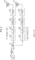
- Fig. 2 is a diagram illustrating an example of the configuration of the transmitter 120 of the communication apparatus 100.
- the transmitter 120 includes a MAC unit 101, a stream generator 102, encoders 103a and 103b, data modulators 104a and 104b, symbol block generators 105a and 105b, transmission front end (F/E) circuits 110a and 110b, and transmitting antennas 111a and 111b.
- a MAC unit 101 a stream generator 102, encoders 103a and 103b, data modulators 104a and 104b, symbol block generators 105a and 105b, transmission front end (F/E) circuits 110a and 110b, and transmitting antennas 111a and 111b.
- Nss represents the number of MIMO streams (Nss is an integer greater than or equal to 1).
- the communication apparatus 100 may include four encoders 103 in parallel.
- the communication apparatus 100 may include Nss encoders 103, Nss data modulators 104, Nss symbol block generators 105, Nss transmission F/E circuits 110, and Nss transmitting antennas 111.
- the MAC unit 101 generates transmission data and inputs the generated transmission data to the stream generator 102.
- the MAC unit 101 determines the transmission data size, the number of MIMO streams, the code rate of each stream, the LDPC codeword size of each stream, the modulation scheme of each stream, and the number of data symbols for each of symbol blocks and, thereafter, sends the determined information to the stream generator 102, the encoders 103a and 103b, the data modulators 104a and 104b, and the symbol block generators 105a and 105b.
- the stream generator 102 performs bit scrambling on the transmission data.
- the stream generator 102 generates two types of padding bits, that is, data padding and block padding, and performs bit scrambling.
- the stream generator 102 adds the data padding and block padding subjected to bit scrambling to the transmission data subjected to bit scrambling so as to generate transmission data with padding. Thereafter, the stream generator 102 divides the transmission data with padding into a first transmission stream and a second transmission stream. The stream generator 102 inputs the first transmission stream and the second transmission stream to the encoders 103a and 103b, respectively.
- the stream generator 102 distributes the data with padding to the transmission streams in accordance with at least one of the LDPC codeword size, the LDPC code rate, and the modulation scheme for each of the transmission streams.
- the stream generator 102 when performing LDPC encoding on each of the transmission streams, the stream generator 102 adds data padding so that the size of the distributed transmission stream matches the LDPC codeword size.
- the stream generator 102 when generating a symbol block in each of the transmission streams, the stream generator 102 adds block padding so that the size of the distributed transmission stream matches the symbol block size.
- the encoders 103a and 103b perform error correction coding on transmission data and data padding included in the transmission stream and output the results to the data modulators 104a and 104b, respectively.
- the encoders 103a and 103b may use an LDPC (Low Density Parity Check) code as an error correction code.
- LDPC Low Density Parity Check
- the encoders 103a and 103b output the block padding included in the transmission stream to the data modulator 104 without performing error correction encoding.
- the encoders 103a and 103b may perform error correction encoding on the block padding.
- the encoder 103 may add (additional) error check code and error correction code for transmission data and data padding included in the transmission stream.
- the data modulator 104 performs data modulation on the transmission stream encoded by the encoder 103 to generate transmission data symbols.
- the data modulator 104 may use, for example, one of ⁇ /2 shift BPSK (Binary Phase Shift Keying), ⁇ /2 shift QPSK (Quadrature Phase Shift Keying), ⁇ /2 shift 8PSK (8 point Phase Shift Keying), ⁇ /2 shift 16QAM(16 points Quadrature Amplitude Modulation), ⁇ /2 shift 64QAM(64 points QAM), and ⁇ /2 shift 64NUC (64 points Non-Uniform Constellation).
- BPSK Binary Phase Shift Keying
- QPSK Quadratture Phase Shift Keying
- ⁇ /2 shift 8PSK 8 point Phase Shift Keying
- 16QAM(16 points Quadrature Amplitude Modulation ⁇ /2 shift 64QAM(64 points QAM)
- ⁇ /2 shift 64NUC 64 points Non-Uniform Constellation
- the symbol block generator 105 divides the transmission data symbols generated by the data modulator 105 into segments each having a predetermined number of symbols (hereinafter referred to as "N SPB ”) and inserts a guard interval symbol (hereinafter referred to as a "GI") into every segment.
- N SPB is, for example, 448 symbols.
- a symbol sequence that is a combination of N SPB transmission data symbols and GIs is referred to as a symbol block.
- N SPB the number of symbols per symbol block
- N CB is an integer greater than or equal to 1
- channel bonding the number of symbols per symbol block may be determined as N SPB ⁇ N CB .
- N CB is called the number of channel bonding.
- the transmission F/E circuit 110 includes digital and analog filters, a D/A conversion (digital/analog conversion) circuit, and an RF (Radio Frequency) circuit. For this reason, the transmission F/E circuit may be referred to as a "filter-D/A conversion-RF circuit". As the digital filter, for example, an RRC (Root Raised Cosine) filter is used.
- the transmission F/E circuit 110 generates a signal (referred to as an RF signal) by performing filter processing, D/A conversion processing, RF signal conversion (up-conversion), and power amplification and inputs the RF signal to the transmitting antennas 111.
- the transmitting antenna 111 transmits the RF signal generated by the transmission F/E circuit 110 to another communication apparatus (for example, the communication apparatus 100a) in the form of a radio signal.
- Fig. 3 is a flowchart illustrating an example of the processing performed by the stream generator 102.
- the stream generator 102 calculates the group size and the number of groups and determines the number of data paddings and the number of block paddings. In this manner, even when at least one of the modulation scheme, code rate, and codeword size varies transmission stream by transmission stream, the number of paddings can be reduced. That is, the data throughput can be improved.
- the number of codewords that minimizes the number of padding bits can be calculated without restriction that the number of codewords is a multiple of N BPSC (i). In this way, the present embodiment can reduce the number of paddings.
- N BPSC (i SS ) represents the number of bits per constellation point in the i SS -th transmission stream.
- R(i SS ) represents the code rate of the LDPC code in the iss-th transmission stream.
- the symbol block generator 105a (corresponding to a first transmission stream, that is, iss of 1) performs ⁇ /2 shift BPSK modulation, the value of N BPSC (1) is 1.
- the symbol block generator 105a performs ⁇ /2 shift QPSK modulation
- the value of N BPSC (1) is 2.
- the symbol block generator 105a performs ⁇ /2 shift 8PSK modulation
- the value of N BPSC (1) is 3.
- the symbol block generator 105a performs ⁇ /2 shift 16QAM modulation the value of N BPSC (1) is 4.
- the symbol block generator 105a performs ⁇ /2 shift 64QAM or 64NUC modulation, the value of N BPSC (1) is 6.
- Equation (6) Length represents the size of transmission data (in octet).
- a value is obtained by multiplying the size of transmission data by 8 to convert the size into the number of bits (the numerator of Equation (6)). Thereafter, the obtained value is divided by the sum of the group sizes Ng(i SS ) of all the transmission streams (the denominator of Equation (6)). Finally, the result of the division is rounded up to an integer.
- the number of groups X is described in more detail below.
- the stream generator 102 temporarily determines that data of a maximum of X ⁇ Ng(i SS ) bits is distributed to each of the transmission streams and calculates the number of codewords that can include X ⁇ Ng(i SS ) bits. That is, since the number of bits included in one codeword is L CW (i SS ) ⁇ R(i SS ), the stream generator 102 divides X ⁇ Ng(i SS ) by L CW (i SS ) ⁇ R(i SS ) and rounds up the resultant value to an integer, as indicated by Equation (7). In this manner, the stream generator 102 calculates the number of codewords N CW (i SS ).
- N CW (i SS ) ⁇ L CW (i SS ) ⁇ R(i SS ) in Equation (8) indicates the number of bits included in the codewords equal in number to the number calculated for the transmission stream in step S1003. That is, as can be seen from Equation (8), the stream generator 102 subtracts a value obtained by converting the size of transmission data into the number of bits from the sum of the numbers of bits included in the number of codewords of all the transmission streams. In this way, the stream generator 102 calculates the number of data paddings (the number of bits) N DATA_PAD .
- step S1005 the stream generator 102 calculates the number of symbol blocks N BLKS on the basis of the following Equation (9). Furthermore, the stream generator 102 calculates the number of block paddings (the number of bits) N BLK_PAD (i SS ) for each of the transmission streams on the basis of the following Equation (10).
- N CW (i SS ) ⁇ L CW (i SS )/N BPSC (i SS ) represents the number of data symbols included in the codewords equal in number to the number calculated for the iss-th transmission stream in step S1003.
- the stream generator 102 divides the number of data symbols included in the codewords by the number of data symbols per symbol block N SPB ⁇ N CB on the basis of Equation (9). In this manner, the stream generator 102 calculates the number of symbol blocks necessary for the transmission stream.
- the stream generator 102 calculates the necessary number of symbol blocks for each of the transmission streams and defines the largest number of symbol blocks among the calculated numbers as the number N BLKS of symbol blocks of a transmission packet.
- the stream generator 102 subtracts the number of data symbols included in N CW (i SS ) codewords from the number of data symbols per N BLKS symbol blocks on the basis of Equation (10). In this way, the stream generator 102 calculates the number of block paddings (the number of bits) N BLK_PAD (i SS ) in the iss-th transmission stream.
- step S1006 the stream generator 102 generates transmission data with padding. That is, the stream generator 102 generates a bit sequence with the data padding and block padding calculated in the above-described manner.
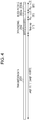
- Fig. 4 is a diagram illustrating an example of transmission data with padding generated by the stream generator 102 in step S1006. Step S1006 is described in detail below with reference to Fig. 4 .
- the stream generator 102 generates N DATA_PAD -bit data padding 2002 and appends the data padding 2002 to the transmission data 2001.
- the stream generator 102 generates N BLK_PAD (1)-bit block padding 2003a for the first transmission stream and appends the block padding 2003a to the data padding 2002.
- the stream generator 102 generates N BLK_PAD (2)-bit block padding 2003b for the second transmission stream and appends the block padding 2003b to the block padding 2003a. That is, the stream generator 102 sequentially adds N BLK_PAD (1)-bit to N BLK_PAD (N SS )-bit block padding 2003 in accordance with the number of streams Nss.
- the stream generator 102 may use a bit sequence consisting of bits 0 as the data padding 2002 and the block padding 2003. For example, the stream generator 102 appends, as the data padding 2002, N DATA_PAD bits 0 to the transmission data 2001 (that is, a bit sequence consisting of bits 0 and 1).
- the stream generator 102 performs bit scrambling on the transmission data with padding.
- the stream generator 102 may handle the transmission data 2001, the data padding 2002, and the block padding 2003 as a series of data without distinction. That is, the stream generator 102 need not initialize a scrambler at the head of the data padding 2002 and at the head of the block padding 2003.
- step S1008 the stream generator 102 divides the scrambled transmission data with padding into transmission streams and inputs the divided streams to the encoders 103a and 103b.
- Fig. 5 is a diagram illustrating an example of a stream dividing process performed by the stream generator 102. Step S1008 is described in detail below with reference to Fig. 5 .
- the stream generator 102 extracts Ng(1) bits from the transmission data 2001 and distributes the bits to the first transmission stream 2010a first (refer to #1-1 in Fig. 5 ). Subsequently, the stream generator 102 extracts Ng(2) bits from the transmission data 2001 and distributes the bits to the second transmission stream 2010b (refer to #1-2 in Fig. 5 ). The stream generator 102 repeats the process of sequentially distributing Ng(i SS ) bits to the first transmission stream through the N SS -th transmission stream at least "N SS ⁇ X" times (refer to #1-1 to #6-2 in Fig. 5 , and refer to Equation (6) for the value X).
- the stream generator 102 repeats the process of sequentially distributing Ng(i SS ) bits to each of the transmission streams "N SS ⁇ X" times. Subsequently, the stream generator 102 regards the transmission stream to which the number of bits corresponding to N CW (i SS ) codewords is distributed as a sign of completion. For example, in terms of the second transmission stream 2010b illustrated in Fig. 5 , the number of bits included in the distributed X groups (#1-2, #2-2, #3-2, #4-2, #5-2, #6-2) is equal to the number of bits corresponding to Ncw(iss) codewords (that is, N CW (i SS ) ⁇ L CW (i SS ) ⁇ R(i SS )). Accordingly, the stream generator 102 determines that allocation of group #6-2 is the sign of completion.
- the stream generator 102 After repeating the process N SS ⁇ X times, the stream generator 102 ends distribution to the completed transmission stream and continues distribution to the uncompleted transmission streams. For example, in Fig. 5 , the stream generator 102 ends the distribution to the second transmission stream 2010b after allocation of #6-2 and continues distribution to the first transmission stream 2010a. That is, the stream generator 102 distributes #7-1 and #8-1 to the first transmission stream 2010a. In other words, the stream generator 102 skips distribution to the already completed second transmission stream (for example, skips the distribution of #7-2 and #8-2) and continues the distribution process until the distribution of the data padding 2002 is completed.
- the stream generator 102 distributes the block padding 2003a and the block padding 2003b (refer to Fig. 5 ) to the transmission streams and inputs the transmission streams to the encoders 103a and 103b, respectively.
- the number of block paddings distributed to the iss-th transmission stream is N BLK_PAD (i SS ).
- the stream generator 102 distributes first N BLK_PAD (1) bits of the block padding (the block padding.2003a) to the first transmission stream and outputs the first transmission stream to the encoder 103a.
- the stream generator 102 distributes N BLK_PAD (2) bits following the block padding 2003a (the block padding 2003b) to the second transmission stream and outputs the second transmission stream to the encoder 103b.
- the stream generator 102 can increase the group size by using Equation (7), as compared with Equation (5). Furthermore, the transmission data with padding can be regularly distributed to the transmission streams (described in more detail later). In this way, a circuit scale can be reduced, and power consumption can be reduced.
- the stream generator 102 may replace the value 56 in Equation (7) with the value 52. In this manner, the stream generator 102 can regularly distribute the transmission data with padding to the transmission streams (described in more detail later). As a result, a circuit scale can be reduced, and power consumption can be reduced.
- the stream generator 102 may use Equation (7).
- the stream generator 102 may replace the value 56 in Equation (11) with the value 52.
- the stream generator 102 may use Equation (5).
- the stream generator 102 can reduce the number of data paddings in the first transmission stream by using Equation (12).
- the stream generator 102 can reduce the number of block paddings.
- L CW (i SS ) is the LDPC codeword size for the iss-th transmission stream. According to the 11ay standard, the value used for L CW (i SS ) is, for example, 624, 672, 1248, or 1344. L CW (1) represents the LDPC codeword size of the first transmission stream.
- the value of Y may be 16, 48, or Lcw(1).
- the communication apparatus 100 determines that the value of Y is 56 (equivalent to Equation (6)). As a result, if the value of L CW (i SS ) is, for example, 672 or 1344 and if the value of N BPSC (i SS ) is any one of 1, 2, 4 and 6, the above-described condition (the value of Y ⁇ N BPSC (i SS ) is a divisor of L CW (i SS )) is satisfied for any combination of L CW (i SS ) and N BPSC (i SS ).
- step S1008 the stream generator 102 can regularly distribute the transmission data with padding to the transmission stream without leaving a remainder of transmission bits less than the group size of the transmission stream. As a result, the circuit scale can be reduced, and power consumption can be reduced.
- Equation (5) provides a combination that does not satisfy the above-described condition (the value of Y ⁇ N BPSC (i SS ) is a divisor of L CW (i SS )).
- Y of 4 corresponds to such a case, and 672 is not divisible by 16 ⁇ 4.
- the transmission stream has unused transmission bits less than the group size.
- Equation (5) provides a combination that does not satisfy the above-described condition (the value of Y ⁇ N BPSC (i SS ) is a divisor of L CW (i SS )).
- N CW (i SS ) is greater than or equal to N CW (i SS ) calculated by Equation (7) and is an even number.
- the stream generator 102 can regularly distribute the transmission data with padding to the transmission streams without producing unused transmission bits less than the group size in the transmission stream in step S1008, even when ⁇ /2 shift 16QAM is used and the value of L CW (i SS ) is 624.
- the stream generator 102 determines the value of Y such that the value of Y ⁇ N BPSC (i SS ) is a divisor of L CW (i SS ) ⁇ 2.
- the stream generator 102 determines the value of Y ⁇ N BPSC (i SS ) so that the value of Y ⁇ N BPSC (i SS ) is a divisor of L CW (i SS ) ⁇ M(i SS ).
- the stream generator 102 can regularly distribute the transmission data with padding to the transmission streams without producing unused transmission bits less than the group size in the transmission stream.
- Equation (13) the group size increases and the number of groups X decreases in accordance with the value of Y. As a result, data transfer control is facilitated in distribution of the transmission data to the transmission streams, and the circuit scale can be reduced.
- a method is described below with reference to Figs. 6A , 6B , and 6C for preventing an increase in the number of codewords and the number of data paddings by using a small M(iss) value used for the value of Y.
- the stream generator 102 sets the value of M(i SS ) in Equation (15) to a value the same as the value of N BPSC (i SS ).
- the value of Y is determined to be a divisor of L CW (i SS ).
- the values of L CW (i SS ) include 672 and 624, the value of Y is set to 48 which is a common divisor of 672 and 624.
- the stream generator 102 may determine the value of M(i SS ) in accordance with the LDPC codeword size and the modulation scheme.
- Fig. 6A illustrates an example of the values of M(iss) when Y is 16.
- Fig. 6B illustrates an example of the values of M(i SS ) when Y is 48.
- Fig. 6C illustrates another example of the values of M(i SS ) when Y is 16 or 48.
- the column with header "L_CW(i_SS)” contains the codeword size L CW (i SS ).
- the column with header "modulation scheme” contains a data modulation scheme.
- the column with header "N_BPSC(i_SS)” contains the value of N BPSC (i SS ) corresponding to the data modulation scheme stored in the column with header "modulation scheme”.
- the column with header "M(i_SS)” contains an example of the value of M(iss) corresponding to the values stored in the column with header "L CW (i_SS)” and the column with header "N_BPSC(i_SS)".
- the stream generator 102 determines a combination of Y and M(i SS ) that satisfies the condition that the value of Y ⁇ N BPSC (i SS ) is a divisor of L CW (i SS ) ⁇ M(i SS ).
- the stream generator 102 refers to Fig. 6A , Fig. 6B , or Fig. 6C and selects, as M(i SS ), a small integer (for example, 1, 2, 3, 4, or 6) in accordance with the LDPC codeword size and the data modulation scheme. In this manner, the number of codewords calculated by Equation (15) can be reduced, and the number of data paddings can be reduced.
- M(i SS ) a small integer (for example, 1, 2, 3, 4, or 6) in accordance with the LDPC codeword size and the data modulation scheme.
- a large Y value (for example, 48) is used in Fig. 6B , as compared with that in Fig. 6A .
- the stream dividing process in step S1008 illustrated in Fig. 3 is simplified, and the circuit scale can be reduced.
- the number of transmission data is set to 284, the LDPC codeword size of the first transmission stream (L CW (1)) is set to 1344, the LDPC code rate (R(1)) is set to 3/4, and the modulation scheme is set to ⁇ /2 shift 64QAM (N BPSC (1) is 6).
- the LDPC codeword size of the second transmission stream (L CW (2)) is set to 672, the LDPC code rate (R(2)) is set to 13/16, and the modulation scheme is set to ⁇ /2 shift 16QAM (N BPSC (1) is 4).
- Equation (13) Y in Equation (13) is set to 56, and M(iss) in Equation (15) is set to 1.
- N SPB is set to 480
- N CB is set to 1.
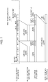
- Fig. 7 illustrates an example of the sequence of processes in which the encoder 103a performs LDPC coding on the first transmission stream, the data modulator 104a performs data modulation (for example, ⁇ /2 shift 64QAM), and the symbol block generator 105a adds a GI.
- the encoder 103a performs LDPC coding on the first transmission stream
- the data modulator 104a performs data modulation (for example, ⁇ /2 shift 64QAM)
- the symbol block generator 105a adds a GI.
- the number of transmission data is set to 284, the LDPC codeword size (L CW (1)) of the first transmission stream is set to 1344, and the LDPC code rate (R(1)) is set to 3/4, and the modulation scheme is set to ⁇ /2 shift 64QAM (N BPSC (1) is 6).
- the LDPC codeword size (L CW (2)) of the second transmission stream is set to 672, the LDPC code rate (R(2)) is set to 13/16, and the modulation scheme is set to ⁇ /2 shift 16QAM (N BPSC (1) is 4).
- group size Ng(1) is 252 bits, the sum of the sizes of the four groups (for example, #1-1, #2-1, #3-1, and #4-1) corresponds to LDPC data in one codeword.
- the encoder 103a Upon receiving, from the stream generator 102, data of bits corresponding to L CW (i SS ) ⁇ R(i SS ) ⁇ M(i SS )/Ng(i SS ) groups (for example, four groups, #1-1, #2-1, #3-1, and #4-1) in the first transmission stream 2010a, the encoder 103a regards the input data as M(i SS ) LDPC data (for example, the LDPC data 2020a, M(i SS ) is 1) and performs LDPC encoding on the M(i SS ) LDPC data. Thus, the encoder 103a generates parity bits (for example, parity 2021a).
- the encoder 103a every time the encoder 103a sequentially receives data of bits corresponding to L CW (i SS ) ⁇ R(i SS ) ⁇ M(i SS )/Ng(i SS ) groups (for example, #5-1, #6-1, #7-1, and #8-1), the encoder 103a performs LDPC encoding on the M(i SS ) LDPC codewords and generates parity bits (for example, parity 2021b).
- the encoder 103a does not perform the encoding process on the block padding 2003a.
- the encoder 103a appends the block padding 2003a not subjected to the encoding process to the encoded codeword (including the LDPC data 2020a, parity 2021a, LDPC data 2020b, and parity 2021b). Thereafter, the encoder 103a outputs the codeword to the data modulator 104a.
- the data modulator 104a performs data modulation (for example, ⁇ /2 shift 64QAM) on the LDPC data 2020a, parity 2021a, LDPC data 2020b, parity 2021b, and block padding 2003a and generates a symbol block 2030a.
- the data modulator 104a adds a GI (not illustrated) before the symbol block 2030a and adds a GI (a GI 2031a) after the symbol block 2030a to generate a transmission signal. Thereafter, the data modulator 104a outputs the generated transmission signal to the transmission F/E circuit 110a.
- the stream generator 102 calculates the number of groups X common to the transmission streams by using Equation (6).
- the number of groups X may be calculated as a value X(i SS ) that varies transmission stream by transmission stream.
- Equation (16) is a recurrence equation that sequentially calculates X(i SS ) (iss is 1 to N SS ). That is, X(1) of the first transmission stream is calculated and, subsequently, X(2) of the second transmission stream, and so on.
- X(i SS ) of the i SS -th transmission stream is calculated as follows:
- the stream generator 102 of the communication apparatus 100 calculates the group size Ng(i SS ) and the number of groups X and, thereafter, determines the number of data paddings and the number of block paddings on the basis of Ng(i SS ) and X.
- the number of paddings can be reduced, data throughput can be increased, and the radio transmission efficiency can be increased.
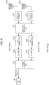
- Fig. 8 is a diagram illustrating an example of the configuration of the receiving unit 130 of the communication apparatus 100.
- the receiving unit 130 includes a MAC unit 201, a stream combining unit 202, decoders 203a and 203b, data demodulators 204a and 204b, a MIMO signal separation unit 205, reception front end (F/E) circuits 210a and 210b, and receiving antennas 211a and 211b.
- a MAC unit 201 a stream combining unit 202, decoders 203a and 203b, data demodulators 204a and 204b, a MIMO signal separation unit 205, reception front end (F/E) circuits 210a and 210b, and receiving antennas 211a and 211b.
- F/E reception front end
- the receiving unit 130 is further applicable to the case where the number of MIMO streams is 1 or 2 or more and, thus, description of the case where the number of MIMO streams is not 2 is not given here.
- the receiving antennas 211a and 211b receive a MIMO radio signal (an RF signal) from another communication apparatus (for example, the communication apparatus 100).
- a MIMO radio signal an RF signal
- Each of the reception F/E circuits 210a and 210b includes digital and analog filters, an A/D conversion (analog/digital conversion) circuit, and an RF (Radio Frequency) circuit.
- the reception F/E circuit may be referred to as a "filter-A/D conversion-RF circuit".
- the digital filter for example, an RRC (Root Raised Cosine) filter is used.
- the reception F/E circuits 210a and 210b perform power amplification, conversion to a baseband signal (down convert), A/D conversion processing, and filter processing on the RF signals received by the receiving antennas 211a and 211b.
- the MIMO signal separation unit 205 performs a MIMO signal separation process on the baseband signals (the MIMO signals) output from the reception F/E circuits 210a and 210b and reproduces the modulated signals of the first and second streams.
- the MIMO signal separation unit 205 may include a timing synchronization circuit, a frequency synchronization circuit, a channel estimation circuit, and an equalization circuit.
- the data demodulators 204a and 204b convert the ⁇ /2-BSPK modulation signals included in the reproduced first and second streams into bit likelihood information.
- the decoders 203a and 203b perform error correction (LDPC) decoding and error detection (CRC) from the bit likelihood information sequences of the first and second streams and generate received bits.
- LDPC error correction
- CRC error detection
- the stream combining unit 202 collects the received bit signals of the first and second streams into a received data sequence and outputs the received data sequence to the MAC unit 201.
- the communication apparatuses 100 and 100a can be used in a cellular phone, a smartphone, a tablet terminal, and a television set that transmit a moving image, a still image, text data, audio/speech data, or control data.
- LSI LSI
- IC system LSI
- super LSI ultra LSI
- circuit integration is not limited to LSI and may be achieved by dedicated circuitry or a general-purpose processor other than an LSI.
- a field programmable gate array (FPGA) which is programmable after fabrication of the LSI, or a reconfigurable processor which allows reconfiguration of connections and settings of circuit cells in LSI may be used.
- the present disclosure is suitable for a transmission apparatus, a transmission method, a reception apparatus, and a reception method that perform communication using a multi-antenna.
Landscapes
- Engineering & Computer Science (AREA)
- Computer Networks & Wireless Communication (AREA)
- Signal Processing (AREA)
- Quality & Reliability (AREA)
- Physics & Mathematics (AREA)
- Probability & Statistics with Applications (AREA)
- Theoretical Computer Science (AREA)
- Radio Transmission System (AREA)
- Mobile Radio Communication Systems (AREA)
- Vehicle Body Suspensions (AREA)
- Digital Transmission Methods That Use Modulated Carrier Waves (AREA)
Abstract
Description
- The present disclosure relates to a transmission apparatus and a transmission method.
- The IEEE 802.11ay standard (referred to as the "11ay standard") has been developed as a technique for achieving high-speed data transmission. In 11ay standard, the MIMO technique is applied to millimeter wave communication (refer to NPL 1).
- NPL 1 describes one of techniques for dividing transmission data input from MAC into streams. In
NPL 1, bits (M_bits(i)) proportional to the code rate (R(i)) and the number of bits per modulation symbol (NBPSC(i)) are sequentially distributed to each of streams. - NPL 1: IEEE 802.11-17/0211r1
- However, in
NPL 1, study is insufficient to cope with an increase in the number of padding bits when the modulation scheme, code rate, and codeword size vary stream by stream. - The non-limiting example of the present disclosure provides a transmission apparatus and a transmission method capable of reducing the number of padding bits when at least one of the modulation scheme, the code rate, and the codeword size varies stream by stream.
- According to one aspect, a transmission apparatus includes a stream generator that determines a size of padding data to be added to transmission data by using a group size of each of a plurality of transmission streams calculated on the basis of a code rate and a modulation scheme that are set for each transmission stream and the number of groups calculated from a size of the transmission data and the group size of the each transmission data, adds padding data having the determined size to the transmission data, and distributes the transmission data and the padding data to generate the plurality of transmission streams, an encoder that encodes each of the generated transmission streams with the code rate set for the transmission stream, a modulator that modulates each of the encoded transmission streams by using the modulation scheme set for the each transmission stream, and a radio transmitter that converts the modulated transmission streams into radio signals and transmits the radio signals from a plurality of transmitting antennas.
- It should be noted that general or specific embodiments may be implemented as an apparatus, a method, an integrated circuit, a computer program, a storage medium, or any selective combination of a system, an integrated circuit, a computer program, and a storage medium.
- According to an aspect of the present disclosure, the number of padding bits can be reduced when at least one of the modulation scheme, the code rate, and the codeword size varies stream by stream.
-
- [
Fig. 1] Fig. 1 is a diagram illustrating an example of the configuration of a MIMO communication system according to the present embodiment. - [
Fig. 2] Fig. 2 is a diagram illustrating an example of the configuration of a transmitter in a communication apparatus according to the present embodiment. - [
Fig. 3] Fig. 3 is a flowchart illustrating an example of the processing performed by a stream generator according to the present embodiment. - [
Fig. 4] Fig. 4 is a diagram illustrating an example of transmission data with padding according to the present embodiment. - [
Fig. 5] Fig. 5 is a diagram illustrating an example of stream dividing processing according to the present embodiment. - [
Fig. 6A] Fig. 6A is a diagram illustrating an example of the value of M(iss) when Y is 16 according to the present embodiment. - [
Fig. 6B] Fig. 6B is a diagram illustrating an example of the value of M(iss) when Y is 48 according to the present embodiment. - [
Fig. 6C] Fig. 6C is a diagram illustrating another example of the value of M(iss) when Y is 16 or 48 according to the present embodiment. - [
Fig. 7] Fig. 7 is a diagram illustrating an example in which LDPC encoding, data modulation, and GI addition are performed on a transmission stream according to the present embodiment. - [
Fig. 8] Fig. 8 is a diagram illustrating an example of the configuration of a receiving unit in the communication apparatus according to the present embodiment. - Embodiments of the present disclosure is described in detail below with reference to the accompanying drawings as appropriate. Note that too much description may be avoided. For example, detailed descriptions of already well-known matters and repeated descriptions for substantially the same configuration may be omitted. This is to avoid the following description from becoming unnecessarily redundant and to aid those skilled in the art in understanding the present invention.
- The accompanying drawings and the following description are provided to enable those skilled in the art to fully understand the present disclosure and are not intended to limit the subject matter set forth in the appended claims.
- In the case of distinguishing between elements of the same type in the description below, the reference numerals are used as follows: "
encoder 103a" and "encoder 103b". However, in the case where distinction is not needed in the description, only common part of the reference numerals may be used (e.g., "encoder 103"). - In the following description, the notation "XYZ unit" used for a constituent element of communication apparatuses 100 and 100a and a
transmitter 120 may be replaced by another notation, such as "XYZ circuit (circuitry)", "XYZ apparatus", or "XYZ module". - For example, in
NPL 1, asymbol block generator 105a sets NBPSC(i) to 1 when performing π/2 shift BPSK modulation, sets NBPSC(i) to 2 when performing π/2 shift QPSK modulation, sets NBPSC(i) to 4 when performing π/2 shift 16QAM modulation, and sets NBPSC(i) to 6 when performing π/2 shift 64QAM or 64NUC modulation. - The following equation (1) is an example of a mathematical expression for calculating M_bits(i):
[Formula 1]
- In Equation (1), i (i is an integer greater than or equal to 0) represents a stream number, and R(i) represents a code rate. In Equation (1), M_bits(i) is adjusted to an integer by multiplying the code rate R(i), which is a fraction, by 16 (× 16).
- The following Equation (2) is an example of an equation for calculating N_bits(i) indicating the number of bits distributed to the i-th stream on the basis of the codeword size:
[Formula 2]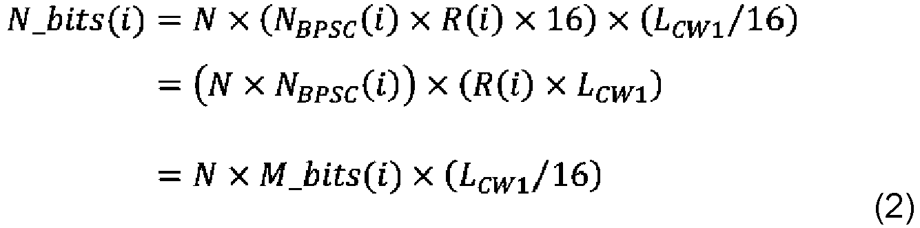
- In Equation (2), LCW1 represents a codeword size. N is a variable that is determined so that the sum of the number of bits of each of all the streams is greater than or equal to the number of transmission bits. That is, N is a variable that is determined so that a value obtained by summing N_bits(i) for all the streams is greater than or equal to a value obtained by summing M_bits(i) for all the streams. Note that if the sum of N_bits(i) is greater than the number of transmission bits, the bits corresponding to the difference are filled up with padding bits.
- The second line of Equation (2) is an expression obtained by modifying the first line. "R(i) × LCW1" represents the number of transmission bits (the number of information bits) per codeword. Thus, the second line of Equation (2) indicates that N_bits(i) includes "N × NBPSC(i)" codewords. That is, N is a variable used to determine the number of codewords in each stream.
- The third line of Equation (2) is an expression obtained by substituting Equation (1) for the first line of Equation (2). As can be seen from the third line of Equation (2), the process of allocating transmission data bits to each stream is performed in the manner described below. That is, the process of allocating M_bits(i) bits to the i-th stream is defined as a single process. The single process is repeated "N × LCW1/16" times. In this manner, N_bits(i) is allocated to the i-th stream in total. After the bit allocation process is repeated "N × LCW1/16" times and, thus, all of the transmission data bits are distributed, padding bits are distributed to each of the streams.
- The number of symbols in the stream is calculated by dividing N_bits(i) by NBPSC(i) × R(i). For this reason, Equation (2) is a calculation equation that makes the numbers of symbols in the streams the same.
- In addition, the number of codewords NCW(i) in the i-th stream is calculated by dividing N_bits(i) by LCW × R(i). Therefore, NCW(i) is calculated by the following equation (3):
[Formula 3]
- For example, in the case of π/2 shift 16QAM modulation, since NBPSC(i) is 4, the number of codewords NCW(i) is a multiple of 4 from Equation (3). Note that NCW(i) calculated by Equation (3) is a multiple of NBPSC(i). For example, if NCW- min(i) that minimizes the number of padding bits is a value other than a multiple of 4 (for example, NCW-min(i) = 37), NCW(i) is a value rounded up to a multiple of 4 (for example, Ncw(i) = 40).
- That is, NCW(i) calculated by Equation (2) and Equation (3) may be greater than NCW(i) that minimizes the number of padding bits. That is, the number of padding bits may increase. It is difficult to calculate NCW(i) that minimizes the number of padding bits by using Equation (2) and Equation (3).
- For this reason, according to the technique described in
NPL 1, if the modulation multi-level number NBPSC(i) is large, the number of padding bits may increase, and an unnecessary signal may be transmitted. - Furthermore, when a codeword size LCW(i) that varies stream by stream is applied, the following Equation (4) is used instead of Equation (2):
[Formula 4]
- N(i) is a variable that is determined such that the sum of bits of all the streams is greater than or equal to the number of transmission bits. However, unlike Equation (2), according to Equation (4), the codeword size varies stream by stream. Accordingly, the equation for calculating the set of N(i) values that minimizes the number of paddings needs to be determined in accordance with the set of codeword sizes. Thus, the amount of calculation increases.
-
Fig. 1 is a diagram illustrating an example of the configuration of a MIMO communication system. - The
transmitter 120 of the communication apparatus 100 includes a plurality of transmitting antennas. Thetransmitter 120 transmits different transmission data from the transmitting antennas at the same transmission slot timing (the same sampling timing in a D/A converter). A receivingunit 130 of the communication apparatus 100a, which is a communication partner, includes a plurality of receiving antennas, which receive reception data at the same receiving slot timing (the same sampling timing in an A/D converter). At this time, the channel delays are different. For this reason, transmission data transmitted by thetransmitter 120 in the same transmission slot are not always received by the receivingunit 130 in the same reception slot. Note that n represents a transmission slot number and a reception slot number. k represents a frequency subcarrier number. -
Fig. 2 is a diagram illustrating an example of the configuration of thetransmitter 120 of the communication apparatus 100. - The
transmitter 120 includes aMAC unit 101, astream generator 102,encoders data modulators symbol block generators circuits antennas - According to the first embodiment, a case where the number of MIMO streams is 2 is described. However, the first embodiment is also applicable to the case where the number of MIMO streams is 1 or 2 or more. In the description below, Nss represents the number of MIMO streams (Nss is an integer greater than or equal to 1).
- For example, when the number of MIMO streams is 4, the communication apparatus 100 may include four encoders 103 in parallel. Similarly, when performing MIMO transmission of Nss streams, the communication apparatus 100 may include Nss encoders 103, Nss data modulators 104, Nss symbol block generators 105, Nss transmission F/E circuits 110, and Nss transmitting antennas 111.
- The
MAC unit 101 generates transmission data and inputs the generated transmission data to thestream generator 102. In addition, theMAC unit 101 determines the transmission data size, the number of MIMO streams, the code rate of each stream, the LDPC codeword size of each stream, the modulation scheme of each stream, and the number of data symbols for each of symbol blocks and, thereafter, sends the determined information to thestream generator 102, theencoders data modulators symbol block generators - The
stream generator 102 performs bit scrambling on the transmission data. In addition, thestream generator 102 generates two types of padding bits, that is, data padding and block padding, and performs bit scrambling. - Subsequently, the
stream generator 102 adds the data padding and block padding subjected to bit scrambling to the transmission data subjected to bit scrambling so as to generate transmission data with padding. Thereafter, thestream generator 102 divides the transmission data with padding into a first transmission stream and a second transmission stream. Thestream generator 102 inputs the first transmission stream and the second transmission stream to theencoders - Note that the
stream generator 102 distributes the data with padding to the transmission streams in accordance with at least one of the LDPC codeword size, the LDPC code rate, and the modulation scheme for each of the transmission streams. - Furthermore, when performing LDPC encoding on each of the transmission streams, the
stream generator 102 adds data padding so that the size of the distributed transmission stream matches the LDPC codeword size. - In addition, when generating a symbol block in each of the transmission streams, the
stream generator 102 adds block padding so that the size of the distributed transmission stream matches the symbol block size. - The
encoders encoders - In addition, the
encoders encoders - The data modulator 104 performs data modulation on the transmission stream encoded by the encoder 103 to generate transmission data symbols. As the data modulation scheme, the data modulator 104 may use, for example, one of π/2 shift BPSK (Binary Phase Shift Keying), π/2 shift QPSK (Quadrature Phase Shift Keying), π/2 shift 8PSK (8 point Phase Shift Keying), π/2 shift 16QAM(16 points Quadrature Amplitude Modulation), π/2 shift 64QAM(64 points QAM), and π/2 shift 64NUC (64 points Non-Uniform Constellation). Note that the transmission stream encoded by the encoder 103 includes distributed transmission data, data padding, and block padding, as described above.
- The symbol block generator 105 divides the transmission data symbols generated by the data modulator 105 into segments each having a predetermined number of symbols (hereinafter referred to as "NSPB") and inserts a guard interval symbol (hereinafter referred to as a "GI") into every segment. NSPB is, for example, 448 symbols. A symbol sequence that is a combination of NSPB transmission data symbols and GIs is referred to as a symbol block.
- Note that in the case of transmission using a 2.16-GHz channel, the number of symbols per symbol block may be determined as NSPB. In the case of transmission using 2.16 × NCB-GHz (NCB is an integer greater than or equal to 1) channel (referred to as channel bonding), the number of symbols per symbol block may be determined as NSPB × NCB. NCB is called the number of channel bonding.
- The transmission F/E circuit 110 includes digital and analog filters, a D/A conversion (digital/analog conversion) circuit, and an RF (Radio Frequency) circuit. For this reason, the transmission F/E circuit may be referred to as a "filter-D/A conversion-RF circuit". As the digital filter, for example, an RRC (Root Raised Cosine) filter is used. The transmission F/E circuit 110 generates a signal (referred to as an RF signal) by performing filter processing, D/A conversion processing, RF signal conversion (up-conversion), and power amplification and inputs the RF signal to the transmitting antennas 111.
- The transmitting antenna 111 transmits the RF signal generated by the transmission F/E circuit 110 to another communication apparatus (for example, the communication apparatus 100a) in the form of a radio signal.
-
Fig. 3 is a flowchart illustrating an example of the processing performed by thestream generator 102. - In the processing illustrated in
Fig. 3 , thestream generator 102 calculates the group size and the number of groups and determines the number of data paddings and the number of block paddings. In this manner, even when at least one of the modulation scheme, code rate, and codeword size varies transmission stream by transmission stream, the number of paddings can be reduced. That is, the data throughput can be improved. - As compared with the technique described in NPL 1 (refer to Equation (3)) that calculates the number of codewords in each transmission stream by using the variable N, according to the present embodiment, the number of codewords that minimizes the number of padding bits can be calculated without restriction that the number of codewords is a multiple of NBPSC(i). In this way, the present embodiment can reduce the number of paddings.
- The processing performed in
Fig. 3 is described below. - In step S1001, the
stream generator 102 calculates a group size Ng(iSS) for each of transmission streams on the basis of the following Equation (5):
[Formula 5]
- In Equation (5), NBPSC(iSS) represents the number of bits per constellation point in the iSS-th transmission stream. R(iSS) represents the code rate of the LDPC code in the iss-th transmission stream.
- For example, when the
symbol block generator 105a (corresponding to a first transmission stream, that is, iss of 1) performs π/2 shift BPSK modulation, the value of NBPSC(1) is 1. When thesymbol block generator 105a performs π/2 shift QPSK modulation, the value of NBPSC(1) is 2. When thesymbol block generator 105a performs π/2 shift 8PSK modulation, the value of NBPSC(1) is 3. When thesymbol block generator 105a performs π/2 shift 16QAM modulation, the value of NBPSC(1) is 4. When thesymbol block generator 105a performs π/2 shift 64QAM or 64NUC modulation, the value of NBPSC(1) is 6. - In step S1002, the
stream generator 102 calculates the number of groups X on the basis of the following Equation (6):
[Formula 6]
- In Equation (6), Length represents the size of transmission data (in octet). As can be seen from Equation (6), to obtain the number of groups X, a value is obtained by multiplying the size of transmission data by 8 to convert the size into the number of bits (the numerator of Equation (6)). Thereafter, the obtained value is divided by the sum of the group sizes Ng(iSS) of all the transmission streams (the denominator of Equation (6)). Finally, the result of the division is rounded up to an integer. The number of groups X is described in more detail below.
- In step S1003, the
stream generator 102 calculates the number of codewords NCW(iSS) for each of the transmission streams on the basis of the following Equation (7):
[Formula 7]
- The
stream generator 102 temporarily determines that data of a maximum of X × Ng(iSS) bits is distributed to each of the transmission streams and calculates the number of codewords that can include X × Ng(iSS) bits. That is, since the number of bits included in one codeword is LCW(iSS) × R(iSS), thestream generator 102 divides X × Ng(iSS) by LCW(iSS) × R(iSS) and rounds up the resultant value to an integer, as indicated by Equation (7). In this manner, thestream generator 102 calculates the number of codewords NCW(iSS). - In step S1004, the
stream generator 102 calculates the number of data paddings (number of bits) NDATA_PAD on the basis of the following Equation (8):
[Formula 8]
- NCW(iSS) × LCW(iSS) × R(iSS) in Equation (8) indicates the number of bits included in the codewords equal in number to the number calculated for the transmission stream in step S1003. That is, as can be seen from Equation (8), the
stream generator 102 subtracts a value obtained by converting the size of transmission data into the number of bits from the sum of the numbers of bits included in the number of codewords of all the transmission streams. In this way, thestream generator 102 calculates the number of data paddings (the number of bits) NDATA_PAD. - In step S1005, the
stream generator 102 calculates the number of symbol blocks NBLKS on the basis of the following Equation (9). Furthermore, thestream generator 102 calculates the number of block paddings (the number of bits) NBLK_PAD(iSS) for each of the transmission streams on the basis of the following Equation (10).
[Formula 9]

- In Equation (9), NCW(iSS) × LCW(iSS)/NBPSC(iSS) represents the number of data symbols included in the codewords equal in number to the number calculated for the iss-th transmission stream in step S1003. The
stream generator 102 divides the number of data symbols included in the codewords by the number of data symbols per symbol block NSPB × NCB on the basis of Equation (9). In this manner, thestream generator 102 calculates the number of symbol blocks necessary for the transmission stream. Thestream generator 102 calculates the necessary number of symbol blocks for each of the transmission streams and defines the largest number of symbol blocks among the calculated numbers as the number NBLKS of symbol blocks of a transmission packet. - The
stream generator 102 subtracts the number of data symbols included in NCW(iSS) codewords from the number of data symbols per NBLKS symbol blocks on the basis of Equation (10). In this way, thestream generator 102 calculates the number of block paddings (the number of bits) NBLK_PAD(iSS) in the iss-th transmission stream. - In step S1006, the
stream generator 102 generates transmission data with padding. That is, thestream generator 102 generates a bit sequence with the data padding and block padding calculated in the above-described manner. -
Fig. 4 is a diagram illustrating an example of transmission data with padding generated by thestream generator 102 in step S1006. Step S1006 is described in detail below with reference toFig. 4 . - The
stream generator 102 generates NDATA_PAD-bit data padding 2002 and appends the data padding 2002 to thetransmission data 2001. In addition, thestream generator 102 generates NBLK_PAD(1)-bit block padding 2003a for the first transmission stream and appends theblock padding 2003a to thedata padding 2002. Furthermore, thestream generator 102 generates NBLK_PAD(2)-bit block padding 2003b for the second transmission stream and appends theblock padding 2003b to theblock padding 2003a. That is, thestream generator 102 sequentially adds NBLK_PAD(1)-bit to NBLK_PAD(NSS)-bit block padding 2003 in accordance with the number of streams Nss. - Note that the
stream generator 102 may use a bit sequence consisting of bits 0 as thedata padding 2002 and the block padding 2003. For example, thestream generator 102 appends, as thedata padding 2002, NDATA_PAD bits 0 to the transmission data 2001 (that is, a bit sequence consisting of bits 0 and 1). - Referring back to
Fig. 3 , in step S1007, thestream generator 102 performs bit scrambling on the transmission data with padding. To perform the bit scrambling, thestream generator 102 may handle thetransmission data 2001, thedata padding 2002, and the block padding 2003 as a series of data without distinction. That is, thestream generator 102 need not initialize a scrambler at the head of the data padding 2002 and at the head of the block padding 2003. - In step S1008, the
stream generator 102 divides the scrambled transmission data with padding into transmission streams and inputs the divided streams to theencoders -
Fig. 5 is a diagram illustrating an example of a stream dividing process performed by thestream generator 102. Step S1008 is described in detail below with reference toFig. 5 . - The
stream generator 102 extracts Ng(1) bits from thetransmission data 2001 and distributes the bits to thefirst transmission stream 2010a first (refer to #1-1 inFig. 5 ). Subsequently, thestream generator 102 extracts Ng(2) bits from thetransmission data 2001 and distributes the bits to thesecond transmission stream 2010b (refer to #1-2 inFig. 5 ). Thestream generator 102 repeats the process of sequentially distributing Ng(iSS) bits to the first transmission stream through the NSS-th transmission stream at least "NSS × X" times (refer to #1-1 to #6-2 inFig. 5 , and refer to Equation (6) for the value X). - The
stream generator 102 repeats the process of sequentially distributing Ng(iSS) bits to each of the transmission streams "NSS × X" times. Subsequently, thestream generator 102 regards the transmission stream to which the number of bits corresponding to NCW(iSS) codewords is distributed as a sign of completion. For example, in terms of thesecond transmission stream 2010b illustrated inFig. 5 , the number of bits included in the distributed X groups (#1-2, #2-2, #3-2, #4-2, #5-2, #6-2) is equal to the number of bits corresponding to Ncw(iss) codewords (that is, NCW(iSS) × LCW(iSS) × R(iSS)). Accordingly, thestream generator 102 determines that allocation of group #6-2 is the sign of completion. - After repeating the process NSS × X times, the
stream generator 102 ends distribution to the completed transmission stream and continues distribution to the uncompleted transmission streams. For example, inFig. 5 , thestream generator 102 ends the distribution to thesecond transmission stream 2010b after allocation of #6-2 and continues distribution to thefirst transmission stream 2010a. That is, thestream generator 102 distributes #7-1 and #8-1 to thefirst transmission stream 2010a. In other words, thestream generator 102 skips distribution to the already completed second transmission stream (for example, skips the distribution of #7-2 and #8-2) and continues the distribution process until the distribution of the data padding 2002 is completed. - Referring back to
Fig. 3 , in step S1009, thestream generator 102 distributes theblock padding 2003a and theblock padding 2003b (refer toFig. 5 ) to the transmission streams and inputs the transmission streams to theencoders stream generator 102 distributes first NBLK_PAD(1) bits of the block padding (the block padding.2003a) to the first transmission stream and outputs the first transmission stream to theencoder 103a. In addition, thestream generator 102 distributes NBLK_PAD(2) bits following theblock padding 2003a (theblock padding 2003b) to the second transmission stream and outputs the second transmission stream to theencoder 103b. - In step S1001, the
stream generator 102 may use the following Equation (11), instead of using Equation (5):
[Formula 11]
- When the value of Lcw(iss) is 672 or 1344, the
stream generator 102 can increase the group size by using Equation (7), as compared with Equation (5). Furthermore, the transmission data with padding can be regularly distributed to the transmission streams (described in more detail later). In this way, a circuit scale can be reduced, and power consumption can be reduced. - When the value of LCW(iSS) is 624 or 1248, the
stream generator 102 may replace the value 56 in Equation (7) with thevalue 52. In this manner, thestream generator 102 can regularly distribute the transmission data with padding to the transmission streams (described in more detail later). As a result, a circuit scale can be reduced, and power consumption can be reduced. - When the value of LCW(iSS) is 672 or 1344, the
stream generator 102 may use Equation (7). When the value of LCW(iSS) is 624 or 1248, thestream generator 102 may replace the value 56 in Equation (11) with thevalue 52. When the values of LCW(iSS) include 624, 672, 1248, and 1344, thestream generator 102 may use Equation (5). - In step S1001, the
stream generator 102 may use the following Equation (12), instead of using Equation (5):
[Formula 12]
- The
stream generator 102 can reduce the number of data paddings in the first transmission stream by using Equation (12). When the value of LCW(iSS) is 672 or 1344 or when the value of LCW(iSS) is 624 or 1248 (that is, when the values of LCW(iSS) include either 672 or 624 and when the values of LCW(iSS) include either 1344 or 1248), thestream generator 102 can reduce the number of block paddings. - In Equation (7), LCW(iSS) is the LDPC codeword size for the iss-th transmission stream. According to the 11ay standard, the value used for LCW(iSS) is, for example, 624, 672, 1248, or 1344. LCW(1) represents the LDPC codeword size of the first transmission stream.
- In step S1001, the
stream generator 102 may use the following Equation (13), instead of using Equation (5):
[Formula 13]
- In Equation (13), the value of Y may be 16, 48, or Lcw(1). Alternatively, the
stream generator 102 may determine the value of Y such that the value of Y × NBPSC(iSS) is a divisor of LCW(iSS). For example, when LCW(1) is 672 and the value of NBPSC(iSS) is 4, thestream generator 102 may set the value of Y in Equation (13) to any one of the divisors of 168 (= LCW(iSS)/NBPSC(iSS) = 672/4) (for example, 26). - The communication apparatus 100 determines that the value of Y is 56 (equivalent to Equation (6)). As a result, if the value of LCW(iSS) is, for example, 672 or 1344 and if the value of NBPSC(iSS) is any one of 1, 2, 4 and 6, the above-described condition (the value of Y × NBPSC(iSS) is a divisor of LCW(iSS)) is satisfied for any combination of LCW(iSS) and NBPSC(iSS).
- By determining the value of Y in Equation (13) such that the value of Y × NBPSC(iSS) is a divisor of LCW(iSS), an integer multiple of the group size is the same as the number of bits of one codeword. Accordingly, in step S1008, the
stream generator 102 can regularly distribute the transmission data with padding to the transmission stream without leaving a remainder of transmission bits less than the group size of the transmission stream. As a result, the circuit scale can be reduced, and power consumption can be reduced. - For example, when LCW(1) is 672 and the value of NBPSC(iSS) is 4 (corresponding to π/2 shift 16QAM), Equation (5) provides a combination that does not satisfy the above-described condition (the value of Y × NBPSC(iSS) is a divisor of LCW(iSS)). For example, Y of 4 corresponds to such a case, and 672 is not divisible by 16 × 4. For this reason, when distribution of the transmission data to the transmission stream is performed in step S1008, the transmission stream has unused transmission bits less than the group size.
- Furthermore, for example, when LCW(1) is 624 and the value of NBPSC(iSS) is 6 (corresponding to π/2 shift 64QAM), Equation (5) provides a combination that does not satisfy the above-described condition (the value of Y × NBPSC(iSS) is a divisor of LCW(iSS)).
- To regularly distribute the transmission data to the transmission streams, when the value of NBPSC(iSS) is 4 (corresponding to π/2 shift 16QAM) and the LCW(iSS) value is 624, the
stream generator 102 may calculate the number of codewords NCW(iSS) by using the following equation (14), instead of using Equation (7):
[Formula 14]
- In Equation (14), NCW(iSS) is greater than or equal to NCW(iSS) calculated by Equation (7) and is an even number. By using Equation (14), the
stream generator 102 can regularly distribute the transmission data with padding to the transmission streams without producing unused transmission bits less than the group size in the transmission stream in step S1008, even when π/2 shift 16QAM is used and the value of LCW(iSS) is 624. - When using Equation (14), the
stream generator 102 determines the value of Y such that the value of Y × NBPSC(iSS) is a divisor of LCW(iSS) × 2. - To satisfy the condition that the number of codewords NCW(iSS) is a multiple of M(iSS), the
stream generator 102 may calculate the number of codewords NCW(iSS) by using the following Equation (15) instead of using Equation (10):
[Formula 15]
- When using Equation (15), the
stream generator 102 determines the value of Y × NBPSC(iSS) so that the value of Y × NBPSC(iSS) is a divisor of LCW(iSS) × M(iSS). Thus, in step S1008, thestream generator 102 can regularly distribute the transmission data with padding to the transmission streams without producing unused transmission bits less than the group size in the transmission stream. - Furthermore, by using Equation (13), the group size increases and the number of groups X decreases in accordance with the value of Y. As a result, data transfer control is facilitated in distribution of the transmission data to the transmission streams, and the circuit scale can be reduced.
- However, in some cases, if the value of Y is increased, the number of codewords calculated by Equation (15) increases and, thus, the number of data paddings increases. As a result, the transmission data rate may decrease and, thus, the radio transmission efficiency may decrease.
- A method is described below with reference to
Figs. 6A ,6B , and6C for preventing an increase in the number of codewords and the number of data paddings by using a small M(iss) value used for the value of Y. - For example, the
stream generator 102 sets the value of M(iSS) in Equation (15) to a value the same as the value of NBPSC(iSS). In this case, the value of Y is determined to be a divisor of LCW(iSS). For example, if the values of LCW(iSS) include 672 and 624, the value of Y is set to 48 which is a common divisor of 672 and 624. - Alternatively, the
stream generator 102 may determine the value of M(iSS) in accordance with the LDPC codeword size and the modulation scheme.Fig. 6A illustrates an example of the values of M(iss) when Y is 16.Fig. 6B illustrates an example of the values of M(iSS) when Y is 48.Fig. 6C illustrates another example of the values of M(iSS) when Y is 16 or 48. - In
Fig. 6A ,Fig. 6B , andFig. 6C , the column with header "L_CW(i_SS)" contains the codeword size LCW(iSS). The column with header "modulation scheme" contains a data modulation scheme. The column with header "N_BPSC(i_SS)" contains the value of NBPSC(iSS) corresponding to the data modulation scheme stored in the column with header "modulation scheme". The column with header "M(i_SS)" contains an example of the value of M(iss) corresponding to the values stored in the column with header "LCW(i_SS)" and the column with header "N_BPSC(i_SS)". As an example, the column with header "Ng(i_SS) (when R = 13/16)" contains an example of the value of Ng(iss) corresponding to the values stored in the column with header "LCW(i_SS)" and the column with header "N_BPSC(i_SS) when the code rate is 13/16. Note that when the data modulation scheme is π/2 shift 8PSK, thecode rate 13/16 is not defined. For this reason, the value of Ng(iSS) when the code rate is 5/6 is displayed. - The
stream generator 102 determines a combination of Y and M(iSS) that satisfies the condition that the value of Y × NBPSC(iSS) is a divisor of LCW(iSS) × M(iSS). - A specific example illustrated in
Fig. 6A is described below. When LCW(iSS) is 624 and the modulation scheme is π/2 shift BPSK, NBPSC(iSS) = 1. Accordingly, Y × NBPSC(iSS) = 16 × 1 = 16. LCW(iSS) × M(iSS) = 624 × 1 = 16 × 39. Therefore, the condition is satisfied. When LCW(iSS) is 624 and the modulation scheme is π/2 shift 64QAM, NBPSC(iSS) = 6. Accordingly, Y × NBPSC(iSS) = 16 × 6 = 96, and LCW(iSS) × M(iSS) = 624 × 2 = 96 × 13. Therefore, the condition is satisfied. When Lcw(iss) is 672 and the modulation scheme is π/2 shift 16QAM, NBPSC(iSS) = 4. Accordingly, Y × NBPSC(iSS) = 16 × 4 = 64, and LCW(iSS) × M(iSS) = 672 × 2 = 64 × 21. Therefore, the condition is satisfied. When LCW(iSS) is 504 and the modulation scheme is π/2 shift 8PSK, NBPSC(iSS) = 3. Accordingly, Y × NBPSC(iSS) = 16 × 3 = 48, and LCW(iSS) × M(iSS)= 504 × 2 = 48 × 21. Therefore, the condition is satisfied. - For example, the
stream generator 102 refers toFig. 6A ,Fig. 6B , orFig. 6C and selects, as M(iSS), a small integer (for example, 1, 2, 3, 4, or 6) in accordance with the LDPC codeword size and the data modulation scheme. In this manner, the number of codewords calculated by Equation (15) can be reduced, and the number of data paddings can be reduced. - A large Y value (for example, 48) is used in
Fig. 6B , as compared with that inFig. 6A . As a result, by referring toFig. 6B , the stream dividing process in step S1008 illustrated inFig. 3 is simplified, and the circuit scale can be reduced. - In addition, in
Fig. 6C , when the values of LCW(iSS) are 468 (not illustrated), 504 (not illustrated), 624, and 672, the values of M(iSS) corresponding to the same value of NBPSC(iSS) are the same. Similarly, when the values of LCW(iSS) are 936 (not illustrated), 1008 (not illustrated), 1248, and 1344, the values of M(iSS) corresponding to the same value of NBPSC(iSS) are the same. For example, in the case of π/2 shift 16QAM, the value of M(iSS) is 4 regardless of whether LCW(iSS) is 624 or 672. As a result, the control performed by thestream generator 102 is facilitated, and the circuit scale can be reduced. For example, when the value of M(iSS) defined inFig. 6C is used, transmission streams having the same value of LCW(iSS) have the same number of block paddings. As a result, the need for calculating the number of block puddings can be eliminated. - Examples of the values of the group size Ng(iSS), the number of groups X, the number of data paddings NDATA_PAD, and the number of block paddings NBLK_PAD(iSS) calculated by the
stream generator 102 are described below with reference toFig. 7 . - The number of transmission data is set to 284, the LDPC codeword size of the first transmission stream (LCW(1)) is set to 1344, the LDPC code rate (R(1)) is set to 3/4, and the modulation scheme is set to π/2 shift 64QAM (NBPSC(1) is 6). In addition, the LDPC codeword size of the second transmission stream (LCW(2)) is set to 672, the LDPC code rate (R(2)) is set to 13/16, and the modulation scheme is set to π/2 shift 16QAM (NBPSC(1) is 4).
- In addition, Y in Equation (13) is set to 56, and M(iss) in Equation (15) is set to 1. In this case, as can be seen from Equation (13), the group size Ng(1) of the first transmission stream is 252 (= 6 × 3/4 × 56). Furthermore, as can be seen from Equation (13), the group size Ng(2) of the second transmission stream is 182 (= 4 × 13/16 × 56).
- As can be seen from Equation (6), the number of groups X is 6 (= ceiling(284 × 8/(252 + 182)).
- As can be seen from Equation (15), the number of code blocks NCW(1) of the first transmission stream is 2 (= ceiling((6 × 252/1)/(1344 × (3/4))) × 1). Furthermore, as can be seen from Equation (7), the number of code blocks NCW(2) of the second transmission stream is 2 (= ceiling((4 × 182/1)/(672 × (13/16)) × 1)).
- As can be seen from Equation (8), the number of data paddings NDATA_PAD is 836 (= (2 × 1344 × (3/4) + 2 × 672 × (13/16)) - 284 × 8) bits. Furthermore, as can be seen from Equation (9), the number of symbol blocks NBLKS is 1 (= ceiling(max (2 × 1344/(6 × 480 × 1), 2 × 672/(4 × 480 × 1)))). Note that NSPB is set to 480, and NCB is set to 1.
- As can be seen from Equation (10), the number of block paddings NBLK_PAD(1) of the first transmission stream is 192 (= 480 × 1 × 1 × 6 - 2 × 1344) bits. Furthermore, as can be seen from Equation (10), the number of code blocks NCW(1) of the second transmission stream is 448 (= 448 × 1 × 1 × 4 - 2 × 672) bits.
-
Fig. 7 illustrates an example of the sequence of processes in which theencoder 103a performs LDPC coding on the first transmission stream, thedata modulator 104a performs data modulation (for example, π/2 shift 64QAM), and thesymbol block generator 105a adds a GI. - Like the description of
Fig. 5 , in the description ofFig. 7 , as an example, the number of transmission data is set to 284, the LDPC codeword size (LCW(1)) of the first transmission stream is set to 1344, and the LDPC code rate (R(1)) is set to 3/4, and the modulation scheme is set to π/2 shift 64QAM (NBPSC(1) is 6). In addition, the LDPC codeword size (LCW(2)) of the second transmission stream is set to 672, the LDPC code rate (R(2)) is set to 13/16, and the modulation scheme is set to π/2 shift 16QAM (NBPSC(1) is 4). - Since the LDPC codeword size (LCW(1)) of the first transmission stream is 1344 and the LDPC code rate (R(1)) is 3/4, data included in the LDPC codeword (referred to as LDPC data) is 1008 (= 1344 × 3/4) bits. In addition, since the group size Ng(1) is 252 bits, the sum of the sizes of the four groups (for example, #1-1, #2-1, #3-1, and #4-1) corresponds to LDPC data in one codeword.
- Upon receiving, from the
stream generator 102, data of bits corresponding to LCW(iSS) × R(iSS) × M(iSS)/Ng(iSS) groups (for example, four groups, #1-1, #2-1, #3-1, and #4-1) in thefirst transmission stream 2010a, theencoder 103a regards the input data as M(iSS) LDPC data (for example, theLDPC data 2020a, M(iSS) is 1) and performs LDPC encoding on the M(iSS) LDPC data. Thus, theencoder 103a generates parity bits (for example,parity 2021a). - Similarly, every time the
encoder 103a sequentially receives data of bits corresponding to LCW(iSS) × R(iSS) × M(iSS)/Ng(iSS) groups (for example, #5-1, #6-1, #7-1, and #8-1), theencoder 103a performs LDPC encoding on the M(iSS) LDPC codewords and generates parity bits (for example,parity 2021b). - The
encoder 103a does not perform the encoding process on theblock padding 2003a. Theencoder 103a appends theblock padding 2003a not subjected to the encoding process to the encoded codeword (including theLDPC data 2020a,parity 2021a,LDPC data 2020b, andparity 2021b). Thereafter, theencoder 103a outputs the codeword to thedata modulator 104a. - The
data modulator 104a performs data modulation (for example, π/2 shift 64QAM) on theLDPC data 2020a,parity 2021a,LDPC data 2020b,parity 2021b, and blockpadding 2003a and generates asymbol block 2030a. In addition, thedata modulator 104a adds a GI (not illustrated) before thesymbol block 2030a and adds a GI (aGI 2031a) after thesymbol block 2030a to generate a transmission signal. Thereafter, thedata modulator 104a outputs the generated transmission signal to the transmission F/E circuit 110a. - Note that the
stream generator 102 calculates the number of groups X common to the transmission streams by using Equation (6). However, the number of groups X may be calculated as a value X(iSS) that varies transmission stream by transmission stream. By minimizing the number of groups X(iSS) for each of the transmission streams, the number of codewords for each of the transmission streams can be reduced, and the number of paddings can be reduced. - The
stream generator 102 may calculate the number of groups X(iSS) for each of the transmission streams by using the following Equation (16):
[Formula 16]
- Equation (16) is a recurrence equation that sequentially calculates X(iSS) (iss is 1 to NSS). That is, X(1) of the first transmission stream is calculated and, subsequently, X(2) of the second transmission stream, and so on.
- X(iSS) of the iSS-th transmission stream is calculated as follows:
- The total number of undistributed bits from the first transmission stream to the "iSS-1"-th transmission stream is calculated (the numerator of Equation (16)).
- To distribute the total number of bits to the transmission streams starting from the iSS-th transmission stream to the NSS-th transmission stream, the total number of undistributed bits is divided by the sum of Ng(iSS) of the iSS-th transmission stream to Ng(iSS) of the Nss-th transmission stream (the denominator of Equation (16)).
- When Equation (16) is used, the
stream generator 102 calculates the number of codewords NCW(iSS) by using the following Equation (17) instead of Equation (11) because the value of X varies transmission stream by transmission stream:
[Formula 17]
- As described above, the
stream generator 102 of the communication apparatus 100 calculates the group size Ng(iSS) and the number of groups X and, thereafter, determines the number of data paddings and the number of block paddings on the basis of Ng(iSS) and X. As a result, even when different codeword sizes and data modulation schemes are used for the transmission streams, the number of paddings can be reduced, data throughput can be increased, and the radio transmission efficiency can be increased. -
Fig. 8 is a diagram illustrating an example of the configuration of the receivingunit 130 of the communication apparatus 100. - The receiving
unit 130 includes aMAC unit 201, astream combining unit 202,decoders data demodulators signal separation unit 205, reception front end (F/E)circuits antennas - Note that like the transmitter 110, the receiving
unit 130 is further applicable to the case where the number of MIMO streams is 1 or 2 or more and, thus, description of the case where the number of MIMO streams is not 2 is not given here. - The receiving
antennas - Each of the reception F/
E circuits E circuits antennas - The MIMO
signal separation unit 205 performs a MIMO signal separation process on the baseband signals (the MIMO signals) output from the reception F/E circuits signal separation unit 205 may include a timing synchronization circuit, a frequency synchronization circuit, a channel estimation circuit, and an equalization circuit. - The data demodulators 204a and 204b convert the π/2-BSPK modulation signals included in the reproduced first and second streams into bit likelihood information.
- The
decoders - The
stream combining unit 202 collects the received bit signals of the first and second streams into a received data sequence and outputs the received data sequence to theMAC unit 201. - Note that the communication apparatuses 100 and 100a can be used in a cellular phone, a smartphone, a tablet terminal, and a television set that transmit a moving image, a still image, text data, audio/speech data, or control data.
- It should be noted that the functional blocks used in the description of the above embodiments are typically implemented as LSIs, which are integrated circuits. The functional blocks may be formed as individual chips, or some or all of the functional blocks may be integrated into a single chip. The term "LSI" is used herein, but the term "IC", "system LSI", "super LSI" or "ultra LSI" may be used as well depending on the level of integration.
- In addition, the circuit integration is not limited to LSI and may be achieved by dedicated circuitry or a general-purpose processor other than an LSI. A field programmable gate array (FPGA), which is programmable after fabrication of the LSI, or a reconfigurable processor which allows reconfiguration of connections and settings of circuit cells in LSI may be used.
- Moreover, should a circuit integration technology replacing LSI appear as a result of advancements in semiconductor technology or other technologies derived from the technology, the functional blocks could be integrated using such a technology. Another possibility is the application of biotechnology, for example.
- The present disclosure is suitable for a transmission apparatus, a transmission method, a reception apparatus, and a reception method that perform communication using a multi-antenna.
-
- 100, 100a
- communication apparatus
- 101, 201
- MAC unit
- 102
- stream generator
- 103a, 103b
- encoder
- 104a, 104b
- data modulator
- 105a, 105b
- symbol block generator
- 110a, 110b
- transmission F/E circuit
- 111a, 111b
- transmitting antenna
- 120
- transmitter
- 130
- receiving unit
- 202
- stream combining unit
- 203a, 203b
- decoder
- 204a, 204b
- data demodulator
- 205
- MIMO signal separation unit
- 210a, 210b
- reception F/E circuit
- 211a, 211b
- receiving antenna
Claims (4)
- A transmission apparatus comprising:a stream generator that determines a size of padding data to be added to transmission data by using a group size of each of a plurality of transmission streams calculated on the basis of a code rate and a modulation scheme that are set for each transmission stream and the number of groups calculated from a size of the transmission data and the group size of the each transmission stream, adds padding data having the determined size to the transmission data, and distributes the transmission data and the padding data to generate the plurality of transmission streams;an encoder that encodes each of the generated transmission streams with the code rate that is set for each transmission stream;a modulator that modulates each of the encoded transmission streams by using the modulation scheme that is set for the transmission stream; anda radio transmitter that converts the modulated transmission streams into radio signals and transmits the radio signals from a plurality of transmitting antennas.
- The transmission apparatus according to Claim 1, wherein the stream generator calculates the number of groups by dividing the size of the transmission data by a value obtained by summing the group sizes of the transmission streams, calculates the number of codewords of each the transmission streams by dividing a value obtained by multiplying the group size by the number of groups by the size per codeword, and determines the size of first padding data included in the padding data by subtracting the size of the transmission data from the sum of the sizes of the plurality of transmission streams calculated on the basis of the size of the codeword, the number of codewords, and the code rate.
- The transmission apparatus according to Claim 2, wherein the stream generator calculates the number of symbol blocks of each of the transmission streams by dividing the number of data symbols calculated from the number of codewords by the number of data symbols per symbol block, selects, from among the calculated numbers of symbol blocks of the transmission streams, the largest number of symbol blocks, and determines the size of second padding data for each of the transmission streams by subtracting the number of data symbols calculated from the number of codewords from the number of data symbols calculated from the selected largest number of symbol blocks.
- A transmission method comprising:calculating a group size of each of a plurality of transmission streams on the basis of a code rate and a modulation scheme that are set for each transmission stream;calculating the number of groups from the size of each transmission data and the group size of each of the transmission streams;determining a size of padding data added to the transmission data by using the group size of each of the transmission stream and the number of groups;adding the padding data having the determined size to the transmission data;distributing the transmission data and the padding data to generate the plurality of transmission streams;encoding each of the generated transmission streams with a code rate that is set for each transmission stream;modulating each of the encoded transmission streams by using a modulation scheme that is set for each transmission stream; andconverting the modulated transmission streams into radio signals and transmitting the radio signals from a plurality of transmitting antennas.
Applications Claiming Priority (3)
| Application Number | Priority Date | Filing Date | Title |
|---|---|---|---|
| US201762537843P | 2017-07-27 | 2017-07-27 | |
| JP2018091373A JP7083694B2 (en) | 2017-07-27 | 2018-05-10 | Transmission device and transmission method |
| PCT/JP2018/025428 WO2019021776A1 (en) | 2017-07-27 | 2018-07-05 | Transmission device and transmission method |
Publications (3)
| Publication Number | Publication Date |
|---|---|
| EP3661070A1 true EP3661070A1 (en) | 2020-06-03 |
| EP3661070A4 EP3661070A4 (en) | 2020-06-03 |
| EP3661070B1 EP3661070B1 (en) | 2021-04-14 |
Family
ID=65478886
Family Applications (1)
| Application Number | Title | Priority Date | Filing Date |
|---|---|---|---|
| EP18838795.5A Active EP3661070B1 (en) | 2017-07-27 | 2018-07-05 | Transmission device and transmission method |
Country Status (4)
| Country | Link |
|---|---|
| US (1) | US11012181B2 (en) |
| EP (1) | EP3661070B1 (en) |
| JP (1) | JP7083694B2 (en) |
| TW (1) | TWI772464B (en) |
Families Citing this family (1)
| Publication number | Priority date | Publication date | Assignee | Title |
|---|---|---|---|---|
| US11374704B2 (en) | 2020-05-07 | 2022-06-28 | Cisco Technology, Inc. | Mapping bit positions using predicted error values |
Family Cites Families (15)
| Publication number | Priority date | Publication date | Assignee | Title |
|---|---|---|---|---|
| JP2008270863A (en) * | 2007-04-16 | 2008-11-06 | Matsushita Electric Ind Co Ltd | Radio receiving apparatus, radio transmitting apparatus, and radio communication system |
| US8184726B2 (en) * | 2007-09-10 | 2012-05-22 | Industrial Technology Research Institute | Method and apparatus for multi-rate control in a multi-channel communication system |
| EP2363972A1 (en) * | 2010-02-26 | 2011-09-07 | Panasonic Corporation | Mapping of service components to physical-layer pipes |
| US9021341B1 (en) * | 2010-06-16 | 2015-04-28 | Marvell International Ltd. | LDPC coding in a communication system |
| EP2597804B1 (en) * | 2011-06-24 | 2016-02-10 | Panasonic Intellectual Property Corporation of America | Transmission device, transmission method, receiving device and receiving method |
| KR101829923B1 (en) * | 2011-10-13 | 2018-02-22 | 삼성전자주식회사 | Apparatus and method for encoding in data communication system |
| CN105765981A (en) * | 2013-11-29 | 2016-07-13 | Lg电子株式会社 | Apparatus for transmitting broadcast signals, apparatus for receiving broadcast signals, method for transmitting broadcast signals and method for receiving broadcast signals |
| CN106105076B (en) * | 2014-03-28 | 2019-08-09 | 三星电子株式会社 | Method and device for generating and recovering packets in a broadcast and/or communication system |
| US9923666B2 (en) * | 2014-10-01 | 2018-03-20 | Qualcomm, Incorporated | Encoding in uplink multi-user MIMO and OFDMA transmissions |
| KR101800415B1 (en) * | 2015-03-02 | 2017-11-23 | 삼성전자주식회사 | Transmitter and parity permutation method thereof |
| WO2016175328A1 (en) * | 2015-04-30 | 2016-11-03 | 株式会社 東芝 | Wireless communication device |
| JP2019518397A (en) * | 2016-06-06 | 2019-06-27 | アジャイルピーキュー, インコーポレイテッド | Data conversion system and method |
| WO2018174569A1 (en) * | 2017-03-22 | 2018-09-27 | Samsung Electronics Co., Ltd. | Apparatus and method of transmission using harq in communication or broadcasting system |
| JP2019041182A (en) * | 2017-08-23 | 2019-03-14 | 株式会社東芝 | Radio communication equipment and radio communication method |
| JP7079148B2 (en) * | 2017-09-06 | 2022-06-01 | パナソニック インテレクチュアル プロパティ コーポレーション オブ アメリカ | Transmitter, transmit method, receiver, and receive method |
-
2018
- 2018-05-10 JP JP2018091373A patent/JP7083694B2/en active Active
- 2018-07-05 US US16/623,791 patent/US11012181B2/en active Active
- 2018-07-05 EP EP18838795.5A patent/EP3661070B1/en active Active
- 2018-07-16 TW TW107124502A patent/TWI772464B/en active
Also Published As
| Publication number | Publication date |
|---|---|
| US11012181B2 (en) | 2021-05-18 |
| TWI772464B (en) | 2022-08-01 |
| US20200112388A1 (en) | 2020-04-09 |
| TW201911760A (en) | 2019-03-16 |
| EP3661070B1 (en) | 2021-04-14 |
| JP2019029990A (en) | 2019-02-21 |
| JP7083694B2 (en) | 2022-06-13 |
| EP3661070A4 (en) | 2020-06-03 |
Similar Documents
| Publication | Publication Date | Title |
|---|---|---|
| US11968070B2 (en) | Technologies for transmitting or receiving an aggregate physical layer protocol data unit | |
| RU2693856C2 (en) | Wireless communication device and wireless communication method | |
| US9021341B1 (en) | LDPC coding in a communication system | |
| TWI606743B (en) | Method of multiuser superposition transmission and base station using the same | |
| US20190229960A1 (en) | Wireless communication device, transmitter and methods therein | |
| JP6121463B2 (en) | Operation method and mobile communication device | |
| EP1322042A1 (en) | Convolutional encoding using a modified multiplier | |
| EP3661070B1 (en) | Transmission device and transmission method | |
| CN110870214B (en) | Transmission device and transmission method | |
| CN114513264B (en) | Device and method for generating simulation data of remote sensing satellite | |
| KR102966164B1 (en) | Transmission device and transmission method for aggregate physical layer protocol data unit | |
| RU2776306C2 (en) | Transmission device and transmission method | |
| JP2007228468A (en) | Multi-carrier frequency hopping system, transmission circuit and receiving circuit | |
| JP2001339362A (en) | Orthogonal frequency division multiplex signal generator and orthogonal frequency division multiplex signal decoder |
Legal Events
| Date | Code | Title | Description |
|---|---|---|---|
| STAA | Information on the status of an ep patent application or granted ep patent |
Free format text: STATUS: THE INTERNATIONAL PUBLICATION HAS BEEN MADE |
|
| PUAI | Public reference made under article 153(3) epc to a published international application that has entered the european phase |
Free format text: ORIGINAL CODE: 0009012 |
|
| STAA | Information on the status of an ep patent application or granted ep patent |
Free format text: STATUS: REQUEST FOR EXAMINATION WAS MADE |
|
| 17P | Request for examination filed |
Effective date: 20200108 |
|
| A4 | Supplementary search report drawn up and despatched |
Effective date: 20200414 |
|
| AK | Designated contracting states |
Kind code of ref document: A1 Designated state(s): AL AT BE BG CH CY CZ DE DK EE ES FI FR GB GR HR HU IE IS IT LI LT LU LV MC MK MT NL NO PL PT RO RS SE SI SK SM TR |
|
| AX | Request for extension of the european patent |
Extension state: BA ME |
|
| DAV | Request for validation of the european patent (deleted) | ||
| DAX | Request for extension of the european patent (deleted) | ||
| GRAP | Despatch of communication of intention to grant a patent |
Free format text: ORIGINAL CODE: EPIDOSNIGR1 |
|
| STAA | Information on the status of an ep patent application or granted ep patent |
Free format text: STATUS: GRANT OF PATENT IS INTENDED |
|
| INTG | Intention to grant announced |
Effective date: 20201208 |
|
| GRAS | Grant fee paid |
Free format text: ORIGINAL CODE: EPIDOSNIGR3 |
|
| GRAA | (expected) grant |
Free format text: ORIGINAL CODE: 0009210 |
|
| STAA | Information on the status of an ep patent application or granted ep patent |
Free format text: STATUS: THE PATENT HAS BEEN GRANTED |
|
| AK | Designated contracting states |
Kind code of ref document: B1 Designated state(s): AL AT BE BG CH CY CZ DE DK EE ES FI FR GB GR HR HU IE IS IT LI LT LU LV MC MK MT NL NO PL PT RO RS SE SI SK SM TR |
|
| REG | Reference to a national code |
Ref country code: GB Ref legal event code: FG4D |
|
| REG | Reference to a national code |
Ref country code: CH Ref legal event code: EP |
|
| REG | Reference to a national code |
Ref country code: DE Ref legal event code: R096 Ref document number: 602018015652 Country of ref document: DE |
|
| REG | Reference to a national code |
Ref country code: IE Ref legal event code: FG4D |
|
| REG | Reference to a national code |
Ref country code: AT Ref legal event code: REF Ref document number: 1383386 Country of ref document: AT Kind code of ref document: T Effective date: 20210515 |
|
| REG | Reference to a national code |
Ref country code: LT Ref legal event code: MG9D |
|
| REG | Reference to a national code |
Ref country code: AT Ref legal event code: MK05 Ref document number: 1383386 Country of ref document: AT Kind code of ref document: T Effective date: 20210414 |
|
| REG | Reference to a national code |
Ref country code: NL Ref legal event code: MP Effective date: 20210414 |
|
| PG25 | Lapsed in a contracting state [announced via postgrant information from national office to epo] |
Ref country code: AT Free format text: LAPSE BECAUSE OF FAILURE TO SUBMIT A TRANSLATION OF THE DESCRIPTION OR TO PAY THE FEE WITHIN THE PRESCRIBED TIME-LIMIT Effective date: 20210414 Ref country code: BG Free format text: LAPSE BECAUSE OF FAILURE TO SUBMIT A TRANSLATION OF THE DESCRIPTION OR TO PAY THE FEE WITHIN THE PRESCRIBED TIME-LIMIT Effective date: 20210714 Ref country code: NL Free format text: LAPSE BECAUSE OF FAILURE TO SUBMIT A TRANSLATION OF THE DESCRIPTION OR TO PAY THE FEE WITHIN THE PRESCRIBED TIME-LIMIT Effective date: 20210414 Ref country code: HR Free format text: LAPSE BECAUSE OF FAILURE TO SUBMIT A TRANSLATION OF THE DESCRIPTION OR TO PAY THE FEE WITHIN THE PRESCRIBED TIME-LIMIT Effective date: 20210414 Ref country code: LT Free format text: LAPSE BECAUSE OF FAILURE TO SUBMIT A TRANSLATION OF THE DESCRIPTION OR TO PAY THE FEE WITHIN THE PRESCRIBED TIME-LIMIT Effective date: 20210414 Ref country code: FI Free format text: LAPSE BECAUSE OF FAILURE TO SUBMIT A TRANSLATION OF THE DESCRIPTION OR TO PAY THE FEE WITHIN THE PRESCRIBED TIME-LIMIT Effective date: 20210414 |
|
| PG25 | Lapsed in a contracting state [announced via postgrant information from national office to epo] |
Ref country code: PL Free format text: LAPSE BECAUSE OF FAILURE TO SUBMIT A TRANSLATION OF THE DESCRIPTION OR TO PAY THE FEE WITHIN THE PRESCRIBED TIME-LIMIT Effective date: 20210414 Ref country code: NO Free format text: LAPSE BECAUSE OF FAILURE TO SUBMIT A TRANSLATION OF THE DESCRIPTION OR TO PAY THE FEE WITHIN THE PRESCRIBED TIME-LIMIT Effective date: 20210714 Ref country code: LV Free format text: LAPSE BECAUSE OF FAILURE TO SUBMIT A TRANSLATION OF THE DESCRIPTION OR TO PAY THE FEE WITHIN THE PRESCRIBED TIME-LIMIT Effective date: 20210414 Ref country code: SE Free format text: LAPSE BECAUSE OF FAILURE TO SUBMIT A TRANSLATION OF THE DESCRIPTION OR TO PAY THE FEE WITHIN THE PRESCRIBED TIME-LIMIT Effective date: 20210414 Ref country code: PT Free format text: LAPSE BECAUSE OF FAILURE TO SUBMIT A TRANSLATION OF THE DESCRIPTION OR TO PAY THE FEE WITHIN THE PRESCRIBED TIME-LIMIT Effective date: 20210816 Ref country code: RS Free format text: LAPSE BECAUSE OF FAILURE TO SUBMIT A TRANSLATION OF THE DESCRIPTION OR TO PAY THE FEE WITHIN THE PRESCRIBED TIME-LIMIT Effective date: 20210414 Ref country code: GR Free format text: LAPSE BECAUSE OF FAILURE TO SUBMIT A TRANSLATION OF THE DESCRIPTION OR TO PAY THE FEE WITHIN THE PRESCRIBED TIME-LIMIT Effective date: 20210715 Ref country code: IS Free format text: LAPSE BECAUSE OF FAILURE TO SUBMIT A TRANSLATION OF THE DESCRIPTION OR TO PAY THE FEE WITHIN THE PRESCRIBED TIME-LIMIT Effective date: 20210814 |
|
| REG | Reference to a national code |
Ref country code: DE Ref legal event code: R097 Ref document number: 602018015652 Country of ref document: DE |
|
| PG25 | Lapsed in a contracting state [announced via postgrant information from national office to epo] |
Ref country code: RO Free format text: LAPSE BECAUSE OF FAILURE TO SUBMIT A TRANSLATION OF THE DESCRIPTION OR TO PAY THE FEE WITHIN THE PRESCRIBED TIME-LIMIT Effective date: 20210414 Ref country code: SM Free format text: LAPSE BECAUSE OF FAILURE TO SUBMIT A TRANSLATION OF THE DESCRIPTION OR TO PAY THE FEE WITHIN THE PRESCRIBED TIME-LIMIT Effective date: 20210414 Ref country code: CZ Free format text: LAPSE BECAUSE OF FAILURE TO SUBMIT A TRANSLATION OF THE DESCRIPTION OR TO PAY THE FEE WITHIN THE PRESCRIBED TIME-LIMIT Effective date: 20210414 Ref country code: DK Free format text: LAPSE BECAUSE OF FAILURE TO SUBMIT A TRANSLATION OF THE DESCRIPTION OR TO PAY THE FEE WITHIN THE PRESCRIBED TIME-LIMIT Effective date: 20210414 Ref country code: SK Free format text: LAPSE BECAUSE OF FAILURE TO SUBMIT A TRANSLATION OF THE DESCRIPTION OR TO PAY THE FEE WITHIN THE PRESCRIBED TIME-LIMIT Effective date: 20210414 Ref country code: EE Free format text: LAPSE BECAUSE OF FAILURE TO SUBMIT A TRANSLATION OF THE DESCRIPTION OR TO PAY THE FEE WITHIN THE PRESCRIBED TIME-LIMIT Effective date: 20210414 Ref country code: ES Free format text: LAPSE BECAUSE OF FAILURE TO SUBMIT A TRANSLATION OF THE DESCRIPTION OR TO PAY THE FEE WITHIN THE PRESCRIBED TIME-LIMIT Effective date: 20210414 |
|
| PLBE | No opposition filed within time limit |
Free format text: ORIGINAL CODE: 0009261 |
|
| STAA | Information on the status of an ep patent application or granted ep patent |
Free format text: STATUS: NO OPPOSITION FILED WITHIN TIME LIMIT |
|
| REG | Reference to a national code |
Ref country code: CH Ref legal event code: PL |
|
| 26N | No opposition filed |
Effective date: 20220117 |
|
| PG25 | Lapsed in a contracting state [announced via postgrant information from national office to epo] |
Ref country code: MC Free format text: LAPSE BECAUSE OF FAILURE TO SUBMIT A TRANSLATION OF THE DESCRIPTION OR TO PAY THE FEE WITHIN THE PRESCRIBED TIME-LIMIT Effective date: 20210414 |
|
| REG | Reference to a national code |
Ref country code: BE Ref legal event code: MM Effective date: 20210731 |
|
| PG25 | Lapsed in a contracting state [announced via postgrant information from national office to epo] |
Ref country code: LI Free format text: LAPSE BECAUSE OF NON-PAYMENT OF DUE FEES Effective date: 20210731 Ref country code: CH Free format text: LAPSE BECAUSE OF NON-PAYMENT OF DUE FEES Effective date: 20210731 |
|
| PG25 | Lapsed in a contracting state [announced via postgrant information from national office to epo] |
Ref country code: IS Free format text: LAPSE BECAUSE OF FAILURE TO SUBMIT A TRANSLATION OF THE DESCRIPTION OR TO PAY THE FEE WITHIN THE PRESCRIBED TIME-LIMIT Effective date: 20210814 Ref country code: LU Free format text: LAPSE BECAUSE OF NON-PAYMENT OF DUE FEES Effective date: 20210705 Ref country code: AL Free format text: LAPSE BECAUSE OF FAILURE TO SUBMIT A TRANSLATION OF THE DESCRIPTION OR TO PAY THE FEE WITHIN THE PRESCRIBED TIME-LIMIT Effective date: 20210414 |
|
| PG25 | Lapsed in a contracting state [announced via postgrant information from national office to epo] |
Ref country code: IT Free format text: LAPSE BECAUSE OF FAILURE TO SUBMIT A TRANSLATION OF THE DESCRIPTION OR TO PAY THE FEE WITHIN THE PRESCRIBED TIME-LIMIT Effective date: 20210414 Ref country code: IE Free format text: LAPSE BECAUSE OF NON-PAYMENT OF DUE FEES Effective date: 20210705 Ref country code: BE Free format text: LAPSE BECAUSE OF NON-PAYMENT OF DUE FEES Effective date: 20210731 |
|
| P01 | Opt-out of the competence of the unified patent court (upc) registered |
Effective date: 20230517 |
|
| PG25 | Lapsed in a contracting state [announced via postgrant information from national office to epo] |
Ref country code: CY Free format text: LAPSE BECAUSE OF FAILURE TO SUBMIT A TRANSLATION OF THE DESCRIPTION OR TO PAY THE FEE WITHIN THE PRESCRIBED TIME-LIMIT Effective date: 20210414 |
|
| PG25 | Lapsed in a contracting state [announced via postgrant information from national office to epo] |
Ref country code: HU Free format text: LAPSE BECAUSE OF FAILURE TO SUBMIT A TRANSLATION OF THE DESCRIPTION OR TO PAY THE FEE WITHIN THE PRESCRIBED TIME-LIMIT; INVALID AB INITIO Effective date: 20180705 |
|
| PG25 | Lapsed in a contracting state [announced via postgrant information from national office to epo] |
Ref country code: MK Free format text: LAPSE BECAUSE OF FAILURE TO SUBMIT A TRANSLATION OF THE DESCRIPTION OR TO PAY THE FEE WITHIN THE PRESCRIBED TIME-LIMIT Effective date: 20210414 |
|
| PG25 | Lapsed in a contracting state [announced via postgrant information from national office to epo] |
Ref country code: TR Free format text: LAPSE BECAUSE OF FAILURE TO SUBMIT A TRANSLATION OF THE DESCRIPTION OR TO PAY THE FEE WITHIN THE PRESCRIBED TIME-LIMIT Effective date: 20210414 |
|
| PG25 | Lapsed in a contracting state [announced via postgrant information from national office to epo] |
Ref country code: MT Free format text: LAPSE BECAUSE OF FAILURE TO SUBMIT A TRANSLATION OF THE DESCRIPTION OR TO PAY THE FEE WITHIN THE PRESCRIBED TIME-LIMIT Effective date: 20210414 |
|
| PGFP | Annual fee paid to national office [announced via postgrant information from national office to epo] |
Ref country code: DE Payment date: 20250722 Year of fee payment: 8 |
|
| PGFP | Annual fee paid to national office [announced via postgrant information from national office to epo] |
Ref country code: GB Payment date: 20250722 Year of fee payment: 8 |
|
| PGFP | Annual fee paid to national office [announced via postgrant information from national office to epo] |
Ref country code: FR Payment date: 20250725 Year of fee payment: 8 |