EP3661045A1 - Electric motor drive device - Google Patents
Electric motor drive device Download PDFInfo
- Publication number
- EP3661045A1 EP3661045A1 EP17919026.9A EP17919026A EP3661045A1 EP 3661045 A1 EP3661045 A1 EP 3661045A1 EP 17919026 A EP17919026 A EP 17919026A EP 3661045 A1 EP3661045 A1 EP 3661045A1
- Authority
- EP
- European Patent Office
- Prior art keywords
- relays
- contact
- drive device
- motor drive
- motor
- Prior art date
- Legal status (The legal status is an assumption and is not a legal conclusion. Google has not performed a legal analysis and makes no representation as to the accuracy of the status listed.)
- Granted
Links
- 238000004804 winding Methods 0.000 claims abstract description 69
- 238000000034 method Methods 0.000 description 29
- 230000008569 process Effects 0.000 description 27
- 238000001514 detection method Methods 0.000 description 26
- 238000010586 diagram Methods 0.000 description 11
- 230000007935 neutral effect Effects 0.000 description 11
- 239000003990 capacitor Substances 0.000 description 5
- 230000008859 change Effects 0.000 description 5
- 230000008901 benefit Effects 0.000 description 4
- 239000004020 conductor Substances 0.000 description 3
- 230000006698 induction Effects 0.000 description 2
- 230000007704 transition Effects 0.000 description 2
- 238000006243 chemical reaction Methods 0.000 description 1
- 239000002131 composite material Substances 0.000 description 1
- 230000000694 effects Effects 0.000 description 1
- 238000005516 engineering process Methods 0.000 description 1
- 230000010354 integration Effects 0.000 description 1
- 230000003287 optical effect Effects 0.000 description 1
- 230000009467 reduction Effects 0.000 description 1
- 230000004044 response Effects 0.000 description 1
- 239000004065 semiconductor Substances 0.000 description 1
Images


Classifications
-
- H—ELECTRICITY
- H02—GENERATION; CONVERSION OR DISTRIBUTION OF ELECTRIC POWER
- H02P—CONTROL OR REGULATION OF ELECTRIC MOTORS, ELECTRIC GENERATORS OR DYNAMO-ELECTRIC CONVERTERS; CONTROLLING TRANSFORMERS, REACTORS OR CHOKE COILS
- H02P25/00—Arrangements or methods for the control of AC motors characterised by the kind of AC motor or by structural details
- H02P25/16—Arrangements or methods for the control of AC motors characterised by the kind of AC motor or by structural details characterised by the circuit arrangement or by the kind of wiring
- H02P25/18—Arrangements or methods for the control of AC motors characterised by the kind of AC motor or by structural details characterised by the circuit arrangement or by the kind of wiring with arrangements for switching the windings, e.g. with mechanical switches or relays
- H02P25/184—Arrangements or methods for the control of AC motors characterised by the kind of AC motor or by structural details characterised by the circuit arrangement or by the kind of wiring with arrangements for switching the windings, e.g. with mechanical switches or relays wherein the motor speed is changed by switching from a delta to a star, e.g. wye, connection of its windings, or vice versa
-
- H—ELECTRICITY
- H01—ELECTRIC ELEMENTS
- H01H—ELECTRIC SWITCHES; RELAYS; SELECTORS; EMERGENCY PROTECTIVE DEVICES
- H01H47/00—Circuit arrangements not adapted to a particular application of the relay and designed to obtain desired operating characteristics or to provide energising current
- H01H47/002—Monitoring or fail-safe circuits
-
- H—ELECTRICITY
- H02—GENERATION; CONVERSION OR DISTRIBUTION OF ELECTRIC POWER
- H02K—DYNAMO-ELECTRIC MACHINES
- H02K3/00—Details of windings
- H02K3/46—Fastening of windings on the stator or rotor structure
-
- H—ELECTRICITY
- H02—GENERATION; CONVERSION OR DISTRIBUTION OF ELECTRIC POWER
- H02P—CONTROL OR REGULATION OF ELECTRIC MOTORS, ELECTRIC GENERATORS OR DYNAMO-ELECTRIC CONVERTERS; CONTROLLING TRANSFORMERS, REACTORS OR CHOKE COILS
- H02P1/00—Arrangements for starting electric motors or dynamo-electric converters
- H02P1/16—Arrangements for starting electric motors or dynamo-electric converters for starting dynamo-electric motors or dynamo-electric converters
-
- H—ELECTRICITY
- H02—GENERATION; CONVERSION OR DISTRIBUTION OF ELECTRIC POWER
- H02P—CONTROL OR REGULATION OF ELECTRIC MOTORS, ELECTRIC GENERATORS OR DYNAMO-ELECTRIC CONVERTERS; CONTROLLING TRANSFORMERS, REACTORS OR CHOKE COILS
- H02P25/00—Arrangements or methods for the control of AC motors characterised by the kind of AC motor or by structural details
- H02P25/16—Arrangements or methods for the control of AC motors characterised by the kind of AC motor or by structural details characterised by the circuit arrangement or by the kind of wiring
- H02P25/18—Arrangements or methods for the control of AC motors characterised by the kind of AC motor or by structural details characterised by the circuit arrangement or by the kind of wiring with arrangements for switching the windings, e.g. with mechanical switches or relays
-
- H—ELECTRICITY
- H02—GENERATION; CONVERSION OR DISTRIBUTION OF ELECTRIC POWER
- H02P—CONTROL OR REGULATION OF ELECTRIC MOTORS, ELECTRIC GENERATORS OR DYNAMO-ELECTRIC CONVERTERS; CONTROLLING TRANSFORMERS, REACTORS OR CHOKE COILS
- H02P27/00—Arrangements or methods for the control of AC motors characterised by the kind of supply voltage
- H02P27/04—Arrangements or methods for the control of AC motors characterised by the kind of supply voltage using variable-frequency supply voltage, e.g. inverter or converter supply voltage
- H02P27/06—Arrangements or methods for the control of AC motors characterised by the kind of supply voltage using variable-frequency supply voltage, e.g. inverter or converter supply voltage using dc to ac converters or inverters
Definitions
- the present invention relates to a motor drive device that drives a motor configured such that the connection configuration of the stator windings can be switched.
- Patent Literature 1 discloses, as one form of motor drive device, a configuration to use three change-over-contact relays and to switch the state of the contact of each of the change-over-contact relays, thus to switch the connection configuration of the stator windings.
- Patent Literature 1 Japanese Patent Application Laid-open No. 2008-228513
- the foregoing conventional configuration uses a coil to switch the contact plate of a relay, and passes a current through the coil to move the contact plate, which is a movable part.
- failure to supply electrical power to the coil(s) of one or some of the relays more specifically, for example, occurrence of disconnection of the conductor wire of a coil, prevents the contact plate from being moved.
- This causes the contact plate of that relay to be held in contact with only one of the contacts. That is, even when a need arises to switch the connection configuration in response to a change in the operational frequency and the contact plate of each of the relays is then actuated, the state of the contact plate of each of the one or some of the relays will not change.
- connection configuration to be neither the star connection nor the delta connection, thereby presenting a problem in that normal operation cannot be performed.
- failure of the contact plate itself may prevent the contact plate from being moved and may thus prevent normal switching of the connection configuration even in a state where a current can pass through the coil.
- the present invention has been made in view of the foregoing, and it is an object of the present invention to provide a motor drive device capable of providing improved reliability of motor operation.
- an aspect of the present invention is directed to a motor drive device capable of switching a connection configuration of stator windings of a motor.
- the motor drive device includes three relays each including a first contact, a second contact, and a contact plate, wherein the contact plate has one terminal coupled to a stator winding of one phase among the stator windings and the contact plate has another terminal to be connected to the first contact or to the second contact.
- the motor drive device further includes a control unit to control the three relays to cause all the three relays to have a same connection state in a case in which not all the three relays have a same connection state with respect to a connection between the another terminal of the contact plate and the first contact and the second contact.
- a motor drive device provides an advantage of being capable of providing improved reliability of motor operation.
- FIG. 1 is a diagram illustrating an example configuration of a motor drive device according to a first embodiment of the present invention.
- a motor drive device 100 according to the first embodiment includes a capacitor 1, an inverter 2, a control unit 5, a state detection unit 6, a switch unit 9, a connection configuration switching unit 10, and a power supply 30.
- the capacitor 1 holds direct current (DC) power supplied from a converter (not illustrated) or the like in the form of DC voltage.
- the inverter 2 converts the DC voltage held by the capacitor 1 into alternating current (AC) voltage by means of pulse width modulation, and applies the AC voltage to a motor 3 to be driven. It is assumed here that the motor 3 has three stator windings having both ends open and is configured such that the connection configuration thereof can be changed. Note that FIG. 1 omits the control circuit for controlling the switching devices included in the inverter 2.
- the control circuit for controlling the switching devices of the inverter 2 can be implemented using a publicly known circuit.
- the control unit 5 actuates contact plates respectively included in relays 11 to 13 described later by controlling the switch unit 9 to change the connection configuration of the stator windings of the motor 3.
- the state detection unit 6 includes current detectors 61 to 63, and detects the states of the contact plates of the relays 11 to 13 respectively using these current detectors 61 to 63.
- the switch unit 9 includes switches 91 to 93, and opens and closes the switches 91 to 93 on the basis of control by the control unit 5.
- the switches 91 to 93 are opened and closed synchronously with one another. That is, the switches 91 to 93 transition from an open state to a closed state at same time, and transition from a closed state to an open state at same time.
- the connection configuration switching unit 10 includes the relays 11 to 13, and switches the connection configuration of the stator windings of the motor 3 between a star connection and a delta connection.
- the relays 11 to 13 are each a change-over-contact relay, and each include a contact plate having one terminal coupled to a stator winding and the other terminal to be connected to a first contact or to a second contact; and a coil for actuating the contact plate.
- the relay 11 includes a contact plate 21, contacts 41 and 51, and a coil 31.
- the contact plate 21 connects to the contact 41, which is the first contact, in an initial state in which no current is flowing through the coil 31, and connects to the contact 51, which is the second contact, when a current is flowing through the coil 31.
- the relay 12 includes a contact plate 22, contacts 42 and 52, and a coil 32.
- the contact plate 22 connects to the contact 42, which is the first contact, in the initial state in which no current is flowing through the coil 32, and connects to the contact 52, which is the second contact, when a current is flowing through the coil 32.
- the relay 13 includes a contact plate 23, contacts 43 and 53, and a coil 33.
- the contact plate 23 connects to the contact 43, which is the first contact, in the initial state in which no current is flowing through the coil 33, and connects to the contact 53, which is the second contact, when a current is flowing through the coil 33.
- the power supply 30 generates a current that flows through the coils 31 to 33 respectively included in the relays 11 to 13.
- the switch 91 of the switch unit 9 described above in a closed state causes a current to flow through the coil 31 of the relay 11; the switch 92 in a closed state causes a current to flow through the coil 32 of the relay 12; and the switch 93 in a closed state causes a current to flow through the coil 33 of the relay 13.
- the power supply 30 may be, for example, a power conversion circuit that converts the DC voltage held by the capacitor 1 into a desired voltage and applies that voltage across the coils 31 to 33.
- the three stator windings of the motor 3 each have one terminal coupled to a corresponding one of three output terminals of the inverter 2 and the other terminal coupled to a corresponding one of the contact plates 21, 22, and 23 of the three relays 11, 12, and 13.
- the contacts 41, 42, and 43 are coupled to a neutral point terminal 4 respectively via the current detectors 61, 62, and 63.
- the contacts 51, 52, and 53 are respectively coupled to the three output terminals of the inverter 2.
- the current detector 61 of the state detection unit 6 has one terminal coupled to the contact 41 of the relay 11 and the other terminal coupled to the neutral point terminal 4.
- the neutral point terminal 4 is on the neutral point when the stator windings of the motor 3 are connected in star connection.
- the current detector 62 has one terminal coupled to the contact 42 of the relay 12 and the other terminal coupled to the neutral point terminal 4.
- the current detector 63 has one terminal coupled to the contact 43 of the relay 13 and the other terminal coupled to the neutral point terminal 4.
- the contact plates 21, 22, and 23 of the relays 11, 12, and 13 are each coupled to one terminal of a corresponding one of the three stator windings of the motor 3.
- the current detector 61 detects the current; however, when the contact plate 21 is not connected with the contact 41, the current detector 61 detects no current.
- the current detector 62 detects the current; however, when the contact plate 22 is not connected with the contact 42, the current detector 62 detects no current.
- the current detector 63 detects the current; however, when the contact plate 23 is not connected with the contact 43, the current detector 63 detects no current.
- a detection result of the current detector 61 indicates the state of the contact plate 21 of the relay 11, i.e., whether the contact plate 21 is connected with the contact 41.
- the state of the contact plate 21 not connected with the contact 41 includes a state in which the contact plate 21 is connected with the contact 51 and a state in which the contact plate 21 connects with neither of the contact 41 and the contact 51.
- the state in which the contact plate 21 connects with neither of the contact 41 and the contact 51 includes, for example, a state in which an electrically insulating foreign matter is jammed between the contact plate 21 and the contact 41 when no current is flowing through the coil 31, thereby preventing the contact plate 21 from coming into contact with the contact 41; a state in which an electrically insulating foreign matter is jammed between the contact plate 21 and the contact 51 when a current is flowing through the coil 31, thereby preventing the contact plate 21 from coming into contact with the contact 51; and the like.
- a detection result of the current detector 62 indicates the state of the contact plate 22 of the relay 12
- a detection result of the current detector 63 indicates the state of the contact plate 23 of the relay 13.
- FIG. 2 is a flowchart illustrating an example of operation of switching the connection configuration of the stator windings of the motor 3 performed by the motor drive device 100. The process at each step illustrated in FIG. 2 is performed by the control unit 5.
- the operation according to the flowchart illustrated in FIG. 2 begins when the inverter 2 starts generation of AC voltage to be applied to the motor 3. It is assumed here that, at the time of the start of the operation, the switches 91 to 93 are in the open state, and that the contact plates 21, 22, and 23 of the relays 11, 12, and 13 connect respectively with the contacts 41, 42, and 43. That is, it is assumed that the stator windings of the motor 3 are connected in star connection.
- Step S11 Upon starting of application of AC voltage to the motor 3, the motor drive device 100 checks whether the operational frequency of the motor 3 is greater than a predetermined threshold (step S11).
- a motor whose connection configuration of the stator windings is switchable between a star connection and a delta connection can operate more efficiently in a star connection at a low operational frequency, and can operate more efficiently in a delta connection at an operational frequency greater than a certain value. Accordingly, a motor whose connection configuration of the stator windings is switchable between a star connection and a delta connection can operate efficiently by selecting the star connection at the start of the operation and selecting the delta connection when the operational frequency is greater than a certain value.
- Step S11 is a process of determining by the control unit 5 of whether the connection configuration needs to be switched to the delta connection.
- the operational frequency can be calculated based on, for example, the rotational speed detected by a rotational speed detector (not illustrated) attached to the motor 3.
- the threshold for use in the comparison with the operational frequency can be set to the operational frequency at which the operating efficiency when the stator windings of the motor 3 are connected in star connection exceeds or falls below the operating efficiency when the stator windings of the motor 3 are connected in delta connection.
- step S11: No If the operational frequency is less than or equal to the threshold (step S11: No), the motor drive device 100 repeats the process at step S11. If the operational frequency is greater than the threshold (step S11: Yes), the motor drive device 100 starts supplying power to the relays 11 to 13 (step S12). Specifically, the control unit 5 controls the switches 91 to 93 to set the switches 91 to 93 to the closed state to start supplying power respectively to the coils 31 to 33 of the relays 11 to 13. This induces magnetic force in the coils 31 to 33 to move the contact plates 21 to 23 of the relays 11 to 13. This connects the contact plate 21 to the contact 51, connects the contact plate 22 to the contact 52, and connects the contact plate 23 to the contact 53. That is, the connection configuration of the stator windings of the motor 3 is switched to the delta connection.
- the motor drive device 100 checks the internal states of the relays 11 to 13 (step S13).
- the control unit 5 determines which of the two contacts the contact plates 21 to 23 of the relays 11 to 13 each connect with, on the basis of the current detection results of the current detectors 61 to 63 of the state detection unit 6. Specifically, the control unit 5 determines that the contact plate 21 of the relay 11 connects with the contact 41 if the current detector 61 detects a current, determines that the contact plate 22 of the relay 12 connects with the contact 42 if the current detector 62 detects a current, and determines that the contact plate 23 of the relay 13 connects with the contact 43 if the current detector 63 detects a current.
- the control unit 5 determines that the contact plate 21 of the relay 11 connects with the contact 51 or that the contact plate 21 connects with neither of the contact 41 and the contact 51. A similar operation is performed if the current detectors 62 and 63 detect no current.
- the motor drive device 100 checks whether all the relays 11 to 13 have the same internal state (step S14) .
- step S16 is a reverse process of step S11 described above, that is, a process of determining by the control unit 5 of whether the connection configuration of the stator windings needs to be switched to the star connection.
- the threshold used at step S16 may be the same as or may be different from the threshold used at step S11. In the case of using a threshold different from the threshold used at step S11, the threshold used at step S16 is set to a value lower than the threshold used at step S11.
- step S16 No
- the motor drive device 100 returns to step S13 and continues the process.
- step S17 the motor drive device 100 stops supplying power to the relays 11 to 13 (step S17). Specifically, the control unit 5 controls the switches 91 to 93 to set the switches 91 to 93 to the open state to stop supplying power respectively to the coils 31 to 33 of the relays 11 to 13. This stops the induction of magnetic force in the coils 31 to 33 to move the contact plates 21 to 23 of the relays 11 to 13. This causes the contact plate 21 to connect with the contact 41, the contact plate 22 to connect with the contact 42, and the contact plate 23 to connect with the contact 43. That is, the connection configuration of the stator windings of the motor 3 is switched to the star connection. After performing step S17, the motor drive device 100 returns to step S11 and continues the process.
- step S14 the motor drive device 100 stops supplying power to the relays 11 to 13 (step S15). This causes, similarly to when step S17 is performed, the connection configuration of the stator windings of the motor 3 to be switched to the star connection. After performing step S15, the motor drive device 100 terminates the operation of switching of the connection configuration of the stator windings, i.e., the operation according to the flowchart illustrated in FIG. 2 , and continues the operation, leaving the stator windings of the motor 3 connected in star connection.
- step S14 results in "No" if the internal state of any one of the relays 11 to 13 fails to match the internal state of other relays due to a cause such as disconnection of the conductor wire of the coil.
- the connection configuration of the stator windings of the motor 3 is neither the star connection nor the delta connection, in which condition continuous operation of the motor 3 is undesirable.
- the motor drive device 100 performs step S15 to stop supplying power to the relays 11 to 13 to cause all the relays 11 to 13 to have the same internal state.
- the motor drive device 100 does not perform switching of the connection configuration of the stator windings of the motor 3 from the star connection to the delta connection even when the operational frequency exceeds the threshold, but can continue the operation of the motor 3. That is, even when the connection configuration switching unit 10 including the relays 11 to 13 for enabling switching of the connection configuration of the stator windings of the motor 3 fails, the motor drive device 100 can continue the operation of the motor 3.
- the process may be performed such that processes similar to steps S13 and S14 are performed again after performing step S15 to check whether the relays 11 to 13 have the same internal state and that the motor drive device 100 continues the operation of the motor 3 if the relays 11 to 13 have the same internal state and otherwise stops the operation of the motor 3.
- the user may be informed of the occurrence of failure using a notification unit not illustrated.
- step S11 the process returns to step S11 after the performance of step 17, but the motor drive device 100 may perform a process similar to step S13 after performing step S17 to check the internal states of the respective relays. In this case, if all the relays 11 to 13 have the same internal state, the motor drive device 100 returns to step S11 and continues the process. Alternatively, if one or some relays of the relays 11 to 13 have an internal state different from the internal state of the other relay(s), the motor drive device 100 restarts supplying power to the relays 11 to 13 to change the connection configuration of the stator windings of the motor 3 back to the delta connection.
- the motor drive device 100 terminates the operation of switching of the connection configuration of the stator windings.
- the control unit 5 provides control to cause the contact plates 21 to 23 of the relays 11 to 13 to have the same state, and can thus continue the operation while maintaining the connection configuration of the stator windings of the motor 3 in the delta connection.
- FIG. 3 is a diagram illustrating another example configuration of the motor drive device according to the first embodiment.
- a motor drive device 100a illustrated in FIG. 3 includes a state detection unit 6a in place of the state detection unit 6 of the motor drive device 100.
- the state detection unit 6a includes current detectors 64 to 66 having functionality similar to the functionality of the current detectors 61 to 63 described above.
- the current detector 64 is disposed between the corresponding output terminal of the inverter 2 and the contact 51 of the relay 11.
- the current detector 65 is disposed between the corresponding output terminal of the inverter 2 and the contact 52 of the relay 12; and the current detector 66 is disposed between the corresponding output terminal of the inverter 2 and the contact 53 of the relay 13.
- the current detector 64 detects a current when the contact plate 21 of the relay 11 connects with the contact 51.
- the current detector 65 detects a current when the contact plate 22 of the relay 12 connects with the contact 52.
- the current detector 66 detects a current when the contact plate 23 of the relay 13 connects with the contact 53.
- the motor drive device 100a can also switch the connection configuration of the stator windings of the motor 3 between a star connection and a delta connection using a procedure similar to the procedure used by the motor drive device 100, and can also continue the operation of the motor 3 even when the connection configuration switching unit 10 including the relays 11 to 13 fails.
- the current detectors 61 to 63 illustrated in FIG. 1 may also be included in the configuration in addition to the current detectors 64 to 66. This configuration enables correct detection of the connection state of both the star connection and the delta connection, and thus enables the control unit 5 to more correctly perform switching of the connection configuration of the stator windings to provide continuous operation of the motor 3.
- control unit 5 of the motor drive devices 100 and 100a A hardware element to implement the control unit 5 of the motor drive devices 100 and 100a will next be described.
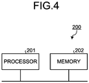
- the control unit 5 of the motor drive devices 100 and 100a can be implemented using a processing circuit 200 illustrated in FIG. 4 .
- the processing circuit 200 includes a general-purpose processor 201 and a memory 202, and the memory 202 stores a program for enabling the processor 201 to operate as the control unit 5. That is, the processor 201 reads from the memory 202 a program for enabling the processor 201 to operate as the control unit 5, and executes the program, and can thus implement the control unit 5.
- the memory 202 also holds information such as a threshold required for the processor 201 that operates as the control unit 5 to control the switches 91 to 93 of the switch unit 9.
- the processor 201 is a central processing unit (CPU) (also referred to as central processing unit, processing unit, computing unit, microprocessor, microcomputer, processor, and digital signal processor (DSP)), a system large scale integration (LSI), or the like.
- CPU central processing unit
- DSP digital signal processor
- LSI system large scale integration
- the memory 202 is a non-volatile or volatile semiconductor memory such as a random access memory (RAM), a read-only memory (ROM), a flash memory, an erasable programmable read-only memory (EPROM), an electrically erasable programmable read-only memory (EEPROM (registered trademark)); a magnetic disk, a flexible disk, an optical disk, a compact disc, a MiniDisc, a digital versatile disc (DVD), or the like.
- RAM random access memory
- ROM read-only memory
- EPROM erasable programmable read-only memory
- EEPROM electrically erasable programmable read-only memory
- control unit 5 may also be implemented in a dedicated hardware element such as a single circuit, a composite circuit, a programmed processor, a parallel programmed processor, an application specific integrated circuit (ASIC), a field programmable gate array (FPGA), or a circuit of combination thereof.
- ASIC application specific integrated circuit
- FPGA field programmable gate array
- the motor drive device is configured to include three relays for switching the connection configuration of the stator windings of the motor, three current detectors for detecting the internal states of the respective relays, and a control unit that, when detection results of the current detectors do not match, causes stopping of supplying power to the coils that respectively actuate the contact plates of the relays to match the internal states to the coils with one another.
- This enables the relays to have the same internal state to continue the operation of the motor even when electrical power cannot be supplied to the coil(s) of one or some of the relays, thereby enabling improved reliability of operation to be provided.
- FIG. 5 is a diagram illustrating an example configuration of a motor drive device according to a second embodiment.
- a motor drive device 100b according to the second embodiment is configured to include a state detection unit 7 in place of the state detection unit 6 of the motor drive device 100 illustrated in FIG. 1 , and also a control unit 5b instead of the control unit 5.
- the components other than the state detection unit 7 and the control unit 5b are similar to the components of the motor drive device 100 designated by like reference characters.
- the present embodiment will be described in terms of portions different from the motor drive device 100 according to the first embodiment.
- the state detection unit 7 includes current detectors 71 to 73, and detects the states of the contacts of the relays 11 to 13 respectively using these current detectors 71 to 73.
- the current detector 71 has one terminal coupled to the coil 31 of the relay 11 and the other terminal coupled to the switch 91.
- the current detector 71 detects a current flowing through the coil 31.
- the current detector 72 has one terminal coupled to the coil 32 of the relay 12 and the other terminal coupled to the switch 92.
- the current detector 72 detects a current flowing through the coil 32.
- the current detector 73 has one terminal coupled to the coil 33 of the relay 13 and the other terminal coupled to the switch 93.
- the current detector 73 detects a current flowing through the coil 33.
- the contact plate 21 of the relay 11 connects with the contact 51.
- the contact plate 22 of the relay 12 connects with the contact 52.
- the contact plate 23 of the relay 13 connects with the contact 53.
- the control unit 5b controls the switches 91 to 93 on the basis of respective detection results of the current detectors 71 to 73.
- the control unit 5b operates similarly to the control unit 5 described in the first embodiment except for providing control using detection results of the current detectors 71 to 73.
- the detection results of the current detectors 61 to 63 illustrated in FIG. 1 and the detection results of the current detectors 71 to 73 both change with changes in the internal states of the relays 11 to 13. This enables the control unit 5b to operate similarly to the control unit 5. Detailed description of the operation of the control unit 5b will be omitted.
- a configuration including current detectors that detect currents respectively flowing through the coils of the relays also enables the internal states of the relays to be detected, and thus allows the motor drive device 100b to provide control similar to the control of the motor drive devices 100 and 100a according to the first embodiment.
- a motor drive device can be provided that is capable of providing an advantage similar to the advantage of the first embodiment.
- FIG. 6 is a diagram illustrating another example configuration of the motor drive device according to the second embodiment.
- the current detector 74 detects a current flowing from the power supply 30 into the coils 31, 32, and 33 of the relays 11, 12, and 13.
- the control unit 5c controls the switches 91 to 93 on the basis of a detection result of the current detector 74. Specifically, in a case in which the current value at the current detector 74 is greater than zero and less than a threshold, the control unit 5c determines that the internal states of the relays 11 to 13 do not match, that is, the relays 11 to 13 are in states corresponding to the "No" case in the determination at step S14 of the flowchart illustrated in FIG. 2 .
- the threshold for use in this determination is set based on the current value when currents flow through all of the coils 31 to 33, to be less than this current value. For example, assuming that the current value detected by the current detector 74 when currents flow through all of the coils 31 to 33 is 3I, the threshold is set to satisfy a relationship of "2I ⁇ threshold ⁇ 3I".
- FIG. 7 is a diagram illustrating an example configuration of a motor drive device according to a third embodiment.
- a motor drive device 100d according to the third embodiment is configured to include a connection configuration switching unit 10d in place of the connection configuration switching unit 10 of the motor drive device 100b illustrated in FIG. 5 and a control unit 5d in place of the control unit 5b.
- the components other than the connection configuration switching unit 10d and the control unit 5d are similar to the components of the motor drive device 100b designated by like reference characters.
- the present embodiment will be described in terms of portions different from the motor drive device 100b according to the second embodiment.
- the connection configuration switching unit 10d includes relays 11d, 12d, and 13d. These relays 11d, 12d, and 13d are configured similarly to the relays 11, 12, and 13 described in the first embodiment, but the contacts thereof are coupled differently. Specifically, the contact 41 of the relay 11d is coupled to the corresponding output terminal of the inverter 2, and the contact 51 is coupled to the neutral point terminal 4. In addition, the contact 42 of the relay 12d is coupled to the corresponding output terminal of the inverter 2, and the contact 52 is coupled to the neutral point terminal 4; and the contact 43 of the relay 13d is coupled to the corresponding output terminal of the inverter 2, and the contact 53 is coupled to the neutral point terminal 4.
- the motor drive device 100d arranges the connection configuration of the stator windings of the motor 3 in the delta connection in an initial state in which no currents are flowing through the coils 31, 32, and 33 of the relays 11d, 12d, and 13d, and arranges the connection configuration of the stator windings of the motor 3 in the star connection when currents are flowing through the coils 31, 32, and 33.
- the control unit 5d controls the switches 91 to 93 on the basis of respective detection results of the current detectors 71 to 73.
- FIG. 8 is a flowchart illustrating an example of operation of switching the connection configuration of the stator windings of the motor 3 performed by the motor drive device 100d according to the third embodiment. The process at each step illustrated in FIG. 8 is performed by the control unit 5d.
- the operation according to the flowchart illustrated in FIG. 8 begins when the inverter 2 starts generation of AC voltage to be applied to the motor 3. It is assumed here that, at the time of the start of the operation, the switches 91 to 93 are in the open state and that the contact plates 21, 22, and 23 of the relays 11d, 12d, and 13d connect respectively with the contacts 41, 42, and 43. That is, it is assumed that the stator windings of the motor 3 are connected in delta connection.
- the motor drive device 100d starts supplying power to the relays 11d to 13d (step S21).
- the control unit 5d controls the switches 91 to 93 to set the switches 91 to 93 to the closed state to start supplying power respectively to the coils 31 to 33 of the relays 11d to 13d.
- This induces magnetic force in the coils 31 to 33 to move the contact plates 21 to 23 of the relays 11d to 13d.
- This connects the contact plate 21 to the contact 51, connects the contact plate 22 to the contact 52, and connects the contact plate 23 to the contact 53. That is, the connection configuration of the stator windings of the motor 3 is switched to the star connection.
- the motor drive device 100d checks the internal states of the respective relays 11d to 13d (step S22).
- the control unit 5d determines which of the two contacts the contact plates 21 to 23 of the relays 11d to 13d each connect with, on the basis of the current detection results of the current detectors 71 to 73 of the state detection unit 7. Specifically, the control unit 5d determines that the contact plate 21 of the relay 11d connects with the contact 51 if the current detector 71 detects a current, determines that the contact plate 22 of the relay 12d connects with the contact 52 if the current detector 72 detects a current, and determines that the contact plate 23 of the relay 13d connects with the contact 53 if the current detector 73 detects a current.
- the motor drive device 100d checks whether all the relays 11d to 13d have the same internal state (step S23).
- step S25 is a process of determining by the control unit 5d of whether the connection configuration needs to be switched to the delta connection.
- the threshold used is the same as the threshold used at step S11 illustrated in FIG. 2 .
- step S25: No If the operational frequency is less than or equal to the threshold (step S25: No), the motor drive device 100d returns to step S22 and continues the process. If the operational frequency is greater than the threshold (step S25: Yes), the motor drive device 100d stops supplying power to the relays 11d to 13d (step S26). Specifically, the control unit 5d controls the switches 91 to 93 to set the switches 91 to 93 to the open state to stop supplying power respectively to the coils 31 to 33 of the relays 11d to 13d. This stops the induction of magnetic force in the coils 31 to 33 to move the contact plates 21 to 23 of the relays 11d to 13d. This causes the contact plate 21 to connect with the contact 41, the contact plate 22 to connect with the contact 42, and the contact plate 23 to connect with the contact 43. That is, the connection configuration of the stator windings of the motor 3 is switched to the delta connection.
- step S27 is a reverse process of step S25 described above, that is, a process of determining by the control unit 5d of whether the connection configuration of the stator windings needs to be switched to the star connection.
- the threshold used is the same as the threshold used at step S16 illustrated in FIG. 2 .
- step S27: No If the operational frequency is greater than the threshold (step S27: No), the motor drive device 100d repeats the process at step S27.
- step S27: Yes If the operational frequency is less than or equal to the threshold (step S27: Yes), the motor drive device 100d returns to step S21 and continues the process.
- step S23 the motor drive device 100d stops supplying power to the relays 11d to 13d (step S24). This causes, similarly to when step S26 is performed, the connection configuration of the stator windings of the motor 3 to be switched to the delta connection.
- step S24 the motor drive device 100d terminates the operation of switching of the connection configuration of the stator windings, i.e., the operation according to the flowchart illustrated in FIG. 8 , and continues the operation, leaving the stator winding of the motor 3 connected in delta connection.
- step S23 results in "No" if the internal state of any one of the relays 11d to 13d fails to match the internal state of other relays due to a cause such as disconnection of the conductor wire of the coil.
- the connection configuration of the stator windings of the motor 3 is neither the star connection nor the delta connection, in which condition continuous operation of the motor 3 is undesirable. Accordingly, the motor drive device 100d performs step S24 to stop supplying power to the relays 11d to 13d to cause all the relays 11d to 13d to have the same internal state.
- the motor drive device 100d After performing step S24, the motor drive device 100d does not perform switching of the connection configuration of the stator windings of the motor 3 from the delta connection to the star connection even when the operational frequency exceeds the threshold, but can continue the operation of the motor 3. That is, even when the connection configuration switching unit 10d including the relays 11d to 13d for enabling switching of the connection configuration of the stator windings of the motor 3 fails, the motor drive device 100d can continue the operation of the motor 3.
- the motor drive device configured to continue, without stopping, the operation with the stator windings of the motor 3 being star-connected in a case in which one or some of the relays have an internal state different from the internal state of other relays, that is, when a condition in which current cannot flow to the coil(s) of one or some of the relays is detected.
- Operation in the star connection enables high efficiency operation in a low operational frequency range, but on the other hand, presents a problem of a significant reduction in the efficiency in a high operational frequency range, and presents another problem of high tendency to cause unstable operation and loss of synchronism under a high torque condition.
- the motor drive device 100d continues the operation with the stator windings of the motor 3 being delta-connected. Despite reduced efficiency in a low operational frequency range, this makes it less likely that unstable operation and loss of synchronism will occur under a high torque condition, thereby enabling stable operation even in a high speed range.
- the motor drive devices described in the first to third embodiments use a monostable relay as each of the relays 11, 12, 13, 11d, 12d, and 13d.
- a motor drive device according to the present embodiment uses a bistable relay for each of the relays 11, 12, 13, 11d, 12d, and 13d of the motor drive devices described in the first to third embodiments.
- the motor drive device according to the present embodiment is similar to the motor drive device described in each of the first to third embodiments except that the relays used are changed from monostable relays to bistable relays. Thus, operation only relating to the bistable relays will be described below.
- connection of the contact plates 21, 22, and 23 with the contacts 51, 52, and 53 requires currents to continuously flow through the coils 31, 32, and 33. That is, when currents are flowing through the coils 31, 32, and 33, the contact plates 21, 22, and 23 are connected with the contacts 51, 52, and 53, while when no currents are flowing through the coils 31, 32, and 33, the contact plates 21, 22, and 23 are connected with the contacts 41, 42, and 43.
- the motor drive devices 100, 100a, 100b, and 100c described in the first and second embodiments are required to allow currents to continuously flow through the coils 31, 32, and 33 during operation performed when the stator windings of the motor 3 are delta-connected, and thus each have an issue with increase in power consumption in the coils 31, 32, and 33.
- the motor drive device 100d described in the third embodiment is required to allow currents to continuously flow through the coils 31, 32, and 33 during operation performed when the stator windings of the motor 3 are star-connected, and thus has an issue with increase in power consumption in the coils 31, 32, and 33.
- the motor drive device uses, as described above, bistable relays in place of monostable relays.
- a bistable relay requires current to flow only for a certain predetermined time period to switch the contact with which a contact plate is connected, and does not require continuous current flow to maintain the connection state.
- the contact plate 21 can be switched from being connected to the contact 41 to being connected the contact 51 by closing the switch 91 only for a certain time period to pass a current through the coil 31, and even if the switch 91 is opened to stop current flow through the coil 31 after the certain time period has elapsed, it is still possible to keep the contact plate 21 connecting with the contact 51.
- the contact plate 21 can be switched from being connected with the contact 51 to being connected with the contact 41 by closing the switch 91 only for the certain time period to pass a current through the coil 31.
- FIG. 9 is a flowchart illustrating an example of operation of switching the connection configuration of the stator windings of the motor 3 performed by the motor drive device 100 according to a fourth embodiment.
- the flowchart illustrated in FIG. 9 includes steps S32, S35, and S37 in place of steps S12, S15, and S17, respectively, in the flowchart illustrated in FIG. 2 , and additionally includes steps S38 and S39.
- the motor drive device 100 supplies electrical power to the relays 11 to 13 for a certain time period.
- step S38 the motor drive device 100 checks the internal states of the respective relays (step S38), and then checks whether all the relays 11 to 13 have the same internal state (step S39).
- steps S38 and S39 are similar processes to steps S13 and S14. If all the relays 11 to 13 have the same internal state (step S39: Yes), the motor drive device 100 returns to step S11 and continues the process. If not all the relays 11 to 13 have the same internal state, that is, if one or some relays of the relays 11 to 13 have an internal state different from the internal state of the other relay(s) (step S39: No), the motor drive device 100 performs step S35.
- Step S35 is performed when one or some relays of the relays 11 to 13 have an internal state different from the internal state of the other relay(s), in which condition the contact with which the contact plate is connected is not switched for the relay whose coil cannot be supplied with a current due to a cause such as disconnection. On the contrary, the contact with which the contact plate is connected is switched for each of the other relay(s) whose coil can be supplied with a current. Therefore, after the performance of step S35, the relays 11 to 13 will have the same internal state, and the stator windings of the motor 3 will be connected in star connection or in delta connection. Thus, even when one or some of the relays 11 to 13 fail and can no longer switch the state(s) of the corresponding contact plate(s), the motor drive device 100 can continue the operation of the motor 3.
- the process can be performed such that, for example, steps S21, S24, and S26 of the flowchart illustrated in FIG. 8 are each replaced by the process of supplying electrical power to the relays 11d to 13d for a certain time period.
- the motor drive device 100d after performing the process performed instead of step S26, i.e., "process of supplying electrical power to the relays 11d to 13d for a certain time period", the motor drive device 100d checks whether all the relays 11d to 13d have the same internal state. If all the relays 11d to 13d have the same internal state, the motor drive device 100d performs step S27.
- the motor drive device 100d supplies electrical power to the relays 11d to 13d for a certain time period, and then terminates the operation of switching of the connection configuration of the stator windings of the motor 3. That is, the motor drive device 100d supplies electrical power to the relays 11d to 13d for a certain time period to actuate the contact plates 21 to 23, then checks the internal states of the respective relays, and if not all the internal states are the same, performs a process of setting the relays to the same internal state. Then, the motor drive device 100d terminates the operation of switching of the connection configuration of the stator windings of the motor 3.
Landscapes
- Engineering & Computer Science (AREA)
- Power Engineering (AREA)
- Control Of Ac Motors In General (AREA)
- Control Of Multiple Motors (AREA)
Abstract
Description
- The present invention relates to a motor drive device that drives a motor configured such that the connection configuration of the stator windings can be switched.
- As an example of conventional motor drive devices, there is a motor drive device that selects a star connection during start-up of the motor and when the operational frequency is less than or equal to a predetermined value, and selects a delta connection when the operational frequency is greater than the predetermined value, and thus provides improved efficiency (Patent Literature 1).
-
Patent Literature 1 discloses, as one form of motor drive device, a configuration to use three change-over-contact relays and to switch the state of the contact of each of the change-over-contact relays, thus to switch the connection configuration of the stator windings. - Patent Literature 1: Japanese Patent Application Laid-open No.
2008-228513 - The foregoing conventional configuration uses a coil to switch the contact plate of a relay, and passes a current through the coil to move the contact plate, which is a movable part. Thus, failure to supply electrical power to the coil(s) of one or some of the relays, more specifically, for example, occurrence of disconnection of the conductor wire of a coil, prevents the contact plate from being moved. This causes the contact plate of that relay to be held in contact with only one of the contacts. That is, even when a need arises to switch the connection configuration in response to a change in the operational frequency and the contact plate of each of the relays is then actuated, the state of the contact plate of each of the one or some of the relays will not change. This causes the connection configuration to be neither the star connection nor the delta connection, thereby presenting a problem in that normal operation cannot be performed. Alternatively, failure of the contact plate itself may prevent the contact plate from being moved and may thus prevent normal switching of the connection configuration even in a state where a current can pass through the coil.
- The present invention has been made in view of the foregoing, and it is an object of the present invention to provide a motor drive device capable of providing improved reliability of motor operation.
- To solve the problem and achieve the object described above, an aspect of the present invention is directed to a motor drive device capable of switching a connection configuration of stator windings of a motor.
The motor drive device includes three relays each including a first contact, a second contact, and a contact plate, wherein the contact plate has one terminal coupled to a stator winding of one phase among the stator windings and the contact plate has another terminal to be connected to the first contact or to the second contact. The motor drive device further includes a control unit to control the three relays to cause all the three relays to have a same connection state in a case in which not all the three relays have a same connection state with respect to a connection between the another terminal of the contact plate and the first contact and the second contact. - A motor drive device according to the present invention provides an advantage of being capable of providing improved reliability of motor operation.
-
-
FIG. 1 is a diagram illustrating an example configuration of a motor drive device according to a first embodiment. -
FIG. 2 is a flowchart illustrating an example of operation of switching the connection configuration of the stator windings of the motor performed by the motor drive device according to the first embodiment. -
FIG. 3 is a diagram illustrating another example configuration of the motor drive device according to the first embodiment. -
FIG. 4 is a diagram illustrating an example of hardware element to implement the control unit of the motor drive device according to the first embodiment. -
FIG. 5 is a diagram illustrating an example configuration of a motor drive device according to a second embodiment. -
FIG. 6 is a diagram illustrating another example configuration of the motor drive device according to the second embodiment. -
FIG. 7 is a diagram illustrating an example configuration of a motor drive device according to a third embodiment. -
FIG. 8 is a flowchart illustrating an example of operation of switching the connection configuration of the stator windings of the motor performed by the motor drive device according to the third embodiment. -
FIG. 9 is a flowchart illustrating an example of operation of switching the connection configuration of the stator windings of the motor performed by a motor drive device according to a fourth embodiment. - A motor drive device according to embodiments of the present invention will be described in detail below with reference to the drawings. Note that these embodiments are not intended to limit the scope of this invention.
-
FIG. 1 is a diagram illustrating an example configuration of a motor drive device according to a first embodiment of the present invention. Amotor drive device 100 according to the first embodiment includes acapacitor 1, aninverter 2, acontrol unit 5, astate detection unit 6, aswitch unit 9, a connectionconfiguration switching unit 10, and apower supply 30. - The
capacitor 1 holds direct current (DC) power supplied from a converter (not illustrated) or the like in the form of DC voltage. Theinverter 2 converts the DC voltage held by thecapacitor 1 into alternating current (AC) voltage by means of pulse width modulation, and applies the AC voltage to a motor 3 to be driven. It is assumed here that the motor 3 has three stator windings having both ends open and is configured such that the connection configuration thereof can be changed. Note thatFIG. 1 omits the control circuit for controlling the switching devices included in theinverter 2. The control circuit for controlling the switching devices of theinverter 2 can be implemented using a publicly known circuit. - The
control unit 5 actuates contact plates respectively included inrelays 11 to 13 described later by controlling theswitch unit 9 to change the connection configuration of the stator windings of the motor 3. Thestate detection unit 6 includescurrent detectors 61 to 63, and detects the states of the contact plates of therelays 11 to 13 respectively using thesecurrent detectors 61 to 63. Theswitch unit 9 includesswitches 91 to 93, and opens and closes theswitches 91 to 93 on the basis of control by thecontrol unit 5. Theswitches 91 to 93 are opened and closed synchronously with one another. That is, theswitches 91 to 93 transition from an open state to a closed state at same time, and transition from a closed state to an open state at same time. - The connection
configuration switching unit 10 includes therelays 11 to 13, and switches the connection configuration of the stator windings of the motor 3 between a star connection and a delta connection. Therelays 11 to 13 are each a change-over-contact relay, and each include a contact plate having one terminal coupled to a stator winding and the other terminal to be connected to a first contact or to a second contact; and a coil for actuating the contact plate. As illustrated, therelay 11 includes acontact plate 21,contacts coil 31. Thecontact plate 21 connects to thecontact 41, which is the first contact, in an initial state in which no current is flowing through thecoil 31, and connects to thecontact 51, which is the second contact, when a current is flowing through thecoil 31. Similarly, therelay 12 includes acontact plate 22,contacts coil 32. Thecontact plate 22 connects to thecontact 42, which is the first contact, in the initial state in which no current is flowing through thecoil 32, and connects to thecontact 52, which is the second contact, when a current is flowing through thecoil 32. Therelay 13 includes acontact plate 23,contacts coil 33. Thecontact plate 23 connects to thecontact 43, which is the first contact, in the initial state in which no current is flowing through thecoil 33, and connects to thecontact 53, which is the second contact, when a current is flowing through thecoil 33. - The
power supply 30 generates a current that flows through thecoils 31 to 33 respectively included in therelays 11 to 13. Note that theswitch 91 of theswitch unit 9 described above in a closed state causes a current to flow through thecoil 31 of therelay 11; theswitch 92 in a closed state causes a current to flow through thecoil 32 of therelay 12; and theswitch 93 in a closed state causes a current to flow through thecoil 33 of therelay 13. Thepower supply 30 may be, for example, a power conversion circuit that converts the DC voltage held by thecapacitor 1 into a desired voltage and applies that voltage across thecoils 31 to 33. - The three stator windings of the motor 3 each have one terminal coupled to a corresponding one of three output terminals of the
inverter 2 and the other terminal coupled to a corresponding one of thecontact plates relays contacts neutral point terminal 4 respectively via thecurrent detectors contacts inverter 2. - The
current detector 61 of thestate detection unit 6 has one terminal coupled to thecontact 41 of therelay 11 and the other terminal coupled to theneutral point terminal 4. Theneutral point terminal 4 is on the neutral point when the stator windings of the motor 3 are connected in star connection. In addition, thecurrent detector 62 has one terminal coupled to thecontact 42 of therelay 12 and the other terminal coupled to theneutral point terminal 4. Thecurrent detector 63 has one terminal coupled to thecontact 43 of therelay 13 and the other terminal coupled to theneutral point terminal 4. As described above, thecontact plates relays inverter 2 operates to allow a current to flow into the stator windings of the motor 3, when thecontact plate 21 of therelay 11 is connected with thecontact 41, thecurrent detector 61 detects the current; however, when thecontact plate 21 is not connected with thecontact 41, thecurrent detector 61 detects no current. In addition, when thecontact plate 22 of therelay 12 is connected with thecontact 42, thecurrent detector 62 detects the current; however, when thecontact plate 22 is not connected with thecontact 42, thecurrent detector 62 detects no current. When thecontact plate 23 of therelay 13 is connected with thecontact 43, thecurrent detector 63 detects the current; however, when thecontact plate 23 is not connected with thecontact 43, thecurrent detector 63 detects no current. - Accordingly, a detection result of the
current detector 61 indicates the state of thecontact plate 21 of therelay 11, i.e., whether thecontact plate 21 is connected with thecontact 41. The state of thecontact plate 21 not connected with thecontact 41 includes a state in which thecontact plate 21 is connected with thecontact 51 and a state in which thecontact plate 21 connects with neither of thecontact 41 and thecontact 51. The state in which thecontact plate 21 connects with neither of thecontact 41 and thecontact 51 includes, for example, a state in which an electrically insulating foreign matter is jammed between thecontact plate 21 and thecontact 41 when no current is flowing through thecoil 31, thereby preventing thecontact plate 21 from coming into contact with thecontact 41; a state in which an electrically insulating foreign matter is jammed between thecontact plate 21 and thecontact 51 when a current is flowing through thecoil 31, thereby preventing thecontact plate 21 from coming into contact with thecontact 51; and the like. Similarly, a detection result of thecurrent detector 62 indicates the state of thecontact plate 22 of therelay 12, and a detection result of thecurrent detector 63 indicates the state of thecontact plate 23 of therelay 13. Note that when thecontact plate 21 connects with thecontact 41, thecontact plate 22 connects with thecontact 42, and thecontact plate 23 connects with thecontact 43, the stator windings of the motor 3 are being connected in star connection. In contrast, when thecontact plate 21 connects with thecontact 51, thecontact plate 22 connects with thecontact 52, and thecontact plate 23 connects with thecontact 53, the stator windings of the motor 3 are being connected in delta connection. Note that the following description refers to the connection state with respect to connections between the contact plate and the first contact and the second contact in each of the relays as "internal state". - An operation of the
motor drive device 100 of switching the connection configuration of the stator windings of the motor 3 will next be described.FIG. 2 is a flowchart illustrating an example of operation of switching the connection configuration of the stator windings of the motor 3 performed by themotor drive device 100. The process at each step illustrated inFIG. 2 is performed by thecontrol unit 5. - The operation according to the flowchart illustrated in
FIG. 2 begins when theinverter 2 starts generation of AC voltage to be applied to the motor 3. It is assumed here that, at the time of the start of the operation, theswitches 91 to 93 are in the open state, and that thecontact plates relays contacts - Upon starting of application of AC voltage to the motor 3, the
motor drive device 100 checks whether the operational frequency of the motor 3 is greater than a predetermined threshold (step S11). A motor whose connection configuration of the stator windings is switchable between a star connection and a delta connection can operate more efficiently in a star connection at a low operational frequency, and can operate more efficiently in a delta connection at an operational frequency greater than a certain value. Accordingly, a motor whose connection configuration of the stator windings is switchable between a star connection and a delta connection can operate efficiently by selecting the star connection at the start of the operation and selecting the delta connection when the operational frequency is greater than a certain value. Step S11 is a process of determining by thecontrol unit 5 of whether the connection configuration needs to be switched to the delta connection. The operational frequency can be calculated based on, for example, the rotational speed detected by a rotational speed detector (not illustrated) attached to the motor 3. The threshold for use in the comparison with the operational frequency can be set to the operational frequency at which the operating efficiency when the stator windings of the motor 3 are connected in star connection exceeds or falls below the operating efficiency when the stator windings of the motor 3 are connected in delta connection. - If the operational frequency is less than or equal to the threshold (step S11: No), the
motor drive device 100 repeats the process at step S11. If the operational frequency is greater than the threshold (step S11: Yes), themotor drive device 100 starts supplying power to therelays 11 to 13 (step S12). Specifically, thecontrol unit 5 controls theswitches 91 to 93 to set theswitches 91 to 93 to the closed state to start supplying power respectively to thecoils 31 to 33 of therelays 11 to 13. This induces magnetic force in thecoils 31 to 33 to move thecontact plates 21 to 23 of therelays 11 to 13. This connects thecontact plate 21 to thecontact 51, connects thecontact plate 22 to thecontact 52, and connects thecontact plate 23 to thecontact 53. That is, the connection configuration of the stator windings of the motor 3 is switched to the delta connection. - Next, the
motor drive device 100 checks the internal states of therelays 11 to 13 (step S13). At this step S13, thecontrol unit 5 determines which of the two contacts thecontact plates 21 to 23 of therelays 11 to 13 each connect with, on the basis of the current detection results of thecurrent detectors 61 to 63 of thestate detection unit 6. Specifically, thecontrol unit 5 determines that thecontact plate 21 of therelay 11 connects with thecontact 41 if thecurrent detector 61 detects a current, determines that thecontact plate 22 of therelay 12 connects with thecontact 42 if thecurrent detector 62 detects a current, and determines that thecontact plate 23 of therelay 13 connects with thecontact 43 if thecurrent detector 63 detects a current. Note that if thecurrent detector 61 detects no current, thecontrol unit 5 determines that thecontact plate 21 of therelay 11 connects with thecontact 51 or that thecontact plate 21 connects with neither of thecontact 41 and thecontact 51. A similar operation is performed if thecurrent detectors - Then, the
motor drive device 100 checks whether all therelays 11 to 13 have the same internal state (step S14) . - If all the
relays 11 to 13 have the same internal state (step S14: Yes), themotor drive device 100 checks whether the operational frequency of the motor 3 is less than or equal to a predetermined threshold (step S16).
This step S16 is a reverse process of step S11 described above, that is, a process of determining by thecontrol unit 5 of whether the connection configuration of the stator windings needs to be switched to the star connection. Note that the threshold used at step S16 may be the same as or may be different from the threshold used at step S11.
In the case of using a threshold different from the threshold used at step S11, the threshold used at step S16 is set to a value lower than the threshold used at step S11. - If the operational frequency is greater than the threshold (step S16: No), the
motor drive device 100 returns to step S13 and continues the process. - If the operational frequency is less than or equal to the threshold (step S16: Yes), the
motor drive device 100 stops supplying power to therelays 11 to 13 (step S17). Specifically, thecontrol unit 5 controls theswitches 91 to 93 to set theswitches 91 to 93 to the open state to stop supplying power respectively to thecoils 31 to 33 of therelays 11 to 13. This stops the induction of magnetic force in thecoils 31 to 33 to move thecontact plates 21 to 23 of therelays 11 to 13. This causes thecontact plate 21 to connect with thecontact 41, thecontact plate 22 to connect with thecontact 42, and thecontact plate 23 to connect with thecontact 43. That is, the connection configuration of the stator windings of the motor 3 is switched to the star connection. After performing step S17, themotor drive device 100 returns to step S11 and continues the process. - Otherwise, if not all the
relays 11 to 13 have the same internal state, that is, if one or some relays of therelays 11 to 13 have an internal state different from the internal state of the other relay(s) (step S14: No), themotor drive device 100 stops supplying power to therelays 11 to 13 (step S15). This causes, similarly to when step S17 is performed, the connection configuration of the stator windings of the motor 3 to be switched to the star connection. After performing step S15, themotor drive device 100 terminates the operation of switching of the connection configuration of the stator windings, i.e., the operation according to the flowchart illustrated inFIG. 2 , and continues the operation, leaving the stator windings of the motor 3 connected in star connection. The determination at step S14 results in "No" if the internal state of any one of therelays 11 to 13 fails to match the internal state of other relays due to a cause such as disconnection of the conductor wire of the coil. In this case, the connection configuration of the stator windings of the motor 3 is neither the star connection nor the delta connection, in which condition continuous operation of the motor 3 is undesirable. Accordingly, themotor drive device 100 performs step S15 to stop supplying power to therelays 11 to 13 to cause all therelays 11 to 13 to have the same internal state. After performing step S15, themotor drive device 100 does not perform switching of the connection configuration of the stator windings of the motor 3 from the star connection to the delta connection even when the operational frequency exceeds the threshold, but can continue the operation of the motor 3. That is, even when the connectionconfiguration switching unit 10 including therelays 11 to 13 for enabling switching of the connection configuration of the stator windings of the motor 3 fails, themotor drive device 100 can continue the operation of the motor 3. - Note that the process may be performed such that processes similar to steps S13 and S14 are performed again after performing step S15 to check whether the
relays 11 to 13 have the same internal state and that themotor drive device 100 continues the operation of the motor 3 if therelays 11 to 13 have the same internal state and otherwise stops the operation of the motor 3. In this case, the user may be informed of the occurrence of failure using a notification unit not illustrated. - In addition, the foregoing description assumes that the process returns to step S11 after the performance of step 17, but the
motor drive device 100 may perform a process similar to step S13 after performing step S17 to check the internal states of the respective relays. In this case, if all therelays 11 to 13 have the same internal state, themotor drive device 100 returns to step S11 and continues the process. Alternatively, if one or some relays of therelays 11 to 13 have an internal state different from the internal state of the other relay(s), themotor drive device 100 restarts supplying power to therelays 11 to 13 to change the connection configuration of the stator windings of the motor 3 back to the delta connection. After this, similarly to the case of performing step S15 as described above, themotor drive device 100 terminates the operation of switching of the connection configuration of the stator windings. Thus, even when one of thecontact plates 21 to 23 of therelays 11 to 13 fails and becomes stuck to the side of the corresponding output terminal of theinverter 2, this situation can be detected, and thecontrol unit 5 then provides control to cause thecontact plates 21 to 23 of therelays 11 to 13 to have the same state, and can thus continue the operation while maintaining the connection configuration of the stator windings of the motor 3 in the delta connection. - Although the
motor drive device 100 includes thecurrent detectors 61 to 63 between theneutral point terminal 4 and therelays 11 to 13, the current detectors may be disposed between the output terminals of theinverter 2 and therelays 11 to 13. An example configuration of the motor drive device in such case is illustrated inFIG. 3. FIG. 3 is a diagram illustrating another example configuration of the motor drive device according to the first embodiment. Amotor drive device 100a illustrated inFIG. 3 includes astate detection unit 6a in place of thestate detection unit 6 of themotor drive device 100. - The
state detection unit 6a includescurrent detectors 64 to 66 having functionality similar to the functionality of thecurrent detectors 61 to 63 described above. Thecurrent detector 64 is disposed between the corresponding output terminal of theinverter 2 and thecontact 51 of therelay 11. In addition, thecurrent detector 65 is disposed between the corresponding output terminal of theinverter 2 and thecontact 52 of therelay 12; and thecurrent detector 66 is disposed between the corresponding output terminal of theinverter 2 and thecontact 53 of therelay 13. Thecurrent detector 64 detects a current when thecontact plate 21 of therelay 11 connects with thecontact 51. Thecurrent detector 65 detects a current when thecontact plate 22 of therelay 12 connects with thecontact 52. Thecurrent detector 66 detects a current when thecontact plate 23 of therelay 13 connects with thecontact 53. - The
motor drive device 100a can also switch the connection configuration of the stator windings of the motor 3 between a star connection and a delta connection using a procedure similar to the procedure used by themotor drive device 100, and can also continue the operation of the motor 3 even when the connectionconfiguration switching unit 10 including therelays 11 to 13 fails. - Moreover, the
current detectors 61 to 63 illustrated inFIG. 1 may also be included in the configuration in addition to thecurrent detectors 64 to 66. This configuration enables correct detection of the connection state of both the star connection and the delta connection, and thus enables thecontrol unit 5 to more correctly perform switching of the connection configuration of the stator windings to provide continuous operation of the motor 3. - A hardware element to implement the
control unit 5 of themotor drive devices control unit 5 of themotor drive devices processing circuit 200 illustrated inFIG. 4 . - The
processing circuit 200 includes a general-purpose processor 201 and amemory 202, and thememory 202 stores a program for enabling theprocessor 201 to operate as thecontrol unit 5. That is, theprocessor 201 reads from the memory 202 a program for enabling theprocessor 201 to operate as thecontrol unit 5, and executes the program, and can thus implement thecontrol unit 5. Thememory 202 also holds information such as a threshold required for theprocessor 201 that operates as thecontrol unit 5 to control theswitches 91 to 93 of theswitch unit 9. Theprocessor 201 is a central processing unit (CPU) (also referred to as central processing unit, processing unit, computing unit, microprocessor, microcomputer, processor, and digital signal processor (DSP)), a system large scale integration (LSI), or the like. Thememory 202 is a non-volatile or volatile semiconductor memory such as a random access memory (RAM), a read-only memory (ROM), a flash memory, an erasable programmable read-only memory (EPROM), an electrically erasable programmable read-only memory (EEPROM (registered trademark)); a magnetic disk, a flexible disk, an optical disk, a compact disc, a MiniDisc, a digital versatile disc (DVD), or the like. - Note that the
control unit 5 may also be implemented in a dedicated hardware element such as a single circuit, a composite circuit, a programmed processor, a parallel programmed processor, an application specific integrated circuit (ASIC), a field programmable gate array (FPGA), or a circuit of combination thereof. - As described above, the motor drive device according to the present embodiment is configured to include three relays for switching the connection configuration of the stator windings of the motor, three current detectors for detecting the internal states of the respective relays, and a control unit that, when detection results of the current detectors do not match, causes stopping of supplying power to the coils that respectively actuate the contact plates of the relays to match the internal states to the coils with one another. This enables the relays to have the same internal state to continue the operation of the motor even when electrical power cannot be supplied to the coil(s) of one or some of the relays, thereby enabling improved reliability of operation to be provided.
-
FIG. 5 is a diagram illustrating an example configuration of a motor drive device according to a second embodiment. Amotor drive device 100b according to the second embodiment is configured to include a state detection unit 7 in place of thestate detection unit 6 of themotor drive device 100 illustrated inFIG. 1 , and also acontrol unit 5b instead of thecontrol unit 5. The components other than the state detection unit 7 and thecontrol unit 5b are similar to the components of themotor drive device 100 designated by like reference characters. The present embodiment will be described in terms of portions different from themotor drive device 100 according to the first embodiment. - The state detection unit 7 includes
current detectors 71 to 73, and detects the states of the contacts of therelays 11 to 13 respectively using thesecurrent detectors 71 to 73. Thecurrent detector 71 has one terminal coupled to thecoil 31 of therelay 11 and the other terminal coupled to theswitch 91. Thecurrent detector 71 detects a current flowing through thecoil 31. Thecurrent detector 72 has one terminal coupled to thecoil 32 of therelay 12 and the other terminal coupled to theswitch 92. Thecurrent detector 72 detects a current flowing through thecoil 32. Thecurrent detector 73 has one terminal coupled to thecoil 33 of therelay 13 and the other terminal coupled to theswitch 93. Thecurrent detector 73 detects a current flowing through thecoil 33. - When the
current detector 71 detects a current, that is, when a current is flowing through thecoil 31, thecontact plate 21 of therelay 11 connects with thecontact 51. Similarly, when thecurrent detector 72 detects a current, thecontact plate 22 of therelay 12 connects with thecontact 52. When thecurrent detector 73 detects a current, that is, when a current is flowing through thecoil 33, thecontact plate 23 of therelay 13 connects with thecontact 53. - The
control unit 5b controls theswitches 91 to 93 on the basis of respective detection results of thecurrent detectors 71 to 73. Thecontrol unit 5b operates similarly to thecontrol unit 5 described in the first embodiment except for providing control using detection results of thecurrent detectors 71 to 73. The detection results of thecurrent detectors 61 to 63 illustrated inFIG. 1 and the detection results of thecurrent detectors 71 to 73 both change with changes in the internal states of therelays 11 to 13. This enables thecontrol unit 5b to operate similarly to thecontrol unit 5. Detailed description of the operation of thecontrol unit 5b will be omitted. - As described above, a configuration including current detectors that detect currents respectively flowing through the coils of the relays also enables the internal states of the relays to be detected, and thus allows the
motor drive device 100b to provide control similar to the control of themotor drive devices - Note that a
motor drive device 100c configured as illustrated inFIG. 6 , that is, configured to include acurrent detector 74 in place of thecurrent detectors 71 to 73 of themotor drive device 100b and acontrol unit 5c in place of thecontrol unit 5b can also provide a similar operation, and thus also provides a similar advantage.FIG. 6 is a diagram illustrating another example configuration of the motor drive device according to the second embodiment. - In the
motor drive device 100c illustrated inFIG. 6 , thecurrent detector 74 detects a current flowing from thepower supply 30 into thecoils relays - The
control unit 5c controls theswitches 91 to 93 on the basis of a detection result of thecurrent detector 74. Specifically, in a case in which the current value at thecurrent detector 74 is greater than zero and less than a threshold, thecontrol unit 5c determines that the internal states of therelays 11 to 13 do not match, that is, therelays 11 to 13 are in states corresponding to the "No" case in the determination at step S14 of the flowchart illustrated inFIG. 2 . The threshold for use in this determination is set based on the current value when currents flow through all of thecoils 31 to 33, to be less than this current value. For example, assuming that the current value detected by thecurrent detector 74 when currents flow through all of thecoils 31 to 33 is 3I, the threshold is set to satisfy a relationship of "2I<threshold<3I". -
FIG. 7 is a diagram illustrating an example configuration of a motor drive device according to a third embodiment. Amotor drive device 100d according to the third embodiment is configured to include a connectionconfiguration switching unit 10d in place of the connectionconfiguration switching unit 10 of themotor drive device 100b illustrated inFIG. 5 and acontrol unit 5d in place of thecontrol unit 5b. The components other than the connectionconfiguration switching unit 10d and thecontrol unit 5d are similar to the components of themotor drive device 100b designated by like reference characters. The present embodiment will be described in terms of portions different from themotor drive device 100b according to the second embodiment. - The connection
configuration switching unit 10d includesrelays relays relays contact 41 of therelay 11d is coupled to the corresponding output terminal of theinverter 2, and thecontact 51 is coupled to theneutral point terminal 4. In addition, thecontact 42 of therelay 12d is coupled to the corresponding output terminal of theinverter 2, and thecontact 52 is coupled to theneutral point terminal 4; and thecontact 43 of therelay 13d is coupled to the corresponding output terminal of theinverter 2, and thecontact 53 is coupled to theneutral point terminal 4. - The
motor drive device 100d arranges the connection configuration of the stator windings of the motor 3 in the delta connection in an initial state in which no currents are flowing through thecoils relays coils - The
control unit 5d controls theswitches 91 to 93 on the basis of respective detection results of thecurrent detectors 71 to 73. - An operation of the
motor drive device 100d of switching the connection configuration of the stator windings of the motor 3 will next be described.FIG. 8 is a flowchart illustrating an example of operation of switching the connection configuration of the stator windings of the motor 3 performed by themotor drive device 100d according to the third embodiment. The process at each step illustrated inFIG. 8 is performed by thecontrol unit 5d. - The operation according to the flowchart illustrated in
FIG. 8 begins when theinverter 2 starts generation of AC voltage to be applied to the motor 3. It is assumed here that, at the time of the start of the operation, theswitches 91 to 93 are in the open state and that thecontact plates relays contacts - Upon starting of application of AC voltage to the motor 3, the
motor drive device 100d starts supplying power to therelays 11d to 13d (step S21). Specifically, thecontrol unit 5d controls theswitches 91 to 93 to set theswitches 91 to 93 to the closed state to start supplying power respectively to thecoils 31 to 33 of therelays 11d to 13d. This induces magnetic force in thecoils 31 to 33 to move thecontact plates 21 to 23 of therelays 11d to 13d. This connects thecontact plate 21 to thecontact 51, connects thecontact plate 22 to thecontact 52, and connects thecontact plate 23 to thecontact 53. That is, the connection configuration of the stator windings of the motor 3 is switched to the star connection. - Next, the
motor drive device 100d checks the internal states of therespective relays 11d to 13d (step S22). At this step S22, thecontrol unit 5d determines which of the two contacts thecontact plates 21 to 23 of therelays 11d to 13d each connect with, on the basis of the current detection results of thecurrent detectors 71 to 73 of the state detection unit 7. Specifically, thecontrol unit 5d determines that thecontact plate 21 of therelay 11d connects with thecontact 51 if thecurrent detector 71 detects a current, determines that thecontact plate 22 of therelay 12d connects with thecontact 52 if thecurrent detector 72 detects a current, and determines that thecontact plate 23 of therelay 13d connects with thecontact 53 if thecurrent detector 73 detects a current. - Then, the
motor drive device 100d checks whether all therelays 11d to 13d have the same internal state (step S23). - If all the
relays 11d to 13d have the same internal state (step S23: Yes), themotor drive device 100d checks whether the operational frequency of the motor 3 is greater than a predetermined threshold (step S25). This step S25 is a process of determining by thecontrol unit 5d of whether the connection configuration needs to be switched to the delta connection. The threshold used is the same as the threshold used at step S11 illustrated inFIG. 2 . - If the operational frequency is less than or equal to the threshold (step S25: No), the
motor drive device 100d returns to step S22 and continues the process. If the operational frequency is greater than the threshold (step S25: Yes), themotor drive device 100d stops supplying power to therelays 11d to 13d (step S26). Specifically, thecontrol unit 5d controls theswitches 91 to 93 to set theswitches 91 to 93 to the open state to stop supplying power respectively to thecoils 31 to 33 of therelays 11d to 13d. This stops the induction of magnetic force in thecoils 31 to 33 to move thecontact plates 21 to 23 of therelays 11d to 13d. This causes thecontact plate 21 to connect with thecontact 41, thecontact plate 22 to connect with thecontact 42, and thecontact plate 23 to connect with thecontact 43. That is, the connection configuration of the stator windings of the motor 3 is switched to the delta connection. - Next, the
motor drive device 100d checks whether the operational frequency of the motor 3 is less than or equal to a predetermined threshold (step S27). This step S27 is a reverse process of step S25 described above, that is, a process of determining by thecontrol unit 5d of whether the connection configuration of the stator windings needs to be switched to the star connection. The threshold used is the same as the threshold used at step S16 illustrated inFIG. 2 . - If the operational frequency is greater than the threshold (step S27: No), the
motor drive device 100d repeats the process at step S27. - If the operational frequency is less than or equal to the threshold (step S27: Yes), the
motor drive device 100d returns to step S21 and continues the process. - Otherwise, if not all the
relays 11d to 13d have the same internal state, that is, if one or some relays of therelays 11d to 13d have an internal state different from the internal state of the other relay(s) (step S23: No), themotor drive device 100d stops supplying power to therelays 11d to 13d (step S24). This causes, similarly to when step S26 is performed, the connection configuration of the stator windings of the motor 3 to be switched to the delta connection. After performing step S24, themotor drive device 100d terminates the operation of switching of the connection configuration of the stator windings, i.e., the operation according to the flowchart illustrated inFIG. 8 , and continues the operation, leaving the stator winding of the motor 3 connected in delta connection. The determination at step S23 results in "No" if the internal state of any one of therelays 11d to 13d fails to match the internal state of other relays due to a cause such as disconnection of the conductor wire of the coil. In this case, the connection configuration of the stator windings of the motor 3 is neither the star connection nor the delta connection, in which condition continuous operation of the motor 3 is undesirable. Accordingly, themotor drive device 100d performs step S24 to stop supplying power to therelays 11d to 13d to cause all therelays 11d to 13d to have the same internal state. After performing step S24, themotor drive device 100d does not perform switching of the connection configuration of the stator windings of the motor 3 from the delta connection to the star connection even when the operational frequency exceeds the threshold, but can continue the operation of the motor 3. That is, even when the connectionconfiguration switching unit 10d including therelays 11d to 13d for enabling switching of the connection configuration of the stator windings of the motor 3 fails, themotor drive device 100d can continue the operation of the motor 3. - The motor drive device according to each of the first and second embodiments described above is configured to continue, without stopping, the operation with the stator windings of the motor 3 being star-connected in a case in which one or some of the relays have an internal state different from the internal state of other relays, that is, when a condition in which current cannot flow to the coil(s) of one or some of the relays is detected. Operation in the star connection enables high efficiency operation in a low operational frequency range, but on the other hand, presents a problem of a significant reduction in the efficiency in a high operational frequency range, and presents another problem of high tendency to cause unstable operation and loss of synchronism under a high torque condition. In contrast, upon determination that one or some of the relays have an internal state different from the internal state of other relays, the
motor drive device 100d according to the present embodiment continues the operation with the stator windings of the motor 3 being delta-connected. Despite reduced efficiency in a low operational frequency range, this makes it less likely that unstable operation and loss of synchronism will occur under a high torque condition, thereby enabling stable operation even in a high speed range. - The motor drive devices described in the first to third embodiments use a monostable relay as each of the
relays relays - When the
relays contact plates contacts coils coils contact plates contacts coils contact plates contacts motor drive devices coils coils motor drive device 100d described in the third embodiment is required to allow currents to continuously flow through thecoils coils - In contrast, the motor drive device according to the present embodiment uses, as described above, bistable relays in place of monostable relays. A bistable relay requires current to flow only for a certain predetermined time period to switch the contact with which a contact plate is connected, and does not require continuous current flow to maintain the connection state. For example, when the
relay 11 described above is a bistable relay, thecontact plate 21 can be switched from being connected to thecontact 41 to being connected thecontact 51 by closing theswitch 91 only for a certain time period to pass a current through thecoil 31, and even if theswitch 91 is opened to stop current flow through thecoil 31 after the certain time period has elapsed, it is still possible to keep thecontact plate 21 connecting with thecontact 51. Similarly, thecontact plate 21 can be switched from being connected with thecontact 51 to being connected with thecontact 41 by closing theswitch 91 only for the certain time period to pass a current through thecoil 31. - A description will be given of an operation of the
motor drive device 100, specifically, an operation of themotor drive device 100 of switching the connection configuration of the stator windings of the motor 3, when bistable relays are used as therelays motor drive device 100 described in the first embodiment. Operation different from the operation of the first embodiment will be described. -
FIG. 9 is a flowchart illustrating an example of operation of switching the connection configuration of the stator windings of the motor 3 performed by themotor drive device 100 according to a fourth embodiment. The flowchart illustrated inFIG. 9 includes steps S32, S35, and S37 in place of steps S12, S15, and S17, respectively, in the flowchart illustrated inFIG. 2 , and additionally includes steps S38 and S39. - The process at steps S32, S35, S37, S38, and S39 different from the first embodiment will be described below. At steps S32, S35, and S37, the
motor drive device 100 supplies electrical power to therelays 11 to 13 for a certain time period. - After performing step S37, the
motor drive device 100 checks the internal states of the respective relays (step S38), and then checks whether all therelays 11 to 13 have the same internal state (step S39). These steps S38 and S39 are similar processes to steps S13 and S14. If all therelays 11 to 13 have the same internal state (step S39: Yes), themotor drive device 100 returns to step S11 and continues the process. If not all therelays 11 to 13 have the same internal state, that is, if one or some relays of therelays 11 to 13 have an internal state different from the internal state of the other relay(s) (step S39: No), themotor drive device 100 performs step S35. - Step S35 is performed when one or some relays of the
relays 11 to 13 have an internal state different from the internal state of the other relay(s), in which condition the contact with which the contact plate is connected is not switched for the relay whose coil cannot be supplied with a current due to a cause such as disconnection. On the contrary, the contact with which the contact plate is connected is switched for each of the other relay(s) whose coil can be supplied with a current. Therefore, after the performance of step S35, therelays 11 to 13 will have the same internal state, and the stator windings of the motor 3 will be connected in star connection or in delta connection. Thus, even when one or some of therelays 11 to 13 fail and can no longer switch the state(s) of the corresponding contact plate(s), themotor drive device 100 can continue the operation of the motor 3. - An example operation has been described in terms of the
motor drive device 100 whoserelays 11 to 13 are bistable relays, but a similar operation also applies to themotor drive devices relays 11 to 13 are bistable relays. - In addition, when the
relays 11d to 13d of themotor drive device 100d are bistable relays, the process can be performed such that, for example, steps S21, S24, and S26 of the flowchart illustrated inFIG. 8 are each replaced by the process of supplying electrical power to therelays 11d to 13d for a certain time period. In this case, after performing the process performed instead of step S26, i.e., "process of supplying electrical power to therelays 11d to 13d for a certain time period", themotor drive device 100d checks whether all therelays 11d to 13d have the same internal state. If all therelays 11d to 13d have the same internal state, themotor drive device 100d performs step S27. If not all therelays 11d to 13d have the same internal state, themotor drive device 100d supplies electrical power to therelays 11d to 13d for a certain time period, and then terminates the operation of switching of the connection configuration of the stator windings of the motor 3. That is, themotor drive device 100d supplies electrical power to therelays 11d to 13d for a certain time period to actuate thecontact plates 21 to 23, then checks the internal states of the respective relays, and if not all the internal states are the same, performs a process of setting the relays to the same internal state. Then, themotor drive device 100d terminates the operation of switching of the connection configuration of the stator windings of the motor 3. - The configurations described in the foregoing embodiments are merely examples of various aspects of the present invention. These configurations may be combined with a known other technology, and moreover, a part of such configurations may be omitted and/or modified without departing from the spirit of the present invention.
- 1 capacitor; 2 inverter; 3 motor; 4 neutral point terminal; 5, 5b, 5c, 5d control unit; 6, 6a, 7 state detection unit; 9 switch unit; 10, 10d connection configuration switching unit; 11, 11d, 12, 12d, 13, 13d relay; 21, 22, 23 contact plate; 30 power supply; 31, 32, 33 coil; 41, 42, 43, 51, 52, 53 contact; 61, 62, 63, 71, 72, 73, 74 current detector; 91, 92, 93 switch; 100, 100a, 100b, 100c, 100d motor drive device.
Claims (10)
- A motor drive device capable of switching a connection configuration of stator windings of a motor, the motor drive device comprising:three relays each including a first contact, a second contact, and a contact plate, wherein the contact plate has one terminal coupled to a stator winding of one phase among the stator windings and the contact plate has another terminal to be connected to the first contact or to the second contact; anda control unit to control the three relays to cause all the three relays to have a same connection state in a case in which not all the three relays have a same connection state with respect to a connection between the another terminal of the contact plate and the first contact and the second contact.
- The motor drive device according to claim 1, wherein the control unit controls the three relays such that the three relays each have the contact plate positioned in an initial state in a case in which not all the three relays have a same connection state.
- The motor drive device according to claim 2, wherein the connection configuration is set to a star connection in a case in which all the three relays have the contact plates positioned in the initial state, and the connection configuration is set to a delta connection in a case in which not all the three relays have the contact plates positioned in the initial state.
- The motor drive device according to claim 2, wherein the connection configuration is set to a delta connection in a case in which all the three relays have the contact plates positioned in the initial state, and the connection configuration is set to a star connection in a case in which not all the three relays have the contact plates positioned in the initial state.
- The motor drive device according to any one of claims 1 to 4, wherein the control unit determines whether all the three relays have a same connection state on a basis of a value of current flowing through the first contact of each of the three relays.
- The motor drive device according to any one of claims 1 to 4, wherein the control unit determines whether all the three relays have a same connection state on a basis of a value of current flowing through the second contact of each of the three relays.
- The motor drive device according to any one of claims 1 to 4, wherein the control unit determines whether all the three relays have a same connection state on a basis of a value of current flowing through a coil included in each of the three relays, the coil being used for actuating the contact plate.
- The motor drive device according to claim 7, wherein the control unit determines whether all the three relays have a same connection state on a basis of a total value of current flowing through the coils of the three relays.
- The motor drive device according to any one of claims 1 to 8, wherein the control unit performs switching control to control the three relays to switch the connection configuration between a star connection and a delta connection each time an operational frequency of the motor exceeds or falls below a threshold in a case in which all the three relays have a same connection state, and stops the switching control after detecting that not all the three relays have a same connection state.
- The motor drive device according to any one of claims 1 to 9, wherein the relays are bistable relays.
Applications Claiming Priority (1)
| Application Number | Priority Date | Filing Date | Title |
|---|---|---|---|
| PCT/JP2017/027087 WO2019021398A1 (en) | 2017-07-26 | 2017-07-26 | Electric motor drive device |
Publications (3)
| Publication Number | Publication Date |
|---|---|
| EP3661045A1 true EP3661045A1 (en) | 2020-06-03 |
| EP3661045A4 EP3661045A4 (en) | 2020-07-15 |
| EP3661045B1 EP3661045B1 (en) | 2024-02-28 |
Family
ID=65041022
Family Applications (1)
| Application Number | Title | Priority Date | Filing Date |
|---|---|---|---|
| EP17919026.9A Active EP3661045B1 (en) | 2017-07-26 | 2017-07-26 | Electric motor drive device |
Country Status (5)
| Country | Link |
|---|---|
| US (1) | US10944350B2 (en) |
| EP (1) | EP3661045B1 (en) |
| JP (1) | JP6704527B2 (en) |
| CN (1) | CN110915129B (en) |
| WO (1) | WO2019021398A1 (en) |
Families Citing this family (5)
| Publication number | Priority date | Publication date | Assignee | Title |
|---|---|---|---|---|
| EP3657668B1 (en) * | 2017-07-21 | 2024-02-14 | Mitsubishi Electric Corporation | Electric motor driving device, compressor, and air conditioner |
| EP3703247B1 (en) * | 2017-10-24 | 2023-02-01 | Mitsubishi Electric Corporation | Electric motor driving apparatus |
| DE112019006913T5 (en) * | 2019-02-25 | 2021-11-04 | Mitsubishi Electric Corporation | Motor driving device and refrigeration cycle device |
| US11770087B2 (en) * | 2021-04-23 | 2023-09-26 | Trane International Inc. | Mode switching for a centrifugal compressor |
| WO2024154439A1 (en) * | 2023-01-16 | 2024-07-25 | 住友電気工業株式会社 | Winding switching device, winding switching system, and winding switching method |
Family Cites Families (20)
| Publication number | Priority date | Publication date | Assignee | Title |
|---|---|---|---|---|
| JPS63234885A (en) * | 1987-03-19 | 1988-09-30 | Toshiba Corp | Motor driving gear |
| JPH0683593B2 (en) * | 1987-08-14 | 1994-10-19 | 株式会社日立製作所 | Generator / motor device and control method |
| WO1990006621A1 (en) * | 1988-12-05 | 1990-06-14 | Sundstrand Corporation | Vscf start system with precise voltage control |
| JPH04355697A (en) | 1991-06-04 | 1992-12-09 | Toshiba Corp | Motor drive controller for electric automobile |
| US5818195A (en) * | 1997-06-05 | 1998-10-06 | Mcg, Inc. | Dual state controller for brushless electric motors |
| JP2000121768A (en) | 1998-10-19 | 2000-04-28 | Hitachi Ltd | Control rod-controlling device of reactor |
| JP2000324857A (en) * | 1999-03-11 | 2000-11-24 | Toyota Motor Corp | Variety of power units, and equipment, motor driver, and hybrid vehicle provided with the same |
| JP4749852B2 (en) * | 2005-11-30 | 2011-08-17 | 日立オートモティブシステムズ株式会社 | Motor drive device and automobile using the same |
| JP2007221850A (en) * | 2006-02-14 | 2007-08-30 | Matsushita Electric Ind Co Ltd | Phase change system of three-phase motor |
| US7348764B2 (en) * | 2006-07-13 | 2008-03-25 | Ocean Power Technologies, Inc. | Coil switching of an electric generator |
| JP4722069B2 (en) | 2007-03-15 | 2011-07-13 | 三菱電機株式会社 | Electric motor drive device, electric motor drive method, and refrigeration air conditioner |
| JP2009216324A (en) * | 2008-03-11 | 2009-09-24 | Toshiba Carrier Corp | Air conditioner |
| JP5276638B2 (en) * | 2010-09-27 | 2013-08-28 | 日立アプライアンス株式会社 | Compressor and hermetic rotary electric machine |
| DE102010060380B3 (en) * | 2010-11-05 | 2012-02-02 | Lti Drives Gmbh | Emergency-operated pitch motor drive circuit |
| EP2770631A1 (en) * | 2013-02-21 | 2014-08-27 | Dresser Wayne AB | Controllable switch for a fuel dispenser |
| JP6187823B2 (en) * | 2014-02-28 | 2017-08-30 | 日立オートモティブシステムズ株式会社 | Electromagnetic suspension device |
| WO2016067695A1 (en) * | 2014-10-30 | 2016-05-06 | 三菱電機株式会社 | Rotating electric machine and electric power steering device using rotating electric machine |
| WO2016088265A1 (en) * | 2014-12-05 | 2016-06-09 | 株式会社安川電機 | Vehicle motor diagnosis system, vehicle, motor, and motor diagnosis method |
| CN105471356B (en) * | 2015-12-31 | 2019-02-26 | 四川埃姆克伺服科技有限公司 | A kind of circuit control system |
| CN106130289B (en) * | 2016-08-29 | 2019-03-22 | 桂林星辰电力电子有限公司 | A kind of magneto and winding switching method equipped with winding electric control switching mechanism |
-
2017
- 2017-07-26 WO PCT/JP2017/027087 patent/WO2019021398A1/en unknown
- 2017-07-26 CN CN201780093169.8A patent/CN110915129B/en active Active
- 2017-07-26 EP EP17919026.9A patent/EP3661045B1/en active Active
- 2017-07-26 US US16/612,474 patent/US10944350B2/en active Active
- 2017-07-26 JP JP2019532273A patent/JP6704527B2/en active Active
Also Published As
| Publication number | Publication date |
|---|---|
| WO2019021398A1 (en) | 2019-01-31 |
| EP3661045B1 (en) | 2024-02-28 |
| EP3661045A4 (en) | 2020-07-15 |
| JP6704527B2 (en) | 2020-06-03 |
| CN110915129A (en) | 2020-03-24 |
| JPWO2019021398A1 (en) | 2019-11-21 |
| US10944350B2 (en) | 2021-03-09 |
| CN110915129B (en) | 2023-03-31 |
| US20200235691A1 (en) | 2020-07-23 |
Similar Documents
| Publication | Publication Date | Title |
|---|---|---|
| EP3661045B1 (en) | Electric motor drive device | |
| KR960012527B1 (en) | Inverter apparatus provided with electric discharge control circuit of dc smoothing capacitor and method of controlling the same | |
| JP6184391B2 (en) | Air conditioner | |
| US10236816B2 (en) | Motor inverter | |
| JP6797311B2 (en) | Air conditioner | |
| EP3651352B1 (en) | Motor drive system and air conditioner | |
| JP5809029B2 (en) | Uninterruptible power system | |
| US20180261412A1 (en) | Switching apparatus and method for actuating a switching device | |
| EP3660406B1 (en) | Air conditioner | |
| JP2011087399A (en) | Winding switching unit for electric motor | |
| JP2005304129A (en) | Three-phase open-phase detection circuit and air conditioner employing it | |
| JP4623220B2 (en) | Power circuit | |
| US11973452B2 (en) | Fan motor stopping apparatus | |
| US11177756B2 (en) | Electric motor drive device and air conditioner | |
| RU2477560C2 (en) | System and method for supply of electric power to electric motor and electric motor auxiliary winding | |
| EP4170886A1 (en) | Switching element short-circuit detection method, inverter device, and hand-drying device | |
| KR20090004004A (en) | Reactor type electric power saving apparatus to drive the three phase induction motor | |
| JP2010081665A (en) | Converter device | |
| JPH08196079A (en) | Power supply |
Legal Events
| Date | Code | Title | Description |
|---|---|---|---|
| STAA | Information on the status of an ep patent application or granted ep patent |
Free format text: STATUS: THE INTERNATIONAL PUBLICATION HAS BEEN MADE |
|
| PUAI | Public reference made under article 153(3) epc to a published international application that has entered the european phase |
Free format text: ORIGINAL CODE: 0009012 |
|
| STAA | Information on the status of an ep patent application or granted ep patent |
Free format text: STATUS: REQUEST FOR EXAMINATION WAS MADE |
|
| 17P | Request for examination filed |
Effective date: 20200117 |
|
| AK | Designated contracting states |
Kind code of ref document: A1 Designated state(s): AL AT BE BG CH CY CZ DE DK EE ES FI FR GB GR HR HU IE IS IT LI LT LU LV MC MK MT NL NO PL PT RO RS SE SI SK SM TR |
|
| AX | Request for extension of the european patent |
Extension state: BA ME |
|
| A4 | Supplementary search report drawn up and despatched |
Effective date: 20200616 |
|
| RIC1 | Information provided on ipc code assigned before grant |
Ipc: H02P 25/18 20060101AFI20200609BHEP Ipc: H02P 27/06 20060101ALI20200609BHEP Ipc: H01H 47/00 20060101ALI20200609BHEP |
|
| DAV | Request for validation of the european patent (deleted) | ||
| DAX | Request for extension of the european patent (deleted) | ||
| STAA | Information on the status of an ep patent application or granted ep patent |
Free format text: STATUS: EXAMINATION IS IN PROGRESS |
|
| 17Q | First examination report despatched |
Effective date: 20220221 |
|
| GRAP | Despatch of communication of intention to grant a patent |
Free format text: ORIGINAL CODE: EPIDOSNIGR1 |
|
| STAA | Information on the status of an ep patent application or granted ep patent |
Free format text: STATUS: GRANT OF PATENT IS INTENDED |
|
| INTG | Intention to grant announced |
Effective date: 20231031 |
|
| GRAS | Grant fee paid |
Free format text: ORIGINAL CODE: EPIDOSNIGR3 |
|
| GRAA | (expected) grant |
Free format text: ORIGINAL CODE: 0009210 |
|
| STAA | Information on the status of an ep patent application or granted ep patent |
Free format text: STATUS: THE PATENT HAS BEEN GRANTED |
|
| AK | Designated contracting states |
Kind code of ref document: B1 Designated state(s): AL AT BE BG CH CY CZ DE DK EE ES FI FR GB GR HR HU IE IS IT LI LT LU LV MC MK MT NL NO PL PT RO RS SE SI SK SM TR |
|
| REG | Reference to a national code |
Ref country code: GB Ref legal event code: FG4D |
|
| REG | Reference to a national code |
Ref country code: CH Ref legal event code: EP |
|
| P01 | Opt-out of the competence of the unified patent court (upc) registered |
Effective date: 20240205 |
|
| REG | Reference to a national code |
Ref country code: DE Ref legal event code: R096 Ref document number: 602017079661 Country of ref document: DE |
|
| REG | Reference to a national code |
Ref country code: IE Ref legal event code: FG4D |
|
| REG | Reference to a national code |
Ref country code: LT Ref legal event code: MG9D |
|
| PG25 | Lapsed in a contracting state [announced via postgrant information from national office to epo] |
Ref country code: IS Free format text: LAPSE BECAUSE OF FAILURE TO SUBMIT A TRANSLATION OF THE DESCRIPTION OR TO PAY THE FEE WITHIN THE PRESCRIBED TIME-LIMIT Effective date: 20240628 |
|
| REG | Reference to a national code |
Ref country code: NL Ref legal event code: MP Effective date: 20240228 |
|
| PG25 | Lapsed in a contracting state [announced via postgrant information from national office to epo] |
Ref country code: LT Free format text: LAPSE BECAUSE OF FAILURE TO SUBMIT A TRANSLATION OF THE DESCRIPTION OR TO PAY THE FEE WITHIN THE PRESCRIBED TIME-LIMIT Effective date: 20240228 |
|
| PG25 | Lapsed in a contracting state [announced via postgrant information from national office to epo] |
Ref country code: GR Free format text: LAPSE BECAUSE OF FAILURE TO SUBMIT A TRANSLATION OF THE DESCRIPTION OR TO PAY THE FEE WITHIN THE PRESCRIBED TIME-LIMIT Effective date: 20240529 |
|
| PG25 | Lapsed in a contracting state [announced via postgrant information from national office to epo] |
Ref country code: HR Free format text: LAPSE BECAUSE OF FAILURE TO SUBMIT A TRANSLATION OF THE DESCRIPTION OR TO PAY THE FEE WITHIN THE PRESCRIBED TIME-LIMIT Effective date: 20240228 Ref country code: NL Free format text: LAPSE BECAUSE OF FAILURE TO SUBMIT A TRANSLATION OF THE DESCRIPTION OR TO PAY THE FEE WITHIN THE PRESCRIBED TIME-LIMIT Effective date: 20240228 Ref country code: RS Free format text: LAPSE BECAUSE OF FAILURE TO SUBMIT A TRANSLATION OF THE DESCRIPTION OR TO PAY THE FEE WITHIN THE PRESCRIBED TIME-LIMIT Effective date: 20240528 |
|
| PG25 | Lapsed in a contracting state [announced via postgrant information from national office to epo] |
Ref country code: ES Free format text: LAPSE BECAUSE OF FAILURE TO SUBMIT A TRANSLATION OF THE DESCRIPTION OR TO PAY THE FEE WITHIN THE PRESCRIBED TIME-LIMIT Effective date: 20240228 |
|
| PG25 | Lapsed in a contracting state [announced via postgrant information from national office to epo] |
Ref country code: RS Free format text: LAPSE BECAUSE OF FAILURE TO SUBMIT A TRANSLATION OF THE DESCRIPTION OR TO PAY THE FEE WITHIN THE PRESCRIBED TIME-LIMIT Effective date: 20240528 Ref country code: NO Free format text: LAPSE BECAUSE OF FAILURE TO SUBMIT A TRANSLATION OF THE DESCRIPTION OR TO PAY THE FEE WITHIN THE PRESCRIBED TIME-LIMIT Effective date: 20240528 Ref country code: NL Free format text: LAPSE BECAUSE OF FAILURE TO SUBMIT A TRANSLATION OF THE DESCRIPTION OR TO PAY THE FEE WITHIN THE PRESCRIBED TIME-LIMIT Effective date: 20240228 Ref country code: LT Free format text: LAPSE BECAUSE OF FAILURE TO SUBMIT A TRANSLATION OF THE DESCRIPTION OR TO PAY THE FEE WITHIN THE PRESCRIBED TIME-LIMIT Effective date: 20240228 Ref country code: IS Free format text: LAPSE BECAUSE OF FAILURE TO SUBMIT A TRANSLATION OF THE DESCRIPTION OR TO PAY THE FEE WITHIN THE PRESCRIBED TIME-LIMIT Effective date: 20240628 Ref country code: HR Free format text: LAPSE BECAUSE OF FAILURE TO SUBMIT A TRANSLATION OF THE DESCRIPTION OR TO PAY THE FEE WITHIN THE PRESCRIBED TIME-LIMIT Effective date: 20240228 Ref country code: GR Free format text: LAPSE BECAUSE OF FAILURE TO SUBMIT A TRANSLATION OF THE DESCRIPTION OR TO PAY THE FEE WITHIN THE PRESCRIBED TIME-LIMIT Effective date: 20240529 Ref country code: FI Free format text: LAPSE BECAUSE OF FAILURE TO SUBMIT A TRANSLATION OF THE DESCRIPTION OR TO PAY THE FEE WITHIN THE PRESCRIBED TIME-LIMIT Effective date: 20240228 Ref country code: ES Free format text: LAPSE BECAUSE OF FAILURE TO SUBMIT A TRANSLATION OF THE DESCRIPTION OR TO PAY THE FEE WITHIN THE PRESCRIBED TIME-LIMIT Effective date: 20240228 Ref country code: BG Free format text: LAPSE BECAUSE OF FAILURE TO SUBMIT A TRANSLATION OF THE DESCRIPTION OR TO PAY THE FEE WITHIN THE PRESCRIBED TIME-LIMIT Effective date: 20240228 |
|
| PG25 | Lapsed in a contracting state [announced via postgrant information from national office to epo] |
Ref country code: PL Free format text: LAPSE BECAUSE OF FAILURE TO SUBMIT A TRANSLATION OF THE DESCRIPTION OR TO PAY THE FEE WITHIN THE PRESCRIBED TIME-LIMIT Effective date: 20240228 Ref country code: PT Free format text: LAPSE BECAUSE OF FAILURE TO SUBMIT A TRANSLATION OF THE DESCRIPTION OR TO PAY THE FEE WITHIN THE PRESCRIBED TIME-LIMIT Effective date: 20240628 |
|
| REG | Reference to a national code |
Ref country code: AT Ref legal event code: MK05 Ref document number: 1662179 Country of ref document: AT Kind code of ref document: T Effective date: 20240228 |
|
| PG25 | Lapsed in a contracting state [announced via postgrant information from national office to epo] |
Ref country code: SE Free format text: LAPSE BECAUSE OF FAILURE TO SUBMIT A TRANSLATION OF THE DESCRIPTION OR TO PAY THE FEE WITHIN THE PRESCRIBED TIME-LIMIT Effective date: 20240228 Ref country code: PT Free format text: LAPSE BECAUSE OF FAILURE TO SUBMIT A TRANSLATION OF THE DESCRIPTION OR TO PAY THE FEE WITHIN THE PRESCRIBED TIME-LIMIT Effective date: 20240628 Ref country code: PL Free format text: LAPSE BECAUSE OF FAILURE TO SUBMIT A TRANSLATION OF THE DESCRIPTION OR TO PAY THE FEE WITHIN THE PRESCRIBED TIME-LIMIT Effective date: 20240228 Ref country code: LV Free format text: LAPSE BECAUSE OF FAILURE TO SUBMIT A TRANSLATION OF THE DESCRIPTION OR TO PAY THE FEE WITHIN THE PRESCRIBED TIME-LIMIT Effective date: 20240228 |