EP3661020A1 - Compressor - Google Patents
Compressor Download PDFInfo
- Publication number
- EP3661020A1 EP3661020A1 EP18837784.0A EP18837784A EP3661020A1 EP 3661020 A1 EP3661020 A1 EP 3661020A1 EP 18837784 A EP18837784 A EP 18837784A EP 3661020 A1 EP3661020 A1 EP 3661020A1
- Authority
- EP
- European Patent Office
- Prior art keywords
- stator core
- axis
- expression
- motor
- abutment portions
- Prior art date
- Legal status (The legal status is an assumption and is not a legal conclusion. Google has not performed a legal analysis and makes no representation as to the accuracy of the status listed.)
- Granted
Links
Images


Classifications
-
- H—ELECTRICITY
- H02—GENERATION; CONVERSION OR DISTRIBUTION OF ELECTRIC POWER
- H02K—DYNAMO-ELECTRIC MACHINES
- H02K1/00—Details of the magnetic circuit
- H02K1/06—Details of the magnetic circuit characterised by the shape, form or construction
- H02K1/12—Stationary parts of the magnetic circuit
- H02K1/18—Means for mounting or fastening magnetic stationary parts on to, or to, the stator structures
- H02K1/185—Means for mounting or fastening magnetic stationary parts on to, or to, the stator structures to outer stators
-
- F—MECHANICAL ENGINEERING; LIGHTING; HEATING; WEAPONS; BLASTING
- F04—POSITIVE - DISPLACEMENT MACHINES FOR LIQUIDS; PUMPS FOR LIQUIDS OR ELASTIC FLUIDS
- F04B—POSITIVE-DISPLACEMENT MACHINES FOR LIQUIDS; PUMPS
- F04B39/00—Component parts, details, or accessories, of pumps or pumping systems specially adapted for elastic fluids, not otherwise provided for in, or of interest apart from, groups F04B25/00 - F04B37/00
-
- F—MECHANICAL ENGINEERING; LIGHTING; HEATING; WEAPONS; BLASTING
- F04—POSITIVE - DISPLACEMENT MACHINES FOR LIQUIDS; PUMPS FOR LIQUIDS OR ELASTIC FLUIDS
- F04C—ROTARY-PISTON, OR OSCILLATING-PISTON, POSITIVE-DISPLACEMENT MACHINES FOR LIQUIDS; ROTARY-PISTON, OR OSCILLATING-PISTON, POSITIVE-DISPLACEMENT PUMPS
- F04C29/00—Component parts, details or accessories of pumps or pumping installations, not provided for in groups F04C18/00 - F04C28/00
-
- H—ELECTRICITY
- H02—GENERATION; CONVERSION OR DISTRIBUTION OF ELECTRIC POWER
- H02K—DYNAMO-ELECTRIC MACHINES
- H02K1/00—Details of the magnetic circuit
- H02K1/06—Details of the magnetic circuit characterised by the shape, form or construction
- H02K1/12—Stationary parts of the magnetic circuit
- H02K1/14—Stator cores with salient poles
- H02K1/146—Stator cores with salient poles consisting of a generally annular yoke with salient poles
-
- H—ELECTRICITY
- H02—GENERATION; CONVERSION OR DISTRIBUTION OF ELECTRIC POWER
- H02K—DYNAMO-ELECTRIC MACHINES
- H02K2213/00—Specific aspects, not otherwise provided for and not covered by codes H02K2201/00 - H02K2211/00
- H02K2213/03—Machines characterised by numerical values, ranges, mathematical expressions or similar information
Definitions
- the present invention relates to a compressor.
- a rotary compressor is known as one type of a compressor used in an air conditioner.
- the rotary compressor includes a motor which is driven by an external power supply and a compressor main body which is connected to an output shaft of the motor.
- the compressor main body includes a crankshaft which is rotationally driven by the output shaft, a piston rotor which is provided integrally with the crankshaft, and a cylinder which covers the piston rotor.
- the piston rotor eccentrically rotates at a position different from the output shaft in the cylinder, and thus, air in the cylinder is compressed and high-pressure compressed air is generated.
- a motor described in Patent Literature 1 for the rotary compressor, a motor described in Patent Literature 1 below is known.
- the motor described in Patent Literature 1 includes a rotor which is provided on an output shaft, and a substantially annular stator core (stator) to which a plurality of coils covering the rotor from an outer peripheral side are attached.
- An outer peripheral surface of the stator core is interference-fitted to an inner peripheral surface of a housing of a rotary compressor through processing such as shrink fitting.
- Patent Document 1 Japanese Unexamined Patent Application, First Publication No. 2008-271616
- Copper loss and iron loss are mainly known as factors which hinder improvement in efficiency of a motor.
- the copper loss is an energy loss caused by a resistance component of a copper wire constituting a coil.
- the iron loss is an energy loss caused by physical properties and a shape of a stator core around which a coil is wound.
- a thicker copper wire is used for a coil, and thus, the copper loss can be reduced, and efficiency of the motor can increase.
- a cross-sectional area (width) of the stator core is reduced.
- concentration of compressive stress exerted on the stator core by the housing is likely to occur in a state where the stator core is interference-fitted.
- iron loss of the stator core increases, and effects of reducing copper loss may be impaired. That is, there is a possibility that it is difficult to increase the efficiency of the motor.
- the present invention is made to solve the above problems, and an object thereof is to provide a compressor having a more efficient motor.
- a compressor including: a motor which includes a rotor rotatable around an axis and a stator core surrounding the rotor from an outer peripheral side about the axis; a compression mechanism which is driven by the motor to compress a refrigerant; and a housing which covers the motor and the compression mechanism, in which a plurality of abutment portions which are interference-fitted to an inner peripheral surface of the housing and a plurality of non-abutment portions which are respectively provided to be adjacent to the abutment portions and are separated from the inner peripheral surface are formed on an outer peripheral surface of the stator core, and if a total length of the plurality of abutment portions is L and an outer diameter of the stator core is d1 when viewed in a direction of the axis, a relationship of Expression (1) is satisfied.
- the total length of the abutment portions is kept small. Therefore, compressive stress that the abutment portions receive from the housing can be reduced. Accordingly, an iron loss generated in the stator core can be reduced.
- the total length of the abutment portions is kept smaller. Therefore, the compressive stress that the abutment portions receive from the housing can be reduced. Accordingly, the iron loss generated in the stator core can be further reduced.
- the total length of the abutment portions is kept smaller. Therefore, the compressive stress that the abutment portions receive from the housing can be reduced. Accordingly, the iron loss generated in the stator core can be further reduced.
- the stator core may include an annular yoke having the abutment portions and the non-abutment portions and a plurality of teeth extending radially inward of the axis from an inner peripheral surface of the yoke, and when a dimension of the yoke in a radial direction of the axis is w, a relationship of Expression (4) may be satisfied.
- the slot area refers to a cross-sectional area occupied by a copper wire portion in a total cross-sectional area of the coil.
- the size of the yoke is kept small. Therefore, a larger slot area of the motor can be secured. Accordingly, the efficiency of the motor can further increase.
- the slot area refers to the cross-sectional area occupied by the copper wire portion in the total cross-sectional area of the coil.
- the stator core may include an annular yoke having the abutment portions and the non-abutment portions and teeth extending radially inward of the axis from an inner peripheral surface of the yoke, and when viewed in the direction of the axis, a curved round section may be formed in a connection portion between the inner peripheral surface of the yoke and radially outer end portions of the teeth and a curvature radius of the round section may be 1.5 mm or less.
- the curvature radius of the round section formed in the connection portion between the inner peripheral surface of the yoke and the end portions of the teeth is kept small. Accordingly, winding collapse of the coil can be prevented.
- the slot area can be further increased and the efficiency of the motor can increase.
- the curvature radius of the round section may be 0.5 mm or less.
- the winding collapse of the coil can be prevented.
- the slot area can be further increased and the efficiency of the motor can increase.
- the inner diameter of the stator core is kept small. Therefore, a large outer diameter of the rotor can be secured. Moreover, the slot area can be increased. Therefore, the efficiency of the motor can increase.
- the inner diameter of the stator core is kept smaller. Therefore, a larger outer diameter of the rotor can be secured. Moreover, the slot area can be increased. Therefore, the efficiency of the motor can increase.
- an interference of the stator core with respect to the housing may be 0.05 mm or more.
- the large interference can be secured. Therefore, the stator core can be more firmly and stably fixed to the housing.
- the large plate thickness of the housing can be secured. Therefore, strength and a pressure resistance of the housing can be further increased.
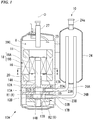
- a compressor 10 according to an embodiment of the present invention will be described with reference to FIGS. 1 to 3 .
- a compressor 10 according to the present embodiment includes a motor 18 which is driven by an external power supply, a compression mechanism 10A which is driven by the motor 18 to compress a refrigerant, and a housing 11 which covers the motor 18 and the compression mechanism 10A.
- the compression mechanism 10A includes a crankshaft 16 which is rotated by the motor 18, piston rotors 13A and 13B which are eccentrically rotated according to the rotation of the crankshaft 16, and cylinders 12A and 12B in which a compression chamber for accommodating the piston rotors 13A and 13B is formed.
- the compression mechanism 10A is a so-called two-cylinder type rotary compressor in which the disk-shaped cylinders 12A and 12B are provided in two stages in the cylindrical housing 11 in upper and lower stages.
- the housing 11 surrounds the cylinders 12A and 12B, and thus, forms a discharge space V through which a compressed refrigerant is discharged.
- the cylindrical piston rotors 13A and 13B each having an outer shape smaller than an inside of a cylinder inner wall surface are disposed inside the cylinders 12A and 12B.
- the piston rotors 13A and 13B are inserted into and fixed to eccentric shaft portions 14A and 14B of a rotating shaft along a central axis of the housing 11, respectively.
- the piston rotor 13A of the upper stage-side cylinder and the piston rotor 13B of the lower stage-side cylinder are provided so that phases thereof are different from each other by 180°.
- a disk-shaped partition plate 15 is provided between the upper and lower cylinders 12A and 12B.
- a space R in the upper stage-side cylinder 12A and the lower stage-side space R do not communicate with each other and are partitioned into compression chambers R1 and R2 by the partition plate 15.
- the crankshaft 16 is rotatably supported around an axis O by an upper bearing portion 17A fixed to the cylinder 12A and a lower bearing portion 17B fixed to the cylinder 12B.
- the crankshaft 16 has the eccentric shaft portions 14A and 14B which are offset in a direction orthogonal to a center line of the crankshaft 16.
- the eccentric shaft portions 14A and 14B turn around the central axis of the crankshaft 16, and thus, the upper and lower piston rotors 13A and 13B follow the turning and eccentrically rotate in the cylinders 12A and 12B.
- crankshaft 16 protrudes upward (that is, a direction in which the motor 18 is located when viewed from the compression mechanism 10A) from the upper bearing portion 17A.
- a rotor 19A of the motor 18 for rotationally driving the crankshaft 16 is integrally provided at one end portion of the crankshaft 16 in a direction of the axis O.
- a stator 19B is fixed to an inner peripheral surface of the housing 11 so as to face an outer peripheral portion of the rotor 19A.
- an accumulator 24 for performing gas-liquid separation on the refrigerant before the refrigerant is supplied to the compressor 10 is fixed to the housing 11 via a stay 25.
- the accumulator 24 includes suction pipes 26A and 26B for sucking the refrigerant in the accumulator 24 into the compressor 10. Distal end portions of the suction pipes 26A, 26B are connected to suction ports 23A, 23B through openings 22A, 22B.
- the compressor 10 takes the refrigerant into the accumulator 24 from the suction opening 24a of the accumulator 24. Specifically, the refrigerant is separated into gas and liquid in the accumulator 24, and the gas is supplied from the suction pipes 26A and 26B to the compression chambers R1 and R2 which are internal spaces of the cylinders 12A and 12B through the suction ports 23A and 23B of the cylinders 12A and 12B.
- the piston rotors 13A and 13B are eccentrically rotated, and thus, volumes of the compression chambers R1 and R2 gradually decrease, and the refrigerant is compressed. After the refrigerant passes around the motor 18, the refrigerant is discharged to a pipe 27 constituting a refrigeration cycle via a discharge port provided at an upper portion.
- the motor 18 has the rotor 19A which is rotatable around the axis O, and the stator 19B which surrounds the rotor 19A about the axis O from an outer peripheral side.
- the rotor 19A is provided at an upper end portion of the crankshaft 16.
- the rotor 19A has a permanent magnet therein, and an outer shape of the rotor 19A is a substantially cylindrical shape about the axis O.
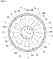
- FIG. 2 is a cross-sectional view taken along line A-A of FIG. 1 , and shows a detailed configuration of the stator 19B viewed in a direction of the axis O.
- the stator 19B includes a stator core 20 and a coil 20C.
- the stator core 20 is formed in a cylindrical shape about the axis O, and includes a yoke 20A of which an outer peripheral surface is fixed to an inner peripheral surface of the housing 11 and a plurality of teeth 20B which are formed at intervals in a circumferential direction of the yoke 20A so as to protrude from an inner peripheral surface of the yoke 20A.
- a plurality of electromagnetic steel sheets are stacked in a vertical direction, and thus, the stator core 20 is configured.
- a plurality of coils 20C are provided so as to correspond to each of the teeth 20B and are wound around each of the teeth 20B. Accordingly, the plurality of coils 20C are provided at intervals in the circumferential direction.
- the yoke 20A has a regular polygonal shape when viewed in the direction of the axis O.
- the yoke 20A has a regular nonagonal shape.
- Each apex angle of the yoke 20A is chamfered in an arc shape so as to conform to the inner peripheral surface of the housing 11.
- the chamfered portion is interference-fitted to the inner peripheral surface of the housing 11 to form an abutment portion T1.
- the stator core 20 is shrink-fitted to the housing 11, and thus, the abutment portion T1 is formed. That is, after the housing 11 is heated by a burner or the like and is expanded, the stator core 20 is inserted from an opening portion.
- an interference that is, deformation of the abutment portion T1 in a radial direction of the axis O
- an interference that is, deformation of the abutment portion T1 in a radial direction of the axis O
- a forming method thereof is not limited to the above-described shrink fitting, and cold fitting can be also used in which after the stator core 20 is cooled and shrunk, the stator core 20 is inserted into the housing 11.
- the outer diameter d1 refers to a length of a straight line obtained by connecting an outermost peripheral portion of one abutment portion T1, the axis O (a center of the yoke 20A), and the inner peripheral surface of the housing 11 facing the abutment portion T1 across the axis O to each other.
- a portion (a side portion of a regular nonagon) between a pair of abutment portions T1 and T1 adjacent to each other is separated from the inner peripheral surface of the housing 11 to be a non-abutment portion T2.
- the non-abutment portion T2 is a linear portion of the outer peripheral portion of the yoke 20A.
- the abutment portion T1 and the non-abutment portion T2 are continuously connected to each other. In other words, no step or the like is formed between the abutment portion T1 and the non-abutment portion T2.
- a slight gap is formed between the non-abutment portion T2 and a portion of the inner peripheral surface of the housing 11 facing the non-abutment portion T2. This gap serves as a flow path for high-pressure air generated by the compression mechanism 10A to flow upward.
- Each of the teeth 20B has a substantially plate shape extending in the radial direction of the axis O.
- Each of the teeth 20B is integrally formed of the same material as the yoke 20A. Width dimensions of the teeth 20B (that is, dimensions in the circumferential direction of the axis O) are constant over an entire area in the radial direction of the axis O.
- the plurality of teeth 20B are provided on the inner peripheral surface of the yoke 20A at equal intervals in the circumferential direction of the axis O.
- the stator core 20 according to the present embodiment has nine teeth 20B. Each of the teeth 20B is provided radially inside the non-abutment portion T2 of the yoke 20A.
- positions of the abutment portion T1 and the teeth 20B in the circumferential direction of the axis O are different from each other. Further, each of the teeth 20B is provided at a central portion of the non-abutment portion T2 when viewed in the direction of the axis O.
- a round section R having a curved shape (arc shape) when viewed in the direction of the axis O is formed at a connection portion between a radially outer end portion of each of the teeth 20B and the yoke 20A.
- a curvature radius of the round section R is 1.5 mm or less. It is more preferable that the curvature radius of the round section R is 0.5 mm or less.
- a flange portion B for holding a copper wire of the coil 20C is provided at a radially inner end portion of each of the teeth 20B.
- the flange portion B has a circumferential dimension larger than that of each of the teeth 20B.
- An inner peripheral surface of the flange portion B faces the above-described rotor 19A with a gap.
- a radially inner end surface of the flange portion B has an arc shape about a position of the axis O.
- the inner diameter d2 of the stator core 20 indicates a diameter of an imaginary circle formed by arcs of the plurality of flange portions B. d 2 / d 1 ⁇ 0.44
- the length L of the abutment portion T1 is kept small, and thus, a large length of the adjacent non-abutment portion T2 can be secured. That is, the gap between the non-abutment portion T2 and a portion of the inner peripheral surface of the housing 11 facing the non-abutment portion T2 can be increased. This gap serves as a flow path for high-pressure air generated by the compression mechanism 10A to flow upward. Therefore, the high-pressure air can be more smoothly introduced.
- the slot area refers to a cross-sectional area occupied by a copper wire portion in a total cross-sectional area of the coil 20C.
- the curvature radius of the round section R formed in the connection portion between the inner peripheral surface of the yoke 20A and the end portion of each of the teeth 20B is kept small. Accordingly, winding collapse of the coil 20C can be prevented.
- the slot area can be further increased and the efficiency of the motor 18 can increase.
- stator core 20 can be more firmly and stably fixed to the housing 11.
- the large plate thickness t of the housing 11 can be secured, and thus, strength and a pressure resistance of the housing 11 can be further increased.
- the embodiment of the present invention is described with reference to the drawings.
- the above configuration is an example, and various changes can be made to this configuration.
- a configuration in which nine teeth 20B are provided has been described.
- the number of teeth 20B is not limited to nine, and various numbers can be adopted according to a design and specifications.
- the shape of the yoke 20A is not limited to the above-described regular nonagonal shape, and may be another regular polygonal shape.
- the shape of the yoke 20A is not limited to a regular polygonal shape, and may be a non-equilateral polygonal shape.
- the lengths of contacts between the abutment portions T1 and the inner peripheral surface of the housing 11 are non-uniform.
- the value of the contact length L is the total value of the lengths of all the abutment portions T1 as described above.
- the present invention can be applied to a compressor including a motor which includes a rotor rotatable around an axis and a stator core surrounding the rotor from an outer peripheral side about the axis, a compression mechanism which is driven by the motor to compress a refrigerant, and a housing which covers the motor and the compression mechanism.
- a motor which includes a rotor rotatable around an axis and a stator core surrounding the rotor from an outer peripheral side about the axis
- a compression mechanism which is driven by the motor to compress a refrigerant
- a housing which covers the motor and the compression mechanism.
Landscapes
- Engineering & Computer Science (AREA)
- Mechanical Engineering (AREA)
- General Engineering & Computer Science (AREA)
- Power Engineering (AREA)
- Iron Core Of Rotating Electric Machines (AREA)
- Compressor (AREA)
- Applications Or Details Of Rotary Compressors (AREA)
Abstract
Description
- The present invention relates to a compressor.
- Priority is claimed on Japanese Patent Application No.
2017-144508 filed on July 26, 2017 - A rotary compressor is known as one type of a compressor used in an air conditioner. The rotary compressor includes a motor which is driven by an external power supply and a compressor main body which is connected to an output shaft of the motor. The compressor main body includes a crankshaft which is rotationally driven by the output shaft, a piston rotor which is provided integrally with the crankshaft, and a cylinder which covers the piston rotor. The piston rotor eccentrically rotates at a position different from the output shaft in the cylinder, and thus, air in the cylinder is compressed and high-pressure compressed air is generated.
- For example, as a specific example of a motor (electric motor) for the rotary compressor, a motor described in
Patent Literature 1 below is known. The motor described inPatent Literature 1 includes a rotor which is provided on an output shaft, and a substantially annular stator core (stator) to which a plurality of coils covering the rotor from an outer peripheral side are attached. An outer peripheral surface of the stator core is interference-fitted to an inner peripheral surface of a housing of a rotary compressor through processing such as shrink fitting. - [Patent Document 1] Japanese Unexamined Patent Application, First Publication No.
2008-271616 - Here, in recent years, attention has been focused on improving efficiency of a motor as one measure for improving efficiency of a compressor. Copper loss and iron loss are mainly known as factors which hinder improvement in efficiency of a motor. The copper loss is an energy loss caused by a resistance component of a copper wire constituting a coil. Moreover, the iron loss is an energy loss caused by physical properties and a shape of a stator core around which a coil is wound. Generally, a thicker copper wire is used for a coil, and thus, the copper loss can be reduced, and efficiency of the motor can increase. However, as a thickness of the copper wire increases, a cross-sectional area (width) of the stator core is reduced. Accordingly, concentration of compressive stress exerted on the stator core by the housing is likely to occur in a state where the stator core is interference-fitted. As a result, iron loss of the stator core increases, and effects of reducing copper loss may be impaired. That is, there is a possibility that it is difficult to increase the efficiency of the motor.
- The present invention is made to solve the above problems, and an object thereof is to provide a compressor having a more efficient motor.
- According to a first aspect of the present invention, there is provided a compressor including: a motor which includes a rotor rotatable around an axis and a stator core surrounding the rotor from an outer peripheral side about the axis; a compression mechanism which is driven by the motor to compress a refrigerant; and a housing which covers the motor and the compression mechanism, in which a plurality of abutment portions which are interference-fitted to an inner peripheral surface of the housing and a plurality of non-abutment portions which are respectively provided to be adjacent to the abutment portions and are separated from the inner peripheral surface are formed on an outer peripheral surface of the stator core, and if a total length of the plurality of abutment portions is L and an outer diameter of the stator core is d1 when viewed in a direction of the axis, a relationship of Expression (1) is satisfied.

- According to this configuration, the total length of the abutment portions is kept small. Therefore, compressive stress that the abutment portions receive from the housing can be reduced. Accordingly, an iron loss generated in the stator core can be reduced.
- According to a second aspect of the present invention, in the compressor, if the total length of the plurality of abutment portions is L and the outer diameter of the stator core is d1 when viewed in the direction of the axis, a relationship of Expression (2) may be satisfied.

- According to this configuration, the total length of the abutment portions is kept smaller. Therefore, the compressive stress that the abutment portions receive from the housing can be reduced. Accordingly, the iron loss generated in the stator core can be further reduced.
- According to a third aspect of the present invention, if the total length of the plurality of abutment portions is L and the outer diameter of the stator core is d1 when viewed in the direction of the axis, a relationship of Expression (3) may be satisfied.

- According to this configuration, the total length of the abutment portions is kept smaller. Therefore, the compressive stress that the abutment portions receive from the housing can be reduced. Accordingly, the iron loss generated in the stator core can be further reduced.
- According to a fourth aspect of the present invention, the stator core may include an annular yoke having the abutment portions and the non-abutment portions and a plurality of teeth extending radially inward of the axis from an inner peripheral surface of the yoke, and when a dimension of the yoke in a radial direction of the axis is w, a relationship of Expression (4) may be satisfied.

- According to this configuration, a size of the yoke is kept small. Therefore, a large slot area of the motor can be secured. Accordingly, efficiency of the motor can increase. Moreover, the slot area refers to a cross-sectional area occupied by a copper wire portion in a total cross-sectional area of the coil.
- According to a fifth aspect of the present invention, if a length of the yoke in a direction orthogonal to the radial direction is w when viewed in the direction of the axis, a relationship of Expression (5) may be satisfied.

- According to this configuration, the size of the yoke is kept small. Therefore, a larger slot area of the motor can be secured. Accordingly, the efficiency of the motor can further increase. Moreover, the slot area refers to the cross-sectional area occupied by the copper wire portion in the total cross-sectional area of the coil.
- According to a sixth aspect of the present invention, the stator core may include an annular yoke having the abutment portions and the non-abutment portions and teeth extending radially inward of the axis from an inner peripheral surface of the yoke, and when viewed in the direction of the axis, a curved round section may be formed in a connection portion between the inner peripheral surface of the yoke and radially outer end portions of the teeth and a curvature radius of the round section may be 1.5 mm or less.
- According to this configuration, the curvature radius of the round section formed in the connection portion between the inner peripheral surface of the yoke and the end portions of the teeth is kept small. Accordingly, winding collapse of the coil can be prevented. In addition, the slot area can be further increased and the efficiency of the motor can increase.
- According to a seventh aspect of the present invention, the curvature radius of the round section may be 0.5 mm or less.
- According to this configuration, the winding collapse of the coil can be prevented. Moreover, the slot area can be further increased and the efficiency of the motor can increase.
- According to an eighth aspect of the present invention, when an inner diameter of the stator core is d2, a relationship of Expression (6) may be satisfied.

- According to this configuration, the inner diameter of the stator core is kept small. Therefore, a large outer diameter of the rotor can be secured. Moreover, the slot area can be increased. Therefore, the efficiency of the motor can increase.
- According to a ninth aspect of the present invention, when the inner diameter of the stator core is d2, a relationship of Expression (7) may be satisfied.

- According to this configuration, the inner diameter of the stator core is kept smaller. Therefore, a larger outer diameter of the rotor can be secured. Moreover, the slot area can be increased. Therefore, the efficiency of the motor can increase.
- According to a tenth aspect of the present invention, an interference of the stator core with respect to the housing may be 0.05 mm or more.
- According to this configuration, the large interference can be secured. Therefore, the stator core can be more firmly and stably fixed to the housing.
- According to an eleventh aspect of the present invention, when a plate thickness of the housing is t, a relationship of Expression (8) may be satisfied.

- According to this configuration, the large plate thickness of the housing can be secured. Therefore, strength and a pressure resistance of the housing can be further increased.
- According to the present invention, it is possible to provide a compressor including a more efficient motor.
-
-
FIG. 1 is a cross-sectional view showing a configuration of a compressor according to an embodiment of the present invention. -
FIG. 2 is a cross-sectional view taken along line A-A ofFIG. 1 . -
FIG. 3 is an enlarged view of a main portion ofFIG. 2 . -
FIG. 4 is a table showing a relationship between a value of L/dl, an iron loss, a copper loss, and a motor efficiency according to an example of the present invention. - A
compressor 10 according to an embodiment of the present invention will be described with reference toFIGS. 1 to 3 . As shown inFIG. 1 , acompressor 10 according to the present embodiment includes amotor 18 which is driven by an external power supply, acompression mechanism 10A which is driven by themotor 18 to compress a refrigerant, and ahousing 11 which covers themotor 18 and thecompression mechanism 10A. - The
compression mechanism 10A includes acrankshaft 16 which is rotated by themotor 18,piston rotors crankshaft 16, andcylinders 12A and 12B in which a compression chamber for accommodating thepiston rotors - The
compression mechanism 10A is a so-called two-cylinder type rotary compressor in which the disk-shapedcylinders 12A and 12B are provided in two stages in thecylindrical housing 11 in upper and lower stages. Thehousing 11 surrounds thecylinders 12A and 12B, and thus, forms a discharge space V through which a compressed refrigerant is discharged. Thecylindrical piston rotors cylinders 12A and 12B. Thepiston rotors eccentric shaft portions housing 11, respectively. - The
piston rotor 13A of the upper stage-side cylinder and thepiston rotor 13B of the lower stage-side cylinder are provided so that phases thereof are different from each other by 180°. - In addition, a disk-shaped
partition plate 15 is provided between the upper andlower cylinders 12A and 12B. A space R in the upper stage-side cylinder 12A and the lower stage-side space R do not communicate with each other and are partitioned into compression chambers R1 and R2 by thepartition plate 15. - The
crankshaft 16 is rotatably supported around an axis O by anupper bearing portion 17A fixed to thecylinder 12A and alower bearing portion 17B fixed to the cylinder 12B. - The
crankshaft 16 has theeccentric shaft portions crankshaft 16. Theeccentric shaft portions crankshaft 16, and thus, the upper andlower piston rotors cylinders 12A and 12B. - The
crankshaft 16 protrudes upward (that is, a direction in which themotor 18 is located when viewed from thecompression mechanism 10A) from theupper bearing portion 17A. Arotor 19A of themotor 18 for rotationally driving thecrankshaft 16 is integrally provided at one end portion of thecrankshaft 16 in a direction of the axis O. Astator 19B is fixed to an inner peripheral surface of thehousing 11 so as to face an outer peripheral portion of therotor 19A. - In the
compressor 10, anaccumulator 24 for performing gas-liquid separation on the refrigerant before the refrigerant is supplied to thecompressor 10 is fixed to thehousing 11 via astay 25. Theaccumulator 24 includessuction pipes accumulator 24 into thecompressor 10. Distal end portions of thesuction pipes ports openings - The
compressor 10 takes the refrigerant into theaccumulator 24 from thesuction opening 24a of theaccumulator 24. Specifically, the refrigerant is separated into gas and liquid in theaccumulator 24, and the gas is supplied from thesuction pipes cylinders 12A and 12B through thesuction ports cylinders 12A and 12B. - In addition, the
piston rotors motor 18, the refrigerant is discharged to apipe 27 constituting a refrigeration cycle via a discharge port provided at an upper portion. - The
motor 18 has therotor 19A which is rotatable around the axis O, and thestator 19B which surrounds therotor 19A about the axis O from an outer peripheral side. Therotor 19A is provided at an upper end portion of thecrankshaft 16. Therotor 19A has a permanent magnet therein, and an outer shape of therotor 19A is a substantially cylindrical shape about the axis O. -
FIG. 2 is a cross-sectional view taken along line A-A ofFIG. 1 , and shows a detailed configuration of thestator 19B viewed in a direction of the axis O. (In addition, therotor 19A is not shown inFIG. 2 for simplicity.) As shown inFIG. 2 , thestator 19B includes astator core 20 and acoil 20C. Thestator core 20 is formed in a cylindrical shape about the axis O, and includes ayoke 20A of which an outer peripheral surface is fixed to an inner peripheral surface of thehousing 11 and a plurality ofteeth 20B which are formed at intervals in a circumferential direction of theyoke 20A so as to protrude from an inner peripheral surface of theyoke 20A. A plurality of electromagnetic steel sheets are stacked in a vertical direction, and thus, thestator core 20 is configured. A plurality ofcoils 20C are provided so as to correspond to each of theteeth 20B and are wound around each of theteeth 20B. Accordingly, the plurality ofcoils 20C are provided at intervals in the circumferential direction. - The
yoke 20A has a regular polygonal shape when viewed in the direction of the axis O. In the present embodiment, theyoke 20A has a regular nonagonal shape. Each apex angle of theyoke 20A is chamfered in an arc shape so as to conform to the inner peripheral surface of thehousing 11. The chamfered portion is interference-fitted to the inner peripheral surface of thehousing 11 to form an abutment portion T1. Thestator core 20 is shrink-fitted to thehousing 11, and thus, the abutment portion T1 is formed. That is, after thehousing 11 is heated by a burner or the like and is expanded, thestator core 20 is inserted from an opening portion. In this case, an interference (that is, deformation of the abutment portion T1 in a radial direction of the axis O) of the abutment portion T1 with respect to thehousing 11 is 0.05 mm or more. Moreover, when the abutment portion T1 is formed, a forming method thereof is not limited to the above-described shrink fitting, and cold fitting can be also used in which after thestator core 20 is cooled and shrunk, thestator core 20 is inserted into thehousing 11. - When viewed in the direction of the axis O, if a total length (a sum of contact lengths of the
housing 11 and theyoke 20A) of the lengths of all (nine) abutment portions T1 is L and an outer diameter of theyoke 20A is d1, a relationship of the following Expression (1) is established between L and d1. Moreover, as shown inFIG. 2 , here, the outer diameter d1 refers to a length of a straight line obtained by connecting an outermost peripheral portion of one abutment portion T1, the axis O (a center of theyoke 20A), and the inner peripheral surface of thehousing 11 facing the abutment portion T1 across the axis O to each other. InFIG. 3 , only one abutment portion T1 is shown, and a length of the one abutment portion T1 is represented as L/9. That is, the contact length L is a total value of lengths of the nine abutment portions T1 (L = L/9 × 9).
- Further, it is more preferable that the values of L and d1 satisfy a relationship of Expression (2).

- In addition, it is most preferable that the values of L and d1 satisfy a relationship of Expression (3).

- Moreover, when a width dimension (a dimension in the radial direction of the axis O) of the
yoke 20A is w, the following Expression (4) is established between w and the above-described outer diameter d1.
- Moreover, it is more preferable that the values of w and d1 satisfy a relationship of Expression (5).

- A portion (a side portion of a regular nonagon) between a pair of abutment portions T1 and T1 adjacent to each other is separated from the inner peripheral surface of the
housing 11 to be a non-abutment portion T2. The non-abutment portion T2 is a linear portion of the outer peripheral portion of theyoke 20A. The abutment portion T1 and the non-abutment portion T2 are continuously connected to each other. In other words, no step or the like is formed between the abutment portion T1 and the non-abutment portion T2. A slight gap is formed between the non-abutment portion T2 and a portion of the inner peripheral surface of thehousing 11 facing the non-abutment portion T2. This gap serves as a flow path for high-pressure air generated by thecompression mechanism 10A to flow upward. - Each of the
teeth 20B has a substantially plate shape extending in the radial direction of the axis O. Each of theteeth 20B is integrally formed of the same material as theyoke 20A. Width dimensions of theteeth 20B (that is, dimensions in the circumferential direction of the axis O) are constant over an entire area in the radial direction of the axis O. The plurality ofteeth 20B are provided on the inner peripheral surface of theyoke 20A at equal intervals in the circumferential direction of the axis O. Thestator core 20 according to the present embodiment has nineteeth 20B. Each of theteeth 20B is provided radially inside the non-abutment portion T2 of theyoke 20A. In other words, positions of the abutment portion T1 and theteeth 20B in the circumferential direction of the axis O are different from each other. Further, each of theteeth 20B is provided at a central portion of the non-abutment portion T2 when viewed in the direction of the axis O. - As shown in
FIG. 3 , a round section R having a curved shape (arc shape) when viewed in the direction of the axis O is formed at a connection portion between a radially outer end portion of each of theteeth 20B and theyoke 20A. A curvature radius of the round section R is 1.5 mm or less. It is more preferable that the curvature radius of the round section R is 0.5 mm or less. - A flange portion B for holding a copper wire of the
coil 20C is provided at a radially inner end portion of each of theteeth 20B. The flange portion B has a circumferential dimension larger than that of each of theteeth 20B. An inner peripheral surface of the flange portion B faces the above-describedrotor 19A with a gap. A radially inner end surface of the flange portion B has an arc shape about a position of the axis O. - Here, when an inner diameter of the
stator core 20 is d2, the following Expression (6) is established between d2 and the above-described outer diameter d1. In addition, here, the inner diameter d2 of thestator core 20 indicates a diameter of an imaginary circle formed by arcs of the plurality of flangeportions B. 
- Moreover, it is more preferable that the values of d1 and d2 satisfy a relationship of Expression (7).

- Further, when a plate thickness of the
housing 11 is t, a relationship of the following Expression (8) is established between t and the above-described outer diameter d1.
- According to the above-described configuration, the relationship of Expression (1), Expression (2), or Expression (3) is established between the length L of the abutment portion T1 and the outer diameter d1 of the
stator core 20. Accordingly, the length of the abutment portion T1 is kept small, and thus, compressive stress that the abutment portion T1 receives from thehousing 11 can be reduced. Thereby, an iron loss generated in thestator core 20 when themotor 18 is driven can be reduced. - According to the above-described configuration, the length L of the abutment portion T1 is kept small, and thus, a large length of the adjacent non-abutment portion T2 can be secured. That is, the gap between the non-abutment portion T2 and a portion of the inner peripheral surface of the
housing 11 facing the non-abutment portion T2 can be increased. This gap serves as a flow path for high-pressure air generated by thecompression mechanism 10A to flow upward. Therefore, the high-pressure air can be more smoothly introduced. - According to the above-described configuration, when the dimension of the
yoke 20A in the radial direction of the axis O is w, the relationship of Expression (4) or Expression (5) is established. Accordingly, a size of theyoke 20A is kept small, and thus, a large slot area of themotor 18 can be secured. Thus, efficiency of themotor 18 can increase. Moreover, the slot area refers to a cross-sectional area occupied by a copper wire portion in a total cross-sectional area of thecoil 20C. - According to the above-described configuration, the curvature radius of the round section R formed in the connection portion between the inner peripheral surface of the
yoke 20A and the end portion of each of theteeth 20B is kept small. Accordingly, winding collapse of thecoil 20C can be prevented. In addition, the slot area can be further increased and the efficiency of themotor 18 can increase. - According to the above-described configuration, when the inner diameter of the
stator core 20 is d2, the relationship of Expression (6) or Expression (7) is established. The inner diameter of thestator core 20 is kept small, and thus, a large outer diameter of therotor 19A can be secured. Moreover, the slot area can be increased, and thus, the efficiency of themotor 18 can increase. - According to the above-described configuration, a large interference of the
stator core 20 with respect to thehousing 11 can be secured, and thus, thestator core 20 can be more firmly and stably fixed to thehousing 11. - According to the above-described configuration, the large plate thickness t of the
housing 11 can be secured, and thus, strength and a pressure resistance of thehousing 11 can be further increased. - Hereinbefore, the embodiment of the present invention is described with reference to the drawings. In addition, the above configuration is an example, and various changes can be made to this configuration. For example, in the above embodiment, a configuration in which nine
teeth 20B are provided has been described. However, the number ofteeth 20B is not limited to nine, and various numbers can be adopted according to a design and specifications. Moreover, the shape of theyoke 20A is not limited to the above-described regular nonagonal shape, and may be another regular polygonal shape. In addition, the shape of theyoke 20A is not limited to a regular polygonal shape, and may be a non-equilateral polygonal shape. In this case, the lengths of contacts between the abutment portions T1 and the inner peripheral surface of thehousing 11 are non-uniform. However, the value of the contact length L is the total value of the lengths of all the abutment portions T1 as described above. - Hereinafter, examples of the present invention will be described with reference to a table shown in
FIG. 4 . As shown in the table, the inventors changed a value of a ratio (L/dl) between the contact length L of the abutment portion T1 and the outer diameter d1 of thestator core 20 to investigate changes of the Iron loss, the copper loss, and the motor efficiency before the shrink fitting and after the shrink fitting (Cases 1 to 3). - As shown as a comparative example in
Case 1 ofFIG. 4 , in a case where L/dl does not satisfy the relationship of the above-described Expression (1) (L/dl = 1.36), when each of the iron loss, the copper loss, and the motor efficiency was 100% before the shrink fitting was performed, the iron loss was 160.3% and the copper loss was 102.4%. Further, the motor efficiency was 98.5%. Further, as shown as a comparative example inCase 2, in a case where L/dl = 1.84, the iron loss was 145.6% and the copper loss was 105.3%. The motor efficiency was 98.7%. - Meanwhile, as shown in
Case 3, in a case where L/dl satisfies the relationship of the above-described Expression (1) (L/dl = 0.34), the iron loss was 106.4% and the copper loss was 102.2%. The motor efficiency was 99.8%. Accordingly, it is found that inCase 3, all of the iron loss, copper loss, and motor efficiency are improved as compared toCases - Moreover, in recent years, when the motor efficiency is improved, generally, an increase in efficiency obtained by one improvement is in a range of at most 0.1% or a little more. However, as described above, according to the configurations of the above-described embodiment and the present comparative example, it is possible to significantly improve the motor efficiency by about 1%.
- The present invention can be applied to a compressor including a motor which includes a rotor rotatable around an axis and a stator core surrounding the rotor from an outer peripheral side about the axis, a compression mechanism which is driven by the motor to compress a refrigerant, and a housing which covers the motor and the compression mechanism. According to the compressor of the present invention, the efficiency of the compressor can increase.
-
- 10: compressor
- 10A: compression mechanism
- 11: housing
- 12A, 12B: cylinder
- 13A, 13B: piston rotor
- 16: crankshaft
- 18: motor
- 19A: rotor
- 19B: stator
- 20: stator core
- 20A: yoke
- 20B: teeth
- 20C: coil
- 22A, 22B: opening
- 23A, 23B: suction port
- 24: accumulator
- 25: stay
- 26A, 26B: suction pipe
- 27: pipe
- B: flange portion
- O: axis
- R: round section
Claims (11)
- A compressor comprising:a motor which includes a rotor rotatable around an axis and a stator core surrounding the rotor from an outer peripheral side about the axis;a compression mechanism which is driven by the motor to compress a refrigerant; anda housing which covers the motor and the compression mechanism,wherein a plurality of abutment portions which are interference-fitted to an inner peripheral surface of the housing and a plurality of non-abutment portions which are respectively provided to be adjacent to the abutment portions and are separated from the inner peripheral surface are formed on an outer peripheral surface of the stator core, andwherein if a total length of the plurality of abutment portions is L and an outer diameter of the stator core is d1 when viewed in a direction of the axis, a relationship of Expression (1) is satisfied.

- The compressor according to claim 1,
wherein if the total length of the plurality of abutment portions is L and the outer diameter of the stator core is d1 when viewed in the direction of the axis, a relationship of Expression (2) is satisfied.
- The compressor according to claim 1 or 2,
wherein if the total length of the plurality of abutment portions is L and the outer diameter of the stator core is d1 when viewed in the direction of the axis, a relationship of Expression (3) is satisfied.
- The compressor according to any one of claims 1 to 3,
wherein the stator core includes an annular yoke having the abutment portions and the non-abutment portions and a plurality of teeth extending radially inward of the axis from an inner peripheral surface of the yoke, and
wherein when a dimension of the yoke in a radial direction of the axis is w, a relationship of Expression (4) is satisfied.
- The compressor according to claim 4,
wherein if a length of the yoke in a direction orthogonal to the radial direction is w when viewed in the direction of the axis, a relationship of Expression (5) is satisfied.
- The compressor according to any one of claims 1 to 5,
wherein the stator core includes an annular yoke having the abutment portions and the non-abutment portions and teeth extending radially inward of the axis from an inner peripheral surface of the yoke, and
wherein when viewed in the direction of the axis, a curved round section is formed in a connection portion between the inner peripheral surface of the yoke and radially outer end portions of the teeth and a curvature radius of the round section is 1.5 mm or less. - The compressor according to claim 6,
wherein the curvature radius of the round section is 0.5 mm or less. - The compressor according to any one of claims 1 to 7,
wherein when an inner diameter of the stator core is d2, a relationship of Expression (6) is satisfied.
- The compressor according to claim 8,
wherein when the inner diameter of the stator core is d2, a relationship of Expression (7) is satisfied.
- The compressor according to any one of claims 1 to 9,
wherein an interference of the stator core with respect to the housing is 0.05 mm or more. - The compressor according to any one of claims 1 to 10,
wherein when a plate thickness of the housing is t, a relationship of Expression (8) is satisfied.
Applications Claiming Priority (2)
| Application Number | Priority Date | Filing Date | Title |
|---|---|---|---|
| JP2017144508A JP7067880B2 (en) | 2017-07-26 | 2017-07-26 | Compressor |
| PCT/JP2018/022341 WO2019021658A1 (en) | 2017-07-26 | 2018-06-12 | Compressor |
Publications (3)
| Publication Number | Publication Date |
|---|---|
| EP3661020A1 true EP3661020A1 (en) | 2020-06-03 |
| EP3661020A4 EP3661020A4 (en) | 2020-07-15 |
| EP3661020B1 EP3661020B1 (en) | 2021-08-11 |
Family
ID=65040701
Family Applications (1)
| Application Number | Title | Priority Date | Filing Date |
|---|---|---|---|
| EP18837784.0A Active EP3661020B1 (en) | 2017-07-26 | 2018-06-12 | Compressor |
Country Status (4)
| Country | Link |
|---|---|
| EP (1) | EP3661020B1 (en) |
| JP (1) | JP7067880B2 (en) |
| AU (1) | AU2018306257B2 (en) |
| WO (1) | WO2019021658A1 (en) |
Families Citing this family (3)
| Publication number | Priority date | Publication date | Assignee | Title |
|---|---|---|---|---|
| CN112713672B (en) * | 2019-10-25 | 2022-03-22 | 佛山市威灵洗涤电机制造有限公司 | Motor and its assembly structure |
| JPWO2023112078A1 (en) * | 2021-12-13 | 2023-06-22 | ||
| DE102023102466A1 (en) | 2023-02-01 | 2024-08-01 | Dr. Ing. H.C. F. Porsche Aktiengesellschaft | Electrical machine, manufacture and use thereof and motor vehicle with such a machine |
Family Cites Families (9)
| Publication number | Priority date | Publication date | Assignee | Title |
|---|---|---|---|---|
| JPS5999669U (en) * | 1982-12-24 | 1984-07-05 | 株式会社日立製作所 | liquid general pump |
| JPH0296494U (en) * | 1989-01-19 | 1990-08-01 | ||
| JP4036148B2 (en) * | 2002-07-23 | 2008-01-23 | 株式会社豊田自動織機 | Electric motor and electric compressor |
| US20070114874A1 (en) * | 2005-11-23 | 2007-05-24 | Daewoo Electronics Corporation | Motor having a stator and a rotor made of soft magnetic powder material |
| JP2007244150A (en) * | 2006-03-10 | 2007-09-20 | Toyota Industries Corp | Electric motor and motor-driven compressor |
| JP2008271616A (en) | 2007-04-16 | 2008-11-06 | Toshiba Carrier Corp | Hermetic compressor and refrigeration cycle apparatus using the same |
| JP4623217B2 (en) | 2008-08-06 | 2011-02-02 | 株式会社デンソー | Fuel supply pump |
| JP2015002650A (en) * | 2013-06-18 | 2015-01-05 | ダイキン工業株式会社 | Motor and compressor employing the same |
| JP6581011B2 (en) | 2016-02-17 | 2019-09-25 | Kyb株式会社 | Centering device |
-
2017
- 2017-07-26 JP JP2017144508A patent/JP7067880B2/en active Active
-
2018
- 2018-06-12 AU AU2018306257A patent/AU2018306257B2/en active Active
- 2018-06-12 WO PCT/JP2018/022341 patent/WO2019021658A1/en not_active Ceased
- 2018-06-12 EP EP18837784.0A patent/EP3661020B1/en active Active
Also Published As
| Publication number | Publication date |
|---|---|
| EP3661020B1 (en) | 2021-08-11 |
| EP3661020A4 (en) | 2020-07-15 |
| JP2019030056A (en) | 2019-02-21 |
| WO2019021658A1 (en) | 2019-01-31 |
| AU2018306257B2 (en) | 2021-01-21 |
| AU2018306257A1 (en) | 2020-03-12 |
| JP7067880B2 (en) | 2022-05-16 |
Similar Documents
| Publication | Publication Date | Title |
|---|---|---|
| JP6584513B2 (en) | Rotor, rotating electrical machine, electric compressor and refrigeration air conditioner | |
| CN102545505B (en) | Induction motor, compressor and refrigerating circulatory device | |
| US10020699B2 (en) | Embedded permanent magnet type electric motor, compressor, and refrigeration air-conditioning device | |
| US9634531B2 (en) | Electric motor with embedded permanent magnet, compressor, and refrigeration/air-conditioning device | |
| EP2749735B1 (en) | Compressor | |
| EP3661020B1 (en) | Compressor | |
| EP3166208B1 (en) | Rotor, electric motor, compressor, and fan | |
| KR100581310B1 (en) | Multi-Cylinder Rotary Compressor | |
| WO2010016583A1 (en) | Stator, motor, and compressor | |
| JP2019115157A (en) | Stator for motor, motor, and rotary compressor | |
| KR100675549B1 (en) | Electric compressor | |
| KR102287164B1 (en) | Electric motor and compressor having the same | |
| JP5862332B2 (en) | Rotor and compressor | |
| US20070120434A1 (en) | Synchronous reluctance motor and compressor having the same | |
| JP2018102039A (en) | Electric motor rotor, compressor | |
| EP4407837B1 (en) | Rotating electric machine, compressor, and refrigerator device | |
| WO2017047338A1 (en) | Hermetic electric compressor | |
| JPWO2020208777A1 (en) | Compressor and motor for compressor | |
| JP2012036822A (en) | Compressor | |
| JP2012120365A (en) | Rotor, motor and compressor | |
| EP3550700B1 (en) | Stator, motor and compressor | |
| US10724525B2 (en) | Compression mechanism for a compressor | |
| EP4130478A1 (en) | Rotary compressor | |
| JP2008099380A (en) | Compressor motor and compressor | |
| JP2008271616A (en) | Hermetic compressor and refrigeration cycle apparatus using the same |
Legal Events
| Date | Code | Title | Description |
|---|---|---|---|
| STAA | Information on the status of an ep patent application or granted ep patent |
Free format text: STATUS: THE INTERNATIONAL PUBLICATION HAS BEEN MADE |
|
| PUAI | Public reference made under article 153(3) epc to a published international application that has entered the european phase |
Free format text: ORIGINAL CODE: 0009012 |
|
| STAA | Information on the status of an ep patent application or granted ep patent |
Free format text: STATUS: REQUEST FOR EXAMINATION WAS MADE |
|
| 17P | Request for examination filed |
Effective date: 20200224 |
|
| AK | Designated contracting states |
Kind code of ref document: A1 Designated state(s): AL AT BE BG CH CY CZ DE DK EE ES FI FR GB GR HR HU IE IS IT LI LT LU LV MC MK MT NL NO PL PT RO RS SE SI SK SM TR |
|
| AX | Request for extension of the european patent |
Extension state: BA ME |
|
| A4 | Supplementary search report drawn up and despatched |
Effective date: 20200615 |
|
| RIC1 | Information provided on ipc code assigned before grant |
Ipc: F04B 39/00 20060101ALI20200608BHEP Ipc: F04C 29/00 20060101ALI20200608BHEP Ipc: H02K 1/18 20060101AFI20200608BHEP Ipc: H02K 1/14 20060101ALI20200608BHEP |
|
| DAV | Request for validation of the european patent (deleted) | ||
| DAX | Request for extension of the european patent (deleted) | ||
| GRAP | Despatch of communication of intention to grant a patent |
Free format text: ORIGINAL CODE: EPIDOSNIGR1 |
|
| STAA | Information on the status of an ep patent application or granted ep patent |
Free format text: STATUS: GRANT OF PATENT IS INTENDED |
|
| INTG | Intention to grant announced |
Effective date: 20210303 |
|
| GRAS | Grant fee paid |
Free format text: ORIGINAL CODE: EPIDOSNIGR3 |
|
| GRAA | (expected) grant |
Free format text: ORIGINAL CODE: 0009210 |
|
| STAA | Information on the status of an ep patent application or granted ep patent |
Free format text: STATUS: THE PATENT HAS BEEN GRANTED |
|
| AK | Designated contracting states |
Kind code of ref document: B1 Designated state(s): AL AT BE BG CH CY CZ DE DK EE ES FI FR GB GR HR HU IE IS IT LI LT LU LV MC MK MT NL NO PL PT RO RS SE SI SK SM TR |
|
| REG | Reference to a national code |
Ref country code: CH Ref legal event code: EP |
|
| REG | Reference to a national code |
Ref country code: DE Ref legal event code: R096 Ref document number: 602018021837 Country of ref document: DE |
|
| REG | Reference to a national code |
Ref country code: IE Ref legal event code: FG4D Ref country code: AT Ref legal event code: REF Ref document number: 1420395 Country of ref document: AT Kind code of ref document: T Effective date: 20210915 |
|
| REG | Reference to a national code |
Ref country code: LT Ref legal event code: MG9D |
|
| REG | Reference to a national code |
Ref country code: NL Ref legal event code: MP Effective date: 20210811 |
|
| REG | Reference to a national code |
Ref country code: AT Ref legal event code: MK05 Ref document number: 1420395 Country of ref document: AT Kind code of ref document: T Effective date: 20210811 |
|
| PG25 | Lapsed in a contracting state [announced via postgrant information from national office to epo] |
Ref country code: HR Free format text: LAPSE BECAUSE OF FAILURE TO SUBMIT A TRANSLATION OF THE DESCRIPTION OR TO PAY THE FEE WITHIN THE PRESCRIBED TIME-LIMIT Effective date: 20210811 Ref country code: NO Free format text: LAPSE BECAUSE OF FAILURE TO SUBMIT A TRANSLATION OF THE DESCRIPTION OR TO PAY THE FEE WITHIN THE PRESCRIBED TIME-LIMIT Effective date: 20211111 Ref country code: PT Free format text: LAPSE BECAUSE OF FAILURE TO SUBMIT A TRANSLATION OF THE DESCRIPTION OR TO PAY THE FEE WITHIN THE PRESCRIBED TIME-LIMIT Effective date: 20211213 Ref country code: LT Free format text: LAPSE BECAUSE OF FAILURE TO SUBMIT A TRANSLATION OF THE DESCRIPTION OR TO PAY THE FEE WITHIN THE PRESCRIBED TIME-LIMIT Effective date: 20210811 Ref country code: BG Free format text: LAPSE BECAUSE OF FAILURE TO SUBMIT A TRANSLATION OF THE DESCRIPTION OR TO PAY THE FEE WITHIN THE PRESCRIBED TIME-LIMIT Effective date: 20211111 Ref country code: AT Free format text: LAPSE BECAUSE OF FAILURE TO SUBMIT A TRANSLATION OF THE DESCRIPTION OR TO PAY THE FEE WITHIN THE PRESCRIBED TIME-LIMIT Effective date: 20210811 Ref country code: SE Free format text: LAPSE BECAUSE OF FAILURE TO SUBMIT A TRANSLATION OF THE DESCRIPTION OR TO PAY THE FEE WITHIN THE PRESCRIBED TIME-LIMIT Effective date: 20210811 Ref country code: RS Free format text: LAPSE BECAUSE OF FAILURE TO SUBMIT A TRANSLATION OF THE DESCRIPTION OR TO PAY THE FEE WITHIN THE PRESCRIBED TIME-LIMIT Effective date: 20210811 Ref country code: FI Free format text: LAPSE BECAUSE OF FAILURE TO SUBMIT A TRANSLATION OF THE DESCRIPTION OR TO PAY THE FEE WITHIN THE PRESCRIBED TIME-LIMIT Effective date: 20210811 Ref country code: ES Free format text: LAPSE BECAUSE OF FAILURE TO SUBMIT A TRANSLATION OF THE DESCRIPTION OR TO PAY THE FEE WITHIN THE PRESCRIBED TIME-LIMIT Effective date: 20210811 |
|
| PG25 | Lapsed in a contracting state [announced via postgrant information from national office to epo] |
Ref country code: PL Free format text: LAPSE BECAUSE OF FAILURE TO SUBMIT A TRANSLATION OF THE DESCRIPTION OR TO PAY THE FEE WITHIN THE PRESCRIBED TIME-LIMIT Effective date: 20210811 Ref country code: LV Free format text: LAPSE BECAUSE OF FAILURE TO SUBMIT A TRANSLATION OF THE DESCRIPTION OR TO PAY THE FEE WITHIN THE PRESCRIBED TIME-LIMIT Effective date: 20210811 Ref country code: GR Free format text: LAPSE BECAUSE OF FAILURE TO SUBMIT A TRANSLATION OF THE DESCRIPTION OR TO PAY THE FEE WITHIN THE PRESCRIBED TIME-LIMIT Effective date: 20211112 |
|
| PG25 | Lapsed in a contracting state [announced via postgrant information from national office to epo] |
Ref country code: NL Free format text: LAPSE BECAUSE OF FAILURE TO SUBMIT A TRANSLATION OF THE DESCRIPTION OR TO PAY THE FEE WITHIN THE PRESCRIBED TIME-LIMIT Effective date: 20210811 |
|
| PG25 | Lapsed in a contracting state [announced via postgrant information from national office to epo] |
Ref country code: DK Free format text: LAPSE BECAUSE OF FAILURE TO SUBMIT A TRANSLATION OF THE DESCRIPTION OR TO PAY THE FEE WITHIN THE PRESCRIBED TIME-LIMIT Effective date: 20210811 |
|
| REG | Reference to a national code |
Ref country code: DE Ref legal event code: R097 Ref document number: 602018021837 Country of ref document: DE |
|
| PG25 | Lapsed in a contracting state [announced via postgrant information from national office to epo] |
Ref country code: SM Free format text: LAPSE BECAUSE OF FAILURE TO SUBMIT A TRANSLATION OF THE DESCRIPTION OR TO PAY THE FEE WITHIN THE PRESCRIBED TIME-LIMIT Effective date: 20210811 Ref country code: SK Free format text: LAPSE BECAUSE OF FAILURE TO SUBMIT A TRANSLATION OF THE DESCRIPTION OR TO PAY THE FEE WITHIN THE PRESCRIBED TIME-LIMIT Effective date: 20210811 Ref country code: RO Free format text: LAPSE BECAUSE OF FAILURE TO SUBMIT A TRANSLATION OF THE DESCRIPTION OR TO PAY THE FEE WITHIN THE PRESCRIBED TIME-LIMIT Effective date: 20210811 Ref country code: EE Free format text: LAPSE BECAUSE OF FAILURE TO SUBMIT A TRANSLATION OF THE DESCRIPTION OR TO PAY THE FEE WITHIN THE PRESCRIBED TIME-LIMIT Effective date: 20210811 Ref country code: CZ Free format text: LAPSE BECAUSE OF FAILURE TO SUBMIT A TRANSLATION OF THE DESCRIPTION OR TO PAY THE FEE WITHIN THE PRESCRIBED TIME-LIMIT Effective date: 20210811 Ref country code: AL Free format text: LAPSE BECAUSE OF FAILURE TO SUBMIT A TRANSLATION OF THE DESCRIPTION OR TO PAY THE FEE WITHIN THE PRESCRIBED TIME-LIMIT Effective date: 20210811 |
|
| PLBE | No opposition filed within time limit |
Free format text: ORIGINAL CODE: 0009261 |
|
| STAA | Information on the status of an ep patent application or granted ep patent |
Free format text: STATUS: NO OPPOSITION FILED WITHIN TIME LIMIT |
|
| 26N | No opposition filed |
Effective date: 20220512 |
|
| PG25 | Lapsed in a contracting state [announced via postgrant information from national office to epo] |
Ref country code: IT Free format text: LAPSE BECAUSE OF FAILURE TO SUBMIT A TRANSLATION OF THE DESCRIPTION OR TO PAY THE FEE WITHIN THE PRESCRIBED TIME-LIMIT Effective date: 20210811 |
|
| PG25 | Lapsed in a contracting state [announced via postgrant information from national office to epo] |
Ref country code: SI Free format text: LAPSE BECAUSE OF FAILURE TO SUBMIT A TRANSLATION OF THE DESCRIPTION OR TO PAY THE FEE WITHIN THE PRESCRIBED TIME-LIMIT Effective date: 20210811 |
|
| PG25 | Lapsed in a contracting state [announced via postgrant information from national office to epo] |
Ref country code: MC Free format text: LAPSE BECAUSE OF FAILURE TO SUBMIT A TRANSLATION OF THE DESCRIPTION OR TO PAY THE FEE WITHIN THE PRESCRIBED TIME-LIMIT Effective date: 20210811 |
|
| REG | Reference to a national code |
Ref country code: CH Ref legal event code: PL |
|
| REG | Reference to a national code |
Ref country code: BE Ref legal event code: MM Effective date: 20220630 |
|
| PG25 | Lapsed in a contracting state [announced via postgrant information from national office to epo] |
Ref country code: LU Free format text: LAPSE BECAUSE OF NON-PAYMENT OF DUE FEES Effective date: 20220612 Ref country code: LI Free format text: LAPSE BECAUSE OF NON-PAYMENT OF DUE FEES Effective date: 20220630 Ref country code: IE Free format text: LAPSE BECAUSE OF NON-PAYMENT OF DUE FEES Effective date: 20220612 Ref country code: CH Free format text: LAPSE BECAUSE OF NON-PAYMENT OF DUE FEES Effective date: 20220630 |
|
| PG25 | Lapsed in a contracting state [announced via postgrant information from national office to epo] |
Ref country code: BE Free format text: LAPSE BECAUSE OF NON-PAYMENT OF DUE FEES Effective date: 20220630 |
|
| PG25 | Lapsed in a contracting state [announced via postgrant information from national office to epo] |
Ref country code: MK Free format text: LAPSE BECAUSE OF FAILURE TO SUBMIT A TRANSLATION OF THE DESCRIPTION OR TO PAY THE FEE WITHIN THE PRESCRIBED TIME-LIMIT Effective date: 20210811 Ref country code: CY Free format text: LAPSE BECAUSE OF FAILURE TO SUBMIT A TRANSLATION OF THE DESCRIPTION OR TO PAY THE FEE WITHIN THE PRESCRIBED TIME-LIMIT Effective date: 20210811 |
|
| PG25 | Lapsed in a contracting state [announced via postgrant information from national office to epo] |
Ref country code: HU Free format text: LAPSE BECAUSE OF FAILURE TO SUBMIT A TRANSLATION OF THE DESCRIPTION OR TO PAY THE FEE WITHIN THE PRESCRIBED TIME-LIMIT; INVALID AB INITIO Effective date: 20180612 |
|
| PG25 | Lapsed in a contracting state [announced via postgrant information from national office to epo] |
Ref country code: MT Free format text: LAPSE BECAUSE OF FAILURE TO SUBMIT A TRANSLATION OF THE DESCRIPTION OR TO PAY THE FEE WITHIN THE PRESCRIBED TIME-LIMIT Effective date: 20210811 |
|
| PGFP | Annual fee paid to national office [announced via postgrant information from national office to epo] |
Ref country code: DE Payment date: 20250429 Year of fee payment: 8 |
|
| PGFP | Annual fee paid to national office [announced via postgrant information from national office to epo] |
Ref country code: GB Payment date: 20250501 Year of fee payment: 8 |
|
| PGFP | Annual fee paid to national office [announced via postgrant information from national office to epo] |
Ref country code: FR Payment date: 20250508 Year of fee payment: 8 |
|
| PG25 | Lapsed in a contracting state [announced via postgrant information from national office to epo] |
Ref country code: TR Free format text: LAPSE BECAUSE OF FAILURE TO SUBMIT A TRANSLATION OF THE DESCRIPTION OR TO PAY THE FEE WITHIN THE PRESCRIBED TIME-LIMIT Effective date: 20210811 |