EP3661007A1 - Low voltage charging control and protection circuit for electronic cigarette and method of charging the electronic cigarette using the circuit - Google Patents
Low voltage charging control and protection circuit for electronic cigarette and method of charging the electronic cigarette using the circuit Download PDFInfo
- Publication number
- EP3661007A1 EP3661007A1 EP19211973.3A EP19211973A EP3661007A1 EP 3661007 A1 EP3661007 A1 EP 3661007A1 EP 19211973 A EP19211973 A EP 19211973A EP 3661007 A1 EP3661007 A1 EP 3661007A1
- Authority
- EP
- European Patent Office
- Prior art keywords
- charging
- battery
- circuit
- voltage
- microcontroller
- Prior art date
- Legal status (The legal status is an assumption and is not a legal conclusion. Google has not performed a legal analysis and makes no representation as to the accuracy of the status listed.)
- Pending
Links
Images

Classifications
-
- H02J7/60—
-
- A—HUMAN NECESSITIES
- A24—TOBACCO; CIGARS; CIGARETTES; SIMULATED SMOKING DEVICES; SMOKERS' REQUISITES
- A24F—SMOKERS' REQUISITES; MATCH BOXES; SIMULATED SMOKING DEVICES
- A24F40/00—Electrically operated smoking devices; Component parts thereof; Manufacture thereof; Maintenance or testing thereof; Charging means specially adapted therefor
- A24F40/90—Arrangements or methods specially adapted for charging batteries thereof
- A24F40/95—Arrangements or methods specially adapted for charging batteries thereof structurally associated with cases
-
- H02J7/90—
-
- H—ELECTRICITY
- H02—GENERATION; CONVERSION OR DISTRIBUTION OF ELECTRIC POWER
- H02J—CIRCUIT ARRANGEMENTS OR SYSTEMS FOR SUPPLYING OR DISTRIBUTING ELECTRIC POWER; SYSTEMS FOR STORING ELECTRIC ENERGY
- H02J2207/00—Indexing scheme relating to details of circuit arrangements for charging or depolarising batteries or for supplying loads from batteries
- H02J2207/30—Charge provided using DC bus or data bus of a computer
-
- H—ELECTRICITY
- H02—GENERATION; CONVERSION OR DISTRIBUTION OF ELECTRIC POWER
- H02J—CIRCUIT ARRANGEMENTS OR SYSTEMS FOR SUPPLYING OR DISTRIBUTING ELECTRIC POWER; SYSTEMS FOR STORING ELECTRIC ENERGY
- H02J2207/00—Indexing scheme relating to details of circuit arrangements for charging or depolarising batteries or for supplying loads from batteries
- H02J2207/40—Indexing scheme relating to details of circuit arrangements for charging or depolarising batteries or for supplying loads from batteries adapted for charging from various sources, e.g. AC, DC or multivoltage
-
- H02J7/61—
-
- H02J7/663—
Definitions
- the present disclosure relates to a low voltage charging control and protection circuit, and more specifically, to a low voltage charging control and protection circuit for an electronic cigarette, the electronic cigarette that includes the low voltage charging control and protection circuit, and a method of charging the electronic cigarette based on the low voltage charging control and protection circuit.
- One type of electronic cigarette that is currently available in the market includes an atomizer, an electronic cigarette liquid (“E-liquid”) storage tank, a battery, and a control assembly.
- the battery is electrically connected with the control assembly.
- the battery typically includes an electrical core, which may be directly charged and used repeatedly for multiple times. When the electronic cigarette is stored and not used for a long time, the electrical charge stored in the battery can be exhausted, and the electrical core can be overly discharged. Because the charging capacity of the integrated circuit (“IC”) at 0 V is at about a 100 mA charging current, the electrical core cannot be charged or after charging for a long time (e.g., 3-5 hours) the electrical core may still not be fully charged.
- IC integrated circuit
- the battery cannot be charged normally, and the electronic cigarette cannot be used.
- the electronic cigarette may be thrown away because the electrical core cannot be awakened (i.e., charged), which can be a waste of resources, and can add a lot of pressure to the environment.
- the electrical core of the battery may automatically shut down, no longer providing the electrical power.
- the user may forcefully start up the electrical core of the battery, causing the electrical core of the battery to continue discharging to provide electrical energy to the atomizer.
- the electrical core of the battery continuing to provide the electrical energy under the low voltage condition is an unsafe operation that is not a recommended use.
- safety related issues e.g., swelling, fluid leakage, etc.
- other safe issues may occur. Therefore, how to ensure the electrical energy is used to a maximum degree while enhancing the safety performance of the electrical core of the electrical battery, thereby reducing the waste of the product caused by an unintended operation has become an emerging issue to address.
- a low voltage battery charging control and protection circuit for an electronic cigarette is provided.
- the circuit has features such as charging at a low voltage or even zero voltage, over-discharging proof, and improved safety performance.
- a low voltage battery charging control and protection circuit including: an extended charging circuit configured to charge the battery at a first voltage, a charging integrated circuit configured to charge the battery at a second voltage, the first voltage being lower than the second voltage, and a microcontroller configured to control the extended charging circuit and the charging integrated circuit to alternately charge the battery until the battery is fully charged based on the high or low level of the voltage of the battery.
- An embodiment of the present disclosure provides a low voltage battery charging control and protection circuit, which includes an extended charging circuit and a charging integrated circuit that are independently and separately disposed or configured.
- the extended charging circuit is disposed external to the charging integrated circuit, and hence is also referred to as an external extended charging circuit.
- the external extended charging circuit may be configured to connect with a first external power source, and may include:
- the charging integrated circuit may be configured to connect a second external power source, and may include: a charging interface configured to connect a charging port of the battery of the electronic cigarette, and an input port configured to connect a positive terminal of the second external power source. A negative terminal of the second external power source may be connected with the ground.
- the charging interface of the charging integrated circuit may be connected with the ground through a third capacitor.
- the positive terminal and the negative terminal of the second external power source may be connected through a second capacitor.
- the battery of the electronic cigarette may be a 5V battery.
- the first external power source and the second external power source may both be 5V power sources, such as USB 5V external power sources, or may be two different output ports of a same 5V external power source.
- the present disclosure provides an electronic cigarette having a low voltage battery charging control and protection circuit and a method of charging the battery of the electronic cigarette based on the low voltage battery charging control and protection circuit.
- the present disclosure provides an electronic cigarette having a low voltage battery charging control and protection circuit.
- the electronic cigarette may include an atomizer, an E-liquid storage tank, a battery having an electrical core, and a control assembly including an integrated circuit and a controller (e.g., a microcontroller).
- the battery may be connected with the control assembly.
- the control assembly may be connected with the atomizer.
- the E-liquid storage tank may be configured to provide an E-liquid to the atomizer.
- the control assembly may include the low voltage battery charging control and protection circuit.
- the method and principle of charging the electronic cigarette based on the low voltage battery charging control and protection circuit may include:
- the charging integrated circuit may not charge the battery and the battery may only be charged by the external extended charging circuit.
- the first external power source may charge the battery of the electronic cigarette at a 5V voltage through the first transistor of the external extended charging circuit.
- the microcontroller may control the second transistor of the external extended charging circuit to operate to forcefully reduce the voltage of the first transistor to terminate the operation of the first transistor (and hence terminating the charging by the external extended charging circuit).
- the microcontroller may control a chip of the charging integrated circuit IC to charge the battery through the second external power source, until the battery is fully charged or is charged to a predetermined voltage level.
- the present disclosure provides a low voltage battery charging control and protection circuit, which may include an extended charging circuit and a charging integrated circuit that are integrally configured.
- the extended charging circuit may be configured to charge the battery at a first voltage
- the charging integrated circuit may be configured to charge the battery at a second voltage.
- the first voltage may be lower than the second voltage.
- the extended charging circuit and the charging integrated circuit may be controlled by the microcontroller to alternately charge the battery based on the high or low level of the voltage of the battery until the battery is fully charged or is charged to a predetermined voltage level.
- the integrally configured extended charging circuit and the charging integrated circuit may include:
- the first transistor, the second transistor, and the fourth transistor may all be NPN types, and the third transistor may be a PNP type.
- the microcontroller may be connected with a seventh node.
- the seventh node may be connected with the enabling pin of the charging integrated circuit.
- the seventh node may also be connected with the ground through a pull-down resistor.
- the first base and the second collector may be connected through an eighth node.
- the first node and the eighth node may be connected through the second resistor.
- the present disclosure provides an electronic cigarette having a low voltage battery charging control and protection circuit.
- the electronic cigarette may include an atomizer, an E-liquid storage tank, a battery, and a control assembly.
- the battery may be connected with the control assembly.
- the control assembly may be connected with the atomizer.
- the E-liquid storage tank may be configured to provide the E-liquid to the atomizer.
- an electrical core may be disposed in an interior of the battery.
- the control assembly may include the low voltage battery charging control and protection circuit disclosed herein.
- the technical solutions of the present disclosure realizes normal low voltage charging of the electrical core of the battery, and effectively ensures that the electrical core of the battery cannot continue to be charged and used after the electrical core has been overly discharged at a low voltage for a predetermined number of times, thereby ensuring that the electrical core is in a state in which the electrical core cannot be charged, to avoid the occurrence of an accident.
- an embodiment of the present disclosure provides a low voltage battery charging control and protection circuit for an electronic cigarette.
- the circuit may include an external extended charging circuit EC.
- the external extended charging circuit may include: a first transistor Q1, which may include a first base, a first collector, and a first emitter.
- the first collector may be connected with a first external power source through a first resistor R1.
- the first base may be connected with the first external power source through a second resistor R2.
- the first emitter may be connected with a first charging port of the battery of the electronic cigarette.
- a second charging port of the battery of the electronic cigarette may be connected with the ground.
- the external extended charging circuit may also include a second transistor Q2, which may include a second base, a second collector, and a second emitter.
- the second collector may be connected with the first base.
- the second collector may also be connected with the ground through a voltage regulator tube D1.
- the second emitter may be connected with the ground.
- the second emitter and the second base may be connected through a third resistor R3.
- the second base may be connected with a microcontroller MCU.
- the low voltage battery charging control and protection circuit may also include a charging integrated circuit IC configured to connect with a second external power source.
- the charging integrated circuit IC may include a charging interface configured to connect with the first charging port of the battery of the electronic cigarette, and an input port configured to connect with a positive terminal of the second external power source.
- the negative terminal of the second external power source may be connected with the ground.
- the charging interface of the charging integrated circuit IC may be connected with the ground through a third capacitor C3.
- the battery of the electronic cigarette may be a 5V battery.
- the first external power source and the second external power source may both be 5V power sources, such as, for example, USB 5V external power sources, or two different output ports of a same 5V external power sources.
- the present disclosure provides an electronic cigarette having the disclosed low voltage battery charging control and protection circuit, and a method of charging the electronic cigarette based on the disclosed circuit.
- the present disclosure provides an electronic cigarette having a low voltage battery charging control and protection circuit.
- the electronic cigarette may include an atomizer, an E-liquid storage tank, a battery, and a control assembly.
- the battery may be connected with the control assembly.
- the control assembly may be connected with the atomizer.
- the E-liquid storage tank may be configured to provide the E-liquid to the atomizer.
- an electrical core may be disposed in the interior of the battery.
- the control assembly may include the disclosed low voltage battery charging control and protection circuit.
- the method and principle of charging the electronic cigarette based on the circuit with the above disclosed separated external extended charging circuit EC and charging integrated circuit IC may include:
- the principle of charging the battery through the external extended charging circuit may be described as following:
- the input port of the charging integrated circuit IC may be connected with a USB 5V power source, which may be configured to be in parallel with the external extended charging circuit.
- a typical charging circuit needs to have a voltage of 2.8V or more in order to provide normal charging. Therefore, according to the present disclosure, when the voltage of the electrical core of the battery of the electronic cigarette is below 3.6V, an emitter follower newly added in the external extended charging circuit may start to operate.
- the first 5V external power source represented by "5V” shown next to "R1" in FIG. 1
- EC shown in FIG. 1
- the external extended charging circuit stops operating.
- the charging time of this period may be about 30 seconds. Thereafter, the charging integrated circuit IC may maintain normal operations to charge the battery until the battery is fully charged or is charged to a predetermined voltage level.
- the external extended charging circuit may start charging the battery under the control of the microcontroller MCU in two modes.
- the charging of the present disclosure can be understood as: at an initial state of charging the electronic cigarette based on the disclosed low voltage battery charging control and protection circuit, the charging integrate circuit IC may not charge the battery.
- the first external power source may charge the battery of the electronic cigarette first through the first transistor Q1 of the external extended charging circuit.
- the microcontroller MCU may control the second transistor Q2 of the external extended charging circuit to operate to forcefully pull down the voltage of the first transistor Q1 to terminate the operation of the first transistor (and hence to terminate the charging of the battery by the external extended charging circuit).
- the charging integrated circuit IC may start to charge the battery until the battery is fully charged or is charged to a predetermined voltage level.
- an embodiment of the present disclosure provides a low voltage battery charging control and protection circuit.
- the circuit may include an extended charging circuit and a charging integrated circuit that are integrally configured or formed.
- the extended charging circuit may be configured to charge the battery at a first voltage.
- the charging integrated circuit may be configured to charge the battery at a second voltage.
- the first voltage may be lower than the second voltage.
- the extended charging circuit and the charging integrated circuit may be controlled by the microcontroller to alternately charge the battery based on the high or low level of the voltage of the battery until the battery is fully charged or is charged to a predetermined voltage level.
- the low voltage battery charging control and protection circuit may not structurally distinguish the extended charging circuit from the charging integrated circuit, but may merely functionally divide the extended charging circuit and the charging integrated circuit. That is, except for the microcontroller MCU, a circuit portion that charges the battery at the first voltage may be regarded as a portion of an extended charging circuit, and a circuit portion that charges the battery at the second voltage may be regarded as a portion of a charging integrated circuit.
- the integrated low voltage battery charging control and protection circuit may include:
- the first transistor Q1', the second transistor Q2', and the fourth transistor Q4' may all be NPN types, and the third transistor Q3' may be a PNP type.
- the microcontroller MCU may be connected with the seventh node 7.
- the seventh node 7 may be connected with the enabling pin of the charging integrated circuit IC.
- the seventh node 7 may be connected with the ground through a pull down resistor.
- the first base and the second collector may be connected with the eighth node 8.
- the first node 1 and the eight node 8 may be connected through the second resistor R2'.
- the present disclosure provides an electronic cigarette having a low voltage battery charging control and protection circuit.
- the electronic cigarette may include an atomizer, an E-liquid storage tank, a battery, and a control assembly.
- the battery may be connected with the control assembly.
- the control assembly may be connected with the atomizer.
- the E-liquid storage tank may be configured to provide the E-liquid to the atomizer.
- an electrical core may be provided in the interior of the battery.
- the control assembly may include the disclosed low voltage battery charging control and protection circuit.
- the method and principle of charging the electronic cigarette based on the disclosed circuit may include:
- providing the electrical power to initialize the microcontroller MCU of the low voltage battery charging control and protection circuit may be realized as follows:
- the electrical core may be placed at the battery interface.
- a power source may be connected through a USB 5V interface.
- the microcontroller MCU may be reset.
- Each of the third transistor Q3' and the second transistor Q2' may become conductive (e.g., be in a connected state in the circuit).
- the microcontroller MCU may output a low voltage to the base of the third transistor Q3' through the fourth resistor R4' and the third node 3.
- the third transistor Q3' may become conductive, thereby further pulling down the voltage of the fourth node 4 to be 0 V or to be substantially 0V.
- the microcontroller MCU may output a high voltage to the base of the second transistor Q2'.
- the second transistor Q2' may become conductive, thereby pulling down the voltage of the eighth node 8 to be 0V or to be substantially 0V.
- the first transistor may become disconnected or switched off.
- the positive terminal of the battery interface may be connected with the fifth node 5.
- the fifth node 5 may not have a voltage or a current.
- the battery may be in a charging-blocked state.
- the enabling pin EN of the charging integrated circuit IC may be at a high enabling state.
- the high enabling state may be understood as, when there is a high voltage signal, the charging integrated circuit IC may start, and charging is enabled; when there is no high voltage signal, the charging integrated circuit IC may not operate, and may be in a waiting state. At this moment, there is no high-enabling signal provided by the microcontroller MCU. That is, the seventh node 7 may be stably set to be in a low state through the pull-down resistor RL. At this moment, the charging integrated circuit IC may be in a non-charging state. Thus, the battery may be in a non-charging state.
- the dry cell symbol in FIG. 2 represents the electrical core.
- detecting, through the microcontroller MCU, a voltage at a positive terminal of the electrical core of the battery and charging the electrical core of the battery may be realized as follows: after the electrical power is provided to microcontroller MCU to initialize the microcontroller MCU, the microcontroller MCU may detect a voltage at the fifth node 5 through the seventh resistor R7'. At this moment, the voltage at the fifth node 5 may be equal to the voltage at the positive terminal of the electrical core. If the detected voltage of the electrical core is lower than 2.5V, because no high voltage signal is provided to the enabling pin EN of the charging integrated circuit IC, the enabling pin EN of the charging integrated circuit IC may be set to be in a low state by the pull-down resistor RL.
- the microcontroller MCU may output a high voltage through the fourth resistor R4', to disconnect the third transistor R3'.
- the voltage at the fourth node 4 may increase, and the fourth transistor Q4' may become connected.
- a low voltage may be output through the fourth resistor R4', and the second transistor Q2' may be disconnected.
- the voltage at the eighth node 8 may increase.
- the first transistor Q1' may become conductive.
- the power source may charge the electrical core through the first transistor Q1' and the fourth transistor Q4'.
- the microcontroller MCU may set the enabling pin EN of the charging integrated circuit IC to be high.
- the charging integrated circuit IC may be in an enabled state, and may output a high voltage through the fourth resistor R4'.
- the third transistor Q3' may be disconnected.
- the fourth transistor Q4' may become conductive.
- a high voltage may be output through the third resistor R3'.
- the second transistor Q2' may become conductive.
- the first transistor Q1' may become disconnected.
- the power source may output a voltage and/or a current through an output port OUT of the charging integrated circuit IC, which may pass through the second node 2, the fourth transistor Q4', to arrive at the fifth node 5 to charge the electrical core.
- the microcontroller of the low voltage battery charging control and protection circuit may be configured to automatically record a number of charging times after a low voltage discharge, calculate an accumulated total number of charging times (i.e., counts), and store the accumulated total number of charging times. When the accumulated total number of charging times after the low voltage discharge exceeds a predetermined number, the microcontroller may shut down the low voltage battery charging control and protection circuit to ensure that the battery is no longer charged and used.
- the method of charging the electronic cigarette based on the disclosed circuit may also include protecting the battery based on a number of the low voltage charging times.
- the protection also includes disabling the charging and hence the use of the battery after the number of the low voltage charging times has exceeded a predetermined value.
- the microcontroller MCU may automatically record a number of the low voltage charging times after a low voltage discharge and may store an accumulated total number of the low voltage charging times.
- the low voltage discharge is briefly described as follows.
- the electrical core has a voltage lower than a predetermined voltage, the electrical core needs to be protected from further use, and should not be operated to continue to output the electrical energy.
- the electrical core is regarded as a low voltage discharge, which is an abnormal or unintended use.
- Such low voltage discharge, which is an abnormal use should be avoided as much as possible, because it may shorten the lifetime of the electrical core.
- the enabling pin EN of the charging integrated circuit may be set to be low, i.e., to be in a non-enabling state.
- a high voltage may be output through the third resistor R3' to connect the second transistor Q2', and to disconnect or switch off the first transistor Q1' synchronously.
- a low voltage may be output through the fourth resistor R4 to make the third transistor Q3' conductive and to synchronously disconnect or switch off the fourth transistor Q4', such that the circuit is in a shutdown state, ensuring that the battery can no longer be charged and used.
- the example accumulated total number of charging times 10 times, is merely one example.
- the accumulated total number of charging times may be set as N, where N is a positive integer.
- the electrical core By charging protection through calculating an accumulated total number of low voltage charging times and storing the accumulated total number, the electrical core can be protected by effectively ensuring that the electrical core cannot be charged and used after the electrical core has been overly discharged at a low voltage for a predetermined number of times.
- the electrical core can be effectively ensured to be in a non-charging state, avoiding the occurrence of an accident. Such an overly discharged electrical core will no longer be charged, and will not be used.
Landscapes
- Engineering & Computer Science (AREA)
- Power Engineering (AREA)
- Charge And Discharge Circuits For Batteries Or The Like (AREA)
Abstract
Description
- This patent application claims priority to Chinese Utility Model Application No.
CN201821980470.9, filed on November 28, 2018 CN201921513563.2, filed on September 11, 2019 - The present disclosure relates to a low voltage charging control and protection circuit, and more specifically, to a low voltage charging control and protection circuit for an electronic cigarette, the electronic cigarette that includes the low voltage charging control and protection circuit, and a method of charging the electronic cigarette based on the low voltage charging control and protection circuit.
- One type of electronic cigarette that is currently available in the market includes an atomizer, an electronic cigarette liquid ("E-liquid") storage tank, a battery, and a control assembly. The battery is electrically connected with the control assembly. The battery typically includes an electrical core, which may be directly charged and used repeatedly for multiple times. When the electronic cigarette is stored and not used for a long time, the electrical charge stored in the battery can be exhausted, and the electrical core can be overly discharged. Because the charging capacity of the integrated circuit ("IC") at 0 V is at about a 100 mA charging current, the electrical core cannot be charged or after charging for a long time (e.g., 3-5 hours) the electrical core may still not be fully charged. As a result, the battery cannot be charged normally, and the electronic cigarette cannot be used. In addition, the electronic cigarette may be thrown away because the electrical core cannot be awakened (i.e., charged), which can be a waste of resources, and can add a lot of pressure to the environment.
- Furthermore, in a normal use process of the electrical core of the battery, multiple times of repeated charging and discharging it typical. However, because the electrical core of the battery is in a low voltage state while being used, for protection of the electrical core of the battery, the electrical core of the battery may automatically shut down, no longer providing the electrical power. However, due to some human reasons, for example, the smoker needs to smoke at this moment, the user may forcefully start up the electrical core of the battery, causing the electrical core of the battery to continue discharging to provide electrical energy to the atomizer. The electrical core of the battery continuing to provide the electrical energy under the low voltage condition is an unsafe operation that is not a recommended use. In particular, after the electrical core of the battery has been overly discharged for multiple times, safety related issues (e.g., swelling, fluid leakage, etc.) may occur to the electrical core of the battery. If the electrical core is continuingly used, other safe issues may occur. Therefore, how to ensure the electrical energy is used to a maximum degree while enhancing the safety performance of the electrical core of the electrical battery, thereby reducing the waste of the product caused by an unintended operation has become an emerging issue to address.
- The objective of the present disclosure is to overcome the defects in the conventional technologies. A low voltage battery charging control and protection circuit for an electronic cigarette is provided. The circuit has features such as charging at a low voltage or even zero voltage, over-discharging proof, and improved safety performance.
- The present disclosure may be realized as follows: a low voltage battery charging control and protection circuit, including: an extended charging circuit configured to charge the battery at a first voltage, a charging integrated circuit configured to charge the battery at a second voltage, the first voltage being lower than the second voltage, and a microcontroller configured to control the extended charging circuit and the charging integrated circuit to alternately charge the battery until the battery is fully charged based on the high or low level of the voltage of the battery.
- An embodiment of the present disclosure provides a low voltage battery charging control and protection circuit, which includes an extended charging circuit and a charging integrated circuit that are independently and separately disposed or configured. The extended charging circuit is disposed external to the charging integrated circuit, and hence is also referred to as an external extended charging circuit.
- The external extended charging circuit may be configured to connect with a first external power source, and may include:
- a first transistor including a first base, a first collector, and a first emitter. The first collector may be connected with the first external power source through a first resistor. The first base may be connected with the first external power source through a second resistor. The first emitter may be connected with a first charging port of the battery. A second charging port of the battery may be connected to the ground.
- a second transistor including a second base, a second collector, and a second emitter. The second collector may be connected with the first base. The second collector may be connected to the ground through a voltage regulator tube. The second emitter may be connected with the ground. The second emitter and the second base may be connected through a third resistor. The second base may be connected with the microcontroller.
- The charging integrated circuit may be configured to connect a second external power source, and may include:
a charging interface configured to connect a charging port of the battery of the electronic cigarette, and an input port configured to connect a positive terminal of the second external power source. A negative terminal of the second external power source may be connected with the ground. The charging interface of the charging integrated circuit may be connected with the ground through a third capacitor. - The positive terminal and the negative terminal of the second external power source may be connected through a second capacitor.
- In some embodiments, the battery of the electronic cigarette may be a 5V battery. The first external power source and the second external power source may both be 5V power sources, such as
USB 5V external power sources, or may be two different output ports of a same 5V external power source. - Another objective of the present disclosure is to overcome the defects in the conventional technologies. The present disclosure provides an electronic cigarette having a low voltage battery charging control and protection circuit and a method of charging the battery of the electronic cigarette based on the low voltage battery charging control and protection circuit.
- The present disclosure provides an electronic cigarette having a low voltage battery charging control and protection circuit.
- The electronic cigarette may include an atomizer, an E-liquid storage tank, a battery having an electrical core, and a control assembly including an integrated circuit and a controller (e.g., a microcontroller). The battery may be connected with the control assembly. The control assembly may be connected with the atomizer. The E-liquid storage tank may be configured to provide an E-liquid to the atomizer. In some embodiments, the control assembly may include the low voltage battery charging control and protection circuit.
- The method and principle of charging the electronic cigarette based on the low voltage battery charging control and protection circuit may include:
- Step 1: connecting an external extended charging circuit with a first external power source; and controlling, by the microcontroller, the external extended charging circuit to charge a battery of an electronic cigarette through the first external power source, wherein the first external power source charges the battery of the electronic cigarette through a first transistor of the external extended charging circuit,
- Step 2: connecting an input port of a charging integrated circuit with a second external power source; and controlling, by the microcontroller, the external extended charging circuit and the charging integrated circuit to charge the battery of the electronic cigarette in parallel.
- Step 3: after the battery has been charged to arrive at a predetermined voltage, controlling, by the microcontroller, a second transistor of the external extended charging circuit to operate to forcefully pull down the voltage of the first transistor to terminate the operation of the first transistor (and hence terminate the charging of the battery by the external extended charging circuit); and controlling, by the microcontroller, the charging integrated circuit to charge the battery through the second external power source until the battery is fully charged or is charged to a predetermined voltage level.
- At an initial state of charging the battery of the electronic cigarette based on the disclosed low voltage battery charging control and protection circuit, the charging integrated circuit may not charge the battery and the battery may only be charged by the external extended charging circuit. For example, the first external power source may charge the battery of the electronic cigarette at a 5V voltage through the first transistor of the external extended charging circuit. After the battery is charged to reach a predetermined voltage, the microcontroller may control the second transistor of the external extended charging circuit to operate to forcefully reduce the voltage of the first transistor to terminate the operation of the first transistor (and hence terminating the charging by the external extended charging circuit). The microcontroller may control a chip of the charging integrated circuit IC to charge the battery through the second external power source, until the battery is fully charged or is charged to a predetermined voltage level.
- In some embodiments, the present disclosure provides a low voltage battery charging control and protection circuit, which may include an extended charging circuit and a charging integrated circuit that are integrally configured. The extended charging circuit may be configured to charge the battery at a first voltage, and the charging integrated circuit may be configured to charge the battery at a second voltage. The first voltage may be lower than the second voltage. The extended charging circuit and the charging integrated circuit may be controlled by the microcontroller to alternately charge the battery based on the high or low level of the voltage of the battery until the battery is fully charged or is charged to a predetermined voltage level.
- In some embodiments, the integrally configured extended charging circuit and the charging integrated circuit may include:
- a power source port connected with an input port of the charging integrated circuit. The power source port may also be connected with a microcontroller through a voltage regulator module or voltage regulator tube. The microcontroller may be connected with an enabling pin of the charging integrated circuit. The enabling pin of the charging integrated circuit may be connected with the ground through a pull-down resistor;
- a first transistor including a first base, a first collector, and a first emitter. The first collector may be connected with a first node. The first node may be connected with the power source port through a first resistor. The first node and the first base may be connected with a second resistor. The first emitter may be connected with a second node. The second node may be connected with an output port of the charging integrated circuit;
- a second transistor including a second base, a second collector, and a second emitter. The second collector may be connected with the first base. The second base may be connected with the microcontroller through a third resistor. The second emitter may be connected with the ground;
- a third transistor including a third base, a third collector, and a third emitter. The third emitter may be connected with a third node. The third node may be connected with the microcontroller through a fourth resistor. The third node may be connected with the ground through a fifth resistor. The third collector may be connected with the ground. The third emitter may be connected with a fourth node. The fourth node may be connected with the power source port through a sixth resistor.
- a fourth transistor including a fourth base, a fourth collector, and a fourth emitter. The fourth base may be connected with the fourth node. The fourth collector may be connected with the second node. The fourth emitter may be connected with a fifth node. The fifth node may be connected with a sixth node through a seventh resistor. The sixth node may be connected with the microcontroller. The sixth node may also be connected with the ground through an eighth resistor; and
- a battery interface having a positive terminal connected with the fifth node, and a negative terminal connected with the ground.
- In some embodiments, the first transistor, the second transistor, and the fourth transistor may all be NPN types, and the third transistor may be a PNP type.
- In some embodiments, the microcontroller may be connected with a seventh node. The seventh node may be connected with the enabling pin of the charging integrated circuit. The seventh node may also be connected with the ground through a pull-down resistor.
- In some embodiments, the first base and the second collector may be connected through an eighth node. The first node and the eighth node may be connected through the second resistor.
- The present disclosure provides an electronic cigarette having a low voltage battery charging control and protection circuit.
- The electronic cigarette may include an atomizer, an E-liquid storage tank, a battery, and a control assembly. The battery may be connected with the control assembly. The control assembly may be connected with the atomizer. The E-liquid storage tank may be configured to provide the E-liquid to the atomizer. In some embodiments, an electrical core may be disposed in an interior of the battery. The control assembly may include the low voltage battery charging control and protection circuit disclosed herein.
- The technical solutions of the present disclosure realizes normal low voltage charging of the electrical core of the battery, and effectively ensures that the electrical core of the battery cannot continue to be charged and used after the electrical core has been overly discharged at a low voltage for a predetermined number of times, thereby ensuring that the electrical core is in a state in which the electrical core cannot be charged, to avoid the occurrence of an accident.
- To better explain the technical solutions of the present disclosure and of the conventional technologies, the accompany drawings that are referred to when describing the present disclosure or the conventional technologies will be briefly introduced. Obviously, the accompanying drawings described below are only some embodiments of the present disclosure. A person having ordinary skills in the art can derive other drawings based on these drawings without creative labor.
-
FIG. 1 is a schematic illustration of the principle of a circuit according to an embodiment of the present disclosure. -
FIG. 2 is a schematic illustration of the principle of a circuit according to another embodiment of the present disclosure. - The technical solution of the embodiments of the present disclosure will be described in detail with reference to the accompanying drawings. The described embodiments are merely some embodiments of the present disclosure, and are not all embodiments of the present disclosure. Based on the embodiments of the present disclosure, a person having ordinary skills in the art can obtain other embodiments without creative labor. Such embodiments all fall within the scope of protection of the present disclosure.
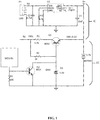
- As shown in
FIG. 1 , an embodiment of the present disclosure provides a low voltage battery charging control and protection circuit for an electronic cigarette. The circuit may include an external extended charging circuit EC. The external extended charging circuit may include: a first transistor Q1, which may include a first base, a first collector, and a first emitter. The first collector may be connected with a first external power source through a first resistor R1. The first base may be connected with the first external power source through a second resistor R2. The first emitter may be connected with a first charging port of the battery of the electronic cigarette. A second charging port of the battery of the electronic cigarette may be connected with the ground. The external extended charging circuit may also include a second transistor Q2, which may include a second base, a second collector, and a second emitter. The second collector may be connected with the first base. The second collector may also be connected with the ground through a voltage regulator tube D1. The second emitter may be connected with the ground. The second emitter and the second base may be connected through a third resistor R3. The second base may be connected with a microcontroller MCU. The low voltage battery charging control and protection circuit may also include a charging integrated circuit IC configured to connect with a second external power source. The charging integrated circuit IC may include a charging interface configured to connect with the first charging port of the battery of the electronic cigarette, and an input port configured to connect with a positive terminal of the second external power source. The negative terminal of the second external power source may be connected with the ground. The charging interface of the charging integrated circuit IC may be connected with the ground through a third capacitor C3. The positive terminal and the negative terminal of the second external power source may be connected through a second capacitor C2. - In some embodiments, the battery of the electronic cigarette may be a 5V battery. In some embodiments, the first external power source and the second external power source may both be 5V power sources, such as, for example,
USB 5V external power sources, or two different output ports of a same 5V external power sources. - Another objective of the present disclosure is to overcome the defects of the conventional technologies. The present disclosure provides an electronic cigarette having the disclosed low voltage battery charging control and protection circuit, and a method of charging the electronic cigarette based on the disclosed circuit.
- The present disclosure provides an electronic cigarette having a low voltage battery charging control and protection circuit.
- The electronic cigarette may include an atomizer, an E-liquid storage tank, a battery, and a control assembly. The battery may be connected with the control assembly. The control assembly may be connected with the atomizer. The E-liquid storage tank may be configured to provide the E-liquid to the atomizer. In some embodiments, an electrical core may be disposed in the interior of the battery. The control assembly may include the disclosed low voltage battery charging control and protection circuit.
- The method and principle of charging the electronic cigarette based on the circuit with the above disclosed separated external extended charging circuit EC and charging integrated circuit IC may include:
- Step 1: connecting an external extended charging circuit with a first external power source; and controlling, by the microcontroller, the external extended charging circuit to charge a battery of an electronic cigarette, wherein the first external power source charges the battery of the electronic cigarette first through a first transistor of the external extended charging circuit,
- Step 2: connecting an input port of a charging integrated circuit IC with a second external power source; and controlling, by the microcontroller, the external extended charging circuit and the charging integrated circuit to charge the battery of the electronic cigarette in parallel,
- Step 3: after the battery is charged to a predetermined voltage, controlling, by the microcontroller MCU, a second transistor of the external extended charging circuit to operate to forcefully pull down the voltage of the first transistor of the external extended charging circuit to terminate the operation of the first transistor (and hence terminate the charging of the battery by the external extended charging circuit); and controlling, by the microcontroller, the charging integrated circuit IC to charge the battery through the second external power source until the battery is fully charged or is charged to a predetermined voltage level.
- The principle of charging the battery through the external extended charging circuit may be described as following:
The input port of the charging integrated circuit IC may be connected with aUSB 5V power source, which may be configured to be in parallel with the external extended charging circuit. A typical charging circuit needs to have a voltage of 2.8V or more in order to provide normal charging. Therefore, according to the present disclosure, when the voltage of the electrical core of the battery of the electronic cigarette is below 3.6V, an emitter follower newly added in the external extended charging circuit may start to operate. The first 5V external power source (represented by "5V" shown next to "R1" inFIG. 1 ) connected with the external extended charging circuit ("EC" shown inFIG. 1 ) may be applied to the positive terminal of the electrical core through RI, Q1, to charge the electrical core. When the voltage of the electrical core is increased to 3.6V, because Q1 loses a bias voltage, the external extended charging circuit stops operating. The charging time of this period may be about 30 seconds. Thereafter, the charging integrated circuit IC may maintain normal operations to charge the battery until the battery is fully charged or is charged to a predetermined voltage level. - In some embodiments, the external extended charging circuit may start charging the battery under the control of the microcontroller MCU in two modes.
- a. when the voltage of the battery is relatively low (e.g., 2.8V, then the microcontroller MCU can operate normally), because the trickle current of the charging integrated circuit is relatively small, the microcontroller MCU may set the current transfer ratio ("CTR") pin to be in a low state. At this time, the external extended charging circuit starts the charging action.
- b. the voltage of the battery has been statically discharged to be overly low, and the microcontroller MCU does not respond. At this time, because of the pull-down resistor, the CTR pin may be in a low state, the external extended charging circuit may also perform the charging actions.
- The charging of the present disclosure can be understood as: at an initial state of charging the electronic cigarette based on the disclosed low voltage battery charging control and protection circuit, the charging integrate circuit IC may not charge the battery. The first external power source may charge the battery of the electronic cigarette first through the first transistor Q1 of the external extended charging circuit. After the battery has been charged to a predetermined voltage, the microcontroller MCU may control the second transistor Q2 of the external extended charging circuit to operate to forcefully pull down the voltage of the first transistor Q1 to terminate the operation of the first transistor (and hence to terminate the charging of the battery by the external extended charging circuit). The charging integrated circuit IC may start to charge the battery until the battery is fully charged or is charged to a predetermined voltage level.
- As shown in
FIG. 2 , an embodiment of the present disclosure provides a low voltage battery charging control and protection circuit. The circuit may include an extended charging circuit and a charging integrated circuit that are integrally configured or formed. The extended charging circuit may be configured to charge the battery at a first voltage. The charging integrated circuit may be configured to charge the battery at a second voltage. The first voltage may be lower than the second voltage. The extended charging circuit and the charging integrated circuit may be controlled by the microcontroller to alternately charge the battery based on the high or low level of the voltage of the battery until the battery is fully charged or is charged to a predetermined voltage level. - In some embodiments, when the extended charging circuit and the charging integrated circuit are integrally configured, the low voltage battery charging control and protection circuit may not structurally distinguish the extended charging circuit from the charging integrated circuit, but may merely functionally divide the extended charging circuit and the charging integrated circuit. That is, except for the microcontroller MCU, a circuit portion that charges the battery at the first voltage may be regarded as a portion of an extended charging circuit, and a circuit portion that charges the battery at the second voltage may be regarded as a portion of a charging integrated circuit.
- In some embodiments, the integrated low voltage battery charging control and protection circuit may include:
- a power source port configured to be connected with an input port of a charging integrated circuit IC. The power source port may also be connected with a microcontroller MCU through a voltage regulator module or voltage regulator tube. The microcontroller MCU may be connected with an enabling pin of the charging integrated circuit IC. The enabling pin of the charging integrated circuit IC may also be connected with the ground through a pull-down resistor RL;
- a first transistor Q1', which may include a first base, a first collector, and a first emitter. The first collector may be connected with a
first node 1. Thefirst node 1 may be connected with the power source port through a first resistor R1'. Thefirst node 1 and the first base may be connected through a second resistor R2'. The first emitter may be connected with asecond node 2. Thesecond node 2 may be connected with an output port of the charging integrated circuit IC; - a second transistor Q2', which may include a second base, a second collector, and a second emitter. The second collector may be connected with the first base. The second base may be connected with the microcontroller MCU through a third resistor R3'. The second emitter may be connected with the ground;
- a third transistor Q3', which may include a third base, a third collector, and a third emitter. The third base may be connected with a third node 3. The third node 3 may be connected with the microcontroller MCU through a fourth resistor R4'. The third node 3 may be connected with the ground through a fifth resistor R5'. The third collector may be connected with the ground. The third emitter may be connected with a
fourth node 4. Thefourth node 4 may be connected with the power source port through a sixth resistor R6'. - a fourth transistor Q4', which may include a fourth base, a fourth collector, and a fourth emitter. The fourth base may be connected with the
fourth node 4. The fourth collector may be connected with thesecond node 2. The fourth emitter may be connected with afifth node 5. Thefifth node 5 may be connected with asixth node 6 through a seventh resistor R7'. Thesixth node 6 may be connected with the microcontroller MCU. Thesixth node 6 may be connected with the ground through an eighth resistor R8'; and - a battery interface including a positive terminal connected with the fifth node, and a negative terminal connected with the ground. The battery interface is briefly described. It may be understood as a place for assembling the electrical core, or may be a converting interface of the electrical core, or may be a direct connector for the electrical core.
- In some embodiments, the first transistor Q1', the second transistor Q2', and the fourth transistor Q4' may all be NPN types, and the third transistor Q3' may be a PNP type.
- In some embodiments, the microcontroller MCU may be connected with the seventh node 7. The seventh node 7 may be connected with the enabling pin of the charging integrated circuit IC. The seventh node 7 may be connected with the ground through a pull down resistor.
- In some embodiments, the first base and the second collector may be connected with the
eighth node 8. Thefirst node 1 and the eightnode 8 may be connected through the second resistor R2'. - The present disclosure provides an electronic cigarette having a low voltage battery charging control and protection circuit.
- The electronic cigarette may include an atomizer, an E-liquid storage tank, a battery, and a control assembly. The battery may be connected with the control assembly. The control assembly may be connected with the atomizer. The E-liquid storage tank may be configured to provide the E-liquid to the atomizer. In some embodiments, an electrical core may be provided in the interior of the battery. The control assembly may include the disclosed low voltage battery charging control and protection circuit.
- The method and principle of charging the electronic cigarette based on the disclosed circuit may include:
- Step 1: providing an electrical power to initialize a microcontroller MCU of a low voltage battery charging control and protection circuit;
- Step 2: detecting, through the microcontroller MCU, a voltage at a positive terminal of an electrical core of a battery and controlling the charging of the electrical core of the battery based on the detected voltage,
if the detected voltage of the electrical core of the battery is lower than 2.5V, controlling, by the microcontroller, the extended charging circuit to charge the electrical core of the battery with an external power source through the first transistor Q1' and the fourth transistor Q4' of the extended charging circuit,
if the detected voltage of the electrical core of the battery is at least 3.3V, controlling, by the microcontroller, the charging integrated circuit IC to charge the electrical core of the battery with the external power source. - In some embodiments, providing the electrical power to initialize the microcontroller MCU of the low voltage battery charging control and protection circuit may be realized as follows:
The electrical core may be placed at the battery interface. First, a power source may be connected through aUSB 5V interface. At this moment, the microcontroller MCU may be reset. Each of the third transistor Q3' and the second transistor Q2' may become conductive (e.g., be in a connected state in the circuit). Specifically, the microcontroller MCU may output a low voltage to the base of the third transistor Q3' through the fourth resistor R4' and the third node 3. The third transistor Q3' may become conductive, thereby further pulling down the voltage of thefourth node 4 to be 0 V or to be substantially 0V. It does not necessarily to reduce the voltage to be 0, as long as the voltage is reduced to a level that is sufficiently low to disconnect, switch off, or disable the fourth transistor Q4'. The microcontroller MCU may output a high voltage to the base of the second transistor Q2'. The second transistor Q2' may become conductive, thereby pulling down the voltage of theeighth node 8 to be 0V or to be substantially 0V. The first transistor may become disconnected or switched off. The positive terminal of the battery interface may be connected with thefifth node 5. Thefifth node 5 may not have a voltage or a current. Thus, the battery may be in a charging-blocked state. The enabling pin EN of the charging integrated circuit IC may be at a high enabling state. The high enabling state may be understood as, when there is a high voltage signal, the charging integrated circuit IC may start, and charging is enabled; when there is no high voltage signal, the charging integrated circuit IC may not operate, and may be in a waiting state. At this moment, there is no high-enabling signal provided by the microcontroller MCU. That is, the seventh node 7 may be stably set to be in a low state through the pull-down resistor RL. At this moment, the charging integrated circuit IC may be in a non-charging state. Thus, the battery may be in a non-charging state. The dry cell symbol inFIG. 2 represents the electrical core. - In some embodiments, detecting, through the microcontroller MCU, a voltage at a positive terminal of the electrical core of the battery and charging the electrical core of the battery may be realized as follows: after the electrical power is provided to microcontroller MCU to initialize the microcontroller MCU, the microcontroller MCU may detect a voltage at the
fifth node 5 through the seventh resistor R7'. At this moment, the voltage at thefifth node 5 may be equal to the voltage at the positive terminal of the electrical core. If the detected voltage of the electrical core is lower than 2.5V, because no high voltage signal is provided to the enabling pin EN of the charging integrated circuit IC, the enabling pin EN of the charging integrated circuit IC may be set to be in a low state by the pull-down resistor RL. The microcontroller MCU may output a high voltage through the fourth resistor R4', to disconnect the third transistor R3'. The voltage at thefourth node 4 may increase, and the fourth transistor Q4' may become connected. A low voltage may be output through the fourth resistor R4', and the second transistor Q2' may be disconnected. The voltage at theeighth node 8 may increase. The first transistor Q1' may become conductive. At this moment, the power source may charge the electrical core through the first transistor Q1' and the fourth transistor Q4'. When the microcontroller MCU detects that the voltage of the electrical core is at least 3.3V, the microcontroller MCU may set the enabling pin EN of the charging integrated circuit IC to be high. At this moment, the charging integrated circuit IC may be in an enabled state, and may output a high voltage through the fourth resistor R4'. The third transistor Q3' may be disconnected. The fourth transistor Q4' may become conductive. A high voltage may be output through the third resistor R3'. The second transistor Q2' may become conductive. The first transistor Q1' may become disconnected. At this moment, the power source may output a voltage and/or a current through an output port OUT of the charging integrated circuit IC, which may pass through thesecond node 2, the fourth transistor Q4', to arrive at thefifth node 5 to charge the electrical core. - In some embodiments, the microcontroller of the low voltage battery charging control and protection circuit may be configured to automatically record a number of charging times after a low voltage discharge, calculate an accumulated total number of charging times (i.e., counts), and store the accumulated total number of charging times. When the accumulated total number of charging times after the low voltage discharge exceeds a predetermined number, the microcontroller may shut down the low voltage battery charging control and protection circuit to ensure that the battery is no longer charged and used.
- The method of charging the electronic cigarette based on the disclosed circuit may also include protecting the battery based on a number of the low voltage charging times. The protection also includes disabling the charging and hence the use of the battery after the number of the low voltage charging times has exceeded a predetermined value.
- Specifically, in some embodiments, the microcontroller MCU may automatically record a number of the low voltage charging times after a low voltage discharge and may store an accumulated total number of the low voltage charging times. The low voltage discharge is briefly described as follows. When the electrical core has a voltage lower than a predetermined voltage, the electrical core needs to be protected from further use, and should not be operated to continue to output the electrical energy. However, at this moment, if the user forcefully starts the electrical core to release the remaining electrical energy, such a use the electrical core is regarded as a low voltage discharge, which is an abnormal or unintended use. Such low voltage discharge, which is an abnormal use, should be avoided as much as possible, because it may shorten the lifetime of the electrical core.
- Using the method of charging the electronic cigarette with integrated extended charging circuit EC and the charging integrated circuit IC as an example, when the external power source is connected to provide charging, and when the electrical core is charged at a voltage lower than a predetermined voltage and when the accumulated total number of charging times of the low voltage charging has reached a predetermined number, e.g., 10 times, then when charging at the 11th time, after the microcontroller MCU is provided with the electrical power, the enabling pin EN of the charging integrated circuit may be set to be low, i.e., to be in a non-enabling state. In the meantime, a high voltage may be output through the third resistor R3' to connect the second transistor Q2', and to disconnect or switch off the first transistor Q1' synchronously. A low voltage may be output through the fourth resistor R4 to make the third transistor Q3' conductive and to synchronously disconnect or switch off the fourth transistor Q4', such that the circuit is in a shutdown state, ensuring that the battery can no longer be charged and used. The example accumulated total number of charging times, 10 times, is merely one example. The accumulated total number of charging times may be set as N, where N is a positive integer.
- By charging protection through calculating an accumulated total number of low voltage charging times and storing the accumulated total number, the electrical core can be protected by effectively ensuring that the electrical core cannot be charged and used after the electrical core has been overly discharged at a low voltage for a predetermined number of times.
- Through shutting down the charging integrated circuit IC, the first transistor Q1', and the fourth transistor Q4', the electrical core can be effectively ensured to be in a non-charging state, avoiding the occurrence of an accident. Such an overly discharged electrical core will no longer be charged, and will not be used.
- The above descriptions merely describe some embodiments of the present disclosure, and are not intended to limit the present disclosure. Any modification, equivalent substitution, and improvement made within the spirit and principle of the present disclosure all fall within the scope of protection of the present disclosure.
Claims (15)
- A low voltage charging control and protection circuit for an electronic cigarette, comprising:an extended charging circuit (EC), configured to charge a battery of the electronic cigarette at a first voltage;a charging integrated circuit (IC), configured to charge the battery of the electronic cigarette at a second voltage, wherein the first voltage is lower than the second voltage; anda microcontroller (MCU), configured to control the extended charging circuit (EC), and the charging integrated circuit (IC), to alternately charge the battery of the electronic cigarette based on a high or low level of a voltage of the battery.
- The low voltage charging control and protection circuit of claim 1,
wherein the microcontroller (MCU), is configured to:record a number of charging times after a low voltage discharge, calculate an accumulated total number of charging times, and store the accumulated total number of charging times; anddisable charging of the battery by the extended charging circuit (EC), and the charging integrated circuit (IC), when the accumulated total number of charging times after the low voltage discharge exceeds a predetermined number. - The low voltage charging control and protection circuit of claim 1 or 2,
wherein the extended charging circuit (EC), and the charging integrated circuit (IC), are independently and separately configured, with the extended charging circuit (EC), being disposed external to the charging integrated circuit (IC), and so called external extended charging circuit,
wherein the external extended charging circuit includes:a first transistor (Ql) including a first base, a first collector, and a first emitter, wherein the first collector is connected with a first external power source through a first resistor (R1), the first base is connected with the first external power source through a second resistor (R2), the first emitter is connected with a first charging port of the battery, and a second charging port of the battery is connected with a ground; anda second transistor (Q2) including a second base, a second collector, and a second emitter, wherein the second collector is connected with the first base, the second collector is also connected with the ground through a voltage regulator tube, the second emitter is connected with the ground, the second emitter and the second base are connected through a third resistor (R3), and the second base is connected with the microcontroller (MCU),wherein a charging interface of the charging integrated circuit (IC), is connected with the first charging port of the battery, an input port of the charging integrated circuit (IC), is connected with a positive terminal of a second external power source, a negative terminal of the second external power source is connected with the ground, and the charging interface of the charging integrated circuit is connected with the ground through a third capacitor (C3), and
wherein the positive terminal and the negative terminal of the second external power source are connected through a second capacitor (C2). - The low voltage charging control and protection circuit of any one of claims 1 to 3, wherein the battery of the electronic cigarette is a 5V battery, and the first external power source and the second external power source are both 5V power sources, preferably USB 5V external power sources.
- The low voltage charging control and protection circuit of claim 1 or 2,
wherein the extended charging circuit (EC), and the charging integrated circuit (IC), are structurally integrally configured; and
wherein in functions, except for the microcontroller (MCU), a circuit portion configured to charge the battery of the electronic cigarette at the first voltage is a portion of the extended charging circuit (EC), and a circuit portion configured to charge the battery of the electronic cigarette at the second voltage is a portion of the charging integrated circuit (IC). - The low voltage charging control and protection circuit of claim 5, further comprising:a power source port configured to connect with an input port of the charging integrated circuit (IC), and connect with the microcontroller (MCU), through a voltage regulator module, wherein the microcontroller (MCU), is connected with an enabling pin of the charging integrated circuit (IC), and the enabling pin of the charging integrated circuit (IC), is connected with the ground through a pull-down resistor (RL);a first transistor (Q1') including a first base, a first collector, and a first emitter, wherein the first collector is connected with a first node (1), the first node (1) is connected with the power source port through a first resistor (R1'), the first node (1) and the first base are connected through a second resistor (R2'), the first emitter is connected with a second node (2), and the second node (2) is connected with an output port of the charging integrated circuit (IC);a second transistor (Q2') including a second base, a second collector, and a second emitter, wherein the second collector is connected with the first base, the second base is connected with the microcontroller (MCU) through a third resistor (R3'), and the second emitter is connected with the ground;a third transistor (Q3') including a third base, a third collector, and a third emitter, wherein the third base is connected with a third node (3), the third node (3) is connected with the microcontroller through a fourth resistor, the third node (3) is also connected with the ground through a fifth resistor (R4'), the third collector is connected with the ground, the third emitter is connected with a fourth node (4), and the fourth node (4) is connected with the power source port through a sixth resistor (R6');a fourth transistor (Q4') including a fourth base, a fourth collector, and a fourth emitter, the fourth base is connected with the fourth node (4), the fourth collector is connected with the second node (2), the fourth emitter is connected with a fifth node (5), the fifth node (5) is connected with a sixth node (6) through a seventh resistor (R7'), the sixth node (6) is connected with the microcontroller (MCU), and the sixth node (6) is connected with the ground through an eighth resistor (R8'); anda battery interface including a positive terminal connected with the fifth node (5), and a negative terminal connected with the ground.
- The low voltage charging control and protection circuit of claim 6, wherein the first transistor (Q1'), the second transistor (Q2'), and the fourth transistor (Q4') are all NPN types, and the third transistor (Q3') is a PNP type.
- An electronic cigarette, comprising:an atomizer;an E-liquid storage tank;a battery; anda control assembly,wherein the battery is connected with the control assembly, the control assembly is connected with the atomizer, and the E-liquid storage tank is configured to provide an E-liquid to the atomizer,wherein the control assembly includes the low voltage charging control and protection circuit according to any one of claims 1-7.
- A method for charging a battery of an electronic cigarette, comprising:controlling, by a microcontroller (MCU), an extended charging circuit (EC) to charge the battery at a first voltage through a first external power source;controlling, by the microcontroller (MCU), a charging integrated circuit (IC) to charge the battery, in parallel with the extended charging circuit (EC), at a second voltage through a second external power source; andafter the battery has been charged to a predetermined voltage, controlling, by the microcontroller (MCU), the extended charging circuit (EC) to terminate charging of the battery through the first external power source, and controlling, by the microcontroller (MCU), the charging integrated circuit (IC) to charge the battery through the second external power source.
- The method of claim 9, further comprising:recording, by the microcontroller (MCU), a number of charging times after a low voltage discharge;calculating, by the microcontroller (MCU), an accumulated total number of the charging times after a low voltage discharge;storing, by the microcontroller (MCU), the accumulated total number of the charging times after a low voltage discharge; andcontrolling, by the microcontroller (MCU), to terminate the charging by the extended charging circuit (EC) and by the charging integrated circuit (IC) after the accumulated total number of charging times after a low voltage discharge has reached a predetermined number, preferably, said predetermined number is 10.
- The method of claim 9 or 10, further comprising:
detecting, by the microcontroller (MCU), the voltage of the battery. - The method of claim 11, further comprising:
controlling, by the microcontroller (MCU), the extended charging circuit (EC) and the charging integrated circuit (IC) to alternately charge the battery based on the detected voltage of the battery. - The method of any one of claims 9 to 11, wherein the method further comprises:when a voltage of the battery is below than the predetermined voltage, controlling, by the microcontroller, the extended charging circuit to charge the battery through the first external power source, andwhen the voltage of the battery reaches the predetermined voltage, controlling, by the microcontroller, the extended charging circuit to terminate charging of the battery by the extended charging circuit, and controlling, by the microcontroller, the charging integrated circuit to charge the battery through the second external power source.
- The method of claim 13, wherein controlling the extended charging circuit and the charging integrated circuit to alternately charge the battery based on the detected voltage of the battery comprises:controlling, by the microcontroller, the extended charging circuit to charge the battery when the detected voltage of the battery is lower than 2.5V; andcontrolling, by the microcontroller, the charging integrated circuit to charge the battery when the detected voltage of the battery is at least 3.3V.
- The method of any one of claims 9 to 13, wherein the predetermined voltage is 3.6V or 3.3 V.
Applications Claiming Priority (2)
| Application Number | Priority Date | Filing Date | Title |
|---|---|---|---|
| CN201821980470.9U CN209016759U (en) | 2018-11-28 | 2018-11-28 | Low pressure charging control circuit |
| CN201921513463.2U CN210380315U (en) | 2019-09-11 | 2019-09-11 | Low-voltage battery charging protection circuit |
Publications (1)
| Publication Number | Publication Date |
|---|---|
| EP3661007A1 true EP3661007A1 (en) | 2020-06-03 |
Family
ID=68731749
Family Applications (1)
| Application Number | Title | Priority Date | Filing Date |
|---|---|---|---|
| EP19211973.3A Pending EP3661007A1 (en) | 2018-11-28 | 2019-11-28 | Low voltage charging control and protection circuit for electronic cigarette and method of charging the electronic cigarette using the circuit |
Country Status (2)
| Country | Link |
|---|---|
| US (2) | US11342764B2 (en) |
| EP (1) | EP3661007A1 (en) |
Families Citing this family (5)
| Publication number | Priority date | Publication date | Assignee | Title |
|---|---|---|---|---|
| US8200496B2 (en) * | 2008-12-29 | 2012-06-12 | Motorola Mobility, Inc. | Audio signal decoder and method for producing a scaled reconstructed audio signal |
| US11342764B2 (en) * | 2018-11-28 | 2022-05-24 | Shenzhen Innokin Technology Co., Ltd. | Low voltage charging control and protection circuit for electronic cigarette and method of charging the electronic cigarette using the circuit |
| JP6865879B1 (en) * | 2020-09-07 | 2021-04-28 | 日本たばこ産業株式会社 | Aerosol generation system, aspirator controller, and power supply |
| CN113966881A (en) * | 2021-09-08 | 2022-01-25 | 深圳麦时科技有限公司 | Aerosol generating device, control method, and computer-readable storage medium |
| CN114914992B (en) * | 2022-06-14 | 2023-09-19 | 无锡力芯微电子股份有限公司 | A high-voltage dead battery pull-down module |
Citations (10)
| Publication number | Priority date | Publication date | Assignee | Title |
|---|---|---|---|---|
| US6552514B2 (en) * | 2001-08-09 | 2003-04-22 | Tai-Her Yang | Charging device including a multiple-stage voltage source for providing automatic control of charging current |
| CN204376494U (en) * | 2015-02-12 | 2015-06-03 | 湖南中烟工业有限责任公司 | A kind of electronic cigarette charging control protection electric circuit |
| CN105304962A (en) * | 2014-07-31 | 2016-02-03 | 惠州市吉瑞科技有限公司 | Electronic cigarette and charging method thereof |
| EP2985854A1 (en) * | 2013-04-11 | 2016-02-17 | Sony Corporation | Battery device |
| US20160064962A1 (en) * | 2014-09-03 | 2016-03-03 | Mophie, Inc. | Systems and methods for battery charging and management |
| EP3007306A1 (en) * | 2013-06-05 | 2016-04-13 | Kimree Hi-Tech Inc. | Electronic cigarette charging method and electronic cigarette case |
| US20160301228A1 (en) * | 2015-04-07 | 2016-10-13 | Samsung Electronics Co., Ltd. | Apparatus and method for managing power supplied to an electronic device |
| US20170303597A1 (en) * | 2015-01-26 | 2017-10-26 | Xmart Chip Microelectronic Co. Limited | Electronic Smoking Apparatus and Circuitry |
| US20180269697A1 (en) * | 2016-10-12 | 2018-09-20 | Guangdong Oppo Mobile Telecommunications Corp., Ltd. | Chargeable device and charging method |
| CN209016759U (en) * | 2018-11-28 | 2019-06-21 | 深圳市新宜康科技股份有限公司 | Low pressure charging control circuit |
Family Cites Families (11)
| Publication number | Priority date | Publication date | Assignee | Title |
|---|---|---|---|---|
| CN102282739B (en) * | 2009-01-14 | 2014-05-07 | 三美电机株式会社 | Protection monitoring circuit, battery pack, secondary battery monitoring circuit, and protection circuit |
| CA2797975C (en) * | 2010-04-30 | 2017-06-06 | Blec, Llc | Electronic smoking device |
| CN102940313B (en) * | 2012-11-13 | 2015-04-01 | 卓尔悦(常州)电子科技有限公司 | Intelligent controller and intelligent control method for electronic cigarette |
| CN203387219U (en) * | 2013-05-28 | 2014-01-08 | 向智勇 | Electronic cigarette high-efficiency charging device |
| CN104242372B (en) * | 2013-06-05 | 2018-05-22 | 惠州市吉瑞科技有限公司 | The charging method and electronic cigarette packet of electronic cigarette |
| CN105706331B (en) * | 2013-08-15 | 2019-10-15 | 富特姆4有限公司 | Method, system and apparatus for switchless detection and charging |
| CN104055224B (en) * | 2014-06-09 | 2017-01-11 | 矽力杰半导体技术(杭州)有限公司 | Integrated circuit for electronic cigarette and electronic cigarette |
| GB2559281B (en) * | 2014-07-29 | 2019-05-15 | Nicoventures Holdings Ltd | E-cigarette and re-charging pack |
| US9968137B2 (en) * | 2014-07-31 | 2018-05-15 | Zhiyong Xiang | Electronic cigarette and charging method therefor |
| CN106410897B (en) * | 2016-10-12 | 2019-02-15 | 常州市派腾电子技术服务有限公司 | Electronic cigarette and its power supply structure |
| US11342764B2 (en) * | 2018-11-28 | 2022-05-24 | Shenzhen Innokin Technology Co., Ltd. | Low voltage charging control and protection circuit for electronic cigarette and method of charging the electronic cigarette using the circuit |
-
2019
- 2019-11-27 US US16/697,360 patent/US11342764B2/en active Active
- 2019-11-28 EP EP19211973.3A patent/EP3661007A1/en active Pending
-
2022
- 2022-05-02 US US17/734,810 patent/US11923708B2/en active Active
Patent Citations (10)
| Publication number | Priority date | Publication date | Assignee | Title |
|---|---|---|---|---|
| US6552514B2 (en) * | 2001-08-09 | 2003-04-22 | Tai-Her Yang | Charging device including a multiple-stage voltage source for providing automatic control of charging current |
| EP2985854A1 (en) * | 2013-04-11 | 2016-02-17 | Sony Corporation | Battery device |
| EP3007306A1 (en) * | 2013-06-05 | 2016-04-13 | Kimree Hi-Tech Inc. | Electronic cigarette charging method and electronic cigarette case |
| CN105304962A (en) * | 2014-07-31 | 2016-02-03 | 惠州市吉瑞科技有限公司 | Electronic cigarette and charging method thereof |
| US20160064962A1 (en) * | 2014-09-03 | 2016-03-03 | Mophie, Inc. | Systems and methods for battery charging and management |
| US20170303597A1 (en) * | 2015-01-26 | 2017-10-26 | Xmart Chip Microelectronic Co. Limited | Electronic Smoking Apparatus and Circuitry |
| CN204376494U (en) * | 2015-02-12 | 2015-06-03 | 湖南中烟工业有限责任公司 | A kind of electronic cigarette charging control protection electric circuit |
| US20160301228A1 (en) * | 2015-04-07 | 2016-10-13 | Samsung Electronics Co., Ltd. | Apparatus and method for managing power supplied to an electronic device |
| US20180269697A1 (en) * | 2016-10-12 | 2018-09-20 | Guangdong Oppo Mobile Telecommunications Corp., Ltd. | Chargeable device and charging method |
| CN209016759U (en) * | 2018-11-28 | 2019-06-21 | 深圳市新宜康科技股份有限公司 | Low pressure charging control circuit |
Also Published As
| Publication number | Publication date |
|---|---|
| US11923708B2 (en) | 2024-03-05 |
| US20220263327A1 (en) | 2022-08-18 |
| US11342764B2 (en) | 2022-05-24 |
| US20200169099A1 (en) | 2020-05-28 |
Similar Documents
| Publication | Publication Date | Title |
|---|---|---|
| US11923708B2 (en) | Low voltage charging control and protection circuit for electronic cigarette and method of charging the electronic cigarette using the circuit | |
| EP3145043B1 (en) | Explosion-proof circuit, charging circuit and charging/discharging protection circuit of battery | |
| CN203481802U (en) | Battery protective circuit and system | |
| CN203722290U (en) | Battery protection module with function automatically enabling the entry of low-power consumption state and wake-up function | |
| CN106786967B (en) | Battery management device and battery charging system with same | |
| CN110829585A (en) | Two-way power supply device and power supply system | |
| CN202014087U (en) | Lithium battery charging protection circuit for portable system | |
| CN209184282U (en) | A kind of charge protector and electronic product | |
| CN210957904U (en) | Double-circuit power supply device and power supply system | |
| CN203933057U (en) | A kind of portable multi-function portable power source | |
| CN214068770U (en) | Automatic activation circuit for battery | |
| WO2023184067A1 (en) | Power supply circuit, battery management system, battery pack and electronic apparatus | |
| CN114285128A (en) | Outdoor equipment power supply control circuit, outdoor equipment power supply system and outdoor equipment | |
| CN203859538U (en) | Charging protection circuit and bluetooth loudspeaker box | |
| CN107769277B (en) | Constant-current control charging system and method | |
| CN211089223U (en) | Vehicle navigation MCU power supply circuit capable of improving power-on stability | |
| CN210380315U (en) | Low-voltage battery charging protection circuit | |
| CN212543422U (en) | Lithium battery output control circuit and multi-string lithium battery protection board | |
| CN208062858U (en) | A kind of electric power management circuit for hand-held equipment | |
| CN219247509U (en) | A wake-up circuit applied to BMS | |
| CN209151164U (en) | A kind of bluetooth equipment | |
| CN220399955U (en) | Electronic label | |
| CN223553054U (en) | Charger circuit and charger | |
| CN221862431U (en) | A BMS anti-spark circuit | |
| CN220822644U (en) | Single lithium battery charging management circuit |
Legal Events
| Date | Code | Title | Description |
|---|---|---|---|
| PUAI | Public reference made under article 153(3) epc to a published international application that has entered the european phase |
Free format text: ORIGINAL CODE: 0009012 |
|
| STAA | Information on the status of an ep patent application or granted ep patent |
Free format text: STATUS: THE APPLICATION HAS BEEN PUBLISHED |
|
| AK | Designated contracting states |
Kind code of ref document: A1 Designated state(s): AL AT BE BG CH CY CZ DE DK EE ES FI FR GB GR HR HU IE IS IT LI LT LU LV MC MK MT NL NO PL PT RO RS SE SI SK SM TR |
|
| AX | Request for extension of the european patent |
Extension state: BA ME |
|
| STAA | Information on the status of an ep patent application or granted ep patent |
Free format text: STATUS: REQUEST FOR EXAMINATION WAS MADE |
|
| 17P | Request for examination filed |
Effective date: 20201201 |
|
| RBV | Designated contracting states (corrected) |
Designated state(s): AL AT BE BG CH CY CZ DE DK EE ES FI FR GB GR HR HU IE IS IT LI LT LU LV MC MK MT NL NO PL PT RO RS SE SI SK SM TR |
|
| STAA | Information on the status of an ep patent application or granted ep patent |
Free format text: STATUS: EXAMINATION IS IN PROGRESS |
|
| 17Q | First examination report despatched |
Effective date: 20211116 |