EP3660797A1 - Auxiliary battery and auxiliary battery rental device - Google Patents
Auxiliary battery and auxiliary battery rental device Download PDFInfo
- Publication number
- EP3660797A1 EP3660797A1 EP18839396.1A EP18839396A EP3660797A1 EP 3660797 A1 EP3660797 A1 EP 3660797A1 EP 18839396 A EP18839396 A EP 18839396A EP 3660797 A1 EP3660797 A1 EP 3660797A1
- Authority
- EP
- European Patent Office
- Prior art keywords
- battery
- queue
- auxiliary
- rental
- loaded
- Prior art date
- Legal status (The legal status is an assumption and is not a legal conclusion. Google has not performed a legal analysis and makes no representation as to the accuracy of the status listed.)
- Withdrawn
Links
- 238000012546 transfer Methods 0.000 claims description 2
- 238000007599 discharging Methods 0.000 abstract description 5
- 230000007246 mechanism Effects 0.000 description 24
- 238000000034 method Methods 0.000 description 12
- 230000008569 process Effects 0.000 description 11
- 230000006870 function Effects 0.000 description 5
- 230000006835 compression Effects 0.000 description 3
- 238000007906 compression Methods 0.000 description 3
- 230000004044 response Effects 0.000 description 3
- 230000009471 action Effects 0.000 description 2
- 230000002950 deficient Effects 0.000 description 2
- 238000013459 approach Methods 0.000 description 1
- 230000001174 ascending effect Effects 0.000 description 1
- 230000006399 behavior Effects 0.000 description 1
- 235000013361 beverage Nutrition 0.000 description 1
- 230000005540 biological transmission Effects 0.000 description 1
- 239000000969 carrier Substances 0.000 description 1
- 230000000694 effects Effects 0.000 description 1
- 230000005674 electromagnetic induction Effects 0.000 description 1
- 230000006872 improvement Effects 0.000 description 1
- 238000003780 insertion Methods 0.000 description 1
- 230000037431 insertion Effects 0.000 description 1
- 238000007689 inspection Methods 0.000 description 1
- 238000012423 maintenance Methods 0.000 description 1
- 238000012986 modification Methods 0.000 description 1
- 230000004048 modification Effects 0.000 description 1
- 230000008439 repair process Effects 0.000 description 1
- 230000035939 shock Effects 0.000 description 1
Images


Classifications
-
- G—PHYSICS
- G07—CHECKING-DEVICES
- G07F—COIN-FREED OR LIKE APPARATUS
- G07F15/00—Coin-freed apparatus with meter-controlled dispensing of liquid, gas or electricity
- G07F15/003—Coin-freed apparatus with meter-controlled dispensing of liquid, gas or electricity for electricity
- G07F15/006—Coin-freed apparatus with meter-controlled dispensing of liquid, gas or electricity for electricity dispensed for the electrical charging of other devices than vehicles
-
- G—PHYSICS
- G06—COMPUTING; CALCULATING OR COUNTING
- G06Q—INFORMATION AND COMMUNICATION TECHNOLOGY [ICT] SPECIALLY ADAPTED FOR ADMINISTRATIVE, COMMERCIAL, FINANCIAL, MANAGERIAL OR SUPERVISORY PURPOSES; SYSTEMS OR METHODS SPECIALLY ADAPTED FOR ADMINISTRATIVE, COMMERCIAL, FINANCIAL, MANAGERIAL OR SUPERVISORY PURPOSES, NOT OTHERWISE PROVIDED FOR
- G06Q30/00—Commerce
- G06Q30/06—Buying, selling or leasing transactions
- G06Q30/0645—Rental transactions; Leasing transactions
-
- G—PHYSICS
- G07—CHECKING-DEVICES
- G07F—COIN-FREED OR LIKE APPARATUS
- G07F17/00—Coin-freed apparatus for hiring articles; Coin-freed facilities or services
- G07F17/0042—Coin-freed apparatus for hiring articles; Coin-freed facilities or services for hiring of objects
-
- B—PERFORMING OPERATIONS; TRANSPORTING
- B65—CONVEYING; PACKING; STORING; HANDLING THIN OR FILAMENTARY MATERIAL
- B65G—TRANSPORT OR STORAGE DEVICES, e.g. CONVEYORS FOR LOADING OR TIPPING, SHOP CONVEYOR SYSTEMS OR PNEUMATIC TUBE CONVEYORS
- B65G1/00—Storing articles, individually or in orderly arrangement, in warehouses or magazines
- B65G1/02—Storage devices
- B65G1/04—Storage devices mechanical
- B65G1/06—Storage devices mechanical with means for presenting articles for removal at predetermined position or level
-
- B—PERFORMING OPERATIONS; TRANSPORTING
- B65—CONVEYING; PACKING; STORING; HANDLING THIN OR FILAMENTARY MATERIAL
- B65G—TRANSPORT OR STORAGE DEVICES, e.g. CONVEYORS FOR LOADING OR TIPPING, SHOP CONVEYOR SYSTEMS OR PNEUMATIC TUBE CONVEYORS
- B65G60/00—Simultaneously or alternatively stacking and de-stacking of articles
-
- G—PHYSICS
- G05—CONTROLLING; REGULATING
- G05B—CONTROL OR REGULATING SYSTEMS IN GENERAL; FUNCTIONAL ELEMENTS OF SUCH SYSTEMS; MONITORING OR TESTING ARRANGEMENTS FOR SUCH SYSTEMS OR ELEMENTS
- G05B15/00—Systems controlled by a computer
- G05B15/02—Systems controlled by a computer electric
-
- G—PHYSICS
- G06—COMPUTING; CALCULATING OR COUNTING
- G06Q—INFORMATION AND COMMUNICATION TECHNOLOGY [ICT] SPECIALLY ADAPTED FOR ADMINISTRATIVE, COMMERCIAL, FINANCIAL, MANAGERIAL OR SUPERVISORY PURPOSES; SYSTEMS OR METHODS SPECIALLY ADAPTED FOR ADMINISTRATIVE, COMMERCIAL, FINANCIAL, MANAGERIAL OR SUPERVISORY PURPOSES, NOT OTHERWISE PROVIDED FOR
- G06Q10/00—Administration; Management
- G06Q10/08—Logistics, e.g. warehousing, loading or distribution; Inventory or stock management
- G06Q10/087—Inventory or stock management, e.g. order filling, procurement or balancing against orders
-
- G—PHYSICS
- G06—COMPUTING; CALCULATING OR COUNTING
- G06Q—INFORMATION AND COMMUNICATION TECHNOLOGY [ICT] SPECIALLY ADAPTED FOR ADMINISTRATIVE, COMMERCIAL, FINANCIAL, MANAGERIAL OR SUPERVISORY PURPOSES; SYSTEMS OR METHODS SPECIALLY ADAPTED FOR ADMINISTRATIVE, COMMERCIAL, FINANCIAL, MANAGERIAL OR SUPERVISORY PURPOSES, NOT OTHERWISE PROVIDED FOR
- G06Q10/00—Administration; Management
- G06Q10/10—Office automation; Time management
-
- G—PHYSICS
- G06—COMPUTING; CALCULATING OR COUNTING
- G06Q—INFORMATION AND COMMUNICATION TECHNOLOGY [ICT] SPECIALLY ADAPTED FOR ADMINISTRATIVE, COMMERCIAL, FINANCIAL, MANAGERIAL OR SUPERVISORY PURPOSES; SYSTEMS OR METHODS SPECIALLY ADAPTED FOR ADMINISTRATIVE, COMMERCIAL, FINANCIAL, MANAGERIAL OR SUPERVISORY PURPOSES, NOT OTHERWISE PROVIDED FOR
- G06Q20/00—Payment architectures, schemes or protocols
- G06Q20/08—Payment architectures
- G06Q20/18—Payment architectures involving self-service terminals [SST], vending machines, kiosks or multimedia terminals
-
- G—PHYSICS
- G07—CHECKING-DEVICES
- G07F—COIN-FREED OR LIKE APPARATUS
- G07F11/00—Coin-freed apparatus for dispensing, or the like, discrete articles
- G07F11/005—Special arrangements for insuring that only one single article may be dispensed at a time
-
- G—PHYSICS
- G07—CHECKING-DEVICES
- G07F—COIN-FREED OR LIKE APPARATUS
- G07F11/00—Coin-freed apparatus for dispensing, or the like, discrete articles
- G07F11/02—Coin-freed apparatus for dispensing, or the like, discrete articles from non-movable magazines
- G07F11/04—Coin-freed apparatus for dispensing, or the like, discrete articles from non-movable magazines in which magazines the articles are stored one vertically above the other
- G07F11/10—Coin-freed apparatus for dispensing, or the like, discrete articles from non-movable magazines in which magazines the articles are stored one vertically above the other two or more magazines having a common delivery chute
-
- G—PHYSICS
- G07—CHECKING-DEVICES
- G07F—COIN-FREED OR LIKE APPARATUS
- G07F11/00—Coin-freed apparatus for dispensing, or the like, discrete articles
- G07F11/02—Coin-freed apparatus for dispensing, or the like, discrete articles from non-movable magazines
- G07F11/04—Coin-freed apparatus for dispensing, or the like, discrete articles from non-movable magazines in which magazines the articles are stored one vertically above the other
- G07F11/14—Coin-freed apparatus for dispensing, or the like, discrete articles from non-movable magazines in which magazines the articles are stored one vertically above the other with means for raising the stack of articles to permit delivery of the topmost
-
- G—PHYSICS
- G07—CHECKING-DEVICES
- G07F—COIN-FREED OR LIKE APPARATUS
- G07F11/00—Coin-freed apparatus for dispensing, or the like, discrete articles
- G07F11/02—Coin-freed apparatus for dispensing, or the like, discrete articles from non-movable magazines
- G07F11/04—Coin-freed apparatus for dispensing, or the like, discrete articles from non-movable magazines in which magazines the articles are stored one vertically above the other
- G07F11/16—Delivery means
- G07F11/165—Delivery means using xyz-picker or multi-dimensional article picking arrangements
-
- G—PHYSICS
- G07—CHECKING-DEVICES
- G07F—COIN-FREED OR LIKE APPARATUS
- G07F17/00—Coin-freed apparatus for hiring articles; Coin-freed facilities or services
-
- G—PHYSICS
- G07—CHECKING-DEVICES
- G07F—COIN-FREED OR LIKE APPARATUS
- G07F7/00—Mechanisms actuated by objects other than coins to free or to actuate vending, hiring, coin or paper currency dispensing or refunding apparatus
- G07F7/06—Mechanisms actuated by objects other than coins to free or to actuate vending, hiring, coin or paper currency dispensing or refunding apparatus by returnable containers, i.e. reverse vending systems in which a user is rewarded for returning a container that serves as a token of value, e.g. bottles
-
- H—ELECTRICITY
- H01—ELECTRIC ELEMENTS
- H01M—PROCESSES OR MEANS, e.g. BATTERIES, FOR THE DIRECT CONVERSION OF CHEMICAL ENERGY INTO ELECTRICAL ENERGY
- H01M10/00—Secondary cells; Manufacture thereof
- H01M10/42—Methods or arrangements for servicing or maintenance of secondary cells or secondary half-cells
- H01M10/46—Accumulators structurally combined with charging apparatus
-
- H—ELECTRICITY
- H01—ELECTRIC ELEMENTS
- H01M—PROCESSES OR MEANS, e.g. BATTERIES, FOR THE DIRECT CONVERSION OF CHEMICAL ENERGY INTO ELECTRICAL ENERGY
- H01M50/00—Constructional details or processes of manufacture of the non-active parts of electrochemical cells other than fuel cells, e.g. hybrid cells
- H01M50/50—Current conducting connections for cells or batteries
-
- H—ELECTRICITY
- H02—GENERATION; CONVERSION OR DISTRIBUTION OF ELECTRIC POWER
- H02J—CIRCUIT ARRANGEMENTS OR SYSTEMS FOR SUPPLYING OR DISTRIBUTING ELECTRIC POWER; SYSTEMS FOR STORING ELECTRIC ENERGY
- H02J7/00—Circuit arrangements for charging or depolarising batteries or for supplying loads from batteries
- H02J7/0013—Circuit arrangements for charging or depolarising batteries or for supplying loads from batteries acting upon several batteries simultaneously or sequentially
-
- H—ELECTRICITY
- H02—GENERATION; CONVERSION OR DISTRIBUTION OF ELECTRIC POWER
- H02J—CIRCUIT ARRANGEMENTS OR SYSTEMS FOR SUPPLYING OR DISTRIBUTING ELECTRIC POWER; SYSTEMS FOR STORING ELECTRIC ENERGY
- H02J7/00—Circuit arrangements for charging or depolarising batteries or for supplying loads from batteries
- H02J7/0042—Circuit arrangements for charging or depolarising batteries or for supplying loads from batteries characterised by the mechanical construction
- H02J7/0045—Circuit arrangements for charging or depolarising batteries or for supplying loads from batteries characterised by the mechanical construction concerning the insertion or the connection of the batteries
-
- B—PERFORMING OPERATIONS; TRANSPORTING
- B65—CONVEYING; PACKING; STORING; HANDLING THIN OR FILAMENTARY MATERIAL
- B65G—TRANSPORT OR STORAGE DEVICES, e.g. CONVEYORS FOR LOADING OR TIPPING, SHOP CONVEYOR SYSTEMS OR PNEUMATIC TUBE CONVEYORS
- B65G57/00—Stacking of articles
- B65G57/02—Stacking of articles by adding to the top of the stack
- B65G57/03—Stacking of articles by adding to the top of the stack from above
- B65G57/06—Gates for releasing articles
-
- B—PERFORMING OPERATIONS; TRANSPORTING
- B65—CONVEYING; PACKING; STORING; HANDLING THIN OR FILAMENTARY MATERIAL
- B65G—TRANSPORT OR STORAGE DEVICES, e.g. CONVEYORS FOR LOADING OR TIPPING, SHOP CONVEYOR SYSTEMS OR PNEUMATIC TUBE CONVEYORS
- B65G59/00—De-stacking of articles
- B65G59/06—De-stacking from the bottom of the stack
- B65G59/061—De-stacking from the bottom of the stack articles being separated substantially along the axis of the stack
- B65G59/062—De-stacking from the bottom of the stack articles being separated substantially along the axis of the stack by means of reciprocating or oscillating escapement-like mechanisms
- B65G59/063—De-stacking from the bottom of the stack articles being separated substantially along the axis of the stack by means of reciprocating or oscillating escapement-like mechanisms comprising lifting means
-
- B—PERFORMING OPERATIONS; TRANSPORTING
- B65—CONVEYING; PACKING; STORING; HANDLING THIN OR FILAMENTARY MATERIAL
- B65G—TRANSPORT OR STORAGE DEVICES, e.g. CONVEYORS FOR LOADING OR TIPPING, SHOP CONVEYOR SYSTEMS OR PNEUMATIC TUBE CONVEYORS
- B65G59/00—De-stacking of articles
- B65G59/06—De-stacking from the bottom of the stack
- B65G59/067—De-stacking from the bottom of the stack articles being separated substantially perpendicularly to the axis of the stack
-
- H—ELECTRICITY
- H01—ELECTRIC ELEMENTS
- H01M—PROCESSES OR MEANS, e.g. BATTERIES, FOR THE DIRECT CONVERSION OF CHEMICAL ENERGY INTO ELECTRICAL ENERGY
- H01M2220/00—Batteries for particular applications
- H01M2220/30—Batteries in portable systems, e.g. mobile phone, laptop
Definitions
- the present invention relates to an auxiliary battery suitable for portable electronic devices such as mobile phones, and a rental device therefor.
- auxiliary battery connected to the smart phone by using a connector cable such as a USB cable.
- the auxiliary battery is required to be charged in advance and to be carried separately in addition to the smart phone.
- patent document 1 Korean Patent Publication No. 10-1684937 discloses an auxiliary battery automatic lending equipment that automatically borrows and receives auxiliary batteries. Some subway stations are equipped with the auxiliary battery automatic lending equipment. Accordingly, a person who needs a battery may rent an auxiliary battery by operating the lending equipment, and return the used battery to the lending equipment of the same system, thereby relieving the inconvenience of personally recharging and carrying the auxiliary battery.
- auxiliary battery automatic lending equipment disclosed in patent document 1, when the auxiliary battery is rented, an auxiliary battery and a connector cable selected by a user are dropped to an outlet to allow the user to take out, and when the auxiliary battery and the connector cable are returned to a return port by the user upon returning, the battery is inspected (determined whether the battery is defective or the like), and dropped and stored in the collection box. Accordingly, even when an impact absorbing member is provided, an impact may be exerted on the battery, and the battery may be damaged.
- the conventional automatic auxiliary battery rental machine merely changes a battery as a subject for rental (sale), and thus, for example, operates with substantially the same structure and manner as vending machines for canned beverages or the like. Accordingly, the management personnel is inevitable. In addition, there are many tasks to be performed by the user while paying attention during rental process.
- auxiliary battery rented from the conventional rental machine is a conventional auxiliary battery
- a real user may need a connector cable to connect the auxiliary battery to a portable electronic device of the user. Accordingly, the rental machine may lend a separate connector cable together with the battery. However, this may cause problems such as losing the connector cable or returning only the auxiliary battery while forgetting to return the connector cable.
- An object of the present invention is to provide an auxiliary battery rental device that circularly and automatically performs lending, returning, charging, and lending auxiliary batteries.
- an object of the present invention is to provide an auxiliary battery having a body and a connector cable integrated with each other to be optimized for automatic rental and return.
- an auxiliary battery rental device includes: a housing having a battery port for discharging an auxiliary battery for rental and returning the auxiliary battery after use; a rental queue vertically stacked and loaded with auxiliary batteries for rental and configured to discharge the loaded auxiliary batteries one by one according to a rental request of a user; a return queue configured to vertically receive the auxiliary batteries returned by the user one by one so as to stack and load the auxiliary batteries; a charging unit for charging the auxiliary batteries loaded in the return queue or in the return queue and the rental queue; a carrier configured to discharge the auxiliary battery discharged from the rental queue to the battery port according to the rental request of the user, and load an auxiliary battery returned through the battery port by the user onto the return queue; a lift configured to move and load the auxiliary battery loaded in the return queue to the rental queue when the rental queue is empty, when the return queue is full, or when the charging of the auxiliary battery loaded in the return queue is completed; and a control unit configured to move and load the auxiliary battery loaded in the return queue to the rental queue when
- the auxiliary batteries may be configured to be rented on a first-in and first-out basis, in which the carrier operates such an auxiliary battery loaded first among the auxiliary batteries loaded on the rental queue is discharged first, and the lift operates to move the auxiliary battery loaded on the return queue to the rental queue, such that an auxiliary battery returned and loaded on the return queue is disposed at a position to be discharged first from the rental queue.
- the battery port may be a single battery port
- the carrier may be installed to have a vertical height fixed at a same height as the battery port
- the rental queue and the return queue are disposed to vertically face each other with the carrier interposed therebetween.
- the carrier may discharge an auxiliary battery closest to the carrier among the auxiliary batteries loaded on the rental queue to the battery port, and upon the return operation, the carrier may load an auxiliary battery returned to the battery port onto a position closest to the carrier from the return queue.
- the lift may move the auxiliary battery loaded in the return queue to the rental queue by moving up and down the auxiliary battery through the carrier, in which the auxiliary battery located farthest from the carrier among the auxiliary batteries loaded in the return queue is moved to be loaded at a position closest to the carrier in the rental queue.
- the auxiliary battery rental device may include a plurality of pairs of the rental queue and the return queue vertically arranged opposite to each other in the left and right directions when viewed from a front side of the auxiliary battery rental device.
- the carrier may be configured to slide left and right after gripping both side surfaces of the auxiliary battery when viewed from the front side of the auxiliary battery rental device.
- the carrier may be configured to push out the gripped auxiliary battery toward the front side of the rental device through the battery port or pull and grip the auxiliary battery returned to the battery port.
- each of the rental queue and return queue may include a queue frame configured to limit a loading space of the auxiliary batteries, and a support member provided at the bottom of the queue frame to hold up and support the auxiliary battery loaded at the bottom, wherein the support member may be configured to selectively implement a state of supporting the auxiliary battery loaded at the bottom and a state of releasing the supporting.
- the auxiliary battery rental device may include: a housing having a battery port for discharging an auxiliary battery for rental and returning the auxiliary battery after use; a battery queue vertically stacked and loaded with auxiliary batteries for rental or returned batteries and configured to discharge the loaded batteries one by one from one end of the battery queue according to a rental request of the user, and receive the auxiliary batteries returned by the user one by one so as to load the auxiliary batteries onto the other end thereof; a charging unit configured to charge the auxiliary battery loaded in the battery queue; a carrier configured to discharge the auxiliary battery discharged from the battery queue to the battery port according to the rental request of the user, and load an auxiliary battery returned through the battery port by the user onto the battery queue; a lift configured to, upon the rental operation, move up and down the loaded auxiliary batteries such that the auxiliary battery loaded at the one end among the auxiliary batteries loaded in the battery queue is disposed at a dischargeable position, and upon the return operation, move up and down the loaded auxiliary batteries such that the returned
- the battery port may be a single battery port
- the carrier may be installed to have a vertical height fixed at a same height as the battery port
- the lift may be configured to, upon the rental operation, move the loaded auxiliary batteries such that the one end of the lift is positioned with the same height as a height of the carrier, and upon the return operation, move up and down the loaded auxiliary batteries such that the opposite end is positioned at a same height as the height of the carrier.
- the battery port may include a discharge port formed at a height corresponding to the one end of the battery queue, and a return port formed at a height corresponding to the opposite end of the battery queue.
- the carrier may include a rental carrier installed to have a fixed vertical height at a same as a height of the discharge port, and a return carrier installed to have a fixed vertical height at a same as a height of the return port.
- the lift may be configured to, upon the rental operation, move the loaded auxiliary batteries such that the one end of the loaded auxiliary battery is positioned with the same height as a height of the rental carrier, and upon the return operation, move up and down the loaded auxiliary batteries such that the opposite end of the loaded auxiliary battery is positioned with the same height as a height of the return carrier.
- the battery queue may include a queue frame configured to limit a loading space of the auxiliary batteries, and a support member provided at a lower end of the queue frame to hold up and support an auxiliary battery loaded at a bottom of the queue frame, wherein the support member may selectively implement a state of supporting the auxiliary battery loaded at the bottom and a state of releasing the supporting, and the lift may be disposed below the support member.
- the auxiliary battery when viewed from a front of the auxiliary battery rental device, may be provided in at least a rear side surface thereof with a pair of charging terminals for charging.
- the charging unit may be provided with a plurality of pairs of charging pins to come into contact with the pair of charging terminals, respectively, at a rear side of the battery queue (the rental queue and/or the return queue), so that the batteries loaded in the battery queue may be chargeable in a contact mode.
- the charging unit may be configured to allow the plurality of pairs of charging pins to be spaced apart from the charging terminals of the auxiliary battery during operation of the lift.
- the auxiliary battery may include: a case; a battery cell accommodated inside the case; and a connector electrically connected to the battery cell and connectable to a power connector of the electronic device, wherein the connector is configured to be seated in a seating groove formed at one side of the case so as to be elastically ejected, and the connector is configured to allow a connector pin connected to the power connector of the electronic device to be directed to an inside of the case. Accordingly, when the connector is seated in the seating groove, the connector pin is prevented from being exposed to an outside of the case.
- the auxiliary battery may further include an auxiliary connector disposed at the other side of the case and having a specification the same as or different from that of the connector.
- the auxiliary connector may be configured to be seated in an auxiliary seating groove formed at the other side of the case so as to be elastically ejected, and configured to allow a connector pin connected to the power connector of the electronic device to be directed to an inside of the case. Accordingly, when the auxiliary connector is seated in the auxiliary seating groove, the connector pin may be prevented from being exposed to an outside of the case.
- a pair of charging terminals for charging may be provided at one side of the case of the auxiliary battery.
- a pair of charging terminals symmetrically different from the pair of charging terminals may be further formed on the other side opposite to the one side of the case.
- auxiliary battery rental device of the present invention lending, returning, charging, and lending auxiliary batteries can be circularly and automatically performed. Accordingly, the administrative burden of the rental device can be remarkably reduced and the utilization efficiency of the device can be maximized.
- the auxiliary battery is prevented from falling when the auxiliary battery is rented and returned, so that the auxiliary battery can be prevented from being damaged upon rental or return.
- the auxiliary battery according to the present invention has a connector cable integrated with a battery body, so that additional rent and return of a connector cable is unnecessary when the auxiliary battery is rented and returned.
- the auxiliary battery can be automatically charged by the rental device, so that the auxiliary battery can be suitably used for a device that cyclically lend, receive, charge, and lend auxiliary batteries.
- reference numerals are basically assigned as numbers, but English alphabets (such as A, B, L, or R) may be added after the numbers. This is because elements are required to be illustrated or described by adding the English alphabet when it is necessary to separately describe the elements although the same numbers with English alphabets basically represent the same or corresponding elements. However, when the separate description is unnecessary, the elements are illustrated or described without adding English alphabets. In this case, the element without English alphabets includes all the elements added by English alphabets.
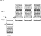
- FIG. 1 is a perspective view illustrating an external appearance of an auxiliary battery rental device according to one embodiment of the present invention.
- FIGS. 2 and 3 are perspective views from front and rear sides of the rental device after omitting a housing of the rental device, respectively.
- a rental device 100 is a device installed in a public place to lend and receive an auxiliary battery (hereinafter, simply referred to as "battery").
- the rental device of the embodiment includes a housing 101 installed therein with components.
- the housing 101 is formed with a battery port 102 serving as an outlet for a rental battery and an inlet for returning a used battery, and is provided at a suitable height thereof with an operation panel 104 formed of a touch screen or the like.
- the housing 101 is formed with a coin or bill insertion hole 103, and although not shown, may be formed with a coin return port.
- a door or housing fastening/separating structure that is opened and closed using a lock-key may be provided for maintenance and repair.
- the rental device 100 mainly includes: a frame 105 on which components constituting the rental device are installed; a battery queue 110 on which batteries 10 are vertically stacked and loaded; a carrier 120 configured to eject and discharge the batteries 10 from the battery queue 110 when the battery is rented, or load returned batteries 10 to the battery queue 110; a lift 130 configured to move up and down the batteries 10 loaded in the battery queue 110 when the batteries are rented or returned; a charging unit 140 configured to charge the batteries 10 loaded in the battery queue 110 (see FIG. 13 ); and a control unit (not shown) configured to control operations of the elements and provide an interface with a user.
- the auxiliary battery 10 rented from and returned to the rental device according to an embodiment of the present invention has a certain specification (such as size, capacity, or connector structure), and although not particularly limited, may have an approximately rectangular parallelepiped shape that may be stacked and loaded in a thickness direction (vertical direction) of the battery queue 110. Meanwhile, the auxiliary battery used in the present embodiment has a structure that may be particularly suitable for the rental device according to an embodiment of the present invention, and will be described later in detail.
- the battery queue 110 includes a pair of a rental queue 110A that loads the batteries 10 for rental and discharge the batteries one by one according to a rental request of the user, and a return queue 110B that receive and load return batteries one by one.
- the rental queue 110A and the return queue 110B are disposed to vertically face each other while a carrier 120 is interposed therebetween.
- the rental queue 110A is disposed above the carrier 120
- the return queue 110B is disposed below the carrier 120.
- the upper or lower position of the rental queue 110A and the return queue 110B may be changed.
- FIGS. 2 and 3 shows that two pairs of the rental queue 110A and the return queue 110B are disposed in left and right directions.
- Batteries loaded in the left pair and the right pair may have the same specification, or the batteries having different specifications may be loaded (for example, batteries for Android-based smart phones on the left pair, and batteries for iPhone on the right pair).
- the present invention as shown in FIGS. 2 and 3 , is not limited to the two pairs of battery queues, and three pairs or more may be provided or only one pair may be provided.
- the battery queue 110 may be implemented as a queue frame 111 that defines a space in which the batteries 10 are mounted to be movable up and down.
- the battery queue 110 has a support member for supporting a battery 10 loaded at the bottom thereof.
- the rental queue 110A has a claw-shaped support member 112 disposed at a lower end of the queue frame 111A to support the batteries by embracing both edges of a bottom surface of the battery 10 loaded at the bottom.
- the support member 112 of the rental queue 110A may implement a state in which the support member is closed in the left and right directions to support the battery 10 (the state of FIG. 4 ), by a driving mechanism such as a motor 113 (see FIG.
- the support member 112 of the rental queue 110A when viewed from the front side, has a sharp wedge-shape toward the battery 10 to slightly lift the battery 10 by the thickness thereof when the support member 112 is closed after opened in the left and right directions.
- the support member 112 of the rental queue 110A is called a queue nail, and detailed operations will be described later.
- the return queue 110B has a plate-shaped support member 131.
- the plate-shaped support member 131 has a structure that always supports the bottom loaded battery, unlike the queue nail 112 of the rental queue 110A that may implement a support state and a release state of the battery. Meanwhile, the support member 131 of the return queue 110B constitutes a part of the lift 130 to be described later.
- FIG. 5 is a perspective view excerpting and illustrating only a frame 105, a carrier 120, and a carrier sliding mechanism in the rental device according to the present embodiment.
- FIG. 6 is a perspective illustrating the carrier 120. The carrier 120 and the sliding mechanism thereof will be described with reference to FIGS. 5 and 6 .
- the carrier 120 is a component configured to eject the battery 10 from the rental queue 110A and discharge the ejected battery to the battery port 102 (see FIG. 1 ), or receive the battery 10 returned through the battery port 102 and load the battery on the return queue 110B.
- the carrier 120 has a fixed vertical height equal to a height of the battery port 102, and is installed to be slid in the left and right directions.
- the carrier 120 is formed at a center thereof with a storage space 121 in which the battery 10 is gripped and stored or through which the battery vertically passes.
- a driving mechanism is provided at left and right sides of the storage space 121 to grip the battery 10 or allow the battery 10 to be discharged toward and introduce from a front of the rental device.
- the driving mechanism includes a roller 122 provided on both side walls of the storage space 121 and a motor (not shown) for rotating the roller to discharge the battery 10 to the battery port 102, or to receive the battery 10, which is returned to the battery port 102, into the storage space 121 when the storage space 121 is aligned with the battery port 102 (see FIG. 1 ).
- the motor may rotate forward and backward to enable both discharging (rental) and introducing (return) of the battery, and the direction of rotation may be determined according to the user input on the operation panel 104 (see FIG. 1 ), or by a sensor (not shown) provided near the storage space 121 by detecting whether the battery is discharged or introduced.
- the roller 122 has been described as a driving mechanism for discharging and introducing the battery 10
- the embodiment may be implemented by a scheme other than the rollers, for example, by a push rod that pushes the battery 10 forward from a rear of the storage space 121.
- the introducing (the return) of the battery 10 may be implemented by allowing a user to push the battery manually.
- the driving mechanism includes a gripping member for gripping the battery.
- the gripping member includes four carrier nails 123 capable of moving back and forth with respect to the storage space near four corners of the storage space 121, links 124, and a motor (not shown). Left two of the four carrier nails 123 operate same with each other, right two operate same with each other in which the left carrier nails operate symmetrically with the right carrier nails. More specifically, each of the carrier nails 123, as shown in FIG. 7 , includes a pair of upper carrier nails 123AL and 123AR and lower carrier nails 123BL and 123BR, and is connected to a rotating shaft 125, which is connected to the motor, through upper links 124AL and 124AR and lower links 124BL and 124BR, respectively.
- the upper and lower carrier nails 123A and 123B move forward and backward toward the battery present in the storage space 121 by rotation of the motor via the links 124A and 124B therebetween, so that the battery can be gripped and released.
- the upper carrier nail 123A and the upper link 124A may be configured to interwork with the lower carrier nail 123B and the lower link 124B
- the upper carrier nail 123A and the upper link 124A may be configured to operate independently of each other. This is because the carrier nail 123 is allowed not only to function to grip the battery 10 but also to move up and down the battery 10 by about one space unit upward or downward from the storage space 121 in cooperation with the above-described queue nail 112 (detailed operations will be described later).
- the sliding mechanism for sliding the carrier 120 in the left and right directions includes: motors 126 provided on both lower sides of the frame 105; a wire 128 wound or released in accordance with rotation of the motor to pull a movable pulley 127; the movable pulley 127 pulled by the wire 128 to move up and down; and a sliding wire 129 having one end fixed to the frame 105 and the other end wound around the movable pulley 127 by a half turn and then connected to the carrier 120.
- the motor 126 on the right side is rotated to wind the wire 128 on the right side and lower the movable pulley 127 on the right side, so that the sliding wire 129 on the right pulls the carrier 120 in the right direction.
- the wire 128 on the left side, the movable pulley 127 on the left side, and the sliding wire 129 on the left side the wire 128 is naturally released according to an operation of the sliding mechanism on the right side, the movable pulley 127 moves up, and the sliding wire 129 moves in the right direction.
- the motor 126 on the left side is simultaneously rotated, if necessary, so that the sliding mechanism on the left side may operate in conjunction with the sliding mechanism on the right side.
- the carrier sliding mechanism in the rental device of the present embodiment may be implemented in other way such as caterpillar-type chain, belt, or wire, and may be implemented by a linear motor or a hydraulic/pneumatic cylinder.
- the sliding wire 129 may be implemented as a chain or belt instead of the wire.
- the rental device of the embodiment employs the plurality of pairs of rental queues 110A and return queues 110B and is configured to have only one battery port 102
- the carrier 120 for moving the battery between the battery queue 110 and the battery port 102 is required to have a slid structure in the left and right directions.
- the battery port 102 may be formed between the rental queue 110A and the return queue 110B, and the carrier 120 may be fixedly disposed at a position where the storage space 121 is aligned with the battery port 102. Accordingly, the sliding mechanism for sliding the carrier 120 in the left and right directions is unnecessary.
- FIGS. 7 to 12 are front views illustrating operations of the carrier and the battery support member.
- FIGS. 7 to 12 shows operations in which the battery 10 located in the storage space 121 of the carrier is raised by one space and loaded at a bottom of the rental queue 110A above the carrier 120, with interwork (cooperation) between the queue nail 112 and the carrier nail 123.
- the carrier 120 is slid in the left and right directions, so that the storage space 121 of the carrier is positioned between the rental queue 110A and the return queue 110B.
- the batteries loaded in the return queue 110B are raised by the lift 130 described later such that the battery 10 loaded on the top of the return queue 110B enters the storage space 121 of the carrier.
- the carrier nails 123 are in a state of being retracted from the storage space 121, and the queue nails 112 of the rental queue 110A are in a state of being closed and supporting the batteries 10 loaded on the rental queue 110A.
- the carrier nails 123 move toward the battery 10 located in the storage space 121 (see arrows), so that the battery is slightly raised by the thickness of the carrier nail 123 while holding both sides of the battery 10.
- the upper links 124A and the lower links 124B are rotated in the same direction about the rotating shaft 125 (see arrows), so that the battery gripped by the carrier nails 123 is raised to approach the battery 10 loaded at the bottom of the rental queue 110A.
- the queue nails 112 of the rental queue 110A are still closed, in which a gap equal to the thickness of the queue nail 112 exists between the battery 10 lifted by the carrier nails 123 and the battery 10 loaded at the bottom of the rental queue 110A.
- FIGS. 4 and 6 since positions of the queue nail 112 and the carrier nail 123 for gripping the battery 10 do not overlap each other, the grips do not interfere with each other.
- the queue nails 112 are closed (see arrows), so that the lifted battery 10 is loaded at the bottom of the rental queue 110A and supported.
- not only the gripping operation of the battery but also the lifting operation of the battery may be implemented by the queue nails 112 provided in the battery queue 110 and the carrier nails 123 provided in the carrier 120.
- the auxiliary battery rental device may automatically charge the discharged battery returned after use, and the battery may be provided for rental again.
- the configuration of the charging unit for implementing the above will be described with reference to FIGS. 13 to 15 .
- the charging unit is disposed at a rear side of the return queue 110B and the rental queue 110A. Since the batteries loaded in the return queue 110B are the batteries required to be charged, it may be sufficient to provide the charging unit only to the return queue 110B. However, in some cases (for example, in the case that the return queue is full and the return is impossible), even the battery without being completely charged needs to be moved to an empty rental queue 110A. In order to continuously charge the battery after moved to the rental queue, the charging unit also may be provided in the rental queue 110A.
- the charging unit 140 includes a circuit board 141, and pairs of charging pins 142, in which the pairs of charging pins 142 configured to come into contact with charging terminals 13 (see FIG. 49 ) of the battery, respectively are provided with as many pairs as the number of batteries that may be loaded in the battery queue 110.
- electronic components such as circuit elements electrically connected to the charging pins 142 for charging, and a microprocessor stored therein with a control program for controlling a charging process are mounted in the circuit board 141.
- the control program may be programmed to allow each of batteries to be individually and independently charged.
- the charging pin 142 may be a so-called pogo pin type charging pin as shown in FIG. 13(a) , in which a spring is accommodated therein to elastically and stably come into contact with the charging terminal of the battery.
- the charging unit 140 configured as the above description, as shown in FIG. 13(c) , is mounted to the queue frame 111 located at a rear side of the battery queue 110, in which the charging unit 140 may be mounted to be spaced apart from/accessible to the queue frame 111, and eventually, the charging terminal of the battery.
- the batteries 10 loaded on the battery queue 110 in the rental device according to an embodiment of the present invention may move up and down by the queue nails 112 and/or the carrier nails 123 as described above, or may move up and down by the lift 130 as described later.
- the charging pin 142 of the charging unit 140 is always in contact with the charging terminal 13 (see FIG.
- the battery may not easily move up and down or the charging pin 142 or the charging terminal 13 may be damaged. Accordingly, the charging unit (the charge pin) may be spaced apart from the battery (the charge terminal) while the battery 10 moving up and down.
- the charging unit 140 is mounted to the queue frame 111 via links.
- the charging unit (circuit board; 141) is rotatably connected to one movable joint 151b of a first link 151 having a fixed joint 151a fixed to the queue frame 111 and rotatable and two movable joints 151b and 151c.
- One end of a second link 152 disposed in parallel with the queue frame 111 is rotatably connected to the movable joint 151c of the first link 151, and the other end of the second link 152 is rotatably connected to a movable joint 153b of a third link 153 disposed in parallel with the first link 151.
- the third link 153 is rotatably fixed to the queue frame 111 through a fixed joint 153a, and a movable end 153c opposite to the movable joint 153b of the third link 153 is connected to a motor 155 (see FIG. 3 ) via a gear or cam mechanism.
- the motor 155 moves the movable end 153c of the third link 153 upward, the third link 153 is rotated about the fixed joint 153a, and thus the movable joint 153b and the second link 152 connected to the movable joint 153b move downward. Accordingly, since the movable joint 151c of the first link 151 moves downward, and the other movable joint 151b moves leftward and downward, the circuit board 141 connected to the movable joint 151b moves leftward, and thus the charging pins 142 are spaced apart from the charging terminals of the battery 10.
- the battery is provided with a pair of charging terminals at positions corresponding to the pair of charging pins 141 of the charging unit 140, and this will be described later in detail.
- so-called contact-type charging is performed in which charging is carried out by allowing the corresponding charging pins to come into contact with the charging terminals of the battery.
- the present invention is not limited thereto, and a contact-less charging using electromagnetic induction may also be performed.
- the lift 130 includes the plate-shaped support member 131 described with reference to FIG. 2 , and the driving mechanism for moving up and down the battery 10 mounted on the support member 131.
- the driving mechanism includes a motor 132 (see FIG. 2 ) and a gear mechanism, in which the gear mechanism may include a pinion 133 rotated by the motor 132 and a rack 134 disposed vertically along a side surface of the return queue 110B.
- the lift may be implemented by a motor and a screw, or may be implemented using a hydraulic or pneumatic cylinder.
- the operation of moving the batteries 10B loaded in the return queue 110B to the rental queue 110A may be performed as follows.
- the carrier 20 is slid left and right such that the storage space 21 of the carrier 20 is arranged between the rental queue 110A and the return queue 110B.
- both the carrier nails 123 and the queue nails 112 are opened.
- FIGS. 7 to 12 illustrate that an upper end of the return queue 110B disposed below the carrier 120 is provided with queue nails and a driving mechanism for opening and closing the queue nails.
- the drawings merely reflect that the components of the rental device may be standardized by identically configuring and symmetrically arranging the rental queue 110A and the return queue 110B with each other.
- the queue nail and the queue nail driving mechanism are not necessarily provided on the top of the return queue 110B.
- the plate-shaped support member 131 moves up in a state that the carrier 120, rental queue 110A, and the return queue 110B are aligned as above and both of the carrier nails 123 and the queue nails 112 are opened.
- the batteries 10 loaded thereon move up through the storage space 121 of the carrier 120 and the opened queue nails 112 of the rental queue 110A, and enter the rental queue 110A.
- the charging unit 140 is spaced apart from the battery toward the rear side of the battery queue 110 at least during operation of the lift 130, so that the battery may move up and down smoothly and the battery may be prevented from being damaged.
- the motor 132 of the lift 130 stops and the queue nails 112 of the rental queue 110A are closed to support the batteries, which are transferred to the rental queue 110A, from below.
- the battery at the bottom of the raised batteries may be located below the queue nails 112 of the rental queue 110A, depending on an operating range of the lift 130.
- the battery at the bottom may be raised to the rental queue 110A by the operation as described with reference to FIGS. 7 to 12 .
- the above problem may be avoided by configuring the plate-shaped support member 131 such that an upper end surface of the plate-shaped support member 131 is about the same as a height of the queue nails 112 of the rental queue 110A when the plate-shaped support member 131 ascended at the highest.
- the operation of moving the batteries 10 loaded in the return queue 110B to the rental queue 110A by using the lift 130 is performed when the rental queue 110A is empty, when the return queue 110B is full, or when the charging of the battery 10 loaded in the return queue is completed.
- the motor 132 of the lift 130 may be controlled to allow the plate-shaped support member 131 to move only up to the extent as possible.
- the carrier nails 123 and the queue nails 112 of the rental queue 110A are immediately opened to raise the batteries loaded in the return queue 110B, the battery remaining in the rental queue 110A may fall and collide with a battery loaded on the top of the return queue 110B and be damaged. Accordingly, in this case, only the carrier nails 123 may be opened while closing the queue nails 112 of the rental queue 110A and the lift 130 may be operated. When the battery loaded on the top of the return queue 110B rises just below the queue nails 112 of the rental queue 110A, the lift 130 stops. Then, the queue nails 112 of rental queue 110A may be opened and the battery remaining in the rental queue 110A may be gently disposed on the battery raised from the return queue 110B, and then the lift 130 may operate again to raise the combined batteries together up to the available height.
- the discharged and returned batteries can be immediately charged in the device and moved to the rental queue 110A, so that lending, returning, charging, and lending can be circularly and automatically performed. Accordingly, the needs to do additional work of collecting and charging the returned batteries, and replenishing charged batteries for rental are remarkably reduced.
- rental operation ( FIGS. 16 to 22 ) of the batteries in the rental device according to an embodiment of the present invention
- return operation FIGS. 23 to 26
- moving operation of the batteries from the return queue to the rental queue FIGS. 27 to 30
- FIGS. 16 to 30 and FIGS. 31 to 48 are views for explaining the operation of the rental device according to another embodiment described later.
- the queue nails 112 are shown as an L-shape in the rental queue 110A
- only the carrier nails 123 are also shown as an L shape in the carrier 120
- only the plate-shaped support member 131 is shown in the lift 130.
- FIGS. 16 to 48 for convenience of understanding and explanation, available and charged batteries are hatched, and batteries to be returned (or having been returned) are considered as discharged and are not hatched.
- FIGS. 16 to 48 show examples in which four battery queues are arranged laterally, and describe that actual operations are applied only to the leftmost battery queue, the number of battery queues is not limited to the illustrated examples, and the actual operation may be applied to the other battery queues.
- the batteries returned may be stacked in another return queue having room of the same specification.
- FIG. 16 as a standby state shows a state in which each of the four rental queues 110A is loaded with ten charged batteries 10A, and each of the four return queues 110b is loaded with one returned and discharged battery 10B.
- the carrier 120 is positioned in a state where the storage space 121 of the carrier is aligned with the battery port 102 (see FIG. 1 ), the queue nails 112 of each rental queue 110A supports the loaded batteries 10A while being closed below the battery 10A loaded at the bottom.
- the lift 130 (plate-shaped support member 131) is positioned such that the top surface of the battery 10B loaded on the top of the return queue 110B is positioned at the same height as the bottom surface of the carrier 120.
- the carrier 120 moves below the rental queue 110A (hereinafter, described as the leftmost rental queue) on which a battery to be rented of a desired specification is loaded, and opens the carrier nails 123 ( FIG. 17 ).
- the lift 130 is raised to allow the battery 10B loaded in the return queue 110B to pass through the storage space 121 between the opened carrier nails 123 and to rise below the rental queue 110A. Then, the lift 130 stops and then the queue nails 112 of the rental queue 110A are opened to gently put the batteries 10A loaded in the rental queue 110A onto the raised battery 10B ( FIG. 18 ).
- the lift 130 descends to lower the entire batteries 10A and 10B by one space, and the queue nails 112 of the rental queue 110A are closed ( FIG. 19 ). Accordingly, the battery 10K positioned directly below the closed queue nails 112 is disposed in the storage space 121 of the carrier 120. In this state, the carrier nails 123 are closed and the battery 10K disposed in the storage space 121 is gripped as an object to be rented ( FIG. 20 ).
- the roller 122 (see FIG. 6 ) of the carrier 120 is driven, the battery 10K gripped by the carrier 120 is discharged to the battery port 102, and thus the rental device becomes in a standby state again ( FIG. 22 ) (in FIG. 22 , dotted lines for the battery 10K indicate that the battery has been discharged). Accordingly, the rental operation of the battery is completed, in which nine batteries 10A after reducing one are loaded in the leftmost rental queue 110A.
- FIG. 23 shows that the roller 122 of the carrier 120 pulls the battery 10P and receives the battery in the storage space 121 of the carrier when the user pushes the battery 10P through the battery port 102 to return the battery to the carrier 120 of the rental device in the standby state (as shown in FIG. 16 ). Meanwhile, in this state, seven batteries 10A are loaded in the leftmost rental queue 110A, and one battery 10B is loaded in the return queue 110.
- the carrier 120 having received the returned battery 10P moves the battery 10P to the return queue 110B (in this example, the leftmost return queue) to load the battery ( FIG. 24 ). Then, the carrier nails 123 are opened to gently place the returned battery 10P stored in the storage space 121 onto the battery 10B loaded on the top of the return queue 110B.
- the lift 130 descends by one space to move down the batteries 10B and 10P loaded on the lift 130 such that the top surface of the just-loaded returned battery 10P is positioned at the same height as the bottom surface of the carrier 120 ( FIG. 25 ).
- the carrier 120 returns to the standby position and thus the return operation is completed, in which the leftmost return queue 110 is loaded with two batteries 10B and 10P that are added by one battery.
- the batteries 10B and 10A loaded in the return queue 110B or in the return queue and the rental queue 110A are always charged using the above-mentioned charging unit 140, except for the rental operation and return operation as described above, and the moving operation described later.
- FIG. 27 shows a typical situation where the batteries need to be moved from the return queue 110B to the rental queue 110A, in which the leftmost rental queue 110A is empty and the corresponding return queue 110B is full. Meanwhile, in this example, charging six batteries 10B returned first and begun in charging first has been completed among eleven returned batteries 10B loaded in the leftmost return queue 110B, and five batteries 10B returned and loaded later have not been charged yet.
- the first operation for moving (raising) the eleven batteries 10B loaded in the return queue 110B to the rental queue 110A is to move the carrier 120 such that the storage space 121 of the carrier 120 is aligned between the leftmost return queue 110B and the rental queue 110A.
- FIGS. 16 to 48 show the carrier 120 with only the carrier nails 123. This is because there may be the case in which the battery outside the carrier nails 123 cannot move up and down due to a carrier body or carrier sliding mechanism (see FIGS. 5 and 6 ). Accordingly, as shown in FIG.
- the carrier 20 moves between the leftmost rental queue 110A and the return queue 110B, and the carrier nails 123 and queue nails 112 of rental queue are opened to allow the batteries 10B loaded in the return queue 110B to pass through the carrier 120 and be movable up toward the rental queue 110A.
- the batteries 10B loaded in the return queue 110B are raised to the rental queue 110A using the lift 130, and the queue nails 112 are closed to support the lifted batteries 10A ( FIG. 29 ).
- the carrier 20 moves to the standby position ( FIG. 30 ), and thus the moving operation is completed.
- eleven batteries 10A are loaded in the leftmost rental queue 110A. Meanwhile, charging is resumed by the charging unit 140 in the rental queue 110A for five batteries, in which the movement is completed and the charging is incomplete.
- the batteries 10B returned to the return queue 110B is charged by the charging unit 140 except when the rental device is operating (renting, returning, and moving operations), and moved to the rental queue 110A so as to be provided to the rental, so that the auxiliary batteries can be cyclically rented.
- the battery loaded at the bottom of the return queue 110B (first of all) is moved to the bottom of the rental queue 110A when moved, and the battery loaded at the bottom of the rental queue 110A is rented when rented.
- a so-called first-in and first-out method is employed in which a battery previously returned and loaded is rented first. Accordingly, it is possible to lend a battery that is returned first and has a longer charging time (charged first), so that a waiting time can be minimized and the rental device can be operated efficiently.
- the rental device may allow the battery to be rented, returned, recharged, and rented automatically and cyclically without the management personnel.
- charged batteries to be rented may be mounted at the same time by the management personnel.
- the management personnel opens the housing 101 or a door of the rental device, the batteries is necessary to be loaded to the rental queue 110A.
- the queue frame 111A of the rental queue 110A may be opened towards a front of the device, or the rental queue 110A may be opened by opening the queue frame, which blocks the front of the device, using a door type.
- the return queue 110B may be formed with a front-opening structure or in a door mode in which the charged rental batteries are collectively mounted onto the return queue 110B, and then the above-described moving operation is performed, so that the batteries collectively mounted onto the return queue 110B may be moved to the rental queue 110A.
- the battery queue is divided into the rental queue 110A and the return queue 110B in the rental device of the above-described embodiment, but the rental device may be operated with one battery queue (a bundle of loaded batteries).
- batteries are managed by loading the batteries in a bundle, the batteries loaded in the battery queue are discharged from one end (the lowermost one) and rented one by one, the returned battery is loaded at the other end (the uppermost one).
- the configuration itself of the rental device according to the present embodiment is not different from the rental device of the above-described embodiment.
- the battery queue 110 of the rental device as shown in FIGS. 2 and 3 , the queue frame 111A constituting the rental queue 110A is installed above the carrier 120 together with the above-described queue nails 112 around the carrier 120, and a queue frame 111B constituting the return queue 110B is installed below the carrier 120 together with the above-described plate-shaped support member 131.
- the discharge and introduction of the batteries are carried out through a single battery port 102.
- the batteries are controlled to be loaded in a bundle.
- a physical battery queue formed by the queue frames 111A and 111B is divided into a rental queue and a return queue, but a conceptual battery queue as a bundle of loaded batteries is one.
- FIG. 31 as a standby state shows that each of the four rental queues 110A is loaded with ten batteries 10, in which the top three of the ten batteries are discharged (that is, returned) batteries, and the bottom seven are charged batteries.
- returned battery is loaded on the top of the return queue 110B upon return operation described later in the above-described embodiment, however, the returned batteries are sequentially loaded on top of the batteries currently loaded in the rental queue 110A as one bundle in the present embodiment (the detailed operation will be described later). Accordingly, the return queue 110B below the carrier 120 is empty.
- the above-described charging unit 140 is disposed at a rear side of the rental queue 110A and always charges the three discharged batteries except when the device is in operation.
- the carrier 120 moves below the rental queue 110A (hereinafter, described as the leftmost rental queue) on which a battery to be rented of a desired specification is loaded, opens the carrier nails 123, raises and places the lift 130 directly below the rental queue 110A, and opens the queue nails 112 of the rental queue 110A to gently put the batteries 10 loaded in the rental queue 110A onto the lift 130 (the plate-shaped support member)( FIG. 32 ).
- the rental queue 110A hereinafter, described as the leftmost rental queue
- the lift 130 descends to lower the entire batteries 10 by one space, and the queue nails 112 of the rental queue 110A are closed ( FIG. 33 ). Accordingly, the battery 10K positioned directly below the closed queue nails 112 is disposed in the storage space 121 of the carrier 120. In this state, the carrier nails 123 are closed and the battery 10K disposed in the storage space 121 is gripped as an object to be rented ( FIG. 34 ).
- the roller 122 (see FIG. 6 ) of the carrier 120 is driven, the battery 10K gripped by the carrier 120 is discharged to the battery port 102, and thus the rental device becomes in a standby state again ( FIG. 35 ). Accordingly, the rental operation of the battery is completed, in which nine batteries 10 after reducing one are loaded in the leftmost rental queue 110A.
- the rental operation in the rental device is substantially the same as in the above-described embodiment.
- the rental operation when the rental operation is performed in a state in which the return queue 110B is empty in FIG. 16 of the above-described embodiment, it becomes substantially the same as in FIG. 31 to 35 mentioned above.
- FIG. 36 as a standby state shows that the leftmost rental queue 110A is loaded with seven batteries (three are discharged batteries and four are charged batteries), and the return queue 110B is empty.
- the lift 130 moves down to allow the uppermost battery among the loaded batteries 10 to be positioned directly below the carrier 120, and the carrier 120 moves to the position of the battery port 102 ( FIG. 38 ), thereby receiving the returned battery 10P into the storage space 121 ( FIG. 39 ).
- the carrier 120 moves back to the leftmost battery queue 110 ( FIG. 40 ), and the carrier nails 123 are opened to gently place the returned battery 10P stored in the storage space 121 onto the battery 10 loaded on the top of the return queue 110B. Then, the queue nails 112 are also opened ( FIG. 41 ), and the lift 130 moves up to allow the lowermost battery among the loaded batteries to be positioned directly above the carrier 120 ( FIG.42 ).
- the carrier 120 returns to the standby position and thus the return operation is completed, in which the leftmost rental queue 110A is loaded with eight batteries 10 and 10P that are added by one battery.
- the batteries loaded in the rental queue 110A move to the return queue 110B, the returned battery 10P are loaded on top of the loaded batteries 10, and the entire batteries move to the rental queue 110A again.
- the return operation immediately starts in the above-described embodiment (see FIG. 23 ).
- the user first is required to apply for a return through the operation panel 104 before the battery is inserted ( FIG. 39 ) and the rental device is required to prepare to receive the returned battery ( FIGS. 36 to 38 ).
- the battery port 102 in the standby state is required to be closed by means such as a door in order to prevent the user from inserting and returning the battery into the battery port 102 during the standby state and the return-preparing work.
- the standby state has been defined in the above description as a state in which the batteries are disposed in the rental queue 110A (see FIGS. 31 and 36 ).
- the standby state may be defined as a state in which batteries are disposed in the return queue 110B (the batteries of all battery queues in FIG. 39 are in the return queue 110B below the carrier 120.
- the carrier 120 receives and loads the returned battery 10P onto top of the batteries 10 loaded in the return queue 110B, and thus the return may be completed.
- the battery queue is operated with a single battery queue conceptually.
- the rental queue 110A and the return queue 110B are physically provided and only half of the total loading capacity may be utilized as an actual battery loading capacity, the availability for a volume of the device is lowered.
- another embodiment described below provides a rental device having a structure that may utilize all of the loading capacity of the battery queue, although one battery queue is operated as in the present embodiment.
- the rental device is physically provided with one battery queue 110.
- the battery port is divided into a discharge port provided at a lower end of the battery queue 110 to discharge (lend) the battery, and a return port provided at an upper end of the battery queue 110 to allow the battery to be inserted (returned).
- a rental carrier 120A and a return carrier 120B are separately provided at the same heights as the battery discharge port and the battery return port, respectively, in response to the battery discharge port and the battery return port.
- the battery discharge port and the battery return port differ only in the height and the number thereof, but have the same configurations as the battery port 102 of the above-described embodiments.
- the rental carrier 120A and the return carrier 120B also differ only in the height and the number thereof, but have the same configurations as the carrier 120 of the above-described embodiments.
- the battery queue 110 of the present embodiment has a configuration obtained by adding components 131, 132, 133, and 134 of the lift provided in the return queue 110B to the rental queue 110A (including the queue frame 111A and the queue nails 112) of the above-described embodiments.
- FIG. 44 shows the standby state in the rental device according to the present embodiment for the above configuration.
- the leftmost rental queue 110 is loaded with seven batteries (three are discharged battery and four are charged battery), and the rental carrier 120A and the return carrier 120B are aligned with the battery discharge port and the battery return port, respectively.
- the rental operation in the present embodiment is the same as the rental operation in the above-described embodiment described with reference to FIGS. 31 to 35 , hereinafter, only the battery return operation of the rental device according to the present embodiment will be described.
- the roller 122 of the return carrier 120B pulls the battery 10P and receives the battery into the storage space 121 of the return carrier. Then, the rental carrier 120A is moved below the battery queue 110 (the leftmost battery queue) to load the returned battery 10P, the carrier nails 123A of the rental carrier 120A are opened, and the lift 130 is raised just below the leftmost battery queue 110. Then, the queue nails 112 of the battery queue 110 are opened to gently place the batteries 10 having been loaded in the battery queue 110 onto the lift 130.
- the lift 130 raises the batteries 10 loaded in the battery queue 110, such that the top surface of the battery 10 loaded on the top is positioned at the same height as the bottom surface of the return carrier 120B.
- the return carrier 120B that has received the returned battery 10P moves the battery 10P to the leftmost battery queue 110, and the carrier nails 123B are opened to gently place the returned battery 10P stored in the storage space 121 onto the battery 10 loaded on the top of the battery queue 110.
- the lift 130 lowers the batteries 10 and 10P loaded in the battery queue 110 so that the battery 10 loaded at the bottom is positioned directly above the rental carrier 120A, and the queue nails 112 of the battery queue 110 are closed to support the loaded batteries 10 and 10P. Then, the lift 130 returns to the initial position, the rental carrier 120A and the return carrier 120B are returned to the initial positions, and thus the return operation is completed ( FIG. 48 ). In the returned state, the leftmost battery queue 110 is loaded with eight batteries 10 and 10P that are added by one battery.
- the rental carrier 120A and the return carrier 120B have been described as being sequentially moved in the above description, the rental carrier 120A and the return carrier 120B may simultaneously move in parallel unless the rental carrier 120A and the return carrier 120B interfere with the return operation.
- one conceptual and physical battery queue 110 is used, and the rental and the return are performed using the carriers 120A and 120B and the battery ports (the discharge port and the return port), respectively. Accordingly, compared to the above-described embodiment described with reference to FIGS. 31 to 43 , a vertical moving width of the loaded batteries may be reduced, and an entire loading capacity of the battery queue 110 may be utilized as an actual battery loading capacity.
- the above embodiments have illustrated and described that the battery at the bottom of the battery queue is discharged and rented when the battery is rented, and the returned battery is loaded on the top of the battery queue (return queue).
- the battery loaded on the top of the battery queue may be rented, and the returned battery may be inserted into and loaded on the bottom of the battery queue.
- the auxiliary battery rental device 100 may be installed in a number of places, and may be centrally controlled by a server, or established as mobile power infrastructure that is controlled in a parallel or distributed way.
- the rental device 100 may be operated as a system that allows a direct rent/return on site without additional membership, may be operated as a membership system that requires a preliminary registration, or a combination thereof may be available.
- operations by the user such as membership registration and rental/return application, and user interface may be implemented by the operation panel 104 of the rental device 100, may be implemented in the form of a smart phone application, and may be implemented by interworking the operation panel and the smart phone application.
- the auxiliary battery 10 which is particularly suitable for the auxiliary battery rental device 100 of the present invention, according to another aspect of the present invention will be described.
- the conventional auxiliary battery requires a separate connector and a connector cable for connecting the battery to a portable electronic device.
- the conventional auxiliary battery rental device is configured and operated to separately lend and receive the connector cable together with the auxiliary battery.
- this causes problems such as loss or non-return of the connector cable.
- the connector is integrally accommodated into the auxiliary battery to prevent the above problem.
- FIG. 49 is a perspective view illustrating an internal configuration of the auxiliary battery according to one embodiment of the present invention.
- FIG. 50 is a perspective view illustrating a state in which the connector is ejected from the auxiliary battery of FIG. 49 .
- FIG. 51 is a perspective view illustrating a state of using the auxiliary battery.
- the auxiliary battery 10 includes a case 11 (the upper and lower cases are omitted in FIGS. 49 and 50 ), a battery cell 12 accommodated inside the case 11, and a connector 14 electrically connected to the battery cell 12 and connectable to a power connector of the electronic device. Since the case 11 and the battery cell 12 are substantially the same as those of a general auxiliary battery, the detailed description will be omitted. Hereinafter, a difference from the general auxiliary battery will be described with respect to the connector 14 that is a feature of the present invention.
- the connector 14 of the battery 10 is seated on a seating groove 11a formed at one side of the case 11 so as to be elastically ejected.
- the connector 14 is seated in the seating groove 11a, an outer surface of the connector 14 is leveled with a surface of the case 11, and a connector pin 14a (see FIG. 50 ) connected to a power connector of an electronic device is not exposed outside the case 11 (see FIG. 49 ).
- the connector 14 including the connector pin 14a is ejected together with a connector wire 15 by a predetermined length, and thus the connector pin 14a is exposed, so that the auxiliary battery 10 can be used by connecting the connector pin to the power connector of the electronic device 20 (smart phone) (see FIGS. 50 and 51 ).
- the connector 14 returns to an initial state (being seated in the seating groove 11a) by an elastic force.
- one end of a pair of connector wires 15 is fixed to a surface facing the connector seating groove 11a of the connector 14, the pair of connector wires 15 are wound to a pair of movable pulleys 16 elastically biased by springs 17, respectively, and the other end of the connector wire 15 is fixed inside the case 11.
- the spring 17 is a compression spring that elastically biases such that the movable pulley 16 is pushed away toward a deep inside of the case 11.
- the connector 14 is seated in the connector seating groove 11a, and the connector 14 is ejected with the elastic force when the connector 14 is pulled out.
- the connector 14 is automatically seated in the connector seating groove 11a by an elastic restoring force of the spring 17.
- the connector 14 since the pair of connector wires 15, the pair of movable pulleys 16 and the pair of springs 17 are used, unbalanced force or torque may be absorbed even for predetermined twisting or unbalanced pulling up, down, left and right after the connector 14 is ejected. When the force is removed, the connector 14 may be seated in the connector seating groove 11a while being automatically balanced.
- the connector wire 15 may also function as a connector cable.
- the connector wire 15 may be electrically connected to the battery cell 12 to supply power from the battery cell 12 to the connector pin 14a, and transfer an electrical signal such as a control signal between the electronic device 20 and the battery cell 12.
- the auxiliary battery 10 accommodates the connector and the connector cable, and the connector 14 is not exposed and has the same appearance as a normal auxiliary battery when not used, additional rent and return of a separate connector cable is unnecessary when used in a battery rental device such as the above-described auxiliary battery rental device 100, so that the configuration of the battery rental device can be simplified and the problems such as loss or non-return of the connector cable can be prevented.
- the auxiliary battery 10 may further include an auxiliary connector 18 in addition to the connector 14 having the above-described structure.
- the auxiliary connector 18 may have specifications the same as or different from the above-described connector 14.
- the auxiliary connector 18 may also be configured to be elastically ejected from the other side of the case 11 in the same manner as the above-described connector 14. Accordingly, in particular, when an auxiliary connector 18 having another specification is further provided in addition to the connector 14, one auxiliary battery 10 may support smart phones of different specifications, and types of smart phones are not required to be distinguished in the auxiliary battery rental device, so that the process of controlling the rental device can be simplified, and a rapid increase of demands for rental of a battery having a specific specification can be handled.
- one side of the case 11 of the auxiliary battery 10 according to an embodiment of the present invention may be provided with a pair of charging terminals 13 for charging the battery.
- the pair of charging terminals 13 come into contact with the charging pins 141 of the charging unit 140 of the rental device described with reference to FIGS. 13 to 15 , thereby allowing the battery 10 to be automatically charged while being loaded in the battery queue 110.
- another pair of charging terminals in the auxiliary battery 10 may be further provided at the other side symmetrically opposite to one side of the case provided with the above pair of charging terminals 13, in addition to the pair of charging terminals 13. Accordingly, when the auxiliary battery 10 of the present invention is returned to the above-described auxiliary battery rental device 100, the returned battery can be charged at any time by the charging unit 140 provided at the rear of the battery queue 110 regardless of whether an inserting direction of the battery 10 into the battery port 102 is a front or a rear of the battery 10.
- a tension spring installed on the opposite side of the compression spring 17 may be used, a leaf spring or a wire spring other than a coil spring may be used, and a power cord ejection/return mechanism in a vacuum cleaner or the like may be employed.
- the battery 10 may include a memory for storing a unique ID, a rental/return history, a user ID, a usage control program of the battery, and the like.
- the information stored in the memory may be used to determine whether the rented battery was misused or wrongfully used, and whether the returned battery is defective, and also may be used to statistically analyze using behaviors of users.
Abstract
Description
- The present invention relates to an auxiliary battery suitable for portable electronic devices such as mobile phones, and a rental device therefor.
- Recently, as the portable electronic devices represented by smart phones are increasingly spread rapidly, and functions thereof are diversified, more portable electronic devices are being used instead of printing media such as newspapers during movement such as commute. Although the using time of the portable electronic devices increases remarkably during the day, and the power consumption increases due to high-level function, the capacity growth rate of a battery as a power source for the portable electronic devices cannot meet the demand.
- Meanwhile, because a battery of a recent smart phone is not allowed to be attached to and detached from a smart phone body mainly because of the improvement of the waterproof function, it has become substantially impossible to charge the batteries in convenience stores or the like.
- Accordingly, many people use their smart phones while carrying an auxiliary battery connected to the smart phone by using a connector cable such as a USB cable. However, the auxiliary battery is required to be charged in advance and to be carried separately in addition to the smart phone.
- Meanwhile, patent document 1 (Korean Patent Publication No.
10-1684937 - However, above all, according to the lending equipment disclosed in
patent document 1, used batteries are returned through a return port and stored in a collection box inside the lending equipment, and then a management personnel regularly is required to visit, collect and separately charge the discharged batteries collected in the collection box. At this time, the management personnel fills the lending equipment with charged batteries for rental while collecting the discharged batteries. Accordingly, there is a limit that the management personnel is mandatory for the conventional lending equipment and the managing frequency by the management personnel increases for lending equipment installed in places having demands for the batteries. - In addition, according to the auxiliary battery automatic lending equipment disclosed in
patent document 1, when the auxiliary battery is rented, an auxiliary battery and a connector cable selected by a user are dropped to an outlet to allow the user to take out, and when the auxiliary battery and the connector cable are returned to a return port by the user upon returning, the battery is inspected (determined whether the battery is defective or the like), and dropped and stored in the collection box. Accordingly, even when an impact absorbing member is provided, an impact may be exerted on the battery, and the battery may be damaged. - Meanwhile, upon returning, for inspection of the returned auxiliary battery, there is an inconvenience that the user is necessary to connect the battery to a connector port provided in the return port through a connector cable. Since unfamiliar users skip the above connection of the connector, the battery is not properly inspected or the return process is incomplete, and thus it may be recorded as an unreturned state.
- In other words, the conventional automatic auxiliary battery rental machine merely changes a battery as a subject for rental (sale), and thus, for example, operates with substantially the same structure and manner as vending machines for canned beverages or the like. Accordingly, the management personnel is inevitable. In addition, there are many tasks to be performed by the user while paying attention during rental process.
- In addition, since the auxiliary battery rented from the conventional rental machine is a conventional auxiliary battery, a real user may need a connector cable to connect the auxiliary battery to a portable electronic device of the user. Accordingly, the rental machine may lend a separate connector cable together with the battery. However, this may cause problems such as losing the connector cable or returning only the auxiliary battery while forgetting to return the connector cable.
- The present invention is provided to solve the above conventional problems. An object of the present invention is to provide an auxiliary battery rental device that circularly and automatically performs lending, returning, charging, and lending auxiliary batteries.
- In addition, an object of the present invention is to provide an auxiliary battery having a body and a connector cable integrated with each other to be optimized for automatic rental and return.
- To achieve the above-mentioned objects, an auxiliary battery rental device according to an aspect of the present invention includes: a housing having a battery port for discharging an auxiliary battery for rental and returning the auxiliary battery after use; a rental queue vertically stacked and loaded with auxiliary batteries for rental and configured to discharge the loaded auxiliary batteries one by one according to a rental request of a user; a return queue configured to vertically receive the auxiliary batteries returned by the user one by one so as to stack and load the auxiliary batteries; a charging unit for charging the auxiliary batteries loaded in the return queue or in the return queue and the rental queue; a carrier configured to discharge the auxiliary battery discharged from the rental queue to the battery port according to the rental request of the user, and load an auxiliary battery returned through the battery port by the user onto the return queue; a lift configured to move and load the auxiliary battery loaded in the return queue to the rental queue when the rental queue is empty, when the return queue is full, or when the charging of the auxiliary battery loaded in the return queue is completed; and a control unit configured to control operations of the rental device including the carrier, the charging unit and the lift, in response to the rental request or return action of the user and a state of the auxiliary battery rental device.
- The auxiliary batteries may be configured to be rented on a first-in and first-out basis, in which the carrier operates such an auxiliary battery loaded first among the auxiliary batteries loaded on the rental queue is discharged first, and the lift operates to move the auxiliary battery loaded on the return queue to the rental queue, such that an auxiliary battery returned and loaded on the return queue is disposed at a position to be discharged first from the rental queue.
- According to one embodiment, the battery port may be a single battery port, the carrier may be installed to have a vertical height fixed at a same height as the battery port, and the rental queue and the return queue are disposed to vertically face each other with the carrier interposed therebetween. Upon the rental operation, the carrier may discharge an auxiliary battery closest to the carrier among the auxiliary batteries loaded on the rental queue to the battery port, and upon the return operation, the carrier may load an auxiliary battery returned to the battery port onto a position closest to the carrier from the return queue. When the auxiliary battery loaded on the return queue moves to the rental queue by the lift, the lift may move the auxiliary battery loaded in the return queue to the rental queue by moving up and down the auxiliary battery through the carrier, in which the auxiliary battery located farthest from the carrier among the auxiliary batteries loaded in the return queue is moved to be loaded at a position closest to the carrier in the rental queue.
- In addition, the auxiliary battery rental device may include a plurality of pairs of the rental queue and the return queue vertically arranged opposite to each other in the left and right directions when viewed from a front side of the auxiliary battery rental device. The carrier may be configured to slide left and right after gripping both side surfaces of the auxiliary battery when viewed from the front side of the auxiliary battery rental device. In addition, the carrier may be configured to push out the gripped auxiliary battery toward the front side of the rental device through the battery port or pull and grip the auxiliary battery returned to the battery port.
- In addition, each of the rental queue and return queue may include a queue frame configured to limit a loading space of the auxiliary batteries, and a support member provided at the bottom of the queue frame to hold up and support the auxiliary battery loaded at the bottom, wherein the support member may be configured to selectively implement a state of supporting the auxiliary battery loaded at the bottom and a state of releasing the supporting.
- In addition, the auxiliary battery rental device according to an embodiment of the present invention may include: a housing having a battery port for discharging an auxiliary battery for rental and returning the auxiliary battery after use; a battery queue vertically stacked and loaded with auxiliary batteries for rental or returned batteries and configured to discharge the loaded batteries one by one from one end of the battery queue according to a rental request of the user, and receive the auxiliary batteries returned by the user one by one so as to load the auxiliary batteries onto the other end thereof; a charging unit configured to charge the auxiliary battery loaded in the battery queue; a carrier configured to discharge the auxiliary battery discharged from the battery queue to the battery port according to the rental request of the user, and load an auxiliary battery returned through the battery port by the user onto the battery queue; a lift configured to, upon the rental operation, move up and down the loaded auxiliary batteries such that the auxiliary battery loaded at the one end among the auxiliary batteries loaded in the battery queue is disposed at a dischargeable position, and upon the return operation, move up and down the loaded auxiliary batteries such that the returned auxiliary battery is loaded on the opposite end; and a control unit configured to control operations of the rental device including the carrier, the charging unit and the lift, in response to the rental request or return action of the user and a state of the auxiliary battery rental device.
- The battery port may be a single battery port, the carrier may be installed to have a vertical height fixed at a same height as the battery port, and the lift may be configured to, upon the rental operation, move the loaded auxiliary batteries such that the one end of the lift is positioned with the same height as a height of the carrier, and upon the return operation, move up and down the loaded auxiliary batteries such that the opposite end is positioned at a same height as the height of the carrier.
- Alternatively, the battery port may include a discharge port formed at a height corresponding to the one end of the battery queue, and a return port formed at a height corresponding to the opposite end of the battery queue. The carrier may include a rental carrier installed to have a fixed vertical height at a same as a height of the discharge port, and a return carrier installed to have a fixed vertical height at a same as a height of the return port. The lift may be configured to, upon the rental operation, move the loaded auxiliary batteries such that the one end of the loaded auxiliary battery is positioned with the same height as a height of the rental carrier, and upon the return operation, move up and down the loaded auxiliary batteries such that the opposite end of the loaded auxiliary battery is positioned with the same height as a height of the return carrier.
- In addition, the battery queue may include a queue frame configured to limit a loading space of the auxiliary batteries, and a support member provided at a lower end of the queue frame to hold up and support an auxiliary battery loaded at a bottom of the queue frame, wherein the support member may selectively implement a state of supporting the auxiliary battery loaded at the bottom and a state of releasing the supporting, and the lift may be disposed below the support member.
- In addition, the auxiliary battery, when viewed from a front of the auxiliary battery rental device, may be provided in at least a rear side surface thereof with a pair of charging terminals for charging. The charging unit may be provided with a plurality of pairs of charging pins to come into contact with the pair of charging terminals, respectively, at a rear side of the battery queue (the rental queue and/or the return queue), so that the batteries loaded in the battery queue may be chargeable in a contact mode.
- In this case, the charging unit may be configured to allow the plurality of pairs of charging pins to be spaced apart from the charging terminals of the auxiliary battery during operation of the lift.
- In addition, the auxiliary battery according to another aspect of the invention may include: a case; a battery cell accommodated inside the case; and a connector electrically connected to the battery cell and connectable to a power connector of the electronic device, wherein the connector is configured to be seated in a seating groove formed at one side of the case so as to be elastically ejected, and the connector is configured to allow a connector pin connected to the power connector of the electronic device to be directed to an inside of the case. Accordingly, when the connector is seated in the seating groove, the connector pin is prevented from being exposed to an outside of the case.
- The auxiliary battery may further include an auxiliary connector disposed at the other side of the case and having a specification the same as or different from that of the connector.
- In this case, the auxiliary connector may be configured to be seated in an auxiliary seating groove formed at the other side of the case so as to be elastically ejected, and configured to allow a connector pin connected to the power connector of the electronic device to be directed to an inside of the case. Accordingly, when the auxiliary connector is seated in the auxiliary seating groove, the connector pin may be prevented from being exposed to an outside of the case.
- In addition, a pair of charging terminals for charging may be provided at one side of the case of the auxiliary battery.
- In this case, a pair of charging terminals symmetrically different from the pair of charging terminals may be further formed on the other side opposite to the one side of the case.
- According to the auxiliary battery rental device of the present invention, lending, returning, charging, and lending auxiliary batteries can be circularly and automatically performed. Accordingly, the administrative burden of the rental device can be remarkably reduced and the utilization efficiency of the device can be maximized.
- In addition, according to the auxiliary battery rental device of the present invention, the auxiliary battery is prevented from falling when the auxiliary battery is rented and returned, so that the auxiliary battery can be prevented from being damaged upon rental or return.
- In addition, the auxiliary battery according to the present invention has a connector cable integrated with a battery body, so that additional rent and return of a connector cable is unnecessary when the auxiliary battery is rented and returned.
- In addition, according to the auxiliary battery of the present invention, the auxiliary battery can be automatically charged by the rental device, so that the auxiliary battery can be suitably used for a device that cyclically lend, receive, charge, and lend auxiliary batteries.
- The drawings accompanying in the present specification are merely illustrate preferred embodiments according to the present invention, and serve to further understand the technical idea of the present invention together with the detailed description of the invention to be described later, so the present invention should not be construed to limit the matters described in the drawings.
-
FIG. 1 is a perspective view illustrating an external appearance of an auxiliary battery rental device (hereinafter, simply referred to as "a rental device") according to one embodiment of the present invention. -
FIG. 2 is a perspective view from a front lower side of the rental device after omitting a housing of the rental device according to an embodiment of the present invention. -
FIG. 3 is a perspective view from a rear upper side of the rental device after omitting the housing of the rental device according to one embodiment of the present invention. -
FIG. 4 is a perspective view illustrating a part of a lower end of a battery queue and a battery support member provided in the lower end of the battery queue in the rental device according to one embodiment of the present invention. -
FIG. 5 is a perspective view excerpting and illustrating only a frame, a carrier, and a carrier sliding mechanism in the rental device according to one embodiment of the present invention. -
FIG. 6 is a perspective view illustrating the carrier illustrated inFIG. 5 and an auxiliary battery. -
FIGS. 7 to 12 are front views illustrating operations of the carrier and the battery support member in the rental device according to one embodiment of the present invention. -
FIG. 13 is a perspective view illustrating a structure of a charging unit of the rental device according to an embodiment of the present invention. -
FIGS. 14 and15 are side views illustrating operations of the charging unit illustrated inFIG. 13 . -
FIGS. 16 to 22 are front views conceptually illustrating operations of an auxiliary battery rental process of the rental device according to one embodiment of the present invention. -
FIGS. 23 to 26 are front views conceptually illustrating operations of an auxiliary battery return process of the rental device according to one embodiment of the present invention. -
FIGS. 27 to 30 are front views conceptually illustrating a process of moving an auxiliary battery loaded on a return queue to a rental queue in the rental device according to one embodiment of the present invention. -
FIGS. 31 to 35 are front views conceptually illustrating operations of an auxiliary battery rental process of the rental device according to one embodiment of the present invention. -
FIGS. 36 to 43 are front views conceptually illustrating operations of an auxiliary battery return process of the rental device according to one embodiment of the present invention. -
FIGS. 44 to 48 are front views conceptually illustrating operations of an auxiliary battery return process of the rental device according to one embodiment of the present invention. -
FIG. 49 is a perspective view illustrating the auxiliary battery after omitting top and bottom cases thereof according to one embodiment of the present invention. -
FIG. 50 is a perspective view illustrating a state in which a connector is ejected from the auxiliary battery illustrated inFIG. 49 . -
FIG. 51 is a perspective view illustrating a state of use of the auxiliary battery according to one embodiment of the present invention. - Hereinafter, an auxiliary battery rental device according to exemplary embodiments of the present invention will be described in detail with reference to the accompanying drawings. Above all, the terms and words used in the specification and claims of the present invention should not be construed as limited to a conventional or lexical meaning, and should be construed as the meanings and concepts consistent with the technical idea of the present invention, based on the principle that "an inventor may define the concept of the term properly in order to describe the invention in the best way".
- In addition, the directions such as up, down, left, right, front, and rear and the terms indicating the same are shown and used for convenience of description depictions of the drawings and the following description. Accordingly, the direction may be changed depending on observing or implementing directions of the present invention.
- Meanwhile, in the drawings and the following description, reference numerals are basically assigned as numbers, but English alphabets (such as A, B, L, or R) may be added after the numbers. This is because elements are required to be illustrated or described by adding the English alphabet when it is necessary to separately describe the elements although the same numbers with English alphabets basically represent the same or corresponding elements. However, when the separate description is unnecessary, the elements are illustrated or described without adding English alphabets. In this case, the element without English alphabets includes all the elements added by English alphabets.
-
FIG. 1 is a perspective view illustrating an external appearance of an auxiliary battery rental device according to one embodiment of the present invention.FIGS. 2 and3 are perspective views from front and rear sides of the rental device after omitting a housing of the rental device, respectively. - Referring to
FIG. 1 , arental device 100 according to an embodiment of the present invention is a device installed in a public place to lend and receive an auxiliary battery (hereinafter, simply referred to as "battery"). The rental device of the embodiment includes ahousing 101 installed therein with components. Thehousing 101 is formed with abattery port 102 serving as an outlet for a rental battery and an inlet for returning a used battery, and is provided at a suitable height thereof with anoperation panel 104 formed of a touch screen or the like. In addition, thehousing 101 is formed with a coin orbill insertion hole 103, and although not shown, may be formed with a coin return port. A door or housing fastening/separating structure that is opened and closed using a lock-key may be provided for maintenance and repair. - Referring to
FIGS. 2 and3 , therental device 100 according to an embodiment of the present invention mainly includes: aframe 105 on which components constituting the rental device are installed; abattery queue 110 on whichbatteries 10 are vertically stacked and loaded; acarrier 120 configured to eject and discharge thebatteries 10 from thebattery queue 110 when the battery is rented, or load returnedbatteries 10 to thebattery queue 110; alift 130 configured to move up and down thebatteries 10 loaded in thebattery queue 110 when the batteries are rented or returned; acharging unit 140 configured to charge thebatteries 10 loaded in the battery queue 110 (seeFIG. 13 ); and a control unit (not shown) configured to control operations of the elements and provide an interface with a user. - The
auxiliary battery 10 rented from and returned to the rental device according to an embodiment of the present invention has a certain specification (such as size, capacity, or connector structure), and although not particularly limited, may have an approximately rectangular parallelepiped shape that may be stacked and loaded in a thickness direction (vertical direction) of thebattery queue 110. Meanwhile, the auxiliary battery used in the present embodiment has a structure that may be particularly suitable for the rental device according to an embodiment of the present invention, and will be described later in detail. - In the embodiment, the
battery queue 110 includes a pair of arental queue 110A that loads thebatteries 10 for rental and discharge the batteries one by one according to a rental request of the user, and areturn queue 110B that receive and load return batteries one by one. Therental queue 110A and thereturn queue 110B are disposed to vertically face each other while acarrier 120 is interposed therebetween. In other words, in the embodiment, therental queue 110A is disposed above thecarrier 120, and thereturn queue 110B is disposed below thecarrier 120. However, the upper or lower position of therental queue 110A and thereturn queue 110B may be changed. - Meanwhile,
FIGS. 2 and3 shows that two pairs of therental queue 110A and thereturn queue 110B are disposed in left and right directions. Batteries loaded in the left pair and the right pair may have the same specification, or the batteries having different specifications may be loaded (for example, batteries for Android-based smart phones on the left pair, and batteries for iPhone on the right pair). Of course, the present invention, as shown inFIGS. 2 and3 , is not limited to the two pairs of battery queues, and three pairs or more may be provided or only one pair may be provided. - The
battery queue 110 may be implemented as aqueue frame 111 that defines a space in which thebatteries 10 are mounted to be movable up and down. In addition, thebattery queue 110 has a support member for supporting abattery 10 loaded at the bottom thereof. - Specifically, the
rental queue 110A, as shown inFIG. 4 , has a claw-shapedsupport member 112 disposed at a lower end of thequeue frame 111A to support the batteries by embracing both edges of a bottom surface of thebattery 10 loaded at the bottom. Thesupport member 112 of therental queue 110A may implement a state in which the support member is closed in the left and right directions to support the battery 10 (the state ofFIG. 4 ), by a driving mechanism such as a motor 113 (seeFIG. 3 ), apower transmission mechanism rotating arm 119, when viewed from the front side, and a state in which the support member is opened in the left and right directions to release the support of the battery, and thebattery 10 passes through the lower end of therental queue 110A so as to move up and down. In addition, thesupport member 112 of therental queue 110A, when viewed from the front side, has a sharp wedge-shape toward thebattery 10 to slightly lift thebattery 10 by the thickness thereof when thesupport member 112 is closed after opened in the left and right directions. Hereinafter, thesupport member 112 of therental queue 110A is called a queue nail, and detailed operations will be described later. - Meanwhile, as shown in
FIG. 2 , thereturn queue 110B has a plate-shapedsupport member 131. The plate-shapedsupport member 131 has a structure that always supports the bottom loaded battery, unlike thequeue nail 112 of therental queue 110A that may implement a support state and a release state of the battery. Meanwhile, thesupport member 131 of thereturn queue 110B constitutes a part of thelift 130 to be described later. -
FIG. 5 is a perspective view excerpting and illustrating only aframe 105, acarrier 120, and a carrier sliding mechanism in the rental device according to the present embodiment.FIG. 6 is a perspective illustrating thecarrier 120. Thecarrier 120 and the sliding mechanism thereof will be described with reference toFIGS. 5 and6 . - The
carrier 120 is a component configured to eject thebattery 10 from therental queue 110A and discharge the ejected battery to the battery port 102 (seeFIG. 1 ), or receive thebattery 10 returned through thebattery port 102 and load the battery on thereturn queue 110B. In this embodiment, thecarrier 120 has a fixed vertical height equal to a height of thebattery port 102, and is installed to be slid in the left and right directions. - As shown in
FIG. 6 , thecarrier 120 is formed at a center thereof with astorage space 121 in which thebattery 10 is gripped and stored or through which the battery vertically passes. In addition, a driving mechanism is provided at left and right sides of thestorage space 121 to grip thebattery 10 or allow thebattery 10 to be discharged toward and introduce from a front of the rental device. - Specifically, the driving mechanism includes a
roller 122 provided on both side walls of thestorage space 121 and a motor (not shown) for rotating the roller to discharge thebattery 10 to thebattery port 102, or to receive thebattery 10, which is returned to thebattery port 102, into thestorage space 121 when thestorage space 121 is aligned with the battery port 102 (seeFIG. 1 ). The motor may rotate forward and backward to enable both discharging (rental) and introducing (return) of the battery, and the direction of rotation may be determined according to the user input on the operation panel 104 (seeFIG. 1 ), or by a sensor (not shown) provided near thestorage space 121 by detecting whether the battery is discharged or introduced. - In the embodiment, although the
roller 122 has been described as a driving mechanism for discharging and introducing thebattery 10, the embodiment may be implemented by a scheme other than the rollers, for example, by a push rod that pushes thebattery 10 forward from a rear of thestorage space 121. In this case, the introducing (the return) of thebattery 10 may be implemented by allowing a user to push the battery manually. - The driving mechanism includes a gripping member for gripping the battery. As shown in
FIG. 6 , the gripping member includes fourcarrier nails 123 capable of moving back and forth with respect to the storage space near four corners of thestorage space 121, links 124, and a motor (not shown). Left two of the fourcarrier nails 123 operate same with each other, right two operate same with each other in which the left carrier nails operate symmetrically with the right carrier nails. More specifically, each of the carrier nails 123, as shown inFIG. 7 , includes a pair of upper carrier nails 123AL and 123AR and lower carrier nails 123BL and 123BR, and is connected to arotating shaft 125, which is connected to the motor, through upper links 124AL and 124AR and lower links 124BL and 124BR, respectively. The upper andlower carrier nails storage space 121 by rotation of the motor via thelinks upper carrier nail 123A and theupper link 124A may be configured to interwork with thelower carrier nail 123B and thelower link 124B, theupper carrier nail 123A and theupper link 124A may be configured to operate independently of each other. This is because thecarrier nail 123 is allowed not only to function to grip thebattery 10 but also to move up and down thebattery 10 by about one space unit upward or downward from thestorage space 121 in cooperation with the above-described queue nail 112 (detailed operations will be described later). - The sliding mechanism for sliding the
carrier 120 in the left and right directions, as shown inFIG. 5 , includes:motors 126 provided on both lower sides of theframe 105; awire 128 wound or released in accordance with rotation of the motor to pull amovable pulley 127; themovable pulley 127 pulled by thewire 128 to move up and down; and a slidingwire 129 having one end fixed to theframe 105 and the other end wound around themovable pulley 127 by a half turn and then connected to thecarrier 120. Accordingly, in order to slide thecarrier 120 in a right direction for example, themotor 126 on the right side is rotated to wind thewire 128 on the right side and lower themovable pulley 127 on the right side, so that the slidingwire 129 on the right pulls thecarrier 120 in the right direction. At this time, with regard to thewire 128 on the left side, themovable pulley 127 on the left side, and the slidingwire 129 on the left side, thewire 128 is naturally released according to an operation of the sliding mechanism on the right side, themovable pulley 127 moves up, and the slidingwire 129 moves in the right direction. Alternatively, themotor 126 on the left side is simultaneously rotated, if necessary, so that the sliding mechanism on the left side may operate in conjunction with the sliding mechanism on the right side. - Meanwhile, the carrier sliding mechanism in the rental device of the present embodiment may be implemented in other way such as caterpillar-type chain, belt, or wire, and may be implemented by a linear motor or a hydraulic/pneumatic cylinder. In addition, in the above embodiment, the sliding
wire 129 may be implemented as a chain or belt instead of the wire. - Further, since the rental device of the embodiment employs the plurality of pairs of
rental queues 110A and returnqueues 110B and is configured to have only onebattery port 102, thecarrier 120 for moving the battery between thebattery queue 110 and thebattery port 102 is required to have a slid structure in the left and right directions. However, when only one pair ofrental queue 110A andreturn queue 110B is employed, thebattery port 102 may be formed between therental queue 110A and thereturn queue 110B, and thecarrier 120 may be fixedly disposed at a position where thestorage space 121 is aligned with thebattery port 102. Accordingly, the sliding mechanism for sliding thecarrier 120 in the left and right directions is unnecessary. - Then, operational examples of the
queue nail 112 and thecarrier nail 123 will be described with reference toFIGS. 7 to 12 that are front views illustrating operations of the carrier and the battery support member. - The operational examples illustrated in
FIGS. 7 to 12 shows operations in which thebattery 10 located in thestorage space 121 of the carrier is raised by one space and loaded at a bottom of therental queue 110A above thecarrier 120, with interwork (cooperation) between thequeue nail 112 and thecarrier nail 123. First, thecarrier 120 is slid in the left and right directions, so that thestorage space 121 of the carrier is positioned between therental queue 110A and thereturn queue 110B. Then, the batteries loaded in thereturn queue 110B are raised by thelift 130 described later such that thebattery 10 loaded on the top of thereturn queue 110B enters thestorage space 121 of the carrier. At this time, the carrier nails 123 are in a state of being retracted from thestorage space 121, and the queue nails 112 of therental queue 110A are in a state of being closed and supporting thebatteries 10 loaded on therental queue 110A. - In the above state, as shown in
FIG. 7 , the carrier nails 123 move toward thebattery 10 located in the storage space 121 (see arrows), so that the battery is slightly raised by the thickness of thecarrier nail 123 while holding both sides of thebattery 10. - Then, as shown in
FIG. 8 , theupper links 124A and thelower links 124B are rotated in the same direction about the rotating shaft 125 (see arrows), so that the battery gripped by the carrier nails 123 is raised to approach thebattery 10 loaded at the bottom of therental queue 110A. At this time, the queue nails 112 of therental queue 110A are still closed, in which a gap equal to the thickness of thequeue nail 112 exists between thebattery 10 lifted by the carrier nails 123 and thebattery 10 loaded at the bottom of therental queue 110A. Meanwhile, as shown inFIGS. 4 and6 , since positions of thequeue nail 112 and thecarrier nail 123 for gripping thebattery 10 do not overlap each other, the grips do not interfere with each other. - Then, when the queue nails 112 are opened as shown in
FIG. 9 (see arrows), and the lower carrier nails 123B are further lifted as shown inFIG. 10 (see arrows), thebattery 10 gripped by the carrier nails 123 is further lifted together with thebatteries 10 already loaded in therental queue 110A, thereby entering therental queue 110A. - Then, as shown in
FIG. 11 , the queue nails 112 are closed (see arrows), so that the liftedbattery 10 is loaded at the bottom of therental queue 110A and supported. - Then, as shown in
FIG. 12 , the carrier nails 123 are returned to initial positions, and thus the one-stepped lifting movement of the battery is completed. - Thus, according to the present embodiment, not only the gripping operation of the battery but also the lifting operation of the battery may be implemented by the queue nails 112 provided in the
battery queue 110 and the carrier nails 123 provided in thecarrier 120. - As described above, the auxiliary battery rental device according to the present invention may automatically charge the discharged battery returned after use, and the battery may be provided for rental again. The configuration of the charging unit for implementing the above will be described with reference to
FIGS. 13 to 15 . - In the embodiment, the charging unit is disposed at a rear side of the
return queue 110B and therental queue 110A. Since the batteries loaded in thereturn queue 110B are the batteries required to be charged, it may be sufficient to provide the charging unit only to thereturn queue 110B. However, in some cases (for example, in the case that the return queue is full and the return is impossible), even the battery without being completely charged needs to be moved to an emptyrental queue 110A. In order to continuously charge the battery after moved to the rental queue, the charging unit also may be provided in therental queue 110A. - As shown in
FIG. 13(b) , the chargingunit 140 includes acircuit board 141, and pairs of chargingpins 142, in which the pairs of chargingpins 142 configured to come into contact with charging terminals 13 (seeFIG. 49 ) of the battery, respectively are provided with as many pairs as the number of batteries that may be loaded in thebattery queue 110. In addition, electronic components such as circuit elements electrically connected to the charging pins 142 for charging, and a microprocessor stored therein with a control program for controlling a charging process are mounted in thecircuit board 141. The control program may be programmed to allow each of batteries to be individually and independently charged. - The charging
pin 142 may be a so-called pogo pin type charging pin as shown inFIG. 13(a) , in which a spring is accommodated therein to elastically and stably come into contact with the charging terminal of the battery. - The charging
unit 140 configured as the above description, as shown inFIG. 13(c) , is mounted to thequeue frame 111 located at a rear side of thebattery queue 110, in which thecharging unit 140 may be mounted to be spaced apart from/accessible to thequeue frame 111, and eventually, the charging terminal of the battery. This is because thebatteries 10 loaded on thebattery queue 110 in the rental device according to an embodiment of the present invention may move up and down by the queue nails 112 and/or the carrier nails 123 as described above, or may move up and down by thelift 130 as described later. At this time, when the chargingpin 142 of the chargingunit 140 is always in contact with the charging terminal 13 (seeFIG. 49 ) of the battery, the battery may not easily move up and down or the chargingpin 142 or the chargingterminal 13 may be damaged. Accordingly, the charging unit (the charge pin) may be spaced apart from the battery (the charge terminal) while thebattery 10 moving up and down. - To this end, in the present embodiment, the charging
unit 140 is mounted to thequeue frame 111 via links. Specifically, the charging unit (circuit board; 141) is rotatably connected to one movable joint 151b of afirst link 151 having a fixed joint 151a fixed to thequeue frame 111 and rotatable and twomovable joints second link 152 disposed in parallel with thequeue frame 111 is rotatably connected to the movable joint 151c of thefirst link 151, and the other end of thesecond link 152 is rotatably connected to a movable joint 153b of athird link 153 disposed in parallel with thefirst link 151. In addition, thethird link 153 is rotatably fixed to thequeue frame 111 through a fixed joint 153a, and amovable end 153c opposite to the movable joint 153b of thethird link 153 is connected to a motor 155 (seeFIG. 3 ) via a gear or cam mechanism. - Accordingly, as shown in
FIG. 14 , when themotor 155 moves themovable end 153c of thethird link 153 downward, thethird link 153 is rotated about the fixed joint 153a, and thus the movable joint 153b and thesecond link 152 connected to the movable joint 153b move upward. Accordingly, since the movable joint 151c of thefirst link 151 moves upward, and the other movable joint 151b moves rightward and downward in the drawing, thecircuit board 141 connected to the movable joint 151b moves rightward, and thus the charging pins 141 press and come into contact with the charging terminals of thebattery 10. - In order to space the
charging unit 140 apart from thebattery 10, as shown inFIG. 15 , themotor 155 moves themovable end 153c of thethird link 153 upward, thethird link 153 is rotated about the fixed joint 153a, and thus the movable joint 153b and thesecond link 152 connected to the movable joint 153b move downward. Accordingly, since the movable joint 151c of thefirst link 151 moves downward, and the other movable joint 151b moves leftward and downward, thecircuit board 141 connected to the movable joint 151b moves leftward, and thus the charging pins 142 are spaced apart from the charging terminals of thebattery 10. - Meanwhile, the battery is provided with a pair of charging terminals at positions corresponding to the pair of charging
pins 141 of the chargingunit 140, and this will be described later in detail. - Accordingly, in the rental device according to an embodiment of the present invention, so-called contact-type charging is performed in which charging is carried out by allowing the corresponding charging pins to come into contact with the charging terminals of the battery. However, the present invention is not limited thereto, and a contact-less charging using electromagnetic induction may also be performed.
- Then, the configuration and operation of the lift for transferring the battery returned from the
return queue 110B to therental queue 110A available for rental will be described according to the rental device of the present embodiment. - The
lift 130 includes the plate-shapedsupport member 131 described with reference toFIG. 2 , and the driving mechanism for moving up and down thebattery 10 mounted on thesupport member 131. In the embodiment, the driving mechanism includes a motor 132 (seeFIG. 2 ) and a gear mechanism, in which the gear mechanism may include apinion 133 rotated by themotor 132 and arack 134 disposed vertically along a side surface of thereturn queue 110B. Alternatively, the lift may be implemented by a motor and a screw, or may be implemented using a hydraulic or pneumatic cylinder. - When the
lift 130 configured as the above description is used, the operation of moving thebatteries 10B loaded in thereturn queue 110B to therental queue 110A may be performed as follows. - First, the
carrier 20 is slid left and right such that the storage space 21 of thecarrier 20 is arranged between therental queue 110A and thereturn queue 110B. In addition, both the carrier nails 123 and the queue nails 112 are opened. For example, it can be assumed that therental queue 110A has no loaded batteries in a state shown inFIG. 12 , and both the carrier nails 123 and the queue nails 112 are opened. Meanwhile,FIGS. 7 to 12 illustrate that an upper end of thereturn queue 110B disposed below thecarrier 120 is provided with queue nails and a driving mechanism for opening and closing the queue nails. However, the drawings merely reflect that the components of the rental device may be standardized by identically configuring and symmetrically arranging therental queue 110A and thereturn queue 110B with each other. The queue nail and the queue nail driving mechanism are not necessarily provided on the top of thereturn queue 110B. - When the
motor 132 of thelift 130 is rotated in one direction, the plate-shapedsupport member 131 moves up in a state that thecarrier 120,rental queue 110A, and thereturn queue 110B are aligned as above and both of the carrier nails 123 and the queue nails 112 are opened. Thebatteries 10 loaded thereon move up through thestorage space 121 of thecarrier 120 and the openedqueue nails 112 of therental queue 110A, and enter therental queue 110A. At this time, as described above, the chargingunit 140 is spaced apart from the battery toward the rear side of thebattery queue 110 at least during operation of thelift 130, so that the battery may move up and down smoothly and the battery may be prevented from being damaged. - When the ascending of the battery is complete, the
motor 132 of thelift 130 stops and the queue nails 112 of therental queue 110A are closed to support the batteries, which are transferred to therental queue 110A, from below. At this time, the battery at the bottom of the raised batteries may be located below the queue nails 112 of therental queue 110A, depending on an operating range of thelift 130. At this time, the battery at the bottom may be raised to therental queue 110A by the operation as described with reference toFIGS. 7 to 12 . Alternatively, the above problem may be avoided by configuring the plate-shapedsupport member 131 such that an upper end surface of the plate-shapedsupport member 131 is about the same as a height of the queue nails 112 of therental queue 110A when the plate-shapedsupport member 131 ascended at the highest. - Meanwhile, the operation of moving the
batteries 10 loaded in thereturn queue 110B to therental queue 110A by using thelift 130 is performed when therental queue 110A is empty, when thereturn queue 110B is full, or when the charging of thebattery 10 loaded in the return queue is completed. At this time, in some cases, since therental queue 110A is not completely empty, all of the batteries loaded in thereturn queue 110B may not be moved to therental queue 110B. At this time, themotor 132 of thelift 130 may be controlled to allow the plate-shapedsupport member 131 to move only up to the extent as possible. Meanwhile, in this case, when the carrier nails 123 and the queue nails 112 of therental queue 110A are immediately opened to raise the batteries loaded in thereturn queue 110B, the battery remaining in therental queue 110A may fall and collide with a battery loaded on the top of thereturn queue 110B and be damaged. Accordingly, in this case, only the carrier nails 123 may be opened while closing the queue nails 112 of therental queue 110A and thelift 130 may be operated. When the battery loaded on the top of thereturn queue 110B rises just below the queue nails 112 of therental queue 110A, thelift 130 stops. Then, the queue nails 112 ofrental queue 110A may be opened and the battery remaining in therental queue 110A may be gently disposed on the battery raised from thereturn queue 110B, and then thelift 130 may operate again to raise the combined batteries together up to the available height. - According to the rental device of the present embodiment, the discharged and returned batteries can be immediately charged in the device and moved to the
rental queue 110A, so that lending, returning, charging, and lending can be circularly and automatically performed. Accordingly, the needs to do additional work of collecting and charging the returned batteries, and replenishing charged batteries for rental are remarkably reduced. - In addition, according to the structure and operation of the
carrier 120, thelift 130 and thebattery queue 110 described above, a shock when the battery falls or the like may be avoided, so that there is no risk of damage to the battery during rental and return process. - Then, rental operation (
FIGS. 16 to 22 ) of the batteries in the rental device according to an embodiment of the present invention, the return operation (FIGS. 23 to 26 ), and the moving operation of the batteries from the return queue to the rental queue (FIGS. 27 to 30 ) will be described with reference toFIGS. 16 to 30 . - Meanwhile, the above-described components are omitted or simplified for convenience of description and depiction in
FIGS. 16 to 30 andFIGS. 31 to 48 which are views for explaining the operation of the rental device according to another embodiment described later. In other words, only the queue nails 112 are shown as an L-shape in therental queue 110A, only the carrier nails 123 are also shown as an L shape in thecarrier 120, and only the plate-shapedsupport member 131 is shown in thelift 130. - In addition, in
FIGS. 16 to 48 , for convenience of understanding and explanation, available and charged batteries are hatched, and batteries to be returned (or having been returned) are considered as discharged and are not hatched. - In addition, although
FIGS. 16 to 48 show examples in which four battery queues are arranged laterally, and describe that actual operations are applied only to the leftmost battery queue, the number of battery queues is not limited to the illustrated examples, and the actual operation may be applied to the other battery queues. For example, when the rental or return of the battery is carried out in the rightmost queue according to the battery specification, or when any one return queue is full among a plurality of battery queues having the same specification, the batteries returned may be stacked in another return queue having room of the same specification. - Now, the battery rental operation will be described with reference to
FIGS. 16 to 22 . -
FIG. 16 as a standby state shows a state in which each of the fourrental queues 110A is loaded with ten chargedbatteries 10A, and each of the four return queues 110b is loaded with one returned and dischargedbattery 10B. During the standby, thecarrier 120 is positioned in a state where thestorage space 121 of the carrier is aligned with the battery port 102 (seeFIG. 1 ), the queue nails 112 of eachrental queue 110A supports the loadedbatteries 10A while being closed below thebattery 10A loaded at the bottom. In addition, the lift 130 (plate-shaped support member 131) is positioned such that the top surface of thebattery 10B loaded on the top of thereturn queue 110B is positioned at the same height as the bottom surface of thecarrier 120. - When a rental request is received from the user during the standby state, the
carrier 120 moves below therental queue 110A (hereinafter, described as the leftmost rental queue) on which a battery to be rented of a desired specification is loaded, and opens the carrier nails 123 (FIG. 17 ). - Then, the
lift 130 is raised to allow thebattery 10B loaded in thereturn queue 110B to pass through thestorage space 121 between the openedcarrier nails 123 and to rise below therental queue 110A. Then, thelift 130 stops and then the queue nails 112 of therental queue 110A are opened to gently put thebatteries 10A loaded in therental queue 110A onto the raisedbattery 10B (FIG. 18 ). - Then, the
lift 130 descends to lower theentire batteries rental queue 110A are closed (FIG. 19 ). Accordingly, thebattery 10K positioned directly below the closed queue nails 112 is disposed in thestorage space 121 of thecarrier 120. In this state, the carrier nails 123 are closed and thebattery 10K disposed in thestorage space 121 is gripped as an object to be rented (FIG. 20 ). - Then, after the
carrier 120 is moved such that thestorage space 121 is aligned with the battery port 102 (FIG. 21 ), the roller 122 (seeFIG. 6 ) of thecarrier 120 is driven, thebattery 10K gripped by thecarrier 120 is discharged to thebattery port 102, and thus the rental device becomes in a standby state again (FIG. 22 ) (inFIG. 22 , dotted lines for thebattery 10K indicate that the battery has been discharged). Accordingly, the rental operation of the battery is completed, in which ninebatteries 10A after reducing one are loaded in the leftmostrental queue 110A. - Then, the battery return operation will be described with reference to
FIGS. 23 to 26 . -
FIG. 23 shows that theroller 122 of thecarrier 120 pulls thebattery 10P and receives the battery in thestorage space 121 of the carrier when the user pushes thebattery 10P through thebattery port 102 to return the battery to thecarrier 120 of the rental device in the standby state (as shown inFIG. 16 ). Meanwhile, in this state, sevenbatteries 10A are loaded in the leftmostrental queue 110A, and onebattery 10B is loaded in thereturn queue 110. - The
carrier 120 having received the returnedbattery 10P moves thebattery 10P to thereturn queue 110B (in this example, the leftmost return queue) to load the battery (FIG. 24 ). Then, the carrier nails 123 are opened to gently place the returnedbattery 10P stored in thestorage space 121 onto thebattery 10B loaded on the top of thereturn queue 110B. - Accordingly, the
lift 130 descends by one space to move down thebatteries lift 130 such that the top surface of the just-loaded returnedbattery 10P is positioned at the same height as the bottom surface of the carrier 120 (FIG. 25 ). - Finally, the
carrier 120 returns to the standby position and thus the return operation is completed, in which theleftmost return queue 110 is loaded with twobatteries - Meanwhile, the
batteries return queue 110B or in the return queue and therental queue 110A are always charged using the above-mentionedcharging unit 140, except for the rental operation and return operation as described above, and the moving operation described later. - Then, the operation of moving the batteries from the
return queue 110B to therental queue 110A will be described with reference toFIGS. 27 to 30 . -
FIG. 27 shows a typical situation where the batteries need to be moved from thereturn queue 110B to therental queue 110A, in which the leftmostrental queue 110A is empty and thecorresponding return queue 110B is full. Meanwhile, in this example, charging sixbatteries 10B returned first and begun in charging first has been completed among eleven returnedbatteries 10B loaded in theleftmost return queue 110B, and fivebatteries 10B returned and loaded later have not been charged yet. - In this state, the first operation for moving (raising) the eleven
batteries 10B loaded in thereturn queue 110B to therental queue 110A is to move thecarrier 120 such that thestorage space 121 of thecarrier 120 is aligned between theleftmost return queue 110B and therental queue 110A. As described above,FIGS. 16 to 48 show thecarrier 120 with only the carrier nails 123. This is because there may be the case in which the battery outside the carrier nails 123 cannot move up and down due to a carrier body or carrier sliding mechanism (seeFIGS. 5 and6 ). Accordingly, as shown inFIG. 28 , thecarrier 20 moves between the leftmostrental queue 110A and thereturn queue 110B, and the carrier nails 123 andqueue nails 112 of rental queue are opened to allow thebatteries 10B loaded in thereturn queue 110B to pass through thecarrier 120 and be movable up toward therental queue 110A. - Then, the
batteries 10B loaded in thereturn queue 110B are raised to therental queue 110A using thelift 130, and the queue nails 112 are closed to support the liftedbatteries 10A (FIG. 29 ). Then, after thelift 130 is lowered to a standby position, that is, a position where the battery to be returned can be directly loaded on the lift (the plate-shaped support member 131), thecarrier 20 moves to the standby position (FIG. 30 ), and thus the moving operation is completed. As a result, elevenbatteries 10A are loaded in the leftmostrental queue 110A. Meanwhile, charging is resumed by the chargingunit 140 in therental queue 110A for five batteries, in which the movement is completed and the charging is incomplete. - Accordingly, in the present embodiment, the
batteries 10B returned to thereturn queue 110B is charged by the chargingunit 140 except when the rental device is operating (renting, returning, and moving operations), and moved to therental queue 110A so as to be provided to the rental, so that the auxiliary batteries can be cyclically rented. - In addition, in the present embodiment, when the returned battery is loaded to the
return queue 110B, the battery is loaded and charged on a battery which is previously returned, the battery loaded at the bottom of thereturn queue 110B (first of all) is moved to the bottom of therental queue 110A when moved, and the battery loaded at the bottom of therental queue 110A is rented when rented. In other words, a so-called first-in and first-out method is employed in which a battery previously returned and loaded is rented first. Accordingly, it is possible to lend a battery that is returned first and has a longer charging time (charged first), so that a waiting time can be minimized and the rental device can be operated efficiently. - As described above, the rental device according to an embodiment of the present invention may allow the battery to be rented, returned, recharged, and rented automatically and cyclically without the management personnel. However, when the rental device is installed for the first time or when it is difficult to properly respond to rental demands due to uneven rental and return, charged batteries to be rented may be mounted at the same time by the management personnel. To this end, when the management personnel opens the
housing 101 or a door of the rental device, the batteries is necessary to be loaded to therental queue 110A. Specifically, it is sufficient that thequeue frame 111A of therental queue 110A may be opened towards a front of the device, or therental queue 110A may be opened by opening the queue frame, which blocks the front of the device, using a door type. Alternatively, thereturn queue 110B may be formed with a front-opening structure or in a door mode in which the charged rental batteries are collectively mounted onto thereturn queue 110B, and then the above-described moving operation is performed, so that the batteries collectively mounted onto thereturn queue 110B may be moved to therental queue 110A. - Meanwhile, the battery queue is divided into the
rental queue 110A and thereturn queue 110B in the rental device of the above-described embodiment, but the rental device may be operated with one battery queue (a bundle of loaded batteries). In other words, batteries are managed by loading the batteries in a bundle, the batteries loaded in the battery queue are discharged from one end (the lowermost one) and rented one by one, the returned battery is loaded at the other end (the uppermost one). In this case, the operation of moving the batteries loaded in thereturn queue 110B to therental queue 110A, as in the above-described embodiment, becomes unnecessary. - Hereinafter, the operation of the rental device according to another embodiment of the present invention will be described with reference to
FIGS. 31 to 43 in which the rental and the return are performed using a single battery queue. - First, the configuration itself of the rental device according to the present embodiment is not different from the rental device of the above-described embodiment. In other words, the
battery queue 110 of the rental device, as shown inFIGS. 2 and3 , thequeue frame 111A constituting therental queue 110A is installed above thecarrier 120 together with the above-describedqueue nails 112 around thecarrier 120, and aqueue frame 111B constituting thereturn queue 110B is installed below thecarrier 120 together with the above-described plate-shapedsupport member 131. In addition, the discharge and introduction of the batteries are carried out through asingle battery port 102. However, the batteries are controlled to be loaded in a bundle. In other words, a physical battery queue formed by the queue frames 111A and 111B is divided into a rental queue and a return queue, but a conceptual battery queue as a bundle of loaded batteries is one. - It will be described in detail below. However, matters that overlap with the description in the above-described embodiment will be briefly described or omitted.
- First, the battery rental operation of the rental device according to an embodiment of the present invention will be described with reference to
FIGS. 31 to 35 . -
FIG. 31 as a standby state shows that each of the fourrental queues 110A is loaded with tenbatteries 10, in which the top three of the ten batteries are discharged (that is, returned) batteries, and the bottom seven are charged batteries. In other words, returned battery is loaded on the top of thereturn queue 110B upon return operation described later in the above-described embodiment, however, the returned batteries are sequentially loaded on top of the batteries currently loaded in therental queue 110A as one bundle in the present embodiment (the detailed operation will be described later). Accordingly, thereturn queue 110B below thecarrier 120 is empty. Herein, the above-describedcharging unit 140 is disposed at a rear side of therental queue 110A and always charges the three discharged batteries except when the device is in operation. - When a rental request is received from the user during the standby state, the
carrier 120 moves below therental queue 110A (hereinafter, described as the leftmost rental queue) on which a battery to be rented of a desired specification is loaded, opens the carrier nails 123, raises and places thelift 130 directly below therental queue 110A, and opens the queue nails 112 of therental queue 110A to gently put thebatteries 10 loaded in therental queue 110A onto the lift 130 (the plate-shaped support member)(FIG. 32 ). - Then, the
lift 130 descends to lower theentire batteries 10 by one space, and the queue nails 112 of therental queue 110A are closed (FIG. 33 ). Accordingly, thebattery 10K positioned directly below the closed queue nails 112 is disposed in thestorage space 121 of thecarrier 120. In this state, the carrier nails 123 are closed and thebattery 10K disposed in thestorage space 121 is gripped as an object to be rented (FIG. 34 ). - Then, after the
carrier 120 is moved such that thestorage space 121 is aligned with thebattery port 102, the roller 122 (seeFIG. 6 ) of thecarrier 120 is driven, thebattery 10K gripped by thecarrier 120 is discharged to thebattery port 102, and thus the rental device becomes in a standby state again (FIG. 35 ). Accordingly, the rental operation of the battery is completed, in which ninebatteries 10 after reducing one are loaded in the leftmostrental queue 110A. - Accordingly, the rental operation in the rental device according to an embodiment of the present invention is substantially the same as in the above-described embodiment. In other words, when the rental operation is performed in a state in which the
return queue 110B is empty inFIG. 16 of the above-described embodiment, it becomes substantially the same as inFIG. 31 to 35 mentioned above. - Then, the battery return operation according to the present embodiment slightly different from the above-described embodiment will be described with reference to
FIGS. 36 to 43 . -
FIG. 36 as a standby state shows that the leftmostrental queue 110A is loaded with seven batteries (three are discharged batteries and four are charged batteries), and thereturn queue 110B is empty. - In this state, when the user operates the operation panel 104 (see
FIG. 1 ) for return, thecarrier 120 moves below the leftmostrental queue 110A. Then, after the carrier nails 123 are opened, thelift 130 moves up below therental queue 110A, and the queue nails 112 are opened to gently place the batteries loaded in therental queue 110A onto the lift 130 (FIG. 37 ). - Then, the
lift 130 moves down to allow the uppermost battery among the loadedbatteries 10 to be positioned directly below thecarrier 120, and thecarrier 120 moves to the position of the battery port 102 (FIG. 38 ), thereby receiving the returnedbattery 10P into the storage space 121 (FIG. 39 ). - Then, the
carrier 120 moves back to the leftmost battery queue 110 (FIG. 40 ), and the carrier nails 123 are opened to gently place the returnedbattery 10P stored in thestorage space 121 onto thebattery 10 loaded on the top of thereturn queue 110B. Then, the queue nails 112 are also opened (FIG. 41 ), and thelift 130 moves up to allow the lowermost battery among the loaded batteries to be positioned directly above the carrier 120 (FIG.42 ). - Finally, the queue nails 112 are closed, the
carrier 120 returns to the standby position and thus the return operation is completed, in which the leftmostrental queue 110A is loaded with eightbatteries - According to the return operation of the present embodiment, unlike the above-described embodiment, the batteries loaded in the
rental queue 110A move to thereturn queue 110B, the returnedbattery 10P are loaded on top of the loadedbatteries 10, and the entire batteries move to therental queue 110A again. In addition, when the user pushes the battery into thebattery port 102, the return operation immediately starts in the above-described embodiment (seeFIG. 23 ). However, in the present embodiment, the user first is required to apply for a return through theoperation panel 104 before the battery is inserted (FIG. 39 ) and the rental device is required to prepare to receive the returned battery (FIGS. 36 to 38 ). Accordingly, there is a disadvantage in that thebattery port 102 in the standby state is required to be closed by means such as a door in order to prevent the user from inserting and returning the battery into thebattery port 102 during the standby state and the return-preparing work. - However, the above disadvantage may be solved by defining the standby state differently. In other words, the standby state has been defined in the above description as a state in which the batteries are disposed in the
rental queue 110A (seeFIGS. 31 and36 ). However, the standby state may be defined as a state in which batteries are disposed in thereturn queue 110B (the batteries of all battery queues inFIG. 39 are in thereturn queue 110B below thecarrier 120. As a state before thebattery 10P to be returned is inserted). Accordingly, when the user directly inserts the battery into thebattery port 102 for return, thecarrier 120 receives and loads the returnedbattery 10P onto top of thebatteries 10 loaded in thereturn queue 110B, and thus the return may be completed. However, in this case, when the user makes a rental request, all thebatteries 10 in thereturn queue 110B are required to be raised to therental queue 110A to lend a lowermost battery, and thecharging unit 140 is required to be provided in thereturn queue 110B other than therental queue 110A. - In addition, in the present embodiment, the battery queue is operated with a single battery queue conceptually. However, since the
rental queue 110A and thereturn queue 110B are physically provided and only half of the total loading capacity may be utilized as an actual battery loading capacity, the availability for a volume of the device is lowered. Accordingly, another embodiment described below provides a rental device having a structure that may utilize all of the loading capacity of the battery queue, although one battery queue is operated as in the present embodiment. - Hereinafter, the configuration and operation of the rental device according to another embodiment of the present invention will be described with reference to
FIGS. 44 to 48 . - First, the rental device according to an embodiment of the present invention, as shown in
FIG. 44 , is physically provided with onebattery queue 110. Instead, the battery port is divided into a discharge port provided at a lower end of thebattery queue 110 to discharge (lend) the battery, and a return port provided at an upper end of thebattery queue 110 to allow the battery to be inserted (returned). In addition, arental carrier 120A and areturn carrier 120B are separately provided at the same heights as the battery discharge port and the battery return port, respectively, in response to the battery discharge port and the battery return port. - Herein, the battery discharge port and the battery return port differ only in the height and the number thereof, but have the same configurations as the
battery port 102 of the above-described embodiments. Therental carrier 120A and thereturn carrier 120B also differ only in the height and the number thereof, but have the same configurations as thecarrier 120 of the above-described embodiments. Meanwhile, thebattery queue 110 of the present embodiment has a configuration obtained by addingcomponents return queue 110B to therental queue 110A (including thequeue frame 111A and the queue nails 112) of the above-described embodiments. -
FIG. 44 shows the standby state in the rental device according to the present embodiment for the above configuration. In the standby state, the leftmostrental queue 110 is loaded with seven batteries (three are discharged battery and four are charged battery), and therental carrier 120A and thereturn carrier 120B are aligned with the battery discharge port and the battery return port, respectively. Meanwhile, since the rental operation in the present embodiment is the same as the rental operation in the above-described embodiment described with reference toFIGS. 31 to 35 , hereinafter, only the battery return operation of the rental device according to the present embodiment will be described. - As shown in
FIG. 45 , when the user pushes thebattery 10P to thereturn carrier 120B of the rental device in the standby state through the battery return port to return the battery (FIG. 44 ), theroller 122 of thereturn carrier 120B pulls thebattery 10P and receives the battery into thestorage space 121 of the return carrier. Then, therental carrier 120A is moved below the battery queue 110 (the leftmost battery queue) to load the returnedbattery 10P, the carrier nails 123A of therental carrier 120A are opened, and thelift 130 is raised just below theleftmost battery queue 110. Then, the queue nails 112 of thebattery queue 110 are opened to gently place thebatteries 10 having been loaded in thebattery queue 110 onto thelift 130. - Then, as shown in
FIG. 46 , thelift 130 raises thebatteries 10 loaded in thebattery queue 110, such that the top surface of thebattery 10 loaded on the top is positioned at the same height as the bottom surface of thereturn carrier 120B. - Then, as shown in
FIG. 47 , thereturn carrier 120B that has received the returnedbattery 10P moves thebattery 10P to theleftmost battery queue 110, and the carrier nails 123B are opened to gently place the returnedbattery 10P stored in thestorage space 121 onto thebattery 10 loaded on the top of thebattery queue 110. - Accordingly, the
lift 130 lowers thebatteries battery queue 110 so that thebattery 10 loaded at the bottom is positioned directly above therental carrier 120A, and the queue nails 112 of thebattery queue 110 are closed to support the loadedbatteries lift 130 returns to the initial position, therental carrier 120A and thereturn carrier 120B are returned to the initial positions, and thus the return operation is completed (FIG. 48 ). In the returned state, theleftmost battery queue 110 is loaded with eightbatteries - Although the
rental carrier 120A and thereturn carrier 120B have been described as being sequentially moved in the above description, therental carrier 120A and thereturn carrier 120B may simultaneously move in parallel unless therental carrier 120A and thereturn carrier 120B interfere with the return operation. - Accordingly, in the present embodiment, one conceptual and
physical battery queue 110 is used, and the rental and the return are performed using thecarriers FIGS. 31 to 43 , a vertical moving width of the loaded batteries may be reduced, and an entire loading capacity of thebattery queue 110 may be utilized as an actual battery loading capacity. - Meanwhile, the above embodiments have illustrated and described that the battery at the bottom of the battery queue is discharged and rented when the battery is rented, and the returned battery is loaded on the top of the battery queue (return queue). However, on the contrary, the battery loaded on the top of the battery queue may be rented, and the returned battery may be inserted into and loaded on the bottom of the battery queue.
- Meanwhile, the auxiliary
battery rental device 100 according to the present invention may be installed in a number of places, and may be centrally controlled by a server, or established as mobile power infrastructure that is controlled in a parallel or distributed way. - In addition, the
rental device 100 according to the present invention may be operated as a system that allows a direct rent/return on site without additional membership, may be operated as a membership system that requires a preliminary registration, or a combination thereof may be available. In addition, operations by the user, such as membership registration and rental/return application, and user interface may be implemented by theoperation panel 104 of therental device 100, may be implemented in the form of a smart phone application, and may be implemented by interworking the operation panel and the smart phone application. - Then, the
auxiliary battery 10, which is particularly suitable for the auxiliarybattery rental device 100 of the present invention, according to another aspect of the present invention will be described. As described above, the conventional auxiliary battery requires a separate connector and a connector cable for connecting the battery to a portable electronic device. Accordingly, the conventional auxiliary battery rental device is configured and operated to separately lend and receive the connector cable together with the auxiliary battery. However, this causes problems such as loss or non-return of the connector cable. Accordingly, according to the present invention, the connector (connector cable) is integrally accommodated into the auxiliary battery to prevent the above problem. -
FIG. 49 is a perspective view illustrating an internal configuration of the auxiliary battery according to one embodiment of the present invention.FIG. 50 is a perspective view illustrating a state in which the connector is ejected from the auxiliary battery ofFIG. 49 .FIG. 51 is a perspective view illustrating a state of using the auxiliary battery. - As shown in
FIGS. 49 and50 , theauxiliary battery 10 according to an embodiment of the present invention includes a case 11 (the upper and lower cases are omitted inFIGS. 49 and50 ), abattery cell 12 accommodated inside thecase 11, and aconnector 14 electrically connected to thebattery cell 12 and connectable to a power connector of the electronic device. Since thecase 11 and thebattery cell 12 are substantially the same as those of a general auxiliary battery, the detailed description will be omitted. Hereinafter, a difference from the general auxiliary battery will be described with respect to theconnector 14 that is a feature of the present invention. - The
connector 14 of thebattery 10 according to an embodiment of the present invention is seated on aseating groove 11a formed at one side of thecase 11 so as to be elastically ejected. In other words, During a normal situation, theconnector 14 is seated in theseating groove 11a, an outer surface of theconnector 14 is leveled with a surface of thecase 11, and aconnector pin 14a (seeFIG. 50 ) connected to a power connector of an electronic device is not exposed outside the case 11 (seeFIG. 49 ). However, when the user pulls theconnector 14, theconnector 14 including theconnector pin 14a is ejected together with aconnector wire 15 by a predetermined length, and thus theconnector pin 14a is exposed, so that theauxiliary battery 10 can be used by connecting the connector pin to the power connector of the electronic device 20 (smart phone) (seeFIGS. 50 and51 ). In addition, when the use of thebattery 10 is finished and a force pulling theconnector 14 is removed, theconnector 14 returns to an initial state (being seated in theseating groove 11a) by an elastic force. - In order to implement the above elastically ejected
connector 14, with regards to theauxiliary battery 10 according to an embodiment of the present invention, one end of a pair ofconnector wires 15 is fixed to a surface facing theconnector seating groove 11a of theconnector 14, the pair ofconnector wires 15 are wound to a pair ofmovable pulleys 16 elastically biased bysprings 17, respectively, and the other end of theconnector wire 15 is fixed inside thecase 11. Herein, thespring 17 is a compression spring that elastically biases such that themovable pulley 16 is pushed away toward a deep inside of thecase 11. Accordingly, in a normal state where thebattery 10 is not used or in a state where thebattery 10 is loaded in the above-described auxiliarybattery rental device 100, theconnector 14 is seated in theconnector seating groove 11a, and theconnector 14 is ejected with the elastic force when theconnector 14 is pulled out. In addition, when the force for pulling theconnector 14 is removed, theconnector 14 is automatically seated in theconnector seating groove 11a by an elastic restoring force of thespring 17. - In addition, since the pair of
connector wires 15, the pair ofmovable pulleys 16 and the pair ofsprings 17 are used, unbalanced force or torque may be absorbed even for predetermined twisting or unbalanced pulling up, down, left and right after theconnector 14 is ejected. When the force is removed, theconnector 14 may be seated in theconnector seating groove 11a while being automatically balanced. - Meanwhile, the
connector wire 15 may also function as a connector cable. In other words, theconnector wire 15 may be electrically connected to thebattery cell 12 to supply power from thebattery cell 12 to theconnector pin 14a, and transfer an electrical signal such as a control signal between theelectronic device 20 and thebattery cell 12. - Thus, since the
auxiliary battery 10 according to the present embodiment accommodates the connector and the connector cable, and theconnector 14 is not exposed and has the same appearance as a normal auxiliary battery when not used, additional rent and return of a separate connector cable is unnecessary when used in a battery rental device such as the above-described auxiliarybattery rental device 100, so that the configuration of the battery rental device can be simplified and the problems such as loss or non-return of the connector cable can be prevented. - Meanwhile, the
auxiliary battery 10 according to an embodiment of the present invention may further include anauxiliary connector 18 in addition to theconnector 14 having the above-described structure. Theauxiliary connector 18 may have specifications the same as or different from the above-describedconnector 14. Further, theauxiliary connector 18 may also be configured to be elastically ejected from the other side of thecase 11 in the same manner as the above-describedconnector 14. Accordingly, in particular, when anauxiliary connector 18 having another specification is further provided in addition to theconnector 14, oneauxiliary battery 10 may support smart phones of different specifications, and types of smart phones are not required to be distinguished in the auxiliary battery rental device, so that the process of controlling the rental device can be simplified, and a rapid increase of demands for rental of a battery having a specific specification can be handled. - In addition, one side of the
case 11 of theauxiliary battery 10 according to an embodiment of the present invention may be provided with a pair of chargingterminals 13 for charging the battery. When theauxiliary battery 10 according to an embodiment of the present invention is loaded in thebattery queue 110 of the above-described auxiliarybattery rental device 100, the pair of chargingterminals 13 come into contact with the charging pins 141 of the chargingunit 140 of the rental device described with reference toFIGS. 13 to 15 , thereby allowing thebattery 10 to be automatically charged while being loaded in thebattery queue 110. - Further, another pair of charging terminals in the
auxiliary battery 10 according to an embodiment of the present invention may be further provided at the other side symmetrically opposite to one side of the case provided with the above pair of chargingterminals 13, in addition to the pair of chargingterminals 13. Accordingly, when theauxiliary battery 10 of the present invention is returned to the above-described auxiliarybattery rental device 100, the returned battery can be charged at any time by the chargingunit 140 provided at the rear of thebattery queue 110 regardless of whether an inserting direction of thebattery 10 into thebattery port 102 is a front or a rear of thebattery 10. - Meanwhile, although the
movable pulley 16 and thecompression spring 17 are employed as a configuration for elastically ejecting theconnector 14 of theauxiliary battery 10 in the above-described embodiment, a tension spring installed on the opposite side of thecompression spring 17 may be used, a leaf spring or a wire spring other than a coil spring may be used, and a power cord ejection/return mechanism in a vacuum cleaner or the like may be employed. - In addition, the
battery 10 may include a memory for storing a unique ID, a rental/return history, a user ID, a usage control program of the battery, and the like. The information stored in the memory may be used to determine whether the rented battery was misused or wrongfully used, and whether the returned battery is defective, and also may be used to statistically analyze using behaviors of users. - Although the present invention has been described with reference to the limited embodiments and drawings, the present invention is not limited thereto. It will be apparent that a person having ordinary skill in the art may carry out various deformations and modifications within the scope without departing from the idea of the present invention, the following claims and equivalents thereof.
Claims (19)
- An auxiliary battery rental device performing rental and return of auxiliary batteries, the auxiliary battery rental device comprising:a battery port allowing the auxiliary batteries to be discharged therefrom or returned thereto;a battery queue on which the auxiliary batteries to be rented or having been returned are vertically stacked and loaded;a carrier configured to discharge the auxiliary batteries loaded on the battery queue to the battery port, or load the auxiliary batteries returned through the battery port onto the battery queue;a lift configured to move up and down at least a part of the auxiliary batteries loaded on the battery queue;a charging unit configured to charge at least a part of the auxiliary batteries loaded on the battery queue; anda control unit configured to control an operation of the rental device such that rental and return operations of the auxiliary batteries are automatically performed.
- The auxiliary battery rental device of claim 1, wherein the battery queue includes a rental queue and a return queue disposed to vertically face each other with the carrier interposed therebetween; the carrier operates to discharge the auxiliary battery loaded on the rental queue to the battery port upon a rental request of a user and load the auxiliary battery returned through the battery port onto the return queue; and the lift operates to move and load a part or all of the auxiliary batteries loaded on the return queue onto the rental queue.
- The auxiliary battery rental device of claim 2, wherein the auxiliary battery rental device is configured to allow the auxiliary batteries to be rented on a first-in and first-out basis, in which the carrier operates such that an auxiliary battery loaded first is discharged first among the auxiliary batteries loaded on the rental queue, and the lift operates to move the auxiliary battery loaded on the return queue to the rental queue such that an auxiliary battery returned and loaded on the return queue is disposed at a position to be discharged first from the rental queue.
- The auxiliary battery rental device of claim 3, wherein the battery port is a single battery port; the carrier is installed with a fixed vertical height equal to a height of the battery port; the carrier, during the rental operation, discharges an auxiliary battery closest to the carrier among the auxiliary batteries loaded on the rental queue to the battery port; the carrier, during the return operation, loads an auxiliary battery returned through the battery port onto a position closest to the carrier from the return queue; and an auxiliary battery loaded farther from the carrier on the return queue is loaded relatively closer to the carrier in the rental queue when the auxiliary battery loaded on the return queue moves to the rental queue by the lift.
- The auxiliary battery rental device of claim 1, wherein a plurality of pairs of the battery queues are provided in left and right directions when viewed from a front of the auxiliary battery rental device, and the carrier is configured to slide left and right after gripping the auxiliary battery when viewed from the front of the auxiliary battery rental device.
- The auxiliary battery rental device of claim 1, wherein the carrier is configured to push out the auxiliary battery through the battery port or pull and grip the auxiliary battery returned through the battery port.
- The auxiliary battery rental device of claim 2, wherein each of the rental queue and return queue includes a queue frame configured to define a loading space of the auxiliary batteries, and a support member provided at a lower end of the queue frame to hold up and support an auxiliary battery loaded at a bottom of the queue frame, in which the support member of the rental queue selectively implements a state of supporting the loaded auxiliary battery and a state of releasing the support for the loaded auxiliary battery.
- The auxiliary battery rental device of claim 1, wherein the auxiliary battery has a pair of charging terminals for charging, and the charging unit is provided with a plurality of pairs of charging pins to come into contact with the pair of charging terminals, respectively, so as to charge the batteries loaded on the battery queue in a contact mode.
- The auxiliary battery rental device of claim 8, wherein the charging unit is configured to allow the plurality of pairs of charging pins to be spaced apart from the charging terminals of the auxiliary battery during operation of the lift.
- The auxiliary battery rental device of claim 1, wherein the battery queue is configured to discharge the loaded batteries one by one from one end of the battery queue according to a rental request of the user and load the returned auxiliary batteries onto an opposite end of the battery queue, and the lift moves up and down the loaded auxiliary batteries such that the auxiliary battery loaded at the one end among the auxiliary batteries loaded on the battery queue is disposed at a dischargeable position, and moves up and down the loaded auxiliary batteries such that the auxiliary battery returned during the return operation is loaded on the opposite end.
- The auxiliary battery rental device of claim 10, wherein the battery port is a single battery port; the carrier is installed with a fixed vertical height equal to a height of the battery port; and the lift moves the loaded auxiliary batteries such that the one end is positioned at a same height as a height of the carrier upon the rental operation, and moves up and down the loaded auxiliary batteries such that the opposite end is positioned at a same height as the height of the carrier upon the return operation.
- The auxiliary battery rental device of claim 10, wherein the battery port includes a discharge port formed with a height corresponding to the one end of the battery queue, and a return port formed with a height corresponding to the opposite end of the battery queue; the carrier includes a rental carrier installed with a fixed vertical height equal to a height of the discharge port, and a return carrier installed with a fixed vertical height equal to a height of the return port; and the lift moves the loaded auxiliary batteries such that the loaded auxiliary battery at the one end is positioned at a same height as the height of the rental carrier upon the rental operation, and moves up and down the loaded auxiliary batteries such that the loaded auxiliary battery at the opposite end is positioned at a same height as the height of the return carrier upon the return operation.
- The auxiliary battery rental device of claim 10, wherein the battery queue includes a queue frame configured to limit a loading space of the auxiliary batteries, and a support member provided at a lower end of the queue frame to hold up and support an auxiliary battery loaded at a bottom of the queue frame, the support member selectively implements a state of supporting the auxiliary battery loaded at the bottom and a state of releasing the support for the loaded auxiliary battery, and the lift is disposed below the support member.
- An auxiliary battery for supplying power to a portable electronic device, the auxiliary battery comprising:a case;a battery cell accommodated inside the case; anda connector electrically connected to the battery cell and connectable to a power connector of the electronic device,wherein the connector is configured to be elastically ejected from the case, in which the connector is ejected from the case by a predetermined length together with a connector wire when the connector is pulled out, and returned to an initial state thereof when a pulling force is removed.
- The auxiliary battery of claim 14, wherein the case is formed with a seating groove in which the connector is seated to be ejected, and an outer surface of the connector is levelled with a surface of the case when the connector is seated in the seating groove.
- The auxiliary battery of claim 14, wherein the case is formed with a seating groove in which the connector is seated to be ejected, and the connector is configured to allow a connector pin connected to the power connector of the electronic device to be directed to an inside of the case, so that the connector pin is prevented from being exposed to an outside of the case when the connector is seated in the seating groove.
- The auxiliary battery of claim 14, further comprising an auxiliary connector provided in the case and having a standard equal to or different from the connector.
- The auxiliary battery of claim 14, wherein the connector wire includes a connector cable configured to transfer a power or an electrical signal.
- The auxiliary battery of claim 14, wherein a pair of charging terminals for charging the battery cell are provided in at least one side of the case.
Applications Claiming Priority (2)
| Application Number | Priority Date | Filing Date | Title |
|---|---|---|---|
| KR1020170093536A KR101983624B1 (en) | 2017-07-24 | 2017-07-24 | Auxiliary Battery and Auxiliary Battery Rental Machine |
| PCT/KR2018/008270 WO2019022452A1 (en) | 2017-07-24 | 2018-07-23 | Auxiliary battery and auxiliary battery rental device |
Publications (2)
| Publication Number | Publication Date |
|---|---|
| EP3660797A1 true EP3660797A1 (en) | 2020-06-03 |
| EP3660797A4 EP3660797A4 (en) | 2021-07-28 |
Family
ID=65041398
Family Applications (1)
| Application Number | Title | Priority Date | Filing Date |
|---|---|---|---|
| EP18839396.1A Withdrawn EP3660797A4 (en) | 2017-07-24 | 2018-07-23 | Auxiliary battery and auxiliary battery rental device |
Country Status (6)
| Country | Link |
|---|---|
| US (1) | US11423472B2 (en) |
| EP (1) | EP3660797A4 (en) |
| KR (1) | KR101983624B1 (en) |
| CN (1) | CN110914877B (en) |
| EA (1) | EA202090359A1 (en) |
| WO (1) | WO2019022452A1 (en) |
Families Citing this family (7)
| Publication number | Priority date | Publication date | Assignee | Title |
|---|---|---|---|---|
| KR102136338B1 (en) * | 2019-08-23 | 2020-07-21 | 강상호 | Vending machine with automatic ordering function based on product stock |
| CN114023005B (en) * | 2021-10-21 | 2022-10-04 | 重庆广播电视大学重庆工商职业学院 | Physical education supplies management system based on thing networking |
| CN113838249A (en) * | 2021-11-11 | 2021-12-24 | 湖南道恩健康科技有限公司 | Shared moxa borrowing and returning method |
| CN114056803B (en) * | 2021-11-16 | 2023-08-08 | 张家口亚航新能源科技有限公司 | Self-service recovery and replacement device for cell waste dry batteries |
| CN114243842B (en) * | 2021-12-21 | 2022-04-29 | 深圳市乔威电源有限公司 | Portable power source charging device that can deposit automatically |
| CN114852701B (en) * | 2022-07-06 | 2022-11-01 | 中创新航科技股份有限公司 | Battery stacking apparatus |
| CN115009677B (en) * | 2022-07-06 | 2023-11-07 | 中创新航科技股份有限公司 | Battery stacking method and battery carrier |
Family Cites Families (22)
| Publication number | Priority date | Publication date | Assignee | Title |
|---|---|---|---|---|
| JPS63271697A (en) * | 1987-04-30 | 1988-11-09 | 沖電気工業株式会社 | Method of reserving commodity in automatic leasing machine |
| US5544784A (en) * | 1995-05-26 | 1996-08-13 | Motorola, Inc. | Rechargeable battery vending machine |
| TW438708B (en) * | 1997-10-08 | 2001-06-07 | Asahi Seiko Co Ltd | Card element delivering device |
| AT412868B (en) * | 2002-09-26 | 2005-08-25 | Bm Battery Machines Gmbh | DEVICE FOR STACKING AND UNACKING |
| KR100470587B1 (en) | 2002-11-07 | 2005-03-11 | 삼성전자주식회사 | A combination case and charger for portable electronic equipment |
| US7004710B1 (en) * | 2004-02-26 | 2006-02-28 | Quade Jim D | Hydraulic battery changer |
| US20080005224A1 (en) * | 2006-05-17 | 2008-01-03 | Ferguson William H | System for vending electronic guide devices |
| US20090198372A1 (en) * | 2008-02-05 | 2009-08-06 | Unlimited Range Electric Car Systems Company | Battery charging and transfer system for electrically powered vehicles |
| JP2010068591A (en) * | 2008-09-09 | 2010-03-25 | Tokyo Coil Engineering Kk | Charger for portable device |
| KR20130104651A (en) * | 2012-03-14 | 2013-09-25 | 김정태 | Sub-charger powered by cellphone battery |
| US9203245B2 (en) * | 2013-06-13 | 2015-12-01 | John Aloe | Battery and charger kiosk |
| US10084329B2 (en) * | 2014-02-28 | 2018-09-25 | Nrg Energy, Inc. | Power pack vending apparatus, system, and method of use for charging power packs with biased locking arrangement |
| DE102015003238A1 (en) * | 2014-03-10 | 2015-09-10 | Tilmann Künzel | Batterieaufladestation |
| WO2015167476A1 (en) * | 2014-04-29 | 2015-11-05 | Powerit, Inc. | A device and system for charging mobile electronic devices |
| KR101762483B1 (en) * | 2014-10-10 | 2017-07-27 | 김도화 | Charging unit unattended rental system |
| US20160180632A1 (en) * | 2014-12-19 | 2016-06-23 | Alejandro Santana | Method for Renting a Portable and Universal Power Charger from a Vending Machine |
| CN104603849B (en) * | 2015-02-12 | 2017-03-15 | 深圳来电科技有限公司 | Portable power source automatic lending equipment |
| JP6679375B2 (en) * | 2015-04-07 | 2020-04-15 | キヤノン株式会社 | Parts supply device, robot system, and parts supply method |
| KR20160123835A (en) | 2015-04-17 | 2016-10-26 | (주)그린텍시스템 | Rental battery pack for mobile communication terminal and battery rental device using the same |
| KR101684937B1 (en) | 2015-07-20 | 2016-12-09 | 주식회사 프리비솔루션 | Auxiliary battery automatic lending equipment and distribution management system for battery rental service with the same |
| CN205670350U (en) * | 2016-06-07 | 2016-11-02 | 深圳市云充吧科技有限公司 | A kind of matrix form portable power source leased equipment |
| CN105894678B (en) * | 2016-06-07 | 2019-08-16 | 深圳市云充吧科技有限公司 | A kind of matrix form mobile power source leased equipment |
-
2017
- 2017-07-24 KR KR1020170093536A patent/KR101983624B1/en active IP Right Grant
-
2018
- 2018-07-23 US US16/631,406 patent/US11423472B2/en active Active
- 2018-07-23 EP EP18839396.1A patent/EP3660797A4/en not_active Withdrawn
- 2018-07-23 CN CN201880046141.3A patent/CN110914877B/en active Active
- 2018-07-23 EA EA202090359A patent/EA202090359A1/en unknown
- 2018-07-23 WO PCT/KR2018/008270 patent/WO2019022452A1/en unknown
Also Published As
| Publication number | Publication date |
|---|---|
| EA202090359A1 (en) | 2020-06-03 |
| KR20190011063A (en) | 2019-02-01 |
| KR101983624B1 (en) | 2019-05-29 |
| US20200219178A1 (en) | 2020-07-09 |
| CN110914877A (en) | 2020-03-24 |
| EP3660797A4 (en) | 2021-07-28 |
| US11423472B2 (en) | 2022-08-23 |
| WO2019022452A1 (en) | 2019-01-31 |
| CN110914877B (en) | 2021-11-23 |
Similar Documents
| Publication | Publication Date | Title |
|---|---|---|
| US11423472B2 (en) | Auxiliary battery and auxiliary battery rental device | |
| CN109328150B (en) | Charging station with multiple power sources | |
| US10357804B2 (en) | Method for increasing the speed of discharge and insertion of postal objects in a parcel terminal and a parcel terminal | |
| US7816886B2 (en) | Battery charger | |
| JP4267674B2 (en) | Battery recharging device | |
| JP3515859B2 (en) | Battery charge processing device and battery charge processing system | |
| CA2922115A1 (en) | Automated mobile device battery charging kiosks | |
| CN102870158B (en) | Use manual load to carry out the transfer in batch of memory device | |
| US20110301748A1 (en) | Unit for charging a battery of a portable electric device | |
| US7172111B2 (en) | Connecting/holding machine of cash container and connecting/holding unit of cash container | |
| EP2772460A2 (en) | Medium pick-up apparatus | |
| CN206331455U (en) | Box articles dispenser | |
| JP6766217B2 (en) | Battery replacement device | |
| CN112406617A (en) | Battery replacement system and battery replacement method | |
| CN218661396U (en) | Small-size automatic power station that trades that fills of electric automobile | |
| CN206331456U (en) | Box articles dispenser | |
| CN210337619U (en) | Charging cabinet, cloud server and electronic equipment | |
| US20220278377A1 (en) | A portable device and an apparatus for replacing used battery of the portable device | |
| TWI689125B (en) | Magazine type charging device | |
| EP0905962A1 (en) | Automatic service station for cellular telephones | |
| CN113939461A (en) | Lifting frame using wireless communication | |
| JP2016199360A (en) | Automatic warehouse | |
| JP2009234700A (en) | Delivery system | |
| IL257961A (en) | A portable device and an apparatus for replacing used battery of the portable device | |
| KR101940735B1 (en) | Media storage apparatus and financial device using thereof |
Legal Events
| Date | Code | Title | Description |
|---|---|---|---|
| STAA | Information on the status of an ep patent application or granted ep patent |
Free format text: STATUS: THE INTERNATIONAL PUBLICATION HAS BEEN MADE |
|
| PUAI | Public reference made under article 153(3) epc to a published international application that has entered the european phase |
Free format text: ORIGINAL CODE: 0009012 |
|
| STAA | Information on the status of an ep patent application or granted ep patent |
Free format text: STATUS: REQUEST FOR EXAMINATION WAS MADE |
|
| 17P | Request for examination filed |
Effective date: 20200116 |
|
| AK | Designated contracting states |
Kind code of ref document: A1 Designated state(s): AL AT BE BG CH CY CZ DE DK EE ES FI FR GB GR HR HU IE IS IT LI LT LU LV MC MK MT NL NO PL PT RO RS SE SI SK SM TR |
|
| AX | Request for extension of the european patent |
Extension state: BA ME |
|
| DAV | Request for validation of the european patent (deleted) | ||
| DAX | Request for extension of the european patent (deleted) | ||
| RIC1 | Information provided on ipc code assigned before grant |
Ipc: G07F 15/00 20060101AFI20210322BHEP Ipc: G07F 11/14 20060101ALI20210322BHEP Ipc: B65G 60/00 20060101ALI20210322BHEP Ipc: G07F 11/10 20060101ALI20210322BHEP Ipc: G07F 11/16 20060101ALI20210322BHEP Ipc: G07F 7/06 20060101ALI20210322BHEP Ipc: G07F 17/00 20060101ALI20210322BHEP |
|
| REG | Reference to a national code |
Ref country code: DE Ref legal event code: R079 Free format text: PREVIOUS MAIN CLASS: G07F0017000000 Ipc: G07F0015000000 |
|
| A4 | Supplementary search report drawn up and despatched |
Effective date: 20210629 |
|
| RIC1 | Information provided on ipc code assigned before grant |
Ipc: G07F 15/00 20060101AFI20210623BHEP Ipc: G07F 11/14 20060101ALI20210623BHEP Ipc: B65G 60/00 20060101ALI20210623BHEP Ipc: G07F 11/10 20060101ALI20210623BHEP Ipc: G07F 11/16 20060101ALI20210623BHEP Ipc: G07F 7/06 20060101ALI20210623BHEP Ipc: G07F 17/00 20060101ALI20210623BHEP |
|
| STAA | Information on the status of an ep patent application or granted ep patent |
Free format text: STATUS: EXAMINATION IS IN PROGRESS |
|
| 17Q | First examination report despatched |
Effective date: 20230720 |
|
| STAA | Information on the status of an ep patent application or granted ep patent |
Free format text: STATUS: THE APPLICATION IS DEEMED TO BE WITHDRAWN |
|
| 18D | Application deemed to be withdrawn |
Effective date: 20231201 |