EP3660641B1 - Anzeigevorrichtung und verfahren zur steuerung davon - Google Patents
Anzeigevorrichtung und verfahren zur steuerung davon Download PDFInfo
- Publication number
- EP3660641B1 EP3660641B1 EP19211065.8A EP19211065A EP3660641B1 EP 3660641 B1 EP3660641 B1 EP 3660641B1 EP 19211065 A EP19211065 A EP 19211065A EP 3660641 B1 EP3660641 B1 EP 3660641B1
- Authority
- EP
- European Patent Office
- Prior art keywords
- touch
- display
- pointer
- size
- screen
- Prior art date
- Legal status (The legal status is an assumption and is not a legal conclusion. Google has not performed a legal analysis and makes no representation as to the accuracy of the status listed.)
- Active
Links
Images


Classifications
-
- G—PHYSICS
- G06—COMPUTING OR CALCULATING; COUNTING
- G06F—ELECTRIC DIGITAL DATA PROCESSING
- G06F3/00—Input arrangements for transferring data to be processed into a form capable of being handled by the computer; Output arrangements for transferring data from processing unit to output unit, e.g. interface arrangements
- G06F3/01—Input arrangements or combined input and output arrangements for interaction between user and computer
- G06F3/03—Arrangements for converting the position or the displacement of a member into a coded form
- G06F3/041—Digitisers, e.g. for touch screens or touch pads, characterised by the transducing means
- G06F3/0416—Control or interface arrangements specially adapted for digitisers
-
- G—PHYSICS
- G06—COMPUTING OR CALCULATING; COUNTING
- G06F—ELECTRIC DIGITAL DATA PROCESSING
- G06F3/00—Input arrangements for transferring data to be processed into a form capable of being handled by the computer; Output arrangements for transferring data from processing unit to output unit, e.g. interface arrangements
- G06F3/01—Input arrangements or combined input and output arrangements for interaction between user and computer
- G06F3/03—Arrangements for converting the position or the displacement of a member into a coded form
- G06F3/041—Digitisers, e.g. for touch screens or touch pads, characterised by the transducing means
- G06F3/042—Digitisers, e.g. for touch screens or touch pads, characterised by the transducing means by opto-electronic means
- G06F3/0421—Digitisers, e.g. for touch screens or touch pads, characterised by the transducing means by opto-electronic means by interrupting or reflecting a light beam, e.g. optical touch-screen
-
- G—PHYSICS
- G06—COMPUTING OR CALCULATING; COUNTING
- G06F—ELECTRIC DIGITAL DATA PROCESSING
- G06F3/00—Input arrangements for transferring data to be processed into a form capable of being handled by the computer; Output arrangements for transferring data from processing unit to output unit, e.g. interface arrangements
- G06F3/01—Input arrangements or combined input and output arrangements for interaction between user and computer
- G06F3/03—Arrangements for converting the position or the displacement of a member into a coded form
- G06F3/041—Digitisers, e.g. for touch screens or touch pads, characterised by the transducing means
- G06F3/0414—Digitisers, e.g. for touch screens or touch pads, characterised by the transducing means using force sensing means to determine a position
- G06F3/04142—Digitisers, e.g. for touch screens or touch pads, characterised by the transducing means using force sensing means to determine a position the force sensing means being located peripherally, e.g. disposed at the corners or at the side of a touch sensing plate
-
- G—PHYSICS
- G06—COMPUTING OR CALCULATING; COUNTING
- G06F—ELECTRIC DIGITAL DATA PROCESSING
- G06F3/00—Input arrangements for transferring data to be processed into a form capable of being handled by the computer; Output arrangements for transferring data from processing unit to output unit, e.g. interface arrangements
- G06F3/01—Input arrangements or combined input and output arrangements for interaction between user and computer
- G06F3/048—Interaction techniques based on graphical user interfaces [GUI]
- G06F3/0484—Interaction techniques based on graphical user interfaces [GUI] for the control of specific functions or operations, e.g. selecting or manipulating an object, an image or a displayed text element, setting a parameter value or selecting a range
- G06F3/04845—Interaction techniques based on graphical user interfaces [GUI] for the control of specific functions or operations, e.g. selecting or manipulating an object, an image or a displayed text element, setting a parameter value or selecting a range for image manipulation, e.g. dragging, rotation, expansion or change of colour
-
- G—PHYSICS
- G06—COMPUTING OR CALCULATING; COUNTING
- G06F—ELECTRIC DIGITAL DATA PROCESSING
- G06F3/00—Input arrangements for transferring data to be processed into a form capable of being handled by the computer; Output arrangements for transferring data from processing unit to output unit, e.g. interface arrangements
- G06F3/01—Input arrangements or combined input and output arrangements for interaction between user and computer
- G06F3/048—Interaction techniques based on graphical user interfaces [GUI]
- G06F3/0487—Interaction techniques based on graphical user interfaces [GUI] using specific features provided by the input device, e.g. functions controlled by the rotation of a mouse with dual sensing arrangements, or of the nature of the input device, e.g. tap gestures based on pressure sensed by a digitiser
- G06F3/0488—Interaction techniques based on graphical user interfaces [GUI] using specific features provided by the input device, e.g. functions controlled by the rotation of a mouse with dual sensing arrangements, or of the nature of the input device, e.g. tap gestures based on pressure sensed by a digitiser using a touch-screen or digitiser, e.g. input of commands through traced gestures
- G06F3/04883—Interaction techniques based on graphical user interfaces [GUI] using specific features provided by the input device, e.g. functions controlled by the rotation of a mouse with dual sensing arrangements, or of the nature of the input device, e.g. tap gestures based on pressure sensed by a digitiser using a touch-screen or digitiser, e.g. input of commands through traced gestures for inputting data by handwriting, e.g. gesture or text
-
- G—PHYSICS
- G06—COMPUTING OR CALCULATING; COUNTING
- G06F—ELECTRIC DIGITAL DATA PROCESSING
- G06F2203/00—Indexing scheme relating to G06F3/00 - G06F3/048
- G06F2203/041—Indexing scheme relating to G06F3/041 - G06F3/045
- G06F2203/04106—Multi-sensing digitiser, i.e. digitiser using at least two different sensing technologies simultaneously or alternatively, e.g. for detecting pen and finger, for saving power or for improving position detection
-
- G—PHYSICS
- G09—EDUCATION; CRYPTOGRAPHY; DISPLAY; ADVERTISING; SEALS
- G09G—ARRANGEMENTS OR CIRCUITS FOR CONTROL OF INDICATING DEVICES USING STATIC MEANS TO PRESENT VARIABLE INFORMATION
- G09G2360/00—Aspects of the architecture of display systems
- G09G2360/14—Detecting light within display terminals, e.g. using a single or a plurality of photosensors
- G09G2360/141—Detecting light within display terminals, e.g. using a single or a plurality of photosensors the light conveying information used for selecting or modulating the light emitting or modulating element
- G09G2360/142—Detecting light within display terminals, e.g. using a single or a plurality of photosensors the light conveying information used for selecting or modulating the light emitting or modulating element the light being detected by light detection means within each pixel
Definitions
- the disclosure provides apparatuses and methods consistent with the exemplary embodiments that relate to a display apparatus and a method of controlling the same, and more particularly to a display apparatus capable of obtaining a touch input, a method of controlling the same, and a recording medium thereof.
- a display apparatus may refer to an apparatus that processes data obtained from the outside or stored therein and may display an image on a screen, and has gradually become widespread in use (e.g., use in school, business, etc. as well as home).
- the display apparatus may function as an interactive whiteboard so that a pointer (e.g., a pointing device or a finger(s)) can be used to make a touch input on a screen.
- a pointer e.g., a pointing device or a finger(s)
- a touch module e.g., a resistive type, a capacitive type, a surface acoustic wave (SAW) type, an infrared (IR) type, etc.
- SAW surface acoustic wave
- IR infrared
- US20060001654A1 discloses a light-based touch screen display comprising a processor configured to generate a display on a touch screen that traces movements of a stylus on the touch screen.
- the invention relates to a display apparatus according to claim 1 and a method of controlling a display apparatus according to claim 9.
- the disclosure provides a display apparatus including: a display; an optical sensor including a plurality of light transmitters and a plurality of light receivers arranged around the display, facing each other and configured to transmit and obtain light; and a processor configured to: identify a touch position of a pointer on a screen of the display, based on light transmitted and obtained by the optical sensor, cause the display to display an image on the screen along touch positions of successive touches, based on movement of the pointer, identify a touch size of the pointer, based on light transmitted and obtained by the optical sensor while the pointer is moved, and adjust a width of at least a portion of the image displayed on the screen, based on a variation in the touch size of the pointer.
- the optical sensor may be further configured to identify the variation in the touch size of the pointer in the successive touches of the pointer, and the processor may be further configured to adjust a width of a writing or drawing image displayed on the screen of the display based on the variation in the identified touch size in the successive touches.
- the processor may be further configured to identify the touch size based on at least one between a width and a height of a region touched by the pointer on the screen of the display.
- the optical sensor may be further configured to form a matrix in front of the screen of the display with light transmitted and obtained between the plurality of light transmitters and the plurality of light receivers.
- the pointer may include a user's body part including one or more of: a thumb, one or more fingers or a palm, or a passive type device including a pen or a brush.
- the processor is further configured to: identify the number of pixels corresponding to the identified touch size, based on a size and a resolution of the display, and adjust the width of the at least the portion of the image displayed on the screen of the display based on the identified number of pixels.
- the processor may be further configured to convert the identified touch size into a pressure value, and adjust the width of the at least the portion of the image based on the converted pressure value.
- the processor may be further configured to adjust the width of the at least the portion of the image corresponding to the variation in the touch size, based on the identified touch size being within a preset range.
- the processor may be further configured to control the image displayed on the screen to be deleted corresponding to the touch positions of the successive touches of the pointer, based on the identified touch size being greater than a preset threshold value.
- the processor may be further configured to: obtain a user input for selecting one of a real-time variable touch-size mode and a fixed touch-size mode, cause the display to display the image with a width of the at least the portion of the image adjusted corresponding to the variation in the touch size, based on the selection of the real-time variable touch-size mode, and cause the display to display the image with a fixed width regardless of the variation in the touch size, based on the selection of the fixed touch-size mode.
- the disclosure provides a method of controlling a display apparatus, the method including: identifying a touch position of a pointer on a screen of a display, based on light transmitted and obtained by an optical sensor including a plurality of light transmitters and a plurality of light receivers arranged around the display, facing each other and configured to transmit and obtain light; displaying an image on the screen along touch positions of successive touches, based on movement of the pointer; identifying a touch size of the pointer, based on light transmitted and obtained by the optical sensor while the pointer is moved; and adjusting a width of at least a portion of the image displayed on the screen, based on a variation in the touch size of the pointer.
- the identifying of the touch size may include identifying the variation in the touch size of the pointer in the successive touches of the pointer, and the adjusting of the width of the image may include adjusting a width of a writing or drawing image displayed on the screen of the display based on the variation in the identified touch size in the successive touches.
- the identifying of the touch size may include identifying the touch size based on at least one between a width and a height of a region touched by the pointer on the screen of the display.
- the optical sensor may be further configured to form a matrix in front of the screen of the display with light transmitted and obtained between the plurality of light transmitters and the plurality of light receivers.
- the pointer may include at least one of: a user's body part including one or more of: a thumb, one or more fingers, or a palm, or a passive type device including a pen or a brush.
- the identifying of the touch size includes: identifying the number of pixels corresponding to the identified touch size, based on a size and a resolution of the display, and adjusting the width of the at least the portion of the image displayed on the screen of the display based on the identified number of pixels.
- the method may further include: converting the identified touch size into a pressure value; and adjusting the width of the at least the portion of the image based on the converted pressure value.
- the adjusting of the width of the at least the portion of the image may include adjusting the width of the at least the portion of the image corresponding to the variation in the touch size, based on the identified touch size being within a preset range.
- the method may further include obtaining a user input for selecting one of a real-time variable touch-size mode and a fixed touch-size mode, and the adjusting of the width of the at least the portion of the image may include: displaying the image with a width of the at least the portion of the image adjusted corresponding to the variation in the touch size, based on the selection of the real-time variable touch-size mode, and displaying the at least the portion of the image with a fixed width regardless of the variation in the touch size, based on the selection of the fixed touch-size mode.
- the disclosure provides a non-transitory computer readable medium comprising: computer executable instruction code that, when executed by the processor, may cause the processor to: identify a touch position of a pointer on a screen of a display, based on light transmitted and obtained by an optical sensor comprising a plurality of light transmitters and a plurality of light receivers arranged around the display, facing each other and configured to transmit and obtain light; cause the display to display an image on the screen along touch positions of successive touches, based on movement of the pointer; identify a touch size of the pointer, based on light transmitted and obtained by the optical sensor while the pointer is moved; and adjust a width of at least a portion of the image displayed on the screen, based on a variation in the touch size of the pointer.
- the disclosure provides an apparatus including a processor, which may be configured to: detect touch positions and touch sizes of a pointer on a screen of a display, while the pointer is moving, and cause a display to draw a line on the screen along detected touch positions of successive touches.
- the drawn line may vary in width based on the detected touch sizes.
- the disclosure provides an apparatus including a processor, which may be configured to: detect touch positions and touch sizes of a pointer on a screen of a display, while the pointer is moving, and cause a display to draw a line on the screen along detected touch positions of successive touches, wherein the processor is further configured to adjust a width of the drawn line displayed on the screen of the display based on a variation in the detected touch sizes of the successive touches.
- the processor may be further configured to detect the touch sizes based on at least one between a width and a height of a region touched by the pointer on the screen of the display.
- a 'module' or a 'portion' may perform at least one function or operation, be achieved by hardware, software or combination of hardware and software, and be integrated into at least one module.
- at least one among a plurality of elements refers to not only all the plurality of elements but also both each one of the plurality of elements excluding the other elements and a combination thereof.
- An aspect of the disclosure is to provide a display apparatus and a method of controlling the same, in which the display apparatus with a touch sensor identifies a touch size of an pointer on a screen, and a width of an image displayed along a trace of successive touches is varied in real time depending on the identified touch size.
- FIG. 1 illustrates a display apparatus according to an embodiment of the disclosure.
- a display apparatus 100 is, as shown in FIG. 1 , embodied as a touch screen apparatus in which a predetermined pointer 200 is used to make a touch input on a screen of a display 100 for displaying an image.
- the pointer 200 may include at least one of: a part of a user's body 201 such as a thumb, one or more fingers, or a palm, etc. or various input devices 202 such as a pen, a brush (e.g., a painting brush).
- the pointer is capable of making pointing on the screen by, for example, performing a touch on the screen.
- the input device 202 may include a passive type device, such as a general pen (e.g. a stylus) or a brush, which may have a shape extended in one direction (hereinafter, referred to as a passive pen), or an active type device which can autonomously generate a signal (hereinafter, referred to as an active pen).
- a passive type device such as a general pen (e.g. a stylus) or a brush, which may have a shape extended in one direction (hereinafter, referred to as a passive pen), or an active type device which can autonomously generate a signal (hereinafter, referred to as an active pen).
- the passive pen's touch positions may be successively identified by a touch sensor 120 of the display apparatus 100 (to be described later, see FIG. 2 ) when one end of the passive pan (e.g., an end gripped by a user) touches the screen of the screen of the display 110.
- the passive pen may be configured to have two ends different in size (e.g., a difference between the width and height of a cross section).
- the active pen may for example have a structure for generating an electromagnetic field at a tip, and thus its touch positions are successively identified in such a manner that the display apparatus 100 detects an electromagnetic field generated when the tip of the active pen (e.g., a tip portion gripped by a user touches (i.e., approaches or contacts)) the screen of the display 110.
- the tip of the active pen e.g., a tip portion gripped by a user touches (i.e., approaches or contacts)
- a user does not need to buy an expensive dedicated pen having an IR sensor because there are no limits to the kinds of pointer 200.
- a user may make a writing input or a drawing input on the screen of the display 110, as a touch input based on successive touches using the pointer 200.
- the display apparatus 100 successively displays images corresponding to the identified touch positions on the screen of the display 110.
- the display apparatus 100 may, as shown in FIG. 1 , display images 301, 302, 303 and 304 at touch positions along a trace of a user's writing or drawing using the pointer 200 on the screen of the display 110.
- the display apparatus 100 further identifies a touch size of the pointer 200 at a touch position in addition to the touch position of the pointer 200.
- the display apparatus 100 may successively identify the touch sizes at the moving touch positions (e.g., successive touch positions) by the touch sensor 120 (to be described later).
- the display apparatus 100 successively displays images corresponding to the touch positions and the touch sizes of the identified pointer 200 on the screen of the display 110.
- the display apparatus 100 may display the images 301, 302, 303 and 304 at the identified touch positions along the trace of a user's writing or drawing using various pointers 200 different in a contact area with the screen (i.e. the touch size) on the screen of the display 110, in which the widths (or thicknesses) of the images 301, 302, 303 and 304 are adjusted corresponding to the touch sizes identified according to the pointers 200.
- a user can experience natural analog writing or drawing through the display apparatus 100 functioning as an interactive whiteboard.
- the touch size may be varied based on one or more of a touch angle of the pointer 200, or a pressure given by a user toward the screen, etc.
- the foregoing variation in the touch size of the successive touches such as the writing input or the drawing input may be detected in real time, thereby adjusting the width of the displayed image in real time.
- the image may be displayed with the width freely varied depending on the trace of the successive touch inputs, so that a user can feel like directly writing/drawing on the screen of the display 110.
- detailed embodiments will be described with reference to FIGS. 7 and 8 .
- the display apparatus 100 may be embodied as an interactive whiteboard (IWB) capable of receiving various touch inputs such as the writing input and the drawing input from a user, but there are no limits to the embodiment of the display apparatus 100.
- the display apparatus 100 may be embodied as various touch screen apparatuses, which supports the touch input based on the pointer 200 on the screen thereof, for example, the display apparatus may include one or more of: a television (TV), a monitor, a video wall, a tablet computer a smart pad, or a smartphone, etc.
- FIG. 1 illustrates that the display 110 of the display apparatus 100 embodied as the interactive whiteboard may be in a portrait mode by way of example, or, as another example, the display 110 may be in a landscape mode with a rotatable structure.
- the display apparatus 100 embodied as the interactive whiteboard may include a separate main body connectable to the display 110 by a wire or wirelessly, so that an image can be displayed on the display 110.
- the display apparatus 100 may include a single display 110. However, the display apparatus 100 according to the disclosure may include a plurality of displays (e.g., panels arranged in a matrix form) to achieve a large screen.
- a plurality of displays e.g., panels arranged in a matrix form
- the display apparatus 100 may be provided to function as the interactive whiteboard by executing a built-in predetermined application.
- the display apparatus 100 may receive and process broadcast content based on at least one of a broadcast signal, broadcast information and broadcast data obtained from, for example, a transmission by a broadcasting station.
- the display apparatus 100 may wirelessly obtain a radio frequency (RF) signal (e.g., a broadcast signal from the broadcasting station).
- RF radio frequency
- the display apparatus 100 may include an antenna configured to obtain a broadcast signal, and a tuner configured to be tuned to a channel corresponding to a broadcast signal.
- the display apparatus 100 may obtain a broadcast signal through one or more of: a terrestrial wave, a cable, a satellite, etc., and a signal source is not limited to the broadcasting station. In other words, any apparatus or station capable of transmitting/receiving data may be involved in a source apparatus according to the disclosure.
- the display apparatus 100 may operate as a smart TV or an Internet Protocol (IP) TV.
- the smart TV may refer to a TV that is capable of obtaining and displaying a broadcast signal in real time, has a web browsing function so that various pieces of content can be searched and consumed through the Internet (e.g., while the broadcast signal is displayed in real time), and provides a convenient user environment for the web browsing function.
- the smart TV may include an open-source software platform and thus may provide an interactive service to a user. Accordingly, the smart TV may provide a user with various pieces of content, for example, an application for providing a predetermined service through the open-source software platform.
- Such an application may refer to an application program for providing various kinds of service, and may for example include applications for providing services such as one or more of: a social network service, finance, news, weather, a map, music, a movie, a game, or an electronic book, etc.
- the signal obtained in the display apparatus 100 may have various formats corresponding to the types of the apparatus.
- the data may be obtained by a wire based on one or more of: a high definition multimedia interface (HDMI), a digital visual interface (DVI), a display port (DP), a D-sub, a Composite video, a Component video, a Super video, a Syndicat des Constructeurs d'Appareils Radiorecepteurs et Téléviseurs (SCART), or a universal serial bus (USB), etc.
- HDMI high definition multimedia interface
- DVI digital visual interface
- DP display port
- D-sub a Composite video
- Component video a Component video
- Super video a Syndicat des Constructeurs d'Appareils Radiorecepteurs et Téléviseurs
- USB universal serial bus
- the display apparatus 100 may obtain data from various external apparatuses such as a server or a source apparatus through wireless communication. There are no limits to the kinds of wireless communication, and the display apparatus 100 may perform at least one of the wireless communication using an access point (AP) or the wireless communication for direct connection without the AP. For example, the display apparatus 100 may exchange data with the external apparatus through one or more of: Wi-Fi, Wi-Fi Direct, or Bluetooth, or the like wireless communication.
- AP access point
- the display apparatus 100 may exchange data with the external apparatus through one or more of: Wi-Fi, Wi-Fi Direct, or Bluetooth, or the like wireless communication.
- FIG. 2 is a block diagram of the display apparatus according to an embodiment of the disclosure.
- the display apparatus 100 may include the display 110, the touch sensor 120, an image processor 130, a communication interface 140, a memory 150, and a processor 160.
- the elements included in the display apparatus 100 are not limited to the foregoing embodiment, but may exclude or change some elements or may include other additional elements.
- the display apparatus 100 may further include a user input unit embodied as a keypad (or an input panel) installed in a certain region of the front or lateral side thereof.
- the input unit may include one or more of: a power key, a menu key, or a like button to obtain a user's input.
- the user input unit may include an input device (e.g., one or more of a remote controller, a mouse, a keyboard, or a smartphone installed with an application for remotely controlling the display apparatus 100, etc.) which may generate a one or more of a command, data, information, or a signal previously set for remotely controlling the display apparatus 100 and may transmit it to the display apparatus 100.
- the user input unit may be a voice input unit such as a microphone which obtains a voice or sound (e.g., a voice or sound uttered by a user).
- the display apparatus 100 may obtain a signal corresponding to a user input from a remote input device through the communication interface 140 (to be described later).
- the display 110 may be actualized by various display types, for example, one or more of: liquid crystal, plasma, a light emitting diode, an organic light emitting diode, a surface-conduction electronemitter, a carbon nano-tube, or a nano-crystal, etc. without limitations.
- the display 110 may include a display panel forming a screen on which an image is displayed, and may further include an additional element (e.g., a driver) according to the types.
- the driver may include one or more driver integrated circuits (IC), and may output an electric signal for driving an electronic device or the like forming a light source or a screen so that an image can be displayed on the display 110 based on the signal obtained from the image processor 130.
- IC driver integrated circuits
- the touch sensor 120 may identify the touch position and the touch size of the point 200 when a user' touch using the pointer 200 is made on the screen of the display 110.
- the touch sensor 120 may include an optical sensor 121 for transmitting and obtaining light, and may identify the touch position and the touch size of the pointer 200 based on the light transmitted and obtained by the optical sensor 121.
- the optical sensor 120 may be, for example, embodied as an IR sensor configured to transmit and obtain IR light having straightness.
- the embodiment of the touch sensor 120 according to the disclosure is not limited to the IR sensor, and the SAW sensor may, for example, be included in the touch sensor 120 according to the disclosure.
- FIGS. 3 and 4 illustrate a touch sensor of a display apparatus according to an embodiment of the disclosure.
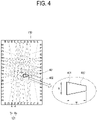
- the optical sensor 121 includes a plurality of light transmitters (or light emitting devices) Tx to emit the IR light, and a plurality of light receivers (or light receiving devices) Rx to receive the light from the light transmitter Tx.
- the plurality of light transmitters Tx and the plurality of light receivers Rx are arranged around the display 110, (e.g., arranged around the panel and face with each other).
- the plurality of light transmitters Tx and the plurality of light receivers Rx may be arranged along the edge of the screen, so that the IR light can be transmitted and obtained between the plurality of light transmitters Tx and the plurality of light receivers Rx as shown in FIG. 3 and FIG. 4 .
- the optical sensor 121 may form a matrix in front of the screen of the display 110 with the light transmitted and obtained between the plurality of light transmitters Tx and the plurality of light receivers Rx as described above.
- the form where the plurality of light transmitters Tx and the plurality of light receivers Rx are installed/arranged is not limited to those shown in FIG. 3 and FIG. 4 .
- the optical sensor 121 may be embodied in such a manner that the light transmitters Tx are arranged at the upper and left edges of the screen of the display 110, and the light receivers Rx are arranged at the lower and right edges.
- the IR light output from the light transmitter Tx is blocked by the pointer 200 in a region 401 touched with the pointer 200 and thus the output level of the blocked region is lowered. Therefore, it is possible to obtain coordinate information of the touched region 401.
- the coordinate information may be obtained as coordinate values (x, y) corresponding to an x coordinate and a y coordinate, respectively.
- the processor 160 may identify the touch position and touch size of the pointer 200, based on the obtained coordinate information.
- the processor 160 may identify the touch position based on the representative coordinate values corresponding to the center of the touched region 401.
- the processor 160 may employ various methods to identify the touch size.
- the processor 160 may recognize the outer points 402 of the touched region 401 to calculate the area where the touch input occurs, and thus identify the touch size based on the calculated area.
- the processor 160 may identify the touch size based on at least one between the width w and the height h of the touched region 401.
- FIG. 5 illustrates that a touch size is identified in a display apparatus according to an embodiment of the disclosure.
- the processor 160 may adjust the width (i.e., thickness) of the image displayed on the screen to correspond to at least one between the width w and the height h of the region 501 or 502.
- the processor 160 may obtain coordinate information corresponding to the touched region 501, based on the light transmitted and obtained by the optical sensor 121.
- the processor 160 may identify the touch position with predetermined coordinate values (x1, y1) based on the obtained coordinate information, and identify the touch size with a value (e.g., 15mm) based on the height h1 of the touched region 501.
- the processor 160 may adjust the width (or thickness) of the image displayed at the touch position (x1, y1) on the screen of the display 110 to correspond to the touch size (e.g., 15mm).
- the processor 160 may obtain coordinate information corresponding to the touched region 502, based on the light transmitted and obtained by the optical sensor 121.
- the processor 160 may identify the touch position with predetermined coordinate values (x2, y2) based on the obtained coordinate information, and identify the touch size with a value (e.g., 25mm) based on the width w2 of the touched region 502.
- the processor 160 may adjust the width (or thickness) of the image displayed at the touch position (x2, y2) on the screen of the display 110 to correspond to the touch size (e.g., 25mm).
- the processor 160 may identify the touch size based on information about the width w and the height h of a touched region 503, and adjust the width (or thickness) of the image displayed on the screen.
- the processor 160 may obtain coordinate information corresponding to the touched region 503, based on the light transmitted and obtained by the optical sensor 121.
- the processor 160 may identify the touch position with predetermined coordinate values (x3, y3) based on the obtained coordinate information, and identify the touch size (e.g., identified as 10mm) based on values (e.g., 7m, and 7m) corresponding to the width w3 and height h3 of the touched region 503.
- the processor 160 may adjust the width (or thickness) of the image displayed at the touch position (x3, y3) on the screen of the display 110 to correspond to the touch size (e.g., 10mm).
- the image processor 130 may generate an image signal so that an image can be displayed in the touched region by the pointer 200 on the screen, based on the touch position and the touch size caused by the pointer 200.
- the image signal processed by the image processor 130 may be transmitted to the display 110, and the display 110 may be driven by the image signal to display an image on the screen.
- the image signal processed by the image processor 130 may be based on data stored in the memory 150, which may be a nonvolatile storage 150 such as a flash memory, or a hard disk drive, etc.
- an image signal may be generated to display an image of which a width is successively adjusted corresponding to an identified touch size along a trace of the successive touch positions.
- the display apparatus 100 may display the image, of which the width is successively adjusted corresponding to the touch sizes of the pointer 200 along the trace of the successive touch positions moved as described above, on the screen of the display 110, thereby allowing a user to experience an analog input of directly writing or drawing on the screen.
- the image processor 130 may process an image (e.g. a writing image or a drawing image) displayed on the screen of the display 110, and generate an image file having a predetermined corresponding format.
- the generated image file may be stored in the memory 150, or may be transmitted to at least one external apparatus through the communication interface 140 so as to be shared (e.g., among participants in a meeting, a class, etc.).
- the image processor 130 may perform various preset video/audio processes with regard to an image signal of content.
- the image processor 130 may output a signal generated or combined by performing the processes to the display 110, thereby displaying an image corresponding to the output signal on the screen.
- the image processor 130 may include a decoder configured to decode an image signal to correspond to an image format of the display apparatus 100, and a scaler configured to adjust the image signal to match the output resolution of the display 110.
- the decoder may for example be embodied as a moving picture experts group (MPEG) decoder, and there are no limits to the kinds of content to be processed by the image processor 130 in the disclosure.
- the content to be processed by the image processor 130 may include not only a moving image such as a video but also a still image such as a picture.
- the image processor 130 may be embodied as a group of individual elements for independently performing such processes, or embodied as included in a main system-on-chip (SoC) where many functions are integrated.
- SoC system-on-chip
- the main SoC may further include the processor 160 embodied as at least one microprocessor or central processing unit (CPU).
- the image processor 130 may be embodied as a printed circuit board (PCB) where various chipsets, memories, electronic parts, wirings and the like circuit elements are mounted on a board to carry out such processes.
- PCB printed circuit board
- both the image processor 130 and the processor 160 may be provided in a single board.
- the image processor 130 and the processor 160 may alternatively be provided in a plurality of PCBs connected to each other for communication.
- the communication interface 140 may perform wired or wireless communication with at least one external apparatus.
- an external apparatus to be subjected to communication with the communication interface 140 may include an active pen capable of autonomously generating a signal.
- the active pen may include a sensor for detecting an IR signal, and the display apparatus 100 may wirelessly obtain position data, which is generated based on the IR signal detected by the sensor of the active pen, from the active pen through the communication interface 140.
- the communication interface 140 may transmit an image file having a predetermined format, into which an image (e.g. a writing image or a drawing image) displayed on the screen of the display 110 may be processed, to one or more external apparatuses.
- an image e.g. a writing image or a drawing image
- the communication interface 140 may be embodied as a communication circuitry including communication modules (e.g., a software (S/W) module, a chip, etc.) corresponding to various communication protocols.
- communication modules e.g., a software (S/W) module, a chip, etc.
- the communication interface 140 may include a wireless local area network (WLAN) interface.
- the WLAN interface may wirelessly be connected to the external apparatus through an AP under control of the processor 160.
- the WLAN interface may include a Wi-Fi communication interface.
- the communication interface 140 may include a short-range communication interface that supports wireless direct communication between the display apparatus 100 and the external apparatus without the AP.
- the short-range communication interface may support at least one among Wi-Fi direct, Bluetooth, Bluetooth low energy, RF communication, IR data association (IrDA), Zigbee, ultra-wideband (UWB), or near field communication (NFC).
- the memory 150 may store address information (e.g. media access control (MAC) address or IP address) about the external apparatus to be subjected to the communication.
- MAC media access control
- the communication interface 140 may be provided to perform the wireless communication with the external apparatus through at least one of the WLAN interface or the short-range communication interface according to performance.
- the communication interface 140 may include Ethernet or the like wired communication interface. According to still another embodiment, the communication interface 140 may include one or more communication interfaces based on various communication methods such as long-term evolution (LTE) and the like mobile communication, electromagnetic (EM) communication involving a magnetic field, visible light communication, or soundwave communication, etc.
- LTE long-term evolution
- EM electromagnetic
- the communication interface 140 may include a connector via which the display apparatus 100 and the external apparatus are connected by a wire.
- the connector may be embodied as a communication circuitry including data input/output interfaces where communication interfaces (e.g., a S/W module, a chip, etc.), a port, etc. are combined corresponding to various communication protocols.
- communication interfaces e.g., a S/W module, a chip, etc.
- port e.g., a port, etc.
- the connector may be embodied in various forms corresponding to standards of signals obtained in the display apparatus 100, and may be for example configured to transmit and obtain data by a wire through one or more of: the HDMI, the DVI, the DP, the D-sub, the Composite video, the Component video, the Super video, the SCART, or the USB, etc.
- the communication interface 140 may obtain content from a source apparatus.
- the memory 150 may be configured to store various pieces of data of the display apparatus 100.
- the memory 150 may be actualized by a nonvolatile memory (or a writable ROM) which can retain data even though the display apparatus 100 is powered off, and mirror changes. That is, the memory 150 may be provided as at least one among a flash memory, an electrically programmable ROM (EPROM) or an electrically erasable and programmable ROM (EEPROM).
- the memory 150 may further include a volatile memory a dynamic random access memory (DRAM) or a static RAM (SRAM), of which reading or writing speed for the display apparatus 100 is faster than that of the nonvolatile memory.
- DRAM dynamic random access memory
- SRAM static RAM
- Data stored in the memory 150 may for example include not only an operating system (OS) for driving the display apparatus 100 but also one or more of: various software, programs, applications, image data, or appended data, etc. executable on the OS.
- OS operating system
- the memory 150 may be configured to store an application for functioning as the interactive whiteboard.
- the memory 150 may be configured to store an image file having a predetermined format, into which an image (e.g. a writing image or a drawing image) displayed on the screen of the display 110 may be processed.
- an image e.g. a writing image or a drawing image
- the memory 150 may be configured to store graphic data obtained from the outside in the display apparatus 100 or autonomously provided by the display apparatus 100.
- the graphic data may be output to the display 110 as an image signal processed by the image processor 130, and may be displayed as graphics such as one or more of: an on-screen display (OSD), or a graphic user interface (GUI, hereinafter also referred to as "user interface (UI)”), etc. in a certain area on the screen.
- OSD on-screen display
- GUI graphic user interface
- UI user interface
- the processor 160 may perform control for operating general elements of the display apparatus 100.
- the processor 160 may identify the touch position of the pointer 200 on the screen, based on the light transmitted and obtained by the optical sensor 121 provided as the touch sensor 120, and may control the image processor 130 to display an image on the screen along the successive touch positions (also referred to as the moving touch position) as the touch position of the identified pointer 200 is moved.
- the processor 160 may identify the touch size of the pointer 200 based on the light transmitted and obtained while the touch position is moved, and control the image processor 130 to adjust the width (or thickness) of at least a portion of the image displayed on the screen corresponding to a variation in the identified touch size of the pointer 200.
- the processor 160 may perform control to operate general elements of the display apparatus 100.
- the processor 160 may execute a control program (or an instruction) for performing such control operations.
- the processor 170 may include at least one universal processor that loads at least a part of a control program from a nonvolatile memory, in which the control program is installed, to a volatile memory, and executes the loaded control program, and may for example be actualized by one or more of: a central processing unit (CPU), an application processor (AP), or a microprocessor.
- CPU central processing unit
- AP application processor
- microprocessor a microprocessor
- the processor may include a single core, or multiple core (e.g., a dual core, a triple core, or a quad core, or the like multiple core).
- the processor may include a plurality of processors, for example, a main processor and a sub processor that operates in a sleep mode (during which only standby power is supplied without operation of the display apparatus).
- the processor, the ROM, and the RAM may be connected to one another through an internal bus, and the ROM and the RAM may belong to the memory 150.
- the processor as an example of the processor 160, may be actualized as included in the main SoC mounted to the PCB internally provided in the display apparatus 100.
- the main SoC may further include the image processor 130.
- the control program may include a program(s) achieved by at least one of a basic input/output system (BIOS), a device driver, an OS, a firmware, a platform, or an application.
- the application may be previously installed or stored in the display apparatus 100 based on the display apparatus 100 being manufactured, or may be installed in the display apparatus 100 on the basis of application data obtained from the outside based on it being required in the future.
- the application data may for example be downloaded from an external server such as an application market to the display apparatus 100.
- an external server is merely an example of the computer program product according to the disclosure, but not limited thereto.
- the operation of the processor 160 may be actualized by a computer program stored in the computer program product (not shown) provided separately from the display apparatus 100.
- the computer program product may include a non-transitory computer readable medium or a memory in which an instruction corresponding to a computer program is stored.
- the computer program product may also include a processor. Based on the instruction being issued by the processor, an image may be displayed on the screen along the moving touch position (successive touch positions) of the pointer 200, the touch size of the pointer 200may be identified based on the light transmitted and obtained while the touch position is moved, and the width of the image displayed on the screen may be adjusted corresponding to the variation in the identified touch size.
- the display apparatus 100 may download and execute the computer program stored in a separate computer program product and perform the operation of the processor 160.
- the operation of the processor 160 may be carried out by a computer-readable program stored in the recording medium.
- the program i.e. data stored in the recording medium
- the program may be directly accessed and executed by the processor 160, or may be downloaded into the display apparatus 100 via a transmission medium actualized by a wired/wireless network in which the computer systems are connected to one another and executed, thereby carrying out operation.
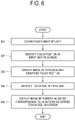
- FIG. 6 illustrates a control method of a display apparatus according to an embodiment of the disclosure.
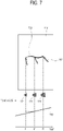
- FIGS. 7 and 8 illustrate examples of displaying images corresponding to touch sizes by a control method of a display apparatus according to an embodiment of the disclosure.
- a display apparatus 100 obtains a user's touch input made on the screen of the display 110 by using a predetermined pointer 200 (601).
- the obtained touch input may include successive touches (e.g. a writing input or a drawing input) corresponding to moving touch positions on the screen, by using the pointer 200.
- the pointer 200 may comprise one or more of: a part of a user's body 201 such as a thumb, one or more fingers, or a palm, etc.) or a device 202 such as a brush (e.g. a painting brush).
- the display apparatus 100 Based on a user's touch input being made on the screen in the operation 601, the display apparatus 100 identifies the touch position of the pointer 200 on the screen of the display 110 (602). As shown in FIG. 3 and FIG. 4 , the display apparatus 100 includes the optical sensor 120 for transmitting and obtaining light to scan the screen of the display 110, the processor 160 may identify the touch position (i.e. coordinate values) of the pointer 200 on the screen, based on the light transmitted and obtained by the optical sensor 120.
- the display apparatus 100 displays an image on the screen of the display 110 according to the touch positions identified in the operation 602 (603). Based on the successive touches (e.g. a writing input or a drawing input) using the pointer 200 being made on the screen in the operation 601, the processor 160 may display an image 730 or 830 (e.g. the writing image or the drawing image) on the screen of the display 110 according to the movement in the touch position of the identified pointer 200. In other words, as shown in FIG. 7 and FIG. 8 , the image 730 or 830 may be displayed corresponding to the touch position moving on the screen of the display 110 along the trace that a user writes or draws on the screen with the pointer 200.
- the image 730 or 830 may be displayed corresponding to the touch position moving on the screen of the display 110 along the trace that a user writes or draws on the screen with the pointer 200.
- the processor 160 of the display apparatus 100 identifies the touch size of the pointer 200 on the screen (604). As described with reference to FIG. 3 and FIG. 4 , the processor 160 may identify the varying touch size of the pointer 200, based on the light transmitted and obtained by the optical sensor 120 while the touch position is moving according to the successive touches obtained in the operation 601. The processor 160 may employ various methods to identify the touch size. For example, as described with reference to FIG. 5 , the touch size may be identified based on at least one between the width w and the height h of the region touched by the pointer 200 on the screen.
- the processor 160 may display the image displayed on the screen of the display 110 by adjusting the width of the image based on variation in the touch size identified in the operation 604 (605). Based on the successive touches (e.g. a writing input or a drawing input) varied in angle of the pointer 200 or pressure against the screen are obtained on the screen in the operation 601, the processor 160 may display the image 730 or 830 (e.g. the writing image or the drawing image), the width of which is adjusted corresponding to the variation in the touch size based on the movement of the touch position of the pointer 200, on the screen of the display 110.
- the writing or drawing image 730 or 830 the thickness of which is varied, may be displayed at the moving touch positions on the screen of the display 110 along the trace that a user uses the pointer 200 to write or draw on the screen.
- a user employs a brush or the like device 202 as the pointer 200 to make a user input of writing or drawing in the form 710 of increasing the touch size of the pointer 200 on the screen of the display 110.
- a brush or the like device 202 as the pointer 200 to make a user input of writing or drawing in the form 710 of increasing the touch size of the pointer 200 on the screen of the display 110.
- the touch sizes 721, 722 and 723 of the pointer 200 are different from one another, i.e. gradually increased at points t1, t2 and t3 in time. Therefore, the width (thickness) of the image (i.e. the writing image or the drawing image) 730 may be gradually increased as shown in FIG. 7 , and displayed on the screen of the display 110.
- a user may employ the brush or the like device 202 as the pointer 200 to make a user input of writing or drawing in the form 810 of varying the touch size of the pointer 200 on the screen of the display 110.
- the touch sizes 821, 822 and 823 of the pointer 200 are different from one another (e.g., increased and then decreased at points t4, t5 and t6 in time). Therefore, the image (the writing image or the drawing image) 730, the width (thickness) of which is gradually increased as shown in FIG. 7 , may be displayed on the screen of the display 110. Therefore, the image (i.e. the writing image or the drawing image) 830, the width (thickness) of which is increased and then decreased as shown in FIG. 8 , may be displayed on the screen of the display 110.
- the display apparatus 100 may display the image (i.e. the writing image or the drawing image), the width of which is dynamically varied along the trace of the successive touch inputs like a case where a user directly writes or draws on the screen of the display 110, on the screen of the display 110, thereby allowing a user to experience natural analog writing or drawing.
- the image i.e. the writing image or the drawing image
- the display apparatus 100 may represent the width (or thickness) of the image as the number of pixels corresponding to the actual touch size of the pointer 200 according to the size and resolution of the display 110, i.e. the panel.
- the display apparatus 100 may identify a pixel size (e.g., 1 pixel area) based on the size and resolution of the display panel 110 as shown in the following Table 1.
- a pixel size e.g., 1 pixel area
- Table 1 Size Active area(mm) Resolution (pixel) 1 Pixel area(mm) H V H V H V 43 inches 941.18 529.42 3840 2160 0.2451 0.2451 55 inches 1209.6 680.4 3840 2160 0.315 0.315 75 inches 1538.88 865.62 3840 2160 0.4008 0.4008
- a display of 43 inches has a length of 941.18mm in a horizontal direction H and a length of 529.42mm in a vertical direction V, and the number of pixels in the horizontal direction H is 3840 and the number of pixels in the vertical direction V is 2160. Therefore, sizes in the horizontal direction H and the vertical direction V per pixel are respectively 0.2451mm and 0.2451mm, thereby obtaining one pixel area of 0.2451 ⁇ 0.2451mm.
- Table 1 shows the pixel sizes of three types of display by way of example, but the disclosure is applied regardless of the size/resolution of the display. Therefore, the pixel sizes may be identified with regard to the displays of various sizes/resolutions.
- the processor 160 calculates the number of pixels corresponding to the touch size of the pointer 200 on the screen while allowing for the size of the display 110, and control the display 110 to display an image, the width of which is represented with the calculated number of pixels, in the touch position on the screen.
- the actual physical touch size of the pointer 200 is reflected in variation in the width (i.e., thickness) of the image in real time, and therefore the image is displayed very similarly to a case of writing or drawing with an actual brush.
- the processor 160 may control the display 110 to make the image displayed in the touch position on the screen be represented with the width of, for example, 130 pixels.
- the processor 160 may control the display 110 to make the image displayed in the touch position on the screen be represented with the width of, for example, 324 pixels.
- Table 2 shows, as an example, the number of pixels corresponding to the touch size by way of example in three types of display, but the disclosure is applied regardless of the size/resolution of the display. Therefore, the number of pixels may be identified with regard to the touch sizes in the displays having various sizes/resolutions. Further, Table 2 shows several touch sizes within a range of 2 ⁇ 30mm by way of example, and the touch size identified in the disclosure may be varied depending on the size, angle, etc. that the tip of the pointer 200 has. Thus, the touch size is not limited to that shown in Table 2.
- the processor 160 may make the width (or thickness) of the image displayed at the touch position (x1, y1) on the screen of the display 110 be represented with, for example, 194 pixels corresponding to the touch size of, for example, 15mm. Further, the processor 160 may make the width (or thickness) of the image displayed at the touch position (x2, y2) on the screen of the display 110 be represented with, for example, 324 pixels corresponding to the touch size of, for example, 25mm, and the width (or thickness) of the image displayed at the touch position (x3, y3) on the screen of the display 110 be represented with, for example, 130 pixels corresponding to the touch size of, for example, 10mm.
- the processor 160 may display an image, a width of which is successively adjusted based on the number of pixels corresponding to the identified touch size along the trace of the moving touch positions.
- the display apparatus 100 may display an image, a width of which is based on the number of pixels corresponding to an actual physical touch size of the pointer 200 and is successively adjusted along the trace of the touch position moved as described above, on the screen of the display 110, so that the variation in the width (or the thickness) of the image can be represented very similarly to a case of writing or drawing with an actual brush or pen/pencil.
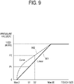
- FIGS. 9 and 10 illustrate conversion between a touch size and a pressure value in a display apparatus according to an embodiment of the disclosure.
- the display apparatus 100 may convert the identified touch size into a pressure value P, and may control the display 110 to display the image of which the width (or thickness) is adjusted based on the converted pressure value P.
- the display apparatus 100 may convert the identified touch size into a pressure value P, and may control the display 110 to display the image of which the width (or thickness) is adjusted based on the converted pressure value P.
- the processor 160 may normalize a touch size between the preset minimum and maximum values into a pressure value in an input-allowed range, thereby converting the touch size into the pressure value.
- the processor 160 may convert a predetermined touch size S1 into a matching pressure value P1 based on a linear graph 901 showing a relation between the touch size and the pressure value as shown in FIG. 9 .
- the touch size may be converted into the pressure value having a level of, for example, 293. Further, based on the touch size being identified as, for example, 20mm in a state that the range of the pressure value is set to, for example, 0 ⁇ 4,095 levels, the touch size may be converted into the pressure value having a level of, for example, 2,633.
- the processor 160 may make the width of the image displayed at the touch position on the screen of the display 110 be adjusted corresponding to the converted pressure value.
- the processor 160 may convert a predetermined touch size S2 into a matching pressure value P2 based on a curved graph 902 showing a relation between the touch size and the pressure value as shown in FIG. 9 .
- the processor 160 may make the width of the image displayed at the touch position on the screen of the display 110 be adjusted corresponding to the converted pressure value P2.
- the curved form is not limited to that shown in FIG. 9 , but may have various forms according to the kinds of application using the pressure value.
- the processor 160 may control the touch size identified by the optical sensor 121 to be converted into the pressure value based on the application using the pressure value being executed.
- the application operating based on the resistive touch detection method using the active pen can be installed and executed even in the display apparatus 100 according to the disclosure with the optical sensor 121 scanning the screen of the display 110, and it is thus possible to use the function of the application.
- the processor 160 may control the image (e.g., the writing image or the drawing image) to be displayed on the screen of the display 110 while having a width of, for example, 30mm as the maximum value of the touch size.
- the image e.g., the writing image or the drawing image
- the processor 160 may convert the maximum value of the touch size into a pressure value of, for example, 1,023 corresponding to, for example, 30mm, thereby controlling the image (e.g. the writing image or the drawing image) to be displayed on the screen of the display 110 while having a width corresponding to the matching pressure value.
- the display apparatus 100 may be embodied to obtain a user input for setting an identifiable touch size.
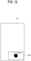
- FIGS. 11 and 12 illustrate user interfaces (Ul) for setting a touch size in a display apparatus according to the present disclosure.
- the processor 160 may control a UI 1101, through which selection is allowed to be set or change the maximum value (i.e. the maximum size) for the touch size of the pointer 200, to be displayed in a certain region on the screen of the display 110.
- the maximum value i.e. the maximum size
- a user may make a user input to set or change the touch size identifiable by the display apparatus 100.
- the user input for making selection in the UI 1101 may be obtainable in many ways.
- the selection may be made by obtaining a touch input using the pointer 200 on the UI 1101, or controlling a user input unit including a remote input device in a state that the UI 1101 is selected.
- the processor 160 may control a UI 1201, through which the maximum value (i.e. the maximum size) for the touch size of the pointer 200 can be input, to be displayed in a certain region on the screen of the display 110 as shown in FIG. 12 .
- the user input for inputting the maximum value of the touch size may be obtainable in many ways.
- the user input may be achieved by directly writing the size or controlling a button of a user input unit including a remote input device such as a remote controller.
- the processor 160 may adjust the width of the image displayed on the screen of the display 110 based on the change in the touch size of the pointer 200 within a range set by the input maximum value.
- the processor 160 may control the image (e.g. the writing image or the drawing image) to be displayed on the screen of the display 110 while having a width of, for example, 20mm as the maximum value of the touch size.
- the image e.g. the writing image or the drawing image
- the display apparatus 100 it may further be possible to set a touch size for an eraser mode.
- the processor 160 may control a Ul selectable for inputting a threshold value for operating the eraser mode, i.e. the minimum value (i.e. the minimum size) for the touch size of the pointer 200 to be displayed in a certain region on the screen of the display 110.
- a specific size e.g., 60mm, 70mm, or etc.
- the minimum value is not limited to this value.
- the processor 160 may delete an image displayed on the screen of the display 110 based on movement of the touch position of the identified pointer 200.
- the processor 160 may identify the region touched by the pointer 200 based on the light transmitted and obtained by the optical sensor 121. Further, the processor 160 may perform an operation of deleting, i.e., erasing at least a portion of the image displayed in the identified region on the screen of the display 110.
- deleting i.e., erasing at least a portion of the image displayed in the identified region on the screen of the display 110.
- the display apparatus 100 may adjust the width of at least a portion of the image displayed on the screen of the display 110 based on the variation in the identified touch size.
- FIG. 13 illustrates a UI for selecting a touch input mode in a display apparatus according to the present disclosure.
- the touch input mode of the display apparatus 100 includes a real-time variable touch-size mode and a fixed touch-size mode, and the processor 160 may display the UI including menu items 1310 and 1320 for selecting one of the two modes on the screen of the display 110.
- a user may select one of check boxes 1311 and 1321 respectively corresponding to the modes, so that the display apparatus 100 can operate in the selected mode.
- the processor 160 controls the display 110 to display an image having a width adjusted corresponding to variation in the touch size of the pointer 200.
- the writing image or the drawing image may be displayed with the width (or thickness) being varied corresponding to the identified touch size in the moving touch position on the screen of the display 110 along a trace that a user writes or draws on the screen with the pointer 200 until the pointer 200 on the screen of the display 110 is released from an initial touch.
- the processor 160 controls the display 110 to display an image with a fixed width even though the touch size of the pointer 200 is varied.
- the writing image or the drawing image may be displayed with the width (or thickness) fixed corresponding to the initial touch in the moving touch position on the screen of the display 110 along a trace that a user writes or draws on the screen with the pointer 200 until the pointer 200 on the screen of the display 110 is released from the initial touch.
- the display apparatus 100 may allow a user to select the touch input mode as described above and selectively experience the analog writing or drawing as necessary for a purpose.
- the display apparatus 100 may control the display 110 to display an image with a changed width (or thickness) based on a touch input using the pointer 200 being maintained in a specific position on the screen of the display 110 for more than a predetermined period of time.
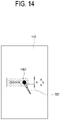
- FIG. 14 illustrates a change in a width of at least a portion of an image in a display apparatus according to the present disclosure.
- the processor 160 may control the display 110 to change the width a of the image displayed corresponding to the identified touch size (e.g., to increase the width a of the image into a width b).
- the processor 160 may control the writing image or the drawing image with the increased width b to be displayed on the screen of the display 110 in accordance with the moving touch position.
- the processor 160 may control the display 110 to change the width of at least a portion of the image displayed on the screen in accordance with a rate of the change.
- the display apparatus 100 may display the writing image or the drawing image with a width (or thickness) larger than the identifiable touch size.
- the processor 160 may control the display 110 to change a color of the image (e.g., to increase brightness or saturation) without changing the width a of the image.
- the processor 160 may control the writing image or the drawing image with the width a and the changed color to be displayed on the screen of the display 110 in accordance with the moving touch position.
- the processor 160 may control the display 110 to change the width of at least a portion of the image displayed on the screen in accordance with a rate of the change.
- FIG. 15 is a flowchart showing a control method of a display apparatus according to another embodiment of the disclosure.
- the display apparatus 100 performs touch detection based on the optical sensor 121 provided as the touch sensor 120, arranged around the display 110 and transmitting and obtaining light (1501).
- the processor 160 Based on the touch detection, the processor 160 identifies whether a touch occurs on the screen of the display 110 (1502). Here, the processor 160 may detect an initial touch based on the writing input, the drawing input or the like successive touches with the pointer 200.
- the processor 160 Based on the touch occurring in the operation 1502, the processor 160 identifies the touch position and the touch size of the pointer 200 on the screen of the display 110 (1503). The processor 160 may identify a position at which the initial touch is made on the screen, and the touch size in the position.
- the processor 160 controls an image having a width (or thickness) corresponding to the touch size identified in the operation 1503 in the touch position identified in the operation 1503 to be displayed on the screen of the display 110 (1504).
- the processor 160 may identify whether the touch position identified in the operation 1503 is moved (1505). The processor 160 may identify whether the touch position is moved according to whether a successive touch following the initial touch is detected based on light transmitted and obtained by the optical sensor 121.
- the processor 160 may identify whether the touch size identified in the operation 1503 is varied (1506).
- the processor 160 may identify whether the touch size is varied at the position identified in the operation 1503 based on the light transmitted and obtained by the optical sensor 121. For example, based on a user making the pointer 200 be in contact with a specific position on the screen of the display 110 and pressing the pointer against the screen, or changing the angle of the pointer 200, the processor 160 may identify that the touch size is varied.
- the processor 160 may control an image with a width varied corresponding to the touch size varied in the operation 1506 to be displayed at a touch position of the initial touch identified in the operation 1503, i.e. at the current position (1507). Therefore, the image with the width more increased or decreased than that of the image in the operation 1504 can be displayed on the screen of the display 110.
- the processor 160 may detect whether the touch in the operation 1502 is terminated (1511). The processor 160 may detect the termination of the touch based on the initial touch in the operation 1502 being released, based on the light transmitted and obtained by the optical sensor 121.
- the processor 160 may identify whether the touch size identified in the operation 1503 is varied (1508). Like the operation 1506, the processor 160 may identify whether the touch size is varied at the position identified in the operation 1503, based on the light transmitted and obtained by the optical sensor 121. For example, based on a user making the pointer 200 being in contact with the screen of the display 110 be pressed against the screen, or based on the angle of the pointer 200 being changed, the processor 160 may identify that the touch size is varied.
- the processor 160 may successively display an image with a fixed width from the touch position of the initial touch identified in the operation 1503 to the touch position moved in the operation 1505 (1509). Therefore, as shown in FIG. 1 , the writing image or the drawing image based on the successive touches may be displayed on the screen of the display 110.
- the processor 160 may display an image with a width varied depending on the touch size varied in the operation 1506, from the touch position of the initial touch identified in the operation 1503 to the touch position moved in the operation 1505 (1510). Therefore, as shown in FIGS. 7 and 8 , the writing image or the drawing image based on the successive touches may be displayed with a continuously variable width on the screen of the display 110.
- the processor 160 may identify whether the touch in the operation 1502 is terminated while displaying the images of the operations 1507, 1509 and 1510 (1511).
- the processor 160 may identify that the touch is terminated based on the initial touch in the operation 1502 being released, based on the light transmitted and obtained by the optical sensor 121. Therefore, the writing image or the drawing image, in which the movement of the touch position or the variation in the touch size is successively reflected, can be displayed on the screen of the display 110 until the writing input, the drawing input or the like successive touches are released from the initial touch.
- the display apparatus 100 may feed the image (e.g. the writing image or the drawing image), of which the width is freely variable along the trace of the successive touch inputs, back to the screen of the display 110, thereby allowing a user to feel like direct writing or drawing on the screen of the display 110.
- the image e.g. the writing image or the drawing image
- the width is freely variable along the trace of the successive touch inputs
- the width of the image is represented with the number of pixels corresponding to the actual touch size of the pointer 200 based on the size or resolution of the display 110, thereby allowing a user to experience more natural analog writing/drawing.
- the touch size of the identified pointer 200 may be converted into a pressure value, so that the display apparatus 100 can use a function of an application designed to operate in a resistive touch detection type apparatus using an active pen.
- a display apparatus of the disclosure a method of controlling the same, and a recording medium thereof, in which an image is controlled to be displayed with a width freely variable along a trace of successive touch inputs, thereby making a user experience direct writing or drawing on a screen.
Landscapes
- Engineering & Computer Science (AREA)
- General Engineering & Computer Science (AREA)
- Theoretical Computer Science (AREA)
- Human Computer Interaction (AREA)
- Physics & Mathematics (AREA)
- General Physics & Mathematics (AREA)
- Controls And Circuits For Display Device (AREA)
- User Interface Of Digital Computer (AREA)
- Position Input By Displaying (AREA)
Claims (13)
- Anzeigevorrichtung (100), umfassend:eine Anzeige (110);einen optischen Sensor (121), der eine Vielzahl von Lichtsendern und eine Vielzahl von Lichtempfängern umfasst, die um die Anzeige herum angeordnet, einander zugewandt und dafür konfiguriert sind, Licht zu übertragen und zu empfangen; undeinen Prozessor (160), der konfiguriert ist, um:eine Berührungsposition eines Zeigers (200) auf einem Bildschirm der Anzeige (110) basierend auf Licht, das von dem optischen Sensor (121) übertragen und erhalten wird, zu identifizieren,eine Berührungsgröße des Zeigers (200) basierend auf Licht zu identifizieren, das von dem optischen Sensor (121) übertragen und erhalten wird, undzu bewirken, dass die Anzeige (110) basierend auf einer Bewegung des Zeigers (200) ein Bild anzeigt, das der identifizierten Berührungsgröße entlang Berührungspositionen aufeinanderfolgender Berührungen auf dem Bildschirm entspricht,dadurch gekennzeichnet, dass der Prozessor konfiguriert ist, umbasierend auf einer Größe und einer Auflösung der Anzeige (110) die Anzahl von Pixeln zu identifizieren, die der identifizierten Berührungsgröße des Zeigers (200) entsprechen, undeine Breite von mindestens einem Teil des auf dem Bildschirm der Anzeige (110) angezeigten Bildes basierend auf der identifizierten Anzahl von Pixeln anzupassen, undwobei der Prozessor (160) ferner konfiguriert ist, um:basierend auf einem ausgewählten Modus mit veränderlicher Berührungsgröße in Echtzeit zu bewirken, dass die Anzeige (110) ein Bild anzeigt, dessen Breite entsprechend einer Veränderung in der identifizierten Berührungsgröße des Zeigers auf dem Bildschirm entlang Berührungspositionen aufeinanderfolgender Berührungen variiert wird, während der Zeiger bewegt wird,basierend auf der Auswahl eines Modus mit fester Berührungsgröße zu bewirken, dass die Anzeige (110) ein Bild mit einer festen Breite entsprechend einer anfänglichen Berührung aufeinanderfolgender Berührungen auf dem Bildschirm entlang Berührungspositionen aufeinanderfolgender Berührungen anzeigt, während der Zeiger bewegt wird.
- Anzeigevorrichtung (100) nach Anspruch 1, wobeider optische Sensor (121) ferner so konfiguriert ist, dass er die Änderung der Berührungsgröße des Zeigers (200) bei den aufeinanderfolgenden Berührungen des Zeigers (200) identifiziert, undder Prozessor (121) ferner dazu konfiguriert ist, eine Breite eines auf dem Bildschirm der Anzeige (110) angezeigten Schrift- oder Zeichenbildes basierend auf der Veränderung der identifizierten Berührungsgröße bei den aufeinanderfolgenden Berührungen anzupassen.
- Anzeigevorrichtung (100) nach Anspruch 1, wobei der Prozessor (160) ferner konfiguriert ist, um die Berührungsgröße basierend auf mindestens einem zwischen einer Breite und einer Höhe eines auf dem Bildschirm der Anzeige (110) durch den Zeiger (200) berührten Bereichs zu identifizieren.
- Anzeigevorrichtung (100) nach Anspruch 1, wobei der optische Sensor (121) ferner konfiguriert ist, um eine Matrix vor dem Bildschirm der Anzeige (110) mit Licht zu bilden, das zwischen der Vielzahl von Lichtsendern und der Vielzahl von Lichtempfängern übertragen und erhalten wird.
- Anzeigevorrichtung (100) nach Anspruch 1, wobei der Zeiger (200) mindestens eines von Folgendem umfasst: einen Daumen, einen oder mehrere Finger oder eine Handfläche eines Benutzers oder eine Vorrichtung vom passiven Typ, einschließlich eines Stifts oder einer Bürste.
- Anzeigevorrichtung (100) nach Anspruch 1, wobei der Prozessor (160) ferner konfiguriert ist, um die identifizierte Berührungsgröße in einen Druckwert umzuwandeln und um die Breite zumindest des Teils des Bildes basierend auf dem umgewandelten Druckwert anzupassen.
- Anzeigevorrichtung (100) nach Anspruch 1, wobei der Prozessor (160) ferner konfiguriert ist, um die Breite von mindestens dem Abschnitt des Bildes, der der Veränderung der Berührungsgröße entspricht, basierend darauf, dass die identifizierte Berührungsgröße innerhalb eines voreingestellten Bereichs liegt, anzupassen.
- Anzeigevorrichtung (100) nach einem der Ansprüche 1 bis 7, wobei der Prozessor (160) ferner konfiguriert ist, um zu steuern, dass das auf dem Bildschirm angezeigte Bild entsprechend den Berührungspositionen der aufeinanderfolgenden Berührungen der Berührungsposition des Zeigers basierend darauf gelöscht wird, dass die identifizierte Berührungsgröße größer als ein voreingestellter Schwellenwert ist.
- Verfahren zum Steuern einer Anzeigevorrichtung (100), wobei das Verfahren Folgendes umfasst:Identifizieren einer Berührungsposition eines Zeigers (200) auf einem Bildschirm einer Anzeige (110), basierend auf Licht, das von einem optischen Sensor (121) übertragen und erhalten wird, der eine Vielzahl von Lichtsendern und eine Vielzahl von Lichtempfängern umfasst, die um die Anzeige (110) herum angeordnet, einander zugewandt und dazu konfiguriert sind, Licht zu übertragen und zu empfangen;Identifizieren einer Berührungsgröße des Zeigers (200) basierend auf Licht, das von dem optischen Sensor (121) übertragen und erhalten wird,Anzeigen eines Bildes, das der identifizierten Berührungsgröße auf dem Bildschirm entspricht, entlang Berührungspositionen aufeinanderfolgender Berührungen, basierend auf einer Bewegung des Zeigers (200);dadurch gekennzeichnet, dass das Identifizieren der Berührungsgröße Folgendes umfasst:Identifizieren der Anzahl von Pixeln, die der identifizierten Berührungsgröße entsprechen, basierend auf einer Größe und einer Auflösung der Anzeige (110), undAnpassen einer Breite von mindestens einem Teil des auf dem Bildschirm der Anzeige (110) angezeigten Bildes basierend auf der identifizierten Anzahl von Pixeln,wobei das Anzeigen des Bildes ferner Folgendes umfasst:basierend auf einem ausgewählten Modus mit veränderlicher Berührungsgröße in Echtzeit, Anzeigen eines Bilds, dessen Breite entsprechend der Veränderung der identifizierten Berührungsgröße des Zeigers auf dem Bildschirm der Anzeige (110) entlang Berührungspositionen aufeinanderfolgender Berührungen variiert wird, während der Zeiger bewegt wird,basierend auf der Auswahl eines Modus mit fester Berührungsgröße, Anzeigen eines Bildes mit einer festen Breite entsprechend einer anfänglichen Berührung von aufeinanderfolgenden Berührungen auf dem Bildschirm der Anzeige (110) entlang Berührungspositionen von aufeinanderfolgenden Berührungen, während der Zeiger bewegt wird.
- Verfahren nach Anspruch 9, wobeidas Identifizieren der Berührungsgröße das Identifizieren der Veränderung der Berührungsgröße des Zeigers (200) bei den aufeinanderfolgenden Berührungen des Zeigers umfasst, unddas Anpassen der Breite des Bildes das Anpassen einer Breite eines auf dem Bildschirm der Anzeige (110) angezeigten Schrift- oder Zeichenbildes basierend auf der Veränderung der identifizierten Berührungsgröße bei den aufeinanderfolgenden Berührungen umfasst.
- Verfahren nach Anspruch 9, wobei das Identifizieren der Berührungsgröße das Identifizieren der Berührungsgröße basierend auf mindestens einem zwischen einer Breite und einer Höhe eines auf dem Bildschirm der Anzeige (110) durch den Zeiger (200) berührten Bereichs umfasst.
- Verfahren nach Anspruch 9, ferner umfassend:Umwandeln der identifizierten Berührungsgröße in einen Druckwert; undAnpassen der Breite von mindestens dem Teil des Bildes basierend auf dem umgewandelten Druckwert.
- Verfahren nach einem der Ansprüche 9 bis 12, wobei das Anpassen der Breite des mindestens einen Teils des Bildes das Anpassen der Breite des mindestens einen Teils des Bildes entsprechend der Veränderung der Berührungsgröße basierend darauf umfasst, dass die identifizierte Berührungsgröße innerhalb eines voreingestellten Bereichs liegt.
Applications Claiming Priority (1)
| Application Number | Priority Date | Filing Date | Title |
|---|---|---|---|
| KR1020180148673A KR102625830B1 (ko) | 2018-11-27 | 2018-11-27 | 디스플레이장치, 그 제어방법 및 기록매체 |
Publications (2)
| Publication Number | Publication Date |
|---|---|
| EP3660641A1 EP3660641A1 (de) | 2020-06-03 |
| EP3660641B1 true EP3660641B1 (de) | 2022-05-04 |
Family
ID=68655280
Family Applications (1)
| Application Number | Title | Priority Date | Filing Date |
|---|---|---|---|
| EP19211065.8A Active EP3660641B1 (de) | 2018-11-27 | 2019-11-22 | Anzeigevorrichtung und verfahren zur steuerung davon |
Country Status (4)
| Country | Link |
|---|---|
| US (1) | US20200167033A1 (de) |
| EP (1) | EP3660641B1 (de) |
| KR (1) | KR102625830B1 (de) |
| WO (1) | WO2020111717A1 (de) |
Families Citing this family (20)
| Publication number | Priority date | Publication date | Assignee | Title |
|---|---|---|---|---|
| WO2016122385A1 (en) | 2015-01-28 | 2016-08-04 | Flatfrog Laboratories Ab | Dynamic touch quarantine frames |
| EP3256936A4 (de) | 2015-02-09 | 2018-10-17 | FlatFrog Laboratories AB | Optisches berührungssystem mit mitteln zur projektion und detektion von lichtstrahlen über und in einer durchlässigen platte |
| KR102400705B1 (ko) | 2015-12-09 | 2022-05-23 | 플라트프로그 라보라토리즈 에이비 | 개선된 스타일러스 식별 |
| WO2018101514A1 (ko) * | 2016-12-01 | 2018-06-07 | 엘지전자 주식회사 | 영상표시장치, 및 이를 구비하는 영상표시 시스템 |
| KR20250020732A (ko) | 2016-12-07 | 2025-02-11 | 플라트프로그 라보라토리즈 에이비 | 개선된 터치 장치 |
| CN110300950B (zh) | 2017-02-06 | 2023-06-16 | 平蛙实验室股份公司 | 触摸感测系统中的光学耦合 |
| WO2018174788A1 (en) | 2017-03-22 | 2018-09-27 | Flatfrog Laboratories | Object characterisation for touch displays |
| EP4715540A2 (de) | 2017-03-28 | 2026-03-25 | FlatFrog Laboratories AB | Berührungserfassungsvorrichtung und verfahren zur montage |
| US11256371B2 (en) | 2017-09-01 | 2022-02-22 | Flatfrog Laboratories Ab | Optical component |
| US11567610B2 (en) | 2018-03-05 | 2023-01-31 | Flatfrog Laboratories Ab | Detection line broadening |
| US12055969B2 (en) | 2018-10-20 | 2024-08-06 | Flatfrog Laboratories Ab | Frame for a touch-sensitive device and tool therefor |
| US11943563B2 (en) | 2019-01-25 | 2024-03-26 | FlatFrog Laboratories, AB | Videoconferencing terminal and method of operating the same |
| US11068158B2 (en) * | 2019-06-07 | 2021-07-20 | Samsung Electronics Co., Ltd. | Electronic apparatus and method for controlling thereof |
| EP4478165A3 (de) | 2019-11-25 | 2025-03-12 | FlatFrog Laboratories AB | Berührungsempfindliche vorrichtung |
| US12282653B2 (en) | 2020-02-08 | 2025-04-22 | Flatfrog Laboratories Ab | Touch apparatus with low latency interactions |
| WO2021162602A1 (en) | 2020-02-10 | 2021-08-19 | Flatfrog Laboratories Ab | Improved touch-sensing apparatus |
| WO2023106983A1 (en) * | 2021-12-09 | 2023-06-15 | Flatfrog Laboratories Ab | Improved touch-sensing apparatus |
| WO2023229156A1 (ko) * | 2022-05-25 | 2023-11-30 | 삼성전자주식회사 | 외부 장치로부터 어플리케이션 화면을 수신하여 표시하는 전자 장치 및 그 제어 방법 |
| EP4432055A4 (de) * | 2022-05-25 | 2025-04-02 | Samsung Electronics Co., Ltd. | Elektronische vorrichtung zum empfangen eines anwendungsbildschirms von einer externen vorrichtung und anzeige davon sowie verfahren zur steuerung davon |
| US12581010B2 (en) | 2022-09-06 | 2026-03-17 | Samsung Electronics Co., Ltd. | Method for processing content and electronic device supporting the same |
Family Cites Families (9)
| Publication number | Priority date | Publication date | Assignee | Title |
|---|---|---|---|---|
| JPH1185377A (ja) * | 1997-09-02 | 1999-03-30 | Fujitsu Ltd | 光学式位置検出装置付き情報表示装置 |
| US6310610B1 (en) * | 1997-12-04 | 2001-10-30 | Nortel Networks Limited | Intelligent touch display |
| US20040207606A1 (en) * | 1999-11-08 | 2004-10-21 | Atwood Stephen P. | Sensing the size of a touch point in a touch-sensitive panel employing resistive membranes |
| US6909430B2 (en) * | 2001-08-01 | 2005-06-21 | Microsoft Corporation | Rendering ink strokes of variable width and angle |
| US20100238139A1 (en) * | 2009-02-15 | 2010-09-23 | Neonode Inc. | Optical touch screen systems using wide light beams |
| US20060001654A1 (en) * | 2004-06-30 | 2006-01-05 | National Semiconductor Corporation | Apparatus and method for performing data entry with light based touch screen displays |
| KR101423699B1 (ko) * | 2013-04-19 | 2014-08-01 | 주식회사 에이디자인 | 터치스크린의 입력 장치 및 방법 |
| WO2015013537A2 (en) * | 2013-07-24 | 2015-01-29 | FiftyThree, Inc. | Stylus having a deformable tip and methods of using the same |
| CN107850968B (zh) * | 2015-07-29 | 2021-06-04 | 麦克赛尔株式会社 | 影像显示系统 |
-
2018
- 2018-11-27 KR KR1020180148673A patent/KR102625830B1/ko active Active
-
2019
- 2019-11-22 EP EP19211065.8A patent/EP3660641B1/de active Active
- 2019-11-26 US US16/696,295 patent/US20200167033A1/en not_active Abandoned
- 2019-11-26 WO PCT/KR2019/016344 patent/WO2020111717A1/en not_active Ceased
Also Published As
| Publication number | Publication date |
|---|---|
| EP3660641A1 (de) | 2020-06-03 |
| WO2020111717A1 (en) | 2020-06-04 |
| KR102625830B1 (ko) | 2024-01-16 |
| US20200167033A1 (en) | 2020-05-28 |
| KR20200062812A (ko) | 2020-06-04 |
Similar Documents
| Publication | Publication Date | Title |
|---|---|---|
| EP3660641B1 (de) | Anzeigevorrichtung und verfahren zur steuerung davon | |
| US9799251B2 (en) | Display device, mobile device, system including the same, and image quality matching method thereof | |
| US9811303B2 (en) | Display apparatus, multi display system including the same, and control method thereof | |
| US20140157321A1 (en) | Information processing apparatus, information processing method, and computer readable medium | |
| US10698478B2 (en) | Display apparatus and control method thereof | |
| US11520481B2 (en) | Touch display screen operation method and user equipment | |
| CA2929906A1 (en) | System and method of digital ink input | |
| US20140240263A1 (en) | Display apparatus, input apparatus, and control method thereof | |
| US10386932B2 (en) | Display apparatus and control method thereof | |
| TWI702843B (zh) | 遠端觸控操作的電視系統 | |
| US20160337416A1 (en) | System and Method for Digital Ink Input | |
| KR102750360B1 (ko) | 디스플레이장치 및 그 제어방법 | |
| US11068158B2 (en) | Electronic apparatus and method for controlling thereof | |
| CN204480229U (zh) | 一种全触式一体机 | |
| KR101538788B1 (ko) | 전자칠판의 동작 모드 제어 방법 | |
| US20200192541A1 (en) | Electronic apparatus and control method thereof | |
| KR102739722B1 (ko) | 디스플레이장치와 그의 제어방법, 및 기록매체 | |
| KR102758417B1 (ko) | 전자 장치 및 이의 제어 방법 | |
| KR101404812B1 (ko) | 전자칠판 | |
| US12026246B2 (en) | Electronic apparatus and method of controlling the same | |
| KR101404811B1 (ko) | 보드 확장형 전자칠판 | |
| KR20200140675A (ko) | 전자 장치 및 이의 제어 방법 | |
| US20150040075A1 (en) | Display apparatus and control method thereof | |
| KR20150028435A (ko) | 디스플레이 장치 및 그의 동작 방법 | |
| CN102411443A (zh) | 电视机手写输入系统及其手写输入方法 |
Legal Events
| Date | Code | Title | Description |
|---|---|---|---|
| PUAI | Public reference made under article 153(3) epc to a published international application that has entered the european phase |
Free format text: ORIGINAL CODE: 0009012 |
|
| STAA | Information on the status of an ep patent application or granted ep patent |
Free format text: STATUS: THE APPLICATION HAS BEEN PUBLISHED |
|
| AK | Designated contracting states |
Kind code of ref document: A1 Designated state(s): AL AT BE BG CH CY CZ DE DK EE ES FI FR GB GR HR HU IE IS IT LI LT LU LV MC MK MT NL NO PL PT RO RS SE SI SK SM TR |
|
| AX | Request for extension of the european patent |
Extension state: BA ME |
|
| STAA | Information on the status of an ep patent application or granted ep patent |
Free format text: STATUS: REQUEST FOR EXAMINATION WAS MADE |
|
| 17P | Request for examination filed |
Effective date: 20200819 |
|
| RBV | Designated contracting states (corrected) |
Designated state(s): AL AT BE BG CH CY CZ DE DK EE ES FI FR GB GR HR HU IE IS IT LI LT LU LV MC MK MT NL NO PL PT RO RS SE SI SK SM TR |
|
| GRAP | Despatch of communication of intention to grant a patent |
Free format text: ORIGINAL CODE: EPIDOSNIGR1 |
|
| STAA | Information on the status of an ep patent application or granted ep patent |
Free format text: STATUS: GRANT OF PATENT IS INTENDED |
|
| INTG | Intention to grant announced |
Effective date: 20211214 |
|
| GRAS | Grant fee paid |
Free format text: ORIGINAL CODE: EPIDOSNIGR3 |
|
| GRAA | (expected) grant |
Free format text: ORIGINAL CODE: 0009210 |
|
| STAA | Information on the status of an ep patent application or granted ep patent |
Free format text: STATUS: THE PATENT HAS BEEN GRANTED |
|
| AK | Designated contracting states |
Kind code of ref document: B1 Designated state(s): AL AT BE BG CH CY CZ DE DK EE ES FI FR GB GR HR HU IE IS IT LI LT LU LV MC MK MT NL NO PL PT RO RS SE SI SK SM TR |
|
| REG | Reference to a national code |
Ref country code: GB Ref legal event code: FG4D |
|
| REG | Reference to a national code |
Ref country code: CH Ref legal event code: EP |
|
| REG | Reference to a national code |
Ref country code: AT Ref legal event code: REF Ref document number: 1489779 Country of ref document: AT Kind code of ref document: T Effective date: 20220515 |
|
| REG | Reference to a national code |
Ref country code: IE Ref legal event code: FG4D Ref country code: DE Ref legal event code: R096 Ref document number: 602019014424 Country of ref document: DE |
|
| REG | Reference to a national code |
Ref country code: LT Ref legal event code: MG9D |
|
| REG | Reference to a national code |
Ref country code: NL Ref legal event code: MP Effective date: 20220504 |
|
| REG | Reference to a national code |
Ref country code: AT Ref legal event code: MK05 Ref document number: 1489779 Country of ref document: AT Kind code of ref document: T Effective date: 20220504 |
|
| PG25 | Lapsed in a contracting state [announced via postgrant information from national office to epo] |
Ref country code: SE Free format text: LAPSE BECAUSE OF FAILURE TO SUBMIT A TRANSLATION OF THE DESCRIPTION OR TO PAY THE FEE WITHIN THE PRESCRIBED TIME-LIMIT Effective date: 20220504 Ref country code: PT Free format text: LAPSE BECAUSE OF FAILURE TO SUBMIT A TRANSLATION OF THE DESCRIPTION OR TO PAY THE FEE WITHIN THE PRESCRIBED TIME-LIMIT Effective date: 20220905 Ref country code: NO Free format text: LAPSE BECAUSE OF FAILURE TO SUBMIT A TRANSLATION OF THE DESCRIPTION OR TO PAY THE FEE WITHIN THE PRESCRIBED TIME-LIMIT Effective date: 20220804 Ref country code: NL Free format text: LAPSE BECAUSE OF FAILURE TO SUBMIT A TRANSLATION OF THE DESCRIPTION OR TO PAY THE FEE WITHIN THE PRESCRIBED TIME-LIMIT Effective date: 20220504 Ref country code: LT Free format text: LAPSE BECAUSE OF FAILURE TO SUBMIT A TRANSLATION OF THE DESCRIPTION OR TO PAY THE FEE WITHIN THE PRESCRIBED TIME-LIMIT Effective date: 20220504 Ref country code: HR Free format text: LAPSE BECAUSE OF FAILURE TO SUBMIT A TRANSLATION OF THE DESCRIPTION OR TO PAY THE FEE WITHIN THE PRESCRIBED TIME-LIMIT Effective date: 20220504 Ref country code: GR Free format text: LAPSE BECAUSE OF FAILURE TO SUBMIT A TRANSLATION OF THE DESCRIPTION OR TO PAY THE FEE WITHIN THE PRESCRIBED TIME-LIMIT Effective date: 20220805 Ref country code: FI Free format text: LAPSE BECAUSE OF FAILURE TO SUBMIT A TRANSLATION OF THE DESCRIPTION OR TO PAY THE FEE WITHIN THE PRESCRIBED TIME-LIMIT Effective date: 20220504 Ref country code: ES Free format text: LAPSE BECAUSE OF FAILURE TO SUBMIT A TRANSLATION OF THE DESCRIPTION OR TO PAY THE FEE WITHIN THE PRESCRIBED TIME-LIMIT Effective date: 20220504 Ref country code: BG Free format text: LAPSE BECAUSE OF FAILURE TO SUBMIT A TRANSLATION OF THE DESCRIPTION OR TO PAY THE FEE WITHIN THE PRESCRIBED TIME-LIMIT Effective date: 20220804 Ref country code: AT Free format text: LAPSE BECAUSE OF FAILURE TO SUBMIT A TRANSLATION OF THE DESCRIPTION OR TO PAY THE FEE WITHIN THE PRESCRIBED TIME-LIMIT Effective date: 20220504 |
|
| PG25 | Lapsed in a contracting state [announced via postgrant information from national office to epo] |
Ref country code: RS Free format text: LAPSE BECAUSE OF FAILURE TO SUBMIT A TRANSLATION OF THE DESCRIPTION OR TO PAY THE FEE WITHIN THE PRESCRIBED TIME-LIMIT Effective date: 20220504 Ref country code: PL Free format text: LAPSE BECAUSE OF FAILURE TO SUBMIT A TRANSLATION OF THE DESCRIPTION OR TO PAY THE FEE WITHIN THE PRESCRIBED TIME-LIMIT Effective date: 20220504 Ref country code: LV Free format text: LAPSE BECAUSE OF FAILURE TO SUBMIT A TRANSLATION OF THE DESCRIPTION OR TO PAY THE FEE WITHIN THE PRESCRIBED TIME-LIMIT Effective date: 20220504 Ref country code: IS Free format text: LAPSE BECAUSE OF FAILURE TO SUBMIT A TRANSLATION OF THE DESCRIPTION OR TO PAY THE FEE WITHIN THE PRESCRIBED TIME-LIMIT Effective date: 20220904 |
|
| PG25 | Lapsed in a contracting state [announced via postgrant information from national office to epo] |
Ref country code: SM Free format text: LAPSE BECAUSE OF FAILURE TO SUBMIT A TRANSLATION OF THE DESCRIPTION OR TO PAY THE FEE WITHIN THE PRESCRIBED TIME-LIMIT Effective date: 20220504 Ref country code: SK Free format text: LAPSE BECAUSE OF FAILURE TO SUBMIT A TRANSLATION OF THE DESCRIPTION OR TO PAY THE FEE WITHIN THE PRESCRIBED TIME-LIMIT Effective date: 20220504 Ref country code: RO Free format text: LAPSE BECAUSE OF FAILURE TO SUBMIT A TRANSLATION OF THE DESCRIPTION OR TO PAY THE FEE WITHIN THE PRESCRIBED TIME-LIMIT Effective date: 20220504 Ref country code: EE Free format text: LAPSE BECAUSE OF FAILURE TO SUBMIT A TRANSLATION OF THE DESCRIPTION OR TO PAY THE FEE WITHIN THE PRESCRIBED TIME-LIMIT Effective date: 20220504 Ref country code: DK Free format text: LAPSE BECAUSE OF FAILURE TO SUBMIT A TRANSLATION OF THE DESCRIPTION OR TO PAY THE FEE WITHIN THE PRESCRIBED TIME-LIMIT Effective date: 20220504 Ref country code: CZ Free format text: LAPSE BECAUSE OF FAILURE TO SUBMIT A TRANSLATION OF THE DESCRIPTION OR TO PAY THE FEE WITHIN THE PRESCRIBED TIME-LIMIT Effective date: 20220504 |
|
| REG | Reference to a national code |
Ref country code: DE Ref legal event code: R097 Ref document number: 602019014424 Country of ref document: DE |
|
| PLBE | No opposition filed within time limit |
Free format text: ORIGINAL CODE: 0009261 |
|
| STAA | Information on the status of an ep patent application or granted ep patent |
Free format text: STATUS: NO OPPOSITION FILED WITHIN TIME LIMIT |
|
| PG25 | Lapsed in a contracting state [announced via postgrant information from national office to epo] |
Ref country code: AL Free format text: LAPSE BECAUSE OF FAILURE TO SUBMIT A TRANSLATION OF THE DESCRIPTION OR TO PAY THE FEE WITHIN THE PRESCRIBED TIME-LIMIT Effective date: 20220504 |
|
| 26N | No opposition filed |
Effective date: 20230207 |
|
| PG25 | Lapsed in a contracting state [announced via postgrant information from national office to epo] |
Ref country code: SI Free format text: LAPSE BECAUSE OF FAILURE TO SUBMIT A TRANSLATION OF THE DESCRIPTION OR TO PAY THE FEE WITHIN THE PRESCRIBED TIME-LIMIT Effective date: 20220504 |
|
| PG25 | Lapsed in a contracting state [announced via postgrant information from national office to epo] |
Ref country code: MC Free format text: LAPSE BECAUSE OF FAILURE TO SUBMIT A TRANSLATION OF THE DESCRIPTION OR TO PAY THE FEE WITHIN THE PRESCRIBED TIME-LIMIT Effective date: 20220504 |
|
| REG | Reference to a national code |
Ref country code: CH Ref legal event code: PL |
|
| REG | Reference to a national code |
Ref country code: BE Ref legal event code: MM Effective date: 20221130 |
|
| PG25 | Lapsed in a contracting state [announced via postgrant information from national office to epo] |
Ref country code: LI Free format text: LAPSE BECAUSE OF NON-PAYMENT OF DUE FEES Effective date: 20221130 Ref country code: CH Free format text: LAPSE BECAUSE OF NON-PAYMENT OF DUE FEES Effective date: 20221130 |
|
| PG25 | Lapsed in a contracting state [announced via postgrant information from national office to epo] |
Ref country code: LU Free format text: LAPSE BECAUSE OF NON-PAYMENT OF DUE FEES Effective date: 20221122 |
|
| PG25 | Lapsed in a contracting state [announced via postgrant information from national office to epo] |
Ref country code: IE Free format text: LAPSE BECAUSE OF NON-PAYMENT OF DUE FEES Effective date: 20221122 |
|
| PG25 | Lapsed in a contracting state [announced via postgrant information from national office to epo] |
Ref country code: FR Free format text: LAPSE BECAUSE OF NON-PAYMENT OF DUE FEES Effective date: 20221130 Ref country code: BE Free format text: LAPSE BECAUSE OF NON-PAYMENT OF DUE FEES Effective date: 20221130 |
|
| PG25 | Lapsed in a contracting state [announced via postgrant information from national office to epo] |
Ref country code: IT Free format text: LAPSE BECAUSE OF FAILURE TO SUBMIT A TRANSLATION OF THE DESCRIPTION OR TO PAY THE FEE WITHIN THE PRESCRIBED TIME-LIMIT Effective date: 20220504 |
|
| PG25 | Lapsed in a contracting state [announced via postgrant information from national office to epo] |
Ref country code: HU Free format text: LAPSE BECAUSE OF FAILURE TO SUBMIT A TRANSLATION OF THE DESCRIPTION OR TO PAY THE FEE WITHIN THE PRESCRIBED TIME-LIMIT; INVALID AB INITIO Effective date: 20191122 |
|
| PG25 | Lapsed in a contracting state [announced via postgrant information from national office to epo] |
Ref country code: CY Free format text: LAPSE BECAUSE OF FAILURE TO SUBMIT A TRANSLATION OF THE DESCRIPTION OR TO PAY THE FEE WITHIN THE PRESCRIBED TIME-LIMIT Effective date: 20220504 |
|
| PG25 | Lapsed in a contracting state [announced via postgrant information from national office to epo] |
Ref country code: MK Free format text: LAPSE BECAUSE OF FAILURE TO SUBMIT A TRANSLATION OF THE DESCRIPTION OR TO PAY THE FEE WITHIN THE PRESCRIBED TIME-LIMIT Effective date: 20220504 |
|
| GBPC | Gb: european patent ceased through non-payment of renewal fee |
Effective date: 20231122 |
|
| PG25 | Lapsed in a contracting state [announced via postgrant information from national office to epo] |
Ref country code: MT Free format text: LAPSE BECAUSE OF FAILURE TO SUBMIT A TRANSLATION OF THE DESCRIPTION OR TO PAY THE FEE WITHIN THE PRESCRIBED TIME-LIMIT Effective date: 20220504 |
|
| PG25 | Lapsed in a contracting state [announced via postgrant information from national office to epo] |
Ref country code: GB Free format text: LAPSE BECAUSE OF NON-PAYMENT OF DUE FEES Effective date: 20231122 |
|
| PG25 | Lapsed in a contracting state [announced via postgrant information from national office to epo] |
Ref country code: GB Free format text: LAPSE BECAUSE OF NON-PAYMENT OF DUE FEES Effective date: 20231122 |
|
| PG25 | Lapsed in a contracting state [announced via postgrant information from national office to epo] |
Ref country code: BG Free format text: LAPSE BECAUSE OF FAILURE TO SUBMIT A TRANSLATION OF THE DESCRIPTION OR TO PAY THE FEE WITHIN THE PRESCRIBED TIME-LIMIT Effective date: 20220504 |
|
| PG25 | Lapsed in a contracting state [announced via postgrant information from national office to epo] |
Ref country code: BG Free format text: LAPSE BECAUSE OF FAILURE TO SUBMIT A TRANSLATION OF THE DESCRIPTION OR TO PAY THE FEE WITHIN THE PRESCRIBED TIME-LIMIT Effective date: 20220504 |
|
| PG25 | Lapsed in a contracting state [announced via postgrant information from national office to epo] |
Ref country code: TR Free format text: LAPSE BECAUSE OF FAILURE TO SUBMIT A TRANSLATION OF THE DESCRIPTION OR TO PAY THE FEE WITHIN THE PRESCRIBED TIME-LIMIT Effective date: 20220504 |
|
| PGFP | Annual fee paid to national office [announced via postgrant information from national office to epo] |
Ref country code: DE Payment date: 20251002 Year of fee payment: 7 |