EP3660605A1 - Aircraft controller including multiple core processor with wireless transmission prognostic/diagnostic data capability - Google Patents
Aircraft controller including multiple core processor with wireless transmission prognostic/diagnostic data capability Download PDFInfo
- Publication number
- EP3660605A1 EP3660605A1 EP19208675.9A EP19208675A EP3660605A1 EP 3660605 A1 EP3660605 A1 EP 3660605A1 EP 19208675 A EP19208675 A EP 19208675A EP 3660605 A1 EP3660605 A1 EP 3660605A1
- Authority
- EP
- European Patent Office
- Prior art keywords
- prognostics
- core
- aircraft
- electrical system
- control
- Prior art date
- Legal status (The legal status is an assumption and is not a legal conclusion. Google has not performed a legal analysis and makes no representation as to the accuracy of the status listed.)
- Granted
Links
Images

Classifications
-
- B—PERFORMING OPERATIONS; TRANSPORTING
- B64—AIRCRAFT; AVIATION; COSMONAUTICS
- B64D—EQUIPMENT FOR FITTING IN OR TO AIRCRAFT; FLIGHT SUITS; PARACHUTES; ARRANGEMENT OR MOUNTING OF POWER PLANTS OR PROPULSION TRANSMISSIONS IN AIRCRAFT
- B64D45/00—Aircraft indicators or protectors not otherwise provided for
-
- G—PHYSICS
- G05—CONTROLLING; REGULATING
- G05B—CONTROL OR REGULATING SYSTEMS IN GENERAL; FUNCTIONAL ELEMENTS OF SUCH SYSTEMS; MONITORING OR TESTING ARRANGEMENTS FOR SUCH SYSTEMS OR ELEMENTS
- G05B19/00—Program-control systems
- G05B19/02—Program-control systems electric
- G05B19/04—Program control other than numerical control, i.e. in sequence controllers or logic controllers
- G05B19/042—Program control other than numerical control, i.e. in sequence controllers or logic controllers using digital processors
- G05B19/0421—Multiprocessor system
-
- G—PHYSICS
- G07—CHECKING-DEVICES
- G07C—TIME OR ATTENDANCE REGISTERS; REGISTERING OR INDICATING THE WORKING OF MACHINES; GENERATING RANDOM NUMBERS; VOTING OR LOTTERY APPARATUS; ARRANGEMENTS, SYSTEMS OR APPARATUS FOR CHECKING NOT PROVIDED FOR ELSEWHERE
- G07C5/00—Registering or indicating the working of vehicles
- G07C5/008—Registering or indicating the working of vehicles communicating information to a remotely located station
-
- G—PHYSICS
- G07—CHECKING-DEVICES
- G07C—TIME OR ATTENDANCE REGISTERS; REGISTERING OR INDICATING THE WORKING OF MACHINES; GENERATING RANDOM NUMBERS; VOTING OR LOTTERY APPARATUS; ARRANGEMENTS, SYSTEMS OR APPARATUS FOR CHECKING NOT PROVIDED FOR ELSEWHERE
- G07C5/00—Registering or indicating the working of vehicles
- G07C5/08—Registering or indicating performance data other than driving, working, idle, or waiting time, with or without registering driving, working, idle or waiting time
- G07C5/0808—Diagnosing performance data
-
- H—ELECTRICITY
- H04—ELECTRIC COMMUNICATION TECHNIQUE
- H04W—WIRELESS COMMUNICATION NETWORKS
- H04W4/00—Services specially adapted for wireless communication networks; Facilities therefor
- H04W4/30—Services specially adapted for particular environments, situations or purposes
- H04W4/40—Services specially adapted for particular environments, situations or purposes for vehicles, e.g. vehicle-to-pedestrians [V2P]
-
- B—PERFORMING OPERATIONS; TRANSPORTING
- B64—AIRCRAFT; AVIATION; COSMONAUTICS
- B64D—EQUIPMENT FOR FITTING IN OR TO AIRCRAFT; FLIGHT SUITS; PARACHUTES; ARRANGEMENT OR MOUNTING OF POWER PLANTS OR PROPULSION TRANSMISSIONS IN AIRCRAFT
- B64D45/00—Aircraft indicators or protectors not otherwise provided for
- B64D2045/0085—Devices for aircraft health monitoring, e.g. monitoring flutter or vibration
Definitions
- the teachings described herein relate generally to aircraft systems, and more particularly, to aircraft electronic controllers.
- LRUs line replaceable units
- tubes and electrical harnesses as well as associated mounting brackets, clamps, isolators and bolts.
- a multiple accessory support bracket is typically employed, which serves to support and mount many or all of the external accessory components, such as the LRUs.
- the multiple accessory support bracket also facilitates installation of the components onto the accessory support bracket before installation of the accessory support bracket on the LRU.
- the LRUs typically include an outer housing cover to protect the internal components from damage by surrounding foreign objects.
- an aircraft includes an electrical system and an electronic controller.
- the electronic controller includes a main processor and a multi-core processor.
- the multi-core processor includes a control core in signal communication with the electrical system, and one or more prognostics cores configured to process and analyze prognostics and diagnostics data of the electrical system independently from operation of the control core.
- a wireless device is in signal communication with one or more of the prognostics cores to receive the prognostics and diagnostics data therefrom.
- the aircraft further includes a prognostics and health monitoring (PHM) system located remotely from the electronic controller. The PHM system is configured to wirelessly receive the prognostics and diagnostics data from the wireless device.
- PHM prognostics and health monitoring
- an electronic aircraft controller is configured to control an electrical system of an aircraft.
- the aircraft controller comprises a multi-core processor including at least one control core and at least one prognostics core.
- the at least one control core is configured to generate a power control signal to control the electrical system.
- the at least one prognostics core is configured to process and analyze prognostics and diagnostics data of the electrical system independently from operation of the control core.
- the at least one prognostics core is further configured to deliver the prognostics and diagnostics data to a wireless device that is configured to wirelessly transmit the prognostics and diagnostics data to a prognostics and health monitoring (PHM) system installed on the aircraft and located remotely from the aircraft controller.
- PLM prognostics and health monitoring
- a method to control an electrical system installed in an aircraft.
- the method comprises outputting, via at least one control core included in a multi-core processor, power signals to operate the electrical system, and returning operating data from the electrical system to the at least one control core.
- the method further comprises processing, via a prognostics core included in the multi-core processor, the operating data independently from operation of the control core.
- the method further comprises generating prognostics and diagnostics data of the electrical system based on the operating data independently from operation of the control core, and outputting the prognostics and diagnostics data from the prognostics core to a wireless device.
- the method further comprises wirelessly transmitting the prognostics and diagnostics data from the wireless device to a prognostics and health monitoring (PHM) system installed on the aircraft and located remotely from the aircraft controller.
- PLM prognostics and health monitoring
- module refers to an application specific integrated circuit (ASIC), an electronic circuit, a microprocessor, a computer processor (shared, dedicated, or group) and memory that executes one or more software or firmware programs, a combinational logic circuit, a microcontroller including various inputs and outputs, and/or other suitable components that provide the described functionality.
- the module is configured to execute various algorithms, transforms, and/or logical processes to generate one or more signals of controlling a component or system.
- a module can be embodied in memory as a non-transitory machine-readable storage medium readable by a processing circuit (e.g., a microprocessor) and storing instructions for execution by the processing circuit for performing a method.
- a controller refers to an electronic hardware controller including a storage unit capable of storing algorithms, logic or computer executable instruction, and that contains the circuitry necessary to interpret and execute instructions.
- an aircraft may employ several different LRUs capable of recording operating data and/or fault data of one or more aircraft systems during flight operation.
- the operating data and/or fault data is typically stored in non-volatile memory (NVM), which can later be retrieved by a service technician.
- NVM non-volatile memory
- LRUs are known to include Ethernet ports, which allow data to be downloaded from the NVM.
- the Ethernet ports are typically encased by the LRU cover and removing the LRU cover to access the Ethernet ports exposes the internal components to a risk of foreign object damage.
- the alternative solution to retrieving the recorded operating data is to physically remove the LRU from the aircraft and access the Ethernet ports in a safe and controlled environment, which many times is located offsite from the location of the aircraft.
- an aircraft controller that includes a multi-core processor.
- the aircraft controller has the capability to wirelessly exchange prognostic/diagnostic data to a prognostics and health monitoring (PHM) system.
- the multi-core processor includes a lower-level priority prognostic core that is partitioned from a high-level priority control core. The partitioning allows the prognostic core to operate without interrupting operation of the high-level control core.
- the prognostic core can obtain operating data and/or fault data during the flight of the aircraft, process the obtained operating/fault data to generate prognostic and diagnostic data, and transmit the prognostic and diagnostic data during flight to a PHM system installed on the aircraft. Accordingly, the prognostic and diagnostic data is easily obtained during the flight of the aircraft without exposing the internal components of the LRU to foreign object damage, and/or without the need to physically remove the LRU once the aircraft is grounded.
- the motor controller 100 installed on an aircraft 102 is illustrated according to a non-limiting embodiment.
- the motor controller 100 includes a main processor 104 in signal communication with a multi-core processor 106.
- the main processor 104 is in signal communication with an aircraft communication system 108 to receive operational commands from the aircraft system.
- the operation commands include, but are not limited to, motor control commands, software download enable commands, power commands.
- Electrical operational information such as, for example voltages, current, speed/frequency, protection status from the electrical system 121 can be returned to the aircraft system 102.
- the main processor 104 includes a protection unit 110, a mode unit 112, and a communications unit 114. Any one of the protection unit 110, mode unit 112, and communications unit 114 can be constructed as an electronic hardware controller that includes memory and a processor configured to execute algorithms and computer-readable program instructions stored in the memory.
- the protection unit 110 is configured to employ various protection measures.
- the protection measures aim to protect various systems of the aircraft including, but not limited motor system, power generation systems, power distribution system, and motor controller LRUs. Some examples would be over/under/unbalanced current protection, over/under voltage protection, over/under speed protection, over frequency protection, and over temperature protection.
- the protection operation can include, for example, disconnecting components or shutting down sub-systems when an over/under protection event is detected.
- the mode unit 112 is configured to invoke different modes of the electrical system 121.
- the mode unit 112 can invoke different operating modes of one or more motors 122.
- different motors may operate according to different operational logic and protections.
- the mode controller 112 can invoke one mode to operate a permanent magnet motor, and another mode to operate an induction motor.
- the communications unit 114 is configured to facilitate inter-processor communication on the aircraft 102.
- the communications unit 114 can facilitate data exchange between the aircraft 102 and the multi-core processor,
- the multi-core motor processor 106 includes one or more control cores 116, one or more prognostics cores 118, and one or more shared memory units 120.
- the control core 116 is in signal communication with an electrical system 121 to control power delivered thereto.
- the electrical system 121 includes, but is not limited to, a motor system including one or more motors 122, a power generator system, and a power distribution system.
- the control core 116 and the prognostic core 118 can each be constructed as an independent processing unit referred to as "a core", which is capable of reading and executing program instructions.
- the program instructions include various central processing unit (CPU) instructions including, but not limited to, add instructions, data move instructions, and branch instructions.
- CPU central processing unit
- the control core 116 generates controls signals that control operation of a power inverter circuit (not shown), for example, which drives a motor 122. Although one motor 122 is illustrated, the control core 116 and/or power inverter circuit can drive several different motors.
- the control core 116 can performs the actual control of different motors based on current, voltage, or speed and receives run, stop, and/or protection commands from the main processor 104. In at least one embodiment, the control core(s) 116 and its operations can be assigned a higher priority level than the prognostic core(s) 118.
- the prognostics core 118 is configured to generate prognostics and diagnostics data of the electrical system 121, e.g., the motor 122.
- the electrical system operating data includes, for example, voltage data, current data, load data, torque data, temperature data, and frequency data.
- Data can be passed from the main processor 104 to the prognostics core 118.
- Data can also be passed from the control core 116 to the prognostics core 118.
- the prognostics core 118 is configured to process the obtained data into prognostics and diagnostics data, which has format that can be used by a health management system (not shown).
- a non-volatile memory (NVM) unit 111 is provided to store operating data and/or fault data obtained by the main processor 104.
- the prognostics core 118 is configured to access the NVM 111 directly to obtain the operating data and/or fault data.
- the prognostics core 118 can output an NVM data request to the main processor 104.
- the main processor 104 can obtain the operating data and/or fault data from the NVM unit 111, and deliver the operating data and/or fault data directly to prognostics core 118. In either case, the prognostic core 118 can then transmit the operating data and/or fault data wirelessly to the PHM 202.
- each prognostics core 118 is partitioned (i.e., in space and time) from the control core(s) 116.
- the partitioning refers to partitioning the prognostics core 118 in space and time from the control core 116.
- the prognostics core 118 is partitioned in space such that no other partition can change this partition's memory or affect its allocated time to execute. Accordingly, a separate additional power supply in not required to power the prognostic core(s) 118 thereby avoiding introduction of failure points and power signal noise into the prognostic/diagnostic data signals.
- the partition also prevents any unintended interactions with the motor control software installed the control core 116.
- the prognostic core 118 can operate while the aircraft is in-flight to obtain motor operational data and perform prognostic/diagnostic processing and analysis without seizing any cycles from the control core or interrupting the higher priority processing operations (e.g., motor control operations) of the control core 116.
- the prognostics core 118 will be prevented from operating the motor 122, while the control core 116 can operate entirely independent of the prognostics core 118.
- the control core 116 is also capable of enabling/disabling the prognostics core 118, while the prognostics core 118 is prevented from interrupting the control core 116 and/or the main processor operation 104
- the shared memory unit 120 is in signal communication with both the control core 116 and the prognostics core 118.
- the control core 116 is configured to obtain operating data during operation of the motor 122 and store the operating data in the shared memory unit 120.
- the prognostics core 118 is configured to obtain the operating data from the shared memory unit 120, and process and analyze the operating data to perform maintenance and health predictions of the motor 122.
- the shared memory unit 120 can be installed externally from both the control core 116 and the prognostics core 118 as illustrated in FIG. 1 . In other embodiments, the shared memory unit 120 can be integrated in the control core 116, while still allowing data access to the prognostics core 118.
- a plurality of shared memory units 120 can be employed when a plurality of control cores 116 are included in the multi-core processor 106.
- some shared memory units 120 can be integrated in some control cores 116, while other shared memory units 120 are installed externally from both the control core 116 and the prognostics core 118.
- the prognostics core 118 is in signal communication with a wireless device 200 configured to wirelessly exchange data with a prognostics and health monitoring (PHM) system 202 installed on the aircraft 102. Still referring to FIG. 1 , the wireless device 200 establishes signal communication with the prognostics core 118 via a wired interface 204. Unlike conventional Ethernet ports which are encased and not accessible without removing the LRU cover (e.g., the cover to controller 100), the wired interface 204 is accessible without requiring removal of the outer cover such that internal components can be protected from foreign object damage.
- PLM prognostics and health monitoring
- the wired interface 204 includes, for example, a Universal Serial Bus (USB) interface 204.
- the wireless device 200 can include a USB connector, which can be connected and disconnected to the interface 204 without removing the controller cover.
- the operating data and/or fault data from the prognostics core 118 can then be delivered to the wireless device 200, which in turn wirelessly transmits the operating data and/or fault data to the PHM system 202 while the aircraft is in-flight. In this manner, the operating data and/or fault data can be obtained without exposing the internal components of the controller 106 to foreign object damage and/or without requiring physical removal of the controller 106.
- the PHM system 202 processes, organizes, and stores the operating data and/or fault data received from the prognostics core 118. Once the aircraft is grounded, the PHM system 202 can wirelessly transmit the stored data to a data processing and analytics system (not shown).
- the data processing and analytics system can perform advanced analytics such as, for example, artificial intelligence (AI) analysis on the operating data and/or fault data to perform fault diagnosis, root cause predictions, future fault predictions, and resolution measures.
- AI artificial intelligence
- an aircraft controller 100 including a multi-core processor 106 having capability to wirelessly exchange prognostic/diagnostic data to the prognostics and health monitoring PHM system 202 according to another non-limiting embodiment.
- the wireless device 200 is integrated with the prognostic core 118.
- the wireless device 200 can be constructed as an integrated chip (IC) that is coupled directly to the prognostic core circuit board.
- the operating data and/or fault data from the prognostics core 118 can then be output to the wireless device 200, which in turn wirelessly transmits the operating data and/or fault data to the PHM system 202 while the aircraft is in-flight.
- the operating data and/or fault data can be obtained without exposing the internal components of the controller 106 to foreign object damage and/or without requiring physical removal of the controller 106.
- various embodiments provide a multi-core processor that includes one or more control cores capable of high-priority power control such as, for example, power inversion and motor control, while a separately partitioned prognostics core performs lower-priority prognostic/diagnostic data processing and analysis.
- the partitioning of the prognostics core prevents any unintended interactions with the control core software, and also avoids cycle usage and interruption of the control core, thereby allowing the prognostics core to operate while the aircraft is operating in-flight.
Landscapes
- Physics & Mathematics (AREA)
- General Physics & Mathematics (AREA)
- Engineering & Computer Science (AREA)
- Aviation & Aerospace Engineering (AREA)
- Computer Networks & Wireless Communication (AREA)
- Signal Processing (AREA)
- Automation & Control Theory (AREA)
- Electric Propulsion And Braking For Vehicles (AREA)
- Remote Monitoring And Control Of Power-Distribution Networks (AREA)
- Arrangements For Transmission Of Measured Signals (AREA)
- Testing And Monitoring For Control Systems (AREA)
Abstract
Description
- The teachings described herein relate generally to aircraft systems, and more particularly, to aircraft electronic controllers.
- Commercial and military aeronautical applications have individually mounted external accessory components, such as line replaceable units (LRUs), tubes and electrical harnesses, as well as associated mounting brackets, clamps, isolators and bolts. A multiple accessory support bracket is typically employed, which serves to support and mount many or all of the external accessory components, such as the LRUs. The multiple accessory support bracket also facilitates installation of the components onto the accessory support bracket before installation of the accessory support bracket on the LRU. The LRUs typically include an outer housing cover to protect the internal components from damage by surrounding foreign objects.
- According to a non-limiting embodiment, an aircraft includes an electrical system and an electronic controller. The electronic controller includes a main processor and a multi-core processor. The multi-core processor includes a control core in signal communication with the electrical system, and one or more prognostics cores configured to process and analyze prognostics and diagnostics data of the electrical system independently from operation of the control core. A wireless device is in signal communication with one or more of the prognostics cores to receive the prognostics and diagnostics data therefrom. The aircraft further includes a prognostics and health monitoring (PHM) system located remotely from the electronic controller. The PHM system is configured to wirelessly receive the prognostics and diagnostics data from the wireless device.
- According to another non-limiting embodiment, an electronic aircraft controller is configured to control an electrical system of an aircraft. The aircraft controller comprises a multi-core processor including at least one control core and at least one prognostics core. The at least one control core is configured to generate a power control signal to control the electrical system. The at least one prognostics core is configured to process and analyze prognostics and diagnostics data of the electrical system independently from operation of the control core. The at least one prognostics core is further configured to deliver the prognostics and diagnostics data to a wireless device that is configured to wirelessly transmit the prognostics and diagnostics data to a prognostics and health monitoring (PHM) system installed on the aircraft and located remotely from the aircraft controller.
- According to yet another non-limiting embodiment, a method is provided to control an electrical system installed in an aircraft. The method comprises outputting, via at least one control core included in a multi-core processor, power signals to operate the electrical system, and returning operating data from the electrical system to the at least one control core. The method further comprises processing, via a prognostics core included in the multi-core processor, the operating data independently from operation of the control core. The method further comprises generating prognostics and diagnostics data of the electrical system based on the operating data independently from operation of the control core, and outputting the prognostics and diagnostics data from the prognostics core to a wireless device. The method further comprises wirelessly transmitting the prognostics and diagnostics data from the wireless device to a prognostics and health monitoring (PHM) system installed on the aircraft and located remotely from the aircraft controller.
- The following descriptions should not be considered limiting in any way. With reference to the accompanying drawings, like elements are numbered alike:
-
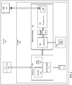
FIG. 1 is a block diagram of an aircraft controller including a multi-core processor and having capability to wirelessly exchange prognostic/diagnostic data to a prognostics and health monitoring (PHM) system according to a non-limiting embodiment; and -
FIG. 2 is a block diagram of an aircraft controller including a multi-core processor and having capability to wirelessly exchange prognostic/diagnostic data to a prognostics and health monitoring (PHM) system according to another non-limiting embodiment. - A detailed description of one or more embodiments of the disclosed apparatus and method are presented herein by way of exemplification and not limitation with reference to the Figures.
- The term "about" is intended to include the degree of error associated with measurement of the particular quantity based upon the equipment available at the time of filing the application.
- As used herein, the term "module" refers to an application specific integrated circuit (ASIC), an electronic circuit, a microprocessor, a computer processor (shared, dedicated, or group) and memory that executes one or more software or firmware programs, a combinational logic circuit, a microcontroller including various inputs and outputs, and/or other suitable components that provide the described functionality. The module is configured to execute various algorithms, transforms, and/or logical processes to generate one or more signals of controlling a component or system. When implemented in software, a module can be embodied in memory as a non-transitory machine-readable storage medium readable by a processing circuit (e.g., a microprocessor) and storing instructions for execution by the processing circuit for performing a method. A controller refers to an electronic hardware controller including a storage unit capable of storing algorithms, logic or computer executable instruction, and that contains the circuitry necessary to interpret and execute instructions.
- Turning now to a description of technologies that are more relevant to the present teachings, an aircraft may employ several different LRUs capable of recording operating data and/or fault data of one or more aircraft systems during flight operation. The operating data and/or fault data is typically stored in non-volatile memory (NVM), which can later be retrieved by a service technician. However, the complex housing designs and mounting arrangements of a given LRU make it difficult to obtain the recorded data from the NVM. LRUs are known to include Ethernet ports, which allow data to be downloaded from the NVM. The Ethernet ports, however, are typically encased by the LRU cover and removing the LRU cover to access the Ethernet ports exposes the internal components to a risk of foreign object damage. As a result, the alternative solution to retrieving the recorded operating data is to physically remove the LRU from the aircraft and access the Ethernet ports in a safe and controlled environment, which many times is located offsite from the location of the aircraft.
- Various non-limiting embodiments described herein provide an aircraft controller that includes a multi-core processor. The aircraft controller has the capability to wirelessly exchange prognostic/diagnostic data to a prognostics and health monitoring (PHM) system. The multi-core processor includes a lower-level priority prognostic core that is partitioned from a high-level priority control core. The partitioning allows the prognostic core to operate without interrupting operation of the high-level control core. In this manner, the prognostic core can obtain operating data and/or fault data during the flight of the aircraft, process the obtained operating/fault data to generate prognostic and diagnostic data, and transmit the prognostic and diagnostic data during flight to a PHM system installed on the aircraft. Accordingly, the prognostic and diagnostic data is easily obtained during the flight of the aircraft without exposing the internal components of the LRU to foreign object damage, and/or without the need to physically remove the LRU once the aircraft is grounded.
- With reference now to
FIG. 1 , amotor controller 100 installed on anaircraft 102 is illustrated according to a non-limiting embodiment. Themotor controller 100 includes amain processor 104 in signal communication with amulti-core processor 106. - The
main processor 104 is in signal communication with anaircraft communication system 108 to receive operational commands from the aircraft system. The operation commands include, but are not limited to, motor control commands, software download enable commands, power commands. Electrical operational information such as, for example voltages, current, speed/frequency, protection status from theelectrical system 121 can be returned to theaircraft system 102. - The
main processor 104 includes aprotection unit 110, amode unit 112, and acommunications unit 114. Any one of theprotection unit 110,mode unit 112, andcommunications unit 114 can be constructed as an electronic hardware controller that includes memory and a processor configured to execute algorithms and computer-readable program instructions stored in the memory. - The
protection unit 110 is configured to employ various protection measures. The protection measures aim to protect various systems of the aircraft including, but not limited motor system, power generation systems, power distribution system, and motor controller LRUs. Some examples would be over/under/unbalanced current protection, over/under voltage protection, over/under speed protection, over frequency protection, and over temperature protection. The protection operation can include, for example, disconnecting components or shutting down sub-systems when an over/under protection event is detected. - The
mode unit 112 is configured to invoke different modes of theelectrical system 121. In the example of a motor system, themode unit 112 can invoke different operating modes of one ormore motors 122. In some instances, different motors may operate according to different operational logic and protections. For example, themode controller 112 can invoke one mode to operate a permanent magnet motor, and another mode to operate an induction motor. - The
communications unit 114 is configured to facilitate inter-processor communication on theaircraft 102. In at least one embodiment, thecommunications unit 114 can facilitate data exchange between theaircraft 102 and the multi-core processor, - The
multi-core motor processor 106 includes one ormore control cores 116, one ormore prognostics cores 118, and one or more sharedmemory units 120. Thecontrol core 116 is in signal communication with anelectrical system 121 to control power delivered thereto. Theelectrical system 121 includes, but is not limited to, a motor system including one ormore motors 122, a power generator system, and a power distribution system. Thecontrol core 116 and theprognostic core 118 can each be constructed as an independent processing unit referred to as "a core", which is capable of reading and executing program instructions. The program instructions include various central processing unit (CPU) instructions including, but not limited to, add instructions, data move instructions, and branch instructions. - The
control core 116 generates controls signals that control operation of a power inverter circuit (not shown), for example, which drives amotor 122. Although onemotor 122 is illustrated, thecontrol core 116 and/or power inverter circuit can drive several different motors. Thecontrol core 116 can performs the actual control of different motors based on current, voltage, or speed and receives run, stop, and/or protection commands from themain processor 104. In at least one embodiment, the control core(s) 116 and its operations can be assigned a higher priority level than the prognostic core(s) 118. - The
prognostics core 118 is configured to generate prognostics and diagnostics data of theelectrical system 121, e.g., themotor 122. In one or more embodiments, the electrical system operating data includes, for example, voltage data, current data, load data, torque data, temperature data, and frequency data. Data can be passed from themain processor 104 to theprognostics core 118. Data can also be passed from thecontrol core 116 to theprognostics core 118. Theprognostics core 118 is configured to process the obtained data into prognostics and diagnostics data, which has format that can be used by a health management system (not shown). - In at least one embodiment, a non-volatile memory (NVM)
unit 111 is provided to store operating data and/or fault data obtained by themain processor 104. In one or more embodiments, theprognostics core 118 is configured to access theNVM 111 directly to obtain the operating data and/or fault data. In other embodiments, theprognostics core 118 can output an NVM data request to themain processor 104. In response to receiving the NVM data request, themain processor 104 can obtain the operating data and/or fault data from theNVM unit 111, and deliver the operating data and/or fault data directly toprognostics core 118. In either case, theprognostic core 118 can then transmit the operating data and/or fault data wirelessly to thePHM 202. - In one or more embodiments, each
prognostics core 118 is partitioned (i.e., in space and time) from the control core(s) 116. The partitioning refers to partitioning theprognostics core 118 in space and time from thecontrol core 116. In other words, theprognostics core 118 is partitioned in space such that no other partition can change this partition's memory or affect its allocated time to execute. Accordingly, a separate additional power supply in not required to power the prognostic core(s) 118 thereby avoiding introduction of failure points and power signal noise into the prognostic/diagnostic data signals. The partition also prevents any unintended interactions with the motor control software installed thecontrol core 116. Accordingly, theprognostic core 118 can operate while the aircraft is in-flight to obtain motor operational data and perform prognostic/diagnostic processing and analysis without seizing any cycles from the control core or interrupting the higher priority processing operations (e.g., motor control operations) of thecontrol core 116. For example, theprognostics core 118 will be prevented from operating themotor 122, while thecontrol core 116 can operate entirely independent of theprognostics core 118. In at least one embodiment, thecontrol core 116 is also capable of enabling/disabling theprognostics core 118, while theprognostics core 118 is prevented from interrupting thecontrol core 116 and/or themain processor operation 104 - The shared
memory unit 120 is in signal communication with both thecontrol core 116 and theprognostics core 118. In one or more embodiments, thecontrol core 116 is configured to obtain operating data during operation of themotor 122 and store the operating data in the sharedmemory unit 120. Theprognostics core 118 is configured to obtain the operating data from the sharedmemory unit 120, and process and analyze the operating data to perform maintenance and health predictions of themotor 122. In some embodiments, the sharedmemory unit 120 can be installed externally from both thecontrol core 116 and theprognostics core 118 as illustrated inFIG. 1 . In other embodiments, the sharedmemory unit 120 can be integrated in thecontrol core 116, while still allowing data access to theprognostics core 118. In some embodiments, a plurality of sharedmemory units 120 can be employed when a plurality ofcontrol cores 116 are included in themulti-core processor 106. In this scenario, some sharedmemory units 120 can be integrated in somecontrol cores 116, while other sharedmemory units 120 are installed externally from both thecontrol core 116 and theprognostics core 118. - In one or more embodiments described herein, the
prognostics core 118 is in signal communication with awireless device 200 configured to wirelessly exchange data with a prognostics and health monitoring (PHM)system 202 installed on theaircraft 102. Still referring toFIG. 1 , thewireless device 200 establishes signal communication with theprognostics core 118 via awired interface 204. Unlike conventional Ethernet ports which are encased and not accessible without removing the LRU cover (e.g., the cover to controller 100), thewired interface 204 is accessible without requiring removal of the outer cover such that internal components can be protected from foreign object damage. - The
wired interface 204 includes, for example, a Universal Serial Bus (USB)interface 204. Accordingly, thewireless device 200 can include a USB connector, which can be connected and disconnected to theinterface 204 without removing the controller cover. The operating data and/or fault data from theprognostics core 118 can then be delivered to thewireless device 200, which in turn wirelessly transmits the operating data and/or fault data to thePHM system 202 while the aircraft is in-flight. In this manner, the operating data and/or fault data can be obtained without exposing the internal components of thecontroller 106 to foreign object damage and/or without requiring physical removal of thecontroller 106. - The
PHM system 202 processes, organizes, and stores the operating data and/or fault data received from theprognostics core 118. Once the aircraft is grounded, thePHM system 202 can wirelessly transmit the stored data to a data processing and analytics system (not shown). The data processing and analytics system can perform advanced analytics such as, for example, artificial intelligence (AI) analysis on the operating data and/or fault data to perform fault diagnosis, root cause predictions, future fault predictions, and resolution measures. - Turning to
FIG. 2 , anaircraft controller 100 including amulti-core processor 106 having capability to wirelessly exchange prognostic/diagnostic data to the prognostics and healthmonitoring PHM system 202 according to another non-limiting embodiment. Rather than employ a wireless interface 204 (seeFIG. 1 ) with theprognostics core 118 to facilitate wireless communication with thePHM system 202, thewireless device 200 is integrated with theprognostic core 118. In one example, thewireless device 200 can be constructed as an integrated chip (IC) that is coupled directly to the prognostic core circuit board. Accordingly, the operating data and/or fault data from theprognostics core 118 can then be output to thewireless device 200, which in turn wirelessly transmits the operating data and/or fault data to thePHM system 202 while the aircraft is in-flight. In this manner, the operating data and/or fault data can be obtained without exposing the internal components of thecontroller 106 to foreign object damage and/or without requiring physical removal of thecontroller 106. - As described herein, various embodiments provide a multi-core processor that includes one or more control cores capable of high-priority power control such as, for example, power inversion and motor control, while a separately partitioned prognostics core performs lower-priority prognostic/diagnostic data processing and analysis. The partitioning of the prognostics core prevents any unintended interactions with the control core software, and also avoids cycle usage and interruption of the control core, thereby allowing the prognostics core to operate while the aircraft is operating in-flight.
- The terminology used herein is for the purpose of describing particular embodiments only and is not intended to be limiting of the present disclosure. As used herein, the singular forms "a", "an" and "the" are intended to include the plural forms as well, unless the context clearly indicates otherwise. It will be further understood that the terms "comprises" and/or "comprising," when used in this specification, specify the presence of stated features, integers, steps, operations, elements, and/or components, but do not preclude the presence or addition of one or more other features, integers, steps, operations, element components, and/or groups thereof.
- While the present disclosure has been described with reference to an exemplary embodiment or embodiments, it will be understood by those skilled in the art that various changes may be made and equivalents may be substituted for elements thereof without departing from the scope of the invention as defined by the claims. In addition, many modifications may be made to adapt a particular situation or material to the teachings of the present disclosure without departing from the scope of the invention. Therefore, it is intended that the present disclosure not be limited to the particular embodiment disclosed as the best mode contemplated for carrying out this present disclosure, but that the present disclosure will include all embodiments falling within the scope of the claims.
Claims (15)
- An aircraft comprising:an electrical system (121) installed on the aircraft;an electronic controller (100) in signal communication with the electrical system, the electronic controller including a main processor (104) and a multi-core processor (106), the multi-core processor including at least one control core (116) in signal communication with the electrical system to control power delivered thereto, and at least one prognostics core (118) configured to process and analyze prognostics and diagnostics data of the electrical system independently from operation of the control core;a wireless device (200) in signal communication with the at least one prognostics core to receive the prognostics and diagnostics data therefrom; anda prognostics and health monitoring, PHM, system (202) located remotely from the electronic controller, the PHM system configured to wirelessly receive the prognostics and diagnostics data.
- The aircraft of claim 1, wherein the at least one prognostics core (118) includes a wired interface (204) configured to establish a wired connection between the wireless device and the at least one prognostics core.
- The aircraft of claim 2, wherein the wireless device is located externally from the electronic controller, and includes a wired connector configured to facilitate and connection and disconnection with the at least one prognostics core.
- The aircraft of claim 1, wherein the wired device is integrated with the at least one prognostics core.
- The aircraft of claim 1, wherein the at least one prognostics core is partitioned from the at least one control core and performs processing and analysis of the prognostics and diagnostics data without using processing cycles of the control core.
- The aircraft of claim 5, wherein the electronic controller further includes a shared memory unit (120) in signal communication with the at least one control core and the at least one prognostics core.
- The aircraft of claim 6, wherein the at least one control core is configured to store operating data obtained during operation of the electrical system in the shared memory unit, and the at least one prognostics core is configured to obtain the operating data from the shared memory unit, and process and analyze the operating data to perform maintenance and health predictions of the electrical system.
- The aircraft of any preceding claim, wherein the at least one prognostics core (118) performs the processing and analysis of the prognostics and diagnostics data during in-flight operation of the aircraft.
- The aircraft of any preceding claim, wherein the electrical system is a motor system including at least one motor (122).
- The aircraft of any preceding claim, wherein the electrical system includes at least one of a power distribution system and a power generator system.
- An electronic aircraft controller configured to control an electrical system of an aircraft, the aircraft controller comprising:
a multicore processor (106) comprising:at least one control core (116) configured to generate a power control signal to control the electrical system;at least one prognostics core (118) configured to process and analyze prognostics and diagnostics data of the electrical system independently from operation of the control core,wherein the at least one prognostics core is configured to deliver the prognostics and diagnostics data to a wireless device that is configured to wirelessly transmit the prognostics and diagnostics data to a prognostics and health monitoring, PHM, system (202) installed on the aircraft and located remotely from the aircraft controller. - The aircraft controller of claim 11, wherein the at least one prognostics core includes a wired interface (204) configured to establish a wired connection between the wireless device and the at least one prognostics core, and to facilitate connection and disconnection between the at least one prognostics core and the wired device.
- The aircraft controller of claim 11, wherein the wired device is integrated with the at least one prognostics core.
- The aircraft controller of claim 11, wherein the at least one prognostics core is partitioned from the at least one control core and performs processing and analysis of the prognostics and diagnostics data without using processing cycles of the control core, and wherein the at least one prognostics core performs the processing and analysis of the prognostics and diagnostics data during in-flight operation of the aircraft
- A method of controlling an electrical system installed in an aircraft, the method comprising:outputting, via at least one control core included in a multi-core processor, power signals to operate the electrical system;returning operating data from the electrical system to the at least one control core;processing, via a prognostics core included in the multi-core processor, the operating data independently from operation of the control core;generating prognostics and diagnostics data of the electrical system based on the operating data independently from operation of the control core;outputting the prognostics and diagnostics data from the prognostics core to a wireless device; andwirelessly transmitting the prognostics and diagnostics data from the wireless device to a prognostics and health monitoring (PHM) system installed on the aircraft and located remotely from the aircraft controller.
Applications Claiming Priority (1)
| Application Number | Priority Date | Filing Date | Title |
|---|---|---|---|
| US16/204,378 US11254441B2 (en) | 2018-11-29 | 2018-11-29 | Aircraft controller including multiple core processor with wireless transmission prognostic/diagnostic data capability |
Publications (2)
| Publication Number | Publication Date |
|---|---|
| EP3660605A1 true EP3660605A1 (en) | 2020-06-03 |
| EP3660605B1 EP3660605B1 (en) | 2023-03-29 |
Family
ID=68581305
Family Applications (1)
| Application Number | Title | Priority Date | Filing Date |
|---|---|---|---|
| EP19208675.9A Active EP3660605B1 (en) | 2018-11-29 | 2019-11-12 | Aircraft controller including multiple core processor with wireless transmission prognostic/diagnostic data capability |
Country Status (2)
| Country | Link |
|---|---|
| US (1) | US11254441B2 (en) |
| EP (1) | EP3660605B1 (en) |
Cited By (1)
| Publication number | Priority date | Publication date | Assignee | Title |
|---|---|---|---|---|
| EP3660604A1 (en) * | 2018-11-30 | 2020-06-03 | Hamilton Sundstrand Corporation | Multiple core motor controller processor with embedded prognostic/diagnostic capabilities |
Families Citing this family (6)
| Publication number | Priority date | Publication date | Assignee | Title |
|---|---|---|---|---|
| CN112712304A (en) * | 2021-03-29 | 2021-04-27 | 北京星际荣耀空间科技股份有限公司 | Spacecraft prediction and health management system evaluation system |
| US20220363404A1 (en) * | 2021-05-14 | 2022-11-17 | Beta Air, Llc | Systems and methods for monitoring health of an electric vertical take-off and landing vehicle |
| CN113955131A (en) * | 2021-12-21 | 2022-01-21 | 山东欧龙电子科技有限公司 | Data intelligent monitoring processing platform for health state of manned aircraft |
| CN115598999B (en) * | 2022-12-14 | 2023-04-07 | 中国航空工业集团公司西安飞机设计研究所 | A method and device for verifying the fault diagnosis function of an airborne PHM system |
| US20250250025A1 (en) * | 2024-02-01 | 2025-08-07 | Hamilton Sundstrand Corporation | Smart iot controller for gathering and transmitting aircraft health information during flight |
| US20250361024A1 (en) * | 2024-05-23 | 2025-11-27 | Rosemount Aerospace Inc. | PROGNOSTIC HEALTH MONITOR FOR AIRCRAFT-BASED ANALOG ANGLE OF ATTACK (AoA) SENSORS |
Citations (3)
| Publication number | Priority date | Publication date | Assignee | Title |
|---|---|---|---|---|
| US8301867B1 (en) * | 2009-08-10 | 2012-10-30 | Rockwell Collins, Inc. | Secondary core ONU to OLT via internal EPON bus coupled multi-core processor for integrated modular avionic system |
| DE102014019531A1 (en) * | 2014-12-23 | 2016-06-23 | Liebherr-Aerospace Lindenberg Gmbh | Method for operating an aircraft control component and control component |
| US20170147008A1 (en) * | 2013-11-26 | 2017-05-25 | Airbus Operations (Sas) | Flight management system of an aircraft |
Family Cites Families (32)
| Publication number | Priority date | Publication date | Assignee | Title |
|---|---|---|---|---|
| US20080161989A1 (en) * | 1995-06-07 | 2008-07-03 | Automotive Technologies International, Inc. | Vehicle Diagnostic or Prognostic Message Transmission Systems and Methods |
| US9443358B2 (en) * | 1995-06-07 | 2016-09-13 | Automotive Vehicular Sciences LLC | Vehicle software upgrade techniques |
| US7797062B2 (en) * | 2001-08-10 | 2010-09-14 | Rockwell Automation Technologies, Inc. | System and method for dynamic multi-objective optimization of machine selection, integration and utilization |
| US8914300B2 (en) * | 2001-08-10 | 2014-12-16 | Rockwell Automation Technologies, Inc. | System and method for dynamic multi-objective optimization of machine selection, integration and utilization |
| US9729639B2 (en) * | 2001-08-10 | 2017-08-08 | Rockwell Automation Technologies, Inc. | System and method for dynamic multi-objective optimization of machine selection, integration and utilization |
| US6943699B2 (en) * | 2003-07-23 | 2005-09-13 | Harris Corporation | Wireless engine monitoring system |
| US20080147571A1 (en) * | 2006-09-29 | 2008-06-19 | Caterpillar Inc. | System and method for analyzing machine customization costs |
| US20080177436A1 (en) * | 2006-11-22 | 2008-07-24 | Fortson Frederick O | Diagnostic and telematic system |
| US20090027229A1 (en) * | 2007-07-11 | 2009-01-29 | Fortson Frederick O | Smart armor |
| US8229622B2 (en) | 2008-01-30 | 2012-07-24 | Honeywell International Inc. | Data recorder and storage system for line replaceable unit |
| US8396622B2 (en) * | 2008-04-23 | 2013-03-12 | Service Solutions U.S. Llc | Customizable initiation of data recordings |
| US9193313B2 (en) * | 2012-03-22 | 2015-11-24 | Nuax, Inc. | Methods and apparatuses involving flexible cable/guidewire/interconnects |
| US8036847B2 (en) * | 2008-09-25 | 2011-10-11 | Rockwell Automation Technologies, Inc. | Maximum information capture from energy constrained sensor nodes |
| US8493906B1 (en) * | 2009-09-11 | 2013-07-23 | Rockwell Collins, Inc. | Wireless aircraft gateway with auxiliary battery power |
| US7966437B1 (en) | 2009-09-18 | 2011-06-21 | Rockwell Collins, Inc. | Wireless USB enabled dataloads |
| US8909981B2 (en) * | 2011-06-21 | 2014-12-09 | Hamilton Sundstrand Corporation | Control system software execution during fault detection |
| US9481473B2 (en) * | 2013-03-15 | 2016-11-01 | Rolls-Royce North American Technologies, Inc. | Distributed control system with smart actuators and sensors |
| EP3201845A4 (en) * | 2014-09-29 | 2018-05-30 | Sikorsky Aircraft Corporation | Vibration signatures for prognostics and health monitoring of machinery |
| US9507982B2 (en) * | 2015-01-06 | 2016-11-29 | Honeywell International Inc. | Line replaceable unit health nodes and methods for determining maintenance actions relating to line replaceable units |
| US9440749B1 (en) * | 2015-03-05 | 2016-09-13 | Comac America Corporation | Emergency mechanical and communication systems and methods for aircraft |
| US9607452B2 (en) * | 2015-04-21 | 2017-03-28 | United Technologies Corporation | Electronic module integration for harsh environment machines |
| WO2017116655A1 (en) * | 2015-12-28 | 2017-07-06 | Cooper Technologies Company | Prognostic and health monitoring systems for circuit breakers |
| CA3009773C (en) * | 2015-12-28 | 2023-09-05 | Eaton Intelligent Power Limited | Prognostic and health monitoring systems for light fixtures |
| US10035609B2 (en) * | 2016-03-08 | 2018-07-31 | Harris Corporation | Wireless engine monitoring system for environmental emission control and aircraft networking |
| US10587635B2 (en) * | 2017-03-31 | 2020-03-10 | The Boeing Company | On-board networked anomaly detection (ONAD) modules |
| EP3652721A1 (en) * | 2017-09-04 | 2020-05-20 | NNG Software Developing and Commercial LLC | A method and apparatus for collecting and using sensor data from a vehicle |
| US10426393B2 (en) * | 2017-09-22 | 2019-10-01 | Aurora Flight Sciences Corporation | Systems and methods for monitoring pilot health |
| US10867455B2 (en) * | 2017-10-20 | 2020-12-15 | Appliedea, Inc. | Diagnostics, prognostics, and health management for vehicles using kinematic clusters, behavioral sensor data, and maintenance impact data |
| US10544738B2 (en) * | 2017-10-30 | 2020-01-28 | Honeywell International Inc. | Energy scavenging health monitors for aircraft and other vehicles |
| US10451139B2 (en) * | 2017-11-30 | 2019-10-22 | Honeywell International Inc. | Damping coefficient-regulating inductive heating systems and isolator assemblies including the same |
| US10965794B2 (en) * | 2018-08-02 | 2021-03-30 | Gogo Business Aviation Llc | On-board self-healing network for delivery of vehicle passenger-consumable content |
| US11300069B2 (en) * | 2018-11-28 | 2022-04-12 | Honeywell International Inc. | Self-generating engine-specific health monitoring model from generic model base |
-
2018
- 2018-11-29 US US16/204,378 patent/US11254441B2/en active Active
-
2019
- 2019-11-12 EP EP19208675.9A patent/EP3660605B1/en active Active
Patent Citations (3)
| Publication number | Priority date | Publication date | Assignee | Title |
|---|---|---|---|---|
| US8301867B1 (en) * | 2009-08-10 | 2012-10-30 | Rockwell Collins, Inc. | Secondary core ONU to OLT via internal EPON bus coupled multi-core processor for integrated modular avionic system |
| US20170147008A1 (en) * | 2013-11-26 | 2017-05-25 | Airbus Operations (Sas) | Flight management system of an aircraft |
| DE102014019531A1 (en) * | 2014-12-23 | 2016-06-23 | Liebherr-Aerospace Lindenberg Gmbh | Method for operating an aircraft control component and control component |
Non-Patent Citations (1)
| Title |
|---|
| CHRISTIAN EL SALLOUM ET AL: "The ACROSS MPSoC -- A New Generation of Multi-core Processors Designed for Safety-Critical Embedded Systems", DIGITAL SYSTEM DESIGN (DSD), 2012 15TH EUROMICRO CONFERENCE ON, IEEE, 5 September 2012 (2012-09-05), pages 105 - 113, XP032293712, ISBN: 978-1-4673-2498-4, DOI: 10.1109/DSD.2012.126 * |
Cited By (1)
| Publication number | Priority date | Publication date | Assignee | Title |
|---|---|---|---|---|
| EP3660604A1 (en) * | 2018-11-30 | 2020-06-03 | Hamilton Sundstrand Corporation | Multiple core motor controller processor with embedded prognostic/diagnostic capabilities |
Also Published As
| Publication number | Publication date |
|---|---|
| EP3660605B1 (en) | 2023-03-29 |
| US11254441B2 (en) | 2022-02-22 |
| US20200172261A1 (en) | 2020-06-04 |
Similar Documents
| Publication | Publication Date | Title |
|---|---|---|
| EP3660605B1 (en) | Aircraft controller including multiple core processor with wireless transmission prognostic/diagnostic data capability | |
| US10374894B2 (en) | Uninterruptable verification and control upgrade for real-time control system | |
| US8285402B2 (en) | Method and system for safety monitored terminal block | |
| EP2413484A2 (en) | Safety control system | |
| US8116940B2 (en) | Systems and method for collecting data in a vehicle | |
| EP3076293A2 (en) | Control apparatus | |
| EP3726689B1 (en) | Integration of aircraft management system and power distribution control | |
| CN104182017A (en) | Intelligent heat radiation control system and method for server | |
| US20150012683A1 (en) | Devices, Systems, and Methods for Distributed Monitoring and Control of Networked Server Computers | |
| US9068880B2 (en) | Accommodation of different type of sensors in vibration monitoring system using external input or daughter board with interchangeable operating hardware | |
| US20190056970A1 (en) | Method for computer-aided coupling a processing module into a modular technical system and modular technical system | |
| US11358473B2 (en) | Vehicle management system and parallel power distribution lines | |
| EP3660604A1 (en) | Multiple core motor controller processor with embedded prognostic/diagnostic capabilities | |
| JP6230092B2 (en) | Monitoring system | |
| US11340561B2 (en) | Control system, support device, and storage medium | |
| US20140214181A1 (en) | Control system for software termination protection | |
| EP3859454B1 (en) | Control system | |
| CN105468495B (en) | Complicated formula can procedure logical control system device | |
| KR20140066357A (en) | Method for updating firmware of multiple micro controller unit and electronic control unit using the same | |
| AU2016102332A4 (en) | Traffic Signal Control System with Multiple Control Nodes | |
| JP7544994B2 (en) | Electronic control device, fault diagnosis system, and fault diagnosis method | |
| CN108138946B (en) | Diagnosis of control equipment | |
| CN117789805B (en) | Signal monitoring method and device, chip and electronic equipment | |
| CN114857069B (en) | Fan jig plate | |
| CN102189995A (en) | Method for stopping functional unit operated by controller in motor vehicle |
Legal Events
| Date | Code | Title | Description |
|---|---|---|---|
| PUAI | Public reference made under article 153(3) epc to a published international application that has entered the european phase |
Free format text: ORIGINAL CODE: 0009012 |
|
| STAA | Information on the status of an ep patent application or granted ep patent |
Free format text: STATUS: THE APPLICATION HAS BEEN PUBLISHED |
|
| AK | Designated contracting states |
Kind code of ref document: A1 Designated state(s): AL AT BE BG CH CY CZ DE DK EE ES FI FR GB GR HR HU IE IS IT LI LT LU LV MC MK MT NL NO PL PT RO RS SE SI SK SM TR |
|
| AX | Request for extension of the european patent |
Extension state: BA ME |
|
| STAA | Information on the status of an ep patent application or granted ep patent |
Free format text: STATUS: REQUEST FOR EXAMINATION WAS MADE |
|
| 17P | Request for examination filed |
Effective date: 20201203 |
|
| RBV | Designated contracting states (corrected) |
Designated state(s): AL AT BE BG CH CY CZ DE DK EE ES FI FR GB GR HR HU IE IS IT LI LT LU LV MC MK MT NL NO PL PT RO RS SE SI SK SM TR |
|
| GRAP | Despatch of communication of intention to grant a patent |
Free format text: ORIGINAL CODE: EPIDOSNIGR1 |
|
| STAA | Information on the status of an ep patent application or granted ep patent |
Free format text: STATUS: GRANT OF PATENT IS INTENDED |
|
| INTG | Intention to grant announced |
Effective date: 20221103 |
|
| GRAS | Grant fee paid |
Free format text: ORIGINAL CODE: EPIDOSNIGR3 |
|
| GRAA | (expected) grant |
Free format text: ORIGINAL CODE: 0009210 |
|
| STAA | Information on the status of an ep patent application or granted ep patent |
Free format text: STATUS: THE PATENT HAS BEEN GRANTED |
|
| AK | Designated contracting states |
Kind code of ref document: B1 Designated state(s): AL AT BE BG CH CY CZ DE DK EE ES FI FR GB GR HR HU IE IS IT LI LT LU LV MC MK MT NL NO PL PT RO RS SE SI SK SM TR |
|
| REG | Reference to a national code |
Ref country code: CH Ref legal event code: EP |
|
| REG | Reference to a national code |
Ref country code: DE Ref legal event code: R096 Ref document number: 602019026844 Country of ref document: DE |
|
| REG | Reference to a national code |
Ref country code: AT Ref legal event code: REF Ref document number: 1557122 Country of ref document: AT Kind code of ref document: T Effective date: 20230415 |
|
| REG | Reference to a national code |
Ref country code: IE Ref legal event code: FG4D |
|
| REG | Reference to a national code |
Ref country code: LT Ref legal event code: MG9D |
|
| P01 | Opt-out of the competence of the unified patent court (upc) registered |
Effective date: 20230603 |
|
| PG25 | Lapsed in a contracting state [announced via postgrant information from national office to epo] |
Ref country code: RS Free format text: LAPSE BECAUSE OF FAILURE TO SUBMIT A TRANSLATION OF THE DESCRIPTION OR TO PAY THE FEE WITHIN THE PRESCRIBED TIME-LIMIT Effective date: 20230329 Ref country code: NO Free format text: LAPSE BECAUSE OF FAILURE TO SUBMIT A TRANSLATION OF THE DESCRIPTION OR TO PAY THE FEE WITHIN THE PRESCRIBED TIME-LIMIT Effective date: 20230629 Ref country code: LV Free format text: LAPSE BECAUSE OF FAILURE TO SUBMIT A TRANSLATION OF THE DESCRIPTION OR TO PAY THE FEE WITHIN THE PRESCRIBED TIME-LIMIT Effective date: 20230329 Ref country code: LT Free format text: LAPSE BECAUSE OF FAILURE TO SUBMIT A TRANSLATION OF THE DESCRIPTION OR TO PAY THE FEE WITHIN THE PRESCRIBED TIME-LIMIT Effective date: 20230329 Ref country code: HR Free format text: LAPSE BECAUSE OF FAILURE TO SUBMIT A TRANSLATION OF THE DESCRIPTION OR TO PAY THE FEE WITHIN THE PRESCRIBED TIME-LIMIT Effective date: 20230329 |
|
| REG | Reference to a national code |
Ref country code: NL Ref legal event code: MP Effective date: 20230329 |
|
| REG | Reference to a national code |
Ref country code: AT Ref legal event code: MK05 Ref document number: 1557122 Country of ref document: AT Kind code of ref document: T Effective date: 20230329 |
|
| PG25 | Lapsed in a contracting state [announced via postgrant information from national office to epo] |
Ref country code: SE Free format text: LAPSE BECAUSE OF FAILURE TO SUBMIT A TRANSLATION OF THE DESCRIPTION OR TO PAY THE FEE WITHIN THE PRESCRIBED TIME-LIMIT Effective date: 20230329 Ref country code: NL Free format text: LAPSE BECAUSE OF FAILURE TO SUBMIT A TRANSLATION OF THE DESCRIPTION OR TO PAY THE FEE WITHIN THE PRESCRIBED TIME-LIMIT Effective date: 20230329 Ref country code: GR Free format text: LAPSE BECAUSE OF FAILURE TO SUBMIT A TRANSLATION OF THE DESCRIPTION OR TO PAY THE FEE WITHIN THE PRESCRIBED TIME-LIMIT Effective date: 20230630 Ref country code: FI Free format text: LAPSE BECAUSE OF FAILURE TO SUBMIT A TRANSLATION OF THE DESCRIPTION OR TO PAY THE FEE WITHIN THE PRESCRIBED TIME-LIMIT Effective date: 20230329 |
|
| PG25 | Lapsed in a contracting state [announced via postgrant information from national office to epo] |
Ref country code: SM Free format text: LAPSE BECAUSE OF FAILURE TO SUBMIT A TRANSLATION OF THE DESCRIPTION OR TO PAY THE FEE WITHIN THE PRESCRIBED TIME-LIMIT Effective date: 20230329 Ref country code: RO Free format text: LAPSE BECAUSE OF FAILURE TO SUBMIT A TRANSLATION OF THE DESCRIPTION OR TO PAY THE FEE WITHIN THE PRESCRIBED TIME-LIMIT Effective date: 20230329 Ref country code: PT Free format text: LAPSE BECAUSE OF FAILURE TO SUBMIT A TRANSLATION OF THE DESCRIPTION OR TO PAY THE FEE WITHIN THE PRESCRIBED TIME-LIMIT Effective date: 20230731 Ref country code: ES Free format text: LAPSE BECAUSE OF FAILURE TO SUBMIT A TRANSLATION OF THE DESCRIPTION OR TO PAY THE FEE WITHIN THE PRESCRIBED TIME-LIMIT Effective date: 20230329 Ref country code: EE Free format text: LAPSE BECAUSE OF FAILURE TO SUBMIT A TRANSLATION OF THE DESCRIPTION OR TO PAY THE FEE WITHIN THE PRESCRIBED TIME-LIMIT Effective date: 20230329 Ref country code: AT Free format text: LAPSE BECAUSE OF FAILURE TO SUBMIT A TRANSLATION OF THE DESCRIPTION OR TO PAY THE FEE WITHIN THE PRESCRIBED TIME-LIMIT Effective date: 20230329 |
|
| PG25 | Lapsed in a contracting state [announced via postgrant information from national office to epo] |
Ref country code: SK Free format text: LAPSE BECAUSE OF FAILURE TO SUBMIT A TRANSLATION OF THE DESCRIPTION OR TO PAY THE FEE WITHIN THE PRESCRIBED TIME-LIMIT Effective date: 20230329 Ref country code: PL Free format text: LAPSE BECAUSE OF FAILURE TO SUBMIT A TRANSLATION OF THE DESCRIPTION OR TO PAY THE FEE WITHIN THE PRESCRIBED TIME-LIMIT Effective date: 20230329 Ref country code: IS Free format text: LAPSE BECAUSE OF FAILURE TO SUBMIT A TRANSLATION OF THE DESCRIPTION OR TO PAY THE FEE WITHIN THE PRESCRIBED TIME-LIMIT Effective date: 20230729 |
|
| REG | Reference to a national code |
Ref country code: DE Ref legal event code: R097 Ref document number: 602019026844 Country of ref document: DE |
|
| PG25 | Lapsed in a contracting state [announced via postgrant information from national office to epo] |
Ref country code: DK Free format text: LAPSE BECAUSE OF FAILURE TO SUBMIT A TRANSLATION OF THE DESCRIPTION OR TO PAY THE FEE WITHIN THE PRESCRIBED TIME-LIMIT Effective date: 20230329 Ref country code: CZ Free format text: LAPSE BECAUSE OF FAILURE TO SUBMIT A TRANSLATION OF THE DESCRIPTION OR TO PAY THE FEE WITHIN THE PRESCRIBED TIME-LIMIT Effective date: 20230329 |
|
| PLBE | No opposition filed within time limit |
Free format text: ORIGINAL CODE: 0009261 |
|
| STAA | Information on the status of an ep patent application or granted ep patent |
Free format text: STATUS: NO OPPOSITION FILED WITHIN TIME LIMIT |
|
| 26N | No opposition filed |
Effective date: 20240103 |
|
| PG25 | Lapsed in a contracting state [announced via postgrant information from national office to epo] |
Ref country code: SI Free format text: LAPSE BECAUSE OF FAILURE TO SUBMIT A TRANSLATION OF THE DESCRIPTION OR TO PAY THE FEE WITHIN THE PRESCRIBED TIME-LIMIT Effective date: 20230329 |
|
| PG25 | Lapsed in a contracting state [announced via postgrant information from national office to epo] |
Ref country code: SI Free format text: LAPSE BECAUSE OF FAILURE TO SUBMIT A TRANSLATION OF THE DESCRIPTION OR TO PAY THE FEE WITHIN THE PRESCRIBED TIME-LIMIT Effective date: 20230329 Ref country code: IT Free format text: LAPSE BECAUSE OF FAILURE TO SUBMIT A TRANSLATION OF THE DESCRIPTION OR TO PAY THE FEE WITHIN THE PRESCRIBED TIME-LIMIT Effective date: 20230329 |
|
| REG | Reference to a national code |
Ref country code: CH Ref legal event code: PL |
|
| PG25 | Lapsed in a contracting state [announced via postgrant information from national office to epo] |
Ref country code: MC Free format text: LAPSE BECAUSE OF FAILURE TO SUBMIT A TRANSLATION OF THE DESCRIPTION OR TO PAY THE FEE WITHIN THE PRESCRIBED TIME-LIMIT Effective date: 20230329 |
|
| PG25 | Lapsed in a contracting state [announced via postgrant information from national office to epo] |
Ref country code: LU Free format text: LAPSE BECAUSE OF NON-PAYMENT OF DUE FEES Effective date: 20231112 |
|
| PG25 | Lapsed in a contracting state [announced via postgrant information from national office to epo] |
Ref country code: CH Free format text: LAPSE BECAUSE OF NON-PAYMENT OF DUE FEES Effective date: 20231130 |
|
| PG25 | Lapsed in a contracting state [announced via postgrant information from national office to epo] |
Ref country code: MC Free format text: LAPSE BECAUSE OF FAILURE TO SUBMIT A TRANSLATION OF THE DESCRIPTION OR TO PAY THE FEE WITHIN THE PRESCRIBED TIME-LIMIT Effective date: 20230329 Ref country code: LU Free format text: LAPSE BECAUSE OF NON-PAYMENT OF DUE FEES Effective date: 20231112 Ref country code: CH Free format text: LAPSE BECAUSE OF NON-PAYMENT OF DUE FEES Effective date: 20231130 |
|
| REG | Reference to a national code |
Ref country code: BE Ref legal event code: MM Effective date: 20231130 |
|
| REG | Reference to a national code |
Ref country code: IE Ref legal event code: MM4A |
|
| PG25 | Lapsed in a contracting state [announced via postgrant information from national office to epo] |
Ref country code: IE Free format text: LAPSE BECAUSE OF NON-PAYMENT OF DUE FEES Effective date: 20231112 |
|
| PG25 | Lapsed in a contracting state [announced via postgrant information from national office to epo] |
Ref country code: BE Free format text: LAPSE BECAUSE OF NON-PAYMENT OF DUE FEES Effective date: 20231130 |
|
| PG25 | Lapsed in a contracting state [announced via postgrant information from national office to epo] |
Ref country code: IE Free format text: LAPSE BECAUSE OF NON-PAYMENT OF DUE FEES Effective date: 20231112 Ref country code: BE Free format text: LAPSE BECAUSE OF NON-PAYMENT OF DUE FEES Effective date: 20231130 |
|
| PG25 | Lapsed in a contracting state [announced via postgrant information from national office to epo] |
Ref country code: BG Free format text: LAPSE BECAUSE OF FAILURE TO SUBMIT A TRANSLATION OF THE DESCRIPTION OR TO PAY THE FEE WITHIN THE PRESCRIBED TIME-LIMIT Effective date: 20230329 |
|
| PG25 | Lapsed in a contracting state [announced via postgrant information from national office to epo] |
Ref country code: BG Free format text: LAPSE BECAUSE OF FAILURE TO SUBMIT A TRANSLATION OF THE DESCRIPTION OR TO PAY THE FEE WITHIN THE PRESCRIBED TIME-LIMIT Effective date: 20230329 |
|
| PG25 | Lapsed in a contracting state [announced via postgrant information from national office to epo] |
Ref country code: CY Free format text: LAPSE BECAUSE OF FAILURE TO SUBMIT A TRANSLATION OF THE DESCRIPTION OR TO PAY THE FEE WITHIN THE PRESCRIBED TIME-LIMIT; INVALID AB INITIO Effective date: 20191112 |
|
| PG25 | Lapsed in a contracting state [announced via postgrant information from national office to epo] |
Ref country code: HU Free format text: LAPSE BECAUSE OF FAILURE TO SUBMIT A TRANSLATION OF THE DESCRIPTION OR TO PAY THE FEE WITHIN THE PRESCRIBED TIME-LIMIT; INVALID AB INITIO Effective date: 20191112 |
|
| PG25 | Lapsed in a contracting state [announced via postgrant information from national office to epo] |
Ref country code: TR Free format text: LAPSE BECAUSE OF FAILURE TO SUBMIT A TRANSLATION OF THE DESCRIPTION OR TO PAY THE FEE WITHIN THE PRESCRIBED TIME-LIMIT Effective date: 20230329 |
|
| PGFP | Annual fee paid to national office [announced via postgrant information from national office to epo] |
Ref country code: DE Payment date: 20251022 Year of fee payment: 7 |
|
| PGFP | Annual fee paid to national office [announced via postgrant information from national office to epo] |
Ref country code: GB Payment date: 20251023 Year of fee payment: 7 |
|
| PGFP | Annual fee paid to national office [announced via postgrant information from national office to epo] |
Ref country code: FR Payment date: 20251023 Year of fee payment: 7 |