EP3660522A1 - Method for evaluating electromagnetic performace of permanent-magnet machines - Google Patents
Method for evaluating electromagnetic performace of permanent-magnet machines Download PDFInfo
- Publication number
- EP3660522A1 EP3660522A1 EP19211083.1A EP19211083A EP3660522A1 EP 3660522 A1 EP3660522 A1 EP 3660522A1 EP 19211083 A EP19211083 A EP 19211083A EP 3660522 A1 EP3660522 A1 EP 3660522A1
- Authority
- EP
- European Patent Office
- Prior art keywords
- slot
- sub
- domain
- current density
- stator
- Prior art date
- Legal status (The legal status is an assumption and is not a legal conclusion. Google has not performed a legal analysis and makes no representation as to the accuracy of the status listed.)
- Granted
Links
Images









Classifications
-
- G—PHYSICS
- G01—MEASURING; TESTING
- G01R—MEASURING ELECTRIC VARIABLES; MEASURING MAGNETIC VARIABLES
- G01R29/00—Arrangements for measuring or indicating electric quantities not covered by groups G01R19/00 - G01R27/00
- G01R29/08—Measuring electromagnetic field characteristics
- G01R29/0864—Measuring electromagnetic field characteristics characterised by constructional or functional features
-
- G—PHYSICS
- G01—MEASURING; TESTING
- G01R—MEASURING ELECTRIC VARIABLES; MEASURING MAGNETIC VARIABLES
- G01R31/00—Arrangements for testing electric properties; Arrangements for locating electric faults; Arrangements for electrical testing characterised by what is being tested not provided for elsewhere
- G01R31/34—Testing dynamo-electric machines
- G01R31/343—Testing dynamo-electric machines in operation
-
- G—PHYSICS
- G06—COMPUTING OR CALCULATING; COUNTING
- G06F—ELECTRIC DIGITAL DATA PROCESSING
- G06F30/00—Computer-aided design [CAD]
- G06F30/10—Geometric CAD
- G06F30/17—Mechanical parametric or variational design
-
- G—PHYSICS
- G06—COMPUTING OR CALCULATING; COUNTING
- G06F—ELECTRIC DIGITAL DATA PROCESSING
- G06F30/00—Computer-aided design [CAD]
- G06F30/20—Design optimisation, verification or simulation
-
- H—ELECTRICITY
- H02—GENERATION; CONVERSION OR DISTRIBUTION OF ELECTRIC POWER
- H02K—DYNAMO-ELECTRIC MACHINES
- H02K1/00—Details of the magnetic circuit
- H02K1/06—Details of the magnetic circuit characterised by the shape, form or construction
- H02K1/12—Stationary parts of the magnetic circuit
- H02K1/16—Stator cores with slots for windings
-
- H—ELECTRICITY
- H02—GENERATION; CONVERSION OR DISTRIBUTION OF ELECTRIC POWER
- H02K—DYNAMO-ELECTRIC MACHINES
- H02K1/00—Details of the magnetic circuit
- H02K1/06—Details of the magnetic circuit characterised by the shape, form or construction
- H02K1/22—Rotating parts of the magnetic circuit
- H02K1/27—Rotor cores with permanent magnets
-
- H—ELECTRICITY
- H02—GENERATION; CONVERSION OR DISTRIBUTION OF ELECTRIC POWER
- H02K—DYNAMO-ELECTRIC MACHINES
- H02K1/00—Details of the magnetic circuit
- H02K1/06—Details of the magnetic circuit characterised by the shape, form or construction
- H02K1/22—Rotating parts of the magnetic circuit
- H02K1/27—Rotor cores with permanent magnets
- H02K1/2706—Inner rotors
- H02K1/272—Inner rotors the magnetisation axis of the magnets being perpendicular to the rotor axis
- H02K1/274—Inner rotors the magnetisation axis of the magnets being perpendicular to the rotor axis the rotor consisting of two or more circumferentially positioned magnets
- H02K1/2753—Inner rotors the magnetisation axis of the magnets being perpendicular to the rotor axis the rotor consisting of two or more circumferentially positioned magnets the rotor consisting of magnets or groups of magnets arranged with alternating polarity
- H02K1/278—Surface mounted magnets; Inset magnets
-
- H—ELECTRICITY
- H02—GENERATION; CONVERSION OR DISTRIBUTION OF ELECTRIC POWER
- H02K—DYNAMO-ELECTRIC MACHINES
- H02K15/00—Processes or apparatus specially adapted for manufacturing, assembling, maintaining or repairing of dynamo-electric machines
- H02K15/02—Processes or apparatus specially adapted for manufacturing, assembling, maintaining or repairing of dynamo-electric machines of stator or rotor bodies
- H02K15/03—Processes or apparatus specially adapted for manufacturing, assembling, maintaining or repairing of dynamo-electric machines of stator or rotor bodies having permanent magnets
Definitions
- the present invention relates to the field of permanent magnet machine, and more particularly to methods for evaluating electromagnetic performance of electric machines in particular of permanent-magnet machine.
- Permanent magnet machines have received wide attention due to their high torque density, high power density and efficiency.
- Existing models are divided into numerical models, analytical models, magnetic circuit models, and composite models.
- the numerical models can be used to solve the machine with complicated structure and accurately calculate the core saturation effect, but usually the solving time is too long, resulting in a long design cycle; moreover, the performance cannot directly correspond to the machine dimension parameters, therefore, it is difficult for performance optimization.
- the analytical method is fast for solving, and the machine performance is directly related to the dimension parameters, therefore, it can provide optimization.
- the analytic method methods are divided into relative permeability method, complex permeability method, and sub-domain method.
- the analytical method can be used to solve the linear models only, that is, it is assumed that the machine stator and rotor yoke has infinite permeability, so the error will increase as the machine saturation increases.
- the nonlinearity of the core can be calculated by the Kirchoff's law and Newton-Raphson method; however, there are a large number of simplified processes in the magnetic circuit equivalent, which essentially discretizes a continuous field distribution, therefore, the magnetic field distribution cannot be accurately predicted.
- the present invention can accurately predict the tangential and radial magnetic field distribution in the permanent magnet body, the air gap and the stator slot by considering the nonlinearity of the machine core, and accurately calculate electromagnetic performance parameters such as the flux linkage of the machine, counter electromotive force, cogging torque, terminal voltage, total torque, imbalance force on the basis of the magnetic field distribution.
- a method for evaluating electromagnetic performance of a PM machine comprising: establishing an electromagnetic analytical model of the machine, the solution domain of the analytical model being at least divided into a permanent magnet sub-domain, an air gap sub-domain, and a stator slot sub-domain, and calculating the current magnetic field distributions of the air gap sub-domain, stator slot sub-domain and/or permanent magnet sub-domain based on a sub-domain method by the analytical model through a Poisson equation or a Laplace equation; adding an equivalent current sheet to the boundary of the target sub-domain and interface between the target sub-domain and a adjacent sub-domain respectively, representing the boundary condition and interface condition by the current density of the equivalent current sheet, and solving the magnetic field distribution by a sub-domain method; solving the magnetic potential difference of each part of the core by a magnetic circuit method according to the current magnetic field distribution, and converting the magnetic potential difference to a current density of the equivalent current sheet ; iterating the magnetic field distribution obtained by the sub-domain method and the current density obtained by the magnetic circuit method until a converge
- Each type of motor has its standard values of electromagnetic performance parameters.
- the electromagnetic performance of the motor is considered to meet the standard. If the difference exceeds the allowable error range, the electromagnetic performance of the motor is considered not to meet the standard.
- the method is executed on the computer processor. If the electromagnetic performance does not meet the standard, the design size of the motor needs to be modified until the electromagnetic performance of the motor meets the standard at the size. The method can be executed on a remote computer processor or a controller of the motor if the motor is in the running stage; and if the electromagnetic performance of the motor does not meet the standards, an early warning will be given.
- the stator slot sub-domain is the target sub-domain.
- electromagnetic performance parameters such as flux linkage, counter electromotive force, cogging torque, terminal voltage, load torque, unbalance force of the permanent magnet machine can be calculated according to the existing methods.
- the conventional sub-domain method assumes that both the stator and the rotor silicon steels have infinite permeability, so the saturation effect of the machine cannot be considered.
- the saturation effect is essentially the existence of a magnetic potential difference in the stator, and by using Ampere's law, the magnetic potential difference can be equivalent to the current density of the equivalent current sheets on the slot side and slot bottom; and after equivalence, the stator silicon steel permeability can be reconsidered as infinity.
- This current value can be solved by the magnetic circuit method and as the boundary condition of the slot region in the sub-domain method.
- the magnetic flux into the stator is calculated by the sub-domain method, as a magnetic flux source in the magnetic circuit method.
- the magnetic circuit method provides a current density of equivalent current sheet for the sub-domain method, with iteration relationship between them, when the current density of the current sheet converges, it is considered as the final saturation, at this time, the result calculated by the sub-domain method is the magnetic field distribution of the permanent magnet machine in consideration of the saturation, and the electromagnetic performance of the machine can be obtained based on the magnetic field distribution.
- the boundary condition when a vector magnetic potential expression of the stator slot sub-domain is established by the sub-domain method and the stator slot is an open slot, the boundary condition includes a boundary condition of the two slot sides and a boundary condition of the slot bottom, when calculating the vector magnetic potential expression of the permanent magnet sub-domain and the air gap sub-domain, the boundary condition is not changed; when the stator slot has a slot opening, the boundary condition includes the boundary condition of the two slot sides, the boundary condition of the slot bottom, and the boundary condition of the slot opening edge.
- the undetermined coefficients in each sub-domain expression is solved by simultaneous equations, when compiling a program, the equations set is written as a matrix, and there is matrix inversion process when the undetermined coefficients are solving, and after the undetermined coefficients are solved, the magnetic field distribution in each sub-domain is obtained.
- stator slot sub-domains For different stator slot types, the boundary conditions of stator slot sub-domains are different.
- the stator slots include open slots and semi-closed slots.
- the stator slot sub-domain includes the boundary condition of slot side and the boundary condition of slot bottom, and the boundary condition is represented by: H 3 ri
- the stator slot sub-domain includes the boundary condition of two slot sides and the boundary condition of the slot bottom, and the condition of two sides of the slot opening, and the boundary condition is represented by: H 3 ri
- b oa is the width of slot opening
- J i 1 the current density of the equivalent current sheet on the first slot side of the stator slot
- J i 2 is the current density of the equivalent current sheet on the second slot side of the stator slot
- J i 3 the current density of the equivalent current
- the boundary condition at the interface between the rotor yoke and the permanent magnet should also be considered.
- the range of the consequent-pole machine permanent magnet sub-domain is: ⁇ im - ⁇ mag / 2 ⁇ ⁇ ⁇ ⁇ im + ⁇ mag / 2; where, amag is the width angle of the permanent magnet, ⁇ im is the center line of the i-th permanent magnet, the consequent-pole rotor permanent magnet sub-domain is added with the boundary condition on the interface with the adjacent soft magnetic material, and the boundary condition is represented by the magnetic flux density: B rmi
- the consequent-pole rotor means that the rotor comprises a permanent magnet and a soft magnetic material, and the permanent magnet and the soft magnetic material are spaced apart, that is, a soft magnetic material is added between two adjacent permanent magnets.
- the permanent magnet sub-domain of the rotor is within the range of 0-2 ⁇ , and the permanent magnet sub-domain of the rotor is added with a boundary condition at the interface between the permanent magnet and the rotor yoke, the boundary condition is represented by the current density of an equivalent current sheet.
- the analytical model divides the solution domain on the 2D plane when the two-dimensional magnetic circuit is used as the target magnetic field of the analytical model.
- the silicon steel of stator core tooth portion and yoke portion is equivalent to different magnetic reluctance to construct a magnetic network, and the obtained current magnetic field distribution is converted into the magnetic flux into the stator as a magnetic flux source in the magnetic circuit method, to obtain the magnetic potential difference of each stator tooth and stator yoke by solving, the magnetic potential difference of the stator tooth and stator yoke is equivalent to the current density of equivalent current sheets on the slot side and slot bottom.
- the current magnetic field distribution comprises the magnetic field distribution of the sub-domain with which all the stator cores are in direct contact, including the air gap sub-domain in addition to the stator slot sub-domain; that is, the magnetic field distribution in the air gap and slot obtained by the current sub-domain method is converted to a magnetic flux into the stator.
- the magnetic circuit method there is a convergent solution for solving the node magnetic potential difference matrix by using the current magnetic field distribution cycle, indicating the magnetic field distribution of the stator core under the magnetic field distribution of the current sub-domain method and the convergent solution of the node magnetic potential difference matrix are equivalent to a current density.
- the convergence means that the difference of current density is less than an allowable error range.
- a magnetic network is established at the rotor yoke to calculate the current density of the equivalent current sheet between the rotor yoke and the rotor permanent magnet, and the current density is taken as the boundary condition at the interface between the rotor yoke and the rotor permanent magnet.
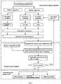
- the current density of the equivalent current sheet is preset to 0, and the sub-domain method is used to solve the magnetic field distribution for the first time, to obtain the magnetic flux into the stator; then the magnetic potential difference of each tooth portion and yoke portion of the stator is solved by the magnetic circuit method, and the current density value of corresponding equivalent current sheet is obtained by the magnetic potential difference; then current density value is used as a boundary condition of the sub-domain method to resolve; the above iterative process is repeated until the difference between the current density obtained in the previous iteration and the current density obtained in this iteration is within the preset threshold range.
- the mutual iteration between the magnetic circuit method and the sub-domain method is: the current density obtained by the convergent solution of the node magnetic potential difference matrix is taken into the sub-domain method as a boundary condition and/or an interface condition, to obtain the current magnetic field distribution by the sub-domain method, then calculate the status core magnetic field distribution to judge if the current density of this time and the current density of the previous time are converged; and if not, the current magnetic field distribution is taken into the magnetic circuit method, to solve the convergent solution of the node magnetic potential difference matrix again, and repeat the iterations until the current density of this time and the current density of the previous time are converged.
- a method for evaluating electromagnetic performance of a PM machine based on three-dimensional magnetic circuit comprising: establishing an analytical model by a three-dimensional magnetic circuit, wherein the three-dimensional magnetic circuit includes a plurality of sub-sheets divided by the non-ferromagnetic material in the axial direction, and the solution domain of each sub-sheet being at least divided into a permanent magnet sub-domain, an air gap sub-domain, and a stator slot sub-domain, and calculating the current magnetic field distributions of the air gap sub-domain, stator slot sub-domain and /or permanent magnet sub-domain based on a sub-domain method by the analytical model through a Poisson equation or a Laplace equation; adding an equivalent current sheet to the boundary of the target sub-domain and interface between the target sub-domain and a adjacent sub-domain respectively, representing the boundary condition and interface condition by the current density of the equivalent current sheet, and solving the magnetic field distribution by a sub-domain method; the magnetic field node of all the sub-sheet being arranged in the same position, the magnetic field node
- the solving of the sub-domain method is the same as the above two-dimensional magnetic field analytical model.
- a three-dimensional magnetic field is constructed by the magnetic circuit method.
- the solving of three-dimensional magnetic field includes the magnetic reluctance in each sub-sheet and the connected magnetic reluctance between adjacent sub-sheets, and the other solving is the same as that of the two-dimensional magnetic field analytical model. Because of different temperature distribution at the axial direction, the degree of nonlinearity is different, and the magnetic field distribution of each sub-sheet is different; therefore, the uneven distribution of the magnetic field in the axial direction can be calculated by the sub-sheets elaborately, and for complex and diverse machine structures, the oblique pole and stator core discontinuity can be calculated.
- the axial sub-sheets of the three-dimensional magnetic field are different in the nonlinear state of the stator core caused by the difference in temperature in the axial direction, that is, the BH curve of the stator core is different, so the part with similar nonlinearity (that is, the part that the same BH curve can be used) is used as a sub-sheet; or because of axially different structures, such as rotor block, oblique pole, stator slot discontinuity, etc., the part with the same axial section is used as a sub-sheet.
- each sub-sheet uses the respective BH curve to solve the magnetic reluctance of the current sheet; in the three-dimensional magnetic circuit, the stator core of each sub-sheet is equivalent to a two-dimensional magnetic circuit.
- the BH curve of the current sub-sheet is used to solve the magnetic reluctance in the sub-sheet.
- the same node position of the adjacent sub-sheets is connected by the connected magnetic reluctance, and the connected magnetic reluctance meter and the magnetic flux.
- the solution parameters of the entire three-dimensional magnetic circuit include the magnetic potential difference between the nodes in each sub-sheet and the magnetic potential difference between the same node positions of two adjacent sub-sheets.
- the solving by the magnetic circuit method can obtain the magnetic potential difference convergent solution of the three-dimensional magnetic circuit.
- the solving way of magnetic circuit method is the same as that of the two-dimensional magnetic circuit method, but the parameters of three-dimensional magnetic circuit include the magnetic reluctance of all sub-sheets and the connected magnetic reluctance between adjacent sub-sheets.
- each sub-sheet has its own BH curve because of the different temperatures.
- the magnetic circuit in each sub-sheet needs to be iterated according to their respective BH curve in the internal iterative process of the magnetic circuit, but the whole three-dimensional magnetic circuit (including the magnetic reluctance of the above meter and axial magnetic flux) is solved when solving.
- the two-dimensional magnetic circuit structure of each sub-sheet may be different, but even if the magnetic circuit structure is different, the arrangement of the magnetic field node is the same, and the three-dimensional magnetic circuit is connected by the magnetic field node at the same position; this sub-sheet mode is also a solution to the entire three-dimensional magnetic circuit.
- the solving method of the magnetic circuit method is the same.
- the parameters solved by the magnetic circuit method are the magnetic reluctance in the two-dimensional magnetic circuit;
- the parameters solved by the magnetic circuit method include, in addition to the magnetic reluctance in each sub-sheet, the connected magnetic reluctance between adjacent sub-sheets, the magnetic reluctance and connected magnetic reluctance in the sub-sheet. These parameters are used as magnetic field distribution parameters of the three-dimensional magnetic circuit.
- the present invention has the following advantages.
- the non-linear machine core is equivalent to the complex of the linear stator and the equivalent current sheet, and the nonlinearity of the core is characterized by the equivalent current sheet.
- the sub-domain method is used to analyze and calculate the linear stator model and calculate the magnetic field distribution of the stator; the magnetic circuit method is used to calculate the nonlinearity of the core to obtain the current density of the equivalent current sheet.
- the magnetic field distribution obtained by the sub-domain method and the current density obtained by the magnetic circuit method are iterated to finally obtain a stable current density, and thus accurately calculate the magnetic field distribution and electromagnetic performance parameters.
- the present invention can accurately calculate the magnetic field distribution and electromagnetic performance of the permanent magnet machine in consideration of the saturation effect, with a fast calculation speed and high precision.
- the present invention can be extended to the solution of machine dynamic characteristics.
- the complex structure of the machine and the material nonlinearity usually the finite element method and MATLAB SIMULINK are combined for simulation in the prior art, but the solving speed is too slow, usually it will take a few days to complete the simulation. If the present invention combines with MATLAB for simulation, the solving time will be greatly shortened.
- the present invention can also be implemented by MATLAB; therefore, it can be integrated into unified software to facilitate operation.
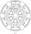
- SD-1 is the permanent magnet sub-domain
- SD-2 is the air gap sub-domain
- SD-3 is the slot sub-domain
- SD-4 is the slot opening sub-domain.
- a method for evaluating electromagnetic performance of a PM machine establishing an electromagnetic analytical model of the machine, the solution domain of the analytical model being at least divided into a permanent magnet sub-domain, an air gap sub-domain, and a stator slot sub-domain, and calculating the current magnetic field distributions of the air gap sub-domain, stator slot sub-domain and /or permanent magnet sub-domain based on a sub-domain method by the analytical model through a Poisson equation or a Laplace equation; adding an equivalent current sheet to the boundary of the target sub-domain and interface between the target sub-domain and a adjacent sub-domain respectively, representing the boundary condition and interface condition by the current density of the equivalent current sheet, and solving the magnetic field distribution by a sub-domain method; solving the magnetic potential difference of each part of the core by a magnetic circuit method according to the current magnetic field distribution, and converting the magnetic potential difference to a current density of the equivalent current sheet; iterating the magnetic field distribution obtained by the sub-domain method and the current density obtained by the magnetic circuit method until a convergent current
- the two-dimensional magnetic circuit is used as the target magnetic field of the analytical model, and the solution domain is divided on a 2D plane of the analytical model.
- the undetermined coefficients in each sub-domain expression are solved by simultaneous equations, and the equation set is written as a matrix form.
- the silicon steel of stator core tooth portion and yoke portion is equivalent to different magnetic reluctance to construct a magnetic network, and the obtained current magnetic field distribution is converted into the magnetic flux into the stator as a magnetic flux source in the magnetic circuit method, to obtain the magnetic potential difference of each stator tooth and stator yoke by solving, the magnetic potential difference of the stator tooth and stator yoke is equivalent to the current density of equivalent current sheets on the slot side and slot bottom.
- a node magnetic potential difference matrix equation is constructed according to kirchhoffs law, and then a convergent solution of the node magnetic potential difference matrix is obtained using Newton-Raphson's law.
- the current density of the equivalent current sheet is preset to 0, and the sub-domain method is used to solve the magnetic field distribution for the first time, to obtain the magnetic flux into the stator; then the magnetic potential difference of each tooth portion and yoke portion of the stator is solved by the magnetic circuit method, and the current density value of corresponding equivalent current sheet is obtained by the magnetic potential difference; then current density value is used as a boundary condition of the sub-domain method to resolve; the above iterative process is repeated until the difference between the current density obtained in the previous iteration and the current density obtained in this iteration is within the preset threshold range.
- a magnetic network is established at the rotor yoke to calculate the current density of the equivalent current sheet between the rotor yoke and the rotor permanent magnet, and the current density is taken as the boundary condition at the interface between the rotor yoke and the rotor permanent magnet.
- the stator slot sub-domain includes a boundary condition of two slot sides and a boundary condition of the slot bottom, and the boundary condition is expressed as: H 3 ri
- J i 1 is the current density of the equivalent current sheet on the first slot side of the stator slot
- J i 2 is the current density of the equivalent current sheet on the second slot side of the stator slot
- J i 3 is the current density of the equivalent current sheet at the slot bottom of the stator slot.
- the stator slot is a semi-closed slot
- the stator slot sub-domain includes boundary conditions of two slot sides and the boundary condition of both sides of the slot opening.
- the boundary condition is expressed as: H 3 ri
- b oa is the width of slot opening
- J i 1 is the current density of the equivalent current sheet on the first slot side of the stator slot
- J i 2 is the current density of the equivalent current sheet on the second slot side of the stator slot
- the permanent magnet pole of the rotor is a consequent-pole, and a soft magnetic material is added between two adjacent permanent magnets.
- the non-consequent-pole has a permanent magnet sub-domain range of 0-2 ⁇ , and the range of the consequent-pole machine permanent magnet sub-domain is: ⁇ im ⁇ ⁇ mag / 2 ⁇ ⁇ ⁇ ⁇ im + ⁇ mag / 2
- ⁇ mag is the width angle of the permanent magnet
- ⁇ im is the center line of the i-th permanent magnet.
- the consequent-pole rotor permanent magnet sub-domain is added with the boundary condition on the interface with the adjacent soft magnetic material, and the boundary condition is represented by the magnetic flux density: B rmi
- Example 1 Electromagnetic analytical model of a surface-mounted permanent magnet machine
- the present invention is applied to a surface-mounted permanent magnet machine electromagnetic design, and a 4-pole 6-slot surface-mounted permanent magnet machine is taken as an example, but the number of pole slots of the machine is not limited to the examples of this embodiment.
- the stator of the surface-mounted permanent magnet machine herein is a nonlinear silicon steel
- SD-1, SD-2 and SD-3 are sub-domains of permanent magnets, air gap and stator slot
- ⁇ r is the rotor rotational angular velocity
- ⁇ i is the angle of the centerline of the i-th slot
- r and a are the radial and tangential positions in the polar coordinate system
- b sa is the width of slot opening
- R r , R m , R s and R sb are the radius of rotor yoke
- ⁇ 0 is the initial angle of the rotor
- k and n are the number of harmonics on the circumference and the slot opening, respectively
- p is the number of poles of the permanent magnet.
- the magnetic circuit method is used to solve the magnetic potential difference of each part of the stator, and is converted into the current density of the equivalent current sheet in the slot. Then iteration is performed by the sub-domain method and magnetic circuit method, to calculate the convergent solution of the magnetic field distribution of each sub-domain. Based on the convergence result, electromagnetic performance such as permanent magnet machine flux linkage, counter electromotive force, cogging torque, terminal voltage, electromagnetic torque, and unbalance force are calculated.
- a z 1 ⁇ k C 1 k A 1 + C 2 k M ⁇ ck ⁇ C 3 k M rsk cos k ⁇ + ⁇ k C 1 k C 1 + C 2 k M ⁇ sk + C 3 k M rck sin k ⁇
- a z 2 ⁇ k A 2 r / R s k + B 2 r / R m ⁇ k cos k ⁇ + ⁇ k C 2 r / R s k + D 2 r / R m ⁇ k sin k ⁇
- B 1 r ⁇ ⁇ k k / r ⁇ C 1 k A 1 + C 2 k M ⁇ ck ⁇ C 3 k M rsk sin k ⁇ + ⁇ k k / r ⁇ C 1 k C 1 + C 2 k M ⁇ sk + C 3 k M rck cos k ⁇
- B 1 ⁇ ⁇ ⁇ k 1 / r ⁇ C 4 k A 1 + C 5 k M ⁇ ck ⁇ C 6 k M rsk cos k ⁇ ⁇ ⁇ k 1 / r ⁇ C 4 k C 1 + C 5 k M ⁇ sk + C 6 k M rck sin k ⁇
- B 2 r ⁇ ⁇ k k / r ⁇ A 2 r / R s k + B 2 r / R m ⁇ k sin k ⁇ + ⁇ k k / r ⁇ C 2 r / R s k + D 2 r / R m ⁇ k cos k ⁇
- B 2 ⁇ ⁇ ⁇ k k / r ⁇ A 2 r / R s k ⁇ B 2 r / R m k cos k ⁇ ⁇ ⁇ k k / r ⁇ C 2 r / R s k ⁇ D 2 r / R m ⁇ k sin k ⁇
- a 1 , B 1 , A 2 , B 2 , C 2 and D 2 are undetermined coefficients
- M rsk , M rck , M ⁇ sk , and M ⁇ ck are magnetization components of the permanent magnet:
- M rck M rk cos k ⁇ r t + k ⁇ 0
- M rsk M rk sin k ⁇ r t + k ⁇ 0
- M ⁇ ck ⁇ M ⁇ k sin k ⁇ r t + k ⁇ 0
- M ⁇ sk M ⁇ k cos k ⁇ r t + k ⁇ 0
- the vector magnetic potential A z 3 in the slot satisfies the Poisson equation. If it is no-load, the current density of the armature in the equation is set to 0, and its boundary condition can be expressed as: H 3 ri
- J i 1 , J i 2 and J i 3 are the current density of equivalent current sheets on three sides of the slot, the value of which is determined by the magnetic circuit method.
- a z 3 i r ⁇ ⁇ n A z 3 in cos E n ⁇ + b sa / 2 ⁇ ⁇ i + A z 3 i 0
- a z 3 in B 3 n G 3 ⁇ E n W n R sb 1 ⁇ E n 2 ⁇ 2 ⁇ 0 J amn R sb 2 E n E n 2 ⁇ 4 r R sb E n + B 3 n r R s ⁇ E n + rE n 2 W n 1 ⁇ E n 2 + ⁇ 0 J amn r 2 E n 2 ⁇ 4
- a z 3 i 0 ⁇ 0 J am 0 2 R sb 2 ln r ⁇ r 2 / 4 + C i ln r ⁇ ⁇ 0 J i 1 + J i 2 r / b
- ⁇ i is the angle of the centerline of the i-th groove
- r and a are the radial and tangential positions in the polar coordinate system
- b sa is the width of slot opening
- R s and R sb are the radius of the slot top and the slot bottom to the center of the circle, respectively.
- J ami 1 and J ami 2 are the current density of the two coil sides in the i-th slot. If it is no-load, the current density of the coil is 0, and B 3 in and Q 3 i are undetermined coefficients.
- a zb 3 i r ⁇ ⁇ n A zb 3 in cos E n + ⁇ + b sa / 2 ⁇ ⁇ i + A zb 3 i 0
- a zb 3 i 0 ⁇ ⁇ 0 J i 1 + J i 2 r / b sa + C i ln r + ⁇ 0 J ian 2 2 R sb 2 ln r ⁇ r 2 / 4 + Q 3 bi
- a zb 3 in B 3 n G 3 ⁇ E n W n R sb / 1 ⁇ E n 2 r / R sb E n + B 3 n r / R s ⁇ E n + rE n 2 W n / 1 ⁇ E n 2 slot bottom radial magnetic flux density magnetic flux density :
- B b 3 ir ⁇
- a zt 3 i r ⁇ ⁇ n A zt 3 in cos E n ⁇ + b sa / 2 ⁇ ⁇ i + A zt 3 i 0
- a zt 3 i 0 ⁇ ⁇ 0 r J i 1 + J i 2 / b sa + C i ln r + C ti ln r ⁇ ⁇ 0 J iam 1 r 2 / 4 + Q 3 ti
- a zt 3 in B 3 tn G 3 ⁇ E n W n R sb / 1 ⁇ E n 2 r / R sb E n + B 3 tn r / R s ⁇ E n + rE n 2 W n / 1 ⁇ E n 2
- step 2) the silicon steel of stator core tooth portion and yoke portion is equivalent to different magnetic reluctance to construct a magnetic network, and the obtained current magnetic field distribution is converted into the magnetic flux into the stator as a magnetic flux source in the magnetic circuit method, to obtain the magnetic potential difference of each stator tooth and stator yoke by solving, the magnetic potential difference of the stator tooth and stator yoke is equivalent to the current density of equivalent current sheets on the slot side and slot bottom.
- a node magnetic potential difference matrix equation is constructed according to kirchhoffs law, and then a convergent solution of the node magnetic potential difference matrix is obtained using Newton-Raphson's law.
- the current density of the equivalent current sheet is preset to 0, and the sub-domain method is used to solve the magnetic field distribution for the first time, to obtain the magnetic flux into the stator; then the magnetic potential difference of each tooth portion and yoke portion of the stator is solved by the magnetic circuit method, and the current density value of corresponding equivalent current sheet is obtained by the magnetic potential difference; then current density value is used as a boundary condition of the sub-domain method to resolve; the above iterative process is repeated until a stable current density of the equivalent current sheet is obtained.
- the flux linkage, counter electromotive force, the cogging torque of the permanent magnet machine can be calculated under no-load condition; and under load conditions, the terminal voltage, total torque and other electromagnetic performance of the permanent magnet machine can be calculated.
- the main process is as follows: The calculation of the machine flux linkage is divided into two cases: non-overlapping winding and overlapping winding.
- Z 0 R sb 2 ⁇ R s 2 g Q 3 i / 2 ⁇ ⁇ 0 J i 1 + J i 2 R sb 3 ⁇ R s 3 / 3 b sa + C i 2 R sb 2 ln R sb ⁇ 2 R s 2 ln R s + R s 2 ⁇ R sb 2 / 4
- Z n B 3 in G 3 ⁇ E n W in R sb / 1 ⁇ E n 2 g R sb
- Z b 0 ⁇ ⁇ 0 J i 1 + J i 2 R sb 3 ⁇ R sm 3 / 3 b sa + R sb 2 ⁇ R sm 2 Q 3 i / 2 + C i 2 R sb 2 ln R sb ⁇ 2 R sm 2 ln R m + R sm 2 ⁇ R sb 2 / 4
- Z t 0 ⁇ ⁇ 0 J i 1 + J i 2 R sm 3 ⁇ R s 3 / 3 b sa + R sm 2 ⁇ R s 2 Q 3 i / 2 + C i 2
- ⁇ ph is the total flux linkage of a phase, which is obtained by superimposing the flux linkages of all relevant coil sides.
- the rotor yoke is regarded as infinite permeability to simplify the model and speed up the solving; for some unconventional permanent magnet machines that need to consider the rotator saturation, similar to the stator, an equivalent current sheet is added between the permanent magnet and the rotor yoke to replace the magnetic potential difference of the rotor yoke.
- the no-load and load conditions of one set of 8-pole 24-slot surface-mounted permanent magnet machine are calculated respectively, and its main parameters are shown in Table 1.
- the calculation results are compared with the results obtained by the two-dimensional finite element calculation program.
- the present invention Four methods are used for electromagnetic analysis and solution of the machine, respectively the present invention, the finite element nonlinear algorithm, the sub-domain method, and the finite element linear algorithm.
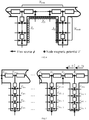
- the magnetic circuit model of the variable magnetic reluctance number used in the present invention refer to FIG.4 .
- the stator silicon steel is divided into a tooth portion and a yoke portion, which are all equivalent to equivalent resistance.
- the number of equivalent magnetic reluctances can be determined by the saturation of the stator, and the magnetic flux ⁇ entering from the air gap and slot is determined by the sub-domain, and the convergence result is obtained by the Kirchhoffs law and Newton-Raphson method, to obtain the node voltage of each node.
- FIG.5 shows the correspondence relationship between the equivalent current sheet current density and the magnetic potential difference.
- the present invention improves the traditional sub-domain method and combines it with the magnetic circuit method.
- the improved sub-domain method is used to accurately calculate the magnetic field distribution in permanent magnets, air gaps and slots, and then integration of the magnetic flux density and its area entering the stator is performed, converted to magnetic flux.
- the magnetic flux is used as the input of the magnetic circuit, to analyze the saturation of the stator. According to different saturation situations, that is, the different magnetic potential difference of the tooth portion and the yoke portion, the current density of the equivalent current sheet is solved, and the current density is used as the input of the improved magnetic circuit method to solve the magnetic field distribution. Therefore, the algorithm proposed in this patent has an iterative process, and the convergent solution is a magnetic field distribution in consideration of the nonlinearity of the stator silicon steel sheet.
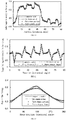
- FIG.6 to IG.10 show the no-load magnetic field analysis results obtained by the four methods.
- FIG.6 and FIG.7 show the radial magnetic flux density and tangential magnetic flux density in the air gap predicted by the four methods.
- FIG. 8, FIG. 9 and FIG. 10 are A-phase flux linkage, A-phase counter electromotive force, and cogging torque predicted by four methods.
- FIG.11-FIG.15 The analysis results of the load magnetic field obtained by four methods are shown in FIG.11-FIG.15 .
- FIG.11 and FIG.12 are the radial magnetic flux density and tangential magnetic flux density in the air gap predicted by the four methods.
- FIG. 13 , FIG. 14 and FIG. 15 are phase A flux linkages, phase A induced electromotive force and total torque predicted by four methods.
- the prediction results of the present invention are highly consistent with the finite element nonlinear algorithm, and the sub-domain method is highly consistent with the finite element linear algorithm.
- the nonlinearity of the prototype is a characteristic that must be considered. Therefore, the non-linear algorithm proposed by the present invention has higher calculation accuracy than that of the sub-domain method and the finite element linear algorithm.
- the non-linear algorithm proposed by the present invention can provide suggestions for optimization because the machine performance corresponds to the size of the machine.
- the above process includes 61 field calculation points in one electrical cycle.
- the four methods use the same computer, with CPU of i7-7700.
- the finite element method is based on the Ansys Maxwell platform, and the present invention and the sub-domain method are based on MATLAB.
- the number of meshes in the finite element model is 23,750.
- Table 2 shows the calculation time of the four methods for the machine under no-load and load conditions. It can be observed from the table, the model proposed by the present invention can greatly save the solving time compared to the conventional finite element model.
- Table 2 Calculation time(s)
- the invention Finite element nonlinear algorithm Conventional sub-domain method Finite element linear algorithm No-load 13 230 0.64 197 Load 16.92 287 0.78 216
- an analytical model of two-dimensional magnetic circuit is used; when the object of this embodiment is a three-dimensional magnetic circuit, an analytical model of three-dimensional magnetic circuit can be used, as long as the boundary condition of the corresponding analytical model are set to the boundary condition of this embodiment.
- Example 2 analytical model of surface-mounted permanent magnet machine with tooth tips
- FIG. 17 shows an applicable non-linear composite model when the surface-mounted permanent magnet machine has tooth tips.
- SD-1 is a permanent magnet sub-domain
- SD-2 is an air gap sub-domain
- SD-3 is a slot sub-domain
- SD-4 is a slot opening sub-domain.
- an equivalent current sheet is added to the slot opening part to simulate the non-linear effect of the tooth tip part.
- two slot sides of the slot opening sub-domain SD-4 add the current density of the equivalent current sheet as a boundary condition of slot opening sub-domain SD -4 when boundary conditions are set for the sub-domain method.
- Other calculation processes for example, the iteration way of the magnetic circuit method, the sub-domain method and the magnetic circuit method is the same as that of Example 1, and is not described again.
- an analytical model of two-dimensional magnetic circuit is used; when the object of this embodiment is a three-dimensional magnetic circuit, an analytical model of three-dimensional magnetic circuit can be used, as long as the boundary condition of the corresponding analytical model are set to the boundary condition of this embodiment.
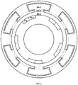
- FIG.18 shows an applicable composite model of an external rotor surface-mounted permanent magnet machine considering the nonlinear effects of the rotor.
- an equivalent current sheet is added between the permanent magnet and the rotor yoke to simulate the nonlinear effect of the rotor yoke.
- the boundary conditions of sub-domain method comprise a current density of equivalent current sheets at the interface between the rotor permanent magnet SD-1 and the rotor yoke as a boundary condition, the boundary condition of stator slot sub-domain SD-3 and the boundary condition of slot opening sub-domain SD-2.
- Other calculation processes, for example, the iteration way of the magnetic circuit method, the sub-domain method and the magnetic circuit method is the same as that of Examples 1 and 2, and is not described again.
- an analytical model of two-dimensional magnetic circuit is used; when the object of this embodiment is a three-dimensional magnetic circuit, an analytical model of three-dimensional magnetic circuit can be used, as long as the boundary condition of the corresponding analytical model are set to the boundary condition of this embodiment.
- stator slot of this permanent magnet machine is an open slot (i.e., without slot opening SD-2)
- an equivalent current sheet is added between the permanent magnet and the rotor yoke to simulate the nonlinear effect of the rotor yoke.
- the boundary conditions of sub-domain method comprise a current density of equivalent current sheets at the interface between the rotor permanent magnet SD-1 and the rotor yoke, the equivalent current density of two slot sides of stator slot sub-domain SD-3 and the equivalent current density of slot bottom.
- Other calculation processes, for example, the iteration way of the magnetic circuit method, the sub-domain method and the magnetic circuit method is the same as that of Example 1 and is not described again.
- Example 4 Electromagnetic analytical model of a dual-stator surface-mounted permanent magnet machine
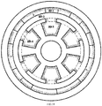
- FIG. 19 shows an applicable nonlinear composite model of a dual-stator surface-mounted permanent magnet machine.
- the difference between this embodiment and Example 1 is that: SD-7 in internal stator slot, SD-5 in internal stator slot opening, SD-6 in external stator slot and SD-4 in external stator slot opening have been added with equivalent current sheet to simulate non-linear effects inside and outside the status core. That is, the boundary conditions of sub-domain method comprise equivalent current density of two slot sides and one slot bottom of the internal stator slot SD-7, equivalent current density of two slot sides of the internal stator slot opening SD-5, the equivalent current density of two slot sides and one slot bottom of external stator slot SD-6, and the equivalent current density of two slot sides of the external stator slot opening SD-4.
- Other calculation processes, for example, the iteration way of the magnetic circuit method, the sub-domain method and the magnetic circuit method is the same as that of Example 1 and is not described again.
- an analytical model of two-dimensional magnetic circuit is used; when the object of this embodiment is a three-dimensional magnetic circuit, an analytical model of three-dimensional magnetic circuit can be used, as long as the boundary condition of the corresponding analytical model are set to the boundary condition of this embodiment.
- Example 5 electromagnetic analytical model of a dual-stator consequent-pole permanent magnet machine
- FIG.20 shows an applicable nonlinear composite model of a dual-stator consequent-pole permanent magnet machine.
- the range of consequent-pole machine permanent magnet sub-domain is ⁇ im - ⁇ mag / 2 ⁇ ⁇ ⁇ ⁇ im + ⁇ mag / 2; where amag is the width angle of the permanent magnet, ⁇ im is the center line of the i-th permanent magnet, the consequent-pole rotor permanent magnet sub-domain adds the boundary condition on the interface with the adjacent soft magnetic material, and the boundary condition is represented by the magnetic flux density: B rmi
- the boundary conditions of sub-domain method comprise the equivalent current density of two slot sides and one slot bottom of the internal stator slot SD-7, the equivalent current density of two slot sides of the internal stator slot opening SD-5, equivalent current density of two slot sides and one slot bottom of the external stator slot SD-6, and the equivalent current density of two slot sides of the external stator slot opening SD-4, and the consequent-pole rotorpermanent magnet sub-domain is added with the boundary condition on the interface with the adjacent soft magnetic material, and the boundary condition is represented by the magnetic flux density: B rmi
- B rmi represents the radial magnetic flux density in the permanent magnet.
- an analytical model of two-dimensional magnetic circuit is used; when the object of this embodiment is a three-dimensional magnetic circuit, an analytical model of three-dimensional magnetic circuit can be used, as long as the boundary condition of the corresponding analytical model are set to the boundary condition of this embodiment.
- Example 6 analytical model of a surface plug-in consequent-pole permanent magnet machine
- FIG.21 shows an applicable nonlinear composite model of a surface plug-in consequent-pole permanent magnet machine.
- This embodiment is an internal rotor electron and has only one stator.
- the boundary conditions of the sub-domain method of this embodiment comprise the equivalent current density of two slot sides and one slot bottom of the internal stator slot SD-3, the equivalent current density of two slot sides of the stator slot opening SD-4, and the consequent-pole rotor permanent magnet sub-domain is added with a boundary condition on the interface with the adjacent soft magnetic material, and the boundary condition is represented by the magnetic flux density: B rmi
- B rmi represents the radial magnetic flux density in the permanent magnet.
- Other calculation processes, for example, the iteration way of the magnetic circuit method, the sub-domain method and the magnetic circuit method is the same as that of Examples 1 and 5 and is not described again.
- an analytical model of two-dimensional magnetic circuit is used; when the object of this embodiment is a three-dimensional magnetic circuit, an analytical model of three-dimensional magnetic circuit can be used, as long as the boundary condition of the corresponding analytical model are set to the boundary condition of this embodiment.
- Example 7 analytical model of a V-shaped built-in internal rotorpermanent magnet machine
- FIG.22 shows an applicable nonlinear composite model of aV-shaped built-in internal rotor permanent magnet machine.
- the permanent magnets of the rotor portion are arranged in a V-shape, and are provided with a magnetically isolated magnetic bridge.
- Permanent magnet and rotor yoke are solved by magnetic circuit method, while air gap and slot are solved by sub-domain method considering current density. Equivalent current sheet is added in stator slot and slot opening to simulate nonlinear effects in core .
- boundary conditions of sub-domain method comprise: the equivalent current density of two slot sides and one slot bottom of the stator slot sub-domain SD-2, the equivalent current density of two slot sides of the slot opening sub-domain SD-3, and the equivalent current density on the interface between the rotor and the air gap sub-domain SD-1.
- boundary conditions of sub-domain method comprise: the equivalent current density of two slot sides and one slot bottom of the stator slot sub-domain SD-2, the equivalent current density of two slot sides of the slot opening sub-domain SD-3, and the equivalent current density on the interface between the rotor and the air gap sub-domain SD-1.
- an analytical model of two-dimensional magnetic circuit is used; when the object of this embodiment is a three-dimensional magnetic circuit, an analytical model of three-dimensional magnetic circuit can be used, as long as the boundary condition of the corresponding analytical model are set to the boundary condition of this embodiment.
- Example 8 electromagnetic analytical model of I-type built-in internal rotorpermanent magnet machine
- FIG.23 shows an applicable nonlinear composite model of an I-shaped built-in internal rotor permanent magnet machine.
- the permanent magnets of the rotor portion are arranged in a I-shape, and are provided with a magnetically isolated magnetic bridge.
- Permanent magnet and rotor yoke are solved by magnetic circuit method, while air gap and slot are solved by sub-domain method considering current density. Equivalent current sheet is added in stator slot and slot opening to simulate nonlinear effects in core.
- boundary conditions of sub-domain method comprise: the equivalent current density of two slot sides and one slot bottom of the stator slot sub-domain SD-2, the equivalent current density of two slot sides of the slot opening sub-domain SD-3, and the equivalent current density on the interface between the rotor and the air gap sub-domain SD-1.
- boundary conditions of sub-domain method comprise: the equivalent current density of two slot sides and one slot bottom of the stator slot sub-domain SD-2, the equivalent current density of two slot sides of the slot opening sub-domain SD-3, and the equivalent current density on the interface between the rotor and the air gap sub-domain SD-1.
- an analytical model of two-dimensional magnetic circuit is used; when the object of this embodiment is a three-dimensional magnetic circuit, an analytical model of three-dimensional magnetic circuit can be used, as long as the boundary condition of the corresponding analytical model are set to the boundary condition of this embodiment.
- FIG.24 is one of the magnetic circuit models used in FIG.22 and FIG.23 .
- the idea of solving the nonlinear composite model of the built-in permanent magnet machine is described as follows: 1. Establish the entire machine magnetic network model and use the magnetic circuit method to solve the node magnetic pressure matrix. 2. According to the node magnetic pressure matrix, the magnetic potential difference between the nodes on the circumferential surface of the rotor can be calculated. Furthermore, the current density of the equivalent current sheet between each node on the circumferential surface can be obtained as the boundary condition of air gap sub-domain. At the same time, the current density of the equivalent current sheet at the edge of the stator core is calculated. The calculation method of the current density is the same as the foregoing method of the present invention, and the current density is used as the boundary condition.
- the sub-domain method is used to solve the magnetic field distribution of air gaps, slots, and slot openings (excluding permanent magnets). 4. The iterative process is performed.
- the magnetic flux entering the rotor surface calculated by the sub-domain method is used as the magnetic flux source of the rotor magnetic circuit to calculate the rotor magnetic circuit, to obtain a new equivalent current density of the rotor circumferential surface.
- the magnetic flux entering the stator calculated by the sub-domain method is used as the magnetic flux source of the stator magnetic circuit, to solve the stator magnetic circuit and obtain a new equivalent current density on the stator surface.
- the equivalent current density on the rotor and stator is used as the boundary condition for the new round of sub-domain method calculations, until the current density error before and after the two iterations does not exceed the threshold, it is determined to be convergent, which is the final magnetic field distribution.
- Example 9 electromagnetic analytical model of a split-tooth permanent magnet vernier machine
- FIG.25 shows an applicable nonlinear composite model of a split-tooth permanent magnet vernier machine. Among them, an equivalent current sheet is added to the stator slot and the split tooth to be equivalent to the nonlinear effect in the stator core.
- boundary conditions of sub-domain method comprise: the equivalent current density of two slot sides and one slot bottom of the stator slot sub-domain SD-3, and the equivalent current density of two slot sides of the slot opening; and the equivalent current density of all slot sides and slot bottoms in the split tooth SD-4.
- boundary conditions of sub-domain method comprise: the equivalent current density of two slot sides and one slot bottom of the stator slot sub-domain SD-3, and the equivalent current density of two slot sides of the slot opening; and the equivalent current density of all slot sides and slot bottoms in the split tooth SD-4.
- an analytical model of two-dimensional magnetic circuit is used; when the object of this embodiment is a three-dimensional magnetic circuit, an analytical model of three-dimensional magnetic circuit can be used, as long as the boundary condition of the corresponding analytical model are set to the boundary condition of this embodiment.
- Example 10 A method for evaluating electromagnetic performance of a machine based on three-dimensional magnetic circuit
- a method for evaluating electromagnetic performance of a PM machine based on three-dimensional magnetic circuit comprising: establishing an analytical model by a three-dimensional magnetic circuit, the three-dimensional magnetic circuit including a plurality of sub-sheets divided by the non-ferromagnetic material in the axial direction, as shown in FIG.
- the solution domain of each sub-sheet being at least divided into a permanent magnet sub-domain, an air gap sub-domain, and a stator slot sub-domain, and calculating the current magnetic field distributions of the air gap sub-domain, stator slot sub-domain and /or permanent magnet sub-domain based on a sub-domain method by the analytical model through a Poisson equation or a Laplace equation; adding an equivalent current sheet to the boundary of the target sub-domain and interface between the target sub-domain and a adjacent sub-domain respectively, representing the boundary condition and interface condition by the current density of the equivalent current sheet, and solving the magnetic field distribution by a sub-domain method; the magnetic field node of all the sub-sheet being arranged in the same position, the magnetic field node at the same position of the adjacent sub-sheet being connected, the magnetic path connecting direction of the adjacent sub-sheets being axially connected, the magnetic reluctance distribution of all the sub-sheets and the connecting magnetic reluctance between adjacent sub-sheets forming a three-dimensional magnetic circuit
- the solving of the sub-domain method is the same as the above two-dimensional magnetic field analytical model.
- a three-dimensional magnetic field is constructed by the magnetic circuit method.
- the solving of three-dimensional magnetic field includes the magnetic reluctance in each sub-sheet and the connected magnetic reluctance between adjacent sub-sheets, and the other solving is the same as that of the two-dimensional magnetic field analytical model. Because of different temperature distribution at the axial direction, the degree of nonlinearity is different, and the magnetic field distribution of each sub-sheet is different; therefore, the uneven distribution of the magnetic field in the axial direction can be calculated by the sub-sheets elaborately, and for complex and diverse machine structures, the oblique pole and stator core discontinuity can be calculated.
- the axial sub-sheet methods of three-dimensional magnetic circuit are mainly divided into two types:
- the first type the nonlinear state of the stator core is different caused by the difference in temperature in the axial direction, that is, the BH curve of the stator core is different, so the part with similar nonlinearity (that is, the part that the same BH curve can be used) is used as a sub-sheet.
- the second type because of axially different structures, such as rotor block, oblique pole, stator slot discontinuity, etc., the part with the same axial section is used as a sub-sheet.
- each sub-sheet uses the respective BH curve to solve the magnetic reluctance of the current sheet; in the three-dimensional magnetic circuit, the stator core of each sub-sheet is equivalent to a two-dimensional magnetic circuit.
- the BH curve of the current sub-sheet is used to solve the magnetic reluctance in the sub-sheet.
- the same node position of the adjacent sub-sheets is connected by the connected magnetic reluctance, and the connected magnetic reluctance meter and the magnetic flux.
- the solution parameters of the entire three-dimensional magnetic circuit include the magnetic potential difference between the nodes in each sub-sheet and the magnetic potential difference between the same node positions of two adjacent sub-sheets.
- the solving by the magnetic circuit method can obtain the magnetic potential difference convergent solution of the three-dimensional magnetic circuit.
- the solving way of magnetic circuit method is the same as that of the two-dimensional magnetic circuit method, but the parameters of three-dimensional magnetic circuit include the magnetic reluctance of all sub-sheets and the connected magnetic reluctance between adjacent sub-sheets.
- each sub-sheet has its own BH curve because of the different temperatures.
- the magnetic circuit in each sub-sheet needs to be iterated according to their respective BH curve in the internal iterative process of the magnetic circuit, but the whole three-dimensional magnetic circuit (including the magnetic reluctance of the above meter and axial magnetic flux) is solved when solving.
- the two-dimensional magnetic circuit structure of each sub-sheet may be different, but even if the magnetic circuit structure is different, the arrangement of the magnetic field node is the same, and the three-dimensional magnetic circuit is connected by the magnetic field node at the same position; this sub-sheet mode is also a solution to the entire three-dimensional magnetic circuit.
- the detailed description of the iterative process of the three-dimensional magnetic circuit method is as follows:
- the external magnetic flux source injected into the magnetic circuit is fixed.
- the magnetic flux source (or magnetic field distribution) is obtained by the sub-domain method.
- B and H of each sub-sheet are determined according to the BH curve. Different abscissas H will correspond to different permeability.
- each magnetic reluctance is given an initial permeability, and the initial permeability is a random value.
- H corresponds to permeability ⁇ , and it is required to judge if the difference between the permeability ⁇ and the permeability ⁇ (or initial permeability ⁇ ) of the previous iteration is within the allowable error range. If it is, the permeability is determined to be converged; if not, the permeability is used as the current permeability to repeat the iterative calculation until the permeability converges.
- the convergent node magnetic potential difference is obtained from permeability, and the node magnetic potential difference is converted into equivalent current density.
- the equivalent current density is entered in the sub-domain method as the boundary condition to obtain the current magnetic field distribution; the current magnetic field distribution is entered into the magnetic circuit method to continue iteration to obtain a new converging magnetic potential difference; repeat this process until a convergent current density is obtained.
- FIG. 26 is a three-dimensional rotor model of permanent magnet block and oblique pole. According to the axial length sub-sheet of the permanent magnet 1, each sub-sheet uses a sub-domain method to solve the magnetic field distribution, and the status core (not shown in the figure) is solved by the magnetic circuit method based on a three-dimensional magnetic circuit.
- FIG. 27 is a three-dimensional stator model including an axial ventilation slot 3. In the axial direction, there is a ventilation slot 3 between adjacent status cores 2.
- the stator core 2 and ventilation slot 3 are on different sub-sheets.
- the magnetic field distribution is solved by the sub-domain method for each sub-sheet, and the stator core is solved by the magnetic circuit method based on the three-dimensional magnetic circuit.
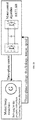
- FIG. 28 is a schematic diagram of co-simulation between the magnetic field distribution solved by the present invention and the control algorithm provided by MATLAB.
Landscapes
- Engineering & Computer Science (AREA)
- Physics & Mathematics (AREA)
- Power Engineering (AREA)
- General Physics & Mathematics (AREA)
- Geometry (AREA)
- Theoretical Computer Science (AREA)
- Manufacturing & Machinery (AREA)
- Evolutionary Computation (AREA)
- Computer Hardware Design (AREA)
- General Engineering & Computer Science (AREA)
- Electromagnetism (AREA)
- Computational Mathematics (AREA)
- Mathematical Analysis (AREA)
- Mathematical Optimization (AREA)
- Pure & Applied Mathematics (AREA)
- Iron Core Of Rotating Electric Machines (AREA)
Abstract
Description
- The present invention relates to the field of permanent magnet machine, and more particularly to methods for evaluating electromagnetic performance of electric machines in particular of permanent-magnet machine.
- Permanent magnet machines have received wide attention due to their high torque density, high power density and efficiency. In order to design permanent magnet machines that meet the use requirements and optimize them and shorten the design cycle, it is extremely important to select a suitable model for electromagnetic analysis at different machine design stages. For example, in the initial stage of machine design, designers often hope that the machine models can quickly solve problems and find the design direction; and in the later stage of machine design, designers hope that the machine models are as accurate as possible and close to the results of real object, to reduce errors.
- Existing models are divided into numerical models, analytical models, magnetic circuit models, and composite models. The numerical models can be used to solve the machine with complicated structure and accurately calculate the core saturation effect, but usually the solving time is too long, resulting in a long design cycle; moreover, the performance cannot directly correspond to the machine dimension parameters, therefore, it is difficult for performance optimization. The analytical method is fast for solving, and the machine performance is directly related to the dimension parameters, therefore, it can provide optimization. Usually the analytic method methods are divided into relative permeability method, complex permeability method, and sub-domain method. However, the analytical method can be used to solve the linear models only, that is, it is assumed that the machine stator and rotor yoke has infinite permeability, so the error will increase as the machine saturation increases. For magnetic circuit method, the nonlinearity of the core can be calculated by the Kirchoff's law and Newton-Raphson method; however, there are a large number of simplified processes in the magnetic circuit equivalent, which essentially discretizes a continuous field distribution, therefore, the magnetic field distribution cannot be accurately predicted.
- The present invention can accurately predict the tangential and radial magnetic field distribution in the permanent magnet body, the air gap and the stator slot by considering the nonlinearity of the machine core, and accurately calculate electromagnetic performance parameters such as the flux linkage of the machine, counter electromotive force, cogging torque, terminal voltage, total torque, imbalance force on the basis of the magnetic field distribution.
- A method for evaluating electromagnetic performance of a PM machine, comprising: establishing an electromagnetic analytical model of the machine, the solution domain of the analytical model being at least divided into a permanent magnet sub-domain, an air gap sub-domain, and a stator slot sub-domain, and calculating the current magnetic field distributions of the air gap sub-domain, stator slot sub-domain and/or permanent magnet sub-domain based on a sub-domain method by the analytical model through a Poisson equation or a Laplace equation; adding an equivalent current sheet to the boundary of the target sub-domain and interface between the target sub-domain and a adjacent sub-domain respectively, representing the boundary condition and interface condition by the current density of the equivalent current sheet, and solving the magnetic field distribution by a sub-domain method; solving the magnetic potential difference of each part of the core by a magnetic circuit method according to the current magnetic field distribution, and converting the magnetic potential difference to a current density of the equivalent current sheet ; iterating the magnetic field distribution obtained by the sub-domain method and the current density obtained by the magnetic circuit method until a convergent current density is obtained, solving the magnetic field distribution of the target sub-domain with the convergent current density; obtaining the electromagnetic performance evaluation results based on the electromagnetic performance parameter values obtained based on magnetic field distribution, the standard values of the electromagnetic performance parameters pre-stored in the processor or controller, and a comparison step of the calculated values and standard values of the electromagnetic performance parameters executed by the processor or controller..
- Each type of motor has its standard values of electromagnetic performance parameters. When the difference between the calculated value and the standard value of electromagnetic performance parameter is within the allowable error range, the electromagnetic performance of the motor is considered to meet the standard. If the difference exceeds the allowable error range, the electromagnetic performance of the motor is considered not to meet the standard. During the electromagnetic design phase of the motor, the method is executed on the computer processor. If the electromagnetic performance does not meet the standard, the design size of the motor needs to be modified until the electromagnetic performance of the motor meets the standard at the size. The method can be executed on a remote computer processor or a controller of the motor if the motor is in the running stage; and if the electromagnetic performance of the motor does not meet the standards, an early warning will be given.
- When it is required to calculate the magnetic field distribution of the status slot sub-domain, the stator slot sub-domain is the target sub-domain. After solving the magnetic field distribution of each sub-domain, electromagnetic performance parameters such as flux linkage, counter electromotive force, cogging torque, terminal voltage, load torque, unbalance force of the permanent magnet machine can be calculated according to the existing methods.
- The conventional sub-domain method assumes that both the stator and the rotor silicon steels have infinite permeability, so the saturation effect of the machine cannot be considered. In the present invention, considering that the saturation effect is essentially the existence of a magnetic potential difference in the stator, and by using Ampere's law, the magnetic potential difference can be equivalent to the current density of the equivalent current sheets on the slot side and slot bottom; and after equivalence, the stator silicon steel permeability can be reconsidered as infinity. This current value can be solved by the magnetic circuit method and as the boundary condition of the slot region in the sub-domain method. The magnetic flux into the stator is calculated by the sub-domain method, as a magnetic flux source in the magnetic circuit method. The magnetic circuit method provides a current density of equivalent current sheet for the sub-domain method, with iteration relationship between them, when the current density of the current sheet converges, it is considered as the final saturation, at this time, the result calculated by the sub-domain method is the magnetic field distribution of the permanent magnet machine in consideration of the saturation, and the electromagnetic performance of the machine can be obtained based on the magnetic field distribution.
- Preferably, when a vector magnetic potential expression of the stator slot sub-domain is established by the sub-domain method and the stator slot is an open slot, the boundary condition includes a boundary condition of the two slot sides and a boundary condition of the slot bottom, when calculating the vector magnetic potential expression of the permanent magnet sub-domain and the air gap sub-domain, the boundary condition is not changed; when the stator slot has a slot opening, the boundary condition includes the boundary condition of the two slot sides, the boundary condition of the slot bottom, and the boundary condition of the slot opening edge.
- According to the boundary condition and interface condition in each sub-domain, the undetermined coefficients in each sub-domain expression is solved by simultaneous equations, when compiling a program, the equations set is written as a matrix, and there is matrix inversion process when the undetermined coefficients are solving, and after the undetermined coefficients are solved, the magnetic field distribution in each sub-domain is obtained.
- For different stator slot types, the boundary conditions of stator slot sub-domains are different. The stator slots include open slots and semi-closed slots.
- For open slots, the stator slot sub-domain includes the boundary condition of slot side and the boundary condition of slot bottom, and the boundary condition is represented by: H 3ri | α = αi + bsa / 2 = J i1; H 3ri | α = αi -bsa / 2 = J i2; H 3αi | r = Rsb = - J i3; where, boa is the slot width, J i1, is the current density of the equivalent current sheet on the first slot side of the stator slot, J i2 is the current density of the equivalent current sheet on the second slot side of the stator slot, J i3 is the current density of the equivalent current sheet at the slot bottom of the stator slot.
- For semi-closed slots, the stator slot sub-domain includes the boundary condition of two slot sides and the boundary condition of the slot bottom, and the condition of two sides of the slot opening, and the boundary condition is represented by: H 3ri | α = αi + bsa / 2 = J i1; H 3ri | α = αi - bsa / 2 = -J i2; H 3αi | r = Rsb = -J i3; H 4ri | α = αi + boa / 2 = J i4; H 4ri | α = αi - boa / 2 = -J i5 ; where, boa is the width of slot opening, J i1 is the current density of the equivalent current sheet on the first slot side of the stator slot, J i2 is the current density of the equivalent current sheet on the second slot side of the stator slot, J i3 is the current density of the equivalent current sheet at the slot bottom of the stator slot; J i4 is the current density of the equivalent current sheet on the first slot side of the stator slot opening, J i5 is the current density of the equivalent current sheet on the second slot side of the stator slot opening.
- Considering the rotor saturation, in addition to the boundary condition of the stator slot sub-domain, the boundary condition at the interface between the rotor yoke and the permanent magnet should also be considered.
- When the rotor is a consequent-pole rotor, the range of the consequent-pole machine permanent magnet sub-domain is: αim - αmag / 2 ≤ α ≤ αim + αmag / 2; where, amag is the width angle of the permanent magnet, αim is the center line of the i-th permanent magnet, the consequent-pole rotor permanent magnet sub-domain is added with the boundary condition on the interface with the adjacent soft magnetic material, and the boundary condition is represented by the magnetic flux density: Brmi |α=αim ±αmag = 0, Brmi represents the radial magnetic flux density in the permanent magnet.
- The consequent-pole rotor means that the rotor comprises a permanent magnet and a soft magnetic material, and the permanent magnet and the soft magnetic material are spaced apart, that is, a soft magnetic material is added between two adjacent permanent magnets.
- When the rotor is a non-consequent-pole rotor, the permanent magnet sub-domain of the rotor is within the range of 0-2π, and the permanent magnet sub-domain of the rotor is added with a boundary condition at the interface between the permanent magnet and the rotor yoke, the boundary condition is represented by the current density of an equivalent current sheet.
- Preferably, the analytical model divides the solution domain on the 2D plane when the two-dimensional magnetic circuit is used as the target magnetic field of the analytical model.
- Preferably, when solving with the magnetic circuit method, the silicon steel of stator core tooth portion and yoke portion is equivalent to different magnetic reluctance to construct a magnetic network, and the obtained current magnetic field distribution is converted into the magnetic flux into the stator as a magnetic flux source in the magnetic circuit method, to obtain the magnetic potential difference of each stator tooth and stator yoke by solving, the magnetic potential difference of the stator tooth and stator yoke is equivalent to the current density of equivalent current sheets on the slot side and slot bottom. The current magnetic field distribution comprises the magnetic field distribution of the sub-domain with which all the stator cores are in direct contact, including the air gap sub-domain in addition to the stator slot sub-domain; that is, the magnetic field distribution in the air gap and slot obtained by the current sub-domain method is converted to a magnetic flux into the stator.
- When solving the magnetic potential difference of each stator tooth and stator yoke, a node magnetic potential difference matrix equation is constructed according to kirchhoff's law, and then a convergent solution of the node magnetic potential difference matrix is obtained using Newton-Raphson's law, where, the node magnetic potential difference matrix equation is: V = (AΛAT)-1Φ; where, A is the associated matrix, A is the branch magnetic reluctance matrix, V is the node magnetic potential difference matrix, Φ is the node magnetic flux matrix, and the magnetic flux into the stator is obtained by integrating the magnetic flux density and the area in the stator slot and the air gap.
- In the magnetic circuit method, there is a convergent solution for solving the node magnetic potential difference matrix by using the current magnetic field distribution cycle, indicating the magnetic field distribution of the stator core under the magnetic field distribution of the current sub-domain method and the convergent solution of the node magnetic potential difference matrix are equivalent to a current density.
- The convergence means that the difference of current density is less than an allowable error range.
- When considering the saturation of the rotor yoke, a magnetic network is established at the rotor yoke to calculate the current density of the equivalent current sheet between the rotor yoke and the rotor permanent magnet, and the current density is taken as the boundary condition at the interface between the rotor yoke and the rotor permanent magnet.
- Preferably, when iteration of the magnetic field distribution obtained by sub-domain method and the current density obtained by magnetic circuit method is performed, the current density of the equivalent current sheet is preset to 0, and the sub-domain method is used to solve the magnetic field distribution for the first time, to obtain the magnetic flux into the stator; then the magnetic potential difference of each tooth portion and yoke portion of the stator is solved by the magnetic circuit method, and the current density value of corresponding equivalent current sheet is obtained by the magnetic potential difference; then current density value is used as a boundary condition of the sub-domain method to resolve; the above iterative process is repeated until the difference between the current density obtained in the previous iteration and the current density obtained in this iteration is within the preset threshold range.
- The mutual iteration between the magnetic circuit method and the sub-domain method is: the current density obtained by the convergent solution of the node magnetic potential difference matrix is taken into the sub-domain method as a boundary condition and/or an interface condition, to obtain the current magnetic field distribution by the sub-domain method, then calculate the status core magnetic field distribution to judge if the current density of this time and the current density of the previous time are converged; and if not, the current magnetic field distribution is taken into the magnetic circuit method, to solve the convergent solution of the node magnetic potential difference matrix again, and repeat the iterations until the current density of this time and the current density of the previous time are converged.
A method for evaluating electromagnetic performance of a PM machine based on three-dimensional magnetic circuit, comprising:
establishing an analytical model by a three-dimensional magnetic circuit, wherein the three-dimensional magnetic circuit includes a plurality of sub-sheets divided by the non-ferromagnetic material in the axial direction, and the solution domain of each sub-sheet being at least divided into a permanent magnet sub-domain, an air gap sub-domain, and a stator slot sub-domain, and calculating the current magnetic field distributions of the air gap sub-domain, stator slot sub-domain and /or permanent magnet sub-domain based on a sub-domain method by the analytical model through a Poisson equation or a Laplace equation; adding an equivalent current sheet to the boundary of the target sub-domain and interface between the target sub-domain and a adjacent sub-domain respectively, representing the boundary condition and interface condition by the current density of the equivalent current sheet, and solving the magnetic field distribution by a sub-domain method; the magnetic field node of all the sub-sheet being arranged in the same position, the magnetic field node at the same position of the adjacent sub-sheet being connected, the magnetic path connecting direction of the adjacent sub-sheets being axially connected, the magnetic reluctance distribution of all the sub-sheets and the connecting magnetic reluctance between adjacent sub-sheets forming a three-dimensional magnetic circuit of the machine, and solving the magnetic potential difference convergent solution of the three-dimensional magnetic circuit method according to the magnetic circuit method, and converting magnetic potential difference convergent solution to a current density of the equivalent current sheet; iterating the magnetic field distribution obtained by the sub-domain method and the current density obtained by the magnetic circuit method until a convergent current density is obtained, solving the magnetic field distribution of the target sub-domain with the convergent current density; calculating the electromagnetic performance parameters based on the magnetic field distribution and evaluating the electromagnetic performance of the machine based on the electromagnetic performance parameters. - The solving of the sub-domain method is the same as the above two-dimensional magnetic field analytical model. A three-dimensional magnetic field is constructed by the magnetic circuit method. The solving of three-dimensional magnetic field includes the magnetic reluctance in each sub-sheet and the connected magnetic reluctance between adjacent sub-sheets, and the other solving is the same as that of the two-dimensional magnetic field analytical model. Because of different temperature distribution at the axial direction, the degree of nonlinearity is different, and the magnetic field distribution of each sub-sheet is different; therefore, the uneven distribution of the magnetic field in the axial direction can be calculated by the sub-sheets elaborately, and for complex and diverse machine structures, the oblique pole and stator core discontinuity can be calculated.
- The axial sub-sheets of the three-dimensional magnetic field are different in the nonlinear state of the stator core caused by the difference in temperature in the axial direction, that is, the BH curve of the stator core is different, so the part with similar nonlinearity (that is, the part that the same BH curve can be used) is used as a sub-sheet; or because of axially different structures, such as rotor block, oblique pole, stator slot discontinuity, etc., the part with the same axial section is used as a sub-sheet.
- Regardless of the sub-sheet method, the position of the magnetic field node in all sub-sheets is the same, each sub-sheet uses the respective BH curve to solve the magnetic reluctance of the current sheet; in the three-dimensional magnetic circuit, the stator core of each sub-sheet is equivalent to a two-dimensional magnetic circuit. The BH curve of the current sub-sheet is used to solve the magnetic reluctance in the sub-sheet. The same node position of the adjacent sub-sheets is connected by the connected magnetic reluctance, and the connected magnetic reluctance meter and the magnetic flux. The solution parameters of the entire three-dimensional magnetic circuit include the magnetic potential difference between the nodes in each sub-sheet and the magnetic potential difference between the same node positions of two adjacent sub-sheets. The solving by the magnetic circuit method can obtain the magnetic potential difference convergent solution of the three-dimensional magnetic circuit. The solving way of magnetic circuit method is the same as that of the two-dimensional magnetic circuit method, but the parameters of three-dimensional magnetic circuit include the magnetic reluctance of all sub-sheets and the connected magnetic reluctance between adjacent sub-sheets.
- For the first sub-sheet mode, each sub-sheet has its own BH curve because of the different temperatures. When solving the entire nonlinear three-dimensional magnetic circuit, the magnetic circuit in each sub-sheet needs to be iterated according to their respective BH curve in the internal iterative process of the magnetic circuit, but the whole three-dimensional magnetic circuit (including the magnetic reluctance of the above meter and axial magnetic flux) is solved when solving. For the second sub-sheet mode, because the magnetic reluctance structure of each sub-sheet is different, the two-dimensional magnetic circuit structure of each sub-sheet may be different, but even if the magnetic circuit structure is different, the arrangement of the magnetic field node is the same, and the three-dimensional magnetic circuit is connected by the magnetic field node at the same position; this sub-sheet mode is also a solution to the entire three-dimensional magnetic circuit.
- Regardless of a two-dimensional magnetic circuit or a three-dimensional magnetic circuit, the solving method of the magnetic circuit method is the same. In the two-dimensional magnetic circuit, the parameters solved by the magnetic circuit method are the magnetic reluctance in the two-dimensional magnetic circuit; in the three-dimensional magnetic circuit, the parameters solved by the magnetic circuit method include, in addition to the magnetic reluctance in each sub-sheet, the connected magnetic reluctance between adjacent sub-sheets, the magnetic reluctance and connected magnetic reluctance in the sub-sheet. These parameters are used as magnetic field distribution parameters of the three-dimensional magnetic circuit.
- The present invention has the following advantages. The non-linear machine core is equivalent to the complex of the linear stator and the equivalent current sheet, and the nonlinearity of the core is characterized by the equivalent current sheet. The sub-domain method is used to analyze and calculate the linear stator model and calculate the magnetic field distribution of the stator; the magnetic circuit method is used to calculate the nonlinearity of the core to obtain the current density of the equivalent current sheet. The magnetic field distribution obtained by the sub-domain method and the current density obtained by the magnetic circuit method are iterated to finally obtain a stable current density, and thus accurately calculate the magnetic field distribution and electromagnetic performance parameters. With the advantages of the sub-domain method and the magnetic circuit method, the present invention can accurately calculate the magnetic field distribution and electromagnetic performance of the permanent magnet machine in consideration of the saturation effect, with a fast calculation speed and high precision.
- In addition, the present invention can be extended to the solution of machine dynamic characteristics. For considering the machine control algorithm, the complex structure of the machine and the material nonlinearity, usually the finite element method and MATLAB SIMULINK are combined for simulation in the prior art, but the solving speed is too slow, usually it will take a few days to complete the simulation. If the present invention combines with MATLAB for simulation, the solving time will be greatly shortened. In addition, the present invention can also be implemented by MATLAB; therefore, it can be integrated into unified software to facilitate operation.
-
-
FIG. 1 is a schematic diagram of a model of a nonlinear surface-mounted permanent magnet machine of the present invention. -
FIG. 2 is a nonlinear composite model in which an equivalent current sheet is added as a boundary condition. -
FIG. 3 is a flow chart of a solving method of the present invention when used in electromagnetic design no-load condition of a surface-mounted permanent magnet machine. -
FIG. 4 shows a magnetic circuit of variable magnetic reluctance numbers used by the magnetic circuit method in the embodiment of the present invention. The more severity the saturation condition, the more magnetic reluctance numbers selected. -
FIG. 5 shows a correspondence relationship between the equivalent current sheet current density and the magnetic potential difference of the magnetic circuit used under load conditions according to the embodiment of the present invention. -
FIG. 6 is a schematic diagram for comparing the predicted radial magnetic flux density in the air gap under no-load conditions between the present invention and other three methods. -
FIG. 7 is a schematic diagram for comparing the predicted tangential magnetic flux density in the air gap under no-load conditions between the present invention and other three methods. -
FIG. 8 is a schematic diagram comparing the predicted A-phase flux linkage under no-load conditions between the present invention and other three methods. -
FIG. 9 is a schematic diagram for comparing the predicted A-phase counter electromotive force under no-load conditions between the present invention and other three methods. -
FIG. 10 is a schematic diagram for comparing the predicted cogging torque under no-load conditions between the present invention and other three methods. -
FIG. 11 is a schematic diagram for comparing the predicted radial magnetic flux density in the air gap under load conditions between the present invention and other three methods. -
FIG. 12 is a schematic diagram for comparing the predicted tangential magnetic flux density in the air gap under load conditions between the present invention and other three methods. -
FIG. 13 is a schematic diagram for comparing the predicted A-phase flux linkage under load conditions between the present invention and other three methods. -
FIG. 14 is a schematic diagram for comparing the predicted A-phase induced electromotive force under load conditions between the present invention and other three methods. -
FIG. 15 is a schematic diagram of the predicted total torque and the prototype experimental results under load conditions between the present invention and other three methods. -
FIG. 16 is a schematic diagram of a three-dimensional magnetic circuit in which sub-sheets are axially connected by taking two sub-sheets as an example. -
FIG. 17 is a nonlinear composite model suitable for use when a surface-mounted permanent magnet machine has tooth tips. -
FIG. 18 is a composite model of an outer rotor surface-mounted permanent magnet machine suitable for consideration of the rotor nonlinear effects. -
FIG. 19 is a nonlinear composite model suitable for a dual-stator surface-mounted permanent magnet machine. -
FIG. 20 is a nonlinear composite model suitable for a dual-stator consequent-pole permanent magnet machine. -
FIG. 21 is a nonlinear composite model suitable for a surface plug-in consequent-pole permanent magnet machine. -
FIG. 22 is a nonlinear composite model suitable for a V-shaped built-in internal rotor permanent magnet machine. -
FIG. 23 is a nonlinear composite model suitable for an I-shaped built-in internal rotor permanent magnet machine. -
FIG. 24 is a magnetic circuit model used inFIG. 22 andFIG. 23 . -
FIG. 25 is a nonlinear composite model suitable for a split-tooth permanent magnet vernier machine. -
FIG. 26 is a three-dimensional rotor model of permanent magnet block and oblique pole, suitable for the three-dimensional magnetic field analytical model proposed by the present invention. -
FIG. 27 is a three-dimensional stator model including an axial ventilation slot, suitable for the three-dimensional magnetic field analytical model proposed by the present invention. -
FIG. 28 is a schematic diagram of co-simulation between the magnetic field distribution solved by the present invention and the control algorithm provided by MATLAB. - SD-1 is the permanent magnet sub-domain, SD-2 is the air gap sub-domain, SD-3 is the slot sub-domain, and SD-4 is the slot opening sub-domain.
- The present invention will be further described in detail with reference to the accompanying drawings and embodiments. It should be noted that the following embodiments are intended to facilitate the understanding of the invention but not to limit the invention.
- A method for evaluating electromagnetic performance of a PM machine, establishing an electromagnetic analytical model of the machine, the solution domain of the analytical model being at least divided into a permanent magnet sub-domain, an air gap sub-domain, and a stator slot sub-domain, and calculating the current magnetic field distributions of the air gap sub-domain, stator slot sub-domain and /or permanent magnet sub-domain based on a sub-domain method by the analytical model through a Poisson equation or a Laplace equation; adding an equivalent current sheet to the boundary of the target sub-domain and interface between the target sub-domain and a adjacent sub-domain respectively, representing the boundary condition and interface condition by the current density of the equivalent current sheet, and solving the magnetic field distribution by a sub-domain method; solving the magnetic potential difference of each part of the core by a magnetic circuit method according to the current magnetic field distribution, and converting the magnetic potential difference to a current density of the equivalent current sheet; iterating the magnetic field distribution obtained by the sub-domain method and the current density obtained by the magnetic circuit method until a convergent current density is obtained, solving the magnetic field distribution of the target sub-domain with the convergent current density; calculating the electromagnetic performance parameters based on the magnetic field distribution and evaluating the electromagnetic performance of the machine based on the electromagnetic performance parameters.
- The two-dimensional magnetic circuit is used as the target magnetic field of the analytical model, and the solution domain is divided on a 2D plane of the analytical model.
- According to the boundary condition and interface condition in each sub-domain, the undetermined coefficients in each sub-domain expression are solved by simultaneous equations, and the equation set is written as a matrix form. There is a matrix inversion process for solving the undetermined coefficients; when the undetermined coefficients are determined, the magnetic field distribution in each sub-domain is obtained.
when solving with the magnetic circuit method, the silicon steel of stator core tooth portion and yoke portion is equivalent to different magnetic reluctance to construct a magnetic network, and the obtained current magnetic field distribution is converted into the magnetic flux into the stator as a magnetic flux source in the magnetic circuit method, to obtain the magnetic potential difference of each stator tooth and stator yoke by solving, the magnetic potential difference of the stator tooth and stator yoke is equivalent to the current density of equivalent current sheets on the slot side and slot bottom. When the magnetic circuit method is used to solve the magnetic potential difference of each stator tooth and stator yoke, a node magnetic potential difference matrix equation is constructed according to kirchhoffs law, and then a convergent solution of the node magnetic potential difference matrix is obtained using Newton-Raphson's law. Where, the node magnetic potential difference matrix equation is:
when iteration of the magnetic field distribution obtained by sub-domain method and the current density obtained by magnetic circuit method is performed, the current density of the equivalent current sheet is preset to 0, and the sub-domain method is used to solve the magnetic field distribution for the first time, to obtain the magnetic flux into the stator; then the magnetic potential difference of each tooth portion and yoke portion of the stator is solved by the magnetic circuit method, and the current density value of corresponding equivalent current sheet is obtained by the magnetic potential difference; then current density value is used as a boundary condition of the sub-domain method to resolve; the above iterative process is repeated until the difference between the current density obtained in the previous iteration and the current density obtained in this iteration is within the preset threshold range. - In some embodiments, when considering the saturation of the rotor yoke, a magnetic network is established at the rotor yoke to calculate the current density of the equivalent current sheet between the rotor yoke and the rotor permanent magnet, and the current density is taken as the boundary condition at the interface between the rotor yoke and the rotor permanent magnet.
- In some embodiments, the stator slot sub-domain includes a boundary condition of two slot sides and a boundary condition of the slot bottom, and the boundary condition is expressed as:



In some embodiments, the stator slot is a semi-closed slot, the stator slot sub-domain includes boundary conditions of two slot sides and the boundary condition of both sides of the slot opening. The boundary condition is expressed as:

- In some embodiments, the permanent magnet pole of the rotor is a consequent-pole, and a soft magnetic material is added between two adjacent permanent magnets. The non-consequent-pole has a permanent magnet sub-domain range of 0-2π, and the range of the consequent-pole machine permanent magnet sub-domain is:

- Where, αmag is the width angle of the permanent magnet, αim is the center line of the i-th permanent magnet.
- Compared to the non-consequent-pole structure, the consequent-pole rotor permanent magnet sub-domain is added with the boundary condition on the interface with the adjacent soft magnetic material, and the boundary condition is represented by the magnetic flux density: Brmi | α=αim±αmag/2 = 0
- As shown in
FIG. 1 , the present invention is applied to a surface-mounted permanent magnet machine electromagnetic design, and a 4-pole 6-slot surface-mounted permanent magnet machine is taken as an example, but the number of pole slots of the machine is not limited to the examples of this embodiment. The stator of the surface-mounted permanent magnet machine herein is a nonlinear silicon steel, SD-1, SD-2 and SD-3 are sub-domains of permanent magnets, air gap and stator slot, ωr is the rotor rotational angular velocity, and αi is the angle of the centerline of the i-th slot, r and a are the radial and tangential positions in the polar coordinate system, bsa is the width of slot opening, Rr, Rm, Rs and Rsb are the radius of rotor yoke, the permanent magnet surface, the slot top, and slot bottom to the center of the circle respectively, α 0 is the initial angle of the rotor, k and n are the number of harmonics on the circumference and the slot opening, respectively, and p is the number of poles of the permanent magnet. - In this embodiment, when the sub-domain method is used to establish the vector magnetic potential model of the sub-domain, the equivalent current sheet is added as a boundary condition on both slot sides and the slot bottom of the stator slot, so that the vector magnetic potential expression of the stator slot is associated with the current density of the equivalent current sheet, for details, refer to
FIG. 2 , the equivalent current sheets of the slot side is Ji1 and Ji2, and the equivalent current sheet of the slot bottom is Ji3, where, i=1, 2, 3... the nonlinearity of the stator is reflected by the current sheet, therefore, the stator silicon steel can be considered linear at this time. - Based on the result of the sub-domain method, the magnetic circuit method is used to solve the magnetic potential difference of each part of the stator, and is converted into the current density of the equivalent current sheet in the slot. Then iteration is performed by the sub-domain method and magnetic circuit method, to calculate the convergent solution of the magnetic field distribution of each sub-domain. Based on the convergence result, electromagnetic performance such as permanent magnet machine flux linkage, counter electromotive force, cogging torque, terminal voltage, electromagnetic torque, and unbalance force are calculated.
- Taking the surface-mounted open slot internal rotor machine as an example, the specific calculation of the sub-domain method is as follows:
By solving the Poisson equation and Laplace equation and applying the boundary condition, the expressions of the vector magnetic potential Az1 in the permanent magnet and the vector magnetic potential Az2 in the air gap are as follows:

- Thus, the radial magnetic flux density B 1r and the tangential magnetic flux density B 1α in the permanent magnet can be solved as follows:


- The radial magnetic flux density B 2r and the tangential magnetic flux density B 2α in the air gap are:


- Where, A 1, B 1, A 2, B 2, C 2 and D 2 are undetermined coefficients, Mrsk, Mrck, Mαsk, and Mαck are magnetization components of the permanent magnet:


- For radial magnetization:


- For tangential magnetization:


- Other coefficients:



- The vector magnetic potential A z3 in the slot satisfies the Poisson equation. If it is no-load, the current density of the armature in the equation is set to 0, and its boundary condition can be expressed as:


- The expression formula for a vector magnetic potential of non-overlapping winding stator slot is:



- Where, αi is the angle of the centerline of the i-th groove, r and a are the radial and tangential positions in the polar coordinate system, bsa is the width of slot opening, Rs and Rsb are the radius of the slot top and the slot bottom to the center of the circle, respectively. J ami1 and J ami2 are the current density of the two coil sides in the i-th slot. If it is no-load, the current density of the coil is 0, and B 3in and Q 3i are undetermined coefficients.
- Then the radial magnetic flux density and the tangential magnetic flux density are:


- For overlapping windings, the vector magnetic potential expression for the slot bottom is:


 radial magnetic flux density
 magnetic flux density
 :
:


- The vector magnetic potential expression of the slot top is:




- The radial magnetic flux density and tangential magnetic flux density of the slot top are:




- Using boundary condition, the undetermined coefficients in the above three domains can be solved by a matrix equation:

- Till now, the magnetic field distributions inside the permanent magnet, and in the air gap and stator slot have been solved.
- The specific process of the step 2): the silicon steel of stator core tooth portion and yoke portion is equivalent to different magnetic reluctance to construct a magnetic network, and the obtained current magnetic field distribution is converted into the magnetic flux into the stator as a magnetic flux source in the magnetic circuit method, to obtain the magnetic potential difference of each stator tooth and stator yoke by solving, the magnetic potential difference of the stator tooth and stator yoke is equivalent to the current density of equivalent current sheets on the slot side and slot bottom.
- When the magnetic circuit method is used to solve the magnetic potential difference of each stator tooth and stator yoke, a node magnetic potential difference matrix equation is constructed according to kirchhoffs law, and then a convergent solution of the node magnetic potential difference matrix is obtained using Newton-Raphson's law. Where, the node magnetic potential difference matrix equation is:

- In the step of iteration in the magnetic circuit method and the sub-domain method, the current density of the equivalent current sheet is preset to 0, and the sub-domain method is used to solve the magnetic field distribution for the first time, to obtain the magnetic flux into the stator; then the magnetic potential difference of each tooth portion and yoke portion of the stator is solved by the magnetic circuit method, and the current density value of corresponding equivalent current sheet is obtained by the magnetic potential difference; then current density value is used as a boundary condition of the sub-domain method to resolve; the above iterative process is repeated until a stable current density of the equivalent current sheet is obtained.
- After obtaining a stable current density value of the equivalent current sheet, the flux linkage, counter electromotive force, the cogging torque of the permanent magnet machine can be calculated under no-load condition; and under load conditions, the terminal voltage, total torque and other electromagnetic performance of the permanent magnet machine can be calculated. The main process is as follows:
The calculation of the machine flux linkage is divided into two cases: non-overlapping winding and overlapping winding. In the non-overlapping winding, the corresponding flux linkages of the two coil sides in one slot are:


- In the overlapping winding, the corresponding magnetic fluxes of the two coil sides in one slot are:


- The counter electromotive force is calculated by:

- The torque algorithm is the Maxwell tensor method, namely:

- The algorithm for the unbalanced forces between the horizontal and vertical directions is:


- In the calculation process of the present invention, for a conventional permanent magnet machine whose rotor dose not saturate, the rotor yoke is regarded as infinite permeability to simplify the model and speed up the solving; for some unconventional permanent magnet machines that need to consider the rotator saturation, similar to the stator, an equivalent current sheet is added between the permanent magnet and the rotor yoke to replace the magnetic potential difference of the rotor yoke.
- In order to verify the correctness of the proposed algorithm, in this embodiment, the no-load and load conditions of one set of 8-pole 24-slot surface-mounted permanent magnet machine are calculated respectively, and its main parameters are shown in Table 1. The calculation results are compared with the results obtained by the two-dimensional finite element calculation program.
Table 1 Parameter Prototype Unit Stator outer diameter 50 mm Stator inner diameter 27.85 mm Thickens of permanent magnet 3.5 mm Rotor outer diameter 27.35 mm Armature length 50 mm Width of stator tooth 3.16 mm Height of stator yoke 3.2 mm Polar arc coefficient 1 Permanent magnet remanence 1.20 T Relative recovery permeability of permanent magnet 1.05 Magnetization direction Parallel magnetization Rated speed 400 rpm Number of pole pairs 4 Number of slots 24 Rated current (peak) 6.36 A Type of silicon steel sheet WG35WW300 - Four methods are used for electromagnetic analysis and solution of the machine, respectively the present invention, the finite element nonlinear algorithm, the sub-domain method, and the finite element linear algorithm. For the magnetic circuit model of the variable magnetic reluctance number used in the present invention, refer to
FIG.4 . Where, the stator silicon steel is divided into a tooth portion and a yoke portion, which are all equivalent to equivalent resistance. The number of equivalent magnetic reluctances can be determined by the saturation of the stator, and the magnetic flux ϕ entering from the air gap and slot is determined by the sub-domain, and the convergence result is obtained by the Kirchhoffs law and Newton-Raphson method, to obtain the node voltage of each node.FIG.5 shows the correspondence relationship between the equivalent current sheet current density and the magnetic potential difference.


- The present invention improves the traditional sub-domain method and combines it with the magnetic circuit method. The improved sub-domain method is used to accurately calculate the magnetic field distribution in permanent magnets, air gaps and slots, and then integration of the magnetic flux density and its area entering the stator is performed, converted to magnetic flux. The magnetic flux is used as the input of the magnetic circuit, to analyze the saturation of the stator. According to different saturation situations, that is, the different magnetic potential difference of the tooth portion and the yoke portion, the current density of the equivalent current sheet is solved, and the current density is used as the input of the improved magnetic circuit method to solve the magnetic field distribution. Therefore, the algorithm proposed in this patent has an iterative process, and the convergent solution is a magnetic field distribution in consideration of the nonlinearity of the stator silicon steel sheet.
- The no-load magnetic field analysis results obtained by the four methods are shown in
FIG.6 to IG.10.FIG.6 and FIG.7 show the radial magnetic flux density and tangential magnetic flux density in the air gap predicted by the four methods.FIG. 8, FIG. 9 and FIG. 10 are A-phase flux linkage, A-phase counter electromotive force, and cogging torque predicted by four methods. - The analysis results of the load magnetic field obtained by four methods are shown in
FIG.11-FIG.15 .FIG.11 and FIG.12 are the radial magnetic flux density and tangential magnetic flux density in the air gap predicted by the four methods.FIG. 13 ,FIG. 14 and FIG. 15 are phase A flux linkages, phase A induced electromotive force and total torque predicted by four methods. - From the figures, the prediction results of the present invention are highly consistent with the finite element nonlinear algorithm, and the sub-domain method is highly consistent with the finite element linear algorithm. However, in actual machine design, the nonlinearity of the prototype is a characteristic that must be considered. Therefore, the non-linear algorithm proposed by the present invention has higher calculation accuracy than that of the sub-domain method and the finite element linear algorithm. Compared with the finite element non-linear algorithm, the non-linear algorithm proposed by the present invention can provide suggestions for optimization because the machine performance corresponds to the size of the machine.
- The above process includes 61 field calculation points in one electrical cycle. The four methods use the same computer, with CPU of i7-7700. The finite element method is based on the Ansys Maxwell platform, and the present invention and the sub-domain method are based on MATLAB. The number of meshes in the finite element model is 23,750. Table 2 shows the calculation time of the four methods for the machine under no-load and load conditions. It can be observed from the table, the model proposed by the present invention can greatly save the solving time compared to the conventional finite element model.
Table 2 Calculation time(s) The invention Finite element nonlinear algorithm Conventional sub-domain method Finite element linear algorithm No-load 13 230 0.64 197 Load 16.92 287 0.78 216 - Therefore, the electromagnetic analysis of the prototypes proposed in Table 1 through these four methods has proven that the non-linear algorithm proposed by the present invention can accurately calculate the electromagnetic performance of the machine, greatly shortening the design cycle of the machine, which can provide suggestions for optimization and is very suitable for the machine design process.
- When the object of this embodiment is a two-dimensional magnetic circuit, an analytical model of two-dimensional magnetic circuit is used; when the object of this embodiment is a three-dimensional magnetic circuit, an analytical model of three-dimensional magnetic circuit can be used, as long as the boundary condition of the corresponding analytical model are set to the boundary condition of this embodiment.
-
FIG. 17 shows an applicable non-linear composite model when the surface-mounted permanent magnet machine has tooth tips. SD-1 is a permanent magnet sub-domain, SD-2 is an air gap sub-domain, SD-3 is a slot sub-domain, and SD-4 is a slot opening sub-domain. Among them, an equivalent current sheet is added to the slot opening part to simulate the non-linear effect of the tooth tip part. The difference between this embodiment and Example 1 is that: two slot sides of the slot opening sub-domain SD-4 add the current density of the equivalent current sheet as a boundary condition of slot opening sub-domain SD-4 when boundary conditions are set for the sub-domain method. Other calculation processes, for example, the iteration way of the magnetic circuit method, the sub-domain method and the magnetic circuit method is the same as that of Example 1, and is not described again. - When the object of this embodiment is a two-dimensional magnetic circuit, an analytical model of two-dimensional magnetic circuit is used; when the object of this embodiment is a three-dimensional magnetic circuit, an analytical model of three-dimensional magnetic circuit can be used, as long as the boundary condition of the corresponding analytical model are set to the boundary condition of this embodiment.
-
FIG.18 shows an applicable composite model of an external rotor surface-mounted permanent magnet machine considering the nonlinear effects of the rotor. The difference between this embodiment and Example 2 is that: an equivalent current sheet is added between the permanent magnet and the rotor yoke to simulate the nonlinear effect of the rotor yoke. That is, the boundary conditions of sub-domain method comprise a current density of equivalent current sheets at the interface between the rotor permanent magnet SD-1 and the rotor yoke as a boundary condition, the boundary condition of stator slot sub-domain SD-3 and the boundary condition of slot opening sub-domain SD-2. Other calculation processes, for example, the iteration way of the magnetic circuit method, the sub-domain method and the magnetic circuit method is the same as that of Examples 1 and 2, and is not described again. - When the object of this embodiment is a two-dimensional magnetic circuit, an analytical model of two-dimensional magnetic circuit is used; when the object of this embodiment is a three-dimensional magnetic circuit, an analytical model of three-dimensional magnetic circuit can be used, as long as the boundary condition of the corresponding analytical model are set to the boundary condition of this embodiment.
- It should be noted that, if the stator slot of this permanent magnet machine is an open slot (i.e., without slot opening SD-2), an equivalent current sheet is added between the permanent magnet and the rotor yoke to simulate the nonlinear effect of the rotor yoke. That is, the boundary conditions of sub-domain method comprise a current density of equivalent current sheets at the interface between the rotor permanent magnet SD-1 and the rotor yoke, the equivalent current density of two slot sides of stator slot sub-domain SD-3 and the equivalent current density of slot bottom. Other calculation processes, for example, the iteration way of the magnetic circuit method, the sub-domain method and the magnetic circuit method is the same as that of Example 1 and is not described again.
-
FIG. 19 shows an applicable nonlinear composite model of a dual-stator surface-mounted permanent magnet machine. The difference between this embodiment and Example 1 is that: SD-7 in internal stator slot, SD-5 in internal stator slot opening, SD-6 in external stator slot and SD-4 in external stator slot opening have been added with equivalent current sheet to simulate non-linear effects inside and outside the status core. That is, the boundary conditions of sub-domain method comprise equivalent current density of two slot sides and one slot bottom of the internal stator slot SD-7, equivalent current density of two slot sides of the internal stator slot opening SD-5, the equivalent current density of two slot sides and one slot bottom of external stator slot SD-6, and the equivalent current density of two slot sides of the external stator slot opening SD-4. Other calculation processes, for example, the iteration way of the magnetic circuit method, the sub-domain method and the magnetic circuit method is the same as that of Example 1 and is not described again. - When the object of this embodiment is a two-dimensional magnetic circuit, an analytical model of two-dimensional magnetic circuit is used; when the object of this embodiment is a three-dimensional magnetic circuit, an analytical model of three-dimensional magnetic circuit can be used, as long as the boundary condition of the corresponding analytical model are set to the boundary condition of this embodiment.
-
FIG.20 shows an applicable nonlinear composite model of a dual-stator consequent-pole permanent magnet machine. The range of consequent-pole machine permanent magnet sub-domain is αim - αmag / 2 ≤ α ≤ αim + αmag / 2; where amag is the width angle of the permanent magnet, αim is the center line of the i-th permanent magnet, the consequent-pole rotor permanent magnet sub-domain adds the boundary condition on the interface with the adjacent soft magnetic material, and the boundary condition is represented by the magnetic flux density: Brmi | α=αim±αmag = 0, Brmi represents the radial magnetic flux density in the permanent magnet. - That is, the difference between this embodiment and Example 1 is: the boundary conditions of sub-domain method comprise the equivalent current density of two slot sides and one slot bottom of the internal stator slot SD-7, the equivalent current density of two slot sides of the internal stator slot opening SD-5, equivalent current density of two slot sides and one slot bottom of the external stator slot SD-6, and the equivalent current density of two slot sides of the external stator slot opening SD-4, and the consequent-pole rotorpermanent magnet sub-domain is added with the boundary condition on the interface with the adjacent soft magnetic material, and the boundary condition is represented by the magnetic flux density:

- When the object of this embodiment is a two-dimensional magnetic circuit, an analytical model of two-dimensional magnetic circuit is used; when the object of this embodiment is a three-dimensional magnetic circuit, an analytical model of three-dimensional magnetic circuit can be used, as long as the boundary condition of the corresponding analytical model are set to the boundary condition of this embodiment.
-
FIG.21 shows an applicable nonlinear composite model of a surface plug-in consequent-pole permanent magnet machine. The difference between this embodiment and Example 5 is that this embodiment is an internal rotor electron and has only one stator. - The boundary conditions of the sub-domain method of this embodiment comprise the equivalent current density of two slot sides and one slot bottom of the internal stator slot SD-3, the equivalent current density of two slot sides of the stator slot opening SD-4, and the consequent-pole rotor permanent magnet sub-domain is added with a boundary condition on the interface with the adjacent soft magnetic material, and the boundary condition is represented by the magnetic flux density:

- When the object of this embodiment is a two-dimensional magnetic circuit, an analytical model of two-dimensional magnetic circuit is used; when the object of this embodiment is a three-dimensional magnetic circuit, an analytical model of three-dimensional magnetic circuit can be used, as long as the boundary condition of the corresponding analytical model are set to the boundary condition of this embodiment.
-
FIG.22 shows an applicable nonlinear composite model of aV-shaped built-in internal rotor permanent magnet machine. The permanent magnets of the rotor portion are arranged in a V-shape, and are provided with a magnetically isolated magnetic bridge. Permanent magnet and rotor yoke are solved by magnetic circuit method, while air gap and slot are solved by sub-domain method considering current density. Equivalent current sheet is added in stator slot and slot opening to simulate nonlinear effects in core . That is, the difference between this embodiment and Example 1 is that: boundary conditions of sub-domain method comprise: the equivalent current density of two slot sides and one slot bottom of the stator slot sub-domain SD-2, the equivalent current density of two slot sides of the slot opening sub-domain SD-3, and the equivalent current density on the interface between the rotor and the air gap sub-domain SD-1. Other calculation processes, for example, the iteration way of the magnetic circuit method, the sub-domain method and the magnetic circuit method is the same as that of Example 1 and is not described again. - When the object of this embodiment is a two-dimensional magnetic circuit, an analytical model of two-dimensional magnetic circuit is used; when the object of this embodiment is a three-dimensional magnetic circuit, an analytical model of three-dimensional magnetic circuit can be used, as long as the boundary condition of the corresponding analytical model are set to the boundary condition of this embodiment.
-
FIG.23 shows an applicable nonlinear composite model of an I-shaped built-in internal rotor permanent magnet machine. The permanent magnets of the rotor portion are arranged in a I-shape, and are provided with a magnetically isolated magnetic bridge. Permanent magnet and rotor yoke are solved by magnetic circuit method, while air gap and slot are solved by sub-domain method considering current density. Equivalent current sheet is added in stator slot and slot opening to simulate nonlinear effects in core. - That is, the difference between this embodiment and Example 1 is that: boundary conditions of sub-domain method comprise: the equivalent current density of two slot sides and one slot bottom of the stator slot sub-domain SD-2, the equivalent current density of two slot sides of the slot opening sub-domain SD-3, and the equivalent current density on the interface between the rotor and the air gap sub-domain SD-1. Other calculation processes, for example, the iteration way of the magnetic circuit method, the sub-domain method and the magnetic circuit method is the same as that of Example 1 and is not described again.
- When the object of this embodiment is a two-dimensional magnetic circuit, an analytical model of two-dimensional magnetic circuit is used; when the object of this embodiment is a three-dimensional magnetic circuit, an analytical model of three-dimensional magnetic circuit can be used, as long as the boundary condition of the corresponding analytical model are set to the boundary condition of this embodiment.
-
FIG.24 is one of the magnetic circuit models used inFIG.22 andFIG.23 . Now, the idea of solving the nonlinear composite model of the built-in permanent magnet machine is described as follows: 1. Establish the entire machine magnetic network model and use the magnetic circuit method to solve the node magnetic pressure matrix. 2. According to the node magnetic pressure matrix, the magnetic potential difference between the nodes on the circumferential surface of the rotor can be calculated. Furthermore, the current density of the equivalent current sheet between each node on the circumferential surface can be obtained as the boundary condition of air gap sub-domain. At the same time, the current density of the equivalent current sheet at the edge of the stator core is calculated. The calculation method of the current density is the same as the foregoing method of the present invention, and the current density is used as the boundary condition. 3. According to the stator and rotor boundary conditions, the sub-domain method is used to solve the magnetic field distribution of air gaps, slots, and slot openings (excluding permanent magnets). 4. The iterative process is performed. On the one hand, the magnetic flux entering the rotor surface calculated by the sub-domain method is used as the magnetic flux source of the rotor magnetic circuit to calculate the rotor magnetic circuit, to obtain a new equivalent current density of the rotor circumferential surface. On the other hand, the magnetic flux entering the stator calculated by the sub-domain method is used as the magnetic flux source of the stator magnetic circuit, to solve the stator magnetic circuit and obtain a new equivalent current density on the stator surface. The equivalent current density on the rotor and stator is used as the boundary condition for the new round of sub-domain method calculations, until the current density error before and after the two iterations does not exceed the threshold, it is determined to be convergent, which is the final magnetic field distribution. -
FIG.25 shows an applicable nonlinear composite model of a split-tooth permanent magnet vernier machine. Among them, an equivalent current sheet is added to the stator slot and the split tooth to be equivalent to the nonlinear effect in the stator core. - That is, the difference between this embodiment and Example 1 is that: boundary conditions of sub-domain method comprise: the equivalent current density of two slot sides and one slot bottom of the stator slot sub-domain SD-3, and the equivalent current density of two slot sides of the slot opening; and the equivalent current density of all slot sides and slot bottoms in the split tooth SD-4. Other calculation processes, for example, the iteration way of the magnetic circuit method, the sub-domain method and the magnetic circuit method is the same as that of Example 1 and is not described again.
- When the object of this embodiment is a two-dimensional magnetic circuit, an analytical model of two-dimensional magnetic circuit is used; when the object of this embodiment is a three-dimensional magnetic circuit, an analytical model of three-dimensional magnetic circuit can be used, as long as the boundary condition of the corresponding analytical model are set to the boundary condition of this embodiment.
- A method for evaluating electromagnetic performance of a PM machine based on three-dimensional magnetic circuit, comprising: establishing an analytical model by a three-dimensional magnetic circuit, the three-dimensional magnetic circuit including a plurality of sub-sheets divided by the non-ferromagnetic material in the axial direction, as shown in
FIG. 16 , the solution domain of each sub-sheet being at least divided into a permanent magnet sub-domain, an air gap sub-domain, and a stator slot sub-domain, and calculating the current magnetic field distributions of the air gap sub-domain, stator slot sub-domain and /or permanent magnet sub-domain based on a sub-domain method by the analytical model through a Poisson equation or a Laplace equation; adding an equivalent current sheet to the boundary of the target sub-domain and interface between the target sub-domain and a adjacent sub-domain respectively, representing the boundary condition and interface condition by the current density of the equivalent current sheet, and solving the magnetic field distribution by a sub-domain method; the magnetic field node of all the sub-sheet being arranged in the same position, the magnetic field node at the same position of the adjacent sub-sheet being connected, the magnetic path connecting direction of the adjacent sub-sheets being axially connected, the magnetic reluctance distribution of all the sub-sheets and the connecting magnetic reluctance between adjacent sub-sheets forming a three-dimensional magnetic circuit of the machine, and solving the magnetic potential difference convergent solution of the three-dimensional magnetic circuit method according to the magnetic circuit method, and converting magnetic potential difference convergent solution to a current density of the equivalent current sheet; iterating the magnetic field distribution obtained by the sub-domain method and the current density obtained by the magnetic circuit method until a convergent current density is obtained, solving the magnetic field distribution of the target sub-domain with the convergent current density; calculating the electromagnetic performance parameters based on the magnetic field distribution and evaluating the electromagnetic performance of the machine based on the electromagnetic performance parameters. - The solving of the sub-domain method is the same as the above two-dimensional magnetic field analytical model. A three-dimensional magnetic field is constructed by the magnetic circuit method. The solving of three-dimensional magnetic field includes the magnetic reluctance in each sub-sheet and the connected magnetic reluctance between adjacent sub-sheets, and the other solving is the same as that of the two-dimensional magnetic field analytical model. Because of different temperature distribution at the axial direction, the degree of nonlinearity is different, and the magnetic field distribution of each sub-sheet is different; therefore, the uneven distribution of the magnetic field in the axial direction can be calculated by the sub-sheets elaborately, and for complex and diverse machine structures, the oblique pole and stator core discontinuity can be calculated.
- The axial sub-sheet methods of three-dimensional magnetic circuit are mainly divided into two types:
The first type: the nonlinear state of the stator core is different caused by the difference in temperature in the axial direction, that is, the BH curve of the stator core is different, so the part with similar nonlinearity (that is, the part that the same BH curve can be used) is used as a sub-sheet.
The second type: because of axially different structures, such as rotor block, oblique pole, stator slot discontinuity, etc., the part with the same axial section is used as a sub-sheet. - Regardless of the sub-sheet method, the position of the magnetic field node in all sub-sheets is the same, each sub-sheet uses the respective BH curve to solve the magnetic reluctance of the current sheet; in the three-dimensional magnetic circuit, the stator core of each sub-sheet is equivalent to a two-dimensional magnetic circuit. The BH curve of the current sub-sheet is used to solve the magnetic reluctance in the sub-sheet. The same node position of the adjacent sub-sheets is connected by the connected magnetic reluctance, and the connected magnetic reluctance meter and the magnetic flux. The solution parameters of the entire three-dimensional magnetic circuit include the magnetic potential difference between the nodes in each sub-sheet and the magnetic potential difference between the same node positions of two adjacent sub-sheets. The solving by the magnetic circuit method can obtain the magnetic potential difference convergent solution of the three-dimensional magnetic circuit. The solving way of magnetic circuit method is the same as that of the two-dimensional magnetic circuit method, but the parameters of three-dimensional magnetic circuit include the magnetic reluctance of all sub-sheets and the connected magnetic reluctance between adjacent sub-sheets.
- For the first sub-sheet mode, each sub-sheet has its own BH curve because of the different temperatures. When solving the entire nonlinear three-dimensional magnetic circuit, the magnetic circuit in each sub-sheet needs to be iterated according to their respective BH curve in the internal iterative process of the magnetic circuit, but the whole three-dimensional magnetic circuit (including the magnetic reluctance of the above meter and axial magnetic flux) is solved when solving. For the second sub-sheet mode, because the magnetic reluctance structure of each sub-sheet is different, the two-dimensional magnetic circuit structure of each sub-sheet may be different, but even if the magnetic circuit structure is different, the arrangement of the magnetic field node is the same, and the three-dimensional magnetic circuit is connected by the magnetic field node at the same position; this sub-sheet mode is also a solution to the entire three-dimensional magnetic circuit.
- The detailed description of the iterative process of the three-dimensional magnetic circuit method is as follows: The external magnetic flux source injected into the magnetic circuit is fixed. The magnetic flux source (or magnetic field distribution) is obtained by the sub-domain method. The iterative process is essentially to find the permeability of each magnetic reluctance, permeability µ = B / H, B is the magnetic induction strength, H is the magnetic field strength. When the magnetic circuit method is solved, B and H of each sub-sheet are determined according to the BH curve. Different abscissas H will correspond to different permeability. At the beginning of the iteration, each magnetic reluctance is given an initial permeability, and the initial permeability is a random value. You can choose a larger value first, that is, assuming that it is not saturated at the beginning; then according to the magnetic flux source (magnetic field distribution) obtained by the sub-domain method and the initial permeability, the magnetic potential difference of each node is obtained, and then the magnetic field strength H on each magnetic reluctance is calculated. H corresponds to permeability µ, and it is required to judge if the difference between the permeability µ and the permeability µ (or initial permeability µ) of the previous iteration is within the allowable error range. If it is, the permeability is determined to be converged; if not, the permeability is used as the current permeability to repeat the iterative calculation until the permeability converges. After convergent permeability is obtained, the convergent node magnetic potential difference is obtained from permeability, and the node magnetic potential difference is converted into equivalent current density. The equivalent current density is entered in the sub-domain method as the boundary condition to obtain the current magnetic field distribution; the current magnetic field distribution is entered into the magnetic circuit method to continue iteration to obtain a new converging magnetic potential difference; repeat this process until a convergent current density is obtained.
-
FIG. 26 is a three-dimensional rotor model of permanent magnet block and oblique pole. According to the axial length sub-sheet of thepermanent magnet 1, each sub-sheet uses a sub-domain method to solve the magnetic field distribution, and the status core (not shown in the figure) is solved by the magnetic circuit method based on a three-dimensional magnetic circuit. -
FIG. 27 is a three-dimensional stator model including anaxial ventilation slot 3. In the axial direction, there is aventilation slot 3 betweenadjacent status cores 2. When performing axial sub-sheet, thestator core 2 andventilation slot 3 are on different sub-sheets. The magnetic field distribution is solved by the sub-domain method for each sub-sheet, and the stator core is solved by the magnetic circuit method based on the three-dimensional magnetic circuit. -
FIG. 28 is a schematic diagram of co-simulation between the magnetic field distribution solved by the present invention and the control algorithm provided by MATLAB. - The foregoing embodiments describe the technical solutions and beneficial effects of the present invention in detail. It should be understood that the above embodiments are only specific embodiments of the present invention and are not intended to limit the present invention. Any modification, supplement and equivalent replacement made shall fall within the scope of protection of the present invention.
Claims (15)
- Method for evaluating electromagnetic performance of a permanent-magnet machine, wherein the method is implemented in a computer processer or in a controller of a permanent-magnet machine, characterized in that: building an electromagnetic analytical model for an electric machine, the solution domain of the analytical model is at least divided into a permanent magnet sub-domain, an air gap sub-domain, and a stator slot sub-domain, and calculating the current magnetic field distributions of the air gap sub-domain, stator slot sub-domain and /or permanent magnet sub-domain on basis of a sub-domain method through a Poisson equation or a Laplace equation; adding an equivalent current sheet to the boundary of the target sub-domain and to an interface between the target sub-domain and an adjacent sub-domain respectively, using current density of the equivalent current sheet to represent the boundary condition and interface condition, and calculating the magnetic field distribution by a sub-domain method; calculating the magnetic potential difference of each part of the core by a magnetic circuit method according to the current magnetic field distribution, and converting the magnetic potential difference to a current density of the equivalent current sheet; iterating the magnetic field distribution obtained by the sub-domain method and the current density obtained by the magnetic circuit method until a convergent current density is obtained, solving and obtaining the magnetic field distribution of the target sub-domain by using the convergent current density; on basis of the magnetic field distribution, calculating the electromagnetic performance parameters, wherein standard electromagnetic performance parameters are prestored in the processer or the controller, the processer or the controller comparing the calculated electromagnetic performance parameters with the standard electromagnetic performance parameters, and obtaining a evaluating result of the electromagnetic performance.
- Method for evaluating electromagnetic performance of a permanent-magnet machineaccording to claim 1, wherein the analytical model divides the solution domain on the 2D plane when the two-dimensional magnetic circuit is used as the target magnetic field of the analytical model.
- Method for evaluating electromagnetic performance of a permanent-magnet machine according to claim 1, wherein when calculating by the magnetic circuit method, assuming that the silicon steel of stator core tooth portion and yoke portion is equivalent to different magnetic reluctance, constructing a magnetic network, and converting the obtained current magnetic field distribution into the magnetic flux into the stator, as a magnetic flux source in the magnetic circuit method, obtaining the magnetic potential difference of each stator tooth and stator yoke by solving, assuming that the magnetic potential difference of the stator tooth and stator yoke is equivalent to the current density of equivalent current sheets on the slot side and slot bottom; and/or the current magnetic field distribution comprises the magnetic field distribution of all the sub-domains which have direct contact with the stator cores.
- Method for evaluating electromagnetic performance of a permanent-magnet machineaccording to claim 2, wherein when the magnetic circuit method is used to calculate the magnetic potential difference of each stator tooth and stator yoke, a node magnetic potential difference matrix equation is constructed according to kirchhoffs law, and then a convergent solution of the node magnetic potential difference matrix is obtained using Newton-Raphson's law.
- Method for evaluating electromagnetic performance of a permanent-magnet machine according to claim 2, wherein when iterating the magnetic field distribution obtained by sub-domain method and the current density obtained by magnetic circuit method starts, the current density of the equivalent current sheet is preset to 0, and the sub-domain method is used to calculate the magnetic field distribution for the first time, to obtain the magnetic flux into the stator; then the magnetic potential difference of each tooth portion and yoke portion of the stator is calculated by the magnetic circuit method, and the current density value of corresponding equivalent current sheet is obtained by the magnetic potential difference; then current density value is used as a boundary condition of the sub-domain method to calculate again; the above iterative process is repeated until the difference between the current density obtained in the previous iteration and the current density obtained in this iteration is within the preset threshold range.
- Method for evaluating electromagnetic performance of a permanent-magnet machine according to claim 4, wherein the mutual iteration between the magnetic circuit method and the sub-domain method is: the current density obtained by the convergent solution of the node magnetic potential difference matrix is taken into the sub-domain method as a boundary condition and/or an interface condition, to obtain the current magnetic field distribution by the sub-domain method, then calculate the status core magnetic field distribution to judge if the current density of this time and the current density of the previous time are converged; and if not, the current magnetic field distribution is taken into the magnetic circuit method, to calculate the convergent solution of the node magnetic potential difference matrix again, and repeat the iterations until the current density of this time and the current density of the previous time are converged.
- Method for evaluating electromagnetic performance of a permanent-magnet machine according to claim 1, wherein when the rotor is a consequent-pole rotor, the range of the consequent-pole machine permanent magnet sub-domain is: αim - αmag / 2 ≤ α ≤ αim + αmag / 2, where αmag is the width angle of the permanent magnet, αim is the center line of the i-th permanent magnet, the consequent-pole rotor permanent magnet sub-domain is added with a boundary condition on the interface with the adjacent soft magnetic material , and the boundary condition is represented by the magnetic flux density: Brmi | α=αim±αmag = 0, Brmi represents the radial magnetic flux density in the permanent magnet; or, when the rotor is a non-consequent-pole rotor, the range of rotor permanent magnet sub-domain is 0-2π, the rotator permanent magnet sub-domain in the sub-domain method is added with a boundary condition at the interface between the permanent magnet and the rotor yoke, and the boundary condition is represented by a current density of the equivalent current sheet.
- Method for evaluating electromagnetic performance of a permanent-magnet machine according to claim 1, wherein the method is applied to a permanent magnet machine whose stator slot is an open slot, wherein the stator slot sub-domain boundary conditions of the analytical model comprise the boundary conditions of two slot sides and the boundary condition of the slot bottom, the boundary condition is represented by: H 3ri | α = αi + bsa / 2 = J i1; H 3ri | α = αi - bsa / 2 = -J i2; H 3αi | r = Rsb = -J i3; where, boa is the slot width, J i1, is the current density of the equivalent current sheet on the first slot side of the stator slot, J i2 is the current density of the equivalent current sheet on the second slot side of the stator slot, J i3 is the current density of the equivalent current sheet at the slot bottom of the stator slot.
- Method for evaluating electromagnetic performance of a permanent-magnet machine according to claim 1, wherein the method is applied to a permanent magnet machine whose stator slot has a slot opening, wherein for a semi-closed slot: the stator slot sub-domain comprises the boundary condition of two slot sides, the boundary condition of the slot bottom and the boundary condition of two sides of the slot opening, the boundary condition is represented by: H 3ri | α αi + bsa / 2 = J i1; H 3ri | α = αi - bsa / 2 = -J i2; H 3αi | r = Rsb =-J i3; H 4ri | α = αi + boa / 2 = J i4; H 4ri | α = αi - boa / 2 = -J i5 ; where, boa is the width of slot opening, J i1, is the current density of the equivalent current sheet on the first slot side of the stator slot, J i2 is the current density of the equivalent current sheet on the second slot side of the stator slot, J i3 is the current density of the equivalent current sheet at the slot bottom of the stator slot; J i4, is the current density of the equivalent current sheet on the first slot side of the stator slot opening, J i5 is the current density of the equivalent current sheet on the second slot side of the stator slot opening .
- Method for evaluating electromagnetic performance of a permanent-magnet machine according to claim 1, wherein the method is applied to a dual-stator surface-mounted permanent magnet machine, wherein equivalent current sheets are added in the internal current slot, the internal terminal slot opening, the external terminal slot, and the external terminal slot opening, to simulate nonlinear effects in the internal and external stator cores; boundary conditions of the stator slot sub-domain comprise: the equivalent current density of two slot sides and one slot bottom of the internal stator slot, the equivalent current density of two slot sides of the internal stator slot opening, the equivalent current density of two slot sides and one slot bottom of the external stator slot, and the equivalent current density of two slot sides of the external stator slot opening.
- Method for evaluating electromagnetic performance of a permanent-magnet machine according to claim 1, wherein the method is applied toa dual-stator consequent-pole permanent magnet machine, wherein boundary conditions of sub-domain method comprise: the equivalent current density of two slot sides and one slot bottom of the internal stator slot, the equivalent current density of two slot sides of the internal stator slot openings the equivalent current density of two slot sides and one slot bottom of the external stator slot, and the equivalent current density of two slot sides of the external stator slot opening, and the consequent-pole rotor permanent magnet sub-domain is added with a boundary condition on the interface with the adjacent soft magnetic material, and the boundary condition is represented by the magnetic flux density:

- Method for evaluating electromagnetic performance of a permanent-magnet machine according to claim 1, wherein the method is applied to a surface plug-in consequent-pole permanent magnet machine, wherein boundary conditions of sub-domain method comprise: the equivalent current density of two slot sides and one slot bottom of the stator slot, the equivalent current density of two slot sides of the stator slot opening, and the consequent-pole rotor permanent magnet sub-domain is added with a boundary condition on the interface with the adjacent soft magnetic material, and the boundary condition is represented by the magnetic flux density:

- Method for evaluating electromagnetic performance of a permanent-magnet machine according to claim 1, wherein the method is applied to a V-shaped built-in internal rotor permanent magnet machine, wherein boundary conditions of sub-domain method comprise: the equivalent current density of two slot sides and one slot bottom of the stator slot sub-domain, the equivalent current density of the two slot sides of the slot opening sub-domain, and the equivalent current density of the interface between the rotor and the air gap sub-domain.
- Method for evaluating electromagnetic performance of a permanent-magnet machine according to claim 1, wherein the method is applied to a I-shaped built-in internal rotor permanent magnet machine, wherein boundary conditions of sub-domain method comprise: the equivalent current density of two slot sides and one slot bottom of the stator slot sub-domain, the equivalent current density of the two slot sides of the slot opening sub-domain, and the equivalent current density of the interface between the rotor and the air gap sub-domain.
- Method for evaluating electromagnetic performance of a permanent-magnet machine according to claim 1, wherein the method is applied to a split-tooth permanent magnet vernier machine, wherein boundary conditions of sub-domain method comprise: the equivalent current density of two slot sides and one slot bottom of the stator slot sub-domain, and the equivalent current density of two slot sides of the slot opening; and the equivalent current density of all slot sides and slot bottoms in split teeth.
Applications Claiming Priority (1)
| Application Number | Priority Date | Filing Date | Title |
|---|---|---|---|
| CN201811453722.7A CN109600006B (en) | 2018-11-30 | 2018-11-30 | A Solving Method for Electromagnetic Design of Surface Mount Permanent Magnet Motor |
Publications (2)
| Publication Number | Publication Date |
|---|---|
| EP3660522A1 true EP3660522A1 (en) | 2020-06-03 |
| EP3660522B1 EP3660522B1 (en) | 2021-09-29 |
Family
ID=65959942
Family Applications (1)
| Application Number | Title | Priority Date | Filing Date |
|---|---|---|---|
| EP19211083.1A Active EP3660522B1 (en) | 2018-11-30 | 2019-11-25 | Method for evaluating electromagnetic performace of permanent-magnet machines |
Country Status (4)
| Country | Link |
|---|---|
| US (1) | US12040659B2 (en) |
| EP (1) | EP3660522B1 (en) |
| CN (1) | CN109600006B (en) |
| WO (1) | WO2020108411A1 (en) |
Cited By (10)
| Publication number | Priority date | Publication date | Assignee | Title |
|---|---|---|---|---|
| CN111697892A (en) * | 2020-06-24 | 2020-09-22 | 华中科技大学 | Short primary linear motor winding magnetomotive force analysis method |
| CN112906145A (en) * | 2020-12-09 | 2021-06-04 | 华中科技大学 | Motor electromagnetic force and electromagnetic vibration noise analysis method and system |
| CN113343171A (en) * | 2021-06-11 | 2021-09-03 | 西北工业大学 | Surface-mounted permanent magnet motor magnetic field analytic calculation method considering stator core saturation |
| CN115102313A (en) * | 2022-05-07 | 2022-09-23 | 合肥工业大学 | An analytical modeling method for a double-layer alternating pole semi-insertion permanent magnet motor |
| CN117540643A (en) * | 2024-01-10 | 2024-02-09 | 西安特力科技术股份有限公司 | Method for realizing high-density winding of tooth slot motor by adopting intelligent optimization algorithm |
| CN118643684A (en) * | 2024-08-15 | 2024-09-13 | 浙江大学 | Analytical method of air gap magnetic field of permanent magnet motor based on magnetomotive force field subdomain |
| CN119760284A (en) * | 2024-12-13 | 2025-04-04 | 北京航空航天大学 | A method for calculating magnetic field of high-speed permanent magnet motor |
| CN120409126A (en) * | 2025-04-24 | 2025-08-01 | 厦门大学 | A hybrid analytical calculation method for the electromagnetic field of permanent magnet motor based on magnetic network method and subdomain method |
| CN121706433A (en) * | 2026-02-13 | 2026-03-20 | 加西贝拉压缩机有限公司 | Permanent magnet synchronous motor, optimization method of length of stator core of permanent magnet synchronous motor and electronic equipment |
| CN122242075A (en) * | 2026-05-21 | 2026-06-19 | 大连理工大学 | An equivalent calculation method for the force and stiffness characteristics of an asymmetric bias magnetic field considering leakage flux. |
Families Citing this family (26)
| Publication number | Priority date | Publication date | Assignee | Title |
|---|---|---|---|---|
| CN109600006B (en) * | 2018-11-30 | 2020-12-08 | 浙江大学 | A Solving Method for Electromagnetic Design of Surface Mount Permanent Magnet Motor |
| CN110210086B (en) * | 2019-05-20 | 2023-02-03 | 上海电机系统节能工程技术研究中心有限公司 | Motor electromagnetic design method based on probability analysis |
| CN110492696B (en) * | 2019-09-05 | 2021-01-19 | 合肥工业大学 | Method for optimizing split ratio and pole-arc ratio of Halbach array permanent magnet motor |
| CN110661468B (en) * | 2019-09-29 | 2021-04-27 | 福州大学 | A method for obtaining electromagnetic field performance of a bearingless flux switching motor |
| CN110955960B (en) * | 2019-11-11 | 2024-01-30 | 天津大学 | Permanent magnet spherical motor cogging torque analysis method based on equivalent magnetic circuit method |
| CN111709167B (en) | 2020-05-27 | 2021-07-20 | 江苏大学 | A Parametric Equivalent Magnetic Network Modeling Method for Multi-objective Optimization of Permanent Magnet Motors |
| US11366944B2 (en) | 2020-08-24 | 2022-06-21 | Mitsubishi Electric Research Laboratories, Inc. | Modeling interior permanent magnet synchronous machines considering permeability of rotor |
| CN112016172B (en) * | 2020-09-15 | 2022-07-15 | 国网湖南省电力有限公司 | Air-gap magnetic field prediction method and system for solid rotor induction motor |
| CN112257231B (en) * | 2020-09-22 | 2023-03-21 | 重庆交通大学 | Permanent magnet motor analysis method and system considering nonlinear characteristics of silicon steel sheet and application |
| CN112163362B (en) * | 2020-10-15 | 2022-05-13 | 国网湖南省电力有限公司 | Improved permanent magnet motor magnetic field analysis method considering segmented skewed poles and storage medium |
| CN112737173B (en) * | 2020-12-17 | 2022-06-07 | 天津工业大学 | Magnetic field calculation method for segmented oblique pole surface-mounted permanent magnet motor |
| CN113962037B (en) * | 2021-09-30 | 2025-09-02 | 江苏大学 | A 2D meshless method for analyzing surface-mounted permanent magnet synchronous motors |
| CN113992092B (en) * | 2021-11-02 | 2023-06-02 | 浙江大学先进电气装备创新中心 | Surface-mounted permanent magnet motor driving system field path coupling analysis method based on analysis method |
| CN114491948B (en) * | 2021-12-24 | 2025-04-29 | 河海大学 | A method for calculating magnetic flux distribution of tangential four-layer winding fractional slot permanent magnet motor |
| CN115356668B (en) * | 2022-10-20 | 2023-02-03 | 深圳市好盈科技股份有限公司 | A process detection method of motor rotor magnetic field distribution |
| CN115659674B (en) * | 2022-11-02 | 2024-11-15 | 贝赫特(苏州)科技有限公司 | Magnetic field analytical prediction method and device for flat-type surface-mounted permanent magnet linear motor |
| CN115906473B (en) * | 2022-11-18 | 2025-07-29 | 华中科技大学 | Salient pole reluctance type iron core and design method thereof |
| CN115714486B (en) * | 2022-11-23 | 2026-04-28 | 浙江大学先进电气装备创新中心 | An Optimization Design Method for High Power Density Dual-Stator Permanent Magnet Synchronous Motor |
| CN116244847B (en) * | 2023-01-19 | 2026-06-02 | 哈尔滨工业大学(威海) | A three-dimensional analytical method for the no-load air gap magnetic field of a stator-yoke-free modular axial flux motor |
| CN116542065B (en) * | 2023-05-16 | 2024-09-03 | 江苏大学 | A method for modeling electromagnetic force and vibration of surface-mounted permanent magnet motor |
| CN117540529A (en) * | 2023-10-07 | 2024-02-09 | 青岛大学 | Method for solving electromagnetic characteristics of rotor magnetism-gathering permanent magnet motor |
| CN117332610B (en) * | 2023-10-25 | 2026-06-30 | 国网山东省电力公司电力科学研究院 | Method and system for calculating no-load magnetic field of permanent magnet synchronous motor with unequal-thickness magnetic poles |
| CN117910311B (en) * | 2024-01-09 | 2025-10-31 | 山东大学 | Method and system for calculating electromagnetic performance of hybrid permanent magnet surface-mounted permanent magnet synchronous motor |
| CN119298732B (en) * | 2024-08-30 | 2025-12-30 | 南京航空航天大学 | An analytical method for cogging torque of a permanent magnet motor considering core saturation |
| CN119720403A (en) * | 2024-11-12 | 2025-03-28 | 四川大学 | A method for calculating the magnetic field of a surface-mounted eccentric permanent magnet motor |
| CN121936168B (en) * | 2026-03-27 | 2026-06-12 | 浙江大学 | A method for failure risk assessment and optimization design of motor stator potting structure |
Citations (6)
| Publication number | Priority date | Publication date | Assignee | Title |
|---|---|---|---|---|
| CN103823926A (en) * | 2014-02-10 | 2014-05-28 | 江苏利得尔电机有限公司 | Analytical algorithm for optimization design of magnetic conductivity of permanent-magnet-motor sheath |
| CN103984864A (en) * | 2014-05-16 | 2014-08-13 | 天津大学 | Different-thickness-magnetic-pole-containing surface-pasting type permanent magnet motor magnetic field computing method |
| CN104063556A (en) * | 2014-07-07 | 2014-09-24 | 东南大学 | Modeling method of axial permanent magnetic motor equivalent magnetic circuit model |
| CN104091060A (en) * | 2014-06-30 | 2014-10-08 | 天津大学 | Sectional type Halbach array permanent magnet motor magnetic field calculation method |
| CN105005692A (en) * | 2015-07-08 | 2015-10-28 | 三峡大学 | Analytical method based permanent magnet motor field analysis and torque calculation method |
| CN108595772A (en) * | 2018-03-26 | 2018-09-28 | 江苏大学 | A kind of 2D magnetic circuit subdivision modeling methods of the double permanent magnetism vernier motors of rotor |
Family Cites Families (6)
| Publication number | Priority date | Publication date | Assignee | Title |
|---|---|---|---|---|
| KR100551300B1 (en) * | 2003-10-22 | 2006-02-10 | 현대자동차주식회사 | Analysis Method for Proportional Electromagnet Design of 2D Planar Structure |
| JP5228730B2 (en) * | 2008-09-17 | 2013-07-03 | 株式会社明電舎 | Analysis method of eddy current loss in magnet of permanent magnet motor |
| CN107612256A (en) * | 2017-05-25 | 2018-01-19 | 合肥硬核派科技有限公司 | A kind of Optimization Design of magnetic pole sectional type durface mounted permanent magnet synchronous motor |
| CN107565782B (en) * | 2017-08-31 | 2019-08-27 | 江苏大学 | An Equivalent Magnetic Network Analysis Method for Hybrid Rotor Permanent Magnet Synchronous Motor |
| CN108563912B (en) * | 2018-05-11 | 2020-05-08 | 北京理工大学 | An analytical method for the air-gap magnetic field of a surface-mounted permanent magnet synchronous motor |
| CN109600006B (en) * | 2018-11-30 | 2020-12-08 | 浙江大学 | A Solving Method for Electromagnetic Design of Surface Mount Permanent Magnet Motor |
-
2018
- 2018-11-30 CN CN201811453722.7A patent/CN109600006B/en active Active
-
2019
- 2019-11-22 WO PCT/CN2019/120402 patent/WO2020108411A1/en not_active Ceased
- 2019-11-25 EP EP19211083.1A patent/EP3660522B1/en active Active
-
2021
- 2021-05-31 US US17/334,850 patent/US12040659B2/en active Active
Patent Citations (6)
| Publication number | Priority date | Publication date | Assignee | Title |
|---|---|---|---|---|
| CN103823926A (en) * | 2014-02-10 | 2014-05-28 | 江苏利得尔电机有限公司 | Analytical algorithm for optimization design of magnetic conductivity of permanent-magnet-motor sheath |
| CN103984864A (en) * | 2014-05-16 | 2014-08-13 | 天津大学 | Different-thickness-magnetic-pole-containing surface-pasting type permanent magnet motor magnetic field computing method |
| CN104091060A (en) * | 2014-06-30 | 2014-10-08 | 天津大学 | Sectional type Halbach array permanent magnet motor magnetic field calculation method |
| CN104063556A (en) * | 2014-07-07 | 2014-09-24 | 东南大学 | Modeling method of axial permanent magnetic motor equivalent magnetic circuit model |
| CN105005692A (en) * | 2015-07-08 | 2015-10-28 | 三峡大学 | Analytical method based permanent magnet motor field analysis and torque calculation method |
| CN108595772A (en) * | 2018-03-26 | 2018-09-28 | 江苏大学 | A kind of 2D magnetic circuit subdivision modeling methods of the double permanent magnetism vernier motors of rotor |
Cited By (14)
| Publication number | Priority date | Publication date | Assignee | Title |
|---|---|---|---|---|
| CN111697892A (en) * | 2020-06-24 | 2020-09-22 | 华中科技大学 | Short primary linear motor winding magnetomotive force analysis method |
| CN111697892B (en) * | 2020-06-24 | 2021-12-03 | 华中科技大学 | Short primary linear motor winding magnetomotive force analysis method |
| CN112906145A (en) * | 2020-12-09 | 2021-06-04 | 华中科技大学 | Motor electromagnetic force and electromagnetic vibration noise analysis method and system |
| CN112906145B (en) * | 2020-12-09 | 2024-05-14 | 华中科技大学 | Method and system for analyzing electromagnetic force and electromagnetic vibration noise of motor |
| CN113343171B (en) * | 2021-06-11 | 2024-03-01 | 西北工业大学 | Analytical calculation method of magnetic field of surface-mounted permanent magnet motor considering stator core saturation |
| CN113343171A (en) * | 2021-06-11 | 2021-09-03 | 西北工业大学 | Surface-mounted permanent magnet motor magnetic field analytic calculation method considering stator core saturation |
| CN115102313A (en) * | 2022-05-07 | 2022-09-23 | 合肥工业大学 | An analytical modeling method for a double-layer alternating pole semi-insertion permanent magnet motor |
| CN115102313B (en) * | 2022-05-07 | 2024-03-12 | 合肥工业大学 | Analytical modeling method for double-layer alternating-pole half-inserted permanent magnet motor |
| CN117540643A (en) * | 2024-01-10 | 2024-02-09 | 西安特力科技术股份有限公司 | Method for realizing high-density winding of tooth slot motor by adopting intelligent optimization algorithm |
| CN118643684A (en) * | 2024-08-15 | 2024-09-13 | 浙江大学 | Analytical method of air gap magnetic field of permanent magnet motor based on magnetomotive force field subdomain |
| CN119760284A (en) * | 2024-12-13 | 2025-04-04 | 北京航空航天大学 | A method for calculating magnetic field of high-speed permanent magnet motor |
| CN120409126A (en) * | 2025-04-24 | 2025-08-01 | 厦门大学 | A hybrid analytical calculation method for the electromagnetic field of permanent magnet motor based on magnetic network method and subdomain method |
| CN121706433A (en) * | 2026-02-13 | 2026-03-20 | 加西贝拉压缩机有限公司 | Permanent magnet synchronous motor, optimization method of length of stator core of permanent magnet synchronous motor and electronic equipment |
| CN122242075A (en) * | 2026-05-21 | 2026-06-19 | 大连理工大学 | An equivalent calculation method for the force and stiffness characteristics of an asymmetric bias magnetic field considering leakage flux. |
Also Published As
| Publication number | Publication date |
|---|---|
| CN109600006B (en) | 2020-12-08 |
| CN109600006A (en) | 2019-04-09 |
| US12040659B2 (en) | 2024-07-16 |
| EP3660522B1 (en) | 2021-09-29 |
| US20210313848A1 (en) | 2021-10-07 |
| WO2020108411A1 (en) | 2020-06-04 |
Similar Documents
| Publication | Publication Date | Title |
|---|---|---|
| EP3660522B1 (en) | Method for evaluating electromagnetic performace of permanent-magnet machines | |
| CN107565782B (en) | An Equivalent Magnetic Network Analysis Method for Hybrid Rotor Permanent Magnet Synchronous Motor | |
| Wu et al. | A hybrid field model for open-circuit field prediction in surface-mounted PM machines considering saturation | |
| Naderi | Magnetic‐equivalent‐circuit approach for inter‐turn and demagnetisation faults analysis in surface mounted permanent‐magnet synchronous machines using pole specific search‐coil technique | |
| Uddin et al. | Analytical modeling of mutually coupled switched reluctance machines under saturation based on design geometry | |
| Ghods et al. | Equivalent magnetic network modeling of dual-winding outer-rotor Vernier permanent magnet machine considering pentagonal meshing in the air-gap | |
| Wang et al. | Incorporating dynamics in a mesh-based magnetic equivalent circuit model of synchronous machines | |
| CN110705088A (en) | Permanent magnet motor modeling and electromagnetic performance calculating method based on magnetic network | |
| Li et al. | Analytical model for electromagnetic performance prediction of IPM motors considering different rotor topologies | |
| Liang et al. | Calculation of the iron losses in a spoke-type permanent magnet synchronous in-wheel motor for electric vehicles by utilizing the Bertotti model | |
| Hemmati et al. | Modelling and experimental validation of internal short‐circuit fault in salient‐pole synchronous machines using numerical gap function including stator and rotor core saturation | |
| Bruzzese et al. | Finite reluctance approach: A systematic method for the construction of magnetic network-based dynamic models of electrical machines | |
| Li et al. | Investigation of demagnetization in air-cored Halbach machines with different number of magnet segments | |
| Shabanpour et al. | Design and hybrid analytical model for interior permanent magnet generator in an electric vehicle auxiliary power unit application | |
| Lu et al. | Parametric design method for SPM machines including rounded PM shape | |
| Yu et al. | Analytical model for magnetic field calculation of SPMSM with chamfered pole considering iron core saturation | |
| Somesan et al. | Sizing-designing procedure of the permanent magnet flux-switching machine based on a simplified analytical model | |
| Tokgoz et al. | Novel hybrid magnet asymmetric rotors for electric vehicles | |
| Gholami et al. | An extended winding function model for induction machine modelling considering saturation effect | |
| Chai et al. | Analytical method of permanent magnet torque machine with high torque for considering the influence of armature magnetic field | |
| Zheng et al. | A Novel Mesh‐Based Equivalent Magnetic Network for Deep Saturation Region of Permanent Magnet Machine | |
| Lekić et al. | Finite element design of rotor permanent magnet flux switching machine with arbitrary slot, pole and phase combinations | |
| Lin | A design paradigm for v-shape interior permanent-magnet machines using multi-objective optimization | |
| Wisniewski et al. | Wound-rotor synchronous machine dq modeling with saturation for transient analysis | |
| Hane et al. | Reluctance Network Model of V-Type IPMSM for Accurate and Practical Design |
Legal Events
| Date | Code | Title | Description |
|---|---|---|---|
| PUAI | Public reference made under article 153(3) epc to a published international application that has entered the european phase |
Free format text: ORIGINAL CODE: 0009012 |
|
| STAA | Information on the status of an ep patent application or granted ep patent |
Free format text: STATUS: THE APPLICATION HAS BEEN PUBLISHED |
|
| AK | Designated contracting states |
Kind code of ref document: A1 Designated state(s): AL AT BE BG CH CY CZ DE DK EE ES FI FR GB GR HR HU IE IS IT LI LT LU LV MC MK MT NL NO PL PT RO RS SE SI SK SM TR |
|
| AX | Request for extension of the european patent |
Extension state: BA ME |
|
| STAA | Information on the status of an ep patent application or granted ep patent |
Free format text: STATUS: REQUEST FOR EXAMINATION WAS MADE |
|
| 17P | Request for examination filed |
Effective date: 20201110 |
|
| RBV | Designated contracting states (corrected) |
Designated state(s): AL AT BE BG CH CY CZ DE DK EE ES FI FR GB GR HR HU IE IS IT LI LT LU LV MC MK MT NL NO PL PT RO RS SE SI SK SM TR |
|
| GRAP | Despatch of communication of intention to grant a patent |
Free format text: ORIGINAL CODE: EPIDOSNIGR1 |
|
| STAA | Information on the status of an ep patent application or granted ep patent |
Free format text: STATUS: GRANT OF PATENT IS INTENDED |
|
| GRAS | Grant fee paid |
Free format text: ORIGINAL CODE: EPIDOSNIGR3 |
|
| GRAA | (expected) grant |
Free format text: ORIGINAL CODE: 0009210 |
|
| STAA | Information on the status of an ep patent application or granted ep patent |
Free format text: STATUS: THE PATENT HAS BEEN GRANTED |
|
| INTG | Intention to grant announced |
Effective date: 20210813 |
|
| AK | Designated contracting states |
Kind code of ref document: B1 Designated state(s): AL AT BE BG CH CY CZ DE DK EE ES FI FR GB GR HR HU IE IS IT LI LT LU LV MC MK MT NL NO PL PT RO RS SE SI SK SM TR |
|
| REG | Reference to a national code |
Ref country code: GB Ref legal event code: FG4D |
|
| REG | Reference to a national code |
Ref country code: DE Ref legal event code: R096 Ref document number: 602019008002 Country of ref document: DE |
|
| REG | Reference to a national code |
Ref country code: CH Ref legal event code: EP Ref country code: AT Ref legal event code: REF Ref document number: 1434649 Country of ref document: AT Kind code of ref document: T Effective date: 20211015 |
|
| REG | Reference to a national code |
Ref country code: IE Ref legal event code: FG4D |
|
| REG | Reference to a national code |
Ref country code: LT Ref legal event code: MG9D |
|
| PG25 | Lapsed in a contracting state [announced via postgrant information from national office to epo] |
Ref country code: LT Free format text: LAPSE BECAUSE OF FAILURE TO SUBMIT A TRANSLATION OF THE DESCRIPTION OR TO PAY THE FEE WITHIN THE PRESCRIBED TIME-LIMIT Effective date: 20210929 Ref country code: BG Free format text: LAPSE BECAUSE OF FAILURE TO SUBMIT A TRANSLATION OF THE DESCRIPTION OR TO PAY THE FEE WITHIN THE PRESCRIBED TIME-LIMIT Effective date: 20211229 Ref country code: FI Free format text: LAPSE BECAUSE OF FAILURE TO SUBMIT A TRANSLATION OF THE DESCRIPTION OR TO PAY THE FEE WITHIN THE PRESCRIBED TIME-LIMIT Effective date: 20210929 Ref country code: HR Free format text: LAPSE BECAUSE OF FAILURE TO SUBMIT A TRANSLATION OF THE DESCRIPTION OR TO PAY THE FEE WITHIN THE PRESCRIBED TIME-LIMIT Effective date: 20210929 Ref country code: NO Free format text: LAPSE BECAUSE OF FAILURE TO SUBMIT A TRANSLATION OF THE DESCRIPTION OR TO PAY THE FEE WITHIN THE PRESCRIBED TIME-LIMIT Effective date: 20211229 Ref country code: RS Free format text: LAPSE BECAUSE OF FAILURE TO SUBMIT A TRANSLATION OF THE DESCRIPTION OR TO PAY THE FEE WITHIN THE PRESCRIBED TIME-LIMIT Effective date: 20210929 Ref country code: SE Free format text: LAPSE BECAUSE OF FAILURE TO SUBMIT A TRANSLATION OF THE DESCRIPTION OR TO PAY THE FEE WITHIN THE PRESCRIBED TIME-LIMIT Effective date: 20210929 |
|
| REG | Reference to a national code |
Ref country code: NL Ref legal event code: MP Effective date: 20210929 |
|
| REG | Reference to a national code |
Ref country code: AT Ref legal event code: MK05 Ref document number: 1434649 Country of ref document: AT Kind code of ref document: T Effective date: 20210929 |
|
| PG25 | Lapsed in a contracting state [announced via postgrant information from national office to epo] |
Ref country code: LV Free format text: LAPSE BECAUSE OF FAILURE TO SUBMIT A TRANSLATION OF THE DESCRIPTION OR TO PAY THE FEE WITHIN THE PRESCRIBED TIME-LIMIT Effective date: 20210929 Ref country code: GR Free format text: LAPSE BECAUSE OF FAILURE TO SUBMIT A TRANSLATION OF THE DESCRIPTION OR TO PAY THE FEE WITHIN THE PRESCRIBED TIME-LIMIT Effective date: 20211230 |
|
| PG25 | Lapsed in a contracting state [announced via postgrant information from national office to epo] |
Ref country code: AT Free format text: LAPSE BECAUSE OF FAILURE TO SUBMIT A TRANSLATION OF THE DESCRIPTION OR TO PAY THE FEE WITHIN THE PRESCRIBED TIME-LIMIT Effective date: 20210929 |
|
| PG25 | Lapsed in a contracting state [announced via postgrant information from national office to epo] |
Ref country code: IS Free format text: LAPSE BECAUSE OF FAILURE TO SUBMIT A TRANSLATION OF THE DESCRIPTION OR TO PAY THE FEE WITHIN THE PRESCRIBED TIME-LIMIT Effective date: 20220129 Ref country code: SK Free format text: LAPSE BECAUSE OF FAILURE TO SUBMIT A TRANSLATION OF THE DESCRIPTION OR TO PAY THE FEE WITHIN THE PRESCRIBED TIME-LIMIT Effective date: 20210929 Ref country code: RO Free format text: LAPSE BECAUSE OF FAILURE TO SUBMIT A TRANSLATION OF THE DESCRIPTION OR TO PAY THE FEE WITHIN THE PRESCRIBED TIME-LIMIT Effective date: 20210929 Ref country code: PT Free format text: LAPSE BECAUSE OF FAILURE TO SUBMIT A TRANSLATION OF THE DESCRIPTION OR TO PAY THE FEE WITHIN THE PRESCRIBED TIME-LIMIT Effective date: 20220131 Ref country code: PL Free format text: LAPSE BECAUSE OF FAILURE TO SUBMIT A TRANSLATION OF THE DESCRIPTION OR TO PAY THE FEE WITHIN THE PRESCRIBED TIME-LIMIT Effective date: 20210929 Ref country code: NL Free format text: LAPSE BECAUSE OF FAILURE TO SUBMIT A TRANSLATION OF THE DESCRIPTION OR TO PAY THE FEE WITHIN THE PRESCRIBED TIME-LIMIT Effective date: 20210929 Ref country code: ES Free format text: LAPSE BECAUSE OF FAILURE TO SUBMIT A TRANSLATION OF THE DESCRIPTION OR TO PAY THE FEE WITHIN THE PRESCRIBED TIME-LIMIT Effective date: 20210929 Ref country code: EE Free format text: LAPSE BECAUSE OF FAILURE TO SUBMIT A TRANSLATION OF THE DESCRIPTION OR TO PAY THE FEE WITHIN THE PRESCRIBED TIME-LIMIT Effective date: 20210929 Ref country code: CZ Free format text: LAPSE BECAUSE OF FAILURE TO SUBMIT A TRANSLATION OF THE DESCRIPTION OR TO PAY THE FEE WITHIN THE PRESCRIBED TIME-LIMIT Effective date: 20210929 Ref country code: AL Free format text: LAPSE BECAUSE OF FAILURE TO SUBMIT A TRANSLATION OF THE DESCRIPTION OR TO PAY THE FEE WITHIN THE PRESCRIBED TIME-LIMIT Effective date: 20210929 |
|
| PG25 | Lapsed in a contracting state [announced via postgrant information from national office to epo] |
Ref country code: MC Free format text: LAPSE BECAUSE OF FAILURE TO SUBMIT A TRANSLATION OF THE DESCRIPTION OR TO PAY THE FEE WITHIN THE PRESCRIBED TIME-LIMIT Effective date: 20210929 |
|
| REG | Reference to a national code |
Ref country code: DE Ref legal event code: R097 Ref document number: 602019008002 Country of ref document: DE |
|
| PG25 | Lapsed in a contracting state [announced via postgrant information from national office to epo] |
Ref country code: LU Free format text: LAPSE BECAUSE OF NON-PAYMENT OF DUE FEES Effective date: 20211125 Ref country code: DK Free format text: LAPSE BECAUSE OF FAILURE TO SUBMIT A TRANSLATION OF THE DESCRIPTION OR TO PAY THE FEE WITHIN THE PRESCRIBED TIME-LIMIT Effective date: 20210929 Ref country code: BE Free format text: LAPSE BECAUSE OF NON-PAYMENT OF DUE FEES Effective date: 20211130 |
|
| REG | Reference to a national code |
Ref country code: BE Ref legal event code: MM Effective date: 20211130 |
|
| PLBE | No opposition filed within time limit |
Free format text: ORIGINAL CODE: 0009261 |
|
| STAA | Information on the status of an ep patent application or granted ep patent |
Free format text: STATUS: NO OPPOSITION FILED WITHIN TIME LIMIT |
|
| 26N | No opposition filed |
Effective date: 20220630 |
|
| PG25 | Lapsed in a contracting state [announced via postgrant information from national office to epo] |
Ref country code: IE Free format text: LAPSE BECAUSE OF NON-PAYMENT OF DUE FEES Effective date: 20211125 |
|
| PG25 | Lapsed in a contracting state [announced via postgrant information from national office to epo] |
Ref country code: SI Free format text: LAPSE BECAUSE OF FAILURE TO SUBMIT A TRANSLATION OF THE DESCRIPTION OR TO PAY THE FEE WITHIN THE PRESCRIBED TIME-LIMIT Effective date: 20210929 |
|
| PG25 | Lapsed in a contracting state [announced via postgrant information from national office to epo] |
Ref country code: IT Free format text: LAPSE BECAUSE OF FAILURE TO SUBMIT A TRANSLATION OF THE DESCRIPTION OR TO PAY THE FEE WITHIN THE PRESCRIBED TIME-LIMIT Effective date: 20210929 |
|
| PG25 | Lapsed in a contracting state [announced via postgrant information from national office to epo] |
Ref country code: CY Free format text: LAPSE BECAUSE OF FAILURE TO SUBMIT A TRANSLATION OF THE DESCRIPTION OR TO PAY THE FEE WITHIN THE PRESCRIBED TIME-LIMIT Effective date: 20210929 |
|
| REG | Reference to a national code |
Ref country code: CH Ref legal event code: PL |
|
| PG25 | Lapsed in a contracting state [announced via postgrant information from national office to epo] |
Ref country code: SM Free format text: LAPSE BECAUSE OF FAILURE TO SUBMIT A TRANSLATION OF THE DESCRIPTION OR TO PAY THE FEE WITHIN THE PRESCRIBED TIME-LIMIT Effective date: 20210929 Ref country code: LI Free format text: LAPSE BECAUSE OF NON-PAYMENT OF DUE FEES Effective date: 20221130 Ref country code: HU Free format text: LAPSE BECAUSE OF FAILURE TO SUBMIT A TRANSLATION OF THE DESCRIPTION OR TO PAY THE FEE WITHIN THE PRESCRIBED TIME-LIMIT; INVALID AB INITIO Effective date: 20191125 Ref country code: CH Free format text: LAPSE BECAUSE OF NON-PAYMENT OF DUE FEES Effective date: 20221130 |
|
| PG25 | Lapsed in a contracting state [announced via postgrant information from national office to epo] |
Ref country code: MK Free format text: LAPSE BECAUSE OF FAILURE TO SUBMIT A TRANSLATION OF THE DESCRIPTION OR TO PAY THE FEE WITHIN THE PRESCRIBED TIME-LIMIT Effective date: 20210929 |
|
| PG25 | Lapsed in a contracting state [announced via postgrant information from national office to epo] |
Ref country code: TR Free format text: LAPSE BECAUSE OF FAILURE TO SUBMIT A TRANSLATION OF THE DESCRIPTION OR TO PAY THE FEE WITHIN THE PRESCRIBED TIME-LIMIT Effective date: 20210929 |
|
| PG25 | Lapsed in a contracting state [announced via postgrant information from national office to epo] |
Ref country code: MT Free format text: LAPSE BECAUSE OF FAILURE TO SUBMIT A TRANSLATION OF THE DESCRIPTION OR TO PAY THE FEE WITHIN THE PRESCRIBED TIME-LIMIT Effective date: 20210929 |
|
| PGFP | Annual fee paid to national office [announced via postgrant information from national office to epo] |
Ref country code: DE Payment date: 20251117 Year of fee payment: 7 |
|
| PGFP | Annual fee paid to national office [announced via postgrant information from national office to epo] |
Ref country code: GB Payment date: 20251126 Year of fee payment: 7 |
|
| PGFP | Annual fee paid to national office [announced via postgrant information from national office to epo] |
Ref country code: FR Payment date: 20251127 Year of fee payment: 7 |