EP3660498A1 - Ambient sensor with actuator - Google Patents
Ambient sensor with actuator Download PDFInfo
- Publication number
- EP3660498A1 EP3660498A1 EP18208705.6A EP18208705A EP3660498A1 EP 3660498 A1 EP3660498 A1 EP 3660498A1 EP 18208705 A EP18208705 A EP 18208705A EP 3660498 A1 EP3660498 A1 EP 3660498A1
- Authority
- EP
- European Patent Office
- Prior art keywords
- sensor
- actuator
- gas
- ambient
- variable
- Prior art date
- Legal status (The legal status is an assumption and is not a legal conclusion. Google has not performed a legal analysis and makes no representation as to the accuracy of the status listed.)
- Granted
Links
Images


Classifications
-
- G—PHYSICS
- G01—MEASURING; TESTING
- G01K—MEASURING TEMPERATURE; MEASURING QUANTITY OF HEAT; THERMALLY-SENSITIVE ELEMENTS NOT OTHERWISE PROVIDED FOR
- G01K13/00—Thermometers specially adapted for specific purposes
- G01K13/02—Thermometers specially adapted for specific purposes for measuring temperature of moving fluids or granular materials capable of flow
-
- G—PHYSICS
- G01—MEASURING; TESTING
- G01N—INVESTIGATING OR ANALYSING MATERIALS BY DETERMINING THEIR CHEMICAL OR PHYSICAL PROPERTIES
- G01N33/00—Investigating or analysing materials by specific methods not covered by groups G01N1/00 - G01N31/00
- G01N33/0004—Gaseous mixtures, e.g. polluted air
- G01N33/0009—General constructional details of gas analysers, e.g. portable test equipment
-
- G—PHYSICS
- G01—MEASURING; TESTING
- G01N—INVESTIGATING OR ANALYSING MATERIALS BY DETERMINING THEIR CHEMICAL OR PHYSICAL PROPERTIES
- G01N27/00—Investigating or analysing materials by the use of electric, electrochemical, or magnetic means
- G01N27/02—Investigating or analysing materials by the use of electric, electrochemical, or magnetic means by investigating impedance
- G01N27/04—Investigating or analysing materials by the use of electric, electrochemical, or magnetic means by investigating impedance by investigating resistance
- G01N27/12—Investigating or analysing materials by the use of electric, electrochemical, or magnetic means by investigating impedance by investigating resistance of a solid body in dependence upon absorption of a fluid; of a solid body in dependence upon reaction with a fluid, for detecting components in the fluid
- G01N27/121—Investigating or analysing materials by the use of electric, electrochemical, or magnetic means by investigating impedance by investigating resistance of a solid body in dependence upon absorption of a fluid; of a solid body in dependence upon reaction with a fluid, for detecting components in the fluid for determining moisture content, e.g. humidity, of the fluid
-
- G—PHYSICS
- G01—MEASURING; TESTING
- G01D—MEASURING NOT SPECIALLY ADAPTED FOR A SPECIFIC VARIABLE; ARRANGEMENTS FOR MEASURING TWO OR MORE VARIABLES NOT COVERED IN A SINGLE OTHER SUBCLASS; TARIFF METERING APPARATUS; MEASURING OR TESTING NOT OTHERWISE PROVIDED FOR
- G01D21/00—Measuring or testing not otherwise provided for
- G01D21/02—Measuring two or more variables by means not covered by a single other subclass
-
- G—PHYSICS
- G01—MEASURING; TESTING
- G01K—MEASURING TEMPERATURE; MEASURING QUANTITY OF HEAT; THERMALLY-SENSITIVE ELEMENTS NOT OTHERWISE PROVIDED FOR
- G01K1/00—Details of thermometers not specially adapted for particular types of thermometer
-
- G—PHYSICS
- G01—MEASURING; TESTING
- G01K—MEASURING TEMPERATURE; MEASURING QUANTITY OF HEAT; THERMALLY-SENSITIVE ELEMENTS NOT OTHERWISE PROVIDED FOR
- G01K13/00—Thermometers specially adapted for specific purposes
- G01K13/02—Thermometers specially adapted for specific purposes for measuring temperature of moving fluids or granular materials capable of flow
- G01K13/024—Thermometers specially adapted for specific purposes for measuring temperature of moving fluids or granular materials capable of flow of moving gases
-
- G—PHYSICS
- G01—MEASURING; TESTING
- G01K—MEASURING TEMPERATURE; MEASURING QUANTITY OF HEAT; THERMALLY-SENSITIVE ELEMENTS NOT OTHERWISE PROVIDED FOR
- G01K15/00—Testing or calibrating of thermometers
- G01K15/005—Calibration
-
- G—PHYSICS
- G01—MEASURING; TESTING
- G01N—INVESTIGATING OR ANALYSING MATERIALS BY DETERMINING THEIR CHEMICAL OR PHYSICAL PROPERTIES
- G01N15/00—Investigating characteristics of particles; Investigating permeability, pore-volume or surface-area of porous materials
- G01N15/06—Investigating concentration of particle suspensions
-
- G—PHYSICS
- G01—MEASURING; TESTING
- G01N—INVESTIGATING OR ANALYSING MATERIALS BY DETERMINING THEIR CHEMICAL OR PHYSICAL PROPERTIES
- G01N27/00—Investigating or analysing materials by the use of electric, electrochemical, or magnetic means
- G01N27/02—Investigating or analysing materials by the use of electric, electrochemical, or magnetic means by investigating impedance
- G01N27/04—Investigating or analysing materials by the use of electric, electrochemical, or magnetic means by investigating impedance by investigating resistance
-
- G—PHYSICS
- G01—MEASURING; TESTING
- G01N—INVESTIGATING OR ANALYSING MATERIALS BY DETERMINING THEIR CHEMICAL OR PHYSICAL PROPERTIES
- G01N27/00—Investigating or analysing materials by the use of electric, electrochemical, or magnetic means
- G01N27/02—Investigating or analysing materials by the use of electric, electrochemical, or magnetic means by investigating impedance
- G01N27/04—Investigating or analysing materials by the use of electric, electrochemical, or magnetic means by investigating impedance by investigating resistance
- G01N27/12—Investigating or analysing materials by the use of electric, electrochemical, or magnetic means by investigating impedance by investigating resistance of a solid body in dependence upon absorption of a fluid; of a solid body in dependence upon reaction with a fluid, for detecting components in the fluid
-
- G—PHYSICS
- G01—MEASURING; TESTING
- G01N—INVESTIGATING OR ANALYSING MATERIALS BY DETERMINING THEIR CHEMICAL OR PHYSICAL PROPERTIES
- G01N33/00—Investigating or analysing materials by specific methods not covered by groups G01N1/00 - G01N31/00
- G01N33/0004—Gaseous mixtures, e.g. polluted air
- G01N33/0009—General constructional details of gas analysers, e.g. portable test equipment
- G01N33/0011—Sample conditioning
- G01N33/0016—Sample conditioning by regulating a physical variable, e.g. pressure or temperature
-
- G—PHYSICS
- G01—MEASURING; TESTING
- G01N—INVESTIGATING OR ANALYSING MATERIALS BY DETERMINING THEIR CHEMICAL OR PHYSICAL PROPERTIES
- G01N33/00—Investigating or analysing materials by specific methods not covered by groups G01N1/00 - G01N31/00
- G01N33/0004—Gaseous mixtures, e.g. polluted air
- G01N33/0009—General constructional details of gas analysers, e.g. portable test equipment
- G01N33/0027—General constructional details of gas analysers, e.g. portable test equipment concerning the detector
- G01N33/0036—General constructional details of gas analysers, e.g. portable test equipment concerning the detector specially adapted to detect a particular component
- G01N33/0047—Organic compounds
-
- G—PHYSICS
- G01—MEASURING; TESTING
- G01N—INVESTIGATING OR ANALYSING MATERIALS BY DETERMINING THEIR CHEMICAL OR PHYSICAL PROPERTIES
- G01N33/00—Investigating or analysing materials by specific methods not covered by groups G01N1/00 - G01N31/00
- G01N33/0004—Gaseous mixtures, e.g. polluted air
- G01N33/0009—General constructional details of gas analysers, e.g. portable test equipment
- G01N33/0073—Control unit therefor
-
- G—PHYSICS
- G01—MEASURING; TESTING
- G01N—INVESTIGATING OR ANALYSING MATERIALS BY DETERMINING THEIR CHEMICAL OR PHYSICAL PROPERTIES
- G01N15/00—Investigating characteristics of particles; Investigating permeability, pore-volume or surface-area of porous materials
- G01N2015/0023—Investigating dispersion of liquids
- G01N2015/0026—Investigating dispersion of liquids in gas, e.g. fog
-
- G—PHYSICS
- G01—MEASURING; TESTING
- G01N—INVESTIGATING OR ANALYSING MATERIALS BY DETERMINING THEIR CHEMICAL OR PHYSICAL PROPERTIES
- G01N15/00—Investigating characteristics of particles; Investigating permeability, pore-volume or surface-area of porous materials
- G01N2015/0042—Investigating dispersion of solids
- G01N2015/0046—Investigating dispersion of solids in gas, e.g. smoke
-
- G—PHYSICS
- G01—MEASURING; TESTING
- G01N—INVESTIGATING OR ANALYSING MATERIALS BY DETERMINING THEIR CHEMICAL OR PHYSICAL PROPERTIES
- G01N27/00—Investigating or analysing materials by the use of electric, electrochemical, or magnetic means
- G01N27/02—Investigating or analysing materials by the use of electric, electrochemical, or magnetic means by investigating impedance
- G01N27/04—Investigating or analysing materials by the use of electric, electrochemical, or magnetic means by investigating impedance by investigating resistance
- G01N27/12—Investigating or analysing materials by the use of electric, electrochemical, or magnetic means by investigating impedance by investigating resistance of a solid body in dependence upon absorption of a fluid; of a solid body in dependence upon reaction with a fluid, for detecting components in the fluid
- G01N27/128—Microapparatus
-
- G—PHYSICS
- G01—MEASURING; TESTING
- G01N—INVESTIGATING OR ANALYSING MATERIALS BY DETERMINING THEIR CHEMICAL OR PHYSICAL PROPERTIES
- G01N33/00—Investigating or analysing materials by specific methods not covered by groups G01N1/00 - G01N31/00
- G01N33/0004—Gaseous mixtures, e.g. polluted air
- G01N33/0006—Calibrating gas analysers
Definitions
- the present invention relates to a sensor unit with a sensor for sensing a variable of an ambient gas and an actuator.
- a further aspect of the invention relates to a method for determining an ambient value of a variable in a gas in the ambience of such sensor unit.
- Sensors integrated into electronic devices are ubiquitous, e.g. in mobile phones, wearables, IoT (internet of things) devices, or conventional sensing devices. They sense a variety of physical quantities of the ambience, and in particular of an ambient gas such as air, another gas, an aerosol, or a dispersion.
- the physical quantities may include but are not limited to one or more of humidity, temperature, a concentration of a gas, or a concentration of particulate matter in the ambient gas.
- the accuracy and reliability of measurements of such sensor may suffer from disturbances originating from the electronic device at least partly surrounding it.
- Common sources of disturbances may include one or more of a heat flow from components of the electronic device, outgassing or gas soaking from material of the electronic device, and others.
- Complex compensation algorithms have been developed in order to still return accurate and reliable values for the physical quantities in the ambience, i.e. outside of the electronic device. However, the performance of these algorithms is limited.
- US 2014/0134053 A1 discloses a portable electronic device with a housing, a chemical sensor arranged inside the housing and adapted to measure a property of at least one analyte, and a duct terminating at an opening in the housing for exposing the chemical sensor to the gas to be analyzed, and an actuator to generate a flow within the duct.
- the problem of improving accuracy and reliability in the determination of the ambient value of the physical quantity is solved by a sensor unit according to claim 1 and a method according to claim 14.
- the sensor unit may e.g. be an IoT device, a mobile phone, a wearable or any other sensor device.
- a sensor unit comprises a sensor for sensing a variable of an ambient gas, and an actuator for supplying the ambient gas to the sensor.
- Supplying the ambient gas shall include a direct supply of the ambient gas to the sensor, but shall also include an enhancement of the ambient gas in the vicinity of the sensor e.g. supported by other processes such as diffusion.
- the ambient gas may comprise one of a gas, an aerosol, or a dispersion, and may specifically refer to ambient air surrounding the sensor unit or to another ambient gas.
- Examples for the variable sensed by the sensor and representing the physical quantity to be measured include but are not limited to one or more of a humidity, a temperature, a gas concentration or a concentration of particulate matter of the ambient gas.
- the senor may also be configured to detect solids or liquids comprised in a gas, such as in an aerosol.
- the variable may refer to particulates in the ambient air, and the value of the variable may then refer to the concentration of the size of the particulate.
- the actuator may be a direct or indirect actuator, for instance include one or more of a fan, a pump, or a loudspeaker.
- the actuator may be electrically controllable.
- the invention may also be applied to devices which already comprise an actuator for different purposes, such as an air purifier with a fan. Further actuator arrangements are described in US 2014/0134053 A1 , which are included herein by reference.
- the sensor unit comprises one or more components contributing to measurement results provided by the sensor such a portion of the signal provided by the sensor stems from these one or more components rather than the ambience.
- such one or more components may cause a disturbance of a measurement of the sensor, e.g. through heat flow, outgassing or gas soaking of a material of the one or more components.
- the sensor is assumed to provide a measurement result that is disturbed by such one or more components, i.e. the sensor provides a disturbed value of the variable to be sensed, while an undisturbed value of the variable of the ambience is desired to be known, which undisturbed value is referred to as ambient value in the following.
- the sensor unit comprises an estimator for determining the ambient value of the variable absent the contribution of the one or more components.
- the ambient value is dependent on a first measurement result provided by the sensor in response to a first activation state of the actuator and a second measurement result provided by the sensor in response to a second activation state of the actuator, which second activation state is different from the first activation state.
- the first activation state may be an off state of the actuator and the second activation state may be an on state of the actuator.
- the first activation state may be a low power state of the actuator and the second activation state may be a high power state of the actuator exceeding the power consumed by the actuator in the low power state.
- the first activation state and the second activation state preferably differ in a flow of ambient gas which flow is caused or is supported to and/or away from the sensor. In this way, preferably the values of the variable sensed at the sensor under the first activation state and the second activation state of the actuator differ. Under the assumption that the ambient value of the variable in the ambient gas as well as the contribution of the one or more components are equal for the first measurement result and the second measurement result, the ambient value of the variable may be derived.
- the sensor unit may preferably comprise a channel with an inlet from and an outlet to the ambience, wherein the sensor is arranged in or at the channel for sensing the variable in the ambient gas passing the sensor.
- the actuator is advantageously arranged to supply the ambient gas from the inlet through the channel to the outlet thereby passing the sensor.
- the estimator passively monitors the activation state of the actuator for accepting first and second measurements results, and in the other, a control unit of the sensor unit actively controls the actuator for conducting first and second measurements.
- the estimator is adapted to monitor the activation state of the actuator and to accept two measurement results provided by the sensor as the first and the second measurement result if a corresponding second activation state deviates from a corresponding first activation state by a minimum margin, preferably by a minimum margin in power.
- the estimator is adapted to accept the two measurement results as the first and the second measurement result only if in addition a time interval between the corresponding first and the corresponding second measurement is less than a threshold value.
- Accepting a measurement result in this context includes applying the corresponding measurement results in the determination of the ambient value.
- the control unit is adapted to switch the actuator to the first activation state and to the second activation state for conducting the first and the second measurement, respectively.
- the control unit is adapted for switching the actuator to the first and the second activation state within the defined time interval or at defined points in time.
- the condition on the time interval is supposed to ensure that the assumptions of a constant ambient value of the variable and a constant contribution of the one or more components to the measurement results are fulfilled.
- the assumptions may also be considered to be fulfilled if changes in the ambient value and the contribution of the one or more components are expected to remain within a defined range within the time interval or between the defined points in time, respectively.
- the estimator is preferably configured to determine the ambient value of the variable absent the contribution of the one or more components based on a flux of the physical quantity represented by the variable from the one or more components to the sensor equating a flux the physical quantity represented by the variable from the sensor to the ambience for each of the first and the second activation state of the actuator.
- the above equation of total flux further reduces to a simpler equation.
- This simpler equation may then be used to derive a ambient value of the variable in the ambience provided the first and second measurement results of the sensor are known, and provided transport and diffusive properties depending on the velocity v and the diffusivity D have been calibrated.
- the variable is a temperature of the ambient air
- the sensor is a temperature sensor
- the one or more components include electronic components emitting heat in response to being powered.
- Parameter ⁇ is an effective parameter depending on a thermal conductivity or diffusivity, respectively, of material between the components emitting heat and the temperature sensor, but independent of the convective flow effected by the actuator.
- Parameter ⁇ fan also is an effective parameter. If the actuator, e.g.
- ⁇ fan predominantly depends on a thermal diffusivity of material between the temperature sensor and the ambience, e.g. air in the channel and/or a casing of the sensor unit. If the actuator is switched on, ⁇ fan predominantly depends on parameter of the flow of the ambient gas to and from the temperature sensor effected by the actuator, i.e. on the velocity v in equation eq3. Hence ⁇ fan in particular has different values ⁇ fan1 and ⁇ fan2 for the actuator being switched on or off, or in low or high power mode, respectively.
- Equation eq5 may be solved as a system of equations to yield the ambient value of the ambient temperature T amb , if at least two measurements are performed under a first and a second activation state of the actuator, and if the effective parameters ⁇ fan1 , ⁇ fan2 and ⁇ are known, e.g. from calibration measurements. By performing more than two measurements at different activation states of the actuator, an optimization problem may be solved on the system of equations, resulting in an even more reliable ambient value of the ambient temperature.
- the variable is humidity of the ambient air
- the sensor is a humidity sensor
- the one more components include a component releasing or absorbing humidity.
- the one or more components in particular include a component of a housing of the sensor unit.
- the variable is a gas concentration in the ambient air
- the sensor is a gas sensor sensitive to the gas to be sensed
- the one or more components include a component releasing or absorbing the gas the sensor is sensitive to.
- These one or more components in particular include a component of a housing of the sensor unit, and in particular the gas concentration is a concentration of volatile organic compounds, and the gas sensor is sensitive to the volatile organic compounds.
- a similar sensor may include a sensor sensing the concentration of particulate matter, which the above described derivation is also applicable to.
- the transport processes to and from the sensor may be predominantly diffusive, if the actuator is switched off, relying on diffusion processes in the ambient gas within the channel itself. If the actuator is switched on, the transport of the species is effected predominantly by convection.
- the concentration C mat may be due to soaking processes in case of humidity measurements, or due to outgassing in case of gas concentration measurements, e.g. VOC.
- equation eq7 may be used to construct a system of equations for at least two measurements under different activation states of the actuator.
- the effective parameters ⁇ fan1 , ⁇ fan2 and ⁇ may either be assumed as known from calibration measurements, or they may be derived from the system of equations provided that enough measurements are taken.
- the underlying principle of the invention may further be exploited to perform a self-calibration of a sensor, e.g. a temperature sensor.
- a sensor e.g. a temperature sensor.
- T SHT T AMB
- system parameters i.e. relevant parameters of heat transport such as ⁇ and ⁇ may be calibrated.
- the estimator of the sensor unit is used to eliminate cross-sensitivities between disturbing contributions originating from components and the different sensors, e.g. a temperature-dependence of a gas sensor.
- the sensor unit comprises two temperature sensors, in particular at different locations in the channel.
- the two temperature sensors may be influenced by disturbing contributions of the component in a different manner since the flow advects more or less heat. This in turn may be used to make measurements of the ambient value T amb of temperature in the ambience more accurate and reliable.
- a method for determining an ambient value of a variable in a gas in an ambience of a sensor unit comprises a sensor for sensing the variable, an actuator for supplying the ambient gas to the sensor and one or more components contributing to measurement results provided by the sensor.
- the method comprises the steps of receiving a first measurement result in response to a first activation state of the actuator, receiving a second measurement result in response to a second activation state of the actuator, and determining the ambient value of the variable absent the contribution of the one or more components dependent on the first and the second measurement result.
- a computer program element comprises computer program code means for executing a method as described above when executed on a processing unit of an estimator.
- Fig. 1 shows a schematic view of a sensor unit according to an embodiment of the present invention.
- the sensor unit may e.g. be an IoT (internet of things) device, a mobile phone, an air purifier, a particulate matter module, or any other sensor device. It comprises a housing 1 and a channel 2 which is connected to an ambience 6 of the sensor unit, i.e. to an ambient gas outside of the sensor unit. At least one sensor 3 measures a variable of the ambient gas.
- the sensor 3 may include one or more of a temperature sensor 3a, a humidity sensor 3b, and a gas sensor 3c, the latter e.g. sensing the concentration of VOC.
- the sensor unit further comprises an actuator 4, e.g.
- the actuator 4 preferably is controllable, e.g. electrically. It may have only two activation states, on and off, or it may be controllable into at least to on states, e.g. a low power and a high power mode. Different activation states of the actuator differ in the flow 5 of ambient gas which they cause in the channel 2, in particular in the flow velocity v. The different activation states may also be characterized by an amount of power consumed by the actuator 4, which preferably may be measured or controlled.
- the sensor unit comprises one or more components which disturb the measurements of sensors 3a-c, if all available.
- This may include an component 7a emitting heat which is transported to the sensors 3a, and cause a measured value of a variable by the sensors 3a to differ from an ambient value of that variable in the ambience 6.
- component 7a may typically include one or more of a microcontroller, an RF module, a power converter, a display or a power supply.
- the transport of heat from the component 7a to the sensors 3a may be effected via heat conduction 8a, radiation or convection by a gas, of which conduction 8a is regarded as the predominant process.
- soaking processes 8b are particularly detrimental.
- Material 7b of the sensor unit - which material 7b may represent a component - may be soaked with water or water vapour, and in turn may release water or water vapour which reaches the sensor 3b, hence leading to wrong measurement results of an ambient humidity.
- outgassing 8c of a component or a material 7c of the sensor unit tampers measurements of a true gas concentration in the ambience 6. Outgassing is understood as the release of a gas species from components or a material.
- the sensor unit also comprises an estimator 9 which determines an ambient value of the sensed variable in the ambience 6.
- "Ambient value” means that a contribution of the components 7a, 7b or 7c disturbing the sensor measurements is absent.
- the estimator 9 uses measurement results provided by the one or more sensors 3a-c at different activation states of the actuator 4, in particular a first measurement result provided by the sensor 3 in response to a first activation state of the actuator 4 and a second measurement result provided by the sensor 3 in response to a second activation state of the actuator 4 different from the first activation state. This allows to eliminate the unknown contribution of the one or more components 7a-c.
- the estimator 9 comprises a memory with values of relevant transport parameters for the measured variables and for the different activation states. The transport parameter are in particular known from calibration measurements.
- the estimator 9 may either monitor passively the actuator 9, e.g. via its power intake which may be measured or taken from power levels the actuator is tuned, and accept measurements only for certain activation states, i.e. if the power intake fulfills certain criteria. Or, the estimator 9 may actively control the actuator 4, and switch it to predefined activation states for gaining the measurement results.
- At least two measurements at different activation states of the actuator 4 are required.
- Example 1 Measurement of ambient temperature.
- Fig. 2 shows a schematic view of a heat transport process assumed for deriving an ambient value of an ambient temperature according to an embodiment of the present invention. It is desired to determine the ambient value of the temperature T amb in the ambience 6. However, the temperature sensor 3a measures the value T SHT , which depends on T amb , but also on the temperature T heat of component 7a emitting heat. It is assumed that T heat is unknown, but that T heat , and hence the contribution of the component 7a, stays the same under varying activation states of the actuator 4, also called fan states. Also the temperature T amb in the ambience 6 is assumed to stay constant during the measurements at different fan states. The contribution of the component 7a is depicted in Fig.
- heat flux 8a which may be assumed to be predominantly conductive for most situations.
- the heat flux 8a ( Q ⁇ heat ) from component 7a, a source of heat, to the temperature sensor 3a makes the measured temperature T SHT higher than T amb .
- the heat flux 8a contributes positively to an amount of heat contained in a small volume around the temperature sensor 3a, and hence to the temperature T SHT .
- heat is transported out of the volume, thereby lowering the temperature T SHT , predominantly by convective processes, i.e. by the flow 5 of ambient gas. This contribution is negative, and depends on the flow 5, in particular on its velocity v, which in turn depends on the activation state of the actuator 4: Q ⁇ amb 1 ⁇ Q ⁇ amb 2 for different activation states of the actuator 4.
- T amb Since T amb remains constant while fan is switched on and off, one gets two equations with unknown Q ⁇ heat and T amb .
- This equation system can be solved for Q ⁇ heat to obtain the ambient temperature T amb (eq11)
- Fig. 3 shows a diagram of a sensed temperature T SHT depending on different heating states and different activation states (on, off) of the actuator, i.e. of the fan, according to an embodiment of the present invention.
- a time series of the sensed temperature T SHT is shown for normal internal heating, followed by more internal heating, all measurements being taken at constant ambient temperature T amb .
- the fan is in an off state, and the sensed temperature T SHT varies around a constant value T SHT1 .
- the fan is switched on, which leads to an enhanced heat transport away from the temperature sensor 3a, and hence at equal contribution of the component 7a, to a lower steady state T SHT2 .
- T SHT2 T SHT1 - ⁇ T_ ⁇ .
- T SHT2 T SHT1 - ⁇ T_ ⁇ .
- T SHT4 T SHT3 - ⁇ T_ ⁇ .
- T SHT recovers to T SHT3 .
- ⁇ T may vary as is expressed in the present example by ⁇ T_ ⁇ and ⁇ T_ ⁇ , dependent on the amount of internal heating, which may vary over time.
- Fig. 3 illustrates the effect of different activation states of the actuator 4, i.e. different fan states.
- the sensed temperature T SHT drops by ⁇ T when the fan is switched on.
- T SHT moves towards T amb when the fan is switched on since a heat exchange is enhanced by convective transport of heat, i.e. by the flow of the ambient gas.
- the value of the temperature difference ⁇ T may be used to estimate an accurate and reliable value of the ambient temperature T amb as described above.
- Example 2 Measurement of ambient relative humidity.
- Fig. 4 shows a schematic view of a water vapour transport process assumed for deriving an ambient value of humidity in the ambience according to an aspect of the present invention.
- a material or a component 7b of the sensor unit is soaking and/or outgassing water and/or water vapour. This leads to a contribution C H2O,mat to the concentration C H2O of water vapour, i.e. to relative humidity, in channel 2 and at the humidity sensor 3b.
- the humidity value C H2O,SHT measured by the sensor 3b depends on a relative humidity C H2O,amb in the ambience 6 and on the soaked/outgassed humidity C H2O,mat .
- a ambient value C H2O,amb may be determined as a function of the measured humidity value C H2O,SHT and the pre-calibrated parameters ⁇ fan 1 , ⁇ fan 2 and ⁇ (eq17) :
- c H 2 O amb F c H 2 O SHT 1 c H 2 O SHT 2 ⁇ fan 1 ⁇ fan 2 ⁇
- an ambient value C H2O,amb in the ambience 6 may be determined from at least two measurement results C H2O,SHT of humidity at different fan states under the assumption that the contribution C H2O,mat of the soaking/outgassing component 7b as well as the ambient humidity C H2O,amb stay constant during the measurements.
- Example 3 Measurement of ambient total volatile organic compound (tVOC) concentration.
- Fig. 5 shows a schematic view of a transport process of volatile organic compounds (VOC) assumed for deriving an ambient value of tVOC concentration in the ambience 6 according to an aspect of the present invention.
- a sensed concentration C tVOC,SGP is dependent on a ambient value C tVOC,amb of the tVOC concentration in the ambience 6 and a contribution C tVOC,outgas of a material or component 7c of the sensor unit outgassing VOC.
- the relevant fluxes of VOC species from and towards the VOC sensor 3c are again labelled j amb and j outgas , respectively.
- the underlying principle of the transport process is the same as in example 2, hence all aspects of example 2 apply as well.
- the sensor unit and method of the invention may be applied to other signals and sensors, in particular other concentration measurements, e.g. a particulate matter sensor such as PM2.5.
- concentration measurements e.g. a particulate matter sensor such as PM2.5.
- Example 4 Determination of a sensitivity n of a gas sensor, e.g. a metal oxide (MOX) gas sensor.
- a gas sensor e.g. a metal oxide (MOX) gas sensor.
- the inventive principle of performing measurements with a sensor 3 at different activation states of an actuator 4 can also be used to determine the sensitivity n of a MOX sensor.
- the underlying principle of the invention may further be exploited to perform a self-calibration of a temperature sensor 3a.
- T SHT T amb
- system parameters i.e. relevant parameters of heat transport such as ⁇ and ⁇ may be calibrated.
- the estimator 9 of the sensor unit of Fig. 1 is used to eliminate cross-sensitivities between disturbing contributions 8a-c originating from components 7a-c and the different sensors 3a-c, e.g. a temperature-dependence of the tVOC sensor 3c.
- the sensor unit comprises two temperature sensors 3a, in particular at different locations in the channel 2.
- the two temperature sensors 3a may be influenced by contributions of the component 7a in a different manner since the flow 5 advects more or less heat. This in turn may be used to make measurements of the ambient value T amb of temperature in the ambience 6 more accurate and reliable.
Landscapes
- Chemical & Material Sciences (AREA)
- Health & Medical Sciences (AREA)
- Life Sciences & Earth Sciences (AREA)
- Physics & Mathematics (AREA)
- General Physics & Mathematics (AREA)
- Engineering & Computer Science (AREA)
- Analytical Chemistry (AREA)
- Biochemistry (AREA)
- General Health & Medical Sciences (AREA)
- Immunology (AREA)
- Pathology (AREA)
- Medicinal Chemistry (AREA)
- Food Science & Technology (AREA)
- Combustion & Propulsion (AREA)
- Chemical Kinetics & Catalysis (AREA)
- Electrochemistry (AREA)
- Dispersion Chemistry (AREA)
- Investigating Or Analyzing Materials By The Use Of Electric Means (AREA)
Abstract
Description
- The present invention relates to a sensor unit with a sensor for sensing a variable of an ambient gas and an actuator. A further aspect of the invention relates to a method for determining an ambient value of a variable in a gas in the ambience of such sensor unit.
- Sensors integrated into electronic devices are ubiquitous, e.g. in mobile phones, wearables, IoT (internet of things) devices, or conventional sensing devices. They sense a variety of physical quantities of the ambience, and in particular of an ambient gas such as air, another gas, an aerosol, or a dispersion. The physical quantities may include but are not limited to one or more of humidity, temperature, a concentration of a gas, or a concentration of particulate matter in the ambient gas.
- The accuracy and reliability of measurements of such sensor may suffer from disturbances originating from the electronic device at least partly surrounding it. Common sources of disturbances may include one or more of a heat flow from components of the electronic device, outgassing or gas soaking from material of the electronic device, and others. Complex compensation algorithms have been developed in order to still return accurate and reliable values for the physical quantities in the ambience, i.e. outside of the electronic device. However, the performance of these algorithms is limited.
- Apart from purely algorithmic approaches to improving the accuracy and reliability of measurements, it has been suggested earlier to enhance a flow of the ambient gas to and away from the sensor. For instance,
US 2014/0134053 A1 discloses a portable electronic device with a housing, a chemical sensor arranged inside the housing and adapted to measure a property of at least one analyte, and a duct terminating at an opening in the housing for exposing the chemical sensor to the gas to be analyzed, and an actuator to generate a flow within the duct. - It is an objective of the present invention to provide a sensor unit with an actuator that has an improved quality in the determination of the ambient value of the physical quantity in question.
- The problem of improving accuracy and reliability in the determination of the ambient value of the physical quantity is solved by a sensor unit according to
claim 1 and a method according to claim 14. The sensor unit may e.g. be an IoT device, a mobile phone, a wearable or any other sensor device. - According to a first aspect of the invention, a sensor unit comprises a sensor for sensing a variable of an ambient gas, and an actuator for supplying the ambient gas to the sensor. Supplying the ambient gas shall include a direct supply of the ambient gas to the sensor, but shall also include an enhancement of the ambient gas in the vicinity of the sensor e.g. supported by other processes such as diffusion. The ambient gas may comprise one of a gas, an aerosol, or a dispersion, and may specifically refer to ambient air surrounding the sensor unit or to another ambient gas. Examples for the variable sensed by the sensor and representing the physical quantity to be measured include but are not limited to one or more of a humidity, a temperature, a gas concentration or a concentration of particulate matter of the ambient gas. Accordingly, the sensor may also be configured to detect solids or liquids comprised in a gas, such as in an aerosol. For example, the variable may refer to particulates in the ambient air, and the value of the variable may then refer to the concentration of the size of the particulate. The actuator may be a direct or indirect actuator, for instance include one or more of a fan, a pump, or a loudspeaker. In particular, the actuator may be electrically controllable. The invention may also be applied to devices which already comprise an actuator for different purposes, such as an air purifier with a fan. Further actuator arrangements are described in
US 2014/0134053 A1 , which are included herein by reference. - Further, the sensor unit comprises one or more components contributing to measurement results provided by the sensor such a portion of the signal provided by the sensor stems from these one or more components rather than the ambience. As discussed in the background art section, such one or more components may cause a disturbance of a measurement of the sensor, e.g. through heat flow, outgassing or gas soaking of a material of the one or more components. For this reason, the sensor is assumed to provide a measurement result that is disturbed by such one or more components, i.e. the sensor provides a disturbed value of the variable to be sensed, while an undisturbed value of the variable of the ambience is desired to be known, which undisturbed value is referred to as ambient value in the following. Further, the sensor unit comprises an estimator for determining the ambient value of the variable absent the contribution of the one or more components. The ambient value is dependent on a first measurement result provided by the sensor in response to a first activation state of the actuator and a second measurement result provided by the sensor in response to a second activation state of the actuator, which second activation state is different from the first activation state. An advantage of the invention is that it allows an improved determination of the ambient value of the variable, i.e. a more accurate and more reliable ambient value of the variable.
- In one embodiment, the first activation state may be an off state of the actuator and the second activation state may be an on state of the actuator. In another embodiment, the first activation state may be a low power state of the actuator and the second activation state may be a high power state of the actuator exceeding the power consumed by the actuator in the low power state. Hence, the first activation state and the second activation state preferably differ in a flow of ambient gas which flow is caused or is supported to and/or away from the sensor. In this way, preferably the values of the variable sensed at the sensor under the first activation state and the second activation state of the actuator differ. Under the assumption that the ambient value of the variable in the ambient gas as well as the contribution of the one or more components are equal for the first measurement result and the second measurement result, the ambient value of the variable may be derived.
- Besides, the sensor unit may preferably comprise a channel with an inlet from and an outlet to the ambience, wherein the sensor is arranged in or at the channel for sensing the variable in the ambient gas passing the sensor. The actuator is advantageously arranged to supply the ambient gas from the inlet through the channel to the outlet thereby passing the sensor. For typical arrangements of actuators and channels it is again referred to the explanation in
US 2014/0134053 A1 , which is included herein by reference. - Two preferred embodiments of the sensor unit are proposed which differ in that in one, the estimator passively monitors the activation state of the actuator for accepting first and second measurements results, and in the other, a control unit of the sensor unit actively controls the actuator for conducting first and second measurements. In the first embodiment, the estimator is adapted to monitor the activation state of the actuator and to accept two measurement results provided by the sensor as the first and the second measurement result if a corresponding second activation state deviates from a corresponding first activation state by a minimum margin, preferably by a minimum margin in power. In particular, the estimator is adapted to accept the two measurement results as the first and the second measurement result only if in addition a time interval between the corresponding first and the corresponding second measurement is less than a threshold value. Accepting a measurement result in this context includes applying the corresponding measurement results in the determination of the ambient value. In the second embodiment, the control unit is adapted to switch the actuator to the first activation state and to the second activation state for conducting the first and the second measurement, respectively. In particular, the control unit is adapted for switching the actuator to the first and the second activation state within the defined time interval or at defined points in time.
- The condition on the time interval is supposed to ensure that the assumptions of a constant ambient value of the variable and a constant contribution of the one or more components to the measurement results are fulfilled. The assumptions may also be considered to be fulfilled if changes in the ambient value and the contribution of the one or more components are expected to remain within a defined range within the time interval or between the defined points in time, respectively.
- The estimator is preferably configured to determine the ambient value of the variable absent the contribution of the one or more components based on a flux of the physical quantity represented by the variable from the one or more components to the sensor equating a flux the physical quantity represented by the variable from the sensor to the ambience for each of the first and the second activation state of the actuator. In particular the estimator is configured to determine the ambient value of the variable absent the contribution of the one or more components by solving equations derived from the continuity equation (eq1)


- A solution to the simplified continuity equation is that the total flux j, which is the sum of the diffusive flux jdiff and the advective flux jadv, also named convective flux, into and out of the volume is zero (eq3) :

- In an embodiment of the sensor unit, the variable is a temperature of the ambient air, the sensor is a temperature sensor, and the one or more components include electronic components emitting heat in response to being powered. In that case, the above equation eq3 may be written as (eq4)


- Equation eq5 may be solved as a system of equations to yield the ambient value of the ambient temperature Tamb, if at least two measurements are performed under a first and a second activation state of the actuator, and if the effective parameters αfan1, αfan2 and β are known, e.g. from calibration measurements. By performing more than two measurements at different activation states of the actuator, an optimization problem may be solved on the system of equations, resulting in an even more reliable ambient value of the ambient temperature.
- In a different embodiment of the sensor unit, the variable is humidity of the ambient air, the sensor is a humidity sensor, and the one more components include a component releasing or absorbing humidity. The one or more components in particular include a component of a housing of the sensor unit.
- In yet another embodiment of the sensor unit, the variable is a gas concentration in the ambient air, the sensor is a gas sensor sensitive to the gas to be sensed, and the one or more components include a component releasing or absorbing the gas the sensor is sensitive to. These one or more components in particular include a component of a housing of the sensor unit, and in particular the gas concentration is a concentration of volatile organic compounds, and the gas sensor is sensitive to the volatile organic compounds. A similar sensor may include a sensor sensing the concentration of particulate matter, which the above described derivation is also applicable to.
- For the embodiments wherein the sensor senses humidity, a gas concentration, or any concentration c of any species in general, the transport processes to and from the sensor may be predominantly diffusive, if the actuator is switched off, relying on diffusion processes in the ambient gas within the channel itself. If the actuator is switched on, the transport of the species is effected predominantly by convection. Again, equation eq3 is valid in a small volume around the sensor (eq6)

- In analogy to equation eq5 for heat transport, equation eq6 may be rewritten in terms of effective parameters αfan1, αfan2 and β (eq7) :

- As described above for equation eq5, equation eq7 may be used to construct a system of equations for at least two measurements under different activation states of the actuator. The effective parameters αfan1, αfan2 and β may either be assumed as known from calibration measurements, or they may be derived from the system of equations provided that enough measurements are taken.
- In another embodiment, the underlying principle of the invention may further be exploited to perform a self-calibration of a sensor, e.g. a temperature sensor. During a start-up phase of the sensor unit, it is assumed that TSHT = TAMB, such that system parameters, i.e. relevant parameters of heat transport such as α and β may be calibrated.
- In a further embodiment, the estimator of the sensor unit is used to eliminate cross-sensitivities between disturbing contributions originating from components and the different sensors, e.g. a temperature-dependence of a gas sensor.
- Yet a further embodiment of the sensor unit comprises two temperature sensors, in particular at different locations in the channel. The two temperature sensors may be influenced by disturbing contributions of the component in a different manner since the flow advects more or less heat. This in turn may be used to make measurements of the ambient value Tamb of temperature in the ambience more accurate and reliable.
- Further details concerning different embodiments and applications of the sensor unit are given in the detailed description of the drawings.
- According to a second aspect of the invention, a method for determining an ambient value of a variable in a gas in an ambience of a sensor unit comprises a sensor for sensing the variable, an actuator for supplying the ambient gas to the sensor and one or more components contributing to measurement results provided by the sensor. The method comprises the steps of receiving a first measurement result in response to a first activation state of the actuator, receiving a second measurement result in response to a second activation state of the actuator, and determining the ambient value of the variable absent the contribution of the one or more components dependent on the first and the second measurement result.
- According to a further aspect of the invention, a computer program element comprises computer program code means for executing a method as described above when executed on a processing unit of an estimator.
- It is noted that embodiments described in relation to one aspect of the invention shall be considered as disclosed in connection with the one or more other aspects, too. Other advantageous embodiments are listed in the dependent claims as well as in the description below.
- The embodiments defined above and further aspects, features and advantages of the present invention can also be derived from the examples of embodiments to be described hereinafter and are explained with reference to the drawings. In the drawings, it is illustrated in
-
Fig. 1 a schematic view of a sensor unit according to an embodiment of the present invention, -
Fig. 2 a schematic view of a heat transport process assumed for deriving an ambient value of a temperature according to an embodiment of the present invention, -
Fig. 3 a diagram of a sensed temperature depending on different heating states and different activation states of the actuator according to an embodiment of the present invention, -
Fig. 4 a schematic view of a water vapour transport process assumed for deriving an ambient value of humidity in the ambience according to an aspect of the present invention, and in -
Fig. 5 a schematic view of a transport process of volatile organic compounds (VOC) assumed for deriving an ambient value of VOC concentration in the ambience according to an aspect of the present invention. -
Fig. 1 shows a schematic view of a sensor unit according to an embodiment of the present invention. The sensor unit may e.g. be an IoT (internet of things) device, a mobile phone, an air purifier, a particulate matter module, or any other sensor device. It comprises ahousing 1 and achannel 2 which is connected to anambience 6 of the sensor unit, i.e. to an ambient gas outside of the sensor unit. At least onesensor 3 measures a variable of the ambient gas. Thesensor 3 may include one or more of atemperature sensor 3a, ahumidity sensor 3b, and agas sensor 3c, the latter e.g. sensing the concentration of VOC. The sensor unit further comprises anactuator 4, e.g. a fan, or a piezo-electric crystal, which causes aflow 5 of the ambient gas through thechannel 2 when activated. Theactuator 4 preferably is controllable, e.g. electrically. It may have only two activation states, on and off, or it may be controllable into at least to on states, e.g. a low power and a high power mode. Different activation states of the actuator differ in theflow 5 of ambient gas which they cause in thechannel 2, in particular in the flow velocity v. The different activation states may also be characterized by an amount of power consumed by theactuator 4, which preferably may be measured or controlled. - Further, the sensor unit comprises one or more components which disturb the measurements of
sensors 3a-c, if all available. This may include ancomponent 7a emitting heat which is transported to thesensors 3a, and cause a measured value of a variable by thesensors 3a to differ from an ambient value of that variable in theambience 6.Such component 7a may typically include one or more of a microcontroller, an RF module, a power converter, a display or a power supply. The transport of heat from thecomponent 7a to thesensors 3a may be effected viaheat conduction 8a, radiation or convection by a gas, of whichconduction 8a is regarded as the predominant process. For thehumidity sensor 3b, soakingprocesses 8b are particularly detrimental.Material 7b of the sensor unit - whichmaterial 7b may represent a component - may be soaked with water or water vapour, and in turn may release water or water vapour which reaches thesensor 3b, hence leading to wrong measurement results of an ambient humidity. For thegas sensor 3c, outgassing 8c of a component or amaterial 7c of the sensor unit tampers measurements of a true gas concentration in theambience 6. Outgassing is understood as the release of a gas species from components or a material. - The sensor unit also comprises an
estimator 9 which determines an ambient value of the sensed variable in theambience 6. "Ambient value" means that a contribution of thecomponents estimator 9 uses measurement results provided by the one ormore sensors 3a-c at different activation states of theactuator 4, in particular a first measurement result provided by thesensor 3 in response to a first activation state of theactuator 4 and a second measurement result provided by thesensor 3 in response to a second activation state of theactuator 4 different from the first activation state. This allows to eliminate the unknown contribution of the one ormore components 7a-c. Preferably, theestimator 9 comprises a memory with values of relevant transport parameters for the measured variables and for the different activation states. The transport parameter are in particular known from calibration measurements. - For gaining measurement results of the
sensors 3a-c at different activation states of theactuator 4, theestimator 9 may either monitor passively theactuator 9, e.g. via its power intake which may be measured or taken from power levels the actuator is tuned, and accept measurements only for certain activation states, i.e. if the power intake fulfills certain criteria. Or, theestimator 9 may actively control theactuator 4, and switch it to predefined activation states for gaining the measurement results. - In order to remove the unwanted contributions of one or more of the
components 7a-c on the measurements of the one ormore sensors 3a-c, at least two measurements at different activation states of theactuator 4 are required. - In the following, specific applications and the governing equations are presented for measurements of ambient temperature (example 1), ambient relative humidity (example 2), ambient total VOC concentration (example 3), and for a determination of a sensitivity of a gas sensor (example 4).
- Example 1: Measurement of ambient temperature.
Fig. 2 shows a schematic view of a heat transport process assumed for deriving an ambient value of an ambient temperature according to an embodiment of the present invention. It is desired to determine the ambient value of the temperature Tamb in theambience 6. However, thetemperature sensor 3a measures the value TSHT, which depends on Tamb, but also on the temperature Theat ofcomponent 7a emitting heat. It is assumed that Theat is unknown, but that Theat, and hence the contribution of thecomponent 7a, stays the same under varying activation states of theactuator 4, also called fan states. Also the temperature Tamb in theambience 6 is assumed to stay constant during the measurements at different fan states. The contribution of thecomponent 7a is depicted inFig. 2 viaheat flux 8a which may be assumed to be predominantly conductive for most situations. Theheat flux 8a (Q̇heat ) fromcomponent 7a, a source of heat, to thetemperature sensor 3a makes the measured temperature TSHT higher than Tamb. Hence theheat flux 8a contributes positively to an amount of heat contained in a small volume around thetemperature sensor 3a, and hence to the temperature TSHT. On the other hand, heat is transported out of the volume, thereby lowering the temperature TSHT, predominantly by convective processes, i.e. by theflow 5 of ambient gas. This contribution is negative, and depends on theflow 5, in particular on its velocity v, which in turn depends on the activation state of the actuator 4: Q̇ amb1 ≠ Q̇ amb2 for different activation states of theactuator 4. - The situation of example 1 (
Fig. 2 ) may be described by the heat equation as follows (eq8):


- Since Tamb remains constant while fan is switched on and off, one gets two equations with unknown Q̇heat and Tamb. This equation system can be solved for Q̇heat to obtain the ambient temperature Tamb (eq11)


- Under the given conditions, the temperature Tamb in the
ambience 6 may be determined from two measurement results of thetemperature sensor 3a at different fan states (eq13) :
-
Fig. 3 shows a diagram of a sensed temperature TSHT depending on different heating states and different activation states (on, off) of the actuator, i.e. of the fan, according to an embodiment of the present invention. A time series of the sensed temperature TSHT is shown for normal internal heating, followed by more internal heating, all measurements being taken at constant ambient temperature Tamb. In the beginning, the fan is in an off state, and the sensed temperature TSHT varies around a constant value TSHT1. Then, the fan is switched on, which leads to an enhanced heat transport away from thetemperature sensor 3a, and hence at equal contribution of thecomponent 7a, to a lower steady state TSHT2. The lower value TSHT2 is reached after a transition period, and is lower than TSHT1 by a temperature difference ΔT: TSHT2 = TSHT1 - ΔT_α. When the fan is switched off again, the sensed temperature TSHT goes up to TSHT1 again. In a second part of the diagram, there is more internal heating, i.e. a larger temperature Theat ofcomponent 7a. The more internal heating results in an increase of the sensed temperature TSHT to a value of TSHT3, still at constant Tamb. When the fan is switched on, TSHT drops to TSHT4 = TSHT3 - ΔT_β. When the fan is switched off again, TSHT recovers to TSHT3. ΔT may vary as is expressed in the present example by ΔT_α and ΔT_β, dependent on the amount of internal heating, which may vary over time. - With the time series of the sensed temperature TSHT,
Fig. 3 illustrates the effect of different activation states of theactuator 4, i.e. different fan states. At normal internal heating as well as at more internal heating, the sensed temperature TSHT drops by ΔT when the fan is switched on. In general, TSHT moves towards Tamb when the fan is switched on since a heat exchange is enhanced by convective transport of heat, i.e. by the flow of the ambient gas. With pre-calibrated fan states, the value of the temperature difference ΔT may be used to estimate an accurate and reliable value of the ambient temperature Tamb as described above. - Example 2: Measurement of ambient relative humidity.
Fig. 4 shows a schematic view of a water vapour transport process assumed for deriving an ambient value of humidity in the ambience according to an aspect of the present invention. A material or acomponent 7b of the sensor unit is soaking and/or outgassing water and/or water vapour. This leads to a contribution CH2O,mat to the concentration CH2O of water vapour, i.e. to relative humidity, inchannel 2 and at thehumidity sensor 3b. The humidity value CH2O,SHT measured by thesensor 3b depends on a relative humidity CH2O,amb in theambience 6 and on the soaked/outgassed humidity CH2O,mat. Again starting from a consideration of fluxes, in this case a flux jsoak of soaked/outgassed water vapour and a flux jamb, the diffusion equation leads to the following formulation (eq14):

- Two fan states [1,2], e.g. on and off, lead to two equations with two unknown parameters CH2O,mat and CH2o,amb (eq16)


- This again means that a ambient value CH2O,amb may be determined as a function of the measured humidity value CH2O,SHT and the pre-calibrated parameters α fan1, α fan2 and β (eq17) :

- It is possible that not only α but also the parameter β, which is characteristic for the humidity flux jsoak towards the
humidity sensor 3b, depends on the fan state. This may in particular be the case since a transport of water vapour or humidity may be assumed to be at least partly effected by convection, i.e. with the flow, when the fan is switched on. In that case, two different values β 1 and β 2 have to be inserted in the above equations eq16, respectively. The general principle and solution, however, does not change since both parameters β 1 and β 2 are assumed to be pre-calibrated. With the described method, an ambient value CH2O,amb in theambience 6 may be determined from at least two measurement results CH2O,SHT of humidity at different fan states under the assumption that the contribution CH2O,mat of the soaking/outgassing component 7b as well as the ambient humidity CH2O,amb stay constant during the measurements. - Example 3: Measurement of ambient total volatile organic compound (tVOC) concentration.
Fig. 5 shows a schematic view of a transport process of volatile organic compounds (VOC) assumed for deriving an ambient value of tVOC concentration in theambience 6 according to an aspect of the present invention. A sensed concentration CtVOC,SGP is dependent on a ambient value CtVOC,amb of the tVOC concentration in theambience 6 and a contribution CtVOC,outgas of a material orcomponent 7c of the sensor unit outgassing VOC. The relevant fluxes of VOC species from and towards theVOC sensor 3c are again labelled jamb and joutgas, respectively. The underlying principle of the transport process is the same as in example 2, hence all aspects of example 2 apply as well. - Accordingly, the diffusion equation with a dimensionality constant co and parameters α and β indicative of VOC species transport reads (eq18)

- A steady state solution of equation eq18 has to fulfill (eq19)

- For two fan states [1,2], e.g. on and off, equation eq18 leads to two equations with two unknown parameters (eq20)


- By solving the equation system eq20 the ambient value CtVOC,amb of tVOC concentration in the
ambience 6 may be determined as a function of the following measurements results and parameters (eq21):
- Similar to the applications of examples 1-3, the sensor unit and method of the invention may be applied to other signals and sensors, in particular other concentration measurements, e.g. a particulate matter sensor such as PM2.5.
- Example 4: Determination of a sensitivity n of a gas sensor, e.g. a metal oxide (MOX) gas sensor. The inventive principle of performing measurements with a
sensor 3 at different activation states of anactuator 4 can also be used to determine the sensitivity n of a MOX sensor. - The relationship between an electrical resistance R and a local gas concentration Clocal at the MOX sensor, which local gas concentration according to the glossary of example 3 is Clocal = CtVOC,SGP, is as follows (eq22)

- In case the ambient concentration c is small enough, i.e. it may be assumed to be zero c=0, then the background concentration CB can be modified by an activation state of the
actuator 4, e.g. a fan speed, such that the effective concentration Clocal is changed (eq23):
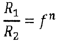
- If the fan lowers the background concentration by a factor f that was pre-characterized and remains constant over time, one obtains (eq24)

- It follows that the sensitivity of the gas-sensor can be determined by (eq25)
- Further examples: The underlying principle of the invention may further be exploited to perform a self-calibration of a
temperature sensor 3a. During a start-up phase of the sensor unit, it is assumed that TSHT = Tamb, such that system parameters, i.e. relevant parameters of heat transport such as α and β may be calibrated. - In a further embodiment, the
estimator 9 of the sensor unit ofFig. 1 is used to eliminate cross-sensitivities betweendisturbing contributions 8a-c originating fromcomponents 7a-c and thedifferent sensors 3a-c, e.g. a temperature-dependence of thetVOC sensor 3c. - Yet a further embodiment of the sensor unit comprises two
temperature sensors 3a, in particular at different locations in thechannel 2. The twotemperature sensors 3a may be influenced by contributions of thecomponent 7a in a different manner since theflow 5 advects more or less heat. This in turn may be used to make measurements of the ambient value Tamb of temperature in theambience 6 more accurate and reliable.
Claims (15)
- Sensor unit, comprising
a sensor (3) for sensing a variable of an ambient gas,
an actuator (4) for supplying the ambient gas to the sensor (3),
one or more components (7) contributing to measurement results provided by the sensor (3), and
an estimator (9) for determining an ambient value of the variable absent the contribution of the one or more components (7) dependent on a first measurement result provided by the sensor (3) in response to a first activation state of the actuator (4) and a second measurement result provided by the sensor (3) in response to a second activation state of the actuator (4) different from the first activation state. - Sensor unit according to claim 1,
wherein the estimator (9) is adapted to monitor the activation state of the actuator (3) and to accept two measurement results provided by the sensor (3) as the first and the second measurement result if a corresponding second activation state deviates from a corresponding first activation state by a minimum margin, preferably by a minimum margin in power, and
in particular wherein the estimator (9) is adapted to accept the two measurement results as the first and the second measurement result only if in addition a time interval between the corresponding first and the corresponding second measurement is less than a threshold value. - Sensor unit according to claim 1, comprising
a control unit adapted to control the actuator (4) into the first activation state and into the second activation state for conducting the first and the second measurement respectively,
in particular for controlling the actuator (4) into the first and the second activation state within a defined time interval or at defined points in time. - Sensor unit according to claim 2 or claim 3,
wherein the time interval is dimensioned such that the ambient value of the variable and the contribution of the one or more components (7) is expected to remain unchanged within the time interval or is expected to remain within a defined range within the time interval. - Sensor unit according to any of the preceding claims,
wherein the first activation state is an off state of the actuator (4) and wherein the second activation state is an on state of the actuator (4). - Sensor unit according to any of the preceding claims 1 to 4,
wherein the first activation state is a low power state of the actuator (4) and wherein the second activation state is a high power state of the actuator (4) exceeding the power consumed by the actuator (4) in the low power state. - Sensor unit according to any of the preceding claims,
wherein the actuator (4) is an actuator electrically controllable into at least the first and the second activation state,
wherein the actuator includes one or more of a fan, a pump or a loudspeaker. - Sensor unit according to any of the preceding claims,
wherein the ambient gas includes one of a gas, an aerosol or a dispersion,
in particular wherein the ambient gas is ambient air surrounding the sensor unit. - Sensor unit according to any of the preceding claims,
comprising a channel (2) with an inlet from and an outlet to the ambience (6),
wherein the sensor (3) is arranged in or at the channel (2) for sensing the variable in the ambient gas, and
wherein the actuator (4) is arranged to supply the ambient gas from the inlet through the channel (2) to the outlet thereby passing the sensor (3). - Sensor unit according to claim 8,
wherein the variable is a temperature (Tamb) of the ambient air,
wherein the sensor (3) is a temperature sensor,
wherein the one or more components (7) include an electronic component emitting heat in response to being powered. - Sensor unit according to claim 8,
wherein the variable is humidity (CH2O,amb) of the ambient air,
wherein the sensor (3) is a humidity sensor,
wherein the one more components (7) include a component releasing or absorbing humidity,
in particular wherein the one or more components (7) include an component of a housing (1) of the sensor unit. - Sensor unit according to claim 8,
wherein the variable is a gas concentration (Camb) in the ambient air,
wherein the sensor (3) is a gas sensor sensitive to the gas to be sensed,
wherein the one or more components (7) include a component releasing or absorbing the gas the sensor is sensitive to,
in particular wherein the one or more components (7) include a component of a housing (1) of the sensor unit,
in particular wherein the gas concentration is a concentration of volatile organic compounds (CtVOC,amb), and wherein the gas sensor is sensitive to the volatile organic compounds,
in particular wherein the gas sensor is a metal oxide gas sensor and wherein the estimator is configured to determine a sensitivity of the metal oxide gas sensor dependent on the first measurement result and the second measurement result. - Sensor unit according to any of the preceding claims,
wherein the estimator (9) is configured to determine the ambient value Camb of the variable absent the contribution cmat of the one or more components (7) based on a flux of the variable from the one or more components (7) to the sensor (3) equating a flux of the variable from the sensor (3) to the ambience (6), for each of the first and the second activation state of the actuator (4), and
in particular wherein the estimator (9) is configured to determine the ambient value Camb of the variable absent the contribution Cmat of the one or more components by solving the equation
- Method for determining an ambient value (Camb) of a variable in a gas in the ambience (6) of a sensor unit comprising a sensor (3) for sensing the variable, an actuator (4) for supplying the ambient gas to the sensor (3) and one or more components (7) contributing to measurement results (CSHT) provided by the sensor (3),
receiving a first measurement result (CSHT1) in response to a first activation state of the actuator (4),
receiving a second measurement result (CSHT2) in response to a second activation state of the actuator (4), and
determining the ambient value (Camb) of the variable absent the contribution (Cmat) of the one or more components (7) dependent on the first measurement result (CSHT1) and the second measurement result (CSHT2). - Computer program element comprising computer program code means for executing a method according to claim 14 when executed on a processing unit of an estimator (9).
Priority Applications (3)
| Application Number | Priority Date | Filing Date | Title |
|---|---|---|---|
| EP18208705.6A EP3660498B1 (en) | 2018-11-27 | 2018-11-27 | Ambient sensor with actuator |
| KR1020190153261A KR20200063999A (en) | 2018-11-27 | 2019-11-26 | Ambient sensor with actuator |
| CN201911179158.9A CN111220300A (en) | 2018-11-27 | 2019-11-27 | Environmental sensor with actuator |
Applications Claiming Priority (1)
| Application Number | Priority Date | Filing Date | Title |
|---|---|---|---|
| EP18208705.6A EP3660498B1 (en) | 2018-11-27 | 2018-11-27 | Ambient sensor with actuator |
Publications (2)
| Publication Number | Publication Date |
|---|---|
| EP3660498A1 true EP3660498A1 (en) | 2020-06-03 |
| EP3660498B1 EP3660498B1 (en) | 2024-08-07 |
Family
ID=64556679
Family Applications (1)
| Application Number | Title | Priority Date | Filing Date |
|---|---|---|---|
| EP18208705.6A Active EP3660498B1 (en) | 2018-11-27 | 2018-11-27 | Ambient sensor with actuator |
Country Status (3)
| Country | Link |
|---|---|
| EP (1) | EP3660498B1 (en) |
| KR (1) | KR20200063999A (en) |
| CN (1) | CN111220300A (en) |
Cited By (1)
| Publication number | Priority date | Publication date | Assignee | Title |
|---|---|---|---|---|
| WO2024020535A1 (en) * | 2022-07-22 | 2024-01-25 | VOCNomics, LLC | Method and apparatus for remote monitoring of various organic compounds |
Families Citing this family (1)
| Publication number | Priority date | Publication date | Assignee | Title |
|---|---|---|---|---|
| CN113091796B (en) * | 2021-04-06 | 2022-07-15 | 上海应用技术大学 | Sensor thermal response performance detection device |
Citations (4)
| Publication number | Priority date | Publication date | Assignee | Title |
|---|---|---|---|---|
| US20120323440A1 (en) * | 2010-02-05 | 2012-12-20 | Volvo Group North America, Llc | Method for determining ambient air temperature outside of a vehicle |
| US20140134053A1 (en) | 2012-11-14 | 2014-05-15 | Sensirion Ag | Portable electronic device with chemical sensor |
| US20140355649A1 (en) * | 2013-05-31 | 2014-12-04 | Sensirion Ag | Portable electronic device with integrated temperature sensor |
| US20180143084A1 (en) * | 2016-11-21 | 2018-05-24 | Sensirion Ag | Compensating a sensor signal |
Family Cites Families (1)
| Publication number | Priority date | Publication date | Assignee | Title |
|---|---|---|---|---|
| EP2728327B1 (en) * | 2012-11-02 | 2020-02-19 | Sensirion AG | Portable electronic device |
-
2018
- 2018-11-27 EP EP18208705.6A patent/EP3660498B1/en active Active
-
2019
- 2019-11-26 KR KR1020190153261A patent/KR20200063999A/en not_active Ceased
- 2019-11-27 CN CN201911179158.9A patent/CN111220300A/en active Pending
Patent Citations (4)
| Publication number | Priority date | Publication date | Assignee | Title |
|---|---|---|---|---|
| US20120323440A1 (en) * | 2010-02-05 | 2012-12-20 | Volvo Group North America, Llc | Method for determining ambient air temperature outside of a vehicle |
| US20140134053A1 (en) | 2012-11-14 | 2014-05-15 | Sensirion Ag | Portable electronic device with chemical sensor |
| US20140355649A1 (en) * | 2013-05-31 | 2014-12-04 | Sensirion Ag | Portable electronic device with integrated temperature sensor |
| US20180143084A1 (en) * | 2016-11-21 | 2018-05-24 | Sensirion Ag | Compensating a sensor signal |
Cited By (1)
| Publication number | Priority date | Publication date | Assignee | Title |
|---|---|---|---|---|
| WO2024020535A1 (en) * | 2022-07-22 | 2024-01-25 | VOCNomics, LLC | Method and apparatus for remote monitoring of various organic compounds |
Also Published As
| Publication number | Publication date |
|---|---|
| CN111220300A (en) | 2020-06-02 |
| KR20200063999A (en) | 2020-06-05 |
| EP3660498B1 (en) | 2024-08-07 |
Similar Documents
| Publication | Publication Date | Title |
|---|---|---|
| US9995593B2 (en) | Method for operating a sensor array | |
| CN104110319B (en) | Humidity sensor and engine system | |
| US6776817B2 (en) | Airflow sensor, system and method for detecting airflow within an air handling system | |
| US7607823B2 (en) | Leak detector comprising a self-heated thermistor control circuit | |
| US9829393B2 (en) | Method for determining the ambient temperature of a mobile device | |
| JPH07294469A (en) | Dew point or gas concentration measurement method and icing prediction device | |
| EP1859260A1 (en) | Temperature feedback control for solid state gas sensors | |
| EP3660498B1 (en) | Ambient sensor with actuator | |
| JP2007298507A (en) | Method for processing measurement values separated in time, sensor filter, gas sensor device, and method for operating gas sensor device | |
| US20030034443A1 (en) | Absolute humidity sensor to control drying equipment | |
| US20210123822A1 (en) | Detecting and indicating stability in an industrial temperature dry block calibrator | |
| WO2016111253A1 (en) | Humidity measuring device | |
| WO1997028434A1 (en) | Moisture analyzer | |
| AU2006332047B8 (en) | Linear fire-detector alarming system based on data fusion and the method | |
| US11994485B2 (en) | Method for operating a gas sensor device and gas sensor device | |
| JP5111180B2 (en) | Thermal flow meter | |
| EP0853240A2 (en) | Method of improving the selectivity of a polymer-film gas sensor and a sensor structure for implementing the method | |
| US9304098B2 (en) | Capacitive humidity sensor with hysteresis compensation | |
| JP3295894B2 (en) | Humidity sensor | |
| EP2995938A1 (en) | Integrated metal oxide chemical sensor | |
| US6112576A (en) | Gas analyzer with background gas compensation | |
| US12130251B2 (en) | Method for operating a gas sensor device and gas sensor device for ascertaining pieces of information about an air quality | |
| JP2023159874A (en) | Gas detection device and gas detection method equipped with sensor parts and oxidation parts | |
| CN114184724B (en) | Method and device for compensating carrier gas flow of chromatograph and storage medium thereof | |
| US20200263623A1 (en) | Method and device for controlling a heating element for heating a sensor element of a mass air-flow sensor for a vehicle and mass air-flow sensor system for a vehicle |
Legal Events
| Date | Code | Title | Description |
|---|---|---|---|
| PUAI | Public reference made under article 153(3) epc to a published international application that has entered the european phase |
Free format text: ORIGINAL CODE: 0009012 |
|
| STAA | Information on the status of an ep patent application or granted ep patent |
Free format text: STATUS: THE APPLICATION HAS BEEN PUBLISHED |
|
| AK | Designated contracting states |
Kind code of ref document: A1 Designated state(s): AL AT BE BG CH CY CZ DE DK EE ES FI FR GB GR HR HU IE IS IT LI LT LU LV MC MK MT NL NO PL PT RO RS SE SI SK SM TR |
|
| AX | Request for extension of the european patent |
Extension state: BA ME |
|
| STAA | Information on the status of an ep patent application or granted ep patent |
Free format text: STATUS: REQUEST FOR EXAMINATION WAS MADE |
|
| 17P | Request for examination filed |
Effective date: 20201111 |
|
| RBV | Designated contracting states (corrected) |
Designated state(s): AL AT BE BG CH CY CZ DE DK EE ES FI FR GB GR HR HU IE IS IT LI LT LU LV MC MK MT NL NO PL PT RO RS SE SI SK SM TR |
|
| STAA | Information on the status of an ep patent application or granted ep patent |
Free format text: STATUS: EXAMINATION IS IN PROGRESS |
|
| 17Q | First examination report despatched |
Effective date: 20220810 |
|
| P01 | Opt-out of the competence of the unified patent court (upc) registered |
Effective date: 20230602 |
|
| GRAP | Despatch of communication of intention to grant a patent |
Free format text: ORIGINAL CODE: EPIDOSNIGR1 |
|
| STAA | Information on the status of an ep patent application or granted ep patent |
Free format text: STATUS: GRANT OF PATENT IS INTENDED |
|
| RIC1 | Information provided on ipc code assigned before grant |
Ipc: G01N 15/06 20060101ALN20240302BHEP Ipc: G01N 33/00 20060101ALI20240302BHEP Ipc: G01N 27/12 20060101AFI20240302BHEP |
|
| INTG | Intention to grant announced |
Effective date: 20240318 |
|
| GRAS | Grant fee paid |
Free format text: ORIGINAL CODE: EPIDOSNIGR3 |
|
| GRAA | (expected) grant |
Free format text: ORIGINAL CODE: 0009210 |
|
| STAA | Information on the status of an ep patent application or granted ep patent |
Free format text: STATUS: THE PATENT HAS BEEN GRANTED |
|
| AK | Designated contracting states |
Kind code of ref document: B1 Designated state(s): AL AT BE BG CH CY CZ DE DK EE ES FI FR GB GR HR HU IE IS IT LI LT LU LV MC MK MT NL NO PL PT RO RS SE SI SK SM TR |
|
| REG | Reference to a national code |
Ref country code: GB Ref legal event code: FG4D |
|
| REG | Reference to a national code |
Ref country code: CH Ref legal event code: EP |
|
| REG | Reference to a national code |
Ref country code: IE Ref legal event code: FG4D |
|
| REG | Reference to a national code |
Ref country code: DE Ref legal event code: R096 Ref document number: 602018072692 Country of ref document: DE |
|
| REG | Reference to a national code |
Ref country code: LT Ref legal event code: MG9D |
|
| REG | Reference to a national code |
Ref country code: NL Ref legal event code: MP Effective date: 20240807 |
|
| PG25 | Lapsed in a contracting state [announced via postgrant information from national office to epo] |
Ref country code: NO Free format text: LAPSE BECAUSE OF FAILURE TO SUBMIT A TRANSLATION OF THE DESCRIPTION OR TO PAY THE FEE WITHIN THE PRESCRIBED TIME-LIMIT Effective date: 20241107 |
|
| REG | Reference to a national code |
Ref country code: AT Ref legal event code: MK05 Ref document number: 1711484 Country of ref document: AT Kind code of ref document: T Effective date: 20240807 |
|
| PG25 | Lapsed in a contracting state [announced via postgrant information from national office to epo] |
Ref country code: PT Free format text: LAPSE BECAUSE OF FAILURE TO SUBMIT A TRANSLATION OF THE DESCRIPTION OR TO PAY THE FEE WITHIN THE PRESCRIBED TIME-LIMIT Effective date: 20241209 Ref country code: NL Free format text: LAPSE BECAUSE OF FAILURE TO SUBMIT A TRANSLATION OF THE DESCRIPTION OR TO PAY THE FEE WITHIN THE PRESCRIBED TIME-LIMIT Effective date: 20240807 Ref country code: FI Free format text: LAPSE BECAUSE OF FAILURE TO SUBMIT A TRANSLATION OF THE DESCRIPTION OR TO PAY THE FEE WITHIN THE PRESCRIBED TIME-LIMIT Effective date: 20240807 Ref country code: PL Free format text: LAPSE BECAUSE OF FAILURE TO SUBMIT A TRANSLATION OF THE DESCRIPTION OR TO PAY THE FEE WITHIN THE PRESCRIBED TIME-LIMIT Effective date: 20240807 Ref country code: GR Free format text: LAPSE BECAUSE OF FAILURE TO SUBMIT A TRANSLATION OF THE DESCRIPTION OR TO PAY THE FEE WITHIN THE PRESCRIBED TIME-LIMIT Effective date: 20241108 |
|
| PG25 | Lapsed in a contracting state [announced via postgrant information from national office to epo] |
Ref country code: BG Free format text: LAPSE BECAUSE OF FAILURE TO SUBMIT A TRANSLATION OF THE DESCRIPTION OR TO PAY THE FEE WITHIN THE PRESCRIBED TIME-LIMIT Effective date: 20240807 |
|
| PG25 | Lapsed in a contracting state [announced via postgrant information from national office to epo] |
Ref country code: LV Free format text: LAPSE BECAUSE OF FAILURE TO SUBMIT A TRANSLATION OF THE DESCRIPTION OR TO PAY THE FEE WITHIN THE PRESCRIBED TIME-LIMIT Effective date: 20240807 |
|
| PG25 | Lapsed in a contracting state [announced via postgrant information from national office to epo] |
Ref country code: AT Free format text: LAPSE BECAUSE OF FAILURE TO SUBMIT A TRANSLATION OF THE DESCRIPTION OR TO PAY THE FEE WITHIN THE PRESCRIBED TIME-LIMIT Effective date: 20240807 Ref country code: IS Free format text: LAPSE BECAUSE OF FAILURE TO SUBMIT A TRANSLATION OF THE DESCRIPTION OR TO PAY THE FEE WITHIN THE PRESCRIBED TIME-LIMIT Effective date: 20241207 |
|
| PG25 | Lapsed in a contracting state [announced via postgrant information from national office to epo] |
Ref country code: HR Free format text: LAPSE BECAUSE OF FAILURE TO SUBMIT A TRANSLATION OF THE DESCRIPTION OR TO PAY THE FEE WITHIN THE PRESCRIBED TIME-LIMIT Effective date: 20240807 |
|
| PG25 | Lapsed in a contracting state [announced via postgrant information from national office to epo] |
Ref country code: ES Free format text: LAPSE BECAUSE OF FAILURE TO SUBMIT A TRANSLATION OF THE DESCRIPTION OR TO PAY THE FEE WITHIN THE PRESCRIBED TIME-LIMIT Effective date: 20240807 Ref country code: RS Free format text: LAPSE BECAUSE OF FAILURE TO SUBMIT A TRANSLATION OF THE DESCRIPTION OR TO PAY THE FEE WITHIN THE PRESCRIBED TIME-LIMIT Effective date: 20241107 |
|
| PG25 | Lapsed in a contracting state [announced via postgrant information from national office to epo] |
Ref country code: RS Free format text: LAPSE BECAUSE OF FAILURE TO SUBMIT A TRANSLATION OF THE DESCRIPTION OR TO PAY THE FEE WITHIN THE PRESCRIBED TIME-LIMIT Effective date: 20241107 Ref country code: PT Free format text: LAPSE BECAUSE OF FAILURE TO SUBMIT A TRANSLATION OF THE DESCRIPTION OR TO PAY THE FEE WITHIN THE PRESCRIBED TIME-LIMIT Effective date: 20241209 Ref country code: PL Free format text: LAPSE BECAUSE OF FAILURE TO SUBMIT A TRANSLATION OF THE DESCRIPTION OR TO PAY THE FEE WITHIN THE PRESCRIBED TIME-LIMIT Effective date: 20240807 Ref country code: NO Free format text: LAPSE BECAUSE OF FAILURE TO SUBMIT A TRANSLATION OF THE DESCRIPTION OR TO PAY THE FEE WITHIN THE PRESCRIBED TIME-LIMIT Effective date: 20241107 Ref country code: NL Free format text: LAPSE BECAUSE OF FAILURE TO SUBMIT A TRANSLATION OF THE DESCRIPTION OR TO PAY THE FEE WITHIN THE PRESCRIBED TIME-LIMIT Effective date: 20240807 Ref country code: LV Free format text: LAPSE BECAUSE OF FAILURE TO SUBMIT A TRANSLATION OF THE DESCRIPTION OR TO PAY THE FEE WITHIN THE PRESCRIBED TIME-LIMIT Effective date: 20240807 Ref country code: IS Free format text: LAPSE BECAUSE OF FAILURE TO SUBMIT A TRANSLATION OF THE DESCRIPTION OR TO PAY THE FEE WITHIN THE PRESCRIBED TIME-LIMIT Effective date: 20241207 Ref country code: HR Free format text: LAPSE BECAUSE OF FAILURE TO SUBMIT A TRANSLATION OF THE DESCRIPTION OR TO PAY THE FEE WITHIN THE PRESCRIBED TIME-LIMIT Effective date: 20240807 Ref country code: GR Free format text: LAPSE BECAUSE OF FAILURE TO SUBMIT A TRANSLATION OF THE DESCRIPTION OR TO PAY THE FEE WITHIN THE PRESCRIBED TIME-LIMIT Effective date: 20241108 Ref country code: FI Free format text: LAPSE BECAUSE OF FAILURE TO SUBMIT A TRANSLATION OF THE DESCRIPTION OR TO PAY THE FEE WITHIN THE PRESCRIBED TIME-LIMIT Effective date: 20240807 Ref country code: ES Free format text: LAPSE BECAUSE OF FAILURE TO SUBMIT A TRANSLATION OF THE DESCRIPTION OR TO PAY THE FEE WITHIN THE PRESCRIBED TIME-LIMIT Effective date: 20240807 Ref country code: BG Free format text: LAPSE BECAUSE OF FAILURE TO SUBMIT A TRANSLATION OF THE DESCRIPTION OR TO PAY THE FEE WITHIN THE PRESCRIBED TIME-LIMIT Effective date: 20240807 Ref country code: AT Free format text: LAPSE BECAUSE OF FAILURE TO SUBMIT A TRANSLATION OF THE DESCRIPTION OR TO PAY THE FEE WITHIN THE PRESCRIBED TIME-LIMIT Effective date: 20240807 |
|
| PG25 | Lapsed in a contracting state [announced via postgrant information from national office to epo] |
Ref country code: RO Free format text: LAPSE BECAUSE OF FAILURE TO SUBMIT A TRANSLATION OF THE DESCRIPTION OR TO PAY THE FEE WITHIN THE PRESCRIBED TIME-LIMIT Effective date: 20240807 Ref country code: DK Free format text: LAPSE BECAUSE OF FAILURE TO SUBMIT A TRANSLATION OF THE DESCRIPTION OR TO PAY THE FEE WITHIN THE PRESCRIBED TIME-LIMIT Effective date: 20240807 Ref country code: SM Free format text: LAPSE BECAUSE OF FAILURE TO SUBMIT A TRANSLATION OF THE DESCRIPTION OR TO PAY THE FEE WITHIN THE PRESCRIBED TIME-LIMIT Effective date: 20240807 |
|
| PG25 | Lapsed in a contracting state [announced via postgrant information from national office to epo] |
Ref country code: EE Free format text: LAPSE BECAUSE OF FAILURE TO SUBMIT A TRANSLATION OF THE DESCRIPTION OR TO PAY THE FEE WITHIN THE PRESCRIBED TIME-LIMIT Effective date: 20240807 |
|
| PG25 | Lapsed in a contracting state [announced via postgrant information from national office to epo] |
Ref country code: CZ Free format text: LAPSE BECAUSE OF FAILURE TO SUBMIT A TRANSLATION OF THE DESCRIPTION OR TO PAY THE FEE WITHIN THE PRESCRIBED TIME-LIMIT Effective date: 20240807 |
|
| PG25 | Lapsed in a contracting state [announced via postgrant information from national office to epo] |
Ref country code: SK Free format text: LAPSE BECAUSE OF FAILURE TO SUBMIT A TRANSLATION OF THE DESCRIPTION OR TO PAY THE FEE WITHIN THE PRESCRIBED TIME-LIMIT Effective date: 20240807 |
|
| REG | Reference to a national code |
Ref country code: DE Ref legal event code: R097 Ref document number: 602018072692 Country of ref document: DE |
|
| PLBE | No opposition filed within time limit |
Free format text: ORIGINAL CODE: 0009261 |
|
| STAA | Information on the status of an ep patent application or granted ep patent |
Free format text: STATUS: NO OPPOSITION FILED WITHIN TIME LIMIT |
|
| REG | Reference to a national code |
Ref country code: CH Ref legal event code: PL |
|
| PG25 | Lapsed in a contracting state [announced via postgrant information from national office to epo] |
Ref country code: MC Free format text: LAPSE BECAUSE OF FAILURE TO SUBMIT A TRANSLATION OF THE DESCRIPTION OR TO PAY THE FEE WITHIN THE PRESCRIBED TIME-LIMIT Effective date: 20240807 |
|
| PG25 | Lapsed in a contracting state [announced via postgrant information from national office to epo] |
Ref country code: LU Free format text: LAPSE BECAUSE OF NON-PAYMENT OF DUE FEES Effective date: 20241127 |
|
| REG | Reference to a national code |
Ref country code: CH Ref legal event code: PL |
|
| 26N | No opposition filed |
Effective date: 20250508 |
|
| GBPC | Gb: european patent ceased through non-payment of renewal fee |
Effective date: 20241127 |
|
| PG25 | Lapsed in a contracting state [announced via postgrant information from national office to epo] |
Ref country code: CH Free format text: LAPSE BECAUSE OF NON-PAYMENT OF DUE FEES Effective date: 20241130 |
|
| REG | Reference to a national code |
Ref country code: BE Ref legal event code: MM Effective date: 20241130 |
|
| PG25 | Lapsed in a contracting state [announced via postgrant information from national office to epo] |
Ref country code: SE Free format text: LAPSE BECAUSE OF FAILURE TO SUBMIT A TRANSLATION OF THE DESCRIPTION OR TO PAY THE FEE WITHIN THE PRESCRIBED TIME-LIMIT Effective date: 20240807 |
|
| PG25 | Lapsed in a contracting state [announced via postgrant information from national office to epo] |
Ref country code: GB Free format text: LAPSE BECAUSE OF NON-PAYMENT OF DUE FEES Effective date: 20241127 Ref country code: BE Free format text: LAPSE BECAUSE OF NON-PAYMENT OF DUE FEES Effective date: 20241130 |
|
| PG25 | Lapsed in a contracting state [announced via postgrant information from national office to epo] |
Ref country code: FR Free format text: LAPSE BECAUSE OF NON-PAYMENT OF DUE FEES Effective date: 20241130 |
|
| PG25 | Lapsed in a contracting state [announced via postgrant information from national office to epo] |
Ref country code: IE Free format text: LAPSE BECAUSE OF NON-PAYMENT OF DUE FEES Effective date: 20241127 |
|
| PGFP | Annual fee paid to national office [announced via postgrant information from national office to epo] |
Ref country code: DE Payment date: 20251118 Year of fee payment: 8 |
|
| PG25 | Lapsed in a contracting state [announced via postgrant information from national office to epo] |
Ref country code: IT Free format text: LAPSE BECAUSE OF FAILURE TO SUBMIT A TRANSLATION OF THE DESCRIPTION OR TO PAY THE FEE WITHIN THE PRESCRIBED TIME-LIMIT Effective date: 20240807 |
|
| PG25 | Lapsed in a contracting state [announced via postgrant information from national office to epo] |
Ref country code: HU Free format text: LAPSE BECAUSE OF FAILURE TO SUBMIT A TRANSLATION OF THE DESCRIPTION OR TO PAY THE FEE WITHIN THE PRESCRIBED TIME-LIMIT; INVALID AB INITIO Effective date: 20181127 |
|
| PG25 | Lapsed in a contracting state [announced via postgrant information from national office to epo] |
Ref country code: CY Free format text: LAPSE BECAUSE OF FAILURE TO SUBMIT A TRANSLATION OF THE DESCRIPTION OR TO PAY THE FEE WITHIN THE PRESCRIBED TIME-LIMIT; INVALID AB INITIO Effective date: 20181127 |