EP3660488A1 - Corrosion resistance test method and corrosion resistance test apparatus for coated metal material - Google Patents
Corrosion resistance test method and corrosion resistance test apparatus for coated metal material Download PDFInfo
- Publication number
- EP3660488A1 EP3660488A1 EP18841516.0A EP18841516A EP3660488A1 EP 3660488 A1 EP3660488 A1 EP 3660488A1 EP 18841516 A EP18841516 A EP 18841516A EP 3660488 A1 EP3660488 A1 EP 3660488A1
- Authority
- EP
- European Patent Office
- Prior art keywords
- corrosion resistance
- resistance test
- artificially damaged
- corrosion
- damaged portions
- Prior art date
- Legal status (The legal status is an assumption and is not a legal conclusion. Google has not performed a legal analysis and makes no representation as to the accuracy of the status listed.)
- Granted
Links
Images




Classifications
-
- G—PHYSICS
- G01—MEASURING; TESTING
- G01N—INVESTIGATING OR ANALYSING MATERIALS BY DETERMINING THEIR CHEMICAL OR PHYSICAL PROPERTIES
- G01N17/00—Investigating resistance of materials to the weather, to corrosion, or to light
- G01N17/02—Electrochemical measuring systems for weathering, corrosion or corrosion-protection measurement
-
- G—PHYSICS
- G01—MEASURING; TESTING
- G01N—INVESTIGATING OR ANALYSING MATERIALS BY DETERMINING THEIR CHEMICAL OR PHYSICAL PROPERTIES
- G01N17/00—Investigating resistance of materials to the weather, to corrosion, or to light
-
- G—PHYSICS
- G01—MEASURING; TESTING
- G01N—INVESTIGATING OR ANALYSING MATERIALS BY DETERMINING THEIR CHEMICAL OR PHYSICAL PROPERTIES
- G01N17/00—Investigating resistance of materials to the weather, to corrosion, or to light
- G01N17/006—Investigating resistance of materials to the weather, to corrosion, or to light of metals
Definitions
- the present invention relates to a method for a corrosion resistance test of and a corrosion resistance test apparatus for a coated metal material.
- the accelerated corrosion test such as a combined cycle test and a salt spray test has been performed.
- the accelerated corrosion test requires several months for evaluation. It is thus difficult to simply evaluate, for example, the film quality of the coating film to be coated on steel sheets made of different components or made under different baking conditions and to rapidly optimize coating conditions.
- the process control in coating factories, and the quality control relating to the rust prevention for vehicles it is desired to establish a quantitative evaluation method for rapidly and simply evaluating corrosion resistance of coated steel sheets.
- Patent Document 1 describes, as a technique for evaluating corrosion resistance of a coating applied to the surface of a metal member, a method in which a metal member having this coating and a counter electrode member are immersed in water or an electrolyte solution, the metal member is then electrically connected to a negative terminal side of a power supply for measurement, the counter electrode member is electrically connected to a positive terminal side of the power supply, and the anti-corrosive performance of the coating is evaluated on the basis of the oxygen diffusion-limited current flowing from the counter electrode member to the metal member through the coating.
- Patent Document 2 indicates that an electrode is disposed on a coating film surface side of a coated metal material via an electrolyte material, voltage is applied to between a base of the coated metal material and the surface of the coating film, and corrosion resistance of the coated metal material is evaluated on the basis of the current value at the time when electrical breakdown of the coating film occurs.
- Patent Document 3 indicates that an electrode is disposed on a coating film surface side of a coated metal material via an electrolyte material, an electrolyte material is permeated into the coating film on the coated metal material, a voltage is applied to between a base of the coated metal material and the surface of the coating film, and corrosion resistance of the coated metal material is evaluated on the basis of the value of the current flowing with application of the voltage.
- An object of the present invention is to provide a method and apparatus for the electrochemical corrosion resistance test.
- a corrosion model has been known in which metal corrosion proceeds through an anode reaction (oxidation) of generating free electrons by melting (ionizing) metal in contact with water and a cathode reaction (reduction) of generating a hydroxyl group OH - from dissolved oxygen in water by the free electrons occurred in parallel.
- an anode site and a cathode site are artificially formed in a coated metal material to accelerate corrosion.
- a method for a corrosion resistance test disclosed herein is for a coated metal material obtained by providing a metal base with a surface treatment film and includes:
- a corrosion resistance test apparatus for a coated metal material obtained by coating a metal base with a surface treatment film includes:
- one of the artificially damaged portions in the coated metal material is an anode site at which an elusion (oxidation) of metal in the metal base occurs.
- the other artificially damaged portion into which the electrons generated at the anode site flow through the metal base is a cathode site at which reduction occurs by the electrons.
- the eluted metal ions are attracted to an electrode (negative electrode) and react with dissolved oxygen in the aqueous electrolyte material or OH - generated by electrolysis of water at the electrode (negative electrode) to form iron hydroxide.
- electrode negative electrode
- electrons are supplied.
- corrosion of the coated metal material does not proceed, although metal in the metal base is ionized and a certain amount of ions are then dissolved in the aqueous electrolyte material.
- the generation of OH - at the cathode site corresponds to the cathode reaction in the corrosion model mentioned above.
- the corrosion resistance test can be said to be a reproduction of actual corrosion of the coated metal material in an accelerated manner by supplying current to the metal base through the external circuit.
- an underlayer treated surface (chemically converted surface) of the metal base is damaged by alkalization (generation of OH - .)
- adhesion of the surface treatment film is reduced (in the case of conducting no underlayer treatment, adhesion between the metal base and the surface treatment film is simply reduced), and the surface treatment film is expanded.
- hydrogen gas generated by electrolysis of water and reduction of H + accelerate the expansion of the surface treatment film. Accordingly, by examining the degree of the expansion of this surface treatment film, the corrosion progression rate of a sample in the corrosion resistance test can be determined.
- the aqueous electrolyte material any of various kinds of materials can be employed.
- the aqueous electrolyte material is a muddy material and is provided on faces of the surface treatment film at the artificially damaged portions.
- the aqueous electrolyte material if it is in a muddy state, can be provided on faces of the surface treatment film even when the surface treatment film is not flat.
- the aqueous electrolyte material can be formed into a muddy material by employing a clay mineral as an additive.
- a clay mineral a layered silicate mineral or zeolite can be employed, for example.
- the layered silicate mineral at least one selected from kaolinite, montmorillonite, sericite, illite, glauconite, chlorite, and talc can be preferably employed.
- As a supporting electrolyte (salt) at least one salt selected from sodium chloride, sodium sulfate, calcium chloride, calcium phosphate, potassium chloride, potassium nitrate, potassium hydrogen tartrate, and magnesium sulfate can be preferably employed.
- the aqueous electrolyte material may contain an organic solvent (acetone, ethanol, toluene, methanol, or the like).
- the content of the clay mineral in the aqueous electrolyte material is preferably from 1 mass% to 70 mass%.
- the content is preferably from 10 mass% to 50 mass% and more preferably from 20 mass% to 40 mass%.
- the content of the supporting electrolyte in the aqueous electrolyte material is preferably from 1 mass% to 20 mass%.
- the content is preferably from 3 mass% to 15 mass% and more preferably from 5 mass% to 10 mass%.
- the content of the organic solvent in the aqueous electrolyte material is preferably from 5% to 60% in terms of volume ratio with respect to water.
- the volume ratio is preferably from 10% to 40% and more preferably from 20% to 30%.
- electrodes at both ends of the external circuit can be buried in the aqueous electrolyte material.
- a carbon electrode, a platinum electrode, and the like can be used.
- perforated electrodes each having at least one through hole corresponding to the surface treatment film can be employed and are disposed preferably to be substantially parallel with the surface treatment film.
- each perforated electrode is formed in a ring shape having a through hole at the center thereof and is provided so that the through hole faces each artificially damaged portion.
- a mesh electrode may be employed as the perforated electrode.
- the mesh electrode may be disposed to be substantially parallel with the surface treatment film in a state in which the mesh electrode is buried in the aqueous electrolyte material.
- Each artificially damaged portion may be in any form such as a damaged portion, a puncture, or a scratch, as long as it penetrates the surface treatment film to a metal base.
- the exposed area of the metal base, formed by the artificially damaged portion is preferably from 0.005 mm 2 to 25 mm 2 , more preferably from 0.05 mm 2 to 4 mm 2 , and still more preferably from 0.13 mm 2 to 2.25 mm 2 .
- the distance between the two artificially damaged portions is preferably 2 cm or more and more preferably 3 cm or more in order to easily observe expansion of the surface treatment film at the cathode site.
- the current value is preferably from 10 ⁇ A to 10 mA, and more preferably from 100 ⁇ A to 5 mA or from 500 ⁇ A t ⁇ 2 mA.
- coated metal material suitable for applying to the corrosion resistance test examples include a coated metal material obtained by providing, as a surface treatment film, a resin coating, i.e., a coating film on a metal base.
- the metal base may be, for example, a steel material for forming an electric household appliance, a building material, or an automobile part, such as a steel plate cold commercial (SPCC), a galvanized alloy steel sheet (GA), a high-tensile strength steel sheet, or a hot stamping material, or may be a light alloy material.
- a chemical conversion coating (a phosphate coating (for example, a zinc phosphate coating), a chromate coating, or the like) may be formed on a surface of the metal base.
- the coating film includes, for example, an epoxy resin-based or acrylic resin-based cationic electrodeposition coating film (undercoat film) and may be a multilayered coating film obtained by overlaying a topcoat film on an electrodeposition coating film or by overlaying a surfacer film and a topcoat film on an electrodeposition coating film.
- undercoat film an epoxy resin-based or acrylic resin-based cationic electrodeposition coating film
- two artificially damaged portions spaced from each other in the coated metal material are electrically connected to each other by the external circuit via an aqueous electrolyte material, and current is supplied using one of the artificially damaged portions as an anode site and the other as a cathode site to proceed corrosion.
- the present corrosion resistance test can reproduce actual corrosion of the coated metal material in an accelerated manner and can evaluate corrosion resistance with high reliability.
- FIG. 1 illustrates a principle of a corrosion test.
- the reference numeral 1 denotes a coated metal material.
- a chemical conversion coating 3 is formed on a steel plate 2 serving as a metal base, and a resin coating film serving as a surface treatment film, i.e., an electrodeposition coating film 4 in the present embodiment is formed on the steel plate 2.
- Two artificially damaged portions 5 penetrating the electrodeposition coating film 4 and the chemical conversion coating 3 to the steel plate 2 are formed in the coated metal material 1 so as to be spaced from each other.
- the corrosion resistance test apparatus includes an external circuit 7 electrically connecting the two artificially damaged portions 5 in the coated metal material 1 via an aqueous electrolyte material 6 serving as a conductive material, and a direct constant current source 8 serving as a current supplier that supplies current to the steel plate 2 through the external circuit 7.
- cylindrical members 11 each having a larger diameter than each artificially damaged portion 5 are formed to be concentric with the respective artificially damaged portions 5.
- the aqueous electrolyte material 6 is placed in the cylindrical members 11 to be in contact with faces of the electrodeposition coating film 4 and enter the artificially damaged portions 5.
- Electrodes 12 are provided on both ends of the external circuit 7 and are buried in the aqueous electrolyte material 6 inside the cylindrical members 11.
- the aqueous electrolyte material 6 is a muddy material containing water, a clay mineral, and a supporting electrolyte.
- kaolinite which is a layered silicate mineral is employed as the clay mineral
- three kinds of supporting electrolyte i.e., sodium chloride, sodium sulfate, and calcium chloride, are employed as the supporting electrolyte.
- the content of the clay mineral is preferably from 1 mass% to 70 mass%
- the content of the supporting electrolyte is preferably from 1 mass% to 20 mass%.
- Each electrode 12 is a ring-shaped perforated electrode having a through hole 12a at the center thereof and is disposed to be parallel with the electrodeposition coating film 4 such that the through hole 12a faces each artificially damaged portion 5 and is concentric with the artificially damaged portion 5.
- galvanostat can be employed for example, and the current value thereof is controlled to be from 10 ⁇ A to 10 mA.
- a method for a corrosion resistance test of a coated metal material 1 using the corrosion resistance test apparatus is described in order of processes.
- Two artificially damaged portions 5 penetrating the surface treatment film (the electrodeposition coating film 4 and the chemical conversion coating 3) to the steel plate 2 are formed in the coated metal material 1 so as to be spaced from each other.
- the exposed area of the steel plate 2 by each artificially damaged portion 5 may be from 0.005 mm 2 to 25 mm 2 .
- the artificially damaged portions 5 are preferably formed by an indenter with a predetermined load using a Vickers hardness tester in order not to vary the size and depth of the artificially damaged portions 5, i.e., in order to form artificially damaged portions 5 quantitatively.
- the distance between the artificially damaged portions 5 is preferably 2 cm or more, more preferably 3 cm or more.
- the tip shape of the indenter is not limited to a quadrangular pyramid such as an indenter of the Vickers hardness tester to be described later, and various shapes having an appropriate diameter such as a spherical shape may be employed.
- Cylindrical members 11 surrounding the respective two artificially damaged portions 5 are placed on the electrodeposition coating film 4 of the coated metal material 1, and a predetermined amount of a muddy aqueous electrolyte material 6 is placed in the cylindrical members 11.
- ring-shaped perforated electrodes 12 in the external circuit 7 including a constant current source 8 are buried in the aqueous electrolyte material 6.
- the cylindrical members 11 are provided to be concentric with the respective artificially damaged portions 5.
- each perforated electrode 12 is provided to be parallel with the surface of the electrodeposition coating film 4 and to be concentric with each artificially damaged portion 5.
- the aqueous electrolyte material 6 contained in each cylindrical member 11 is in contact with the surface of the electrodeposition coating film 4 and enters each artificially damaged portion 5. Then, the artificially damaged portions are electrically connected to each other by an external circuit 7 via the aqueous electrolyte material 6 in contact with the artificially damaged portions.
- the constant current source 8 is actuated to supply current to the steel plate 2 of the coated metal material 1 through the external circuit 7 via the perforated electrodes 12, the aqueous electrolyte materials 6, and the electrodeposition coating film 4. It is preferred that the current supply is controlled so that the current will be a constant current from 10 ⁇ A t ⁇ 10 mA.
- the chemical conversion coating 3 is dissolved, and corrosion of the steel plate 2 proceeds by alkalization (generation of OH - ), and corrosion of the steel plate 2 proceeds (generation of hydrated iron oxide.)
- alkalization generation of OH -
- corrosion of the steel plate 2 proceeds (generation of hydrated iron oxide.)
- adhesion of the electrodeposition coating film 4 to the steel plate 2 is reduced.
- the generation of the hydrogen gas causes expansion of the electrodeposition coating film 4, and the corrosion of the steel plate 2 proceeds from the sites at the artificially damaged portions 5 to the periphery thereof.
- perforated electrodes 12 are disposed to surround the respective artificially damaged portions 5.
- voltage is applied to the electrodeposition coating film 4 around the artificially damaged portions 5 in a stable manner, so that the ions are efficiently transferred to the electrodeposition coating film 4, and water efficiently permeates into the electrodeposition coating film 4.
- hydrogen gas is generated in the artificially damaged portion 5 at the cathode site as described above, and this hydrogen gas passes through the through hole 12a of the perforated electrode 12.
- the aqueous electrolyte material 6 is a muddy material containing a clay mineral.
- water and ions easily permeate into the electrodeposition coating film 4 around the artificially damaged portions 5.
- the progression of corrosion at the cathode site appears as the progression of the expansion of the electrodeposition coating film 4, i.e., the increase in expanded area of the coating film. Accordingly, by observing the degree of the spread of this coating film expansion at the elapse of the predetermined time from the start of current supply, the corrosion resistance of the sample can be evaluated.
- the degree of the spread of the coating film expansion can be known by adhering an adhesive tape to the electrodeposition coating film 4 after the corrosion resistance test, peeling an expanding portion of the electrodeposition coating film 4, and measuring a diameter (hereinafter referred to as the "peeling diameter") of the exposed surface of the steel plate 2.
- the time of the corrosion resistance test for observing the spread of the coating film expansion may be, for example, from 0.5 hours to 24 hours.
- the time is, preferably from 1 hour to 10 hours, more preferably from 1 hour to 5 hours.
- FIGS. 2 and 3 Six kinds of samples (coated metal materials) which were different from each other in terms of the time for chemical conversion treatment with zinc phosphate and the baking conditions for electrodeposition coating, shown in FIGS. 2 and 3 were prepared.
- the metal base was a steel plate 2
- the electrodeposition coating film 4 had a thickness of 10 ⁇ m.
- Each sample was subjected to the present corrosion resistance test in an aspect shown in FIG. 1 .
- Two quadrangular artificially damaged portions 5 each with a diagonal length of 1 mm (each exposed area of the steel plate 2: 0.54 mm 2 ) reaching the steel plate were quantitatively formed using a Vickers hardness tester having an indenter with a quadrangular tip, i.e., formed by applying a load (test strength) of 30 kg such that the artificially damaged portions 5 are spaced 4 cm from each other.
- each artificially damaged portion 5 opened to the surface of each sample was 0.5 mm 2 corresponding to the area of the bottom surface.
- the exposed surface of the steel sheet 2 formed by each quadrangular artificially damaged portion 5 became a conical surface, and therefore, the exposed area of the steel sheet 2 was 0.54 mm 2 , which was larger than the opening area.
- aqueous electrolyte material 6 As an aqueous electrolyte material 6, a dilution obtained by diluting pseudo mud having pH 7 with a 5% saline solution (sodium chloride) to have 20% was used.
- a ring-shaped perforated electrodes (made of platinum) each with an outer diameter of about 32 mm and an inner diameter of about 30 mm were used.
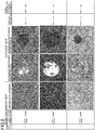
- FIGS. 2 and 3 show results of the present corrosion resistance test (appearances of the anode site, appearances of the cathode site before and after peeling, corrosion progression rates (spreading rates of coating film expansion), and the corrosion progression rates in the actual corrosion test (test in which pseudo mud was adhered to the artificial gushes and was then exposed to an environment at a temperature of 50°C and humidity of 98%)).
- the corrosion progression rate in the corrosion resistance test was lower (i.e., an increase in diameter due to spread of expansion was smaller) as the baking conditions of the electrodeposition coating film 4 became better (i.e., the baking temperature became higher or the baking time became longer), i.e., as the film quality of the electrodeposition coating film 4 became better. That is, the corrosion progression rate corresponds to the film quality of the electrodeposition coating film 4.
- the corrosion progression rates of the present corrosion resistance test was lower (i.e., an increase in diameter due to spread of expansion is smaller) in the sample 6 with a longer time for chemical conversion treatment. That is, the corrosion progression rate corresponds to the quality of the chemical conversion coating.
- the corrosion progression rate of the sample 3 with time for chemical conversion treatment of 30 seconds was lower than that of the sample 4 with time for chemical conversion treatment of 120 seconds.
- the corrosion progression rate in the actual corrosion test of the sample 3 was also lower than that of the sample 4.
- the kinds and forms of the deposits include five kinds of "water”, “5% NaCl (spray)", “5% CaCl (spray)", the “pseudo mud”, and "5% NaCl (immersion)."
- FIG. 5 indicates that the amount of water absorbed was small, and coating film expansion was barely observed even after the elapse of nine days in each of the cases of the water, the 5% NaCl (spray), and the 5% CaCl (spray).
- FIG. 6 indicates that the amount of water absorbed and the expansion occurrence rate after the elapse of nine days were considerably large in the case of the pseudo mud compared with the cases of water, the 5% NaCl (spray), and the 5% CaCl (spray).
- the cases with the same baking conditions for the electrodeposition coating film 4 at 150°C X20 mi nutes it was understood that the anount of water absorbed and the expansion occurrence rate were remarkably large in the case of the pseudo mud.
- FIG. 7 indicates that the amount of water absorbed and the expansion occurrence rate were high in the case of 5% NaCl (immersion) compared with the cases of the water, the 5% CaCl (spray), and the 5% CaCl (spray) but was considerably low compared with the case of the standard mud of FIG. 6 .
- FIG. 8 shows results of the corrosion inhibition period and the rate of water permeation into each coating film in the above-described five kinds with the same baking conditions at 150°C X20 minutes for the electrodeposition coating film 4.
- the time until the expansion occurrence rate reaches 0.5% was defined as the corrosion inhibition period.
- the rate of water permeation into the coating film was calculated on the basis of the time until the amount of water absorbed in the coating film reached 25 ⁇ g/mm 3 .
- FIG. 7 indicates that the corrosion inhibition period was short, i.e., the rate of water permeation into the coating film was considerably large in the case of the pseudo mud compared with the saline solution spray.
- a technique for supplying current to the metal base (steel plate) 2 is not limited to constant current control and may be constant voltage control.
- FIG. 9 is a plot of current supplied under the constant current control.
- FIG. 10 is a plot of current at the time when a constant voltage at which a current of about 1 mA flows is applied. In the corrosion resistance tests under the constant current control and under the constant voltage control, the test conditions other than the conditions of current supply were the same.
Landscapes
- Life Sciences & Earth Sciences (AREA)
- Biodiversity & Conservation Biology (AREA)
- Ecology (AREA)
- Environmental & Geological Engineering (AREA)
- Environmental Sciences (AREA)
- Physics & Mathematics (AREA)
- Health & Medical Sciences (AREA)
- Chemical & Material Sciences (AREA)
- Analytical Chemistry (AREA)
- Biochemistry (AREA)
- General Health & Medical Sciences (AREA)
- General Physics & Mathematics (AREA)
- Immunology (AREA)
- Pathology (AREA)
- Testing Resistance To Weather, Investigating Materials By Mechanical Methods (AREA)
Abstract
Description
- The present invention relates to a method for a corrosion resistance test of and a corrosion resistance test apparatus for a coated metal material.
- As a technique for evaluating the performance of coating films, the accelerated corrosion test such as a combined cycle test and a salt spray test has been performed.
- The accelerated corrosion test requires several months for evaluation. It is thus difficult to simply evaluate, for example, the film quality of the coating film to be coated on steel sheets made of different components or made under different baking conditions and to rapidly optimize coating conditions. Thus, in the material development, the process control in coating factories, and the quality control relating to the rust prevention for vehicles, it is desired to establish a quantitative evaluation method for rapidly and simply evaluating corrosion resistance of coated steel sheets.
- In response to the desire,
Patent Document 1 describes, as a technique for evaluating corrosion resistance of a coating applied to the surface of a metal member, a method in which a metal member having this coating and a counter electrode member are immersed in water or an electrolyte solution, the metal member is then electrically connected to a negative terminal side of a power supply for measurement, the counter electrode member is electrically connected to a positive terminal side of the power supply, and the anti-corrosive performance of the coating is evaluated on the basis of the oxygen diffusion-limited current flowing from the counter electrode member to the metal member through the coating. -
Patent Document 2 indicates that an electrode is disposed on a coating film surface side of a coated metal material via an electrolyte material, voltage is applied to between a base of the coated metal material and the surface of the coating film, and corrosion resistance of the coated metal material is evaluated on the basis of the current value at the time when electrical breakdown of the coating film occurs. -
Patent Document 3 indicates that an electrode is disposed on a coating film surface side of a coated metal material via an electrolyte material, an electrolyte material is permeated into the coating film on the coated metal material, a voltage is applied to between a base of the coated metal material and the surface of the coating film, and corrosion resistance of the coated metal material is evaluated on the basis of the value of the current flowing with application of the voltage. -
- Patent Document 1: Japanese Unexamined Patent Publication No.
2007-271501 - Patent Document 2: Japanese Unexamined Patent Publication No.
2016-50915 - Patent Document 3: Japanese Unexamined Patent Publication No.
2016-50916 - Although the corrosion resistance of the coated metal material can be evaluated by the methods for a corrosion resistance test described in Patent Documents 1-3, it is requred to establish a corrosion resistance test by which evaluation results with higher reliability can be obtained. In particular, corrosion proceeds by a damaged portion in the surface treatment film of the metal base in many cases. However, there has been no report about a simple and reliable electrochemical corrosion resistance test simulating such corrosion.
- An object of the present invention is to provide a method and apparatus for the electrochemical corrosion resistance test.
- A corrosion model has been known in which metal corrosion proceeds through an anode reaction (oxidation) of generating free electrons by melting (ionizing) metal in contact with water and a cathode reaction (reduction) of generating a hydroxyl group OH- from dissolved oxygen in water by the free electrons occurred in parallel.
- Hence, in the present invention, an anode site and a cathode site are artificially formed in a coated metal material to accelerate corrosion.
- A method for a corrosion resistance test disclosed herein is for a coated metal material obtained by providing a metal base with a surface treatment film and includes:
- forming two artificially damaged portions penetrating the surface treatment film to the metal base in the coated metal material so as to be spaced from each other;
- electrically connecting the artificially damaged portions to each other by an external circuit via an aqueous electrolyte material in contact with the artificially damaged portions; and
- supplying current to the metal base through the external circuit using one of the artificially damaged portions as an anode site and the other as a cathode site so as to proceed corrosion of the coated metal material.
- A corrosion resistance test apparatus for a coated metal material obtained by coating a metal base with a surface treatment film includes:
- an external circuit that connects two artificially damaged portions penetrating the surface treatment film to the metal base, the artificially damaged portions being formed in the coated metal material so as to be spaced from each other via an aqueous electrolyte material in contact with the artificially damaged portions; and
- a current supplier that supplies current to the metal base through the external circuit using one of the artificially damaged portions as an anode site and the other as a cathode site so as to proceed corrosion of the coated metal material.
- In the corrosion resistance test according to the above-described method or apparatus, one of the artificially damaged portions in the coated metal material is an anode site at which an elusion (oxidation) of metal in the metal base occurs. The other artificially damaged portion into which the electrons generated at the anode site flow through the metal base is a cathode site at which reduction occurs by the electrons.
- At the anode site, the eluted metal ions are attracted to an electrode (negative electrode) and react with dissolved oxygen in the aqueous electrolyte material or OH- generated by electrolysis of water at the electrode (negative electrode) to form iron hydroxide. At the anode site, electrons are supplied. Thus, due to the same principle as the electric anticorrosion, corrosion of the coated metal material does not proceed, although metal in the metal base is ionized and a certain amount of ions are then dissolved in the aqueous electrolyte material.
- On the other hand, at the cathode site, electrons flowing from the anode site via the metal base react with water and dissolved oxygen permeating in the surface treatment film and ionized H+ in water to generate hydrogen and OH-. Further, hydrogen is also generated by electrolysis of water. As a result, the pH of a portion below the surface treatment film is increased, and corrosion of the coated metal material proceeds.
- The generation of OH- at the cathode site corresponds to the cathode reaction in the corrosion model mentioned above. Thus, the corrosion resistance test can be said to be a reproduction of actual corrosion of the coated metal material in an accelerated manner by supplying current to the metal base through the external circuit.
- At the cathode site of the two artificially damaged portions, an underlayer treated surface (chemically converted surface) of the metal base is damaged by alkalization (generation of OH-.) Thus, adhesion of the surface treatment film is reduced (in the case of conducting no underlayer treatment, adhesion between the metal base and the surface treatment film is simply reduced), and the surface treatment film is expanded. Further, hydrogen gas generated by electrolysis of water and reduction of H+ accelerate the expansion of the surface treatment film. Accordingly, by examining the degree of the expansion of this surface treatment film, the corrosion progression rate of a sample in the corrosion resistance test can be determined.
- As will be described in detail later based on experimental data, since the corrosion resistance test reproduces actual corrosion in an accelerated manner as mentioned above, data of the corrosion progression rate to be obtained highly correlates with the actual corrosion progression rate. Accordingly, corrosion resistance of the sample can be evaluated with high reliability on the basis of the data of the corrosion progression rate.
- As the aqueous electrolyte material, any of various kinds of materials can be employed. In one embodiment, the aqueous electrolyte material is a muddy material and is provided on faces of the surface treatment film at the artificially damaged portions. When the aqueous electrolyte material is in a muddy state, water easily permeates into the surface treatment film at the artificially damaged portions, so that the corrosion tends to proceed. Further, the aqueous electrolyte material, if it is in a muddy state, can be provided on faces of the surface treatment film even when the surface treatment film is not flat.
- The aqueous electrolyte material can be formed into a muddy material by employing a clay mineral as an additive. As the clay mineral, a layered silicate mineral or zeolite can be employed, for example. As the layered silicate mineral, at least one selected from kaolinite, montmorillonite, sericite, illite, glauconite, chlorite, and talc can be preferably employed. As a supporting electrolyte (salt), at least one salt selected from sodium chloride, sodium sulfate, calcium chloride, calcium phosphate, potassium chloride, potassium nitrate, potassium hydrogen tartrate, and magnesium sulfate can be preferably employed. The aqueous electrolyte material may contain an organic solvent (acetone, ethanol, toluene, methanol, or the like).
- The content of the clay mineral in the aqueous electrolyte material is preferably from 1 mass% to 70 mass%. The content is preferably from 10 mass% to 50 mass% and more preferably from 20 mass% to 40 mass%.
- The content of the supporting electrolyte in the aqueous electrolyte material is preferably from 1 mass% to 20 mass%. The content is preferably from 3 mass% to 15 mass% and more preferably from 5 mass% to 10 mass%.
- The content of the organic solvent in the aqueous electrolyte material is preferably from 5% to 60% in terms of volume ratio with respect to water. The volume ratio is preferably from 10% to 40% and more preferably from 20% to 30%.
- In order to supply current to the metal base, electrodes at both ends of the external circuit can be buried in the aqueous electrolyte material. As such electrodes, a carbon electrode, a platinum electrode, and the like can be used. Specifically, perforated electrodes each having at least one through hole corresponding to the surface treatment film can be employed and are disposed preferably to be substantially parallel with the surface treatment film. For example, each perforated electrode is formed in a ring shape having a through hole at the center thereof and is provided so that the through hole faces each artificially damaged portion. Alternatively, a mesh electrode may be employed as the perforated electrode. The mesh electrode may be disposed to be substantially parallel with the surface treatment film in a state in which the mesh electrode is buried in the aqueous electrolyte material.
- Each artificially damaged portion may be in any form such as a damaged portion, a puncture, or a scratch, as long as it penetrates the surface treatment film to a metal base.
- As to the size of the artificially damaged portion at the cathode site, the smaller an exposed area of the metal base in the surface treatment film is, the lower the conductivity becomes, and the cathode reaction tends to be difficult to proceed. On the other hand, as the exposed area becomes larger, the cathode reaction becomes unstable, and the accelerated reproducibility of corrosion is deteriorated. On the basis of experiments, the exposed area of the metal base, formed by the artificially damaged portion, is preferably from 0.005 mm2 to 25 mm2, more preferably from 0.05 mm2 to 4 mm2, and still more preferably from 0.13 mm2 to 2.25 mm2.
- The distance between the two artificially damaged portions is preferably 2 cm or more and more preferably 3 cm or more in order to easily observe expansion of the surface treatment film at the cathode site.
- As to a value of the current supplied through the external circuit, as the current value becomes lower, acceleration of corrosion is deteriorated, and the time required for the test becomes longer. On the other hand, as the current value becomes higher, the corrosion reaction rate becomes unstable, and correlation with proceeding of actual corrosion is deteriorated. On the basis of experiments, the current value is preferably from 10 µA to 10 mA, and more preferably from 100 µA to 5 mA or from 500 µA
tο 2 mA. - Examples of the coated metal material suitable for applying to the corrosion resistance test include a coated metal material obtained by providing, as a surface treatment film, a resin coating, i.e., a coating film on a metal base.
- The metal base may be, for example, a steel material for forming an electric household appliance, a building material, or an automobile part, such as a steel plate cold commercial (SPCC), a galvanized alloy steel sheet (GA), a high-tensile strength steel sheet, or a hot stamping material, or may be a light alloy material. A chemical conversion coating (a phosphate coating (for example, a zinc phosphate coating), a chromate coating, or the like) may be formed on a surface of the metal base.
- The coating film includes, for example, an epoxy resin-based or acrylic resin-based cationic electrodeposition coating film (undercoat film) and may be a multilayered coating film obtained by overlaying a topcoat film on an electrodeposition coating film or by overlaying a surfacer film and a topcoat film on an electrodeposition coating film.
- In the present invention, two artificially damaged portions spaced from each other in the coated metal material are electrically connected to each other by the external circuit via an aqueous electrolyte material, and current is supplied using one of the artificially damaged portions as an anode site and the other as a cathode site to proceed corrosion. Thus, the present corrosion resistance test can reproduce actual corrosion of the coated metal material in an accelerated manner and can evaluate corrosion resistance with high reliability.
-
- [
FIG. 1] FIG. 1 is a drawing illustrating a principle of a corrosion resistance test according to the present embodiment. - [
FIG. 2] FIG. 2 is a chart indicating treatment conditions and results of corrosion resistance test ofsamples 1 to 3. - [
FIG. 3] FIG. 3 is a chart indicating treatment conditions and results of corrosion resistance test ofsamples 4 to 6. - [
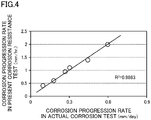
FIG. 4] FIG. 4 is a graph illustrating a correlation between the corrosion progression rate in the present corrosion resistance test and the corrosion progression rate according to the actual corrosion test. - [
FIG. 5] FIG. 5 is a chart illustrating the amount of water absorbed in a coating film and the expansion occurrence rate of the coating film in each of the cases in which the respective deposits on the coating film are water, 5% NaCl (spray), and 5% CaCl (spray). - [
FIG. 6] FIG. 6 is a chart indicating the amount of water absorbed in a coating film and the expansion occurrence rate of the coating film in the case in which a deposit on the coating film is pseudo mud. - [
FIG. 7] FIG. 7 is a chart indicating the amount of water absorbed in a coating film and the expansion occurrence rate in the case in which a deposit on the coating film is 5% NaCl (immersion). - [
FIG. 8] FIG. 8 is a graph showing the relationship between the corrosion inhibition period and the rate of water permeation into each coating film according to each deposit on the coating film. - [
FIG. 9] FIG. 9 is a plot of current under constant current supply control in the corrosion resistance test according to the embodiment. - [
FIG. 10] FIG. 10 is a plot of voltage under constant voltage supply control in the corrosion resistance test according to the embodiment. - An embodiment of the present invention will be described below with reference to the drawings. The following description of a preferred embodiment is merely illustrative in nature and is not intended to limit the present invention and applications or uses thereof.
-
FIG. 1 illustrates a principle of a corrosion test. InFIG. 1 , thereference numeral 1 denotes a coated metal material. In thecoated metal material 1 according to the present embodiment, achemical conversion coating 3 is formed on asteel plate 2 serving as a metal base, and a resin coating film serving as a surface treatment film, i.e., anelectrodeposition coating film 4 in the present embodiment is formed on thesteel plate 2. - Two artificially damaged
portions 5 penetrating theelectrodeposition coating film 4 and thechemical conversion coating 3 to thesteel plate 2 are formed in the coatedmetal material 1 so as to be spaced from each other. - The corrosion resistance test apparatus according to the present embodiment includes an external circuit 7 electrically connecting the two artificially damaged
portions 5 in the coatedmetal material 1 via anaqueous electrolyte material 6 serving as a conductive material, and a direct constantcurrent source 8 serving as a current supplier that supplies current to thesteel plate 2 through the external circuit 7. - At the two artificially damaged portions in the coated
metal material 1,cylindrical members 11 each having a larger diameter than each artificially damagedportion 5 are formed to be concentric with the respective artificially damagedportions 5. Theaqueous electrolyte material 6 is placed in thecylindrical members 11 to be in contact with faces of theelectrodeposition coating film 4 and enter the artificially damagedportions 5.Electrodes 12 are provided on both ends of the external circuit 7 and are buried in theaqueous electrolyte material 6 inside thecylindrical members 11. - The
aqueous electrolyte material 6 is a muddy material containing water, a clay mineral, and a supporting electrolyte. In the present embodiment, kaolinite which is a layered silicate mineral is employed as the clay mineral, and three kinds of supporting electrolyte, i.e., sodium chloride, sodium sulfate, and calcium chloride, are employed as the supporting electrolyte. In theaqueous electrolyte material 6, the content of the clay mineral is preferably from 1 mass% to 70 mass%, and the content of the supporting electrolyte is preferably from 1 mass% to 20 mass%. - Each
electrode 12 is a ring-shaped perforated electrode having a throughhole 12a at the center thereof and is disposed to be parallel with theelectrodeposition coating film 4 such that the throughhole 12a faces each artificially damagedportion 5 and is concentric with the artificially damagedportion 5. - As the constant
current source 8, galvanostat can be employed for example, and the current value thereof is controlled to be from 10 µA to 10 mA. - A method for a corrosion resistance test of a
coated metal material 1 using the corrosion resistance test apparatus is described in order of processes. - Two artificially damaged
portions 5 penetrating the surface treatment film (theelectrodeposition coating film 4 and the chemical conversion coating 3) to thesteel plate 2 are formed in the coatedmetal material 1 so as to be spaced from each other. The exposed area of thesteel plate 2 by each artificially damagedportion 5 may be from 0.005 mm2 to 25 mm2. There is no particular limitation on the type of the tool for forming the artificially damaged portions. For example, the artificially damagedportions 5 are preferably formed by an indenter with a predetermined load using a Vickers hardness tester in order not to vary the size and depth of the artificially damagedportions 5, i.e., in order to form artificially damagedportions 5 quantitatively. The distance between the artificially damagedportions 5 is preferably 2 cm or more, more preferably 3 cm or more. - When artificially damaged portions are formed by an indenter, the tip shape of the indenter is not limited to a quadrangular pyramid such as an indenter of the Vickers hardness tester to be described later, and various shapes having an appropriate diameter such as a spherical shape may be employed.
-
Cylindrical members 11 surrounding the respective two artificially damagedportions 5 are placed on theelectrodeposition coating film 4 of the coatedmetal material 1, and a predetermined amount of a muddyaqueous electrolyte material 6 is placed in thecylindrical members 11. At this time, ring-shapedperforated electrodes 12 in the external circuit 7 including a constantcurrent source 8 are buried in theaqueous electrolyte material 6. It is preferred that thecylindrical members 11 are provided to be concentric with the respective artificially damagedportions 5. It is preferred that eachperforated electrode 12 is provided to be parallel with the surface of theelectrodeposition coating film 4 and to be concentric with each artificially damagedportion 5. - In the above-described manner, the
aqueous electrolyte material 6 contained in eachcylindrical member 11 is in contact with the surface of theelectrodeposition coating film 4 and enters each artificially damagedportion 5. Then, the artificially damaged portions are electrically connected to each other by an external circuit 7 via theaqueous electrolyte material 6 in contact with the artificially damaged portions. - The constant
current source 8 is actuated to supply current to thesteel plate 2 of the coatedmetal material 1 through the external circuit 7 via theperforated electrodes 12, theaqueous electrolyte materials 6, and theelectrodeposition coating film 4. It is preferred that the current supply is controlled so that the current will be a constant current from 10 µA tο 10 mA. - By this current supply, electrons e- flow from the
aqueous electrolyte material 6 to thesteel plate 2 at one of the artificially damaged portions (left side inFIG. 1 ) connected to the anode side of the constantcurrent source 8. This artificially damaged portion is an anode site. The electrons e- which have flowed into thesteel sheet 2 pass through thesteel sheet 2 to the other artificially damaged portion (right side inFIG. 1 ) and is released to theaqueous electrolyte material 6 at the other artificially damaged portion. The other artificially damaged portion is a cathode site. - At the anode site, e- is supplied. Thus, due to the same principle as the electric anticorrosion, corrosion of the coated
metal material 1 does not proceed although Fe of thesteel plate 2 is ionized and then dissolved in the aqueous electrolyte material (Fe → Fe2+ + 2e-). - On the other hand, at the cathode site, electrons are transferred from the anode site. Water, dissolved oxygen, and electrons e- in the
aqueous electrolyte material 6 thus react with each other to generate OH- (H2O + 1/2O2 + 2e- → 2OH-). Further, hydrogen ions generated by ionization and electrons e- in theaqueous electrolyte material 6 react with each other to generate hydrogen (2H+ + 2e- → H2). OH- and hydrogen are generated by cathode reaction (reduction). Further, hydrogen is also generated by electrolysis of water. - At the cathode site, the
chemical conversion coating 3 is dissolved, and corrosion of thesteel plate 2 proceeds by alkalization (generation of OH-), and corrosion of thesteel plate 2 proceeds (generation of hydrated iron oxide.) Thus, adhesion of theelectrodeposition coating film 4 to thesteel plate 2 is reduced. The generation of the hydrogen gas causes expansion of theelectrodeposition coating film 4, and the corrosion of thesteel plate 2 proceeds from the sites at the artificially damagedportions 5 to the periphery thereof. - With this current supply through the external circuit 7, voltage is applied to the
aqueous electrolyte material 6 at the cathode site. Thus, cations (Na+ and the like) in theaqueous electrolyte material 6 are transferred toward thesteel plate 2 through theelectrodeposition coating film 4. Water drawn by these cations then permeates into theelectrodeposition coating film 4. At the anode site, anions (Cl- and the like) in theaqueous electrolyte material 6 are transferred toward thesteel plate 2 through theelectrodeposition coating film 4. Water drawn by these anions then permeates into theelectrodeposition coating film 4. - In particular, in the above embodiment,
perforated electrodes 12 are disposed to surround the respective artificially damagedportions 5. Thus, voltage is applied to theelectrodeposition coating film 4 around the artificially damagedportions 5 in a stable manner, so that the ions are efficiently transferred to theelectrodeposition coating film 4, and water efficiently permeates into theelectrodeposition coating film 4. In addition, hydrogen gas is generated in the artificially damagedportion 5 at the cathode site as described above, and this hydrogen gas passes through the throughhole 12a of theperforated electrode 12. Thus, deterioration of current supply performance can be avoided. - Further, the
aqueous electrolyte material 6 is a muddy material containing a clay mineral. Thus, water and ions easily permeate into theelectrodeposition coating film 4 around the artificially damagedportions 5. - Permeation of water and ions into the
electrodeposition coating film 4 around the artificially damagedportions 5 at the anode site and the cathode site is accelerated by the current supply in this manner, so that the flow state of electricity can be rapidly stable. Accordingly, progression of corrosion from the artificially damagedportion 5 at the cathode site toward the periphery thereof becomes stable. - As described above, the progression of corrosion at the cathode site appears as the progression of the expansion of the
electrodeposition coating film 4, i.e., the increase in expanded area of the coating film. Accordingly, by observing the degree of the spread of this coating film expansion at the elapse of the predetermined time from the start of current supply, the corrosion resistance of the sample can be evaluated. - The degree of the spread of the coating film expansion can be known by adhering an adhesive tape to the
electrodeposition coating film 4 after the corrosion resistance test, peeling an expanding portion of theelectrodeposition coating film 4, and measuring a diameter (hereinafter referred to as the "peeling diameter") of the exposed surface of thesteel plate 2. - The time of the corrosion resistance test for observing the spread of the coating film expansion may be, for example, from 0.5 hours to 24 hours. The time is, preferably from 1 hour to 10 hours, more preferably from 1 hour to 5 hours.
- In a case of evaluating the corrosion resistance of a sample in relation to the actual corrosion test (salt water spray test), a relationship between the corrosion progression rate in the present corrosion resistance test (an increase in diameter due to spread of the coating film expansion per unit time) and the corrosion resistance rate in the actual corrosion test is determined in advance, which makes it possible to predict how much degree of corrosion resistance in the actual corrosion test the corrosion resistance of the sample could be corresponding to.
- Six kinds of samples (coated metal materials) which were different from each other in terms of the time for chemical conversion treatment with zinc phosphate and the baking conditions for electrodeposition coating, shown in
FIGS. 2 and3 were prepared. In each of thesamples 1 to 6, the metal base was asteel plate 2, and theelectrodeposition coating film 4 had a thickness of 10 µm. Each sample was subjected to the present corrosion resistance test in an aspect shown inFIG. 1 . - Two quadrangular artificially damaged
portions 5 each with a diagonal length of 1 mm (each exposed area of the steel plate 2: 0.54 mm2) reaching the steel plate were quantitatively formed using a Vickers hardness tester having an indenter with a quadrangular tip, i.e., formed by applying a load (test strength) of 30 kg such that the artificially damagedportions 5 are spaced 4 cm from each other. - Since the area of the bottom surface of the quadrangular pyramid with a diagonal length of 1 mm was 0.5 mm2, the opening area of each artificially damaged
portion 5 opened to the surface of each sample was 0.5 mm2 corresponding to the area of the bottom surface. On the other hand, the exposed surface of thesteel sheet 2 formed by each quadrangular artificially damagedportion 5 became a conical surface, and therefore, the exposed area of thesteel sheet 2 was 0.54 mm2, which was larger than the opening area. - As an
aqueous electrolyte material 6, a dilution obtained by diluting pseudo mud having pH 7 with a 5% saline solution (sodium chloride) to have 20% was used. The composition ratio of the pseudo mud is water : kaolinite : sodium chloride : sodium sulfate : calcium chloride = 500 : 500 : 25 : 25 : 25 (by mass). - As the
electrodes 12, a ring-shaped perforated electrodes (made of platinum) each with an outer diameter of about 32 mm and an inner diameter of about 30 mm were used. - Current was supplied for 5 hours under an environment at 50°C through a constant
current source 8 set at 1 mmA. -
FIGS. 2 and3 show results of the present corrosion resistance test (appearances of the anode site, appearances of the cathode site before and after peeling, corrosion progression rates (spreading rates of coating film expansion), and the corrosion progression rates in the actual corrosion test (test in which pseudo mud was adhered to the artificial gushes and was then exposed to an environment at a temperature of 50°C and humidity of 98%)). - With reference to the
samples FIGS. 2 and3 , the corrosion progression rate in the corrosion resistance test was lower (i.e., an increase in diameter due to spread of expansion was smaller) as the baking conditions of theelectrodeposition coating film 4 became better (i.e., the baking temperature became higher or the baking time became longer), i.e., as the film quality of theelectrodeposition coating film 4 became better. That is, the corrosion progression rate corresponds to the film quality of theelectrodeposition coating film 4. - With reference to the
samples electrodeposition coating film 4 at 150°C × 20 minutes, the corrosion progression rates of the present corrosion resistance test was lower (i.e., an increase in diameter due to spread of expansion is smaller) in thesample 6 with a longer time for chemical conversion treatment. That is, the corrosion progression rate corresponds to the quality of the chemical conversion coating. - With reference to the
samples electrodeposition coating film 4 at 140°C × 20 minutes, the corrosion progression rate of thesample 3 with time for chemical conversion treatment of 30 seconds was lower than that of thesample 4 with time for chemical conversion treatment of 120 seconds. The corrosion progression rate in the actual corrosion test of thesample 3 was also lower than that of thesample 4. Thus, it was considered that there was no problem in the present corrosion resistance test, and the film quality of theelectrodeposition coating film 4 or thechemical conversion coating 3 in thesample 3 was higher than that of thesample 4 for some reasons. - As illustrated in
FIG. 4 , it was understood that the correlation between the corrosion progression rate in the present corrosion resistance test and the corrosion progression rate in the actual corrosion test in each of thesamples 1 to 6 was strong (R2 = 0.9863). It is thus demonstrated that the measurement of the corrosion progression rate by the present corrosion resistance test allows the corrosion resistance of the coatedmetal material 1 to be evaluated in a comparable manner to the actual corrosion test. - Various kinds of deposits were placed on the surfaces of various kinds of
electrodeposition coating films 4 different from each other in terms of the baking conditions or the thicknesses so as to examine the amount of water absorbed in theelectrodeposition coating film 4 and the expansion occurrence rate of theelectrodeposition coating film 4 after the elapse of nine days. As illustrated inFIGS. 5 to 7 , the kinds and forms of the deposits include five kinds of "water", "5% NaCl (spray)", "5% CaCl (spray)", the "pseudo mud", and "5% NaCl (immersion)." -
FIG. 5 indicates that the amount of water absorbed was small, and coating film expansion was barely observed even after the elapse of nine days in each of the cases of the water, the 5% NaCl (spray), and the 5% CaCl (spray). - In contrast,
FIG. 6 indicates that the amount of water absorbed and the expansion occurrence rate after the elapse of nine days were considerably large in the case of the pseudo mud compared with the cases of water, the 5% NaCl (spray), and the 5% CaCl (spray). In particular, comparing the cases with the same baking conditions for theelectrodeposition coating film 4 at 150°C X20 mi nutes, it was understood that the anount of water absorbed and the expansion occurrence rate were remarkably large in the case of the pseudo mud. -
FIG. 7 indicates that the amount of water absorbed and the expansion occurrence rate were high in the case of 5% NaCl (immersion) compared with the cases of the water, the 5% CaCl (spray), and the 5% CaCl (spray) but was considerably low compared with the case of the standard mud ofFIG. 6 . -
FIG. 8 shows results of the corrosion inhibition period and the rate of water permeation into each coating film in the above-described five kinds with the same baking conditions at 150°C X20 minutes for theelectrodeposition coating film 4. The time until the expansion occurrence rate reaches 0.5% was defined as the corrosion inhibition period. The rate of water permeation into the coating film was calculated on the basis of the time until the amount of water absorbed in the coating film reached 25 µg/mm3.FIG. 7 indicates that the corrosion inhibition period was short, i.e., the rate of water permeation into the coating film was considerably large in the case of the pseudo mud compared with the saline solution spray. - The above-described results demonstrate that if pseudo mud is employed as the
aqueous electrolyte material 6, water quickly permeates into the coating film, and the corrosion resistance test by the above-mentioned electrochemical technique can be conducted rapidly and stably. - In the corrosion resistance test according to the present embodiment, a technique for supplying current to the metal base (steel plate) 2 is not limited to constant current control and may be constant voltage control.
-
FIG. 9 is a plot of current supplied under the constant current control.FIG. 10 is a plot of current at the time when a constant voltage at which a current of about 1 mA flows is applied. In the corrosion resistance tests under the constant current control and under the constant voltage control, the test conditions other than the conditions of current supply were the same. - Under the constant current control, current values varied at the beginning of current supply but were controlled to be approximately 1 mA. Such a stabilized value of the current directly involved in the acceleration of corrosion improves the accelerated reproducibility of corrosion. That is, the corrosion resistance test becomes highly reliable.
- In contrast, under the constant voltage control, it was found that current values varied greatly, which was disadvantageous in accelerated reproducibility of corrosion. It is considered that the period from the beginning of current supply to around 7000 seconds in which the current value greatly vary corresponds to the period for permeating water into the
electrodeposition coating film 4, and water thus does not steadily permeate into the coating film, thereby greatly varying the current value. After the period, the current value still varied within the range from 0.5 mA to 1.5 mA. This may be caused by the influence of the variation in the resistance value due to the deterioration and rusting of the chemical conversion coating. - From the plot of current (waveform of current) under the constant voltage control, the proceeding state of corrosion or the degree of corrosion can be determined.
-
- 1
- Coated Metal Material
- 2
- Steel Plate (Metal Base)
- 3
- Chemical Conversion Coating
- 4
- Electrodeposition Coating Film (Surface Treatment Film)
- 5
- Artificially damaged portion
- 6
- Aqueous Electrolyte Material
- 7
- External Circuit
- 8
- Constant Current Source (Current Supplier)
- 12
- Electrode (Perforated Electrode)
- 12a
- Through Hole
Claims (12)
- A method for a corrosion resistance test of a coated metal material obtained by providing a metal base with a surface treatment film, the method comprising:forming two artificially damaged portions penetrating the surface treatment film to the metal base in the coated metal material so as to be spaced from each other;electrically connecting the artificially damaged portions to each other by an external circuit via an aqueous electrolyte material in contact with the artificially damaged portions; andsupplying current to the metal base through the external circuit using one of the artificially damaged portions as an anode site and the other as a cathode site so as to proceed corrosion of the coated metal material.
- The method of claim 1, wherein
the aqueous electrolyte material is a muddy material and is provided on faces of the surface treatment film at the respective artificially damaged portions. - The method of claim 1 or 2, wherein
an exposed area of the metal base by the artificially damaged portion at the cathode site at which a cathode reaction occurs is from 0.005 mm2 to 25 mm2. - The method of claim 3, wherein
a distance between the artificially damaged portions is 3 cm or more. - The method of any one of claims 1 to 4, wherein
a value of current supplied by the external circuit is from 10 µA to 10 mA. - The method of any one of claims 1 to 5, wherein
the surface treatment film is a resin coating film. - A corrosion resistance test apparatus for a coated metal material obtained by coating a metal base with a surface treatment film, the corrosion resistance test apparatus comprising:an external circuit that connects two artificially damaged portions penetrating the surface treatment film to the metal base, the artificially damaged portions being formed in the coated metal material so as to be spaced from each other via an aqueous electrolyte material in contact with the artificially damaged portions; anda current supplier that supplies current to the metal base through the external circuit using one of the artificially damaged portions as an anode site and the other as a cathode site so as to proceed corrosion of the coated metal material.
- The corrosion resistance test apparatus of claim 7, wherein
the aqueous electrolyte material is a muddy material and is provided on faces of the surface treatment film at the respective artificially damaged portions. - The corrosion resistance test apparatus of claim 7 or 8, wherein
an exposed area of the metal base by the artificially damaged portion at the cathode site at which a cathode reaction occurs is from 0.005 mm2 to 25 mm2. - The corrosion resistance test apparatus of claim 9, wherein
a distance between the artificially damaged portions is 3 cm or more. - The corrosion resistance test apparatus of any one of claims 7 to 10, wherein
a value of current supplied by the external circuit is from 10 µA to 10 mA. - The corrosion resistance test apparatus of any one of claims 7 to 11, wherein
the surface treatment film is a resin coating film.
Applications Claiming Priority (2)
| Application Number | Priority Date | Filing Date | Title |
|---|---|---|---|
| JP2017151600 | 2017-08-04 | ||
| PCT/JP2018/028447 WO2019026843A1 (en) | 2017-08-04 | 2018-07-30 | Corrosion resistance test method and corrosion resistance test apparatus for coated metal material |
Publications (3)
| Publication Number | Publication Date |
|---|---|
| EP3660488A1 true EP3660488A1 (en) | 2020-06-03 |
| EP3660488A4 EP3660488A4 (en) | 2020-10-07 |
| EP3660488B1 EP3660488B1 (en) | 2023-03-15 |
Family
ID=65233845
Family Applications (1)
| Application Number | Title | Priority Date | Filing Date |
|---|---|---|---|
| EP18841516.0A Active EP3660488B1 (en) | 2017-08-04 | 2018-07-30 | Corrosion resistance test method and corrosion resistance test apparatus for coated metal material |
Country Status (5)
| Country | Link |
|---|---|
| US (1) | US11519844B2 (en) |
| EP (1) | EP3660488B1 (en) |
| JP (1) | JP6784335B2 (en) |
| CN (1) | CN111033224B (en) |
| WO (1) | WO2019026843A1 (en) |
Cited By (1)
| Publication number | Priority date | Publication date | Assignee | Title |
|---|---|---|---|---|
| EP3667293B1 (en) * | 2018-12-11 | 2022-02-02 | Mazda Motor Corporation | Method of testing corrosion resistance of coated metal material |
Families Citing this family (13)
| Publication number | Priority date | Publication date | Assignee | Title |
|---|---|---|---|---|
| EP3660488B1 (en) * | 2017-08-04 | 2023-03-15 | Mazda Motor Corporation | Corrosion resistance test method and corrosion resistance test apparatus for coated metal material |
| JP7104326B2 (en) * | 2018-09-27 | 2022-07-21 | 日本電信電話株式会社 | Corrosion assessment device and its method |
| JP2020118468A (en) * | 2019-01-18 | 2020-08-06 | マツダ株式会社 | Corrosion resistance tester for coated metal materials |
| JP6733844B1 (en) * | 2020-04-15 | 2020-08-05 | マツダ株式会社 | Corrosion resistance test method for coated metal material and corrosion resistance test apparatus |
| JP6801805B1 (en) * | 2020-06-22 | 2020-12-16 | マツダ株式会社 | Measuring method and measuring device, and corrosion resistance test method and corrosion resistance test device for coated metal material |
| JP6835281B1 (en) * | 2020-06-22 | 2021-02-24 | マツダ株式会社 | Measuring method and measuring device, and corrosion resistance test method and corrosion resistance test device for coated metal material |
| JP6835280B1 (en) | 2020-06-22 | 2021-02-24 | マツダ株式会社 | Scratch treatment method and treatment equipment, and corrosion resistance test method and corrosion resistance test equipment for coated metal materials |
| JP6835279B1 (en) * | 2020-06-22 | 2021-02-24 | マツダ株式会社 | Electrode device, corrosion resistance test method for coated metal material, and corrosion resistance test device |
| JP6849140B1 (en) * | 2020-07-30 | 2021-03-24 | マツダ株式会社 | Corrosion resistance test equipment and corrosion resistance test method for coated metal materials |
| JP7156481B1 (en) * | 2021-10-01 | 2022-10-19 | マツダ株式会社 | CORROSION RESISTANCE TEST METHOD FOR COATED METAL MATERIAL, CORROSION RESISTANCE TESTING APPARATUS, CORROSION RESISTANCE TEST PROGRAM AND RECORDING MEDIUM |
| JP7088396B1 (en) * | 2021-10-01 | 2022-06-21 | マツダ株式会社 | Corrosion resistance test method, corrosion resistance test equipment, corrosion resistance test program and recording medium for coated metal materials |
| JP2024057391A (en) * | 2022-10-12 | 2024-04-24 | マツダ株式会社 | Corrosion inspection measuring equipment |
| CN116626140B (en) * | 2023-05-31 | 2025-12-19 | 寰泰储能科技股份有限公司 | Material tolerance test device and use method thereof |
Family Cites Families (40)
| Publication number | Priority date | Publication date | Assignee | Title |
|---|---|---|---|---|
| JPS55149049A (en) * | 1979-05-10 | 1980-11-20 | Nippon Paint Co Ltd | Testing method for corrosion evaluation of coated metal material and its apparatus |
| GB2048491B (en) * | 1980-03-17 | 1983-08-03 | Nippon Paint Co Ltd | Method for evaluating corrosion of coated metallic material |
| JPS5948649A (en) * | 1982-09-13 | 1984-03-19 | Nippon Paint Co Ltd | Method and apparatus for corrosion resistance evaluation of painted metal |
| US4515643A (en) * | 1982-10-22 | 1985-05-07 | Henkel Kommanditgesellschaft Auf Aktien | Method for determining and adjusting the potency and effectiveness of a metal phosphate conversion coating process |
| JPH04120453A (en) * | 1990-09-12 | 1992-04-21 | Nippon Parkerizing Co Ltd | Corrosion resistance testing method of trunk or lid of aluminum can with coating film |
| US5519330A (en) * | 1992-09-28 | 1996-05-21 | Hitachi, Ltd. | Method and apparatus for measuring degree of corrosion of metal materials |
| JPH07234202A (en) * | 1994-02-23 | 1995-09-05 | Kinki Sharyo Co Ltd | Coating adhesion test method and apparatus |
| JP3143780B2 (en) * | 1996-06-10 | 2001-03-07 | 本田技研工業株式会社 | Corrosion resistance test method and electrolysis tester for specimen consisting of metal material and coating film |
| US6365034B1 (en) * | 1997-05-07 | 2002-04-02 | Polymer Alloys Llc | High throughput electrochemical test for measuring corrosion resistance |
| JP3821004B2 (en) * | 2002-02-08 | 2006-09-13 | スズキ株式会社 | Sacrificial anode inspection method and inspection apparatus |
| US7776606B2 (en) * | 2006-03-03 | 2010-08-17 | Concurrent Technologies Corporation | Processes to create discrete corrosion defects on substrates and establish corrosion NDI test standards |
| JP2007271501A (en) | 2006-03-31 | 2007-10-18 | Osaka Gas Co Ltd | Method of evaluating corrosion protection for coating |
| FR2917519A1 (en) * | 2006-09-27 | 2008-12-19 | Peugeot Citroen Automobiles Sa | Metallic surface corrosion estimating method for motor vehicle, involves offering thickness value of thin film electrolyte as input parameter for modeling corrosion according to time and place on metallic surface |
| JP5108844B2 (en) * | 2009-05-12 | 2012-12-26 | 住友電気工業株式会社 | Corrosion test method |
| JP5238083B2 (en) * | 2009-01-02 | 2013-07-17 | イー・アイ・デュポン・ドウ・ヌムール・アンド・カンパニー | Corrosion resistance evaluation device |
| MX2013007137A (en) * | 2010-12-21 | 2013-08-01 | Coatings Foreign Ip Co Llc | Corrosion resistance evaluator. |
| US9212986B2 (en) * | 2010-12-21 | 2015-12-15 | Axalta Coating Systems Ip Co., Llc | Process of evaluating corrosion resistance |
| JP5830910B2 (en) * | 2011-04-12 | 2015-12-09 | Jfeスチール株式会社 | Method for evaluating the corrosion resistance of the contents of cans |
| JP6061393B2 (en) | 2013-09-17 | 2017-01-18 | 公益財団法人鉄道総合技術研究所 | Degradation state evaluation apparatus, deterioration state evaluation method, and deterioration state evaluation program |
| JP6213426B2 (en) * | 2014-09-02 | 2017-10-18 | マツダ株式会社 | Corrosion resistance evaluation method and corrosion resistance evaluation apparatus for painted metal |
| JP6436688B2 (en) | 2014-09-02 | 2018-12-12 | 国立大学法人広島大学 | Corrosion resistance evaluation method and corrosion resistance evaluation apparatus for painted metal |
| CN104911687A (en) * | 2015-07-07 | 2015-09-16 | 安科工程技术研究院(北京)有限公司 | Method and device for cathodic disbanding test of anticorrosive coating of buried pipeline |
| EP3660488B1 (en) * | 2017-08-04 | 2023-03-15 | Mazda Motor Corporation | Corrosion resistance test method and corrosion resistance test apparatus for coated metal material |
| JP6565979B2 (en) * | 2017-08-04 | 2019-08-28 | マツダ株式会社 | Corrosion resistance test apparatus and corrosion resistance test method for coated metal material |
| CN108548775A (en) * | 2018-04-20 | 2018-09-18 | 攀枝花学院 | Enamel coating electrode and preparation method, corrosion resistance test method |
| JP6747495B2 (en) * | 2018-12-11 | 2020-08-26 | マツダ株式会社 | Corrosion resistance test method for coated metal materials |
| JP2020118468A (en) * | 2019-01-18 | 2020-08-06 | マツダ株式会社 | Corrosion resistance tester for coated metal materials |
| CN110044810B (en) * | 2019-03-28 | 2021-12-31 | 中国船舶重工集团公司第七二五研究所 | Artificial gap device for simulating gap corrosion research under deep sea environment |
| JP6733844B1 (en) * | 2020-04-15 | 2020-08-05 | マツダ株式会社 | Corrosion resistance test method for coated metal material and corrosion resistance test apparatus |
| JP6835281B1 (en) * | 2020-06-22 | 2021-02-24 | マツダ株式会社 | Measuring method and measuring device, and corrosion resistance test method and corrosion resistance test device for coated metal material |
| JP6835280B1 (en) * | 2020-06-22 | 2021-02-24 | マツダ株式会社 | Scratch treatment method and treatment equipment, and corrosion resistance test method and corrosion resistance test equipment for coated metal materials |
| CN111879695A (en) * | 2020-06-22 | 2020-11-03 | 北京科技大学 | Real-time monitoring method for coating failure and corrosion monitoring sensor |
| JP6835279B1 (en) * | 2020-06-22 | 2021-02-24 | マツダ株式会社 | Electrode device, corrosion resistance test method for coated metal material, and corrosion resistance test device |
| JP6801805B1 (en) * | 2020-06-22 | 2020-12-16 | マツダ株式会社 | Measuring method and measuring device, and corrosion resistance test method and corrosion resistance test device for coated metal material |
| JP6849140B1 (en) * | 2020-07-30 | 2021-03-24 | マツダ株式会社 | Corrosion resistance test equipment and corrosion resistance test method for coated metal materials |
| CN112147021B (en) * | 2020-08-10 | 2022-07-29 | 中国船舶重工集团公司第七二五研究所 | Electrochemical testing device for dynamic process of metal passive film growth and degradation |
| JP6835287B1 (en) * | 2020-09-29 | 2021-02-24 | マツダ株式会社 | Corrosion resistance test method for coated metal materials and water-containing materials used in the method |
| JP6835286B1 (en) * | 2020-09-29 | 2021-02-24 | マツダ株式会社 | Corrosion resistance test method for coated metal materials and water-containing materials used in the method |
| CN113777013B (en) * | 2021-06-23 | 2023-11-21 | 武汉钢铁有限公司 | Corrosion resistance test sample and method for testing corrosion resistance of zinc-aluminum-magnesium coated steel |
| CN113588417A (en) * | 2021-06-24 | 2021-11-02 | 中国特种设备检测研究院 | Metal coating stress corrosion test method and device in corrosion environment |
-
2018
- 2018-07-30 EP EP18841516.0A patent/EP3660488B1/en active Active
- 2018-07-30 CN CN201880050709.9A patent/CN111033224B/en active Active
- 2018-07-30 WO PCT/JP2018/028447 patent/WO2019026843A1/en not_active Ceased
- 2018-07-30 US US16/635,160 patent/US11519844B2/en active Active
- 2018-07-30 JP JP2019534500A patent/JP6784335B2/en active Active
Cited By (2)
| Publication number | Priority date | Publication date | Assignee | Title |
|---|---|---|---|---|
| EP3667293B1 (en) * | 2018-12-11 | 2022-02-02 | Mazda Motor Corporation | Method of testing corrosion resistance of coated metal material |
| US11262329B2 (en) | 2018-12-11 | 2022-03-01 | Mazda Motor Corporation | Method of testing corrosion resistance of coated metal material |
Also Published As
| Publication number | Publication date |
|---|---|
| WO2019026843A1 (en) | 2019-02-07 |
| EP3660488A4 (en) | 2020-10-07 |
| JP6784335B2 (en) | 2020-11-11 |
| JPWO2019026843A1 (en) | 2020-07-09 |
| US11519844B2 (en) | 2022-12-06 |
| EP3660488B1 (en) | 2023-03-15 |
| US20210010926A1 (en) | 2021-01-14 |
| CN111033224B (en) | 2022-08-05 |
| CN111033224A (en) | 2020-04-17 |
Similar Documents
| Publication | Publication Date | Title |
|---|---|---|
| US11519844B2 (en) | Corrosion resistance test method and corrosion resistance test apparatus for coated metal material | |
| US11262329B2 (en) | Method of testing corrosion resistance of coated metal material | |
| JP6565980B2 (en) | Corrosion resistance test apparatus for coated metal material and corrosion resistance test method for coated metal material | |
| JP6515963B2 (en) | Corrosion resistance test method of coated metal material and corrosion resistance test apparatus | |
| JP6565979B2 (en) | Corrosion resistance test apparatus and corrosion resistance test method for coated metal material | |
| US11566996B2 (en) | Corrosion resistance tester for coated metal material | |
| JP6733844B1 (en) | Corrosion resistance test method for coated metal material and corrosion resistance test apparatus | |
| JP2016050916A (en) | Corrosion resistance evaluation method and corrosion resistance evaluation apparatus for painted metal | |
| JP2016099259A (en) | Evaluation method for delayed fracture characteristic of metallic material and metallic material | |
| JP6813122B2 (en) | Corrosion resistance test method for coated metal materials | |
| JP7516904B2 (en) | Corrosion resistance test method and test piece for coated metal materials | |
| JP6565665B2 (en) | Corrosion resistance evaluation method for electrical steel sheets | |
| Hosseinirad et al. | Corrosion resistance and cathodic disbondment of epoxy coating applied on zinc phosphate conversion coating containing different amounts of cobalt ions | |
| Klengel et al. | A new method for prediction of corrosion processes in metallization systems for substrates and electrical contacts | |
| Indeir et al. | Development of (AC) DC/AC Cyclic Electrochemical Corrosion Evaluation Protocols for Accelerated Testing of PVD Metallic Coatings | |
| JP2025152153A (en) | Test methods for coated metal materials | |
| Mjwana et al. | Study of Corrosion Behaviour of Carbon Steel in Evian Derived Solution from Electrochemical Techniques |
Legal Events
| Date | Code | Title | Description |
|---|---|---|---|
| STAA | Information on the status of an ep patent application or granted ep patent |
Free format text: STATUS: THE INTERNATIONAL PUBLICATION HAS BEEN MADE |
|
| PUAI | Public reference made under article 153(3) epc to a published international application that has entered the european phase |
Free format text: ORIGINAL CODE: 0009012 |
|
| STAA | Information on the status of an ep patent application or granted ep patent |
Free format text: STATUS: REQUEST FOR EXAMINATION WAS MADE |
|
| 17P | Request for examination filed |
Effective date: 20200227 |
|
| AK | Designated contracting states |
Kind code of ref document: A1 Designated state(s): AL AT BE BG CH CY CZ DE DK EE ES FI FR GB GR HR HU IE IS IT LI LT LU LV MC MK MT NL NO PL PT RO RS SE SI SK SM TR |
|
| AX | Request for extension of the european patent |
Extension state: BA ME |
|
| A4 | Supplementary search report drawn up and despatched |
Effective date: 20200903 |
|
| RIC1 | Information provided on ipc code assigned before grant |
Ipc: G01N 17/02 20060101ALI20200828BHEP Ipc: G01N 17/00 20060101AFI20200828BHEP |
|
| DAV | Request for validation of the european patent (deleted) | ||
| DAX | Request for extension of the european patent (deleted) | ||
| STAA | Information on the status of an ep patent application or granted ep patent |
Free format text: STATUS: EXAMINATION IS IN PROGRESS |
|
| 17Q | First examination report despatched |
Effective date: 20220214 |
|
| GRAP | Despatch of communication of intention to grant a patent |
Free format text: ORIGINAL CODE: EPIDOSNIGR1 |
|
| STAA | Information on the status of an ep patent application or granted ep patent |
Free format text: STATUS: GRANT OF PATENT IS INTENDED |
|
| INTG | Intention to grant announced |
Effective date: 20221212 |
|
| GRAS | Grant fee paid |
Free format text: ORIGINAL CODE: EPIDOSNIGR3 |
|
| GRAA | (expected) grant |
Free format text: ORIGINAL CODE: 0009210 |
|
| STAA | Information on the status of an ep patent application or granted ep patent |
Free format text: STATUS: THE PATENT HAS BEEN GRANTED |
|
| AK | Designated contracting states |
Kind code of ref document: B1 Designated state(s): AL AT BE BG CH CY CZ DE DK EE ES FI FR GB GR HR HU IE IS IT LI LT LU LV MC MK MT NL NO PL PT RO RS SE SI SK SM TR |
|
| REG | Reference to a national code |
Ref country code: CH Ref legal event code: EP Ref country code: GB Ref legal event code: FG4D |
|
| REG | Reference to a national code |
Ref country code: DE Ref legal event code: R096 Ref document number: 602018047312 Country of ref document: DE |
|
| REG | Reference to a national code |
Ref country code: IE Ref legal event code: FG4D |
|
| REG | Reference to a national code |
Ref country code: AT Ref legal event code: REF Ref document number: 1554274 Country of ref document: AT Kind code of ref document: T Effective date: 20230415 |
|
| REG | Reference to a national code |
Ref country code: LT Ref legal event code: MG9D |
|
| REG | Reference to a national code |
Ref country code: NL Ref legal event code: MP Effective date: 20230315 |
|
| PG25 | Lapsed in a contracting state [announced via postgrant information from national office to epo] |
Ref country code: RS Free format text: LAPSE BECAUSE OF FAILURE TO SUBMIT A TRANSLATION OF THE DESCRIPTION OR TO PAY THE FEE WITHIN THE PRESCRIBED TIME-LIMIT Effective date: 20230315 Ref country code: NO Free format text: LAPSE BECAUSE OF FAILURE TO SUBMIT A TRANSLATION OF THE DESCRIPTION OR TO PAY THE FEE WITHIN THE PRESCRIBED TIME-LIMIT Effective date: 20230615 Ref country code: LV Free format text: LAPSE BECAUSE OF FAILURE TO SUBMIT A TRANSLATION OF THE DESCRIPTION OR TO PAY THE FEE WITHIN THE PRESCRIBED TIME-LIMIT Effective date: 20230315 Ref country code: LT Free format text: LAPSE BECAUSE OF FAILURE TO SUBMIT A TRANSLATION OF THE DESCRIPTION OR TO PAY THE FEE WITHIN THE PRESCRIBED TIME-LIMIT Effective date: 20230315 Ref country code: HR Free format text: LAPSE BECAUSE OF FAILURE TO SUBMIT A TRANSLATION OF THE DESCRIPTION OR TO PAY THE FEE WITHIN THE PRESCRIBED TIME-LIMIT Effective date: 20230315 |
|
| REG | Reference to a national code |
Ref country code: AT Ref legal event code: MK05 Ref document number: 1554274 Country of ref document: AT Kind code of ref document: T Effective date: 20230315 |
|
| PG25 | Lapsed in a contracting state [announced via postgrant information from national office to epo] |
Ref country code: SE Free format text: LAPSE BECAUSE OF FAILURE TO SUBMIT A TRANSLATION OF THE DESCRIPTION OR TO PAY THE FEE WITHIN THE PRESCRIBED TIME-LIMIT Effective date: 20230315 Ref country code: NL Free format text: LAPSE BECAUSE OF FAILURE TO SUBMIT A TRANSLATION OF THE DESCRIPTION OR TO PAY THE FEE WITHIN THE PRESCRIBED TIME-LIMIT Effective date: 20230315 Ref country code: GR Free format text: LAPSE BECAUSE OF FAILURE TO SUBMIT A TRANSLATION OF THE DESCRIPTION OR TO PAY THE FEE WITHIN THE PRESCRIBED TIME-LIMIT Effective date: 20230616 Ref country code: FI Free format text: LAPSE BECAUSE OF FAILURE TO SUBMIT A TRANSLATION OF THE DESCRIPTION OR TO PAY THE FEE WITHIN THE PRESCRIBED TIME-LIMIT Effective date: 20230315 |
|
| PG25 | Lapsed in a contracting state [announced via postgrant information from national office to epo] |
Ref country code: SM Free format text: LAPSE BECAUSE OF FAILURE TO SUBMIT A TRANSLATION OF THE DESCRIPTION OR TO PAY THE FEE WITHIN THE PRESCRIBED TIME-LIMIT Effective date: 20230315 Ref country code: RO Free format text: LAPSE BECAUSE OF FAILURE TO SUBMIT A TRANSLATION OF THE DESCRIPTION OR TO PAY THE FEE WITHIN THE PRESCRIBED TIME-LIMIT Effective date: 20230315 Ref country code: PT Free format text: LAPSE BECAUSE OF FAILURE TO SUBMIT A TRANSLATION OF THE DESCRIPTION OR TO PAY THE FEE WITHIN THE PRESCRIBED TIME-LIMIT Effective date: 20230717 Ref country code: ES Free format text: LAPSE BECAUSE OF FAILURE TO SUBMIT A TRANSLATION OF THE DESCRIPTION OR TO PAY THE FEE WITHIN THE PRESCRIBED TIME-LIMIT Effective date: 20230315 Ref country code: EE Free format text: LAPSE BECAUSE OF FAILURE TO SUBMIT A TRANSLATION OF THE DESCRIPTION OR TO PAY THE FEE WITHIN THE PRESCRIBED TIME-LIMIT Effective date: 20230315 Ref country code: CZ Free format text: LAPSE BECAUSE OF FAILURE TO SUBMIT A TRANSLATION OF THE DESCRIPTION OR TO PAY THE FEE WITHIN THE PRESCRIBED TIME-LIMIT Effective date: 20230315 Ref country code: AT Free format text: LAPSE BECAUSE OF FAILURE TO SUBMIT A TRANSLATION OF THE DESCRIPTION OR TO PAY THE FEE WITHIN THE PRESCRIBED TIME-LIMIT Effective date: 20230315 |
|
| PG25 | Lapsed in a contracting state [announced via postgrant information from national office to epo] |
Ref country code: SK Free format text: LAPSE BECAUSE OF FAILURE TO SUBMIT A TRANSLATION OF THE DESCRIPTION OR TO PAY THE FEE WITHIN THE PRESCRIBED TIME-LIMIT Effective date: 20230315 Ref country code: PL Free format text: LAPSE BECAUSE OF FAILURE TO SUBMIT A TRANSLATION OF THE DESCRIPTION OR TO PAY THE FEE WITHIN THE PRESCRIBED TIME-LIMIT Effective date: 20230315 Ref country code: IS Free format text: LAPSE BECAUSE OF FAILURE TO SUBMIT A TRANSLATION OF THE DESCRIPTION OR TO PAY THE FEE WITHIN THE PRESCRIBED TIME-LIMIT Effective date: 20230715 |
|
| REG | Reference to a national code |
Ref country code: DE Ref legal event code: R097 Ref document number: 602018047312 Country of ref document: DE |
|
| PLBE | No opposition filed within time limit |
Free format text: ORIGINAL CODE: 0009261 |
|
| STAA | Information on the status of an ep patent application or granted ep patent |
Free format text: STATUS: NO OPPOSITION FILED WITHIN TIME LIMIT |
|
| PG25 | Lapsed in a contracting state [announced via postgrant information from national office to epo] |
Ref country code: SI Free format text: LAPSE BECAUSE OF FAILURE TO SUBMIT A TRANSLATION OF THE DESCRIPTION OR TO PAY THE FEE WITHIN THE PRESCRIBED TIME-LIMIT Effective date: 20230315 Ref country code: DK Free format text: LAPSE BECAUSE OF FAILURE TO SUBMIT A TRANSLATION OF THE DESCRIPTION OR TO PAY THE FEE WITHIN THE PRESCRIBED TIME-LIMIT Effective date: 20230315 |
|
| 26N | No opposition filed |
Effective date: 20231218 |
|
| PG25 | Lapsed in a contracting state [announced via postgrant information from national office to epo] |
Ref country code: MC Free format text: LAPSE BECAUSE OF FAILURE TO SUBMIT A TRANSLATION OF THE DESCRIPTION OR TO PAY THE FEE WITHIN THE PRESCRIBED TIME-LIMIT Effective date: 20230315 |
|
| PG25 | Lapsed in a contracting state [announced via postgrant information from national office to epo] |
Ref country code: MC Free format text: LAPSE BECAUSE OF FAILURE TO SUBMIT A TRANSLATION OF THE DESCRIPTION OR TO PAY THE FEE WITHIN THE PRESCRIBED TIME-LIMIT Effective date: 20230315 |
|
| REG | Reference to a national code |
Ref country code: CH Ref legal event code: PL |
|
| REG | Reference to a national code |
Ref country code: BE Ref legal event code: MM Effective date: 20230731 |
|
| PG25 | Lapsed in a contracting state [announced via postgrant information from national office to epo] |
Ref country code: LU Free format text: LAPSE BECAUSE OF NON-PAYMENT OF DUE FEES Effective date: 20230730 |
|
| GBPC | Gb: european patent ceased through non-payment of renewal fee |
Effective date: 20230730 |
|
| PG25 | Lapsed in a contracting state [announced via postgrant information from national office to epo] |
Ref country code: LU Free format text: LAPSE BECAUSE OF NON-PAYMENT OF DUE FEES Effective date: 20230730 |
|
| REG | Reference to a national code |
Ref country code: IE Ref legal event code: MM4A |
|
| PG25 | Lapsed in a contracting state [announced via postgrant information from national office to epo] |
Ref country code: GB Free format text: LAPSE BECAUSE OF NON-PAYMENT OF DUE FEES Effective date: 20230730 Ref country code: CH Free format text: LAPSE BECAUSE OF NON-PAYMENT OF DUE FEES Effective date: 20230731 |
|
| PG25 | Lapsed in a contracting state [announced via postgrant information from national office to epo] |
Ref country code: IT Free format text: LAPSE BECAUSE OF FAILURE TO SUBMIT A TRANSLATION OF THE DESCRIPTION OR TO PAY THE FEE WITHIN THE PRESCRIBED TIME-LIMIT Effective date: 20230315 Ref country code: FR Free format text: LAPSE BECAUSE OF NON-PAYMENT OF DUE FEES Effective date: 20230731 Ref country code: BE Free format text: LAPSE BECAUSE OF NON-PAYMENT OF DUE FEES Effective date: 20230731 |
|
| PG25 | Lapsed in a contracting state [announced via postgrant information from national office to epo] |
Ref country code: IE Free format text: LAPSE BECAUSE OF NON-PAYMENT OF DUE FEES Effective date: 20230730 |
|
| PG25 | Lapsed in a contracting state [announced via postgrant information from national office to epo] |
Ref country code: IE Free format text: LAPSE BECAUSE OF NON-PAYMENT OF DUE FEES Effective date: 20230730 |
|
| PG25 | Lapsed in a contracting state [announced via postgrant information from national office to epo] |
Ref country code: BG Free format text: LAPSE BECAUSE OF FAILURE TO SUBMIT A TRANSLATION OF THE DESCRIPTION OR TO PAY THE FEE WITHIN THE PRESCRIBED TIME-LIMIT Effective date: 20230315 |
|
| PG25 | Lapsed in a contracting state [announced via postgrant information from national office to epo] |
Ref country code: BG Free format text: LAPSE BECAUSE OF FAILURE TO SUBMIT A TRANSLATION OF THE DESCRIPTION OR TO PAY THE FEE WITHIN THE PRESCRIBED TIME-LIMIT Effective date: 20230315 |
|
| PG25 | Lapsed in a contracting state [announced via postgrant information from national office to epo] |
Ref country code: CY Free format text: LAPSE BECAUSE OF FAILURE TO SUBMIT A TRANSLATION OF THE DESCRIPTION OR TO PAY THE FEE WITHIN THE PRESCRIBED TIME-LIMIT; INVALID AB INITIO Effective date: 20180730 |
|
| PG25 | Lapsed in a contracting state [announced via postgrant information from national office to epo] |
Ref country code: HU Free format text: LAPSE BECAUSE OF FAILURE TO SUBMIT A TRANSLATION OF THE DESCRIPTION OR TO PAY THE FEE WITHIN THE PRESCRIBED TIME-LIMIT; INVALID AB INITIO Effective date: 20180730 |
|
| PGFP | Annual fee paid to national office [announced via postgrant information from national office to epo] |
Ref country code: DE Payment date: 20250604 Year of fee payment: 8 |
|
| PG25 | Lapsed in a contracting state [announced via postgrant information from national office to epo] |
Ref country code: TR Free format text: LAPSE BECAUSE OF FAILURE TO SUBMIT A TRANSLATION OF THE DESCRIPTION OR TO PAY THE FEE WITHIN THE PRESCRIBED TIME-LIMIT Effective date: 20230315 |