EP3660461A1 - Systeme und verfahren zur unterstützung von abweichungen auf einer integrierten flugmanagementanzeige - Google Patents
Systeme und verfahren zur unterstützung von abweichungen auf einer integrierten flugmanagementanzeige Download PDFInfo
- Publication number
- EP3660461A1 EP3660461A1 EP19211365.2A EP19211365A EP3660461A1 EP 3660461 A1 EP3660461 A1 EP 3660461A1 EP 19211365 A EP19211365 A EP 19211365A EP 3660461 A1 EP3660461 A1 EP 3660461A1
- Authority
- EP
- European Patent Office
- Prior art keywords
- flight
- deviation
- data
- aircraft
- gui
- Prior art date
- Legal status (The legal status is an assumption and is not a legal conclusion. Google has not performed a legal analysis and makes no representation as to the accuracy of the status listed.)
- Granted
Links
- 238000000034 method Methods 0.000 title claims description 69
- 230000002452 interceptive effect Effects 0.000 claims abstract description 101
- 230000008859 change Effects 0.000 claims description 40
- 230000001052 transient effect Effects 0.000 claims description 26
- 239000000446 fuel Substances 0.000 claims description 23
- 238000005065 mining Methods 0.000 claims description 7
- 238000007726 management method Methods 0.000 description 24
- 230000008569 process Effects 0.000 description 24
- 238000010586 diagram Methods 0.000 description 22
- 230000004048 modification Effects 0.000 description 17
- 238000012986 modification Methods 0.000 description 17
- 230000001149 cognitive effect Effects 0.000 description 13
- 230000000007 visual effect Effects 0.000 description 13
- 238000013459 approach Methods 0.000 description 10
- 230000006870 function Effects 0.000 description 10
- 238000004364 calculation method Methods 0.000 description 9
- 238000004891 communication Methods 0.000 description 9
- 230000003993 interaction Effects 0.000 description 9
- 238000012545 processing Methods 0.000 description 6
- 230000009471 action Effects 0.000 description 5
- 230000004913 activation Effects 0.000 description 5
- 238000006243 chemical reaction Methods 0.000 description 5
- 238000007418 data mining Methods 0.000 description 5
- 230000007423 decrease Effects 0.000 description 4
- 235000004522 Pentaglottis sempervirens Nutrition 0.000 description 3
- 230000008878 coupling Effects 0.000 description 3
- 238000010168 coupling process Methods 0.000 description 3
- 238000005859 coupling reaction Methods 0.000 description 3
- 230000001934 delay Effects 0.000 description 3
- 230000009467 reduction Effects 0.000 description 3
- 238000004458 analytical method Methods 0.000 description 2
- 238000007405 data analysis Methods 0.000 description 2
- 230000010365 information processing Effects 0.000 description 2
- 238000010801 machine learning Methods 0.000 description 2
- 238000001556 precipitation Methods 0.000 description 2
- 240000004050 Pentaglottis sempervirens Species 0.000 description 1
- 241000905137 Veronica schmidtiana Species 0.000 description 1
- 230000003213 activating effect Effects 0.000 description 1
- 230000005540 biological transmission Effects 0.000 description 1
- 230000001413 cellular effect Effects 0.000 description 1
- 238000007796 conventional method Methods 0.000 description 1
- 230000001419 dependent effect Effects 0.000 description 1
- 238000013461 design Methods 0.000 description 1
- 230000000694 effects Effects 0.000 description 1
- 238000005516 engineering process Methods 0.000 description 1
- 230000010006 flight Effects 0.000 description 1
- 238000012423 maintenance Methods 0.000 description 1
- 230000007246 mechanism Effects 0.000 description 1
- 238000012544 monitoring process Methods 0.000 description 1
- 230000008520 organization Effects 0.000 description 1
- 230000001105 regulatory effect Effects 0.000 description 1
- 238000011160 research Methods 0.000 description 1
- 230000004044 response Effects 0.000 description 1
- 238000012552 review Methods 0.000 description 1
- 231100000279 safety data Toxicity 0.000 description 1
- 238000012163 sequencing technique Methods 0.000 description 1
- 230000011664 signaling Effects 0.000 description 1
- 230000002123 temporal effect Effects 0.000 description 1
- 230000007704 transition Effects 0.000 description 1
- 238000012800 visualization Methods 0.000 description 1
Images


Classifications
-
- G—PHYSICS
- G01—MEASURING; TESTING
- G01C—MEASURING DISTANCES, LEVELS OR BEARINGS; SURVEYING; NAVIGATION; GYROSCOPIC INSTRUMENTS; PHOTOGRAMMETRY OR VIDEOGRAMMETRY
- G01C23/00—Combined instruments indicating more than one navigational value, e.g. for aircraft; Combined measuring devices for measuring two or more variables of movement, e.g. distance, speed or acceleration
- G01C23/005—Flight directors
-
- G—PHYSICS
- G08—SIGNALLING
- G08G—TRAFFIC CONTROL SYSTEMS
- G08G5/00—Traffic control systems for aircraft, e.g. air-traffic control [ATC]
- G08G5/0017—Arrangements for implementing traffic-related aircraft activities, e.g. arrangements for generating, displaying, acquiring or managing traffic information
- G08G5/0021—Arrangements for implementing traffic-related aircraft activities, e.g. arrangements for generating, displaying, acquiring or managing traffic information located in the aircraft
-
- G—PHYSICS
- G08—SIGNALLING
- G08G—TRAFFIC CONTROL SYSTEMS
- G08G5/00—Traffic control systems for aircraft, e.g. air-traffic control [ATC]
- G08G5/003—Flight plan management
- G08G5/0039—Modification of a flight plan
-
- G—PHYSICS
- G08—SIGNALLING
- G08G—TRAFFIC CONTROL SYSTEMS
- G08G5/00—Traffic control systems for aircraft, e.g. air-traffic control [ATC]
- G08G5/0047—Navigation or guidance aids for a single aircraft
- G08G5/0052—Navigation or guidance aids for a single aircraft for cruising
-
- G—PHYSICS
- G08—SIGNALLING
- G08G—TRAFFIC CONTROL SYSTEMS
- G08G5/00—Traffic control systems for aircraft, e.g. air-traffic control [ATC]
- G08G5/0073—Surveillance aids
- G08G5/0078—Surveillance aids for monitoring traffic from the aircraft
-
- G—PHYSICS
- G08—SIGNALLING
- G08G—TRAFFIC CONTROL SYSTEMS
- G08G5/00—Traffic control systems for aircraft, e.g. air-traffic control [ATC]
- G08G5/0073—Surveillance aids
- G08G5/0091—Surveillance aids for monitoring atmospheric conditions
Definitions
- Embodiments of the subject matter described herein relate generally to interactive aircraft display functionality. More particularly, embodiments of the subject matter relate to time-based, integrated aircraft display functionality that enables user interaction with and awareness of multiple data sources from a display onboard an aircraft.
- pilot workload is often high, requiring the performance of multiple simultaneous tasks.
- the flight crew uses several systems onboard an aircraft and may be required to direct their gaze in multiple directions to complete necessary tasks, obtain required information, and maintain safe and effective operation of the aircraft. Directing the gaze of a single pilot toward one particular system has an opportunity cost in terms of information processing in flight operations, an inability to attend and glean flight critical information from other displays or instrumentation.
- the management of information, tasks, time, and flight path are all performed by the skill of two pilots in most flight operations, and a significant reduction in pilot workload is needed to enable single pilot operations, an emerging industry interest given advances in automation and changes in pilot demographics and availability.
- a flight deck system for providing task management assistance in managing the flight path to the flight crew comprises one or more processors configured by programming instructions on non-transient computer readable media.
- the system is configured to: mine flight plan data for a current flight plan, navigational data, and vertical situation display (VSD) data from one or more aircraft systems; obtain notification data items originating from onboard avionics systems and from systems external to onboard avionics systems that indicate upcoming conditions that will affect the current flight plan; automatically analyze the mined flight plan data and the notification data items to identify a sensed deviation condition; automatically identify an aircraft-related deviation condition from an aircraft failure event; receive flight crew notification of a non-sensed deviation condition; automatically determine one or more modifications to the current flight plan to generate a plurality of flight plan deviation options to accommodate a sensed deviation condition, an aircraft-related deviation condition, or a non-sensed deviation condition; and present graphical elements representative of the flight plan deviation options to the flight crew on an integrated interactive graphical user interface (GUI) comprising a timeline GUI,
- GUI
- a method in a flight deck system for providing task management assistance in managing the flight path to the flight crew comprises: mining flight plan data for a current flight plan, navigational data, and vertical situation display (VSD) data from one or more aircraft systems; obtaining notification data items originating from onboard avionics systems and from systems external to onboard avionics systems that indicate upcoming conditions that will affect the current flight plan; automatically analyzing the mined flight plan data and the notification data items to identify a sensed deviation condition when a sensed deviation condition exists; automatically identifying an aircraft-related deviation condition from an aircraft failure event when an aircraft failure event exists; receiving flight crew notification of a non-sensed deviation condition when a non-sensed deviation condition exists; automatically determining one or more modifications to the current flight plan to generate a plurality of flight plan deviation options to accommodate a sensed deviation condition, an aircraft-related deviation condition, or a non-sensed deviation condition; and presenting graphical elements representative of the flight plan deviation options to the flight crew on an integrated interactive graphical user interface (GU
- module refers to any hardware, software, firmware, electronic control component, processing logic, and/or processor device, individually or in any combination, including without limitation: application specific integrated circuit (ASIC), a field-programmable gate-array (FPGA), an electronic circuit, a processor (shared, dedicated, or group) and memory that executes one or more software or firmware programs, a combinational logic circuit, and/or other suitable components that provide the described functionality.
- ASIC application specific integrated circuit
- FPGA field-programmable gate-array
- processor shared, dedicated, or group
- memory executes one or more software or firmware programs, a combinational logic circuit, and/or other suitable components that provide the described functionality.
- Embodiments of the present disclosure may be described herein in terms of functional and/or logical block components and various processing steps. It should be appreciated that such block components may be realized by any number of hardware, software, and/or firmware components configured to perform the specified functions. For example, an embodiment of the present disclosure may employ various integrated circuit components, e.g., memory elements, digital signal processing elements, logic elements, look-up tables, or the like, which may carry out a variety of functions under the control of one or more microprocessors or other control devices. In addition, those skilled in the art will appreciate that embodiments of the present disclosure may be practiced in conjunction with any number of systems, and that the systems described herein is merely exemplary embodiments of the present disclosure.
- the subject matter described herein discloses apparatus, systems, techniques and articles for an integrated pilot workflow management system.
- the integrated pilot workflow management system can reduce flight crew workload associated with managing information, operational tasks, time, and flight path management.
- a significant reduction in flight crew workload can help enable single pilot operations and the system can contribute to workload reduction by presenting tasks and information in the proper context, timing, and sequence.
- the described apparatus, systems, techniques and articles can support the flight crew by acquiring information, integrating the acquired information into a workflow, and presenting the acquired information in a useful format.
- the described apparatus, systems, techniques and articles can access onboard data sources and offboard information that are filtered for the planned flight.
- the described apparatus, systems, techniques and articles can present notifications and alerts as they arise in the workflow, including updates relevant to the planned route of flight, destination and alternate airports.
- the described apparatus, systems, techniques and articles can support pilot workflow by sequencing tasks such as checklists, briefings, fuel tracking, notifications, and information in the context of the flight plan.
- the described apparatus, systems, techniques and articles may also allow the flight crew to annotate the flight plan with personalized notes and reminders.
- the described apparatus, systems, techniques and articles can assist the flight crew with managing interruptions and distractions, tasks, information, and unexpected events.
- the described apparatus, systems, techniques and articles can support the flight crew when recovering from interruptions and distractions by keeping place in the tasking, issuing reminders to resume tasks when necessary, and enabling the flight crew to flexibly shift tasks as needed.
- the described apparatus, systems, techniques and articles can provide a visual timeline that, in addition to providing a waypoint list, can list operational tasks that may include: icons for accessing normal checklists; icons for accessing phase of flight transition briefings; icons for accessing SPO (single pilot operation) return to duty situational awareness briefing; aircraft configuration change points; altitude change points; operational constraints (RTA, altitude, speed); current and projected aircraft energy and trajectory; position reporting points; ATC communications; and FIR boundaries.
- operational tasks may include: icons for accessing normal checklists; icons for accessing phase of flight transition briefings; icons for accessing SPO (single pilot operation) return to duty situational awareness briefing; aircraft configuration change points; altitude change points; operational constraints (RTA, altitude, speed); current and projected aircraft energy and trajectory; position reporting points; ATC communications; and FIR boundaries.
- the described apparatus, systems, techniques and articles can allow the flight crew to interact via multi-modal interaction (e.g ., touch, speech, cursor).
- the described apparatus, systems, techniques and articles can use natural language speech to enable the flight crew to issue simple commands.
- the described apparatus, systems, techniques and articles may use FMS generated flight plan data to build a visual way point list from the computed flight plan and build a workflow manager where information, tasks, and functions are enabled in the context of the flight plan.
- the described apparatus, systems, techniques and articles can present normal checklists at the time and flight phase in which they are needed and allow the flight crew to access them via icons on the timeline.
- the described apparatus, systems, techniques and articles can allow operational information such as ATIS, significant weather, and NOTAMS to be retrieved from connected sources and be represented on the timeline at the time needed by the flight crew for review.
- the flight crew may access difficult to find information regarding the flight directly on the timeline, such as remaining fuel and maximum achievable altitude.
- the described apparatus, systems, techniques and articles can present direct to, lateral, and vertical flight plan deviations on a navigation display as a visual layer on top of navigation data.
- FIG. 1 is a diagram of an example system 100 onboard an aircraft for providing integrative interactive display data for flight planning and aircraft onboard interactions to streamline flight crew workload.
- the system 100 operates to provide a user-friendly and central display presentation of a time-based flight plan, user-selectable icons that provide time-based notifications during performance of a mission, a combination of display aspects that include an aircraft flight plan timeline, a map display from which a user may toggle between three-dimensional (3D) views and bird's-eye views, and deviation assistance capabilities that identify conditions requiring an aircraft to divert and provide candidate flight plan modifications from which a new flight plan may be selected or automatically generated.
- 3D three-dimensional
- the example system 100 includes a computing device 102 that communicates with one or more avionics systems 104 onboard an aircraft (including a Flight Management System (FMS) 106, a display device 108, and at least one remote server system 110.
- FMS Flight Management System
- a display device 108 includes a display device 108 and at least one remote server system 110.
- certain embodiments of the system 100 may include additional or alternative elements and components, as desired for the particular application.
- the example computing device 102 may be implemented by any computing device that includes at least one processor, some form of memory hardware, a user interface, and communication hardware.
- the computing device 102 may be implemented using a personal computing device, such as a tablet computer, a laptop computer, a personal digital assistant (PDA), a smartphone, or the like.
- the computing device 102 is capable of storing, maintaining, and executing an Electronic Flight Bag (EFB) application configured to determine and present flight data analysis, including flight planning, flight plan deviation analysis, flight plan timeline data, flight plan notification data, navigation data, map data, aviation checklist data, weather data, or the like.
- EFB Electronic Flight Bag
- the computing device 102 is configured to implement a flight deck system 112 for providing navigational guidance to the flight crew.
- the example flight deck system 112 comprises one or more processors configured by programming instructions on non-transient computer readable media.
- the example flight deck system 112 is configured to establish communications with the FMS 106 to obtain FMS-based flight planning data for use via the cockpit display 108.
- the aircraft 106 may be any aviation vehicle for which the integrated interactive display functionality is relevant and applicable during flight planning and completion of a flight route.
- the aircraft 106 may be implemented as an airplane, helicopter, spacecraft, hovercraft, or the like.
- the one or more avionics systems 108 may include a Flight Management System (FMS), Automatic Dependent Surveillance - Broadcast (ADS-B) devices, Terrain Awareness and Warning System (TAWS) devices, navigation devices, weather radar, brake systems, or the like.
- Data obtained from the one or more avionics systems 108 may include, without limitation: flight plan data, current and updated flight parameter data, weather data, airport data, runway analysis data, aircraft performance data, navigation data, map data, or the like.
- the server system 110 may include any number of application servers, and each server may be implemented using any suitable computer. In some embodiments, the server system 110 includes one or more dedicated computers. In some embodiments, the server system 110 includes one or more computers carrying out other functionality in addition to server operations. Each server of the server system 110 may be maintained by any applicable business or organization (e.g ., government and regulatory agencies, universities and other research-based organizations, airlines, aviation safety monitoring organizations, safety data aggregators, weather data aggregators, traffic data aggregators), and each server of the server system 110 may store and provide any type of data used to perform flight data analysis.
- any applicable business or organization e.g ., government and regulatory agencies, universities and other research-based organizations, airlines, aviation safety monitoring organizations, safety data aggregators, weather data aggregators, traffic data aggregators
- each server of the server system 110 may store and provide any type of data used to perform flight data analysis.
- Such data may include, without limitation: weather data (e.g ., wind speed, cloud cover, visibility, precipitation, temperature); airport and air traffic control (ATC) data (e.g., airport, runway length, ATIS, airport arrival rate, arrival/departure taxi time); Automatic Terminal Information Service (ATIS) data (e.g ., current weather data, active runways, available approaches, Notices to Airmen (NOTAMs)); aircraft and flight-specific data (e.g., flight state data), flight plan data, aircraft condition data, aircraft specifications, NOTAMs).
- Exemplary embodiments of the server system 110 may include weather services, operations and performance data services (e.g ., the Federal Aviation Administration System Wide Information Management, archived data, and/or current data), or the like.
- the flight deck system 112 communicates with an onboard FMS to obtain relevant flight planning and timing data associated with the current flight plan.
- the flight deck system 112 also obtains connected data associated with airport data, runway data, navigation data, map data, weather data, waypoint data, aviation checklist data, aircraft data, aircraft weight data, aircraft fuel data, timing data, distance data, airport facilities data, emergency services data, legality data, flight plan deviation data, and the like, from the one or more remote servers of the server system 110.
- the flight deck system 112 uses the relevant data to: (1) present an interactive timeline including a waypoint list and corresponding timing data for the aircraft to reach each waypoint, and including user-selectable icons representing alerts/notifications, user-configured reminders, and/or checklists associated with particular times and corresponding locations on the timeline; (2) present a navigation/map display including color-coded graphical elements to emphasize an active segment of a current flight path and toggle-functionality for toggling between a three-dimensional graphical display of a current location of the aircraft and current surroundings (as associated with the current flight plan) and a top-down, "bird's eye view” graphical display of the current location of the aircraft and current surroundings; (3) present smart checklist functionality including guiding flight crew members through checklist tasks/items based on previously submitted user input, wherein each checklist input item indicates a next item for presentation from an aggregate set of checklist data that includes a plurality of checklists and each of the plurality of checklists includes a plurality of checklist tasks, and also presenting non-normal checklist items as
- the example flight deck system is configured to: mine flight plan data, navigational data, and vertical situation display (VSD) data from one or more aircraft systems, the mined flight plan data including a plurality of waypoints and other course data items for a current flight plan, the mined navigational data comprising aircraft location, speed, and heading data, the mined VSD data comprising a vertical profile of the aircraft for the current flight plan, an altitude reference, terrain data, and glideslope data; obtain notification data items originating from systems external to the aircraft that indicate upcoming conditions that will affect the aircraft flight plan and a location at which the upcoming conditions will affect the aircraft flight plan; determine an estimated flight time to reach each of the plurality of waypoints, course data items, and the upcoming conditions; cause an integrated interactive graphical user interface (GUI) comprising a timeline GUI, a map GUI, and a VSD GUI to be displayed on an aircraft display, wherein the timeline GUI is configured to display a timeline with a time scale, waypoint graphical elements representative of the waypoints, course data item graphical
- FIG. 2A is a block diagram of example hardware components in an example computer system 200 that may implement a flight deck system for providing task management assistance in managing the flight path to the flight crew.
- the example functional components of the example computer system 200 include: at least one processor 202; system memory 204; a user interface 206; a communication device 208; and a display device 210.
- the elements and features of the example computer system 200 of FIG. 2A may be operatively associated with one another, coupled to one another, or otherwise configured to cooperate with one another as needed to support the desired functionality, as described herein. For ease of illustration and clarity, the various physical, electrical, and logical couplings and interconnections for these elements and features are not depicted in FIG. 2A . Moreover, embodiments of the example computer system 200 may also include other elements, modules, and features that cooperate to support the desired functionality. For simplicity, FIG. 2A only depicts certain elements that relate to the interactive integrated display creation and use techniques described in more detail below.
- the at least one processor 202 may be implemented or performed with one or more general purpose processors, a content addressable memory, a digital signal processor, an application specific integrated circuit, a field programmable gate array, any suitable programmable logic device, discrete gate or transistor logic, discrete hardware components, or any combination designed to perform the functions described here.
- the at least one processor 202 may be realized as one or more microprocessors, controllers, microcontrollers, or state machines.
- the at least one processor 202 may be implemented as a combination of computing devices, e.g., a combination of digital signal processors and microprocessors, a plurality of microprocessors, one or more microprocessors in conjunction with a digital signal processor core, or any other such configuration.
- the at least one processor 202 is communicatively coupled to the system memory 204.
- the system memory 204 is configured to store any obtained or generated data associated with the interactive integrated display, including flight planning, flight deviation options, flight plan timelines, flight plan waypoints, navigation data, map data, VSD data, notification and alerting data, aviation checklist data, or the like.
- the system memory 204 may be realized using any number of devices, components, or modules, as appropriate to the embodiment.
- the computing device 200 could include system memory 204 integrated therein and/or a system memory 204 operatively coupled thereto, as appropriate to the particular embodiment.
- system memory 204 could be realized as RAM memory, flash memory, EPROM memory, EEPROM memory, registers, a hard disk, a removable disk, or any other form of storage medium known in the art.
- the system memory 204 includes a hard disk, which may also be used to support functions of the computing device 200.
- the system memory 204 can be coupled to the at least one processor 202 such that the at least one processor 202 can read information from, and write information to, the system memory 204.
- the system memory 204 may be integral to the at least one processor 202.
- the at least one processor 202 and the system memory 204 may reside in a suitably designed application-specific integrated circuit (ASIC).
- ASIC application-specific integrated circuit
- the user interface 206 may include or cooperate with various features to allow a user to interact with the computer system 200. Accordingly, the user interface 206 may include various human-to-machine interfaces, e.g ., a keypad, keys, a keyboard, buttons, switches, knobs, a touchpad, a joystick, a pointing device, a virtual writing tablet, a touch screen, a microphone, or any device, component, or function that enables the user to select options, input information, or otherwise control the operation of the computer system 200.
- various human-to-machine interfaces e.g ., a keypad, keys, a keyboard, buttons, switches, knobs, a touchpad, a joystick, a pointing device, a virtual writing tablet, a touch screen, a microphone, or any device, component, or function that enables the user to select options, input information, or otherwise control the operation of the computer system 200.
- the user interface 206 could be manipulated by an operator to provide user input checklist completion data, to provide user-configured reminder data to initialize a user-configured reminder icon on the timeline display, and/or to provide user selections for flight plan deviation options presented via the map/navigation display, as described herein.
- the user interface 206 may implement multi-modal functionality that includes voice data and/or speech data recognition, touch interaction, gesture interaction, and/or cursor interaction.
- the user interface 206 may include or cooperate with various features to allow a user to interact with the computer system 200 via graphical elements rendered on a display element (e.g ., the display device 210). Accordingly, the user interface 206 may initiate the creation, maintenance, and presentation of a graphical user interface (GUI) for the integrated interactive display or any one of the component parts of the integrated interactive display (e.g., a timeline graphical element, a map/navigational display graphical element, a vertical situation display (VSD) graphical element).
- GUI graphical user interface
- the display device 210 implements touch-sensitive technology for purposes of interacting with the GUI. Thus, a user can manipulate the GUI by moving a cursor symbol rendered on the display device 210, or by physically interacting with the display device 210 itself for recognition and interpretation, via the user interface 206.
- the communication device 208 is suitably configured to communicate data between the computer system 200 and one or more remote servers, one or more secondary computing devices, and one or more avionics systems onboard an aircraft.
- the communication device 208 may transmit and receive communications over a wireless local area network (WLAN), the Internet, a satellite uplink/downlink, a cellular network, a broadband network, a wide area network, or the like.
- WLAN wireless local area network
- the Internet a satellite uplink/downlink
- a cellular network a cellular network
- broadband network a wide area network, or the like.
- Data received by the communication device 208 may include, without limitation: weather data, airport data, runway data, air traffic control (ATC) data, airport arrival delays, airport departure delays, "hold” notifications and/or holding patterns associated with particular waypoints, Automatic Terminal Information Service (ATIS) data (e.g ., current weather data, active runways, available approaches, Notices to Airmen (NOTAMs)); aircraft and flight-specific data (e.g., flight state data, flight plan data, aircraft specifications, NOTAMs).
- Data provided by the communication device 208 may include, without limitation: flight plan clearance requests associated with flight plan deviation options, requests for external data accessible via remotely located servers, or the like.
- the display device 210 is configured to display various icons, text, and/or graphical elements associated with the integrated interactive display, including graphical elements and text associated with flight planning, flight plan timing, notifications/alerts associated with flight plan and timing of the flight plan, aviation checklists for completion during the flight (including normal and non-normal "smart" checklists), and the like.
- the display device 210 is communicatively coupled to the user interface 206 and at least one processor 202.
- the at least one processor 202, the user interface 206, and the display device 210 are cooperatively configured to display, render, or otherwise convey one or more graphical representations or images associated with the interactive integrated display and associated functionality on the display device 210, as described in greater detail below.
- the display device 210 is realized as an electronic display configured to graphically present the integrated interactive display, as described herein.
- the computer system 200 is an integrated computer system onboard an aircraft, and the display device 210 is located within a cockpit of the aircraft, and is thus implemented as an aircraft display.
- the display device 210 is implemented as a display screen of a standalone, personal computing device (e.g ., laptop computer, tablet computer). It will be appreciated that although the display device 210 may be implemented using a single display, certain embodiments may use additional displays ( i.e., a plurality of displays) to accomplish the functionality of the display device 210 described herein.
- FIG. 2B is a functional block diagram of functional components of the example computer system 200 that are implemented via the example hardware components of FIG. 2A .
- the functional components of the example computer system 200 includes a data mining module 212, an integrated interactive display module 214; a timeline module 216; a navigation display module 218; a vertical situation display (VSD) module 220; a timeline icon module 222; an interactive aviation checklists module 224, and a cognitive tools module 226.
- VSD vertical situation display
- FIGS. 2A and 2B may be operatively associated with one another, coupled to one another, or otherwise configured to cooperate with one another as needed to support the desired functionality, as described herein.
- the various physical, electrical, and logical couplings and interconnections for these elements and features are not depicted in FIGS. 2A and 2B .
- embodiments of the example computer system 200 may also include other elements, modules, and features that cooperate to support the desired functionality.
- FIGS. 2A and 2B only depicts certain elements that relate to the interactive integrated display creation and use techniques described in more detail below.
- the data mining module 212 comprises at least one processor configured by programming instructions on non-transient computer readable media.
- the data mining module 212 is configured to mine flight plan data, navigational data, and vertical situation display (VSD) data from one or more aircraft systems.
- the mined flight plan data may include a plurality of waypoints and other course data items for a current flight plan.
- the other course data items may include a plurality of a scheduled altitude change, scheduled speed change, a scheduled heading change, and an altitude, speed, or time restriction.
- the mined navigational data may include aircraft location, speed, and heading data.
- the mined VSD data may include a vertical profile of the aircraft for the current flight plan, an altitude reference, terrain data, and glideslope data.
- the data mining module 212 is also configured to obtain notification data items originating from systems external to avionics systems on the aircraft that indicate upcoming conditions that will affect the aircraft flight plan and a location at which the upcoming conditions will affect the aircraft flight plan.
- the integrated interactive display module 214 comprises at least one processor configured by programming instructions on non-transient computer readable media and is configured to cause an integrated interactive graphical user interface (GUI) to be displayed on a single instrument or display system to allow the flight crew to view and access a single instrument or display system to interact with the computer system 200.
- GUI integrated interactive graphical user interface
- the integrated interactive display module 214 is configured to cause the generation and display of an integrated interactive GUI comprising a timeline GUI, a map GUI, and a VSD GUI to be displayed on the aircraft display 210.
- the integrated interactive display module 214 is configured to cause the display of the timeline GUI as a first aspect of the integrated interactive GUI, the display of the the map GUI as a second aspect of the integrated interactive GUI, and the display of the VSD GUI as a third aspect of the integrated interactive GUI.
- the integrated interactive display module 214 is configured to position the first aspect adjacent to both the second aspect and the third aspect, position the second aspect adjacent to both the first aspect and the third aspect, and position the third aspect adjacent to both the first aspect and the second aspect, wherein the integrated interactive GUI comprises the adjacent aspects.
- the timeline module 216 comprises at least one processor configured by programming instructions on non-transient computer readable media and is configured to generate a timeline GUI that includes a timeline graphical element, an aircraft graphical element, a plurality of waypoint graphical elements representative of waypoints for a current flight plan, course data item graphical elements representative of the other course data items, and notification data item graphical elements representative of upcoming conditions related to performance of the current flight plan.
- the plurality of waypoints may be retrieved from an avionics system such as an aircraft onboard Flight Management System (FMS).
- the other course data items may include a plurality of a scheduled altitude change, scheduled speed change, a scheduled heading change, and an altitude, speed, or time restriction.
- the upcoming conditions may include alerts/notifications from connected sources (e.g ., weather alerts), aviation checklists requiring completion at various times during the mission, and user-configured reminders at times identified by the user to allow a user to be reminded of specific items at the user's preferred reminder time.
- the notification data items may include one or more of an aviation electronic checklist, a weather alert, an ATC alert, a traffic alert, NOTAMS, aircraft equipment trouble alert, a flight crew configurable reminder, a hold reminder for a waypoint indicating a desire to hold at the waypoint, an airport change notice (e.g., closed runway, destination airport problem), special use airspace notice, departure delay notice, or arrival delay notice.
- the timeline module 216 is further configured to correlate each of the plurality of waypoint graphical elements, course data item graphical elements, and notification data item graphical elements to a corresponding, calculated time value.
- the time value represents the time that the aircraft should take to reach the item represented by the graphical element.
- the timeline module 216 is configured to either calculate an estimated flight time to reach each of the plurality of waypoints, course data items, and the upcoming conditions and/or retrieve the information from another aircraft system (e.g., the time values for the waypoints may be calculated by the timeline module or calculated by, and obtained from, the FMS).
- the timeline module 216 may be configured to determine an estimated flight time based on navigational data (e.g., current aircraft location, speed, heading).
- the timeline module 216 is configured to provide a time-based visualization of the current flight plan, actions to be performed (or required for performance), and events occurring during the flight according to time values.
- the notification data items may be selectable and when selected causes the display of additional information regarding the notification data item. For example, selection of a weather notification graphical element may cause the display of additional information regarding the weather event associated with the selected weather notification graphical element.
- the timeline generated by the timeline module 216 may be a moving timeline that is systematically adjusted to show displayed waypoint graphical elements, course data item graphical elements, and notification data item graphical elements moving closer to the aircraft graphical element representative of the aircraft located at one end of the moving timeline.
- the timeline GUI generated by the timeline module 216 may be configured to display adjacent to each displayed waypoint graphical element, course data item graphical element, and notification data item graphical element both the projected time to reach and the aircraft's distance from the location at which the item represented by the waypoint graphical element, course data item graphical element, or notification data item graphical element is relevant.
- the navigation display module 218 comprises at least one processor configured by programming instructions on non-transient computer readable media and is configured to present map data, navigational data, aircraft location data, flight path data, and geographic location data via a graphical map display.
- the navigation display module 218 is configured to present a top-down, "bird's eye” viewpoint or a three-dimensional (3D) viewpoint, and is further configured to receive user selections to activate toggling between the top-down and 3D viewpoints, as desired by the user.
- the navigation display module 218 is also configured to provide flight plan deviation options, and to present graphical elements representative of the flight plan deviation options. Such flight plan deviation option graphical elements may be presented separately and alone on the interactive integrated display, or may be presented simultaneously with current flight plan graphical elements.
- the navigation display module 218 uses distinguishing visual characteristics to allow the flight plan deviation options to visually stand-out and be different from and easily distinguishable by the flight crew when viewing both sets of graphical elements at the same time.
- the vertical situation display (VSD) module 220 comprises at least one processor configured by programming instructions on non-transient computer readable media and is configured to present graphical elements and text associated with an aircraft onboard VSD, in an integrated manner such that the VSD display operates in conjunction with the graphical map display (provided by the navigation display module 218) to present a VSD-style view of the same data concurrently presented by the graphical map display using the top-down or 3-D viewpoint. Additionally, the VSD module 220 is configured to provide graphical elements representing weather conditions, flight plan deviation options, and other functionality.
- the timeline icon module 222 comprises at least one processor configured by programming instructions on non-transient computer readable media and is configured to operate cooperatively with the timeline module 216 to provide one or more graphical icons applicable to the current flight plan.
- the icons may include, without limitation: official notifications and/or alerts based on external data and flight conditions (e.g ., severe weather conditions, "hold" reminder data associated with a required holding pattern at a particular waypoint represented on the timeline, airport change data requiring a change to a planned destination or stopover airport, special-use airspace data, departure delay data, and arrival delay data).
- the timeline module 216 is also configured to present graphical icons representative of aviation checklists for completion at particular points in time during the flight, wherein the icon is positioned at the particular point in time appropriate for completion.
- the timeline icon module 222 is also configured to present graphical icons representative of user-configured reminders, which may be set by a user through the interactive integrated display, such that a reminder icon is presented on the timeline graphic and is positioned at the time on the timeline at which the user is to be reminded.
- Icons are configured for user-selection, wherein when selected additional data is presented to the user.
- a user may select a weather condition alert icon, and the interactive integrated display may respond to the user selection by presenting additional detail regarding the severe weather condition.
- a user may select a checklist icon, and the interactive integrated display may respond to the user selection by presenting additional detail regarding the checklist.
- the interactive integrated display may open the appropriate aviation checklist via a communicatively coupled checklist interface onboard the aircraft.
- a user may select a user-configured reminder icon, and the interactive integrated display may respond to the user selection by presenting additional detail regarding the reminder, including any data that the user had previously entered and saved via the interactive integrated display interface.
- the interactive aviation checklists module 224 comprises at least one processor configured by programming instructions on non-transient computer readable media and is configured to provide interactive checklist functionality via the integrated interactive display provided by the computer system 200.
- the interactive aviation checklists module 224 is configured to enable user access to aviation checklists via graphical icons (provided by the timeline icon module 222) presented by the timeline GUI (provided by the timeline module 216).
- the interactive aviation checklists module 224 may provide applicable checklist data directly from the interactive integrated display, when the user selects the user-selectable timeline graphical icon representing a checklist for completion at the particular time value at which the checklist graphical icon is displayed.
- the interactive aviation checklists module 224 may cause the appropriate checklist to open via a checklist display interface communicatively coupled to the computer system 200. This may be accomplished by the interactive aviation checklists module 224 transmitting a command or request to the onboard aviation checklist system to execute or otherwise open and enable user completion of the appropriate checklist via the aircraft onboard checklist system.
- the interactive aviation checklists module 224 is configured to provide user access to "smart" checklist functionality.
- the computing device accesses and uses the OEM's non-normal checklists, organizes them, and integrates them in a manner structured to support flight crew workflow.
- a non-normal condition occurs, such as an engine failure
- the computing device provides an alerting message, and the alerting message triggers a non-normal checklist.
- the smart checklist functionality therefore, interacts with normal checklists when something breaks on the airplane or there is a non-normal condition that impacts a task the flight crew needs to perform, the operational capabilities of the airplane, or a normal checklist.
- the smart checklist functionality causes task changes to be represented on the timeline.
- the task changes may be represented by a change of color (e.g., red, amber) of the normal checklist icon on the timeline indicating that there has been a change to that checklist because of some problem.
- the smart checklist functionality causes task changes to address the failure.
- the smart checklist functionality retrieves OEM provided content and organizes the content for presentation to the flight crew.
- the computing device may obtain OEM provided content from an OEM quick reference handbook and merge the content with the normal checklist to modify the required workflow.
- the computing device accesses the OEM data and organizes it to make it simpler, so that it is easier for the flight crew to proceed through the checklist items from the aggregate sets of checklists.
- the computing device begins with a first line item, receives user input to indicate whether the flight crew has completed the actions in the line item, and the line item is then checked off as complete. And then as the checklist is completed, circumstances and appropriate next-items presented for completion can change based on previous input. Once a task (i.e., line item) is completed, depending on the selection to complete the task, two options are then presented in response to the completion. Depending on which checklist option was chosen, the data on the left side of the checklist changes, based on the user-entered checklist selection. Smart checklists can be accessed directly from an icon ( i.e., graphical element) on the timeline user interface (UI). Smart checklists can guide the flight crew through multiple checklists, based on flight crew choices and selections. For example, when there are five checklists, the computing device will guide the flight crew through the five checklists in an integrated way.
- UI timeline user interface
- the cognitive tools module 226 comprises at least one processor configured by programming instructions on non-transient computer readable media.
- the cognitive tools module 226 includes a flight path deviation processor 228 that is configured to automatically analyze the mined flight plan data and the notification data items to determine if deviation from the flight plan is suggested ( e.g ., not enough fuel, weather requires deviation, diversion required).
- the flight path deviation processor 228 is further configured to provide a notification of the suggested deviation when deviation is suggested.
- the flight path deviation processor 228 may be a rule-based system that compares options for lateral and vertical flight path deviations and presents the computed best options based on current aircraft performance.
- the flight path deviation processor 228 may be accessible directly from a link on the timeline GUI.
- the flight path deviation processor 228 may be configured to analyze the mined flight plan data and the notification data items to identify a sensed deviation condition (e.g ., a mission altering event) that due to time, fuel or safety considerations raises concerns regarding the current aircraft travel path and to identify one or more flight path deviation recommendation options for the aircraft to minimize impact of or avoid the mission altering event.
- a sensed deviation condition e.g ., a mission altering event
- the example flight path deviation processor 228 is also configured to automatically identify an aircraft-related deviation condition from an aircraft failure event.
- the example flight path deviation processor 228 is also configured to receive flight crew notification of a non-sensed deviation condition.
- the flight path deviation processor 228 is configured to automatically determine one or more modifications to the current flight plan to generate a plurality of flight plan deviation options to accommodate a sensed deviation condition, an aircraft-related deviation condition, and/or a non-sensed deviation condition.
- the flight deck system may be configured to incorporate operational limitations and checklist requirements in deviation planning.
- a sensed deviation condition may include a weather condition along or approaching the flight path, an airport closure at a planned destination airport, a runway closure at a planned destination runway, an airspace restriction along the planned flight path that causes a desire for a flight plan deviation, and/or other conditions.
- An aircraft failure event may include a hydraulic failure, electrical system failure, engine failure, flight automation failure, and/or other failure.
- a non-sensed deviation condition may include an on-board medical emergency and/or other conditions.
- the example flight path deviation processor 228 is configured to present graphical elements representative of the flight plan deviation options to the flight crew on an integrated interactive graphical user interface (GUI) comprising a timeline GUI, a map GUI, and a VSD GUI displayed on an aircraft display.
- GUI integrated interactive graphical user interface
- the notification of the suggested deviation may be in the form of a selectable deviation notification graphical element displayed on the integrated interactive GUI.
- the selection of the selectable deviation notification graphical element may cause the display of one or more selectable deviation recommendation graphical elements, wherein each contains graphical data that is descriptive of a flight path deviation recommendation option.
- the selection of a selectable deviation recommendation graphical element may cause a preview of a flight path deviation recommendation option to be displayed on the map GUI and/or the VSD GUI.
- the flight path deviation processor 228 may be configured to submit a flight path deviation recommendation option selected by the flight crew to ATC for approval.
- the flight path deviation processor 228 may be configured to provide a selectable activate graphical element for flight crew selection that when selected causes a selected flight path deviation recommendation option to be activated.
- the cognitive tools module 226 further includes an airport diversion processor 230.
- the example airport diversion processor 230 is a rule-based system that compares options for diversions and presents the best airport options for diversion based on current aircraft performance, fuel, airport services, and runways, distance, or other pilot selectable criteria.
- the example airport diversion processor 230 may be made accessible directly from a link on the timeline GUI and from non-normal checklists that require landing as soon as practical.
- the cognitive tools module 226 further includes an arrival/departure windows processor 232 configured to calculate arrival/departure windows at an airport due to limitations and weather.
- the example arrival/departure windows processor 232 is a rule based system that shows the current arrival/departure timing at the departure airport and destination airport given the current aircraft performance and weather conditions.
- the cognitive tools module 226 further includes a route calculation processor 234 for computing the best alternate route based on a set of default criteria and/or pilot selectable criteria.
- the example route calculation processor 234 is a rule-based system that searches the airport database and airport information to match the criteria and presents options to the flight crew.
- the cognitive tools module 226 further includes a routing patterns processor 236 for computing ATC/routing patterns along a planned route/destination.
- the example routing patterns processor 236 is a machine learning system that merges historical air traffic data with weather data and current traffic and ATC routing to show what the ATC is currently doing and to predict changes when there is a significant event such as weather or airport closure.
- the cognitive tools module 226 further includes a weather tracking processor 238 for weather tracking along the route.
- the example tracking processor is configured to continuously monitor weather data to provide a notice to the flight crew when the ceiling at a destination is approaching minimums or is below minimums.
- the cognitive tools module 226 further includes a missed approach/Go around processor 240.
- the example missed approach/Go around processor 240 is configured to automatically generate new procedures when an approach is missed and a go around is needed.
- the generated new procedures may be displayed on the timeline GUI, map GUI, and/or VSD GUI.
- the cognitive tools module 226 further includes a conversion calculation processor 242 for converting different units, such as pounds to kilograms, feet to meters, kilometers to nautical miles, statute miles to nautical miles, and more.
- the example conversion calculator may be made available for use via the timeline GUI.
- the cognitive tools module 226 further includes a briefing tool processor 244 for guiding the flight crew through briefing items for the next flight phase.
- the example briefing tool processor 244 is configured to display the briefing verbiage, procedure to be flown, and associated charts.
- briefing tool processor 244 may cause the display of a briefing for the approach and may be activated by one click of an icon displayed on the VSD.
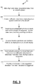
- FIG. 3 is a process flow chart depicting an example process 300 in flight deck equipment for providing task management assistance in managing the flight path to the flight crew.
- the order of operation within the process is not limited to the sequential execution as illustrated in the figure but may be performed in one or more varying orders as applicable and in accordance with the present disclosure.
- the process can be scheduled to run based on one or more predetermined events, and/or can run continuously during operation of the aircraft.
- the example process 300 includes mining flight plan data and navigational data from an aircraft system (operation 302).
- the mined flight plan data may include a plurality of waypoints and other course data items for a current flight plan.
- the mined navigational data may include aircraft location, speed, and heading data.
- the example process 300 includes obtaining notification data items originating from systems external to the aircraft (operation 304).
- the notification data items may indicate upcoming conditions that will affect the aircraft flight plan and a location at which the upcoming conditions will affect the aircraft flight plan.
- the example process 300 also includes determining an estimated flight time to reach each of the plurality of waypoints, course data items, and the upcoming conditions (operation 306).
- the example process 300 includes causing a timeline graphical user interface (GUI) to be displayed on an aircraft display (operation 308).
- the timeline GUI is configured to display a timeline, waypoint graphical elements representative of the waypoints, course data item graphical elements representative of the other course data items, and notification data item graphical elements representative of the upcoming conditions.
- course data item graphical element and notification data item graphical element is positioned on the timeline along with the estimated time for the aircraft to reach the graphical element.
- the example process 300 includes automatically analyzing the mined flight plan data and the notification data items to determine if deviation from the flight plan is suggested (operation 310) and providing a notification of the suggested deviation when deviation is suggested (operation 312).
- one or more flight path deviation recommendation options may be provided.
- the notification of the suggested deviation may be in the form of a selectable deviation notification graphical element displayed on the integrated interactive GUI.
- Selection of the selectable deviation notification graphical element may cause the display of one or more selectable deviation recommendation graphical elements, wherein each may contain graphical data that is descriptive of a flight path deviation recommendation option.
- Selection of a selectable deviation recommendation graphical element may cause a preview of a flight path deviation recommendation option to be displayed on the map GUI and/or the VSD GUI.
- a flight path deviation recommendation option selected by the flight crew may also be submitted to ATC for approval.
- a selectable activate graphical element for flight crew selection may also be provide. The selectable activate graphical element when selected may cause a selected flight path deviation recommendation option to be activated.
- FIG. 4 is a diagram depicting an example integrated interactive graphical user interface (GUI) 400 caused to be displayed by the integrated interactive display module 214.
- the example GUI 400 includes: (i) an example timeline GUI 402, generated by the timeline module 216, that presents a visual waypoint list on a timeline, (ii) an example map GUI 404, generated by the navigation display module 218, that may present a 'birds-eye' viewpoint of a portion of a flight plan (as illustrated) and/or a three-dimensional (3-D) viewpoint (not shown), and (iii) an example VSD GUI 406, generated by the VSD module 220.
- GUI integrated interactive graphical user interface
- the example timeline GUI 402 shows a visual waypoint list 410 on a timeline 408.
- the waypoint list 410 is organized on the timeline 408 by time.
- the timeline GUI 402 via the timeline, can provide a flight preview to allow flight crew to preview the entire route or some segment of it.
- the waypoint information on the example timeline GUI 402 may include: time, altitude, speed, course, distance, FPA (Flight Path Angle), constraints, wind direction/speed, and other flight related information.
- the timeline GUI 402 can show frequency changes (including automated frequency changes) at different points in the flight path.
- the timeline GUI 402 can provide access to normal checklists (e.g ., via checklist graphical element 414). Normal checklists are accessible via the waypoint list at the proper time and flight phase.
- the example timeline GUI 402 can provide Zulu to local time toggle at any point on the timeline.
- the example timeline GUI 402 can provide maximum altitude and fuel remaining at any point on the timeline.
- the example timeline GUI 402 can provide waypoint list scrolling and zooming and decluttering.
- the example timeline GUI 402 can provide flight crew defined reminders ( e.g ., at a specified distance, time, altitude).
- the example timeline GUI 402 can provide airport information at the destination ( e.g ., at the top of waypoint list).
- the example timeline GUI 402 can integrate a waypoint list with smart scratchpad interactions.
- the smart scratchpad displays information such as Air Traffic Control issued clearances or data-linked information on the timeline GUI.
- the example timeline GUI 402 can display the current wind speed/direction and distance to next waypoint.
- the example timeline GUI 402 can display aircraft configuration change points ( e.g., flaps, speed).
- the example timeline GUI 402 can provide access to a phase of flight briefing tool provided by the briefing tool processor 244 of the cognitive tools module 226.
- the phase of flight briefing tool provides briefing notes at the proper time and flight phase.
- the example timeline GUI 402 can provide position reporting points. During flight operations, the flight crew may be required to provide position reports to ATC and/or their Operator HQ. Position reporting points are defined geographic locations at which the pilot must report crossing and are used for tracking the flight. The timeline GUI 402 can provide a mechanism for the flight crew to send the report of their current position ( e.g ., lat/lon).
- the example timeline GUI 402 can facilitate tactical modifications of the flight plan (e.g., direct to modification) via the flight path deviation processor 228 of the cognitive tools module 226.
- the example timeline GUI 402 can display aeronautical information retrieved from automatic terminal information service (ATIS) broadcasts ( e.g ., by the data mining module 212).
- the flight crew may search the example timeline GUI 402 for flight related aeronautical information.
- UATS automatic terminal information service
- the example timeline GUI 402 can allow for departure/arrival selection. Departure and arrival procedures govern the flight path the aircraft will fly when it departs or arrives at an airport. These airspace procedures must be selected and input into the flight management system. Before flight, the example timeline GUI 402 can allow the flight crew to directly update the airport city pair (departure and arrival airports) in the flight plan. For flights that are en route, the example timeline GUI 402 can allow the flight crew to directly update the arrival airport, which would cause the generation of a new flight plan and associated waypoints, fuel burn, ETA, etc.
- the example timeline GUI 402 can allow for normal checklist modification due to MEL (minimum equipment list) or NNC (non-normal checklist).
- the timeline GUI 402 can allow for updates and modifications to checklists if there is an equipment failure (e.g ., indicated by the MEL) or some sort of weather condition that requires a different checklist to be displayed due to the effects of the condition on the aircraft or the flight plan. If a MEL or NNC requires a change to a normal checklist step, the change would be indicated in the normal checklist on the timeline.
- the example timeline GUI 402 can indicate the active mode and next mode change. Active modes are those that are currently engaged by the autopilot. Next modes are those that are armed to become active subsequently once the relevant conditions are met.
- the example timeline GUI 402 can display various notifications.
- the notifications may include significant weather along planned flight plan (e.g., icon 412), airport information changes at the destination airport, ATIS updates, NOTAMs filtered for computed flight plan, incomplete checklists/tasks, special use airspace notifications, temporary flight restrictions (TFRs), departure/arrival delays, and others.
- the example timeline GUI 402 can allow for multi-modal interaction (touch, speech, gesture, cursor).
- the example map GUI 404 can toggle between birds-eye and exocentric perspective view.
- the example map GUI 404 can show volumetric representation of weather, precipitation, clouds on navigation layer relative to flight path, and exocentric view of aircraft (as illustrated in FIG. 5 ).
- the example map GUI 404 can show a best alternate along the route of flight with predefined criteria and pilot selectable criteria.
- the example VSD GUI 406 can provide performance limitations/capabilities (e.g., inflight restart envelope, drift-down, etc.).
- the example VSD GUI 406 can show a vertical direct to route change.
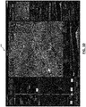
- FIG. 5 is a diagram depicting another example integrated interactive graphical user interface (GUI) 500 caused to be displayed by the integrated interactive display module 214.
- the example GUI 500 includes: (i) an example timeline GUI 502, generated by the timeline module 216, that presents a visual waypoint list on a timeline, (ii) an example map GUI 504, generated by the navigation display module 218, that, in this example, presents a 3-D viewpoint, and (iii) an example VSD GUI 506, generated by the VSD module 220.
- the integrated interactive GUI 500 includes on the map GUI 504 a graphical depiction of a weather pattern 508 threatening the flight path 510 and a weather alert graphical element 512, overlaid over the map GUI 504.
- the weather alert graphical element 512 includes a selectable button 514 to allow a user to view automatically generated flight path deviation recommendations calculated by the system ( e.g ., flight path deviation processor128) due to the threatening weather pattern 508.
- the weather alert graphical element 512 is displayed as a result of user selection of the significant weather icon 516 displayed on the timeline GUI 502.
- FIG. 6 is a diagram depicting another example integrated interactive graphical user interface (GUI) 600 caused to be displayed by the integrated interactive display module 214.
- the example GUI 600 includes: (i) an example timeline GUI 602, generated by the timeline module 216, that presents a visual waypoint list on a timeline, (ii) an example map GUI 604, generated by the navigation display module 218, that, in this example, presents birds-eye viewpoint, and (iii) an example VSD GUI 606, generated by the VSD module 220.
- the integrated interactive GUI 600 includes on the map GUI 604 a graphical depiction of a weather pattern 608 threatening the flight path 610 and a weather alert graphical element 612, overlaid over the map GUI 604.
- the weather alert graphical element 612 includes a selectable button 614 to allow a user to view automatically generated flight path deviation recommendations calculated by the system ( e.g ., flight path deviation processor128) due to the threatening weather pattern 608.
- the weather alert graphical element 612 is displayed as a result of user selection of the significant weather icon 616 displayed on the timeline GUI 602.
- FIG. 7 is a diagram depicting another example integrated interactive graphical user interface (GUI) 700 caused to be displayed by the integrated interactive display module 214.
- the example GUI 700 includes: (i) an example timeline GUI 702, generated by the timeline module 216, that presents a visual waypoint list on a timeline, (ii) an example map GUI 704, generated by the navigation display module 218, that, in this example, presents a 3-D viewpoint, (iii) an example VSD GUI 706, generated by the VSD module 220, (iv) a first deviation recommendation GUI 708, and (v) a second deviation recommendation GUI 710.
- the first deviation recommendation GUI 708 shows a lateral flight path deviation recommendation 712 and the second deviation recommendation GUI 708 shows a vertical flight path deviation recommendation 714.
- the deviation recommendation GUIs 708, 710 also show flight differences achieved by taking the recommendation.
- the first deviation recommendation GUI 708 shows that fuel remaining from accepting the deviation recommendation increases from 2h 4m to 2h 14m and shows that estimated travel decreases from 2h 42m to 2h 30 m.
- the second deviation recommendation GUI 710 shows that fuel remaining from accepting the deviation recommendation decreases from 2h 4m to 1h 45m and shows that estimated travel increases from 2h 42m to 3h 1 m.
- Each of the first deviation recommendation GUI 708 and the second deviation recommendation GUI 708 includes a selectable preview button 716, 718.
- Selection of the preview button 716 can cause the first recommendation to be previewed on the map GUI 704 as flight path deviation 720.
- Selection of the preview button 718 can cause the second recommendation to be previewed on the map GUI 704 as flight path deviation 722 and on the VSD GUI 706 as flight path deviation 724.
- FIG. 8 is a diagram depicting another example integrated interactive graphical user interface (GUI) 800 caused to be displayed by the integrated interactive display module 214.
- the example GUI 800 includes: (i) an example timeline GUI 802, generated by the timeline module 216, that presents a visual waypoint list on a timeline, (ii) an example map GUI 804, generated by the navigation display module 218, that, in this example, presents a birds-eye viewpoint, (iii) an example VSD GUI 806, generated by the VSD module 220, (vi) a first deviation recommendation GUI 808, and (v) a second deviation recommendation GUI 810.
- the first deviation recommendation GUI 808 shows a lateral flight path deviation recommendation 812 and the second deviation recommendation GUI 808 shows a vertical flight path deviation recommendation 814.
- the deviation recommendation GUIs 808, 810 also show flight differences achieved by taking the recommendation.
- the first deviation recommendation GUI 808 shows that fuel remaining from accepting the deviation recommendation increases from 2h 4m to 2h 14m and shows that estimated travel decreases from 2h 42m to 2h 30 m.
- the second deviation recommendation GUI 810 shows that fuel remaining from accepting the deviation recommendation decreases from 2h 4m to 1h 45m and shows that estimated travel increases from 2h 42m to 3h 1 m.
- Each of the first deviation recommendation GUI 808 and the second deviation recommendation GUI 808 includes a selectable preview button 816, 818. Selection of the preview button 816 can cause the first recommendation to be previewed on the map GUI 804 as flight path deviation 820. Selection of the preview button 818 can cause the second recommendation to be previewed on the VSD GUI 806 as flight path deviation 824.
- FIG. 9 is a diagram depicting another example integrated interactive graphical user interface (GUI) 900 caused to be displayed by the integrated interactive display module 214.
- the example GUI 900 includes: (i) an example timeline GUI 902, generated by the timeline module 216, that presents a visual waypoint list on a timeline, (ii) an example map GUI 904, generated by the navigation display module 218, that, in this example, presents a birds-eye viewpoint, (iii) an example VSD GUI 906, generated by the VSD module 220, (vi) a first deviation recommendation GUI 908, and (v) a second deviation recommendation GUI 910.
- the first deviation recommendation GUI 908 and the second deviation recommendation GUI 908 are overlaid the map GUI 904.
- the deviation recommendation GUIs 908, 910 also show flight differences achieved by taking the recommendation.
- the first deviation recommendation GUI 908 shows lower fuel burn of -10m, faster travel of -12m, and moderate turbulence from accepting the deviation recommendation.
- the second deviation recommendation GUI 910 shows higher fuel burn of -15m, longer travel of -20m, and light turbulence from accepting the deviation recommendation.
- Each of the first deviation recommendation GUI 908 and the second deviation recommendation GUI 908 includes a selectable preview button 912, 914. Selection of the preview button 912 can cause the first recommendation to be previewed on the map GUI 904 as flight path deviation 916. Selection of the preview button 914 can cause the second recommendation to be previewed on the VSD GUI 906 as flight path deviation 918.
- FIG. 10 is a diagram depicting another example integrated interactive graphical user interface (GUI) 1000 caused to be displayed by the integrated interactive display module 214.
- the example GUI 1000 includes: (i) an example timeline GUI 1002, generated by the timeline module 216, that presents a visual waypoint list on a timeline, (ii) an example map GUI 1004, generated by the navigation display module 218, that, in this example, presents a birds-eye viewpoint, (iii) an example VSD GUI 1006, generated by the VSD module 220, (iv) a first deviation recommendation GUI 1008, (v) a second deviation recommendation 1010 GUI, and (vi) an activation GUI 1012 that includes an activate button 1014 and a cancel button 1016.
- GUI integrated interactive graphical user interface
- selection of the Direct-to deviation option results in the Direct-to activation GUI 1012 being displayed.
- Selection of the activate button 1014 causes the activation of the selected deviation option and a change in the timeline display 1018 that reflects the change in flight path due to the selected flight path deviation.
- FIG. 11 is a diagram depicting another example integrated interactive graphical user interface (GUI) 1100 caused to be displayed by the integrated interactive display module 214.
- the example GUI 1100 includes: (i) an example timeline GUI 1102, generated by the timeline module 216, that presents a visual waypoint list on a timeline, (ii) an example map GUI 1104, generated by the navigation display module 218, that, in this example, presents a birds-eye viewpoint, (iii) an example VSD GUI 1106, generated by the VSD module 220, (vi) a first deviation recommendation GUI 1108, and (v) a second deviation recommendation GUI 1110.
- the first deviation recommendation GUI 1108 and the second deviation recommendation GUI 1108 are overlaid the map GUI 1104.
- Selection of the Direct-to deviation option results in the Direct-to activation GUI 1112 being displayed.
- Selection of the activate button 1114 causes the activation of the selected deviation option and a change in the timeline display 1118 that reflects the change in flight path due to the selected flight path deviation.
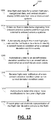
- FIG. 12 is a process flow chart depicting an example process 1200 in flight deck equipment for providing task management assistance in managing the flight path to the flight crew.
- the order of operation within the process is not limited to the sequential execution as illustrated in the figure but may be performed in one or more varying orders as applicable and in accordance with the present disclosure.
- the process can be scheduled to run based on one or more predetermined events, and/or can run continuously during operation of the aircraft.
- the example process 1200 includes mining flight plan data for a current flight plan, navigational data, and vertical situation display (VSD) data from one or more aircraft systems (operation 1202).
- the mined flight plan data may include a plurality of waypoints and other course data items for a current flight plan.
- the other course data items may include a plurality of a scheduled altitude change, scheduled speed change, a scheduled heading change, and an altitude, speed, or time restriction.
- the mined navigational data may include aircraft location, speed, and heading data.
- the mined VSD data may include a vertical profile of the aircraft for the current flight plan, an altitude reference, terrain data, and glideslope data.
- the one or more aircraft systems may include an onboard flight management system (FMS); or an electronic flight bag (EFB) application on which the flight plan was created and wherein the flight plan was synced with or loaded into an onboard avionics system (such as, an onboard flight management system (FMS)) from the EFB application.
- FMS flight management system
- EFB electronic flight bag
- the example process 1200 includes obtaining notification data items originating from onboard avionics systems and from systems external to onboard avionics systems (operation 1204).
- the notification data items indicate upcoming conditions that will affect the current flight plan.
- the notification data items include airport data, runway data, navigation data, map data, weather data, ATC alert data, traffic alert data, applicable Notices to Airmen (NOTAMS), aviation electronic checklist data, aircraft data, aircraft weight data, aircraft fuel data, timing data, distance data, airport facilities data, emergency services data, aircraft equipment trouble alert, a flight crew configurable reminder, a hold reminder for a waypoint indicating a desire to hold at the waypoint, an airport change notice, special use airspace notice, departure delay notice, or arrival delay notice, legality data, and/or flight plan deviation data from one or more remote servers.
- NOTAMS Notices to Airmen
- the example process 1200 includes automatically analyzing the mined flight plan data and the notification data items to identify a sensed deviation condition when a sensed deviation condition exists (operation 1206).
- a sensed deviation condition may include a weather condition along or approaching the flight path, an airport closure at a planned destination airport, a runway closure at a planned destination runway, and/or an airspace restriction along the planned flight path that causes a desire for a flight plan deviation.
- the example process 1200 includes automatically identifying an aircraft-related deviation condition from an aircraft failure event when an aircraft failure event exists (operation 1208).
- An aircraft failure event may include a hydraulic failure, electrical system failure, engine failure, and/or flight automation failure
- the example process 1200 includes receiving flight crew notification of a non-sensed deviation condition when a non-sensed deviation condition exists (operation 1210).
- a non-sensed deviation condition comprises an on-board medical emergency.
- the example process 1200 includes automatically determining one or more modifications to the current flight plan (operation 1212).
- the one or more modifications are determined to generate a plurality of flight plan deviation options to accommodate a sensed deviation condition, an aircraft-related deviation condition, or a non-sensed deviation condition.
- Automatically determining one or more modifications to the current flight plan to generate a plurality of flight plan deviation options may include incorporating operational limitations and checklist requirements in deviation planning.
- the example process 1200 includes presenting graphical elements representative of the flight plan deviation options to the flight crew (operation 1214).
- the deviation options are presented on an integrated interactive graphical user interface (GUI) comprising a timeline GUI, a map GUI, and a VSD GUI displayed on an aircraft display.
- Presenting graphical elements representative of the flight plan deviation options to the flight crew on an integrated interactive graphical user interface (GUI) may include causing the display of a selectable deviation notification graphical element on the integrated interactive GUI.
- Selection of a selectable deviation notification graphical element may cause the display of one or more selectable deviation recommendation graphical elements, each containing graphical data that is descriptive of a flight path deviation recommendation option.
- Selection of a selectable deviation recommendation graphical element may cause a preview of a flight path deviation recommendation option to be displayed on the map GUI and/or the VSD GUI.
- the timeline GUI may be configured to display a timeline, waypoint graphical elements representative of the waypoints, course data item graphical elements representative of the other course data items, and notification data item graphical elements representative of upcoming conditions, and wherein when displayed each waypoint graphical element, course data item graphical element and notification data item graphical element is positioned on the timeline along with the estimated time for the aircraft to reach the graphical element.
- Presenting graphical elements representative of the flight plan deviation options to the flight crew may further allow for submitting a flight path deviation recommendation option selected by the flight crew to ATC for approval and providing a selectable activate graphical element for flight crew selection that when selected causes a selected flight path deviation recommendation option to be activated.
- a flight deck system for providing task management assistance in managing the flight path to the flight crew.
- the system comprises one or more processors configured by programming instructions on non-transient computer readable media.
- the system is configured to: mine flight plan data, navigational data, and vertical situation display (VSD) data from one or more aircraft systems, the mined flight plan data including a plurality of waypoints and other course data items for a current flight plan, the mined navigational data comprising aircraft location, speed, and heading data, the mined VSD data comprising a vertical profile of the aircraft for the current flight plan, an altitude reference, terrain data, and glideslope data; obtain notification data items originating from systems external to avionics systems on the aircraft that indicate upcoming conditions that will affect the aircraft flight plan and a location at which the upcoming conditions will affect the aircraft flight plan; determine an estimated flight time to reach each of the plurality of waypoints, course data items, and the upcoming conditions; cause an integrated interactive graphical user interface (GUI) comprising a timeline GUI, a map GUI
- the flight deck system may be configured to analyze the mined flight plan data and the notification data items to identify a mission altering event (e.g., non-emergency condition) that due to time, fuel or safety considerations raises concerns regarding the current aircraft travel path and identify one or more flight path deviation recommendation options for the aircraft to minimize the impact of or avoid the mission altering event.
- the notification of the suggested deviation may be in the form of a selectable deviation notification graphical element displayed on the integrated interactive GUI. Selection of the selectable deviation notification graphical element may cause the display of one or more selectable deviation recommendation graphical elements, each containing graphical data that may be descriptive of a flight path deviation recommendation option.
- Selection of a selectable deviation recommendation graphical element may cause a preview of a flight path deviation recommendation option to be displayed on the map GUI and/or the VSD GUI.
- the flight deck system may be further configured to submit a flight path deviation recommendation option selected by the flight crew to ATC for approval.
- the flight deck system may be further configured to provide a selectable activate graphical element for flight crew selection that when selected causes a selected flight path deviation recommendation option to be activated.
- the map GUI may be configurable to switch between displaying a three-dimensional (3-D) map display and a birds-eye view map display.
- the other course data items may comprise a plurality of a scheduled altitude change, scheduled speed change, a scheduled heading change, and an altitude, speed, or time restriction.
- the flight deck system may be configured to determine an estimated flight time based on the navigational data (e.g. current aircraft location, speed, heading).
- the notification data items may comprise one or more of an aviation electronic checklist, a weather alert, an ATC alert, a traffic alert, NOTAMS, aircraft equipment trouble alert, a flight crew configurable reminder, a hold reminder for a waypoint indicating a desire to hold at the waypoint, an airport change notice (e.g., closed runway, destination airport problem), special use airspace notice, departure delay notice, or arrival delay notice.
- the notification data items may be selectable and when selected causes the display of additional information regarding the notification data item.
- the timeline may be a moving timeline that may be systematically adjusted to show displayed waypoint graphical elements, course data item graphical elements, and notification data item graphical elements moving closer to an aircraft graphical element representative of the aircraft located at one end of the moving timeline.
- the timeline GUI may be configured to display, adjacent to each displayed waypoint graphical element, course data item graphical element, and notification data item graphical element the projected time to reach and a distance from the location at which the waypoint graphical element, course data item graphical element, and notification data item graphical element may be relevant.
- the flight deck system may further comprise a flight path deviation processor, wherein the flight path deviation processor comprises one or more processors configured by programming instructions on non-transient computer readable media.
- the flight path deviation processor may be a rule-based system that compares options for lateral and vertical flight path deviations and presents the computed best options based on current aircraft performance. Deviation recommendations from the flight path deviation processor may be accessible directly from a link on the timeline GUI.
- the flight deck system may further comprise an airport diversion processor, wherein the airport diversion processor comprises one or more processors configured by programming instructions on non-transient computer readable media.
- the airport diversion processor may be a rule-based system that compares options for diversions and presents the best airport options based on current aircraft performance, fuel, airport services, and runways, distance, or other pilot selectable criteria, and wherein the airport diversion assistant may be accessible directly from a link on the timeline GUI and from non-normal checklists that require landing as soon as practical.
- the flight deck system may further comprise an Arrival/departure windows processor configured to calculate Arrival/departure windows at an airport due to limitations and weather, wherein the Arrival/departure windows processor comprises one or more processors configured by programming instructions on non-transient computer readable media.
- the Arrival/departure windows processor may be a rule based system that shows the current arrival/departure timing at the departure airport and destination airport given the current aircraft performance and weather.
- the flight deck system may further comprise a route calculation processor for computing the best alternate route based on a set of default criteria as well as pilot selectable criteria.
- the route calculation processor comprises one or more processor configured by programming instructions on non-transient computer readable media.
- the route calculation processor may be a rule-based system that searches the airport database and airport information to match the criteria and presents options to the flight crew.
- the flight deck system may further comprise a routing patterns processor for computing ATC/routing patterns along planned route/destination.
- the routing patterns processor comprises one or more processors configured by programming instructions on non-transient computer readable media.
- the routing patterns processor may be a machine learning system that merges historical air traffic data with weather data and current traffic and ATC routing to show what the current air traffic and how that may change when a significant event, such as weather or airport closure, occurs.
- the flight deck system may further comprise a weather tracking processor for weather tracking along the route.
- the weather tracking processor comprises one or more processors configured by programming instructions on non-transient computer readable media.
- the weather tracking processor may be configured to continuously monitor weather data to provide a notice to the flight crew when the ceiling at the destination approaches minimums or may be below minimums.
- the flight deck system may further comprise a Missed approach/Go around processor.
- the Missed approach/Go around processor comprises one or more processors configured by programming instructions on non-transient computer readable media.
- the Missed approach/Go around processor may be configured to
- the flight deck system may further comprise a conversion calculation processor for converting different units, such as pounds to kilograms, feet to meters, kilometers to nautical miles, statute miles to nautical miles, and more.
- the conversion calculation processor comprises one or more processors configured by programming instructions on non-transient computer readable media.
- the conversion calculation processor may be made available for use via the timeline GUI.
- the flight deck system may further comprise a briefing tool processor for guiding pilot through briefing items for the next flight phase.
- the briefing tool processor may comprise one or more processors configured by programming instructions on non-transient computer readable media.
- the briefing tool processor is configured to display the briefing verbiage, procedure to be flown, and associated charts.
- a method in a flight deck system for providing task management assistance in managing the flight path to the flight crew comprises: mining flight plan data and navigational data from an aircraft system, wherein the mined flight plan data includes a plurality of waypoints and other course data items for a current flight plan, and wherein the mined navigational data comprises aircraft location, speed, and heading data; obtaining notification data items originating from systems external to the aircraft that indicate upcoming conditions that will affect the aircraft flight plan and a location at which the upcoming conditions will affect the aircraft flight plan; determining an estimated flight time to reach each of the plurality of waypoints, course data items, and the upcoming conditions; causing a timeline graphical user interface (GUI) to be displayed on an aircraft display, wherein the timeline GUI is configured to display a timeline, waypoint graphical elements representative of the waypoints, course data item graphical elements representative of the other course data items, and notification data item graphical elements representative of the upcoming conditions, and wherein when displayed each waypoint graphical element, course data item
- the method may further comprise generating one or more flight path deviation recommendation options when deviation is suggested.
- the notification of the suggested deviation may be in the form of a selectable deviation notification graphical element displayed on the integrated interactive GUI.
- Selection of the selectable deviation notification graphical element may cause the display of one or more selectable deviation recommendation graphical elements, wherein each contains graphical data that is descriptive of a flight path deviation recommendation option.
- Selection of a selectable deviation recommendation graphical element may cause a preview of a flight path deviation recommendation option to be displayed on the map GUI and/or the VSD GUI.
- the method may further comprise submitting a flight path deviation recommendation option selected by the flight crew to ATC for approval.
- the method may further comprise providing a selectable activate graphical element for flight crew selection that when selected causes a selected flight path deviation recommendation option to be activated.
- non-transient computer readable media encoded with programming instructions configurable to cause a processor in an aircraft to perform a method comprises: mining flight plan data and navigational data from an aircraft system, wherein the mined flight plan data includes a plurality of waypoints and other course data items for a current flight plan, and wherein the mined navigational data comprises aircraft location, speed, and heading data; obtaining notification data items originating from systems external to the aircraft that indicate upcoming conditions that will affect the aircraft flight plan and a location at which the upcoming conditions will affect the aircraft flight plan; determining an estimated flight time to reach each of the plurality of waypoints, course data items, and the upcoming conditions; causing a timeline graphical user interface (GUI) to be displayed on an aircraft display, wherein the timeline GUI is configured to display a timeline, waypoint graphical elements representative of the waypoints, course data item graphical elements representative of the other course data items, and notification data item graphical elements representative of the upcoming conditions, and wherein when displayed each waypoint graphical element
- GUI timeline graphical user interface
- a flight deck system for providing task management assistance in managing the flight path to the flight crew.
- the system comprises one or more processors configured by programming instructions on non-transient computer readable media.
- the system is configured to: mine flight plan data for a current flight plan, navigational data, and vertical situation display (VSD) data from one or more aircraft systems; obtain notification data items originating from onboard avionics systems and from systems external to onboard avionics systems that indicate upcoming conditions that will affect the current flight plan; automatically analyze the mined flight plan data and the notification data items to identify a sensed deviation condition; automatically identify an aircraft-related deviation condition from an aircraft failure event; receive flight crew notification of a non-sensed deviation condition; automatically determine one or more modifications to the current flight plan to generate a plurality of flight plan deviation options to accommodate a sensed deviation condition, an aircraft-related deviation condition, or a non-sensed deviation condition; and present graphical elements representative of the flight plan deviation options to the flight crew on an integrated interactive graphical user interface (GUI) comprising
- a deviation condition may comprise a weather condition along or approaching the flight path, an airport closure at a planned destination airport, a runway closure at a planned destination runway, and/or an airspace restriction along the planned flight path that causes a desire for a flight plan deviation.
- the aircraft failure event may comprise a hydraulic failure, electrical system failure, engine failure, and/or flight automation failure.
- the non-sensed deviation condition may comprise an on-board medical emergency.
- the flight deck system may be configured to incorporate operational limitations and checklist requirements in deviation planning.
- the flight deck system may be configured to cause the display of a selectable deviation notification graphical element on the integrated interactive GUI.
- Selection of a selectable deviation notification graphical element may cause the display of one or more selectable deviation recommendation graphical elements, wherein each contains graphical data that may be descriptive of a flight path deviation recommendation option.
- Selection of a selectable deviation recommendation graphical element may cause a preview of a flight path deviation recommendation option to be displayed on the map GUI and/or the VSD GUI.
- the flight deck system may be further configured to submit a flight path deviation recommendation option selected by the flight crew to ATC for approval.
- the flight deck system may be further configured to provide a selectable activate graphical element for flight crew selection that when selected causes a selected flight path deviation recommendation option to be activated.
- the flight deck system may further comprise a flight path deviation processor, wherein the flight path deviation processor comprises one or more processor configured by programming instructions on non-transient computer readable media.
- the flight path deviation processor may be a rule-based system that compares options for lateral and vertical flight path deviations and presents the computed best options based on current aircraft performance.
- the flight path deviation processor may be accessible directly from a link on the timeline GUI.
- the one or more aircraft systems may comprise: an onboard flight management system (FMS), or an electronic flight bag (EFB) application on which the flight plan was created and wherein the flight plan was synced with or loaded into an onboard avionics system (such as, an onboard flight management system (FMS)) from the EFB application.
- the mined flight plan data may include a plurality of waypoints and other course data items for a current flight plan, wherein the other course data items comprises a plurality of a scheduled altitude change, scheduled speed change, a scheduled heading change, and an altitude, speed, or time restriction.
- the mined navigational data may include aircraft location, speed, and heading data.
- the mined VSD data may include a vertical profile of the aircraft for the current flight plan, an altitude reference, terrain data, and glideslope data.
- the notification data items may comprise airport data, runway data, navigation data, map data, weather data, ATC alert data, traffic alert data, applicable Notices to Airmen (NOTAMS), aviation electronic checklist data, aircraft data, aircraft weight data, aircraft fuel data, timing data, distance data, airport facilities data, emergency services data, aircraft equipment trouble alert, a flight crew configurable reminder, a hold reminder for a waypoint indicating a desire to hold at the waypoint, an airport change notice, special use airspace notice, departure delay notice, or arrival delay notice, legality data, and/or flight plan deviation data from one or more remote servers.
- NOTAMS Notices to Airmen
- the timeline GUI may be configured to display a timeline, waypoint graphical elements representative of the waypoints, course data item graphical elements representative of the other course data items, and notification data item graphical elements representative of upcoming conditions, and wherein when displayed each waypoint graphical element, course data item graphical element and notification data item graphical element may be positioned on the timeline along with the estimated time for the aircraft to reach the graphical element.
- a method in a flight deck system for providing task management assistance in managing the flight path to the flight crew comprises: mining flight plan data for a current flight plan, navigational data, and vertical situation display (VSD) data from one or more aircraft systems; obtaining notification data items originating from onboard avionics systems and from systems external to onboard avionics systems that indicate upcoming conditions that will affect the current flight plan; automatically analyzing the mined flight plan data and the notification data items to identify a sensed deviation condition when a sensed deviation condition exists; automatically identifying an aircraft-related deviation condition from an aircraft failure event when an aircraft failure event exists; receiving flight crew notification of a non-sensed deviation condition when a non-sensed deviation condition exists; automatically determining one or more modifications to the current flight plan to generate a plurality of flight plan deviation options to accommodate a sensed deviation condition, an aircraft-related deviation condition, or a non-sensed deviation condition; and presenting graphical elements representative of the flight plan deviation options to the flight crew on an integrated interactive
- Presenting graphical elements representative of the flight plan deviation options to the flight crew on an integrated interactive graphical user interface may comprise causing the display of a selectable deviation notification graphical element on the integrated interactive GUI.
- the method may further comprise receiving the selection of a selectable deviation notification graphical element, wherein the selection of a selectable deviation notification graphical element causes the display of one or more selectable deviation recommendation graphical elements, each containing graphical data that is descriptive of a flight path deviation recommendation option.
- the method may further comprise receiving the selection of a selectable deviation recommendation graphical element, wherein receiving the selection of a selectable deviation recommendation graphical element causes a preview of a flight path deviation recommendation option to be displayed on the map GUI and/or the VSD GUI.
- the method may further comprise submitting a flight path deviation recommendation option selected by the flight crew to ATC for approval.
- the method may further comprise providing a selectable activate graphical element for flight crew selection that when selected causes a selected flight path deviation recommendation option to be activated.
- non-transient computer readable media encoded with programming instructions is provided.
- the programming instructions are configurable to cause a processor on an aircraft to: mine flight plan data for a current flight plan, navigational data, and vertical situation display (VSD) data from one or more aircraft systems; obtain notification data items originating from onboard avionics systems and from systems external to onboard avionics systems that indicate upcoming conditions that will affect the current flight plan; automatically analyze the mined flight plan data and the notification data items to identify a sensed deviation condition; automatically identify an aircraft-related deviation condition from an aircraft failure event; receive flight crew notification of a non-sensed deviation condition; automatically determine one or more modifications to the current flight plan to generate a plurality of flight plan deviation options to accommodate a sensed deviation condition, an aircraft-related deviation condition, or a non-sensed deviation condition; and present graphical elements representative of the flight plan deviation options to the flight crew on an integrated interactive graphical user interface (GUI) comprising a timeline GUI, a map GUI, and a VSD GUI displayed on an
- Skilled artisans may implement the described functionality in varying ways for each particular application, but such implementation decisions should not be interpreted as causing a departure from the scope of the present invention.
- an embodiment of a system or a component may employ various integrated circuit components, e.g., memory elements, digital signal processing elements, logic elements, look-up tables, or the like, which may carry out a variety of functions under the control of one or more microprocessors or other control devices.
- integrated circuit components e.g., memory elements, digital signal processing elements, logic elements, look-up tables, or the like, which may carry out a variety of functions under the control of one or more microprocessors or other control devices.
- DSP digital signal processor
- ASIC application specific integrated circuit
- FPGA field programmable gate array
- a general-purpose processor may be a microprocessor, but in the alternative, the processor may be any conventional processor, controller, microcontroller, or state machine.
- a processor may also be implemented as a combination of computing devices, e.g., a combination of a DSP and a microprocessor, a plurality of microprocessors, one or more microprocessors in conjunction with a DSP core, or any other such configuration.
- a software module may reside in RAM memory, flash memory, ROM memory, EPROM memory, EEPROM memory, registers, hard disk, a removable disk, a CD-ROM, or any other form of storage medium known in the art.
- An exemplary storage medium is coupled to the processor such that the processor can read information from, and write information to, the storage medium.
- the storage medium may be integral to the processor.
- the processor and the storage medium may reside in an ASIC.
- the ASIC may reside in a user terminal.
- the processor and the storage medium may reside as discrete components in a user terminal.
Landscapes
- Engineering & Computer Science (AREA)
- Aviation & Aerospace Engineering (AREA)
- Radar, Positioning & Navigation (AREA)
- Remote Sensing (AREA)
- Physics & Mathematics (AREA)
- General Physics & Mathematics (AREA)
- Life Sciences & Earth Sciences (AREA)
- Atmospheric Sciences (AREA)
- Traffic Control Systems (AREA)
Applications Claiming Priority (3)
| Application Number | Priority Date | Filing Date | Title |
|---|---|---|---|
| US201862772040P | 2018-11-27 | 2018-11-27 | |
| US16/598,026 US11532235B2 (en) | 2018-11-27 | 2019-10-10 | Systems and methods for providing deviation assistance on an integrated flight management display |
| US16/598,019 US11417220B2 (en) | 2018-11-27 | 2019-10-10 | Systems and methods for providing an integrated flight management display with interactive time-based functionality |
Publications (2)
| Publication Number | Publication Date |
|---|---|
| EP3660461A1 true EP3660461A1 (de) | 2020-06-03 |
| EP3660461B1 EP3660461B1 (de) | 2022-04-06 |
Family
ID=68696255
Family Applications (1)
| Application Number | Title | Priority Date | Filing Date |
|---|---|---|---|
| EP19211365.2A Active EP3660461B1 (de) | 2018-11-27 | 2019-11-25 | Systeme und verfahren zur unterstützung von abweichungen auf einer integrierten flugmanagementanzeige |
Country Status (1)
| Country | Link |
|---|---|
| EP (1) | EP3660461B1 (de) |
Cited By (9)
| Publication number | Priority date | Publication date | Assignee | Title |
|---|---|---|---|---|
| CN113589834A (zh) * | 2021-08-11 | 2021-11-02 | 深圳微希科技有限公司 | 一种多层级组件化的无人机飞行控制系统 |
| EP3939892A1 (de) * | 2020-07-13 | 2022-01-19 | Honeywell International Inc. | Systeme und verfahren zur anzeige von wetterdaten |
| EP3940673A1 (de) * | 2020-07-14 | 2022-01-19 | Honeywell International Inc. | Systeme und verfahren zur darstellung von umgebungsinformationen über eine missionszeitachse |
| US11472567B2 (en) | 2020-07-14 | 2022-10-18 | Honeywell International Inc. | Systems and methods for presenting environment information on a mission timeline |
| EP4105913A1 (de) * | 2021-06-11 | 2022-12-21 | Rockwell Collins, Inc. | Fahrzeugsystem und verfahren zur vorscharfschaltung von aktionen gemäss einer bedingten zeitlinie und zugehörigen auslöseereignissen |
| EP4113481A1 (de) * | 2021-06-30 | 2023-01-04 | Honeywell International Inc. | Systeme und verfahren zum präsentieren von nachrichten für die flugbesatzung |
| EP4170628A1 (de) * | 2021-10-22 | 2023-04-26 | Honeywell International Inc. | Pilotflugbahnrückkopplungswerkzeug |
| EP4210022A1 (de) * | 2022-01-05 | 2023-07-12 | Honeywell International Inc. | Systeme und verfahren zur korrigierung einer extern empfohlenen flugplanänderung mit einem flugmanagementsystem |
| US12026603B2 (en) | 2021-08-02 | 2024-07-02 | Rockwell Collins, Inc. | Visualization of predictive health monitoring |
Citations (5)
| Publication number | Priority date | Publication date | Assignee | Title |
|---|---|---|---|---|
| US7765061B1 (en) * | 2006-05-18 | 2010-07-27 | Rockwell Collins, Inc. | Flight display system with enhanced temporal depiction of navigation information |
| US20130268878A1 (en) * | 2010-12-17 | 2013-10-10 | Yannick Le Roux | Method for the temporal display of the mission of an aircraft |
| US20150355832A1 (en) * | 2014-06-09 | 2015-12-10 | Honeywell International Inc. | System and method for providing enhanced hmi navigation |
| US20160041305A1 (en) * | 2014-08-11 | 2016-02-11 | The Boeing Company | 4d volumetric weather data processing and display |
| EP2985748A1 (de) * | 2014-08-13 | 2016-02-17 | Honeywell International Inc. | System und verfahren zur integrierten zeitbasierten benachrichtigung für verbessertes situationsbewusstsein |
-
2019
- 2019-11-25 EP EP19211365.2A patent/EP3660461B1/de active Active
Patent Citations (5)
| Publication number | Priority date | Publication date | Assignee | Title |
|---|---|---|---|---|
| US7765061B1 (en) * | 2006-05-18 | 2010-07-27 | Rockwell Collins, Inc. | Flight display system with enhanced temporal depiction of navigation information |
| US20130268878A1 (en) * | 2010-12-17 | 2013-10-10 | Yannick Le Roux | Method for the temporal display of the mission of an aircraft |
| US20150355832A1 (en) * | 2014-06-09 | 2015-12-10 | Honeywell International Inc. | System and method for providing enhanced hmi navigation |
| US20160041305A1 (en) * | 2014-08-11 | 2016-02-11 | The Boeing Company | 4d volumetric weather data processing and display |
| EP2985748A1 (de) * | 2014-08-13 | 2016-02-17 | Honeywell International Inc. | System und verfahren zur integrierten zeitbasierten benachrichtigung für verbessertes situationsbewusstsein |
Cited By (12)
| Publication number | Priority date | Publication date | Assignee | Title |
|---|---|---|---|---|
| EP3939892A1 (de) * | 2020-07-13 | 2022-01-19 | Honeywell International Inc. | Systeme und verfahren zur anzeige von wetterdaten |
| US11682311B2 (en) | 2020-07-13 | 2023-06-20 | Honeywell International Inc. | Systems and methods for displaying weather data |
| EP3940673A1 (de) * | 2020-07-14 | 2022-01-19 | Honeywell International Inc. | Systeme und verfahren zur darstellung von umgebungsinformationen über eine missionszeitachse |
| US11472567B2 (en) | 2020-07-14 | 2022-10-18 | Honeywell International Inc. | Systems and methods for presenting environment information on a mission timeline |
| EP4105913A1 (de) * | 2021-06-11 | 2022-12-21 | Rockwell Collins, Inc. | Fahrzeugsystem und verfahren zur vorscharfschaltung von aktionen gemäss einer bedingten zeitlinie und zugehörigen auslöseereignissen |
| US11953921B2 (en) | 2021-06-11 | 2024-04-09 | Rockwell Collins, Inc. | Vehicular system and method for pre-arming actions according to conditional timeline and associated trigger events |
| EP4113481A1 (de) * | 2021-06-30 | 2023-01-04 | Honeywell International Inc. | Systeme und verfahren zum präsentieren von nachrichten für die flugbesatzung |
| US12026603B2 (en) | 2021-08-02 | 2024-07-02 | Rockwell Collins, Inc. | Visualization of predictive health monitoring |
| CN113589834A (zh) * | 2021-08-11 | 2021-11-02 | 深圳微希科技有限公司 | 一种多层级组件化的无人机飞行控制系统 |
| CN113589834B (zh) * | 2021-08-11 | 2024-03-26 | 深圳微希科技有限公司 | 一种多层级组件化的无人机飞行控制系统 |
| EP4170628A1 (de) * | 2021-10-22 | 2023-04-26 | Honeywell International Inc. | Pilotflugbahnrückkopplungswerkzeug |
| EP4210022A1 (de) * | 2022-01-05 | 2023-07-12 | Honeywell International Inc. | Systeme und verfahren zur korrigierung einer extern empfohlenen flugplanänderung mit einem flugmanagementsystem |
Also Published As
| Publication number | Publication date |
|---|---|
| EP3660461B1 (de) | 2022-04-06 |
Similar Documents
| Publication | Publication Date | Title |
|---|---|---|
| US11532235B2 (en) | Systems and methods for providing deviation assistance on an integrated flight management display | |
| EP3660461B1 (de) | Systeme und verfahren zur unterstützung von abweichungen auf einer integrierten flugmanagementanzeige | |
| US9205916B2 (en) | Methods, systems, and apparatus for layered and multi-indexed flight management interface | |
| US20170183105A1 (en) | Display of meteorological data in aircraft | |
| US9335917B2 (en) | System and method for providing enhanced HMI navigation | |
| US20110118908A1 (en) | Methods and systems for management of airplane speed profile | |
| EP3048424B1 (de) | Verfahren und systeme für route-basierte anzeige meteorologischer informationsvorhersage | |
| US10089886B2 (en) | Vehicle decision support system | |
| US10854092B1 (en) | Method and system to improve the situational awareness of all aerodrome ground operations including all turnaround airport collaborative decision making (A-CDM) milestones in the cockpit | |
| CN110910677B (zh) | 在地面操作期间用于情境警报的系统和方法 | |
| US8781649B2 (en) | System and method for displaying in-trail procedure (ITP) opportunities on an aircraft cockpit display | |
| US9401091B2 (en) | System and method for displaying In-Trail Procedure (ITP) allocations on an aircraft cockpit display | |
| EP3657131B1 (de) | Verfahren und systeme zur darstellung von wegpunktlisten | |
| US20160049080A1 (en) | System and method for reducing in-trail procedure (itp) rejection ratio | |
| US20210233412A1 (en) | Systems and methods for reducing controller-pilot rejection ratios | |
| EP3628977B1 (de) | Systeme und verfahren zur verknüpfung kritischer flugreferenzdaten mit einem flugwegvektorsymbol | |
| US11655047B2 (en) | System and method for monitoring an electronic checklist and supporting sensors | |
| US20210253268A1 (en) | Systems and methods that optimize speed brake operations | |
| EP4432177A1 (de) | Vorhersage von dienstproblemen, die sich an flugzeugoperationen anpasst | |
| US20240308692A1 (en) | Service issue forecasting that adapts to aircraft operations | |
| EP3989141A1 (de) | System und verfahren zur überwachung einer elektronischen kontrollliste und zur unterstützung von sensoren | |
| EP4369326A1 (de) | Systeme und verfahren zur anzeige von rollinformationen in einem flugzeug | |
| EP4276794A1 (de) | Transkriptionssysteme und damit zusammenhängende ergänzungsverfahren | |
| EP3855410A1 (de) | Systeme und verfahren zur reduzierung des regler-pilot-zurückweisungsverhältnisses | |
| US20230368682A1 (en) | Transcription systems and related supplementation methods |
Legal Events
| Date | Code | Title | Description |
|---|---|---|---|
| PUAI | Public reference made under article 153(3) epc to a published international application that has entered the european phase |
Free format text: ORIGINAL CODE: 0009012 |
|
| STAA | Information on the status of an ep patent application or granted ep patent |
Free format text: STATUS: THE APPLICATION HAS BEEN PUBLISHED |
|
| AK | Designated contracting states |
Kind code of ref document: A1 Designated state(s): AL AT BE BG CH CY CZ DE DK EE ES FI FR GB GR HR HU IE IS IT LI LT LU LV MC MK MT NL NO PL PT RO RS SE SI SK SM TR |
|
| AX | Request for extension of the european patent |
Extension state: BA ME |
|
| STAA | Information on the status of an ep patent application or granted ep patent |
Free format text: STATUS: REQUEST FOR EXAMINATION WAS MADE |
|
| 17P | Request for examination filed |
Effective date: 20200617 |
|
| RBV | Designated contracting states (corrected) |
Designated state(s): AL AT BE BG CH CY CZ DE DK EE ES FI FR GB GR HR HU IE IS IT LI LT LU LV MC MK MT NL NO PL PT RO RS SE SI SK SM TR |
|
| GRAP | Despatch of communication of intention to grant a patent |
Free format text: ORIGINAL CODE: EPIDOSNIGR1 |
|
| STAA | Information on the status of an ep patent application or granted ep patent |
Free format text: STATUS: GRANT OF PATENT IS INTENDED |
|
| INTG | Intention to grant announced |
Effective date: 20210714 |
|
| GRAS | Grant fee paid |
Free format text: ORIGINAL CODE: EPIDOSNIGR3 |
|
| GRAA | (expected) grant |
Free format text: ORIGINAL CODE: 0009210 |
|
| STAA | Information on the status of an ep patent application or granted ep patent |
Free format text: STATUS: THE PATENT HAS BEEN GRANTED |
|
| AK | Designated contracting states |
Kind code of ref document: B1 Designated state(s): AL AT BE BG CH CY CZ DE DK EE ES FI FR GB GR HR HU IE IS IT LI LT LU LV MC MK MT NL NO PL PT RO RS SE SI SK SM TR |
|
| REG | Reference to a national code |
Ref country code: GB Ref legal event code: FG4D |
|
| REG | Reference to a national code |
Ref country code: CH Ref legal event code: EP |
|
| REG | Reference to a national code |
Ref country code: AT Ref legal event code: REF Ref document number: 1481741 Country of ref document: AT Kind code of ref document: T Effective date: 20220415 |
|
| REG | Reference to a national code |
Ref country code: IE Ref legal event code: FG4D |
|
| REG | Reference to a national code |
Ref country code: DE Ref legal event code: R096 Ref document number: 602019013368 Country of ref document: DE |
|
| REG | Reference to a national code |
Ref country code: LT Ref legal event code: MG9D |
|
| REG | Reference to a national code |
Ref country code: NL Ref legal event code: MP Effective date: 20220406 |
|
| REG | Reference to a national code |
Ref country code: AT Ref legal event code: MK05 Ref document number: 1481741 Country of ref document: AT Kind code of ref document: T Effective date: 20220406 |
|
| PG25 | Lapsed in a contracting state [announced via postgrant information from national office to epo] |
Ref country code: NL Free format text: LAPSE BECAUSE OF FAILURE TO SUBMIT A TRANSLATION OF THE DESCRIPTION OR TO PAY THE FEE WITHIN THE PRESCRIBED TIME-LIMIT Effective date: 20220406 |
|
| PG25 | Lapsed in a contracting state [announced via postgrant information from national office to epo] |
Ref country code: SE Free format text: LAPSE BECAUSE OF FAILURE TO SUBMIT A TRANSLATION OF THE DESCRIPTION OR TO PAY THE FEE WITHIN THE PRESCRIBED TIME-LIMIT Effective date: 20220406 Ref country code: PT Free format text: LAPSE BECAUSE OF FAILURE TO SUBMIT A TRANSLATION OF THE DESCRIPTION OR TO PAY THE FEE WITHIN THE PRESCRIBED TIME-LIMIT Effective date: 20220808 Ref country code: NO Free format text: LAPSE BECAUSE OF FAILURE TO SUBMIT A TRANSLATION OF THE DESCRIPTION OR TO PAY THE FEE WITHIN THE PRESCRIBED TIME-LIMIT Effective date: 20220706 Ref country code: LT Free format text: LAPSE BECAUSE OF FAILURE TO SUBMIT A TRANSLATION OF THE DESCRIPTION OR TO PAY THE FEE WITHIN THE PRESCRIBED TIME-LIMIT Effective date: 20220406 Ref country code: HR Free format text: LAPSE BECAUSE OF FAILURE TO SUBMIT A TRANSLATION OF THE DESCRIPTION OR TO PAY THE FEE WITHIN THE PRESCRIBED TIME-LIMIT Effective date: 20220406 Ref country code: GR Free format text: LAPSE BECAUSE OF FAILURE TO SUBMIT A TRANSLATION OF THE DESCRIPTION OR TO PAY THE FEE WITHIN THE PRESCRIBED TIME-LIMIT Effective date: 20220707 Ref country code: FI Free format text: LAPSE BECAUSE OF FAILURE TO SUBMIT A TRANSLATION OF THE DESCRIPTION OR TO PAY THE FEE WITHIN THE PRESCRIBED TIME-LIMIT Effective date: 20220406 Ref country code: ES Free format text: LAPSE BECAUSE OF FAILURE TO SUBMIT A TRANSLATION OF THE DESCRIPTION OR TO PAY THE FEE WITHIN THE PRESCRIBED TIME-LIMIT Effective date: 20220406 Ref country code: BG Free format text: LAPSE BECAUSE OF FAILURE TO SUBMIT A TRANSLATION OF THE DESCRIPTION OR TO PAY THE FEE WITHIN THE PRESCRIBED TIME-LIMIT Effective date: 20220706 Ref country code: AT Free format text: LAPSE BECAUSE OF FAILURE TO SUBMIT A TRANSLATION OF THE DESCRIPTION OR TO PAY THE FEE WITHIN THE PRESCRIBED TIME-LIMIT Effective date: 20220406 |
|
| PG25 | Lapsed in a contracting state [announced via postgrant information from national office to epo] |
Ref country code: RS Free format text: LAPSE BECAUSE OF FAILURE TO SUBMIT A TRANSLATION OF THE DESCRIPTION OR TO PAY THE FEE WITHIN THE PRESCRIBED TIME-LIMIT Effective date: 20220406 Ref country code: PL Free format text: LAPSE BECAUSE OF FAILURE TO SUBMIT A TRANSLATION OF THE DESCRIPTION OR TO PAY THE FEE WITHIN THE PRESCRIBED TIME-LIMIT Effective date: 20220406 Ref country code: LV Free format text: LAPSE BECAUSE OF FAILURE TO SUBMIT A TRANSLATION OF THE DESCRIPTION OR TO PAY THE FEE WITHIN THE PRESCRIBED TIME-LIMIT Effective date: 20220406 Ref country code: IS Free format text: LAPSE BECAUSE OF FAILURE TO SUBMIT A TRANSLATION OF THE DESCRIPTION OR TO PAY THE FEE WITHIN THE PRESCRIBED TIME-LIMIT Effective date: 20220806 |
|
| REG | Reference to a national code |
Ref country code: DE Ref legal event code: R097 Ref document number: 602019013368 Country of ref document: DE |
|
| PG25 | Lapsed in a contracting state [announced via postgrant information from national office to epo] |
Ref country code: SM Free format text: LAPSE BECAUSE OF FAILURE TO SUBMIT A TRANSLATION OF THE DESCRIPTION OR TO PAY THE FEE WITHIN THE PRESCRIBED TIME-LIMIT Effective date: 20220406 Ref country code: SK Free format text: LAPSE BECAUSE OF FAILURE TO SUBMIT A TRANSLATION OF THE DESCRIPTION OR TO PAY THE FEE WITHIN THE PRESCRIBED TIME-LIMIT Effective date: 20220406 Ref country code: RO Free format text: LAPSE BECAUSE OF FAILURE TO SUBMIT A TRANSLATION OF THE DESCRIPTION OR TO PAY THE FEE WITHIN THE PRESCRIBED TIME-LIMIT Effective date: 20220406 Ref country code: EE Free format text: LAPSE BECAUSE OF FAILURE TO SUBMIT A TRANSLATION OF THE DESCRIPTION OR TO PAY THE FEE WITHIN THE PRESCRIBED TIME-LIMIT Effective date: 20220406 Ref country code: DK Free format text: LAPSE BECAUSE OF FAILURE TO SUBMIT A TRANSLATION OF THE DESCRIPTION OR TO PAY THE FEE WITHIN THE PRESCRIBED TIME-LIMIT Effective date: 20220406 Ref country code: CZ Free format text: LAPSE BECAUSE OF FAILURE TO SUBMIT A TRANSLATION OF THE DESCRIPTION OR TO PAY THE FEE WITHIN THE PRESCRIBED TIME-LIMIT Effective date: 20220406 |
|
| PLBE | No opposition filed within time limit |
Free format text: ORIGINAL CODE: 0009261 |
|
| STAA | Information on the status of an ep patent application or granted ep patent |
Free format text: STATUS: NO OPPOSITION FILED WITHIN TIME LIMIT |
|
| 26N | No opposition filed |
Effective date: 20230110 |
|
| PG25 | Lapsed in a contracting state [announced via postgrant information from national office to epo] |
Ref country code: AL Free format text: LAPSE BECAUSE OF FAILURE TO SUBMIT A TRANSLATION OF THE DESCRIPTION OR TO PAY THE FEE WITHIN THE PRESCRIBED TIME-LIMIT Effective date: 20220406 |
|
| PG25 | Lapsed in a contracting state [announced via postgrant information from national office to epo] |
Ref country code: SI Free format text: LAPSE BECAUSE OF FAILURE TO SUBMIT A TRANSLATION OF THE DESCRIPTION OR TO PAY THE FEE WITHIN THE PRESCRIBED TIME-LIMIT Effective date: 20220406 |
|
| REG | Reference to a national code |
Ref country code: DE Ref legal event code: R119 Ref document number: 602019013368 Country of ref document: DE |
|
| PG25 | Lapsed in a contracting state [announced via postgrant information from national office to epo] |
Ref country code: MC Free format text: LAPSE BECAUSE OF FAILURE TO SUBMIT A TRANSLATION OF THE DESCRIPTION OR TO PAY THE FEE WITHIN THE PRESCRIBED TIME-LIMIT Effective date: 20220406 |
|
| REG | Reference to a national code |
Ref country code: CH Ref legal event code: PL |
|
| P01 | Opt-out of the competence of the unified patent court (upc) registered |
Effective date: 20230525 |
|
| REG | Reference to a national code |
Ref country code: BE Ref legal event code: MM Effective date: 20221130 |
|
| PG25 | Lapsed in a contracting state [announced via postgrant information from national office to epo] |
Ref country code: LI Free format text: LAPSE BECAUSE OF NON-PAYMENT OF DUE FEES Effective date: 20221130 Ref country code: CH Free format text: LAPSE BECAUSE OF NON-PAYMENT OF DUE FEES Effective date: 20221130 |
|
| PG25 | Lapsed in a contracting state [announced via postgrant information from national office to epo] |
Ref country code: LU Free format text: LAPSE BECAUSE OF NON-PAYMENT OF DUE FEES Effective date: 20221125 |
|
| PG25 | Lapsed in a contracting state [announced via postgrant information from national office to epo] |
Ref country code: IE Free format text: LAPSE BECAUSE OF NON-PAYMENT OF DUE FEES Effective date: 20221125 Ref country code: DE Free format text: LAPSE BECAUSE OF NON-PAYMENT OF DUE FEES Effective date: 20230601 |
|
| PG25 | Lapsed in a contracting state [announced via postgrant information from national office to epo] |
Ref country code: BE Free format text: LAPSE BECAUSE OF NON-PAYMENT OF DUE FEES Effective date: 20221130 |
|
| PG25 | Lapsed in a contracting state [announced via postgrant information from national office to epo] |
Ref country code: IT Free format text: LAPSE BECAUSE OF FAILURE TO SUBMIT A TRANSLATION OF THE DESCRIPTION OR TO PAY THE FEE WITHIN THE PRESCRIBED TIME-LIMIT Effective date: 20220406 |
|
| PGFP | Annual fee paid to national office [announced via postgrant information from national office to epo] |
Ref country code: FR Payment date: 20231123 Year of fee payment: 5 |
|
| PG25 | Lapsed in a contracting state [announced via postgrant information from national office to epo] |
Ref country code: HU Free format text: LAPSE BECAUSE OF FAILURE TO SUBMIT A TRANSLATION OF THE DESCRIPTION OR TO PAY THE FEE WITHIN THE PRESCRIBED TIME-LIMIT; INVALID AB INITIO Effective date: 20191125 |
|
| PG25 | Lapsed in a contracting state [announced via postgrant information from national office to epo] |
Ref country code: CY Free format text: LAPSE BECAUSE OF FAILURE TO SUBMIT A TRANSLATION OF THE DESCRIPTION OR TO PAY THE FEE WITHIN THE PRESCRIBED TIME-LIMIT Effective date: 20220406 |
|
| PG25 | Lapsed in a contracting state [announced via postgrant information from national office to epo] |
Ref country code: MK Free format text: LAPSE BECAUSE OF FAILURE TO SUBMIT A TRANSLATION OF THE DESCRIPTION OR TO PAY THE FEE WITHIN THE PRESCRIBED TIME-LIMIT Effective date: 20220406 |
|
| GBPC | Gb: european patent ceased through non-payment of renewal fee |
Effective date: 20231125 |