EP3660410A1 - Outdoor unit for air conditioner - Google Patents
Outdoor unit for air conditioner Download PDFInfo
- Publication number
- EP3660410A1 EP3660410A1 EP17919377.6A EP17919377A EP3660410A1 EP 3660410 A1 EP3660410 A1 EP 3660410A1 EP 17919377 A EP17919377 A EP 17919377A EP 3660410 A1 EP3660410 A1 EP 3660410A1
- Authority
- EP
- European Patent Office
- Prior art keywords
- heat exchanger
- air
- unit
- outdoor unit
- flat portion
- Prior art date
- Legal status (The legal status is an assumption and is not a legal conclusion. Google has not performed a legal analysis and makes no representation as to the accuracy of the status listed.)
- Granted
Links
Images







Classifications
-
- F—MECHANICAL ENGINEERING; LIGHTING; HEATING; WEAPONS; BLASTING
- F24—HEATING; RANGES; VENTILATING
- F24F—AIR-CONDITIONING; AIR-HUMIDIFICATION; VENTILATION; USE OF AIR CURRENTS FOR SCREENING
- F24F11/00—Control or safety arrangements
- F24F11/89—Arrangement or mounting of control or safety devices
-
- F—MECHANICAL ENGINEERING; LIGHTING; HEATING; WEAPONS; BLASTING
- F24—HEATING; RANGES; VENTILATING
- F24F—AIR-CONDITIONING; AIR-HUMIDIFICATION; VENTILATION; USE OF AIR CURRENTS FOR SCREENING
- F24F1/00—Room units for air-conditioning, e.g. separate or self-contained units or units receiving primary air from a central station
- F24F1/06—Separate outdoor units, e.g. outdoor unit to be linked to a separate room comprising a compressor and a heat exchanger
- F24F1/20—Electric components for separate outdoor units
- F24F1/22—Arrangement or mounting thereof
-
- F—MECHANICAL ENGINEERING; LIGHTING; HEATING; WEAPONS; BLASTING
- F24—HEATING; RANGES; VENTILATING
- F24F—AIR-CONDITIONING; AIR-HUMIDIFICATION; VENTILATION; USE OF AIR CURRENTS FOR SCREENING
- F24F1/00—Room units for air-conditioning, e.g. separate or self-contained units or units receiving primary air from a central station
- F24F1/06—Separate outdoor units, e.g. outdoor unit to be linked to a separate room comprising a compressor and a heat exchanger
- F24F1/46—Component arrangements in separate outdoor units
-
- F—MECHANICAL ENGINEERING; LIGHTING; HEATING; WEAPONS; BLASTING
- F24—HEATING; RANGES; VENTILATING
- F24F—AIR-CONDITIONING; AIR-HUMIDIFICATION; VENTILATION; USE OF AIR CURRENTS FOR SCREENING
- F24F1/00—Room units for air-conditioning, e.g. separate or self-contained units or units receiving primary air from a central station
- F24F1/06—Separate outdoor units, e.g. outdoor unit to be linked to a separate room comprising a compressor and a heat exchanger
- F24F1/14—Heat exchangers specially adapted for separate outdoor units
- F24F1/16—Arrangement or mounting thereof
-
- F—MECHANICAL ENGINEERING; LIGHTING; HEATING; WEAPONS; BLASTING
- F24—HEATING; RANGES; VENTILATING
- F24F—AIR-CONDITIONING; AIR-HUMIDIFICATION; VENTILATION; USE OF AIR CURRENTS FOR SCREENING
- F24F1/00—Room units for air-conditioning, e.g. separate or self-contained units or units receiving primary air from a central station
- F24F1/06—Separate outdoor units, e.g. outdoor unit to be linked to a separate room comprising a compressor and a heat exchanger
- F24F1/56—Casing or covers of separate outdoor units, e.g. fan guards
-
- F—MECHANICAL ENGINEERING; LIGHTING; HEATING; WEAPONS; BLASTING
- F24—HEATING; RANGES; VENTILATING
- F24F—AIR-CONDITIONING; AIR-HUMIDIFICATION; VENTILATION; USE OF AIR CURRENTS FOR SCREENING
- F24F13/00—Details common to, or for air-conditioning, air-humidification, ventilation or use of air currents for screening
- F24F13/20—Casings or covers
-
- F—MECHANICAL ENGINEERING; LIGHTING; HEATING; WEAPONS; BLASTING
- F24—HEATING; RANGES; VENTILATING
- F24F—AIR-CONDITIONING; AIR-HUMIDIFICATION; VENTILATION; USE OF AIR CURRENTS FOR SCREENING
- F24F13/00—Details common to, or for air-conditioning, air-humidification, ventilation or use of air currents for screening
- F24F13/20—Casings or covers
- F24F2013/202—Mounting a compressor unit therein
-
- F—MECHANICAL ENGINEERING; LIGHTING; HEATING; WEAPONS; BLASTING
- F24—HEATING; RANGES; VENTILATING
- F24F—AIR-CONDITIONING; AIR-HUMIDIFICATION; VENTILATION; USE OF AIR CURRENTS FOR SCREENING
- F24F13/00—Details common to, or for air-conditioning, air-humidification, ventilation or use of air currents for screening
- F24F13/20—Casings or covers
- F24F2013/207—Casings or covers with control knobs; Mounting controlling members or control units therein
Definitions
- the present invention relates to an outdoor unit of an air-conditioning apparatus provided with a holder that accommodates a temperature-measurement unit that measures the outside air temperature.
- Patent Literature 1 discloses a holder mounted onto a heat exchanger that has a single-row structure or a multi-row structure and that is disposed inside a housing that forms an outline of an outdoor unit and the holder extends along an end portion at the rear surface of the housing.
- This holder includes a main body portion that accommodates a thermistor that is the temperature-measurement unit and a cover portion that is pivotally hinged to the main body portion.
- the main body portion includes a hook unit that engages the heat exchanger by sandwiching an upper end portion of the heat exchanger in a front-rear direction.
- Patent Literature 1 Japanese Unexamined Patent Application Publication No. 2007-147205
- the dimensions of the hook unit are specified in accordance with the width dimension of the heat exchanger, and thus, the hook unit cannot be mounted on a heat exchanger having a different width dimension.
- a holder used for an outdoor unit of an air-conditioning apparatus that includes a heat exchanger having a two-row structure cannot be applied to another outdoor unit of an air-conditioning apparatus that includes a heat exchanger having a single-row structure, and consequently, it is necessary to manufacture a holder for each outdoor unit in such a manner that the dimensions of the holder correspond to the width dimension of a heat exchanger included in the outdoor unit.
- the present invention has been made to solve such problems described above, and it is an object of the present invention to provide an outdoor unit of an air-conditioning apparatus capable of using a holder that is the same as a holder used for another outdoor unit that includes a heat exchanger having a width dimension different from the width dimension of a heat exchanger included in the outdoor unit.
- An outdoor unit of an air-conditioning apparatus includes a housing forming an outline of the outdoor unit, a partition plate extending from a front surface of the housing toward a rear surface of the housing and partitioning an interior of the housing into an air-sending device chamber and a machine chamber, a heat exchanger disposed in the air-sending device chamber and along an end portion located at the rear surface of the housing, and a holder mounted on the heat exchanger and accommodating a temperature-measurement unit configured to measure an outside air temperature.
- the partition plate includes a first flat portion disposed with a space between a rear surface of the first flat portion and the heat exchanger and extending in a longitudinal direction of the heat exchanger, and a second flat portion projecting from a side edge portion of the first flat portion toward the heat exchanger.
- the holder includes an accommodating unit holding the temperature-measurement unit, and a hook unit formed continuous with the accommodating unit, the hook unit extending across a top surface of the heat exchanger and being hooked to the first flat portion.
- a partition plate may be formed through adjusting the length of a second flat portion, so that the space between a first flat portion and a heat exchanger can fit the shape of a holder, and thus, an outdoor unit can use a holder the same as a holder that is used for another outdoor unit including a heat exchanger whose width dimension is different from the width dimension of a heat exchanger included in the outdoor unit.
- An outdoor unit of an air-conditioning apparatus is configured to be capable of using a holder the same as the holder of a temperature-measurement unit that is used for another outdoor unit including a heat exchanger whose width dimension is different from the width dimension of a heat exchanger included in the outdoor unit according to the present embodiment.
- a holder that is the same as the holder used for an outdoor unit 110 of an air-conditioning apparatus that includes a heat exchanger having a two-row structure is used for an outdoor unit 100 of an air-conditioning apparatus that includes a heat exchanger having a single-row structure.
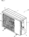
- Fig. 1 is a perspective view illustrating an outdoor unit of an air-conditioning apparatus and the outdoor unit is viewed from the front.
- Fig. 2 is an exploded perspective view illustrating the outdoor unit of an air-conditioning apparatus and the outdoor unit is viewed from the front.
- Fig. 3 is a perspective view illustrating the outdoor unit of an air-conditioning apparatus and the outdoor unit is viewed from the rear.
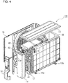
- Fig. 4 is an exploded perspective view illustrating the outdoor unit of an air-conditioning apparatus and the outdoor unit is viewed from the rear.
- the outdoor unit 110 of an air-conditioning apparatus illustrated in Fig. 1 to Fig. 4 includes a housing 1 that forms the outline of the outdoor unit 110.
- the housing 1 includes a front-side-surface panel 10, a right-side-surface panel 11, a bottom-surface panel 12, and a top-surface panel 13.
- the front-side-surface panel 10 is, for example, a part that has an L shape and forms the front side surface and the left side surface of the housing 1.
- the front-side-surface panel 10 has an air outlet that has a circular shape, and a fan guard 10a is attached to the front-side-surface panel 10 in such a manner as to cover the air outlet.
- the outdoor unit 110 of an air-conditioning apparatus has a structure in which leg portions 12a that are attached to the lower surface of the bottom-surface panel 12 are to be fixed at a location, so that the outdoor unit 110 is stably installed at the location.
- Fig. 5 is a perspective view illustrating an internal structure of the outdoor unit with no components illustrated other than a heat exchanger.
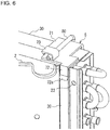
- Fig. 6 is an enlarged view of the portion A illustrated in Fig. 5 .
- Fig. 7 is an enlarged view of the portion A illustrated in Fig. 5 and the portion A is viewed in the transverse direction.
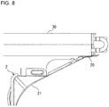
- Fig. 8 is an enlarged view of the portion A and the peripheral portion illustrated in Fig. 5 and the portion A and the peripheral portion are viewed in plan. Note that a holder 5 that is illustrated in Fig. 5 is not illustrated in Fig. 8 .
- the interior of the housing 1 is partitioned into an air-sending device chamber 3 and a machine chamber 4 by a partition plate 2 that extends from the front surface toward the rear surface.
- the partition plate 2 is curved toward the right side surface at a position partway along the partition plate 2 from the front surface toward the rear surface, and as illustrated in Fig. 6 to Fig. 8 , a flat portion 20 that extends along a side surface of a heat exchanger 30 is formed at a terminal portion of a curved surface 21.
- the flat portion 20 has a flat surface that is in contact with the front side surface of the heat exchanger 30 and is joined to the heat exchanger 30 by screwing a shaft portion of a fastening part, such as a screw, into a through hole 22 that is provided in an end portion of the flat portion 20.
- the partition plate 2 is formed to have a shape that corresponds to the width dimension of the heat exchanger 30, and the shape of the partition plate 2 differs for each of various outdoor units.
- the heat exchanger 30, a propeller fan 32, a motor 33, and a motor mounting table 34 are disposed in the air-sending device chamber 3.
- the motor mounting table 34 is a part that holds the motor 33 to which the propeller fan 32 is attached, and the motor mounting table 34 is disposed in front of the heat exchanger 30.
- the outdoor unit 110 is configured in such a manner that, as the propeller fan 32 operates, air that has passed through the heat exchanger 30 is introduced into the outdoor unit 110, passes through the propeller fan 32, and is discharged to the front of the outdoor unit 110.
- the heat exchanger 30 has a two-row structure and extends from an end portion located at the rear surface of the housing 1 to an end portion located at the left side surface of the housing 1.
- the width dimension of the heat exchanger 30, which has a two-row structure is about 44 mm.
- a holder 5 that is made of a synthetic resin and that accommodates a temperature-measurement unit 8 configured to measure the temperature of air outside the housing 1 is mounted on an upper left portion of the rear surface of the heat exchanger 30.
- the temperature-measurement unit 8 includes, for example, a thermistor.
- a compressor 40, a refrigerant pipe 41, an electrical-component unit 42, and a power-supply unit 43 are disposed in the machine chamber 4.
- the compressor 40 is placed on the upper surface of the bottom-surface panel 12 and compresses refrigerant sent from an indoor unit.
- the refrigerant compressed by the compressor 40 is sent to the heat exchanger 30 through the refrigerant pipe 41.
- the electrical-component unit 42 includes a control board and other components and is used for, for example, supplying power to each of the components arranged in the outdoor unit 110.
- the power-supply unit 43 has a configuration in which a terminal block that connects the outdoor unit 110 and the indoor unit to each other is fixed to a power board by using, for example, screws. As illustrated in Fig. 2 and Fig. 4 , the power-supply unit 43 communicates with the outside through an opening 11a that is provided in the right-side-surface panel 11, and as illustrated in Fig. 1 , the power-supply unit 43 is covered with a protective cover 14 that is attached to the outer surface of the right-side-surface panel 11 so that the power-supply unit 43 is protected against dust or water.
- Fig. 9 is a perspective view illustrating a holder of the outdoor unit of an air-conditioning apparatus in a state where a cover portion is opened.
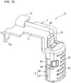
- Fig. 10 is a perspective view illustrating the holder of the outdoor unit of an air-conditioning apparatus in a state where the cover portion is closed.
- the holder 5 includes an accommodating unit 6 that accommodates the temperature-measurement unit 8, and a hook unit 7 that is formed continuous with the accommodating unit 6 and that extends across the top surface of the heat exchanger 30 and is hooked to the flat portion 20.
- the accommodating unit 6 includes a main-body portion 60 that is formed in a recessed manner and that has a base 62 to which the temperature-measurement unit 8 is attached and a cover portion 61 that is pivotally hinged to the lower end of the main-body portion 60.
- a hook 63 is formed on each of the two side edges of the main-body portion 60 and projects toward the cover portion 61.
- a latch hole 64 is provided in each of the two side edges of the cover portion 61 in such a manner that the hooks 63 are latched into the latch holes 64.
- the temperature-measurement unit 8 can be accommodated in the accommodating unit 6 by pivoting the cover portion 61 and latching the hooks 63 into the latch holes 64.
- an operation of attaching or detaching the temperature-measurement unit 8 can be performed by unlatching the hooks 63 from the latch holes 64 and pivoting the cover portion 61 to open the main-body portion 60 while the holder 5 is kept mounted on the heat exchanger 30.
- a through hole is provided in the top surface of the accommodating unit 6 in such a manner that a lead wire 80 of the temperature-measurement unit 8, which is accommodated in the accommodating unit 6, passes through the through hole to the outside.
- a plurality of slit-shaped ventilation holes (not illustrated) that are vertically long or horizontally long are provided in the main-body portion 60.
- a plurality of slit-shaped ventilation holes 65 that are horizontally long are provided in the cover portion 61. Wind that enters from the ventilation holes 65 of the cover portion 61 passes through the interior of the accommodating unit 6 and is suctioned into the heat exchanger 30 through the ventilation holes of the main-body portion 60.
- the hook unit 7 includes an extended-surface portion 70 that extends from the accommodating unit 6 and that is in contact with the rear surface of the heat exchanger 30, a top-surface portion 71 that extends and is bent from an end portion of the extended-surface portion 70 and is placed on the top surface of the heat exchanger 30, and a hook portion 72 that extends and is bent from an end portion of the top-surface portion 71 and is hooked to the flat portion 20.
- the top-surface portion 71 has a length that is approximately the same as the width dimension of the heat exchanger 30 having a two-row structure.
- a recess 70a is formed in the extended-surface portion 70, and the lead wire 80 of the temperature-measurement unit 8 that is protected by a protective tube is fitted into the recess 70a and is fixed in place.
- An L-shaped guide piece 73 that holds the lead wire 80 of the temperature-measurement unit 8 is provided on the top surface of the top-surface portion 71.
- the hook portion 72 has an end portion 72a that is inclined outward. This configuration causes the end portion 72a of the hook portion 72 to be used as a guide portion when the holder 5 is mounted onto the heat exchanger 30.
- the holder 5 is mounted on the heat exchanger 30, which has a two-row structure, in such a manner that the hook unit 7 extends across the top surface of the heat exchanger 30 and is hooked onto the flat portion 20.
- the holder 5 is assembled in such a manner that the rear surface of the heat exchanger 30 and the flat portion 20 are sandwiched by the extended-surface portion 70 and the hook portion 72 and is positioned in such a manner that the top-surface portion 71 is in contact with the upper end edge of the flat portion 20 and the top surface of the heat exchanger 30.
- the end portion 72a of the hook portion 72 is used as the guide portion that guides the holder 5 toward the flat portion 20 when the holder 5 is mounted onto the heat exchanger 30.
- the configuration is not limited to this description.
- the holder 5 may be mounted onto the heat exchanger 30 by hooking the hook portion 72 onto the front side surface of the heat exchanger 30.
- Fig. 11 is a perspective view illustrating an internal structure of an outdoor unit of an air-conditioning apparatus according to the present embodiment with no components illustrated other than a heat exchanger.
- Fig. 12 is an enlarged view of the portion B illustrated in Fig. 11 .
- Fig. 13 is an enlarged view of the portion B illustrated in Fig. 11 and the portion B is viewed in the transverse direction.
- Fig. 14 is an enlarged view of the portion B and the peripheral portion illustrated in Fig. 11 and the portion B and the peripheral portion are viewed in plan.
- the heat exchanger 31 having a single-row structure extends from the end portion located at the rear surface of the housing 1 to the end portion located at the left side surface of the housing 1.
- the width dimension of the heat exchanger 31, which has a single-row structure is about 22 mm.
- a partition plate 9 that is used in the outdoor unit 100 of an air-conditioning apparatus includes a curved surface 93 that is curved toward the right side surface at a position partway along the partition plate 9 from the front surface toward the rear surface.
- the partition plate 9 includes a first flat portion 90 that is formed at a terminal portion of the curved surface 93 with a space S provided between the first flat portion 90 and the heat exchanger 31 and that extends in the longitudinal direction of the heat exchanger 31, and a second flat portion 91 that projects from a side edge portion of the first flat portion 90 toward the heat exchanger 31.
- the partition plate 9 may be formed through adjusting the size of the second flat portion 91, so that the space S having a desired size can be provided between the first flat portion 90 and the heat exchanger 31.
- the holder 5 that is the same as the holder 5 used for the outdoor unit 110 of an air-conditioning apparatus, which includes the heat exchanger 30 having a two-row structure, can be used for the outdoor unit 100 of an air-conditioning apparatus, which includes the heat exchanger 31 having a single-row structure.
- the partition plate 9 includes a third flat portion 92 that projects from a side edge portion of the second flat portion 91 in the longitudinal direction of the heat exchanger 31.
- the third flat portion 92 is in contact with the front side surface of the heat exchanger 31 and is joined to the heat exchanger 31 by screwing a shaft portion of a fastening part, such as a screw, into a through hole 94.
- the partition plate 9 may have a different configuration with which the partition plate 9 is joined to the heat exchanger 31 without the third flat portion 92.
- the holder 5 is mounted on the rear surface of the heat exchanger 31, which has a single-row structure, in such a manner that the hook unit 7 extends across the top surface of the heat exchanger 31 and is hooked onto the first flat portion 90. More specifically, the holder 5 is assembled in such a manner that the rear surface of the heat exchanger 31 and the first flat portion 90 are sandwiched by the extended-surface portion 70 and the hook portion 72 and is positioned in such a manner that the top-surface portion 71 is in contact with the upper end edge of the first flat portion 90 and the top surface of the heat exchanger 31. Note that the end portion 72a of the hook portion 72 is used as a guide portion when the holder 5 is mounted onto the heat exchanger 31.
- the partition plate 9 may be formed through adjusting the length of the second flat portion 91, so that a holder that is the same as a holder used for one outdoor unit of an air-conditioning apparatus that includes a heat exchanger having a three-row structure can also be used for another outdoor unit of an air-conditioning apparatus that includes a heat exchanger having a single-row structure.
- a holder that is the same as a holder used for one outdoor unit of an air-conditioning apparatus that includes a heat exchanger having a single-row structure can be used for another outdoor unit of an air-conditioning apparatus that includes a heat exchanger having a single-row structure and having a width dimension different from that of the heat exchanger included in the one outdoor unit.
- the housing 1 that forms the outline of the outdoor unit 100
- the partition plate 9 that extends from the front surface toward the rear surface of the housing 1 and that partitions the interior of the housing 1 into the air-sending device chamber 3 and the machine chamber 4
- the heat exchanger 31 that is disposed in the air-sending device chamber 3 and along the end portion located at the rear surface of the housing 1
- the holder 5 that is mounted on the heat exchanger 31 and that accommodates the temperature-measurement unit 8 configured to measure the outside air temperature.
- the partition plate 9 includes the first flat portion 90 that is disposed with the space S provided between the rear surface of the first flat portion 90 and the heat exchanger 31 and that extends in the longitudinal direction of the heat exchanger 31, and the second flat portion 91 that projects from the side edge portion of the first flat portion 90 toward the heat exchanger 31.
- the holder 5 includes the accommodating unit 6 that accommodates the temperature-measurement unit 8, and the hook unit 7 that is formed continuous with the accommodating unit 6 and that extends across the top surface of the heat exchanger 31 and is hooked to the first flat portion 90.
- the partition plate 9 may be formed through adjusting the length of the second flat portion 91, so that the space S between the first flat portion 90 and the heat exchanger 31 can fit the shape of the holder 5, and thus, the outdoor unit 100 of an air-conditioning apparatus according to the present embodiment can use the holder 5 that is the same as the holder 5 used for the outdoor unit 110, which includes the heat exchanger 30 having a width dimension different from the width dimension of the heat exchanger 31.
- the outdoor unit 100 of an air-conditioning apparatus according to the present embodiment when the holders 5 are manufactured, only a few manufacturing molds therefore need to be prepared for the shapes of the holders 5, and the manufacturing costs can be kept low. In addition, the burden of managing different types of the holders 5 by classifying the holders 5 by their types can be reduced.
- the partition plate 9 further includes the third flat portion 92 that projects from the side edge portion of the second flat portion 91 in the longitudinal direction of the heat exchanger 31.
- the partition plate 9 can be fixed in place by bringing the third flat portion 92 into contact with the heat exchanger 31 and joining the third flat portion 92 and the heat exchanger 31 to each other by using a fastening part, such as a screw.
- the hook unit 7 of the holder 5 includes the extended-surface portion 70 that extends from the accommodating unit 6 and that is in contact with the rear surface of the heat exchanger 31, the top-surface portion 71 that extends and is bent from the end portion of the extended-surface portion 70 and is placed on the top surface of the heat exchanger 31, and the hook portion 72 that extends and is bent from the end portion of the top-surface portion 71 and hooked to the first flat portion 90.
- the hook portion 72 has the end portion 72a, which is inclined outward.
- the end portion 72a of the hook portion 72 is used as a guide portion that guides the holder 5 toward the first flat portion 90 when the holder 5 is mounted onto the heat exchanger 31, and this configuration facilitates an operation of mounting the holder 5, so that the operational efficiency can be improved.
Landscapes
- Engineering & Computer Science (AREA)
- Chemical & Material Sciences (AREA)
- Combustion & Propulsion (AREA)
- Mechanical Engineering (AREA)
- General Engineering & Computer Science (AREA)
- Other Air-Conditioning Systems (AREA)
- Air Conditioning Control Device (AREA)
Abstract
Description
- The present invention relates to an outdoor unit of an air-conditioning apparatus provided with a holder that accommodates a temperature-measurement unit that measures the outside air temperature.
- There is known some outdoor unit of an air-conditioning apparatus provided with a holder that accommodates a temperature-measurement unit that measures the outside air temperature. For example, Patent Literature 1 discloses a holder mounted onto a heat exchanger that has a single-row structure or a multi-row structure and that is disposed inside a housing that forms an outline of an outdoor unit and the holder extends along an end portion at the rear surface of the housing. This holder includes a main body portion that accommodates a thermistor that is the temperature-measurement unit and a cover portion that is pivotally hinged to the main body portion. The main body portion includes a hook unit that engages the heat exchanger by sandwiching an upper end portion of the heat exchanger in a front-rear direction.
- Patent Literature 1: Japanese Unexamined Patent Application Publication No.
2007-147205 - In a configuration, such as the configuration of the holder disclosed in Patent Literature 1, in which a hook unit engages a heat exchanger by sandwiching an upper end portion of the heat exchanger in the front-rear direction, the dimensions of the hook unit are specified in accordance with the width dimension of the heat exchanger, and thus, the hook unit cannot be mounted on a heat exchanger having a different width dimension. In other words, in some outdoor units of air-conditioning apparatuses, for example, a holder used for an outdoor unit of an air-conditioning apparatus that includes a heat exchanger having a two-row structure cannot be applied to another outdoor unit of an air-conditioning apparatus that includes a heat exchanger having a single-row structure, and consequently, it is necessary to manufacture a holder for each outdoor unit in such a manner that the dimensions of the holder correspond to the width dimension of a heat exchanger included in the outdoor unit. Thus, for some outdoor units of air-conditioning apparatuses, it is necessary to prepare a manufacturing mold for each holder shape, and the manufacturing costs may increase. In addition, it is burdensome to manage different types of holders by classifying the holders by their types, and this management operation is a heavy burden for an operator.
- The present invention has been made to solve such problems described above, and it is an object of the present invention to provide an outdoor unit of an air-conditioning apparatus capable of using a holder that is the same as a holder used for another outdoor unit that includes a heat exchanger having a width dimension different from the width dimension of a heat exchanger included in the outdoor unit. Solution to Problem
- An outdoor unit of an air-conditioning apparatus according to an embodiment of the present invention includes a housing forming an outline of the outdoor unit, a partition plate extending from a front surface of the housing toward a rear surface of the housing and partitioning an interior of the housing into an air-sending device chamber and a machine chamber, a heat exchanger disposed in the air-sending device chamber and along an end portion located at the rear surface of the housing, and a holder mounted on the heat exchanger and accommodating a temperature-measurement unit configured to measure an outside air temperature. The partition plate includes a first flat portion disposed with a space between a rear surface of the first flat portion and the heat exchanger and extending in a longitudinal direction of the heat exchanger, and a second flat portion projecting from a side edge portion of the first flat portion toward the heat exchanger. The holder includes an accommodating unit holding the temperature-measurement unit, and a hook unit formed continuous with the accommodating unit, the hook unit extending across a top surface of the heat exchanger and being hooked to the first flat portion.
- According to an embodiment of the present invention, a partition plate may be formed through adjusting the length of a second flat portion, so that the space between a first flat portion and a heat exchanger can fit the shape of a holder, and thus, an outdoor unit can use a holder the same as a holder that is used for another outdoor unit including a heat exchanger whose width dimension is different from the width dimension of a heat exchanger included in the outdoor unit. Brief Description of Drawings
-
- [
Fig. 1] Fig. 1 is a perspective view illustrating an outdoor unit of an air-conditioning apparatus and the outdoor unit is viewed from the front. - [
Fig. 2] Fig. 2 is an exploded perspective view illustrating the outdoor unit of an air-conditioning apparatus and the outdoor unit is viewed from the front. - [
Fig. 3] Fig. 3 is a perspective view illustrating the outdoor unit of an air-conditioning apparatus and the outdoor unit is viewed from the rear. - [
Fig. 4] Fig. 4 is an exploded perspective view illustrating the outdoor unit of an air-conditioning apparatus and the outdoor unit is viewed from the rear. - [
Fig. 5] Fig. 5 is a perspective view illustrating an internal structure of the outdoor unit with no components illustrated other than a heat exchanger. - [
Fig. 6] Fig. 6 is an enlarged view of the portion A illustrated inFig. 5 . - [
Fig. 7] Fig. 7 is an enlarged view of the portion A illustrated inFig. 5 and the portion A is viewed in a transverse direction. - [
Fig. 8] Fig. 8 is an enlarged view of the portion A and the peripheral portion illustrated inFig. 5 and the portion A and the peripheral portion are viewed in plan. - [
Fig. 9] Fig. 9 is a perspective view illustrating a holder of the outdoor unit of an air-conditioning apparatus in a state where a cover portion is opened. - [
Fig. 10] Fig. 10 is a perspective view illustrating the holder of the outdoor unit of an air-conditioning apparatus in a state where the cover portion is closed. - [
Fig. 11] Fig. 11 is a perspective view illustrating an internal structure of the outdoor unit of an air-conditioning apparatus according to the present embodiment with no components illustrated other than the heat exchanger. - [
Fig. 12] Fig. 12 is an enlarged view of the portion B illustrated inFig. 11 . - [
Fig. 13] Fig. 13 is an enlarged view of the portion B illustrated inFig. 11 and the portion B is viewed in the transverse direction. - [
Fig. 14] Fig. 14 is an enlarged view of the portion B and the peripheral portion illustrated inFig. 11 and the portion B and the peripheral portion are viewed in plan. Description of Embodiment - An embodiment of the present invention will be described below with reference to the drawings. Note that, in the drawings, portions that are the same as each other or that correspond to each other are denoted by the same reference sign, and descriptions of the portions will be suitably omitted or simplified. In addition, shape, size, arrangement, and other characteristics in the configurations illustrated in the drawings can be suitably changed within the scope of the present invention.
- An outdoor unit of an air-conditioning apparatus according to the embodiment of the present invention is configured to be capable of using a holder the same as the holder of a temperature-measurement unit that is used for another outdoor unit including a heat exchanger whose width dimension is different from the width dimension of a heat exchanger included in the outdoor unit according to the present embodiment. For this reason, in the present embodiment, a case will be described as an example in which a holder that is the same as the holder used for an
outdoor unit 110 of an air-conditioning apparatus that includes a heat exchanger having a two-row structure is used for anoutdoor unit 100 of an air-conditioning apparatus that includes a heat exchanger having a single-row structure. - First, a common structure of the
outdoor unit 100 of an air-conditioning apparatus according to the present embodiment will be described with reference to theoutdoor unit 110 of an air-conditioning apparatus that is illustrated inFig. 1 to Fig. 10 and that includes the heat exchanger having a two-row structure.Fig. 1 is a perspective view illustrating an outdoor unit of an air-conditioning apparatus and the outdoor unit is viewed from the front.Fig. 2 is an exploded perspective view illustrating the outdoor unit of an air-conditioning apparatus and the outdoor unit is viewed from the front.Fig. 3 is a perspective view illustrating the outdoor unit of an air-conditioning apparatus and the outdoor unit is viewed from the rear.Fig. 4 is an exploded perspective view illustrating the outdoor unit of an air-conditioning apparatus and the outdoor unit is viewed from the rear. - The
outdoor unit 110 of an air-conditioning apparatus illustrated inFig. 1 to Fig. 4 includes a housing 1 that forms the outline of theoutdoor unit 110. As an example, the housing 1 includes a front-side-surface panel 10, a right-side-surface panel 11, a bottom-surface panel 12, and a top-surface panel 13. The front-side-surface panel 10 is, for example, a part that has an L shape and forms the front side surface and the left side surface of the housing 1. The front-side-surface panel 10 has an air outlet that has a circular shape, and afan guard 10a is attached to the front-side-surface panel 10 in such a manner as to cover the air outlet. Theoutdoor unit 110 of an air-conditioning apparatus has a structure in whichleg portions 12a that are attached to the lower surface of the bottom-surface panel 12 are to be fixed at a location, so that theoutdoor unit 110 is stably installed at the location. -
Fig. 5 is a perspective view illustrating an internal structure of the outdoor unit with no components illustrated other than a heat exchanger.Fig. 6 is an enlarged view of the portion A illustrated inFig. 5 .Fig. 7 is an enlarged view of the portion A illustrated inFig. 5 and the portion A is viewed in the transverse direction.Fig. 8 is an enlarged view of the portion A and the peripheral portion illustrated inFig. 5 and the portion A and the peripheral portion are viewed in plan. Note that aholder 5 that is illustrated inFig. 5 is not illustrated inFig. 8 . As illustrated inFig. 5 , the interior of the housing 1 is partitioned into an air-sending device chamber 3 and amachine chamber 4 by apartition plate 2 that extends from the front surface toward the rear surface. - As illustrated in
Fig. 5 , thepartition plate 2 is curved toward the right side surface at a position partway along thepartition plate 2 from the front surface toward the rear surface, and as illustrated inFig. 6 to Fig. 8 , aflat portion 20 that extends along a side surface of aheat exchanger 30 is formed at a terminal portion of acurved surface 21. Theflat portion 20 has a flat surface that is in contact with the front side surface of theheat exchanger 30 and is joined to theheat exchanger 30 by screwing a shaft portion of a fastening part, such as a screw, into athrough hole 22 that is provided in an end portion of theflat portion 20. Thepartition plate 2 is formed to have a shape that corresponds to the width dimension of theheat exchanger 30, and the shape of thepartition plate 2 differs for each of various outdoor units. - As illustrated in
Fig. 2 , theheat exchanger 30, apropeller fan 32, amotor 33, and a motor mounting table 34 are disposed in the air-sending device chamber 3. The motor mounting table 34 is a part that holds themotor 33 to which thepropeller fan 32 is attached, and the motor mounting table 34 is disposed in front of theheat exchanger 30. Theoutdoor unit 110 is configured in such a manner that, as thepropeller fan 32 operates, air that has passed through theheat exchanger 30 is introduced into theoutdoor unit 110, passes through thepropeller fan 32, and is discharged to the front of theoutdoor unit 110. As a result, in theoutdoor unit 110, for example, during the period when an air-cooling operation is performed, refrigerant is cooled by the air in theheat exchanger 30, and the air that has passed through theheat exchanger 30 is heated by heat exchange with the refrigerant. - As illustrated in
Fig. 2 ,Fig. 4 , andFig. 5 , theheat exchanger 30 has a two-row structure and extends from an end portion located at the rear surface of the housing 1 to an end portion located at the left side surface of the housing 1. As an example, the width dimension of theheat exchanger 30, which has a two-row structure, is about 44 mm. As illustrated inFig. 3 ,Fig. 4 ,Fig. 6 , andFig. 7 , aholder 5 that is made of a synthetic resin and that accommodates a temperature-measurement unit 8 configured to measure the temperature of air outside the housing 1 is mounted on an upper left portion of the rear surface of theheat exchanger 30. The temperature-measurement unit 8 includes, for example, a thermistor. - As illustrated in
Fig. 2 andFig. 4 , acompressor 40, arefrigerant pipe 41, an electrical-component unit 42, and a power-supply unit 43 are disposed in themachine chamber 4. Thecompressor 40 is placed on the upper surface of the bottom-surface panel 12 and compresses refrigerant sent from an indoor unit. The refrigerant compressed by thecompressor 40 is sent to theheat exchanger 30 through therefrigerant pipe 41. The electrical-component unit 42 includes a control board and other components and is used for, for example, supplying power to each of the components arranged in theoutdoor unit 110. The power-supply unit 43 has a configuration in which a terminal block that connects theoutdoor unit 110 and the indoor unit to each other is fixed to a power board by using, for example, screws. As illustrated inFig. 2 andFig. 4 , the power-supply unit 43 communicates with the outside through anopening 11a that is provided in the right-side-surface panel 11, and as illustrated inFig. 1 , the power-supply unit 43 is covered with aprotective cover 14 that is attached to the outer surface of the right-side-surface panel 11 so that the power-supply unit 43 is protected against dust or water. - Next, the specific configuration of the
holder 5 will be described with reference toFig. 9 andFig. 10 .Fig. 9 is a perspective view illustrating a holder of the outdoor unit of an air-conditioning apparatus in a state where a cover portion is opened.Fig. 10 is a perspective view illustrating the holder of the outdoor unit of an air-conditioning apparatus in a state where the cover portion is closed. As illustrated inFig. 9 andFig. 10 , theholder 5 includes anaccommodating unit 6 that accommodates the temperature-measurement unit 8, and ahook unit 7 that is formed continuous with theaccommodating unit 6 and that extends across the top surface of theheat exchanger 30 and is hooked to theflat portion 20. - The
accommodating unit 6 includes a main-body portion 60 that is formed in a recessed manner and that has a base 62 to which the temperature-measurement unit 8 is attached and acover portion 61 that is pivotally hinged to the lower end of the main-body portion 60. Ahook 63 is formed on each of the two side edges of the main-body portion 60 and projects toward thecover portion 61. In contrast, alatch hole 64 is provided in each of the two side edges of thecover portion 61 in such a manner that thehooks 63 are latched into the latch holes 64. As illustrated inFig. 10 , the temperature-measurement unit 8 can be accommodated in theaccommodating unit 6 by pivoting thecover portion 61 and latching thehooks 63 into the latch holes 64. In other words, an operation of attaching or detaching the temperature-measurement unit 8 can be performed by unlatching thehooks 63 from the latch holes 64 and pivoting thecover portion 61 to open the main-body portion 60 while theholder 5 is kept mounted on theheat exchanger 30. Note that a through hole is provided in the top surface of theaccommodating unit 6 in such a manner that alead wire 80 of the temperature-measurement unit 8, which is accommodated in theaccommodating unit 6, passes through the through hole to the outside. - A plurality of slit-shaped ventilation holes (not illustrated) that are vertically long or horizontally long are provided in the main-
body portion 60. In addition, a plurality of slit-shaped ventilation holes 65 that are horizontally long are provided in thecover portion 61. Wind that enters from the ventilation holes 65 of thecover portion 61 passes through the interior of theaccommodating unit 6 and is suctioned into theheat exchanger 30 through the ventilation holes of the main-body portion 60. - The
hook unit 7 includes an extended-surface portion 70 that extends from theaccommodating unit 6 and that is in contact with the rear surface of theheat exchanger 30, a top-surface portion 71 that extends and is bent from an end portion of the extended-surface portion 70 and is placed on the top surface of theheat exchanger 30, and ahook portion 72 that extends and is bent from an end portion of the top-surface portion 71 and is hooked to theflat portion 20. The top-surface portion 71 has a length that is approximately the same as the width dimension of theheat exchanger 30 having a two-row structure. - A
recess 70a is formed in the extended-surface portion 70, and thelead wire 80 of the temperature-measurement unit 8 that is protected by a protective tube is fitted into therecess 70a and is fixed in place. An L-shapedguide piece 73 that holds thelead wire 80 of the temperature-measurement unit 8 is provided on the top surface of the top-surface portion 71. - The
hook portion 72 has anend portion 72a that is inclined outward. This configuration causes theend portion 72a of thehook portion 72 to be used as a guide portion when theholder 5 is mounted onto theheat exchanger 30. - As illustrated in
Fig. 6 andFig. 7 , theholder 5 is mounted on theheat exchanger 30, which has a two-row structure, in such a manner that thehook unit 7 extends across the top surface of theheat exchanger 30 and is hooked onto theflat portion 20. In other words, theholder 5 is assembled in such a manner that the rear surface of theheat exchanger 30 and theflat portion 20 are sandwiched by the extended-surface portion 70 and thehook portion 72 and is positioned in such a manner that the top-surface portion 71 is in contact with the upper end edge of theflat portion 20 and the top surface of theheat exchanger 30. In this case, theend portion 72a of thehook portion 72 is used as the guide portion that guides theholder 5 toward theflat portion 20 when theholder 5 is mounted onto theheat exchanger 30. - Note that, in the embodiment illustrated in the drawings, although a configuration has been described in which the
holder 5 is mounted onto theheat exchanger 30 by hooking thehook portion 72 onto theflat portion 20 of thepartition plate 2, the configuration is not limited to this description. Theholder 5 may be mounted onto theheat exchanger 30 by hooking thehook portion 72 onto the front side surface of theheat exchanger 30. - Next, the
outdoor unit 100 of an air-conditioning apparatus that includes aheat exchanger 31 that has a single-row structure will be described with reference toFig. 11 to Fig. 14 .Fig. 11 is a perspective view illustrating an internal structure of an outdoor unit of an air-conditioning apparatus according to the present embodiment with no components illustrated other than a heat exchanger.Fig. 12 is an enlarged view of the portion B illustrated inFig. 11 .Fig. 13 is an enlarged view of the portion B illustrated inFig. 11 and the portion B is viewed in the transverse direction.Fig. 14 is an enlarged view of the portion B and the peripheral portion illustrated inFig. 11 and the portion B and the peripheral portion are viewed in plan. - As illustrated in
Fig. 11 to Fig. 13 , in theoutdoor unit 100 of an air-conditioning apparatus, theheat exchanger 31 having a single-row structure extends from the end portion located at the rear surface of the housing 1 to the end portion located at the left side surface of the housing 1. As an example, the width dimension of theheat exchanger 31, which has a single-row structure, is about 22 mm. - As illustrated in
Fig. 11 andFig. 14 , apartition plate 9 that is used in theoutdoor unit 100 of an air-conditioning apparatus includes acurved surface 93 that is curved toward the right side surface at a position partway along thepartition plate 9 from the front surface toward the rear surface. Thepartition plate 9 includes a firstflat portion 90 that is formed at a terminal portion of thecurved surface 93 with a space S provided between the firstflat portion 90 and theheat exchanger 31 and that extends in the longitudinal direction of theheat exchanger 31, and a secondflat portion 91 that projects from a side edge portion of the firstflat portion 90 toward theheat exchanger 31. Thepartition plate 9 may be formed through adjusting the size of the secondflat portion 91, so that the space S having a desired size can be provided between the firstflat portion 90 and theheat exchanger 31. In other words, in the present embodiment, as the space S that corresponds to the width dimension of the heat exchanger having a single-row structure can be provided by the secondflat portion 91, theholder 5 that is the same as theholder 5 used for theoutdoor unit 110 of an air-conditioning apparatus, which includes theheat exchanger 30 having a two-row structure, can be used for theoutdoor unit 100 of an air-conditioning apparatus, which includes theheat exchanger 31 having a single-row structure. - In addition, as illustrated in
Fig. 12 andFig. 14 , thepartition plate 9 includes a thirdflat portion 92 that projects from a side edge portion of the secondflat portion 91 in the longitudinal direction of theheat exchanger 31. The thirdflat portion 92 is in contact with the front side surface of theheat exchanger 31 and is joined to theheat exchanger 31 by screwing a shaft portion of a fastening part, such as a screw, into a throughhole 94. Note that thepartition plate 9 may have a different configuration with which thepartition plate 9 is joined to theheat exchanger 31 without the thirdflat portion 92. - As illustrated in
Fig. 12 andFig. 13 , theholder 5 is mounted on the rear surface of theheat exchanger 31, which has a single-row structure, in such a manner that thehook unit 7 extends across the top surface of theheat exchanger 31 and is hooked onto the firstflat portion 90. More specifically, theholder 5 is assembled in such a manner that the rear surface of theheat exchanger 31 and the firstflat portion 90 are sandwiched by the extended-surface portion 70 and thehook portion 72 and is positioned in such a manner that the top-surface portion 71 is in contact with the upper end edge of the firstflat portion 90 and the top surface of theheat exchanger 31. Note that theend portion 72a of thehook portion 72 is used as a guide portion when theholder 5 is mounted onto theheat exchanger 31. - Note that, in the embodiment illustrated in the drawings, although a case has been described as an example in which the
holder 5 that is the same as theholder 5 used for theoutdoor unit 110 of an air-conditioning apparatus, which includes theheat exchanger 30 having a two-row structure, can be used for theoutdoor unit 100 of an air-conditioning apparatus, which includes theheat exchanger 31 having a single-row structure, the configuration is not limited to this case. In theoutdoor unit 100 of an air-conditioning apparatus according to the present embodiment, thepartition plate 9 may be formed through adjusting the length of the secondflat portion 91, so that a holder that is the same as a holder used for one outdoor unit of an air-conditioning apparatus that includes a heat exchanger having a three-row structure can also be used for another outdoor unit of an air-conditioning apparatus that includes a heat exchanger having a single-row structure. In addition, a holder that is the same as a holder used for one outdoor unit of an air-conditioning apparatus that includes a heat exchanger having a single-row structure can be used for another outdoor unit of an air-conditioning apparatus that includes a heat exchanger having a single-row structure and having a width dimension different from that of the heat exchanger included in the one outdoor unit. - As described above, with the
outdoor unit 100 of an air-conditioning apparatus of the present embodiment, the housing 1 that forms the outline of theoutdoor unit 100, thepartition plate 9 that extends from the front surface toward the rear surface of the housing 1 and that partitions the interior of the housing 1 into the air-sendingdevice chamber 3 and themachine chamber 4, theheat exchanger 31 that is disposed in the air-sendingdevice chamber 3 and along the end portion located at the rear surface of the housing 1, and theholder 5 that is mounted on theheat exchanger 31 and that accommodates the temperature-measurement unit 8 configured to measure the outside air temperature. Thepartition plate 9 includes the firstflat portion 90 that is disposed with the space S provided between the rear surface of the firstflat portion 90 and theheat exchanger 31 and that extends in the longitudinal direction of theheat exchanger 31, and the secondflat portion 91 that projects from the side edge portion of the firstflat portion 90 toward theheat exchanger 31. Theholder 5 includes theaccommodating unit 6 that accommodates the temperature-measurement unit 8, and thehook unit 7 that is formed continuous with theaccommodating unit 6 and that extends across the top surface of theheat exchanger 31 and is hooked to the firstflat portion 90. - Consequently, the
partition plate 9 may be formed through adjusting the length of the secondflat portion 91, so that the space S between the firstflat portion 90 and theheat exchanger 31 can fit the shape of theholder 5, and thus, theoutdoor unit 100 of an air-conditioning apparatus according to the present embodiment can use theholder 5 that is the same as theholder 5 used for theoutdoor unit 110, which includes theheat exchanger 30 having a width dimension different from the width dimension of theheat exchanger 31. With theoutdoor unit 100 of an air-conditioning apparatus according to the present embodiment, when theholders 5 are manufactured, only a few manufacturing molds therefore need to be prepared for the shapes of theholders 5, and the manufacturing costs can be kept low. In addition, the burden of managing different types of theholders 5 by classifying theholders 5 by their types can be reduced. - The
partition plate 9 further includes the thirdflat portion 92 that projects from the side edge portion of the secondflat portion 91 in the longitudinal direction of theheat exchanger 31. Thus, in theoutdoor unit 100 of an air-conditioning apparatus according to the present embodiment, thepartition plate 9 can be fixed in place by bringing the thirdflat portion 92 into contact with theheat exchanger 31 and joining the thirdflat portion 92 and theheat exchanger 31 to each other by using a fastening part, such as a screw. - The
hook unit 7 of theholder 5 includes the extended-surface portion 70 that extends from theaccommodating unit 6 and that is in contact with the rear surface of theheat exchanger 31, the top-surface portion 71 that extends and is bent from the end portion of the extended-surface portion 70 and is placed on the top surface of theheat exchanger 31, and thehook portion 72 that extends and is bent from the end portion of the top-surface portion 71 and hooked to the firstflat portion 90. Thehook portion 72 has theend portion 72a, which is inclined outward. Thus, in theoutdoor unit 100 of an air-conditioning apparatus according to the present embodiment, theend portion 72a of thehook portion 72 is used as a guide portion that guides theholder 5 toward the firstflat portion 90 when theholder 5 is mounted onto theheat exchanger 31, and this configuration facilitates an operation of mounting theholder 5, so that the operational efficiency can be improved. - Although the present invention has been described above with reference to the embodiment, the present invention is not limited to the configuration according to the above-described embodiment. For example, each of the configurations of the outdoor units of air-conditioning apparatuses that are illustrated in the drawings is an example, and the configuration is not limited to the above-described contents. The configuration can be applied to an outdoor unit of an air-conditioning apparatus that includes other components. In other words, it should be noted that various modifications, applications, and usages that are made as necessary by those skilled in the art are also included in the gist (technical scope) of the present invention. Reference Signs List
- 1
housing 2partition plate 3 air-sendingdevice chamber 4machine chamber 5holder 6accommodating unit 7hook unit 8 temperature-measurement unit 9partition plate 10 front-side-surface panel 10a fan guard 11 right-side-surface panel 11a opening 12 bottom-surface panel 12a leg portion 13 top-surface panel 14protective cover 20flat portion 21curved surface 22 throughhole heat exchanger 32propeller fan 33motor 34 motor mounting table 40compressor 41refrigerant pipe 42 electrical-component unit 43 power-supply unit 60 main-body portion 61cover portion 62base 63hook 64latch hole 65ventilation hole 70 extended-surface 71 top-portion 70a recesssurface portion 72hook portion 72a end portion 73guide piece 80lead wire 90 firstflat portion 91 secondflat portion 92 thirdflat portion 93curved surface 94 throughhole
Claims (3)
- An outdoor unit of an air-conditioning apparatus, the outdoor unit comprising:a housing forming an outline of the outdoor unit;a partition plate extending from a front surface of the housing toward a rear surface of the housing and partitioning an interior of the housing into an air-sending device chamber and a machine chamber;a heat exchanger disposed in the air-sending device chamber and along an end portion located at the rear surface of the housing; anda holder mounted on the heat exchanger and accommodating a temperature-measurement unit configured to measure an outside air temperature,the partition plate includinga first flat portion disposed with a space between a rear surface of the first flat portion and the heat exchanger and extending in a longitudinal direction of the heat exchanger, anda second flat portion projecting from a side edge portion of the first flat portion toward the heat exchanger,the holder includingan accommodating unit holding the temperature-measurement unit, anda hook unit formed continuous with the accommodating unit, the hook unit extending across a top surface of the heat exchanger and being hooked to the first flat portion.
- The outdoor unit of an air-conditioning apparatus of claim 1, wherein the partition plate further includes a third flat portion projecting from a side edge portion of the second flat portion in the longitudinal direction of the heat exchanger.
- The outdoor unit of an air-conditioning apparatus of claim 1 or 2,
wherein the hook unit of the holder includes
an extended-surface portion extending from the accommodating unit, the extended-surface portion being in contact with a rear surface of the heat exchanger,
a top-surface portion extending and being bent from an end portion of the extended-surface portion and placed on the top surface of the heat exchanger, and
a hook portion extending and being bent from an end portion of the top-surface portion and hooked to the first flat portion, and
wherein the hook portion has an end portion that is inclined outward.
Applications Claiming Priority (1)
| Application Number | Priority Date | Filing Date | Title |
|---|---|---|---|
| PCT/JP2017/027074 WO2019021395A1 (en) | 2017-07-26 | 2017-07-26 | Outdoor unit for air conditioner |
Publications (3)
| Publication Number | Publication Date |
|---|---|
| EP3660410A1 true EP3660410A1 (en) | 2020-06-03 |
| EP3660410A4 EP3660410A4 (en) | 2020-08-26 |
| EP3660410B1 EP3660410B1 (en) | 2021-09-29 |
Family
ID=65039549
Family Applications (1)
| Application Number | Title | Priority Date | Filing Date |
|---|---|---|---|
| EP17919377.6A Not-in-force EP3660410B1 (en) | 2017-07-26 | 2017-07-26 | Outdoor unit for air conditioner |
Country Status (5)
| Country | Link |
|---|---|
| US (1) | US11306926B2 (en) |
| EP (1) | EP3660410B1 (en) |
| JP (1) | JP6727442B2 (en) |
| CN (1) | CN110914601B (en) |
| WO (1) | WO2019021395A1 (en) |
Families Citing this family (2)
| Publication number | Priority date | Publication date | Assignee | Title |
|---|---|---|---|---|
| JP7595251B2 (en) * | 2020-05-29 | 2024-12-06 | パナソニックIpマネジメント株式会社 | Air Conditioning Equipment |
| CN115978654B (en) * | 2022-11-30 | 2024-08-16 | 青岛海尔空调器有限总公司 | Outdoor unit for air conditioner and air conditioner |
Family Cites Families (15)
| Publication number | Priority date | Publication date | Assignee | Title |
|---|---|---|---|---|
| JPH0712394A (en) | 1993-06-23 | 1995-01-17 | Matsushita Refrig Co Ltd | How to install the outside air temperature sensor |
| JP3354475B2 (en) * | 1998-02-26 | 2002-12-09 | シャープ株式会社 | Outdoor unit of air conditioner |
| JP3856623B2 (en) * | 2000-06-15 | 2006-12-13 | シャープ株式会社 | Air conditioner outdoor unit |
| JP2003185191A (en) * | 2001-12-20 | 2003-07-03 | Fujitsu General Ltd | Outdoor unit of air conditioner |
| JP2006220361A (en) * | 2005-02-10 | 2006-08-24 | Sanyo Electric Co Ltd | Air conditioner |
| JP4611875B2 (en) * | 2005-11-30 | 2011-01-12 | 三菱電機株式会社 | Air conditioner outdoor unit |
| JP2008121949A (en) * | 2006-11-10 | 2008-05-29 | Matsushita Electric Ind Co Ltd | Air conditioner outdoor unit |
| CN101307933A (en) * | 2007-05-18 | 2008-11-19 | 乐金电子(天津)电器有限公司 | Temperature sensor fixing structure for outdoor set of air-conditioner |
| JP2009174760A (en) * | 2008-01-23 | 2009-08-06 | Daikin Ind Ltd | Outdoor unit |
| JP5213844B2 (en) * | 2009-12-28 | 2013-06-19 | 三菱電機株式会社 | Air conditioner outdoor unit |
| JP5246325B2 (en) * | 2011-12-28 | 2013-07-24 | ダイキン工業株式会社 | Refrigeration unit outdoor unit |
| JP2014047996A (en) * | 2012-09-03 | 2014-03-17 | Hitachi Appliances Inc | Air conditioner |
| CN203404869U (en) * | 2013-07-19 | 2014-01-22 | 广州华凌制冷设备有限公司 | Temperature measurement assembly used for air conditioner outdoor unit and air conditioner outdoor unit provided with temperature measurement assembly |
| JP6387527B2 (en) * | 2015-06-29 | 2018-09-12 | パナソニックIpマネジメント株式会社 | Air conditioner outdoor unit |
| JP6681171B2 (en) * | 2015-10-29 | 2020-04-15 | 東芝キヤリア株式会社 | Air conditioner outdoor unit |
-
2017
- 2017-07-26 EP EP17919377.6A patent/EP3660410B1/en not_active Not-in-force
- 2017-07-26 CN CN201780092482.XA patent/CN110914601B/en not_active Expired - Fee Related
- 2017-07-26 US US16/616,614 patent/US11306926B2/en active Active
- 2017-07-26 JP JP2019532270A patent/JP6727442B2/en not_active Expired - Fee Related
- 2017-07-26 WO PCT/JP2017/027074 patent/WO2019021395A1/en not_active Ceased
Also Published As
| Publication number | Publication date |
|---|---|
| EP3660410A4 (en) | 2020-08-26 |
| CN110914601B (en) | 2021-07-16 |
| JPWO2019021395A1 (en) | 2019-11-07 |
| US11306926B2 (en) | 2022-04-19 |
| WO2019021395A1 (en) | 2019-01-31 |
| JP6727442B2 (en) | 2020-07-22 |
| EP3660410B1 (en) | 2021-09-29 |
| US20200182492A1 (en) | 2020-06-11 |
| CN110914601A (en) | 2020-03-24 |
Similar Documents
| Publication | Publication Date | Title |
|---|---|---|
| US20100193164A1 (en) | Outdoor unit of air conditioner | |
| KR101589027B1 (en) | Outdoor unit of air conditioner | |
| EP3336444B1 (en) | Ceiling-embedded air conditioner | |
| US11131479B2 (en) | Air-conditioning apparatus indoor unit | |
| US11624545B2 (en) | Refrigerator having removable cooling module | |
| EP2520869B1 (en) | Ceiling-mounted air conditioner | |
| US11306926B2 (en) | Outdoor unit of air-conditioning apparatus | |
| JPWO2015125673A1 (en) | Air conditioner | |
| EP2246635A1 (en) | Air flow direction adjusting unit and heat source unit for refrigeration device | |
| CN210511943U (en) | Outdoor machine of air conditioner | |
| KR20150091616A (en) | Outdoor unit for air conditoiner | |
| WO2019207683A1 (en) | Air conditioner outdoor unit | |
| EP3426012B1 (en) | Electric component module and outdoor unit for air conditioner | |
| CN104776500A (en) | Air conditioner | |
| US10833490B2 (en) | Control board | |
| KR20150088152A (en) | Three-way discharge airconditioner | |
| CN217884325U (en) | Accurate refrigeration air supply arrangement | |
| KR200485058Y1 (en) | Low-pressure air conditioning switchgear | |
| JPH1019446A (en) | Showcase | |
| JP6679827B2 (en) | Showcase | |
| JP2003156233A (en) | Outdoor unit of air conditioner | |
| EP3521726A1 (en) | Indoor unit for air conditioning device | |
| US20150034275A1 (en) | Heat exchanging system of vending machine | |
| JP3147725B2 (en) | Switch box installation structure of air conditioner | |
| CN113874663B (en) | Indoor unit of air conditioner and attachment device for indoor unit |
Legal Events
| Date | Code | Title | Description |
|---|---|---|---|
| STAA | Information on the status of an ep patent application or granted ep patent |
Free format text: STATUS: THE INTERNATIONAL PUBLICATION HAS BEEN MADE |
|
| PUAI | Public reference made under article 153(3) epc to a published international application that has entered the european phase |
Free format text: ORIGINAL CODE: 0009012 |
|
| STAA | Information on the status of an ep patent application or granted ep patent |
Free format text: STATUS: REQUEST FOR EXAMINATION WAS MADE |
|
| 17P | Request for examination filed |
Effective date: 20200121 |
|
| AK | Designated contracting states |
Kind code of ref document: A1 Designated state(s): AL AT BE BG CH CY CZ DE DK EE ES FI FR GB GR HR HU IE IS IT LI LT LU LV MC MK MT NL NO PL PT RO RS SE SI SK SM TR |
|
| AX | Request for extension of the european patent |
Extension state: BA ME |
|
| A4 | Supplementary search report drawn up and despatched |
Effective date: 20200727 |
|
| RIC1 | Information provided on ipc code assigned before grant |
Ipc: F24F 1/46 20110101AFI20200721BHEP Ipc: F24F 11/89 20180101ALI20200721BHEP |
|
| DAV | Request for validation of the european patent (deleted) | ||
| DAX | Request for extension of the european patent (deleted) | ||
| REG | Reference to a national code |
Ref country code: DE Ref legal event code: R079 Ref document number: 602017047001 Country of ref document: DE Free format text: PREVIOUS MAIN CLASS: F24F0011300000 Ipc: F24F0001460000 |
|
| GRAP | Despatch of communication of intention to grant a patent |
Free format text: ORIGINAL CODE: EPIDOSNIGR1 |
|
| STAA | Information on the status of an ep patent application or granted ep patent |
Free format text: STATUS: GRANT OF PATENT IS INTENDED |
|
| RIC1 | Information provided on ipc code assigned before grant |
Ipc: F24F 11/89 20180101ALI20210419BHEP Ipc: F24F 1/46 20110101AFI20210419BHEP |
|
| INTG | Intention to grant announced |
Effective date: 20210504 |
|
| GRAS | Grant fee paid |
Free format text: ORIGINAL CODE: EPIDOSNIGR3 |
|
| GRAA | (expected) grant |
Free format text: ORIGINAL CODE: 0009210 |
|
| STAA | Information on the status of an ep patent application or granted ep patent |
Free format text: STATUS: THE PATENT HAS BEEN GRANTED |
|
| AK | Designated contracting states |
Kind code of ref document: B1 Designated state(s): AL AT BE BG CH CY CZ DE DK EE ES FI FR GB GR HR HU IE IS IT LI LT LU LV MC MK MT NL NO PL PT RO RS SE SI SK SM TR |
|
| REG | Reference to a national code |
Ref country code: GB Ref legal event code: FG4D |
|
| REG | Reference to a national code |
Ref country code: DE Ref legal event code: R096 Ref document number: 602017047001 Country of ref document: DE |
|
| REG | Reference to a national code |
Ref country code: CH Ref legal event code: EP Ref country code: AT Ref legal event code: REF Ref document number: 1434532 Country of ref document: AT Kind code of ref document: T Effective date: 20211015 |
|
| REG | Reference to a national code |
Ref country code: IE Ref legal event code: FG4D |
|
| REG | Reference to a national code |
Ref country code: LT Ref legal event code: MG9D |
|
| PG25 | Lapsed in a contracting state [announced via postgrant information from national office to epo] |
Ref country code: LT Free format text: LAPSE BECAUSE OF FAILURE TO SUBMIT A TRANSLATION OF THE DESCRIPTION OR TO PAY THE FEE WITHIN THE PRESCRIBED TIME-LIMIT Effective date: 20210929 Ref country code: BG Free format text: LAPSE BECAUSE OF FAILURE TO SUBMIT A TRANSLATION OF THE DESCRIPTION OR TO PAY THE FEE WITHIN THE PRESCRIBED TIME-LIMIT Effective date: 20211229 Ref country code: NO Free format text: LAPSE BECAUSE OF FAILURE TO SUBMIT A TRANSLATION OF THE DESCRIPTION OR TO PAY THE FEE WITHIN THE PRESCRIBED TIME-LIMIT Effective date: 20211229 Ref country code: RS Free format text: LAPSE BECAUSE OF FAILURE TO SUBMIT A TRANSLATION OF THE DESCRIPTION OR TO PAY THE FEE WITHIN THE PRESCRIBED TIME-LIMIT Effective date: 20210929 Ref country code: SE Free format text: LAPSE BECAUSE OF FAILURE TO SUBMIT A TRANSLATION OF THE DESCRIPTION OR TO PAY THE FEE WITHIN THE PRESCRIBED TIME-LIMIT Effective date: 20210929 Ref country code: HR Free format text: LAPSE BECAUSE OF FAILURE TO SUBMIT A TRANSLATION OF THE DESCRIPTION OR TO PAY THE FEE WITHIN THE PRESCRIBED TIME-LIMIT Effective date: 20210929 Ref country code: FI Free format text: LAPSE BECAUSE OF FAILURE TO SUBMIT A TRANSLATION OF THE DESCRIPTION OR TO PAY THE FEE WITHIN THE PRESCRIBED TIME-LIMIT Effective date: 20210929 |
|
| REG | Reference to a national code |
Ref country code: NL Ref legal event code: MP Effective date: 20210929 |
|
| REG | Reference to a national code |
Ref country code: AT Ref legal event code: MK05 Ref document number: 1434532 Country of ref document: AT Kind code of ref document: T Effective date: 20210929 |
|
| PG25 | Lapsed in a contracting state [announced via postgrant information from national office to epo] |
Ref country code: LV Free format text: LAPSE BECAUSE OF FAILURE TO SUBMIT A TRANSLATION OF THE DESCRIPTION OR TO PAY THE FEE WITHIN THE PRESCRIBED TIME-LIMIT Effective date: 20210929 Ref country code: GR Free format text: LAPSE BECAUSE OF FAILURE TO SUBMIT A TRANSLATION OF THE DESCRIPTION OR TO PAY THE FEE WITHIN THE PRESCRIBED TIME-LIMIT Effective date: 20211230 |
|
| PG25 | Lapsed in a contracting state [announced via postgrant information from national office to epo] |
Ref country code: AT Free format text: LAPSE BECAUSE OF FAILURE TO SUBMIT A TRANSLATION OF THE DESCRIPTION OR TO PAY THE FEE WITHIN THE PRESCRIBED TIME-LIMIT Effective date: 20210929 |
|
| PG25 | Lapsed in a contracting state [announced via postgrant information from national office to epo] |
Ref country code: IS Free format text: LAPSE BECAUSE OF FAILURE TO SUBMIT A TRANSLATION OF THE DESCRIPTION OR TO PAY THE FEE WITHIN THE PRESCRIBED TIME-LIMIT Effective date: 20220129 Ref country code: SK Free format text: LAPSE BECAUSE OF FAILURE TO SUBMIT A TRANSLATION OF THE DESCRIPTION OR TO PAY THE FEE WITHIN THE PRESCRIBED TIME-LIMIT Effective date: 20210929 Ref country code: RO Free format text: LAPSE BECAUSE OF FAILURE TO SUBMIT A TRANSLATION OF THE DESCRIPTION OR TO PAY THE FEE WITHIN THE PRESCRIBED TIME-LIMIT Effective date: 20210929 Ref country code: PT Free format text: LAPSE BECAUSE OF FAILURE TO SUBMIT A TRANSLATION OF THE DESCRIPTION OR TO PAY THE FEE WITHIN THE PRESCRIBED TIME-LIMIT Effective date: 20220131 Ref country code: PL Free format text: LAPSE BECAUSE OF FAILURE TO SUBMIT A TRANSLATION OF THE DESCRIPTION OR TO PAY THE FEE WITHIN THE PRESCRIBED TIME-LIMIT Effective date: 20210929 Ref country code: NL Free format text: LAPSE BECAUSE OF FAILURE TO SUBMIT A TRANSLATION OF THE DESCRIPTION OR TO PAY THE FEE WITHIN THE PRESCRIBED TIME-LIMIT Effective date: 20210929 Ref country code: ES Free format text: LAPSE BECAUSE OF FAILURE TO SUBMIT A TRANSLATION OF THE DESCRIPTION OR TO PAY THE FEE WITHIN THE PRESCRIBED TIME-LIMIT Effective date: 20210929 Ref country code: EE Free format text: LAPSE BECAUSE OF FAILURE TO SUBMIT A TRANSLATION OF THE DESCRIPTION OR TO PAY THE FEE WITHIN THE PRESCRIBED TIME-LIMIT Effective date: 20210929 Ref country code: CZ Free format text: LAPSE BECAUSE OF FAILURE TO SUBMIT A TRANSLATION OF THE DESCRIPTION OR TO PAY THE FEE WITHIN THE PRESCRIBED TIME-LIMIT Effective date: 20210929 Ref country code: AL Free format text: LAPSE BECAUSE OF FAILURE TO SUBMIT A TRANSLATION OF THE DESCRIPTION OR TO PAY THE FEE WITHIN THE PRESCRIBED TIME-LIMIT Effective date: 20210929 |
|
| REG | Reference to a national code |
Ref country code: DE Ref legal event code: R097 Ref document number: 602017047001 Country of ref document: DE |
|
| PG25 | Lapsed in a contracting state [announced via postgrant information from national office to epo] |
Ref country code: DK Free format text: LAPSE BECAUSE OF FAILURE TO SUBMIT A TRANSLATION OF THE DESCRIPTION OR TO PAY THE FEE WITHIN THE PRESCRIBED TIME-LIMIT Effective date: 20210929 |
|
| PLBE | No opposition filed within time limit |
Free format text: ORIGINAL CODE: 0009261 |
|
| STAA | Information on the status of an ep patent application or granted ep patent |
Free format text: STATUS: NO OPPOSITION FILED WITHIN TIME LIMIT |
|
| 26N | No opposition filed |
Effective date: 20220630 |
|
| PGFP | Annual fee paid to national office [announced via postgrant information from national office to epo] |
Ref country code: DE Payment date: 20220531 Year of fee payment: 6 |
|
| PG25 | Lapsed in a contracting state [announced via postgrant information from national office to epo] |
Ref country code: SI Free format text: LAPSE BECAUSE OF FAILURE TO SUBMIT A TRANSLATION OF THE DESCRIPTION OR TO PAY THE FEE WITHIN THE PRESCRIBED TIME-LIMIT Effective date: 20210929 |
|
| PG25 | Lapsed in a contracting state [announced via postgrant information from national office to epo] |
Ref country code: IT Free format text: LAPSE BECAUSE OF FAILURE TO SUBMIT A TRANSLATION OF THE DESCRIPTION OR TO PAY THE FEE WITHIN THE PRESCRIBED TIME-LIMIT Effective date: 20210929 |
|
| PG25 | Lapsed in a contracting state [announced via postgrant information from national office to epo] |
Ref country code: MC Free format text: LAPSE BECAUSE OF FAILURE TO SUBMIT A TRANSLATION OF THE DESCRIPTION OR TO PAY THE FEE WITHIN THE PRESCRIBED TIME-LIMIT Effective date: 20210929 |
|
| REG | Reference to a national code |
Ref country code: CH Ref legal event code: PL |
|
| GBPC | Gb: european patent ceased through non-payment of renewal fee |
Effective date: 20220726 |
|
| REG | Reference to a national code |
Ref country code: BE Ref legal event code: MM Effective date: 20220731 |
|
| PG25 | Lapsed in a contracting state [announced via postgrant information from national office to epo] |
Ref country code: LU Free format text: LAPSE BECAUSE OF NON-PAYMENT OF DUE FEES Effective date: 20220726 Ref country code: LI Free format text: LAPSE BECAUSE OF NON-PAYMENT OF DUE FEES Effective date: 20220731 Ref country code: FR Free format text: LAPSE BECAUSE OF NON-PAYMENT OF DUE FEES Effective date: 20220731 Ref country code: CH Free format text: LAPSE BECAUSE OF NON-PAYMENT OF DUE FEES Effective date: 20220731 |
|
| PG25 | Lapsed in a contracting state [announced via postgrant information from national office to epo] |
Ref country code: GB Free format text: LAPSE BECAUSE OF NON-PAYMENT OF DUE FEES Effective date: 20220726 Ref country code: BE Free format text: LAPSE BECAUSE OF NON-PAYMENT OF DUE FEES Effective date: 20220731 |
|
| P01 | Opt-out of the competence of the unified patent court (upc) registered |
Effective date: 20230512 |
|
| PG25 | Lapsed in a contracting state [announced via postgrant information from national office to epo] |
Ref country code: IE Free format text: LAPSE BECAUSE OF NON-PAYMENT OF DUE FEES Effective date: 20220726 |
|
| REG | Reference to a national code |
Ref country code: DE Ref legal event code: R119 Ref document number: 602017047001 Country of ref document: DE |
|
| PG25 | Lapsed in a contracting state [announced via postgrant information from national office to epo] |
Ref country code: SM Free format text: LAPSE BECAUSE OF FAILURE TO SUBMIT A TRANSLATION OF THE DESCRIPTION OR TO PAY THE FEE WITHIN THE PRESCRIBED TIME-LIMIT Effective date: 20210929 Ref country code: MK Free format text: LAPSE BECAUSE OF FAILURE TO SUBMIT A TRANSLATION OF THE DESCRIPTION OR TO PAY THE FEE WITHIN THE PRESCRIBED TIME-LIMIT Effective date: 20210929 Ref country code: DE Free format text: LAPSE BECAUSE OF NON-PAYMENT OF DUE FEES Effective date: 20240201 Ref country code: CY Free format text: LAPSE BECAUSE OF FAILURE TO SUBMIT A TRANSLATION OF THE DESCRIPTION OR TO PAY THE FEE WITHIN THE PRESCRIBED TIME-LIMIT Effective date: 20210929 |
|
| PG25 | Lapsed in a contracting state [announced via postgrant information from national office to epo] |
Ref country code: HU Free format text: LAPSE BECAUSE OF FAILURE TO SUBMIT A TRANSLATION OF THE DESCRIPTION OR TO PAY THE FEE WITHIN THE PRESCRIBED TIME-LIMIT; INVALID AB INITIO Effective date: 20170726 |
|
| PG25 | Lapsed in a contracting state [announced via postgrant information from national office to epo] |
Ref country code: TR Free format text: LAPSE BECAUSE OF FAILURE TO SUBMIT A TRANSLATION OF THE DESCRIPTION OR TO PAY THE FEE WITHIN THE PRESCRIBED TIME-LIMIT Effective date: 20210929 |
|
| PG25 | Lapsed in a contracting state [announced via postgrant information from national office to epo] |
Ref country code: MT Free format text: LAPSE BECAUSE OF FAILURE TO SUBMIT A TRANSLATION OF THE DESCRIPTION OR TO PAY THE FEE WITHIN THE PRESCRIBED TIME-LIMIT Effective date: 20210929 |