EP3660312A1 - Oldham's ring and scroll compressor - Google Patents
Oldham's ring and scroll compressor Download PDFInfo
- Publication number
- EP3660312A1 EP3660312A1 EP18841872.7A EP18841872A EP3660312A1 EP 3660312 A1 EP3660312 A1 EP 3660312A1 EP 18841872 A EP18841872 A EP 18841872A EP 3660312 A1 EP3660312 A1 EP 3660312A1
- Authority
- EP
- European Patent Office
- Prior art keywords
- oldham
- main body
- body portion
- ring
- orbiting scroll
- Prior art date
- Legal status (The legal status is an assumption and is not a legal conclusion. Google has not performed a legal analysis and makes no representation as to the accuracy of the status listed.)
- Granted
Links
Images



Classifications
-
- F—MECHANICAL ENGINEERING; LIGHTING; HEATING; WEAPONS; BLASTING
- F04—POSITIVE - DISPLACEMENT MACHINES FOR LIQUIDS; PUMPS FOR LIQUIDS OR ELASTIC FLUIDS
- F04C—ROTARY-PISTON, OR OSCILLATING-PISTON, POSITIVE-DISPLACEMENT MACHINES FOR LIQUIDS; ROTARY-PISTON, OR OSCILLATING-PISTON, POSITIVE-DISPLACEMENT PUMPS
- F04C18/00—Rotary-piston pumps specially adapted for elastic fluids
- F04C18/02—Rotary-piston pumps specially adapted for elastic fluids of arcuate-engagement type, i.e. with circular translatory movement of co-operating members, each member having the same number of teeth or tooth-equivalents
- F04C18/0207—Rotary-piston pumps specially adapted for elastic fluids of arcuate-engagement type, i.e. with circular translatory movement of co-operating members, each member having the same number of teeth or tooth-equivalents both members having co-operating elements in spiral form
- F04C18/0215—Rotary-piston pumps specially adapted for elastic fluids of arcuate-engagement type, i.e. with circular translatory movement of co-operating members, each member having the same number of teeth or tooth-equivalents both members having co-operating elements in spiral form where only one member is moving
-
- F—MECHANICAL ENGINEERING; LIGHTING; HEATING; WEAPONS; BLASTING
- F01—MACHINES OR ENGINES IN GENERAL; ENGINE PLANTS IN GENERAL; STEAM ENGINES
- F01C—ROTARY-PISTON OR OSCILLATING-PISTON MACHINES OR ENGINES
- F01C1/00—Rotary-piston machines or engines
- F01C1/02—Rotary-piston machines or engines of arcuate-engagement type, i.e. with circular translatory movement of co-operating members, each member having the same number of teeth or tooth-equivalents
- F01C1/0207—Rotary-piston machines or engines of arcuate-engagement type, i.e. with circular translatory movement of co-operating members, each member having the same number of teeth or tooth-equivalents both members having co-operating elements in spiral form
- F01C1/0215—Rotary-piston machines or engines of arcuate-engagement type, i.e. with circular translatory movement of co-operating members, each member having the same number of teeth or tooth-equivalents both members having co-operating elements in spiral form where only one member is moving
-
- F—MECHANICAL ENGINEERING; LIGHTING; HEATING; WEAPONS; BLASTING
- F01—MACHINES OR ENGINES IN GENERAL; ENGINE PLANTS IN GENERAL; STEAM ENGINES
- F01C—ROTARY-PISTON OR OSCILLATING-PISTON MACHINES OR ENGINES
- F01C17/00—Arrangements for drive of co-operating members, e.g. for rotary piston and casing
- F01C17/06—Arrangements for drive of co-operating members, e.g. for rotary piston and casing using cranks, universal joints or similar elements
- F01C17/066—Arrangements for drive of co-operating members, e.g. for rotary piston and casing using cranks, universal joints or similar elements with an intermediate piece sliding along perpendicular axes, e.g. Oldham coupling
-
- F—MECHANICAL ENGINEERING; LIGHTING; HEATING; WEAPONS; BLASTING
- F04—POSITIVE - DISPLACEMENT MACHINES FOR LIQUIDS; PUMPS FOR LIQUIDS OR ELASTIC FLUIDS
- F04C—ROTARY-PISTON, OR OSCILLATING-PISTON, POSITIVE-DISPLACEMENT MACHINES FOR LIQUIDS; ROTARY-PISTON, OR OSCILLATING-PISTON, POSITIVE-DISPLACEMENT PUMPS
- F04C18/00—Rotary-piston pumps specially adapted for elastic fluids
- F04C18/02—Rotary-piston pumps specially adapted for elastic fluids of arcuate-engagement type, i.e. with circular translatory movement of co-operating members, each member having the same number of teeth or tooth-equivalents
- F04C18/0207—Rotary-piston pumps specially adapted for elastic fluids of arcuate-engagement type, i.e. with circular translatory movement of co-operating members, each member having the same number of teeth or tooth-equivalents both members having co-operating elements in spiral form
- F04C18/0246—Details concerning the involute wraps or their base, e.g. geometry
- F04C18/0253—Details concerning the base
-
- F—MECHANICAL ENGINEERING; LIGHTING; HEATING; WEAPONS; BLASTING
- F01—MACHINES OR ENGINES IN GENERAL; ENGINE PLANTS IN GENERAL; STEAM ENGINES
- F01C—ROTARY-PISTON OR OSCILLATING-PISTON MACHINES OR ENGINES
- F01C21/00—Component parts, details or accessories not provided for in groups F01C1/00 - F01C20/00
- F01C21/02—Arrangements of bearings
-
- F—MECHANICAL ENGINEERING; LIGHTING; HEATING; WEAPONS; BLASTING
- F04—POSITIVE - DISPLACEMENT MACHINES FOR LIQUIDS; PUMPS FOR LIQUIDS OR ELASTIC FLUIDS
- F04C—ROTARY-PISTON, OR OSCILLATING-PISTON, POSITIVE-DISPLACEMENT MACHINES FOR LIQUIDS; ROTARY-PISTON, OR OSCILLATING-PISTON, POSITIVE-DISPLACEMENT PUMPS
- F04C2240/00—Components
- F04C2240/50—Bearings
- F04C2240/56—Bearing bushings or details thereof
Definitions
- the present invention relates to an Oldham's ring and a scroll compressor.
- a scroll compressor that is used in an air conditioner or a refrigerator and compresses a fluid (a refrigerant) is known.
- a volume of a compression chamber formed between a fixed scroll and an orbiting scroll is reduced by turning the orbiting scroll relative to the fixed scroll to revolve around the fixed scroll, and thus the fluid is compressed.
- an Oldham's ring is interposed between a frame and an orbiting scroll to cause revolution of the orbiting scroll while preventing rotation of the orbiting scroll in a scroll compressor.
- Keys are provided on the Oldham's ring, and the Oldham's ring is linearly reciprocated relative to the orbiting scroll and a housing while the keys and grooves formed in the orbiting scroll slide.
- Patent Document 1 Japanese Unexamined Patent Application, First Publication No. 2016-079923
- the Oldham's ring is a member that receives a high mechanical load when the scroll compressor is in operation. For this reason, an equivalent strength is required for the Oldham's ring.
- dimensions of the Oldham's ring are increased, dimensions of the scroll compressor are also increased.
- an Oldham's ring whose strength can be secured while dimensions are suppressed is required.
- the present invention was solve these problems, and is directed to providing an Oldham's ring having a small size and a higher strength and a scroll compressor having the same.
- an Oldham's ring is installed on a scroll compressor including an orbiting scroll and a fixed scroll, wherein the orbiting scroll is fixed on a main shaft rotatably supported by a housing, a compression chamber in which a refrigerant is compressed are formed between the orbiting scroll and the fixed scroll facing the orbiting scroll, and the orbiting scroll is supported by the Oldham's ring to revolve around an axis of the main shaft without rotation.
- the Oldham's ring includes: a main body portion having an annular shape and is disposed to surround the axis; a plurality of keys protruding from the main body portion, fitted into groove portions formed in the orbiting scroll and the housing, and configured to reciprocatingly slide on inner surfaces of the groove portions to allow the main body portion to linearly reciprocate; and flange portions formed on the main body portion so as to protrude radially inward from an inner circumferential surface of the main body portion in a direction in which the main body portion slides in a reciprocating way, wherein the flange portions are allowed to overlap with another facing member when the flange portions are viewed in a direction of the axis.
- the flange portions are formed on the main body portion of the Oldham's ring.
- strength of the main body portion can be enhanced.
- the flange portions are allowed to overlap with the other facing member when the flange portions is viewed in the direction of the axis, interference between the other facing member and the Oldham's ring when the main body portion reciprocates can be avoided.
- the flange portions may have plate shapes that spread in a direction perpendicular to the axis.
- the plate-like flange portions are provided at the main body portion of the Oldham's ring.
- strength of the main body portion can be enhanced.
- the flange portions have simple plate shapes, design and production can be easily performed.
- the flange portions may have inclined surfaces that spread in an inclined direction with respect to the axis.
- the other facing member in the Oldham's ring, may be a bearing, and a counterbored portion in which the flange portions are housed may be formed in the bearing.
- a scroll compressor includes: a main shaft configured to rotate about an axis; a housing configured to support the main shaft to be rotatable relative to the main shaft; an orbiting scroll provided on the main shaft; a fixed scroll configured to face the orbiting scroll and to form a compression chamber compressing a refrigerant between the orbiting scroll and the fixed scroll; and the Oldham's ring described in any one of first to fourth aspects configured to support the orbiting scroll.
- the scroll compressor with the Oldham's ring having a small size and higher strength can be provided.
- an Oldham's ring having a small size and a higher strength and a scroll compressor having the same can be provided.
- the scroll compressor 1 includes a main shaft 2 that rotates about an axis O, a housing 3 that supports the main shaft 2 to be rotatable relative to the main shaft 2, an orbiting scroll 10 and a fixed scroll 11 that are provided in the housing 3, and an Oldham's ring 12 that supports the orbiting scroll 10.
- the main shaft 2 has a columnar shape whose center is the axis O, and rotates about the axis O. Further, an eccentric bushing 14 having a tubular shape whose center is a central axis O1 eccentric from the axis O is fixed to an upper end of the main shaft 2.
- the housing 3 has a housing main body 16 that has a tubular shape in which a space S is formed, and a bearing 17 that is fixed to an inner surface of the housing main body 16 in the space S.
- the housing 3 supports the main shaft 2 via the bearing 17, and the main shaft 2 is housed in the space S.
- the bearing 17 has a bearing main body portion 18 that surrounds the main shaft 2 from the outside in a radial direction and supports the main shaft 2 to be rotatable relative to the housing 3, and an annular protrusion portion 19 that extends toward an upper side, which becomes one side in a direction of the axis O, along an inner surface of the housing main body 16 from an outer position of the bearing main body portion 18 in a radial direction and has an annular shape fixed to the inner surface of the housing main body 16.
- An eccentric bushing 14 is disposed inside the annular protrusion portion 19.
- a disk-like thrust plate 18a whose center is the axis O is mounted on an upper surface of the bearing main body portion 18.
- an introduction port 4 and a discharge port 5, which allow communication between the space S and an exterior of the housing 3 and to which a refrigerant F can flow, are formed in the housing 3.
- the orbiting scroll 10 is mounted on the main shaft 2 via the eccentric bushing 14 from above.
- the orbiting scroll 10 is made rotatable about the central axis O1 of the eccentric bushing 14 relative to the eccentric bushing 14.
- the orbiting scroll 10 has an end plate 21 that has a disk shape, a lap wall 22 that has a spiral shape when viewed in an extending direction of the central axis O1, is provided integrally with the end plate 21, and extends from the end plate 21 to an upper side that is one side of the central axis O1, and a tubular portion 23 that extends downward from the end plate 21 and is mounted on the eccentric bushing 14 on the same axis as the central axis O1 to cover the eccentric bushing 14 from outside.
- the main shaft 2 is rotated, and thereby the orbiting scroll 10 moves around the axis O of the main shaft 2.
- the fixed scroll 11 has an end plate 27 that is integrally formed at the annular protrusion portion 19 of the bearing 17, and has a disk shape like the orbiting scroll 10, and a lap wall 28 that has a spiral shape when viewed in an extending direction of the central axis O1, is provided integrally with the end plate 27, and extends from the end plate 27 to a lower side that is one side of the central axis O1 toward the end plate 21 of the orbiting scroll 10.
- the end plate 27 of the fixed scroll 11 and the end plate 21 of the orbiting scroll 10 are disposed vertically apart from each other in an extending direction of the central axis O1, and the lap wall 28 of the fixed scroll 11 and the lap wall 22 of the orbiting scroll 10 are be engaged with each other, and face each other in a radial direction of the central axis O1.
- a compression chamber C is formed between the lap walls 22 and 28.
- the refrigerant F is introduced into the compression chamber C through the introduction port 4 of the housing 3.
- a shape of the compression chamber C changes as the orbiting scroll 10 revolves around the axis O, and thereby the introduced refrigerant F is compressed, and is then discharged from the discharge port 5 to the exterior of the housing 3.
- the Oldham's ring 12 is disposed below the end plate 21 of the orbiting scroll 10.
- the Oldham's ring 12 is supported from below by the annular protrusion portion 19, and curbs rotation of the orbiting scroll 10.
- the Oldham's ring 12 includes a main body portion 31 that has a toric shape disposed to surround the axis O and the central axis O1, and a plurality of keys 32 that protrude from front and back surfaces of the main body portion 31.
- the front surface of the main body portion 31 is an upper surface that is a surface directed upward, and the back surface is a lower surface that is a surface directed downward.
- the keys may protrude outward from an outer circumferential surface of the main body portion 31 in a radial direction.
- the main body portion 31 is provided to be interposed between the end plate 21 of the orbiting scroll 10 and the annular protrusion portion 19.
- first keys 33 that protrude upward from the front surface of the main body portion 31 and second keys 35 that protrude downward from the back surface of the main body portion 31 are provided.
- Inner circumferential surfaces of the first keys 33 and an inner circumferential surface of the main body portion 31 are flush with each other.
- a pair of the first keys 33 are integrally formed on the main body portion 31 at positions 180 degrees from each other in a circumferential direction of the main body portion 31.
- first groove portions 38 that are recessed upward are formed in a lower surface of the end plate 21 of the orbiting scroll 10 which faces the Oldham's ring 12.
- the first keys 33 are fitted into the first groove portions 38. That is, a pair of the first groove portions 38 are formed at positions corresponding to the positions at which the first keys 33 are formed.
- the first keys 33 linearly reciprocate relative to the first groove portions 38 in an extending direction of a line segment L1 (see Fig. 2 ) that links the pair of first keys 33. That is, the first keys 33 have first sliding surfaces 33a, as surfaces that face one side of the main body portion 31 in a circumferential direction, which linearly reciprocate in contact with inner surfaces 38a of the first groove portions 38.
- a pair of the second keys 35 are integrally formed on the main body portion 31 at positions 180 degrees from each other in a circumferential direction of the main body portion 31.
- the second keys 35 are provided at positions 90 degrees from the first keys 33 in a circumferential direction.
- second groove portions 39 that are recessed downward are formed in an upper surface of the annular protrusion portion 19 which faces the Oldham's ring 12.
- the second keys 35 are fitted into the second groove portions 39. That is, a pair of the second groove portions 39 are formed at positions corresponding to the positions at which the second keys 35 are formed.
- the second keys 35 linearly reciprocate relative to the second groove portions 39 in an extending direction of a line segment L2 (see Fig. 2 ) that links the pair of second keys 35. That is, the second keys 35 has second sliding surfaces 35a, as surfaces that face one side of the main body portion 31 in a circumferential direction, which linearly reciprocate in contact with inner surfaces 39a of the second groove portions 39.
- a sliding direction D2 of the second key 35 is a direction perpendicular to a sliding direction D1 of the first key 33.
- the main body portion 31 reciprocates in the sliding direction D2.
- flange portions 40 are formed on the inner circumferential surface of the main body portion 31 (i.e., a surface that faces an inner side in a radial direction of the axis O).
- the flange portions 40 protrude inward from the inner circumferential surface of the main body portion 31 in a radial direction.
- the flange portions 40 have plate shapes that spread in a plane perpendicular to the axis O. Edges on inner circumferential sides of the flange portions 40 have circular arc shapes whose centers are the axis O. Inner circumferential surfaces of the flange portions 40 are flush with inner circumferential surfaces of the second keys 35.
- each flange portion 40 which face both sides in the direction of the axis O, a surface facing a lower side is flush with a lower surface of the main body portion 31 which is located on a lower side of the main body portion 31. That is, the flange portions 40 are eccentrically formed on the lower side of the main body portion 31.
- the flange portions 40 are not provided at the circumferential positions at which the first keys 33 are provided in a circumferential direction of the main body portion 31 (in a circumferential direction of the axis O). In other words, the flange portions 40 are provided only in regions that include the positions corresponding to the second keys 35 within the inner circumferential surface of the main body portion 31.
- a pair of flange portions 40 are formed in regions including the circumferential positions at which the second keys 35 are provided and regions excluding the circumferential positions at which the first keys 33 are provided to continuously extend in a circumferential direction.
- a counterbored portion R which is recessed inward in the radial direction of the axis O, is formed at a connection portion between the bearing main body portion 18 and the thrust plate 18a in the bearing 17.
- the counterbored portion R is formed across both the bearing main body portion 18 and the thrust plate 18a.
- a dimension of the counterbored portion R in the direction of the axis O is set to be approximately the same as or slightly larger than the dimension (t1 mentioned above) of the flange portion 40 in the direction of the axis O.
- the flange portions 40 are formed on the main body portion 31.
- strength of the main body portion 31 can be enhanced.
- the flange portions 40 are configured to be allowed to overlap with another facing member (the bearing 17) when the flange portions 40 are viewed in the direction of the axis O, interference between the other member and the Oldham's ring 12 can be avoided.
- the flange portions 40 have simple plate shapes, design and production can be easily performed compared to a case where another shape is adopted.
- an embodiment of the present invention has been described with reference to Figs. 1 to 5 .
- the constitution is one example, and various alternations or modifications can be performed on this constitution.
- an example of the bearing 17 has been described as an example of the other member facing the Oldham's ring 12.
- the Oldham's ring 12 does not necessarily face the bearing 17 in the direction of the axis O, and may be disposed to face a member other than the bearing 17.
- the other member facing the Oldham's ring 12 may be a member formed integrally with the housing main body 16, and may be a member separated from the housing main body 16 and mounted on the housing main body 16.
- the constitution in which the flange portions 40 are provided only on at least a part of the inner circumferential surface of the main body portion 31 has been described as an example.
- the constitution of the flange portions 40 is not limited thereto, and the flange portions 40 may be provided throughout the inner circumferential surface of the main body portion 31. That is, the flange portions 40 may be at least provided to protrude from the main body portion 31 in the extending direction of the line segment L2 which is the direction in which the Oldham's ring 12 slides in a reciprocating way.
- a constitution other than that in the embodiment can be adopted.
- a surface directed upward is inclined, and may thereby form an inclined surface 40a.
- the inclined surface 40a spreads in an inclined direction with respect to the axis O.
- the inclined surface 40a spreads from bottom to top as it is goes from inside to outside in the radial direction of the axis O.
- the counterbored portion R having a shape corresponding to the inclined surface 40a is formed at the thrust plate 18a.
- An outer circumferential surface of the counterbored portion R is approximately parallel to the inclined surface 40a, and spreads in an inclined direction with respect to the axis O in the sectional view including the axis O.
- a thickness of the flange portions 40 (a dimension in the direction of the axis O) can be secured.
- the strength of the Oldham's ring 12 can be further enhanced.
- the Oldham's ring and the scroll compressor can be made small with high strength.
Landscapes
- Engineering & Computer Science (AREA)
- Mechanical Engineering (AREA)
- General Engineering & Computer Science (AREA)
- Rotary Pumps (AREA)
- Applications Or Details Of Rotary Compressors (AREA)
Abstract
Description
- The present invention relates to an Oldham's ring and a scroll compressor.
- Priority is claimed on Japanese Patent Application No.
2017-150056, filed August 02, 2017 - Conventionally, a scroll compressor that is used in an air conditioner or a refrigerator and compresses a fluid (a refrigerant) is known. In such a scroll compressor, a volume of a compression chamber formed between a fixed scroll and an orbiting scroll is reduced by turning the orbiting scroll relative to the fixed scroll to revolve around the fixed scroll, and thus the fluid is compressed.
- As shown in
Patent Document 1, an Oldham's ring is interposed between a frame and an orbiting scroll to cause revolution of the orbiting scroll while preventing rotation of the orbiting scroll in a scroll compressor. Keys are provided on the Oldham's ring, and the Oldham's ring is linearly reciprocated relative to the orbiting scroll and a housing while the keys and grooves formed in the orbiting scroll slide. - Patent Document 1: Japanese Unexamined Patent Application, First Publication No.
2016-079923 - Here, the Oldham's ring is a member that receives a high mechanical load when the scroll compressor is in operation. For this reason, an equivalent strength is required for the Oldham's ring. As a measure for enhancing strength (flexural rigidity) of the Oldham's ring while avoiding interference with another adjacent member, increasing dimensions (thickness and width) of the entire Oldham's ring can be considered. However, in the case where the dimensions of the Oldham's ring are increased, dimensions of the scroll compressor are also increased. Thus, an Oldham's ring whose strength can be secured while dimensions are suppressed is required.
- The present invention was solve these problems, and is directed to providing an Oldham's ring having a small size and a higher strength and a scroll compressor having the same.
- According to a first aspect of the present invention, an Oldham's ring is installed on a scroll compressor including an orbiting scroll and a fixed scroll, wherein the orbiting scroll is fixed on a main shaft rotatably supported by a housing, a compression chamber in which a refrigerant is compressed are formed between the orbiting scroll and the fixed scroll facing the orbiting scroll, and the orbiting scroll is supported by the Oldham's ring to revolve around an axis of the main shaft without rotation. The Oldham's ring includes: a main body portion having an annular shape and is disposed to surround the axis; a plurality of keys protruding from the main body portion, fitted into groove portions formed in the orbiting scroll and the housing, and configured to reciprocatingly slide on inner surfaces of the groove portions to allow the main body portion to linearly reciprocate; and flange portions formed on the main body portion so as to protrude radially inward from an inner circumferential surface of the main body portion in a direction in which the main body portion slides in a reciprocating way, wherein the flange portions are allowed to overlap with another facing member when the flange portions are viewed in a direction of the axis.
- According to the constitution, the flange portions are formed on the main body portion of the Oldham's ring. Thus, without increasing dimensions of the entire Oldham's ring, strength of the main body portion can be enhanced. Furthermore, since the flange portions are allowed to overlap with the other facing member when the flange portions is viewed in the direction of the axis, interference between the other facing member and the Oldham's ring when the main body portion reciprocates can be avoided.
- According to a second aspect of the present invention, in the Oldham's ring, the flange portions may have plate shapes that spread in a direction perpendicular to the axis.
- According to the constitution, the plate-like flange portions are provided at the main body portion of the Oldham's ring. Thus, without increasing dimensions of the entire Oldham's ring, strength of the main body portion can be enhanced. Furthermore, since the flange portions have simple plate shapes, design and production can be easily performed.
- According to a third aspect of the present invention, in the Oldham's ring, the flange portions may have inclined surfaces that spread in an inclined direction with respect to the axis.
- According to the constitution, in comparison with the case where the flange portions have plate shapes, thicknesses of the flange portions can be secured. Thus, without increasing dimensions of the entire Oldham's ring, strength of the main body portion can be further enhanced.
- According to a fourth aspect of the present invention, in the Oldham's ring, the other facing member may be a bearing, and a counterbored portion in which the flange portions are housed may be formed in the bearing.
- According to the constitution, strength of the Oldham's ring can be enhanced while interference between the Oldham's ring and the bearing is avoided.
- According to a fifth aspect of the present invention, a scroll compressor includes: a main shaft configured to rotate about an axis; a housing configured to support the main shaft to be rotatable relative to the main shaft; an orbiting scroll provided on the main shaft; a fixed scroll configured to face the orbiting scroll and to form a compression chamber compressing a refrigerant between the orbiting scroll and the fixed scroll; and the Oldham's ring described in any one of first to fourth aspects configured to support the orbiting scroll.
- According to the constitution, the scroll compressor with the Oldham's ring having a small size and higher strength can be provided.
- According to the present invention, an Oldham's ring having a small size and a higher strength and a scroll compressor having the same can be provided.
-
-
Fig. 1 is a sectional view illustrating a scroll compressor according to an embodiment of the present invention. -
Fig. 2 is a perspective view of an Oldham's ring according to an embodiment of the present invention. -
Fig. 3A is a perspective view illustrating a sliding state of the Oldham's ring of the scroll compressor according to the embodiment of the present invention, and illustrating a sliding state against an orbiting scroll. -
Fig. 3B is a perspective view illustrating a sliding state of the Oldham's ring of the scroll compressor according to the embodiment of the present invention, and illustrating a sliding state against a housing. -
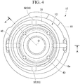
Fig. 4 is an enlarged sectional view of main portions of the Oldham's ring according to the embodiment of the present invention. -
Fig. 5 is a sectional view along line A-A ofFig. 4 . -
Fig. 6 is an enlarged sectional view of main portions illustrating a modification of the Oldham's ring according to the embodiment of the present invention. - Hereinafter, a
scroll compressor 1 according to an embodiment of the present invention will be described. - As illustrated in
Fig. 1 , thescroll compressor 1 includes amain shaft 2 that rotates about an axis O, ahousing 3 that supports themain shaft 2 to be rotatable relative to themain shaft 2, anorbiting scroll 10 and afixed scroll 11 that are provided in thehousing 3, and an Oldham'sring 12 that supports theorbiting scroll 10. - The
main shaft 2 has a columnar shape whose center is the axis O, and rotates about the axis O. Further, an eccentric bushing 14 having a tubular shape whose center is a central axis O1 eccentric from the axis O is fixed to an upper end of themain shaft 2. - The
housing 3 has a housingmain body 16 that has a tubular shape in which a space S is formed, and abearing 17 that is fixed to an inner surface of the housingmain body 16 in the space S. Thehousing 3 supports themain shaft 2 via thebearing 17, and themain shaft 2 is housed in the space S. - The
bearing 17 has a bearingmain body portion 18 that surrounds themain shaft 2 from the outside in a radial direction and supports themain shaft 2 to be rotatable relative to thehousing 3, and anannular protrusion portion 19 that extends toward an upper side, which becomes one side in a direction of the axis O, along an inner surface of the housingmain body 16 from an outer position of the bearingmain body portion 18 in a radial direction and has an annular shape fixed to the inner surface of the housingmain body 16. An eccentric bushing 14 is disposed inside theannular protrusion portion 19. Furthermore, as illustrated inFig. 4 or5 , a disk-like thrust plate 18a whose center is the axis O is mounted on an upper surface of the bearingmain body portion 18. - Furthermore, an
introduction port 4 and adischarge port 5, which allow communication between the space S and an exterior of thehousing 3 and to which a refrigerant F can flow, are formed in thehousing 3. - The
orbiting scroll 10 is mounted on themain shaft 2 via the eccentric bushing 14 from above. The orbitingscroll 10 is made rotatable about the central axis O1 of the eccentric bushing 14 relative to the eccentric bushing 14. - Further, although detailed illustration is omitted, the
orbiting scroll 10 has anend plate 21 that has a disk shape, alap wall 22 that has a spiral shape when viewed in an extending direction of the central axis O1, is provided integrally with theend plate 21, and extends from theend plate 21 to an upper side that is one side of the central axis O1, and atubular portion 23 that extends downward from theend plate 21 and is mounted on the eccentric bushing 14 on the same axis as the central axis O1 to cover the eccentric bushing 14 from outside. Themain shaft 2 is rotated, and thereby the orbiting scroll 10 moves around the axis O of themain shaft 2. - Although detailed illustration is omitted, the
fixed scroll 11 has an end plate 27 that is integrally formed at theannular protrusion portion 19 of thebearing 17, and has a disk shape like theorbiting scroll 10, and alap wall 28 that has a spiral shape when viewed in an extending direction of the central axis O1, is provided integrally with the end plate 27, and extends from the end plate 27 to a lower side that is one side of the central axis O1 toward theend plate 21 of theorbiting scroll 10. - The end plate 27 of the
fixed scroll 11 and theend plate 21 of theorbiting scroll 10 are disposed vertically apart from each other in an extending direction of the central axis O1, and thelap wall 28 of thefixed scroll 11 and thelap wall 22 of theorbiting scroll 10 are be engaged with each other, and face each other in a radial direction of the central axis O1. A compression chamber C is formed between thelap walls - The refrigerant F is introduced into the compression chamber C through the
introduction port 4 of thehousing 3. A shape of the compression chamber C changes as the orbiting scroll 10 revolves around the axis O, and thereby the introduced refrigerant F is compressed, and is then discharged from thedischarge port 5 to the exterior of thehousing 3. - Next, the Oldham's
ring 12 will be described. - As illustrated in
Fig. 2 , the Oldham'sring 12 is disposed below theend plate 21 of the orbitingscroll 10. The Oldham'sring 12 is supported from below by theannular protrusion portion 19, and curbs rotation of the orbitingscroll 10. - To be more specific, the Oldham's
ring 12 includes amain body portion 31 that has a toric shape disposed to surround the axis O and the central axis O1, and a plurality ofkeys 32 that protrude from front and back surfaces of themain body portion 31. - Here, the front surface of the
main body portion 31 is an upper surface that is a surface directed upward, and the back surface is a lower surface that is a surface directed downward. The keys may protrude outward from an outer circumferential surface of themain body portion 31 in a radial direction. - The
main body portion 31 is provided to be interposed between theend plate 21 of the orbitingscroll 10 and theannular protrusion portion 19. - As the
keys 32, two types ofkeys 32 that arefirst keys 33 that protrude upward from the front surface of themain body portion 31 andsecond keys 35 that protrude downward from the back surface of themain body portion 31 are provided. Inner circumferential surfaces of thefirst keys 33 and an inner circumferential surface of themain body portion 31 are flush with each other. - A pair of the
first keys 33 are integrally formed on themain body portion 31 at positions 180 degrees from each other in a circumferential direction of themain body portion 31. Here, as illustrated inFig. 3A ,first groove portions 38 that are recessed upward are formed in a lower surface of theend plate 21 of the orbitingscroll 10 which faces the Oldham'sring 12. Thefirst keys 33 are fitted into thefirst groove portions 38. That is, a pair of thefirst groove portions 38 are formed at positions corresponding to the positions at which thefirst keys 33 are formed. - The
first keys 33 linearly reciprocate relative to thefirst groove portions 38 in an extending direction of a line segment L1 (seeFig. 2 ) that links the pair offirst keys 33. That is, thefirst keys 33 have first slidingsurfaces 33a, as surfaces that face one side of themain body portion 31 in a circumferential direction, which linearly reciprocate in contact withinner surfaces 38a of thefirst groove portions 38. - Like the
first keys 33, a pair of thesecond keys 35 are integrally formed on themain body portion 31 at positions 180 degrees from each other in a circumferential direction of themain body portion 31. Thesecond keys 35 are provided at positions 90 degrees from thefirst keys 33 in a circumferential direction. Here, as illustrated inFig. 3B ,second groove portions 39 that are recessed downward are formed in an upper surface of theannular protrusion portion 19 which faces the Oldham'sring 12. Thesecond keys 35 are fitted into thesecond groove portions 39. That is, a pair of thesecond groove portions 39 are formed at positions corresponding to the positions at which thesecond keys 35 are formed. - The
second keys 35 linearly reciprocate relative to thesecond groove portions 39 in an extending direction of a line segment L2 (seeFig. 2 ) that links the pair ofsecond keys 35. That is, thesecond keys 35 has second slidingsurfaces 35a, as surfaces that face one side of themain body portion 31 in a circumferential direction, which linearly reciprocate in contact withinner surfaces 39a of thesecond groove portions 39. Here, a sliding direction D2 of the second key 35 is a direction perpendicular to a sliding direction D1 of thefirst key 33. Themain body portion 31 reciprocates in the sliding direction D2. - As illustrated in
Fig. 4 or5 ,flange portions 40 are formed on the inner circumferential surface of the main body portion 31 (i.e., a surface that faces an inner side in a radial direction of the axis O). Theflange portions 40 protrude inward from the inner circumferential surface of themain body portion 31 in a radial direction. Theflange portions 40 have plate shapes that spread in a plane perpendicular to the axis O. Edges on inner circumferential sides of theflange portions 40 have circular arc shapes whose centers are the axis O. Inner circumferential surfaces of theflange portions 40 are flush with inner circumferential surfaces of thesecond keys 35. - As illustrated in
Fig. 5 , when a dimension of themain body portion 31 in the direction of the axis O is defined as t0, and a dimension of theflange portion 40 in the direction of the axis O is defined as t1, a relationship of Math (1) shown below is established.
- Furthermore, when a dimension from the inner circumferential surface to an outer circumferential surface of the
main body portion 31 is defined as w0, and a dimension from the inner circumferential surface of theflange portion 40 to the outer circumferential surface of themain body portion 31 is defined as w1, a relationship of Math (2) shown below is established.
- Of surfaces of each
flange portion 40 which face both sides in the direction of the axis O, a surface facing a lower side is flush with a lower surface of themain body portion 31 which is located on a lower side of themain body portion 31. That is, theflange portions 40 are eccentrically formed on the lower side of themain body portion 31. Theflange portions 40 are not provided at the circumferential positions at which thefirst keys 33 are provided in a circumferential direction of the main body portion 31 (in a circumferential direction of the axis O). In other words, theflange portions 40 are provided only in regions that include the positions corresponding to thesecond keys 35 within the inner circumferential surface of themain body portion 31. In the present embodiment, a pair offlange portions 40 are formed in regions including the circumferential positions at which thesecond keys 35 are provided and regions excluding the circumferential positions at which thefirst keys 33 are provided to continuously extend in a circumferential direction. - Here, as illustrated in
Fig. 5 , a counterbored portion R, which is recessed inward in the radial direction of the axis O, is formed at a connection portion between the bearingmain body portion 18 and thethrust plate 18a in thebearing 17. The counterbored portion R is formed across both the bearingmain body portion 18 and thethrust plate 18a. - A dimension of the counterbored portion R in the direction of the axis O is set to be approximately the same as or slightly larger than the dimension (t1 mentioned above) of the
flange portion 40 in the direction of the axis O. Thus, while the Oldham'sring 12 slides, theflange portions 40 are allowed to enter (be housed in) the counterbored portion R without interfering with the bearingmain body portion 18 and thethrust plate 18a. That is, theflange portions 40 overlap the bearing 17 that is another facing member when theflange portions 40 are viewed in the direction of the axis O. - In the Oldham's
ring 12, theflange portions 40 are formed on themain body portion 31. Thus, without increasing dimensions of the entire Oldham'sring 12, strength of themain body portion 31 can be enhanced. Furthermore, since theflange portions 40 are configured to be allowed to overlap with another facing member (the bearing 17) when theflange portions 40 are viewed in the direction of the axis O, interference between the other member and the Oldham'sring 12 can be avoided. Furthermore, according to the constitution, since theflange portions 40 have simple plate shapes, design and production can be easily performed compared to a case where another shape is adopted. - An embodiment of the present invention has been described with reference to
Figs. 1 to 5 . The constitution is one example, and various alternations or modifications can be performed on this constitution. For example, in the embodiment, an example of thebearing 17 has been described as an example of the other member facing the Oldham'sring 12. However, the Oldham'sring 12 does not necessarily face thebearing 17 in the direction of the axis O, and may be disposed to face a member other than thebearing 17. The other member facing the Oldham'sring 12 may be a member formed integrally with the housingmain body 16, and may be a member separated from the housingmain body 16 and mounted on the housingmain body 16. - Furthermore, in the embodiment, the constitution in which the
flange portions 40 are provided only on at least a part of the inner circumferential surface of themain body portion 31 has been described as an example. However, the constitution of theflange portions 40 is not limited thereto, and theflange portions 40 may be provided throughout the inner circumferential surface of themain body portion 31. That is, theflange portions 40 may be at least provided to protrude from themain body portion 31 in the extending direction of the line segment L2 which is the direction in which the Oldham'sring 12 slides in a reciprocating way. - In addition, as the shapes of the
flange portions 40, a constitution other than that in the embodiment can be adopted. For example, as illustrated inFig. 6 , of both surfaces of theflange portions 40, a surface directed upward is inclined, and may thereby form aninclined surface 40a. In a sectional view including the axis O, theinclined surface 40a spreads in an inclined direction with respect to the axis O. To be specific, theinclined surface 40a spreads from bottom to top as it is goes from inside to outside in the radial direction of the axis O. - Further, the counterbored portion R having a shape corresponding to the
inclined surface 40a is formed at thethrust plate 18a. An outer circumferential surface of the counterbored portion R is approximately parallel to theinclined surface 40a, and spreads in an inclined direction with respect to the axis O in the sectional view including the axis O. According to the constitution, in comparison with the case where theflange portions 40 have the plate shapes, a thickness of the flange portions 40 (a dimension in the direction of the axis O) can be secured. Thus, the strength of the Oldham'sring 12 can be further enhanced. - The Oldham's ring and the scroll compressor can be made small with high strength.
-
- 1:
- Scroll compressor
- 2:
- Main shaft
- 3:
- Housing
- 4:
- Introduction port
- 5:
- Discharge port
- 10:
- Orbiting scroll
- 11:
- Fixed scroll
- 12:
- Oldham's ring
- 14:
- Eccentric bushing
- 16:
- Housing main body
- 17:
- Bearing
- 18:
- Bearing main body portion
- 18a:
- Thrust plate
- 19:
- Annular protrusion portion
- 21:
- End plate
- 22:
- Lap wall
- 23:
- Tubular portion
- 27:
- End plate
- 28:
- Lap wall
- 31:
- Main body portion
- 32:
- Key
- 33:
- First key
- 33a:
- First sliding surface
- 35:
- Second key
- 35a:
- Second sliding surface
- 38:
- First groove portion
- 38a:
- Inner surface
- 39:
- Second groove portion
- 39a:
- Inner surface
- 40:
- Flange portion
- 40a:
- Inclined surface
- O:
- Axis
- O1:
- Central axis
- R:
- Counterbored portion
- F:
- Refrigerant
- S:
- Space
- C:
- Compression chamber
- L1, L2:
- Line segment
Claims (5)
- An Oldham's ring installed on a scroll compressor including an orbiting scroll and a fixed scroll, wherein the orbiting scroll is fixed on a main shaft rotatably supported by a housing, a compression chamber in which a refrigerant is compressed are formed between the orbiting scroll and the fixed scroll facing the orbiting scroll, and the orbiting scroll is supported by the Oldham's ring to revolve around an axis of the main shaft without rotation, the Oldham's ring comprising:a main body portion having an annular shape and is disposed to surround the axis;a plurality of keys protruding from the main body portion, fitted into groove portions formed in the orbiting scroll and the housing, and configured to reciprocatingly slide with respect to inner surfaces of the groove portions to allow the main body portion to linearly reciprocate; andflange portions formed on the main body portion so as to protrude radially inward from an inner circumferential surface of the main body portion in a direction in which the main body portion slides in a reciprocating way,wherein the flange portions is allowed to overlap with another facing member when the flange portions are viewed in a direction of the axis.
- The Oldham's ring according to claim 1, wherein the flange portions have plate shapes that spread in a direction perpendicular to the axis.
- The Oldham's ring according to claim 1, wherein the flange portions have inclined surfaces that spread in an inclined direction with respect to the axis.
- The Oldham's ring according to any one of claims 1 to 3, wherein the other facing member is a bearing, and a counterbored portion in which the flange portions are housed is formed in the bearing.
- A scroll compressor comprising:a main shaft configured to rotate about an axis;a housing configured to support the main shaft to be rotatable relative to the main shaft;an orbiting scroll formed on the main shaft;a fixed scroll configured to face the orbiting scroll and to form a compression chamber compressing a refrigerant between the orbiting scroll and the fixed scroll; andthe Oldham's ring described in any one of claims 1 to 4 configured to support the orbiting scroll.
Applications Claiming Priority (2)
| Application Number | Priority Date | Filing Date | Title |
|---|---|---|---|
| JP2017150056A JP7014544B2 (en) | 2017-08-02 | 2017-08-02 | Oldam ring, scroll compressor |
| PCT/JP2018/021216 WO2019026410A1 (en) | 2017-08-02 | 2018-06-01 | Oldham's ring and scroll compressor |
Publications (4)
| Publication Number | Publication Date |
|---|---|
| EP3660312A1 true EP3660312A1 (en) | 2020-06-03 |
| EP3660312A4 EP3660312A4 (en) | 2020-08-05 |
| EP3660312C0 EP3660312C0 (en) | 2024-09-18 |
| EP3660312B1 EP3660312B1 (en) | 2024-09-18 |
Family
ID=65233670
Family Applications (1)
| Application Number | Title | Priority Date | Filing Date |
|---|---|---|---|
| EP18841872.7A Active EP3660312B1 (en) | 2017-08-02 | 2018-06-01 | Scroll compressor with oldham ring |
Country Status (5)
| Country | Link |
|---|---|
| EP (1) | EP3660312B1 (en) |
| JP (1) | JP7014544B2 (en) |
| CN (1) | CN111133196B (en) |
| AU (1) | AU2018310263B2 (en) |
| WO (1) | WO2019026410A1 (en) |
Families Citing this family (3)
| Publication number | Priority date | Publication date | Assignee | Title |
|---|---|---|---|---|
| EP3936723B1 (en) * | 2019-04-11 | 2024-10-09 | Mitsubishi Heavy Industries Thermal Systems, Ltd. | Scroll compressor |
| CN209875464U (en) * | 2019-05-10 | 2019-12-31 | 艾默生环境优化技术(苏州)有限公司 | Scroll compressor having a plurality of scroll members |
| CN114688019A (en) * | 2022-02-18 | 2022-07-01 | 松下压缩机(大连)有限公司 | Compressor supporting structure |
Family Cites Families (10)
| Publication number | Priority date | Publication date | Assignee | Title |
|---|---|---|---|---|
| JP2543031B2 (en) * | 1986-02-03 | 1996-10-16 | 松下電器産業株式会社 | Scroll compressor |
| CN201050479Y (en) * | 2007-03-27 | 2008-04-23 | 珠海格力电器股份有限公司 | Anti-rotation mechanism of scroll compressor |
| JP2014029117A (en) * | 2012-07-31 | 2014-02-13 | Hitachi Appliances Inc | Scroll compressor |
| JP6396090B2 (en) * | 2014-06-19 | 2018-09-26 | 日立ジョンソンコントロールズ空調株式会社 | Oldham ring and scroll compressor |
| JP6485623B2 (en) | 2014-10-20 | 2019-03-20 | 三菱重工サーマルシステムズ株式会社 | Scroll compressor |
| US9638036B2 (en) * | 2014-10-31 | 2017-05-02 | Emerson Climate Technologies, Inc. | Scroll compressor including oldham coupling having keys that are slidingly received in slots of a non-orbiting scroll and/or an orbiting scroll |
| JP6098706B1 (en) * | 2015-12-28 | 2017-03-22 | ダイキン工業株式会社 | Scroll compressor |
| JP6697902B2 (en) | 2016-02-26 | 2020-05-27 | 株式会社三井ハイテック | Tray and heat treatment method |
| EP3447294B1 (en) * | 2016-04-18 | 2021-02-17 | Daikin Industries, Ltd. | Scroll compressor |
| CN106014981B (en) * | 2016-07-28 | 2018-01-05 | 陆亚明 | Scroll type air compressor assembly |
-
2017
- 2017-08-02 JP JP2017150056A patent/JP7014544B2/en active Active
-
2018
- 2018-06-01 WO PCT/JP2018/021216 patent/WO2019026410A1/en not_active Ceased
- 2018-06-01 AU AU2018310263A patent/AU2018310263B2/en active Active
- 2018-06-01 EP EP18841872.7A patent/EP3660312B1/en active Active
- 2018-06-01 CN CN201880062452.9A patent/CN111133196B/en active Active
Also Published As
| Publication number | Publication date |
|---|---|
| CN111133196B (en) | 2022-03-18 |
| WO2019026410A1 (en) | 2019-02-07 |
| AU2018310263B2 (en) | 2021-09-23 |
| EP3660312C0 (en) | 2024-09-18 |
| JP7014544B2 (en) | 2022-02-01 |
| JP2019027406A (en) | 2019-02-21 |
| EP3660312B1 (en) | 2024-09-18 |
| AU2018310263A1 (en) | 2020-03-19 |
| CN111133196A (en) | 2020-05-08 |
| EP3660312A4 (en) | 2020-08-05 |
Similar Documents
| Publication | Publication Date | Title |
|---|---|---|
| EP2993352B1 (en) | Scroll compressor | |
| US9366253B2 (en) | Scroll compressor and processing method of scroll including a projection on a tip seal and a hole in a tip seal groove | |
| EP3754199B1 (en) | Scroll compressor | |
| EP3660312B1 (en) | Scroll compressor with oldham ring | |
| EP3214263B1 (en) | Two-cylinder hermetic compressor | |
| US9638036B2 (en) | Scroll compressor including oldham coupling having keys that are slidingly received in slots of a non-orbiting scroll and/or an orbiting scroll | |
| US9523361B2 (en) | Scroll compressor having back pressure chamber that operatively contains a discharge pressure and an intermediate pressure during different periods of time within a single compression cycle | |
| JP7595605B2 (en) | Compressor | |
| US8092199B2 (en) | Scroll compressor including a plurality of shoulder sections | |
| US8734142B2 (en) | Rotation preventing member of a scroll compressor | |
| CN105339665A (en) | Scroll-type fluid machine and gasket therefor | |
| EP2669523B1 (en) | Scroll compressor | |
| US10920775B2 (en) | Scroll compressor with different sized gaps formed between inner and outer peripheral surfaces of scroll laps | |
| US6193489B1 (en) | Shaft assembly mechanism for scroll compressor | |
| KR101454251B1 (en) | Scroll compressor with fixed scroll supporting means | |
| EP3936723B1 (en) | Scroll compressor | |
| EP3647596B1 (en) | Rotary compressor | |
| US20210108637A1 (en) | Scroll compressor | |
| EP4621235A1 (en) | Thrust support mechanism | |
| JP2018009544A (en) | Scroll Type Fluid Machine | |
| US20170350393A1 (en) | Cylinder rotary compressor | |
| JP2020153328A (en) | Internal gear pump | |
| JP2008240709A (en) | Compressor | |
| KR20140011770A (en) | Cam structure of air compressure |
Legal Events
| Date | Code | Title | Description |
|---|---|---|---|
| STAA | Information on the status of an ep patent application or granted ep patent |
Free format text: STATUS: THE INTERNATIONAL PUBLICATION HAS BEEN MADE |
|
| PUAI | Public reference made under article 153(3) epc to a published international application that has entered the european phase |
Free format text: ORIGINAL CODE: 0009012 |
|
| STAA | Information on the status of an ep patent application or granted ep patent |
Free format text: STATUS: REQUEST FOR EXAMINATION WAS MADE |
|
| 17P | Request for examination filed |
Effective date: 20200226 |
|
| AK | Designated contracting states |
Kind code of ref document: A1 Designated state(s): AL AT BE BG CH CY CZ DE DK EE ES FI FR GB GR HR HU IE IS IT LI LT LU LV MC MK MT NL NO PL PT RO RS SE SI SK SM TR |
|
| AX | Request for extension of the european patent |
Extension state: BA ME |
|
| A4 | Supplementary search report drawn up and despatched |
Effective date: 20200708 |
|
| RIC1 | Information provided on ipc code assigned before grant |
Ipc: F04C 18/02 20060101AFI20200702BHEP Ipc: F01C 17/06 20060101ALI20200702BHEP Ipc: F01C 21/02 20060101ALI20200702BHEP Ipc: F01C 1/02 20060101ALI20200702BHEP |
|
| DAV | Request for validation of the european patent (deleted) | ||
| DAX | Request for extension of the european patent (deleted) | ||
| STAA | Information on the status of an ep patent application or granted ep patent |
Free format text: STATUS: EXAMINATION IS IN PROGRESS |
|
| 17Q | First examination report despatched |
Effective date: 20220816 |
|
| GRAP | Despatch of communication of intention to grant a patent |
Free format text: ORIGINAL CODE: EPIDOSNIGR1 |
|
| STAA | Information on the status of an ep patent application or granted ep patent |
Free format text: STATUS: GRANT OF PATENT IS INTENDED |
|
| INTG | Intention to grant announced |
Effective date: 20240418 |
|
| RAP3 | Party data changed (applicant data changed or rights of an application transferred) |
Owner name: MITSUBISHI HEAVY INDUSTRIES THERMAL SYSTEMS, LTD. |
|
| GRAS | Grant fee paid |
Free format text: ORIGINAL CODE: EPIDOSNIGR3 |
|
| GRAA | (expected) grant |
Free format text: ORIGINAL CODE: 0009210 |
|
| STAA | Information on the status of an ep patent application or granted ep patent |
Free format text: STATUS: THE PATENT HAS BEEN GRANTED |
|
| AK | Designated contracting states |
Kind code of ref document: B1 Designated state(s): AL AT BE BG CH CY CZ DE DK EE ES FI FR GB GR HR HU IE IS IT LI LT LU LV MC MK MT NL NO PL PT RO RS SE SI SK SM TR |
|
| REG | Reference to a national code |
Ref country code: GB Ref legal event code: FG4D |
|
| REG | Reference to a national code |
Ref country code: CH Ref legal event code: EP |
|
| REG | Reference to a national code |
Ref country code: IE Ref legal event code: FG4D |
|
| REG | Reference to a national code |
Ref country code: DE Ref legal event code: R096 Ref document number: 602018074579 Country of ref document: DE |
|
| U01 | Request for unitary effect filed |
Effective date: 20241007 |
|
| U07 | Unitary effect registered |
Designated state(s): AT BE BG DE DK EE FI FR IT LT LU LV MT NL PT RO SE SI Effective date: 20241028 |
|
| PG25 | Lapsed in a contracting state [announced via postgrant information from national office to epo] |
Ref country code: NO Free format text: LAPSE BECAUSE OF FAILURE TO SUBMIT A TRANSLATION OF THE DESCRIPTION OR TO PAY THE FEE WITHIN THE PRESCRIBED TIME-LIMIT Effective date: 20241218 |
|
| PG25 | Lapsed in a contracting state [announced via postgrant information from national office to epo] |
Ref country code: GR Free format text: LAPSE BECAUSE OF FAILURE TO SUBMIT A TRANSLATION OF THE DESCRIPTION OR TO PAY THE FEE WITHIN THE PRESCRIBED TIME-LIMIT Effective date: 20241219 |
|
| PG25 | Lapsed in a contracting state [announced via postgrant information from national office to epo] |
Ref country code: HR Free format text: LAPSE BECAUSE OF FAILURE TO SUBMIT A TRANSLATION OF THE DESCRIPTION OR TO PAY THE FEE WITHIN THE PRESCRIBED TIME-LIMIT Effective date: 20240918 |
|
| PG25 | Lapsed in a contracting state [announced via postgrant information from national office to epo] |
Ref country code: RS Free format text: LAPSE BECAUSE OF FAILURE TO SUBMIT A TRANSLATION OF THE DESCRIPTION OR TO PAY THE FEE WITHIN THE PRESCRIBED TIME-LIMIT Effective date: 20241218 |
|
| PG25 | Lapsed in a contracting state [announced via postgrant information from national office to epo] |
Ref country code: RS Free format text: LAPSE BECAUSE OF FAILURE TO SUBMIT A TRANSLATION OF THE DESCRIPTION OR TO PAY THE FEE WITHIN THE PRESCRIBED TIME-LIMIT Effective date: 20241218 Ref country code: NO Free format text: LAPSE BECAUSE OF FAILURE TO SUBMIT A TRANSLATION OF THE DESCRIPTION OR TO PAY THE FEE WITHIN THE PRESCRIBED TIME-LIMIT Effective date: 20241218 Ref country code: HR Free format text: LAPSE BECAUSE OF FAILURE TO SUBMIT A TRANSLATION OF THE DESCRIPTION OR TO PAY THE FEE WITHIN THE PRESCRIBED TIME-LIMIT Effective date: 20240918 Ref country code: GR Free format text: LAPSE BECAUSE OF FAILURE TO SUBMIT A TRANSLATION OF THE DESCRIPTION OR TO PAY THE FEE WITHIN THE PRESCRIBED TIME-LIMIT Effective date: 20241219 |
|
| PG25 | Lapsed in a contracting state [announced via postgrant information from national office to epo] |
Ref country code: IS Free format text: LAPSE BECAUSE OF FAILURE TO SUBMIT A TRANSLATION OF THE DESCRIPTION OR TO PAY THE FEE WITHIN THE PRESCRIBED TIME-LIMIT Effective date: 20250118 |
|
| PG25 | Lapsed in a contracting state [announced via postgrant information from national office to epo] |
Ref country code: SM Free format text: LAPSE BECAUSE OF FAILURE TO SUBMIT A TRANSLATION OF THE DESCRIPTION OR TO PAY THE FEE WITHIN THE PRESCRIBED TIME-LIMIT Effective date: 20240918 |
|
| PG25 | Lapsed in a contracting state [announced via postgrant information from national office to epo] |
Ref country code: ES Free format text: LAPSE BECAUSE OF FAILURE TO SUBMIT A TRANSLATION OF THE DESCRIPTION OR TO PAY THE FEE WITHIN THE PRESCRIBED TIME-LIMIT Effective date: 20240918 |
|
| PG25 | Lapsed in a contracting state [announced via postgrant information from national office to epo] |
Ref country code: CZ Free format text: LAPSE BECAUSE OF FAILURE TO SUBMIT A TRANSLATION OF THE DESCRIPTION OR TO PAY THE FEE WITHIN THE PRESCRIBED TIME-LIMIT Effective date: 20240918 Ref country code: PL Free format text: LAPSE BECAUSE OF FAILURE TO SUBMIT A TRANSLATION OF THE DESCRIPTION OR TO PAY THE FEE WITHIN THE PRESCRIBED TIME-LIMIT Effective date: 20240918 |
|
| PG25 | Lapsed in a contracting state [announced via postgrant information from national office to epo] |
Ref country code: SK Free format text: LAPSE BECAUSE OF FAILURE TO SUBMIT A TRANSLATION OF THE DESCRIPTION OR TO PAY THE FEE WITHIN THE PRESCRIBED TIME-LIMIT Effective date: 20240918 |
|
| U20 | Renewal fee for the european patent with unitary effect paid |
Year of fee payment: 8 Effective date: 20250509 |
|
| PGFP | Annual fee paid to national office [announced via postgrant information from national office to epo] |
Ref country code: GB Payment date: 20250501 Year of fee payment: 8 |
|
| PLBE | No opposition filed within time limit |
Free format text: ORIGINAL CODE: 0009261 |
|
| STAA | Information on the status of an ep patent application or granted ep patent |
Free format text: STATUS: NO OPPOSITION FILED WITHIN TIME LIMIT |
|
| 26N | No opposition filed |
Effective date: 20250619 |
|
| REG | Reference to a national code |
Ref country code: CH Ref legal event code: H13 Free format text: ST27 STATUS EVENT CODE: U-0-0-H10-H13 (AS PROVIDED BY THE NATIONAL OFFICE) Effective date: 20260127 |
|
| PG25 | Lapsed in a contracting state [announced via postgrant information from national office to epo] |
Ref country code: MC Free format text: LAPSE BECAUSE OF FAILURE TO SUBMIT A TRANSLATION OF THE DESCRIPTION OR TO PAY THE FEE WITHIN THE PRESCRIBED TIME-LIMIT Effective date: 20240918 |
|
| PG25 | Lapsed in a contracting state [announced via postgrant information from national office to epo] |
Ref country code: IE Free format text: LAPSE BECAUSE OF NON-PAYMENT OF DUE FEES Effective date: 20250601 |
|
| PG25 | Lapsed in a contracting state [announced via postgrant information from national office to epo] |
Ref country code: CH Free format text: LAPSE BECAUSE OF NON-PAYMENT OF DUE FEES Effective date: 20250630 |