EP3660262A1 - Seal stem - Google Patents
Seal stem Download PDFInfo
- Publication number
- EP3660262A1 EP3660262A1 EP19219493.4A EP19219493A EP3660262A1 EP 3660262 A1 EP3660262 A1 EP 3660262A1 EP 19219493 A EP19219493 A EP 19219493A EP 3660262 A1 EP3660262 A1 EP 3660262A1
- Authority
- EP
- European Patent Office
- Prior art keywords
- seal
- tubular
- ring
- seal ring
- disposed
- Prior art date
- Legal status (The legal status is an assumption and is not a legal conclusion. Google has not performed a legal analysis and makes no representation as to the accuracy of the status listed.)
- Granted
Links
- 241000283216 Phocidae Species 0.000 title description 116
- 238000007789 sealing Methods 0.000 claims abstract description 31
- 238000001125 extrusion Methods 0.000 claims abstract description 24
- 238000000034 method Methods 0.000 claims description 14
- 238000004140 cleaning Methods 0.000 claims 1
- 210000004907 gland Anatomy 0.000 description 36
- 230000000712 assembly Effects 0.000 description 24
- 238000000429 assembly Methods 0.000 description 24
- 238000003780 insertion Methods 0.000 description 5
- 230000037431 insertion Effects 0.000 description 5
- 239000013536 elastomeric material Substances 0.000 description 4
- 230000004888 barrier function Effects 0.000 description 3
- 230000008901 benefit Effects 0.000 description 2
- 239000000463 material Substances 0.000 description 2
- 229920001343 polytetrafluoroethylene Polymers 0.000 description 2
- 239000004810 polytetrafluoroethylene Substances 0.000 description 2
- 239000004696 Poly ether ether ketone Substances 0.000 description 1
- JUPQTSLXMOCDHR-UHFFFAOYSA-N benzene-1,4-diol;bis(4-fluorophenyl)methanone Chemical compound OC1=CC=C(O)C=C1.C1=CC(F)=CC=C1C(=O)C1=CC=C(F)C=C1 JUPQTSLXMOCDHR-UHFFFAOYSA-N 0.000 description 1
- 230000007423 decrease Effects 0.000 description 1
- 239000003292 glue Substances 0.000 description 1
- 238000004519 manufacturing process Methods 0.000 description 1
- 229920001643 poly(ether ketone) Polymers 0.000 description 1
- 229920002530 polyetherether ketone Polymers 0.000 description 1
- -1 polytetrafluoroethylene Polymers 0.000 description 1
- 230000000717 retained effect Effects 0.000 description 1
- 238000005096 rolling process Methods 0.000 description 1
- 239000003351 stiffener Substances 0.000 description 1
- 239000011800 void material Substances 0.000 description 1
Images


Classifications
-
- E—FIXED CONSTRUCTIONS
- E21—EARTH OR ROCK DRILLING; MINING
- E21B—EARTH OR ROCK DRILLING; OBTAINING OIL, GAS, WATER, SOLUBLE OR MELTABLE MATERIALS OR A SLURRY OF MINERALS FROM WELLS
- E21B17/00—Drilling rods or pipes; Flexible drill strings; Kellies; Drill collars; Sucker rods; Cables; Casings; Tubings
- E21B17/02—Couplings; joints
- E21B17/08—Casing joints
-
- E—FIXED CONSTRUCTIONS
- E21—EARTH OR ROCK DRILLING; MINING
- E21B—EARTH OR ROCK DRILLING; OBTAINING OIL, GAS, WATER, SOLUBLE OR MELTABLE MATERIALS OR A SLURRY OF MINERALS FROM WELLS
- E21B33/00—Sealing or packing boreholes or wells
- E21B33/10—Sealing or packing boreholes or wells in the borehole
- E21B33/12—Packers; Plugs
- E21B33/1208—Packers; Plugs characterised by the construction of the sealing or packing means
-
- E—FIXED CONSTRUCTIONS
- E21—EARTH OR ROCK DRILLING; MINING
- E21B—EARTH OR ROCK DRILLING; OBTAINING OIL, GAS, WATER, SOLUBLE OR MELTABLE MATERIALS OR A SLURRY OF MINERALS FROM WELLS
- E21B43/00—Methods or apparatus for obtaining oil, gas, water, soluble or meltable materials or a slurry of minerals from wells
- E21B43/02—Subsoil filtering
- E21B43/10—Setting of casings, screens, liners or the like in wells
Definitions
- Embodiments of the present invention generally relate to a downhole seal arrangement. More particularly, embodiments of the present invention relate to seal stem arrangment for reconnecting with a tubular.
- FIG. 1 shows a seal stem disposed inside a polish bore receptacle 3 ("PBR") of the liner.
- the seal stem includes a mandrel 10 and three assemblies 11, 12, 13 of Chevron-type seal rings disposed on a reduced diameter portion of the mandrel 10.
- Each assembly 11, 12, 13 includes upper and lower travel stops 14, 16 attached to the mandrel 10.
- Two stacks of oppositely facing Chevron-type seal rings 21, 23 are disposed between the travel stops 14, 16.
- a stack of upwardly oriented seal rings 21 and a stack of downwardly oriented seal rings 22 are disposed on each side of an o-ring 23.
- Each stack may include as many as twenty seal rings 21, 22 to provide adequate sealing with the PBR.
- the Chevron seal rings 21, 22 are oriented in opposite directions to seal against differential pressures in either direction.
- One of the drawbacks of this design is a reduced diameter portion 8 is created to accommodate the seal assemblies 11, 12, 13.
- the reduced diameter portion 8 decreases the burst and collapse integrity of the mandrel 10.
- Another drawback is one or more of the seals may roll off the seal stem during insertion, removal, or circulation.
- the sealing apparatus includes a mandrel having at least two portions; a first portion having a seal ring disposed on an exterior surface and a second portion without a seal ring disposed on an exterior surface.
- the burst and collapse integrity of the first portion is substantially the same as the second portion.
- the seal ring is disposed around the first portion.
- a sealing apparatus for sealing against a tubular in the wellbore includes a mandrel having a gland; a seal ring disposed in the gland for engaging the tubular; and one or more seal bands disposed in the seal ring.
- the tubular comprises a PBR.
- the gland comprises a groove formed in an outer surface of the mandrel.
- a method of connecting to a tubular in a wellbore includes providing a sealing apparatus having a mandrel having at least two portions, wherein the first portion includes a seal ring disposed on an exterior surface and the second portion without a seal ring disposed on an exterior surface, and wherein a burst integrity of the first portion is substantially the same as the second portion.
- the method includes engaging the seal ring to an interior of the tubular and redistributing a portion of the seal ring along a gap between the mandrel and the tubular.
- a method of connecting to a tubular in a wellbore includes providing a sealing apparatus having a mandrel having a gland; a seal ring disposed in the gland for engaging the tubular; and one or more seal bands disposed in the seal ring. The method also includes engaging the seal ring to an interior of the tubular, and redistributing a portion of the seal ring along a gap between the mandrel and the tubular, thereby forming a seal with the tubular.
- the present invention generally relates to a seal assembly for a downhole tool.
- the seal assembly will be described herein in relation to a seal stem for reconnecting to a tubular such as a liner. It is to be understood, however, that the seal assembly may also be used with other downhole tools. Further, the seal assembly may be used in a downhole tool that is disposed within a cased wellbore or within an open-hole wellbore.
- a seal assembly in one embodiment, includes a mandrel having one or more grooves formed on an outer surface.
- An extrusion resistant seal ring is disposed in each of the grooves. The seal ring may be used to form a seal with a tubular in the wellbore.
- Figure 2 illustrates an embodiment of a seal stem 100.
- the seal stem 100 may be a tubular connected to a tubular string (not shown) such as a tubing string. In another embodiment, the seal stem 100 may be integral with the tubular string.
- the seal stem 100 includes a mandrel 110 and one or more seal assemblies.
- the seal stem 100 may be adapted to form a seal with a tubular in the wellbore.
- the seal stem 100 may engage a precise bore tubular such as a polish bore receptacle ("PBR").
- PBR polish bore receptacle
- the precise bore tubular may include a tubular having a bore machined to a smooth finish, to a predetermined diameter, or both.
- the seal stem 100 may include any suitable number of seal assemblies 120 to create a seal between mandrel 110 and the PBR.
- Figure 3 is an enlarged view of an exemplary seal assembly 120.
- the seal assembly 120 includes a seal ring 125 disposed in a gland 130.
- the gland 130 may be a circumferential groove formed in the outer surface of the mandrel 110. Because the wall thickness of the mandrel 110 on each side of the seal ring 125 is retained, as indicated by reference number 108, the burst and/or collapse properties of the mandrel 110 remain substantially the same.
- the seal assemblies 120 may be molded and bonded to the gland 120.
- a bonding material such as glue, fastener, or other attachment means, may optionally be used to attach the seal ring 125 to the gland 130. Bonding the seal ring 125 in the gland 130 is useful to prevent the seal ring 125 from becoming unstable and swab off during movement of the seal stem 100.
- the seal ring 125 may include an elastomeric material such as poly ether ketone ("PEEK”), polytetrafluoroethylene (“PTFE”), and combinations thereof.
- a volume gap (not shown) may be created between the seal ring 125 and a side of the gland 130. The volume gap is configured to substantially prevent distortion of the seal ring 125 as the seal stem 100 is being inserted into the PBR 162.
- the seal ring 125 includes one or more anti-extrusion bands, such as a first seal band 141 (first anti-extrusion band) and a second seal band 142 (second anti-extrusion band). As shown, the seal bands 141, 142 are embedded in the seal ring 125 in an upper corner of each side of the seal ring 125. In one embodiment, the seal bands 141, 142 are disposed on an outer circumference of the seal ring 125. In another embodiment, the seal bands may be a non-elastomeric anti-extrusion band for supporting high pressure. In yet another embodiment, the seal bands 141, 142 are springs, such as toroidal coil springs. The seal bands 141, 142 may be used to limit the extrusion of the seal ring 125 during expansion of the seal assembly 120. The seal bands 141, 142 may also be used to limit the extrusion of applied differential pressure after expansion of the seal assembly 120.
- Figure 4 shows the seal stem 100 engaged with the PBR 162.
- the seal ring 125 changes its configuration and occupies a portion of the gap 145 between the mandrel 110 and the PBR 162.
- the seal ring 125 includes a protrusion for contact with the PBR 162.
- the protrusion may be any suitable shape such as an arcuate shape, a contour, or double protrusion.
- the protrusion has a height above the mandrel 110 that is more than the distance of the gap 145. Engagement with the PBR 162 causes the elastomeric material of the seal ring 125 to redistribute along the gap 145 between mandrel 110 and the PBR 162.
- the seal bands 141, 142 are springs, such as toroidal coil springs, which expand radially outward into the gap 145 due to the redistribution of the elastomeric material. As the springs expand radially outward, the coils of spring act as a barrier to the flow of the elastomeric material of the seal ring 125. In this manner, the seal bands 141, 142 in the seal ring 125 act as an anti-extrusion barriers.
- Embodiments of the seal assemblies 120 described herein provide several advantages over the prior art. For example, by preventing extrusion of the seal ring 125, the seal bands 141, 142 retain the seal ring 125 in an energized state to create a high-pressure seal between the seal assembly 120 and the PBR 162.
- the seal assembly 120 may create a high-pressure seal in the range of 12,000 to 14,000 psi.
- Another potential benefit is the seal assembly 120 does not require the mandrel 110 to include a reduced diameter portion to accommodate the seal assembly. As a result, the mandrel 110 has a higher burst and collapse property.
- Figure 5 illustrates an embodiment of a seal stem 200.
- the seal stem 200 includes the mandrel 110 and the seal assemblies 120.
- Each seal assembly 120 may include the first seal band 141 (first anti-extrusion band) and the second seal band 142 (second anti-extrusion band) as described herein.
- the seal stem 200 includes a wiper ring 250 disposed adjacent each end of the seal assemblies 120.
- the wiper ring 250 is configured to wipe (or clean) an inner surface 165 of the PBR 162 as the wiper ring 250 contacts and slides along the inner surface 165 when the seal stem 200 is inserted into the PBR 162.
- An optional o-ring 245 may be placed under the wiper ring 250.
- the o-ring 245 is configured to act as a stiffener under the wiper ring 250. In other words, the o-ring 245 stiffens the wiper ring 250 by supporting a portion of the wiper ring 250.
- the wiper ring 250 is disposed in a gland 220.
- the gland 250 may be a circumferential groove formed in the outer surface of the mandrel 110.
- the gland 250 is shaped so as to provide support to the wiper ring 250 as the wiper ring 250 cleans the inner surface 165 of the PBR 162.
- a volume gap 220 is created between the seal ring 125 and a side of the gland 130.
- the volume gap 220 is used to substantially prevent distortion of the seal ring 125 as the seal stem 200 is being inserted into the PBR 162.
- the volume gap 220 is a free-space (empty space, clearance or void) between a portion of the seal ring 125 and a portion of the gland 130 prior to the insertion of the seal stem 200 into the PBR 162.
- the volume gap 220 is created by positioning the seal ring 125 within the gland 130 such that the seal ring 125 is spaced apart from at least one side of the gland 130.
- volume gap 220 in Figure 6 is created by having a side of the gland 130 arranged parallel to the a side of the seal ring 125, the volume gap 220 may be created in any configuration, such as positioned at an angle, without departing from principles of the present invention. Additionally, the size of the volume gap 220 may vary depending on the configuration of the gland 130. In one embodiment, the gland 130 has 3-5% more volume due to the volume gap 220 than a standard gland without a volume gap.
- the seal ring 125 moves into contact with the inner surface 165 of the PBR 162 to create a seal between the seal stem 200 and the PBR 162.
- the seal ring 125 changes configuration and occupies a portion of the volume gap 220.
- the volume gap 220 is located on the side of the seal assembly 120 which is the first portion to be in contact with the inner surface 165 of the PBR 162. The location of the volume gap 220 in the seal assembly 120 allows the seal ring 125 to change position (or reconfigure) within the gland 130 during the insertion operation. Additionally, the volume of the volume gap 220 may change during the insertion operation.
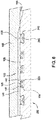
- Figure 7 illustrates an embodiment of a seal stem 300.
- the seal stem 300 includes multiple sets of seal assemblies 120 on the mandrel 110. Each set includes two seal assemblies 120. It should be understood, however, that each set may include any number of seal assemblies, without departing from principles of the present invention.
- Figure 8 illustrates an enlarged partial view of the seal stem 300 of Figure 7 .
- the seal ring 125 includes one or more anti-extrusion bands, such as the first seal band 141 (first anti-extrusion band) and the second seal band 142 (second anti-extrusion band).
- the seal bands 141, 142 are embedded in the seal ring 125 in an upper corner of each side of the seal ring 125.
- the seal ring 125 is disposed in the gland 130.
- the volume gap 220 may be created between the seal ring 125 and the side of the gland 130. The volume gap is configured to substantially prevent distortion of the seal ring 125 as the seal stem 300 is being inserted into the PBR (not shown).
- the mandrel 110 has a first outer diameter 325 between each set of seal assemblies 120 and a second outer diameter 310 at the seal assemblies 120.
- the first outer diameter 325 is smaller than the second outer diameter 310.
- the mandrel 110 has a greater wall thickness (see reference number 310) at the seal assemblies 120 as compared to the wall thickness (see reference number 325) between each set of seal assemblies 120.
- the increased wall thickness at the seal assemblies 120 provides support to the seal assemblies 120 as the seal stem 300 is being inserted into the PBR (not shown). Further, the increased wall thickness at the seal assemblies 120 minimizes the gap (reference number 145 on Figure 4 ) between the mandrel 110 and the PBR.
- the smaller gap may be used to limit the extrusion of the seal ring 125 as the seal stem 300 is being inserted into the PBR.
- the smaller gap may also be used to limit the extrusion of the seal ring 125 when the seal assemblies 120 are subjected to high differential pressure after the seal stem 300 has been inserted into the PBR.
- the seal assemblies 120 will be able to withstand a higher differential pressure above and/or below the seal assemblies 120 with the smaller gap, as described herein, as compared to seal assemblies that do not have the smaller gap.
- the smaller diameter 325 between each set of seal assemblies 120 increases the clearance between the seal stem 300 and the PBR along a substantial portion of the seal stem 300. The increased clearance between the seal stem 300 and the PBR minimizes the risk of the seal stem 300 of becoming stuck (or jammed) when the seal stem 300 is being inserted into the PBR.
- the sealing apparatus includes a mandrel having at least two portions, a first portion having a seal ring disposed on an exterior surface and a second portion without a seal ring disposed on an exterior surface.
- the seal ring is disposed around the first portion.
- the burst and collapse integrity of the first portion is substantially the same as the second portion.
- a sealing apparatus for sealing against a tubular in the wellbore includes a mandrel having a gland; a seal ring disposed in the gland for engaging the tubular, wherein a wall thickness of the mandrel on each side of the gland is substantially the same; and one or more seal band disposed in the seal ring.
- the tubular comprises a PBR.
- the gland comprises a groove formed in an outer surface of the mandrel.
- the mandrel includes two glands, and a wall thickness of the mandrel at one of the glands is less than a wall thickness between the two glands.
Landscapes
- Engineering & Computer Science (AREA)
- Geology (AREA)
- Life Sciences & Earth Sciences (AREA)
- Mining & Mineral Resources (AREA)
- Environmental & Geological Engineering (AREA)
- Fluid Mechanics (AREA)
- Physics & Mathematics (AREA)
- General Life Sciences & Earth Sciences (AREA)
- Geochemistry & Mineralogy (AREA)
- Mechanical Engineering (AREA)
- Gasket Seals (AREA)
- Mechanical Sealing (AREA)
- Joints With Sleeves (AREA)
Abstract
Description
- Embodiments of the present invention generally relate to a downhole seal arrangement. More particularly, embodiments of the present invention relate to seal stem arrangment for reconnecting with a tubular.
- During the life of a well, an operator may decide to reconnect to a liner. One method is to insert a tie back string having a seal stem at a lower end for establishing pressure integrity with a liner.
Figure 1 shows a seal stem disposed inside a polish bore receptacle 3 ("PBR") of the liner. The seal stem includes amandrel 10 and threeassemblies mandrel 10. Eachassembly lower travel stops mandrel 10. Two stacks of oppositely facing Chevron-type seal rings travel stops seal rings 21 and a stack of downwardly orientedseal rings 22 are disposed on each side of an o-ring 23. Each stack may include as many as twentyseal rings seal rings - One of the drawbacks of this design is a reduced
diameter portion 8 is created to accommodate theseal assemblies diameter portion 8 decreases the burst and collapse integrity of themandrel 10. Another drawback is one or more of the seals may roll off the seal stem during insertion, removal, or circulation. - There is a need, therefore, for a seal arrangement that does not require a compromise of the integrity of the seal stem. There is also a need for a seal stem for reconnecting with a tubular without concerns of the seal rolling off the seal stem.
- In one embodiment, the sealing apparatus includes a mandrel having at least two portions; a first portion having a seal ring disposed on an exterior surface and a second portion without a seal ring disposed on an exterior surface. In one embodiment, the burst and collapse integrity of the first portion is substantially the same as the second portion. In another embodiment, the seal ring is disposed around the first portion.
- In one embodiment, a sealing apparatus for sealing against a tubular in the wellbore includes a mandrel having a gland; a seal ring disposed in the gland for engaging the tubular; and one or more seal bands disposed in the seal ring. In another embodiment, the tubular comprises a PBR. In yet another embodiment, the gland comprises a groove formed in an outer surface of the mandrel.
- In another embodiment, a method of connecting to a tubular in a wellbore includes providing a sealing apparatus having a mandrel having at least two portions, wherein the first portion includes a seal ring disposed on an exterior surface and the second portion without a seal ring disposed on an exterior surface, and wherein a burst integrity of the first portion is substantially the same as the second portion. In one embodiment, the method includes engaging the seal ring to an interior of the tubular and redistributing a portion of the seal ring along a gap between the mandrel and the tubular.
- In another embodiment, a method of connecting to a tubular in a wellbore includes providing a sealing apparatus having a mandrel having a gland; a seal ring disposed in the gland for engaging the tubular; and one or more seal bands disposed in the seal ring. The method also includes engaging the seal ring to an interior of the tubular, and redistributing a portion of the seal ring along a gap between the mandrel and the tubular, thereby forming a seal with the tubular.
- The present disclosure may be further described in the following numbered clauses.
- 1. A sealing apparatus for sealing against a tubular in a wellbore, comprising:
a mandrel having at least two portions, wherein the first portion includes a seal ring disposed on an exterior surface and the second portion without a seal ring disposed on an exterior surface, and wherein a burst integrity of the first portion is substantially the same as the second portion. - 2. The sealing apparatus of clause 1, wherein the seal ring is disposed around the first portion.
- 3. The sealing apparatus of clause 1, wherein the tubular comprises a PBR.
- 4. The sealing apparatus of clause 1, wherein the seal ring is disposed in a gland of the first portion.
- 5. A method of connecting to a tubular in a wellbore, comprising:
- providing a sealing apparatus having:
a mandrel having at least two portions, wherein the first portion includes a seal ring disposed on an exterior surface and the second portion without a seal ring disposed on an exterior surface, and wherein a burst integrity of the first portion is substantially the same as the second portion; - engaging the seal ring to an interior of the tubular; and
- redistributing a portion of the seal ring along a gap between the mandrel and the tubular.
- providing a sealing apparatus having:
- 6. The method of
clause 5, wherein the tubular comprises a precise bore tubular. - 7. The method of clause 6, wherein the precise bore tubular comprises a PBR.
- 8. The method of
clause 5, further comprising providing a seal band in the seal ring. - 9. The method of
clause 8, further comprising urging at least a portion of the seal band into the gap. - 10. A sealing apparatus for sealing against a tubular in a wellbore, comprising:
- a mandrel having a gland;
- a seal ring disposed in the gland for engaging the tubular; and
- one or more seal band disposed in the seal ring.
- 11. The sealing apparatus of
clause 10, wherein the tubular comprises a PBR. - 12. The sealing apparatus of
clause 11, wherein the gland comprises a groove formed in an outer surface of the mandrel. - 13. The sealing apparatus of
clause 10, wherein at least one seal band comprises a spring. - 14. The sealing apparatus of
clause 10, wherein at least one seal band comprises a non-elastomeric anti-extrusion band. - So that the manner in which the above recited features of the present invention can be understood in detail, a more particular description of the invention, briefly summarized above, may be had by reference to embodiments, some of which are illustrated in the appended drawings. It is to be noted, however, that the appended drawings illustrate only typical embodiments of this invention and are therefore not to be considered limiting of its scope, for the invention may admit to other equally effective embodiments.
-
Figure 1 illustrates a seal stem in the prior art. -
Figure 2 illustrates an embodiment of a seal stem. -
Figure 3 illustrates an enlarged partial view of the seal stem ofFigure 2 . -
Figure 4 illustrates an enlarged view of the seal stem after engagement with a tubular. -
Figure 5 illustrates an embodiment of a seal stem. -
Figure 6 illustrates an enlarged partial view of the seal stem ofFigure 5 . -
Figure 7 illustrates an embodiment of a seal stem. -
Figure 8 illustrates an enlarged partial view of the seal stem ofFigure 7 . - The present invention generally relates to a seal assembly for a downhole tool. The seal assembly will be described herein in relation to a seal stem for reconnecting to a tubular such as a liner. It is to be understood, however, that the seal assembly may also be used with other downhole tools. Further, the seal assembly may be used in a downhole tool that is disposed within a cased wellbore or within an open-hole wellbore.
- In one embodiment, a seal assembly includes a mandrel having one or more grooves formed on an outer surface. An extrusion resistant seal ring is disposed in each of the grooves. The seal ring may be used to form a seal with a tubular in the wellbore.
-
Figure 2 illustrates an embodiment of aseal stem 100. The seal stem 100 may be a tubular connected to a tubular string (not shown) such as a tubing string. In another embodiment, theseal stem 100 may be integral with the tubular string. The seal stem 100 includes amandrel 110 and one or more seal assemblies. The seal stem 100 may be adapted to form a seal with a tubular in the wellbore. For example, theseal stem 100 may engage a precise bore tubular such as a polish bore receptacle ("PBR"). In one embodiment, the precise bore tubular may include a tubular having a bore machined to a smooth finish, to a predetermined diameter, or both. Although embodiments described below make reference to a PBR, it is contemplated that theseal stem 100 may engage other tubulars in the wellbore. - The seal stem 100 may include any suitable number of
seal assemblies 120 to create a seal betweenmandrel 110 and the PBR.Figure 3 is an enlarged view of anexemplary seal assembly 120. Theseal assembly 120 includes aseal ring 125 disposed in agland 130. In one embodiment, thegland 130 may be a circumferential groove formed in the outer surface of themandrel 110. Because the wall thickness of themandrel 110 on each side of theseal ring 125 is retained, as indicated byreference number 108, the burst and/or collapse properties of themandrel 110 remain substantially the same. In one embodiment, theseal assemblies 120 may be molded and bonded to thegland 120. A bonding material, such as glue, fastener, or other attachment means, may optionally be used to attach theseal ring 125 to thegland 130. Bonding theseal ring 125 in thegland 130 is useful to prevent theseal ring 125 from becoming unstable and swab off during movement of theseal stem 100. Theseal ring 125 may include an elastomeric material such as poly ether ketone ("PEEK"), polytetrafluoroethylene ("PTFE"), and combinations thereof. Additionally, a volume gap (not shown) may be created between theseal ring 125 and a side of thegland 130. The volume gap is configured to substantially prevent distortion of theseal ring 125 as theseal stem 100 is being inserted into thePBR 162. - The
seal ring 125 includes one or more anti-extrusion bands, such as a first seal band 141 (first anti-extrusion band) and a second seal band 142 (second anti-extrusion band). As shown, theseal bands seal ring 125 in an upper corner of each side of theseal ring 125. In one embodiment, theseal bands seal ring 125. In another embodiment, the seal bands may be a non-elastomeric anti-extrusion band for supporting high pressure. In yet another embodiment, theseal bands seal bands seal ring 125 during expansion of theseal assembly 120. Theseal bands seal assembly 120. -
Figure 4 shows theseal stem 100 engaged with thePBR 162. When theseal ring 125 initially engages thePBR 162, theseal ring 125 changes its configuration and occupies a portion of thegap 145 between themandrel 110 and thePBR 162. As shown inFigure 3 , theseal ring 125 includes a protrusion for contact with thePBR 162. The protrusion may be any suitable shape such as an arcuate shape, a contour, or double protrusion. In one embodiment, the protrusion has a height above themandrel 110 that is more than the distance of thegap 145. Engagement with thePBR 162 causes the elastomeric material of theseal ring 125 to redistribute along thegap 145 betweenmandrel 110 and thePBR 162. In addition, at least a portion of theanti-extrusion bands gap 145 due to the redistribution of the seal ring material. In this position, theseal bands seal ring 125 into thegap 145 beyond theseal bands seal bands gap 145 due to the redistribution of the elastomeric material. As the springs expand radially outward, the coils of spring act as a barrier to the flow of the elastomeric material of theseal ring 125. In this manner, theseal bands seal ring 125 act as an anti-extrusion barriers. - Embodiments of the
seal assemblies 120 described herein provide several advantages over the prior art. For example, by preventing extrusion of theseal ring 125, theseal bands seal ring 125 in an energized state to create a high-pressure seal between theseal assembly 120 and thePBR 162. In one embodiment, theseal assembly 120 may create a high-pressure seal in the range of 12,000 to 14,000 psi. Another potential benefit is theseal assembly 120 does not require themandrel 110 to include a reduced diameter portion to accommodate the seal assembly. As a result, themandrel 110 has a higher burst and collapse property. -
Figure 5 illustrates an embodiment of aseal stem 200. For convenience, the components in theseal stem 200 that are similar to the components in theseal stem 100 will be labeled with the same reference number. The seal stem 200 includes themandrel 110 and theseal assemblies 120. Eachseal assembly 120 may include the first seal band 141 (first anti-extrusion band) and the second seal band 142 (second anti-extrusion band) as described herein. - As shown in
Figure 5 , theseal stem 200 includes awiper ring 250 disposed adjacent each end of theseal assemblies 120. Thewiper ring 250 is configured to wipe (or clean) aninner surface 165 of thePBR 162 as thewiper ring 250 contacts and slides along theinner surface 165 when theseal stem 200 is inserted into thePBR 162. As a result, a clean surface is provided for theseal assemblies 120 when theseal stem 100 is engaged with thePBR 162. An optional o-ring 245 may be placed under thewiper ring 250. The o-ring 245 is configured to act as a stiffener under thewiper ring 250. In other words, the o-ring 245 stiffens thewiper ring 250 by supporting a portion of thewiper ring 250. As shown inFigure 6 , thewiper ring 250 is disposed in agland 220. In one embodiment, thegland 250 may be a circumferential groove formed in the outer surface of themandrel 110. Thegland 250 is shaped so as to provide support to thewiper ring 250 as thewiper ring 250 cleans theinner surface 165 of thePBR 162. - As shown in
Figure 6 , avolume gap 220 is created between theseal ring 125 and a side of thegland 130. Generally, thevolume gap 220 is used to substantially prevent distortion of theseal ring 125 as theseal stem 200 is being inserted into thePBR 162. Thevolume gap 220 is a free-space (empty space, clearance or void) between a portion of theseal ring 125 and a portion of thegland 130 prior to the insertion of theseal stem 200 into thePBR 162. In other words, during the fabrication process of theseal stem 200, thevolume gap 220 is created by positioning theseal ring 125 within thegland 130 such that theseal ring 125 is spaced apart from at least one side of thegland 130. Even though thevolume gap 220 inFigure 6 is created by having a side of thegland 130 arranged parallel to the a side of theseal ring 125, thevolume gap 220 may be created in any configuration, such as positioned at an angle, without departing from principles of the present invention. Additionally, the size of thevolume gap 220 may vary depending on the configuration of thegland 130. In one embodiment, thegland 130 has 3-5% more volume due to thevolume gap 220 than a standard gland without a volume gap. - During the insertion of the
seal stem 200 into thePBR 162, theseal ring 125 moves into contact with theinner surface 165 of thePBR 162 to create a seal between theseal stem 200 and thePBR 162. As theseal ring 125 contacts theinner surface 165 of thePBR 162, theseal ring 125 changes configuration and occupies a portion of thevolume gap 220. In one embodiment, thevolume gap 220 is located on the side of theseal assembly 120 which is the first portion to be in contact with theinner surface 165 of thePBR 162. The location of thevolume gap 220 in theseal assembly 120 allows theseal ring 125 to change position (or reconfigure) within thegland 130 during the insertion operation. Additionally, the volume of thevolume gap 220 may change during the insertion operation. -
Figure 7 illustrates an embodiment of aseal stem 300. For convenience, the components in theseal stem 300 that are similar to the components in the seal stems 100, 200 will be labeled with the same reference number. As shown, theseal stem 300 includes multiple sets ofseal assemblies 120 on themandrel 110. Each set includes twoseal assemblies 120. It should be understood, however, that each set may include any number of seal assemblies, without departing from principles of the present invention. -
Figure 8 illustrates an enlarged partial view of theseal stem 300 ofFigure 7 . As shown, theseal ring 125 includes one or more anti-extrusion bands, such as the first seal band 141 (first anti-extrusion band) and the second seal band 142 (second anti-extrusion band). Theseal bands seal ring 125 in an upper corner of each side of theseal ring 125. Theseal ring 125 is disposed in thegland 130. Additionally, thevolume gap 220 may be created between theseal ring 125 and the side of thegland 130. The volume gap is configured to substantially prevent distortion of theseal ring 125 as theseal stem 300 is being inserted into the PBR (not shown). - The
mandrel 110 has a firstouter diameter 325 between each set ofseal assemblies 120 and a secondouter diameter 310 at theseal assemblies 120. The firstouter diameter 325 is smaller than the secondouter diameter 310. In other words, themandrel 110 has a greater wall thickness (see reference number 310) at theseal assemblies 120 as compared to the wall thickness (see reference number 325) between each set ofseal assemblies 120. The increased wall thickness at theseal assemblies 120 provides support to theseal assemblies 120 as theseal stem 300 is being inserted into the PBR (not shown). Further, the increased wall thickness at theseal assemblies 120 minimizes the gap (reference number 145 onFigure 4 ) between themandrel 110 and the PBR. As a result, the smaller gap may be used to limit the extrusion of theseal ring 125 as theseal stem 300 is being inserted into the PBR. The smaller gap may also be used to limit the extrusion of theseal ring 125 when theseal assemblies 120 are subjected to high differential pressure after theseal stem 300 has been inserted into the PBR. In other words, theseal assemblies 120 will be able to withstand a higher differential pressure above and/or below theseal assemblies 120 with the smaller gap, as described herein, as compared to seal assemblies that do not have the smaller gap. Moreover, thesmaller diameter 325 between each set ofseal assemblies 120 increases the clearance between theseal stem 300 and the PBR along a substantial portion of theseal stem 300. The increased clearance between theseal stem 300 and the PBR minimizes the risk of theseal stem 300 of becoming stuck (or jammed) when theseal stem 300 is being inserted into the PBR. - In one embodiment, the sealing apparatus includes a mandrel having at least two portions, a first portion having a seal ring disposed on an exterior surface and a second portion without a seal ring disposed on an exterior surface. In one embodiment, the seal ring is disposed around the first portion. In another embodiment, the burst and collapse integrity of the first portion is substantially the same as the second portion.
- In one embodiment, a sealing apparatus for sealing against a tubular in the wellbore includes a mandrel having a gland; a seal ring disposed in the gland for engaging the tubular, wherein a wall thickness of the mandrel on each side of the gland is substantially the same; and one or more seal band disposed in the seal ring. In another embodiment, the tubular comprises a PBR. In yet another embodiment, the gland comprises a groove formed in an outer surface of the mandrel. In yet another embodiment, wherein the mandrel includes two glands, and a wall thickness of the mandrel at one of the glands is less than a wall thickness between the two glands.
- While the foregoing is directed to embodiments of the present invention, other and further embodiments of the invention may be devised without departing from the basic scope thereof, and the scope thereof is determined by the claims that follow.
Claims (10)
- A sealing apparatus for sealing against an inner surface of a tubular in a wellbore, comprising:a mandrel (110) having a first groove and a second groove;a seal ring (125) disposed in the first groove, the seal ring (125) having one or more anti-extrusion bands (141, 142) embedded within the seal ring (125), the seal ring (125) being configured to engage the inner surface of the tubular;a wiper ring (250) disposed in the second groove, the wiper ring (250) being configured to wipe the inner surface of the tubular prior to the seal ring (125) engaging the inner surface of the tubular; andan o-ring (245) disposed in the second groove between the wiper ring (250) and a bottom wall of the second groove.
- The sealing apparatus of claim 1, wherein a volume gap (220) is defined between a side of the first groove and a side of the seal ring (125).
- The sealing apparatus of claim 2, wherein the volume gap (220) is configured to close when the seal ring (125) engages the inner surface of the tubular.
- The sealing apparatus of claim 3, wherein the volume gap (220) is closed by filing the volume gap (220) with a portion of the seal ring (125).
- The sealing apparatus of any preceding claim, wherein the o-ring (245) is configured to provide support to the wiper ring (250).
- The sealing apparatus of any preceding claim, wherein the seal ring (125) includes a protrusion for contacting the inner surface of the tubular.
- The sealing apparatus of claim 6, wherein the seal ring (125) includes two anti-extrusion bands (141, 142), and the protrusion is disposed between the two anti-extrusion bands (141, 142).
- A method of creating a seal between a first tubular and a second tubular, comprising:positioning a portion of the first tubular within the second tubular, the first tubular having a seal ring (125) disposed in a first groove and a wiper ring (250) disposed over an o-ring (245) disposed in a second groove, the seal ring (125) having one or more anti-extrusion bands (141, 142) embedded within the seal ring (125);cleaning an inner surface of the second tubular as the wiper ring (250) contacts the inner surface of the second tubular; andcreating the seal between the first tubular and the second tubular as the seal ring (125) engages the inner surface of the second tubular.
- The method of claim 8, wherein a volume gap (220) is defined between a side of the first groove and a side of the seal ring (125).
- The method of claim 9, further comprising closing the volume gap (220) upon creating the seal between the first tubular and the second tubular.
Applications Claiming Priority (4)
| Application Number | Priority Date | Filing Date | Title |
|---|---|---|---|
| US201261642340P | 2012-05-03 | 2012-05-03 | |
| US13/837,881 US9260926B2 (en) | 2012-05-03 | 2013-03-15 | Seal stem |
| PCT/US2013/039417 WO2013166359A2 (en) | 2012-05-03 | 2013-05-03 | Seal stem |
| EP13723620.4A EP2844824B1 (en) | 2012-05-03 | 2013-05-03 | Seal stem |
Related Parent Applications (2)
| Application Number | Title | Priority Date | Filing Date |
|---|---|---|---|
| EP13723620.4A Division-Into EP2844824B1 (en) | 2012-05-03 | 2013-05-03 | Seal stem |
| EP13723620.4A Division EP2844824B1 (en) | 2012-05-03 | 2013-05-03 | Seal stem |
Publications (2)
| Publication Number | Publication Date |
|---|---|
| EP3660262A1 true EP3660262A1 (en) | 2020-06-03 |
| EP3660262B1 EP3660262B1 (en) | 2023-05-24 |
Family
ID=49511678
Family Applications (2)
| Application Number | Title | Priority Date | Filing Date |
|---|---|---|---|
| EP19219493.4A Active EP3660262B1 (en) | 2012-05-03 | 2013-05-03 | Seal stem |
| EP13723620.4A Active EP2844824B1 (en) | 2012-05-03 | 2013-05-03 | Seal stem |
Family Applications After (1)
| Application Number | Title | Priority Date | Filing Date |
|---|---|---|---|
| EP13723620.4A Active EP2844824B1 (en) | 2012-05-03 | 2013-05-03 | Seal stem |
Country Status (7)
| Country | Link |
|---|---|
| US (1) | US9260926B2 (en) |
| EP (2) | EP3660262B1 (en) |
| AU (3) | AU2013256104B2 (en) |
| BR (1) | BR112014027295B1 (en) |
| CA (1) | CA2872152C (en) |
| PL (1) | PL2844824T3 (en) |
| WO (1) | WO2013166359A2 (en) |
Families Citing this family (26)
| Publication number | Priority date | Publication date | Assignee | Title |
|---|---|---|---|---|
| US11215021B2 (en) | 2011-02-16 | 2022-01-04 | Weatherford Technology Holdings, Llc | Anchoring and sealing tool |
| AU2012217608B2 (en) * | 2011-02-16 | 2016-05-12 | Weatherford Technology Holdings, Llc | Anchoring seal |
| US9528352B2 (en) * | 2011-02-16 | 2016-12-27 | Weatherford Technology Holdings, Llc | Extrusion-resistant seals for expandable tubular assembly |
| US20120205092A1 (en) * | 2011-02-16 | 2012-08-16 | George Givens | Anchoring and sealing tool |
| EP2675989B1 (en) | 2011-02-16 | 2023-05-17 | Weatherford Technology Holdings, LLC | Stage tool |
| US20130043657A1 (en) * | 2011-08-18 | 2013-02-21 | Cameron International Corporation | S-seal |
| US9260926B2 (en) | 2012-05-03 | 2016-02-16 | Weatherford Technology Holdings, Llc | Seal stem |
| US9963395B2 (en) | 2013-12-11 | 2018-05-08 | Baker Hughes, A Ge Company, Llc | Methods of making carbon composites |
| US9732580B2 (en) * | 2014-07-29 | 2017-08-15 | Baker Hughes Incorporated | Self-boosting expandable seal with cantilevered seal arm |
| US10041325B2 (en) | 2014-08-01 | 2018-08-07 | Utex Industries, Inc. | High pressure seal with composite anti-extrusion mechanism |
| US9325012B1 (en) | 2014-09-17 | 2016-04-26 | Baker Hughes Incorporated | Carbon composites |
| US10315922B2 (en) | 2014-09-29 | 2019-06-11 | Baker Hughes, A Ge Company, Llc | Carbon composites and methods of manufacture |
| US10480288B2 (en) | 2014-10-15 | 2019-11-19 | Baker Hughes, A Ge Company, Llc | Articles containing carbon composites and methods of manufacture |
| US9810037B2 (en) | 2014-10-29 | 2017-11-07 | Weatherford Technology Holdings, Llc | Shear thickening fluid controlled tool |
| US9962903B2 (en) | 2014-11-13 | 2018-05-08 | Baker Hughes, A Ge Company, Llc | Reinforced composites, methods of manufacture, and articles therefrom |
| US9745451B2 (en) | 2014-11-17 | 2017-08-29 | Baker Hughes Incorporated | Swellable compositions, articles formed therefrom, and methods of manufacture thereof |
| US11097511B2 (en) | 2014-11-18 | 2021-08-24 | Baker Hughes, A Ge Company, Llc | Methods of forming polymer coatings on metallic substrates |
| US10300627B2 (en) * | 2014-11-25 | 2019-05-28 | Baker Hughes, A Ge Company, Llc | Method of forming a flexible carbon composite self-lubricating seal |
| US9714709B2 (en) | 2014-11-25 | 2017-07-25 | Baker Hughes Incorporated | Functionally graded articles and methods of manufacture |
| US10180038B2 (en) | 2015-05-06 | 2019-01-15 | Weatherford Technology Holdings, Llc | Force transferring member for use in a tool |
| US9840887B2 (en) | 2015-05-13 | 2017-12-12 | Baker Hughes Incorporated | Wear-resistant and self-lubricant bore receptacle packoff tool |
| US10125274B2 (en) | 2016-05-03 | 2018-11-13 | Baker Hughes, A Ge Company, Llc | Coatings containing carbon composite fillers and methods of manufacture |
| US10344559B2 (en) | 2016-05-26 | 2019-07-09 | Baker Hughes, A Ge Company, Llc | High temperature high pressure seal for downhole chemical injection applications |
| US10253592B2 (en) * | 2016-06-02 | 2019-04-09 | Weatherford Technology Holdings, Llc | Anti-extrusion barrier for packing element |
| GB2553916A (en) * | 2016-08-23 | 2018-03-21 | Rubberatkins Ltd | Seal |
| CN107461160B (en) * | 2017-04-19 | 2023-05-09 | 西南石油大学 | Arc-shaped flexible slip tooth long-life casing head |
Citations (4)
| Publication number | Priority date | Publication date | Assignee | Title |
|---|---|---|---|---|
| US3225566A (en) * | 1963-10-07 | 1965-12-28 | Grant Oil Tool Company | Drill string shock absorber |
| US4046405A (en) * | 1972-05-15 | 1977-09-06 | Mcevoy Oilfield Equipment Co. | Run-in and tie back apparatus |
| CA2121178A1 (en) * | 1993-04-14 | 1994-10-15 | David E. Cain | Fs seal for a large diameter pipe |
| US20100007089A1 (en) * | 2008-07-10 | 2010-01-14 | Vetco Gray Inc. | Metal seal adjustable casing sub |
Family Cites Families (98)
| Publication number | Priority date | Publication date | Assignee | Title |
|---|---|---|---|---|
| US2125665A (en) | 1935-07-01 | 1938-08-02 | M O Johnston | Sleeve packer construction |
| US2652894A (en) | 1948-08-09 | 1953-09-22 | Brown | Hold-down slip assembly for well packers |
| US3147016A (en) | 1959-04-06 | 1964-09-01 | Traufler Daniel | Annular gaskets |
| US3215208A (en) | 1961-06-08 | 1965-11-02 | Otis Eng Co | Sealing devices |
| US3278192A (en) | 1962-10-08 | 1966-10-11 | Otis Eng Co | Sealing devices |
| US3333692A (en) | 1963-11-18 | 1967-08-01 | Head Wrightson & Co Ltd | Drying and cleaning of small or fine coal, or other particulate materials, containing components of different specific gravities |
| US3227462A (en) | 1964-06-10 | 1966-01-04 | Otis Eng Co | Seal assemblies for tubular conductors |
| US3374838A (en) | 1965-11-08 | 1968-03-26 | Schlumberger Well Surv Corp | Fluid expansible packer and anchor apparatus |
| US3631926A (en) | 1969-12-31 | 1972-01-04 | Schlumberger Technology Corp | Well packer |
| US3784214A (en) | 1971-10-18 | 1974-01-08 | J Tamplen | Seal that is responsive to either mechanical or pressure force |
| US4083408A (en) | 1976-12-27 | 1978-04-11 | Brown Oil Tools, Inc. | Well completion apparatus |
| US4379558A (en) | 1981-05-01 | 1983-04-12 | Utex Industries, Inc. | Anti-extrusion packing member |
| US4482086A (en) | 1983-08-04 | 1984-11-13 | Uop Inc. | Expandable packer assembly for sealing a well screen to a casing |
| US4588029A (en) | 1984-09-27 | 1986-05-13 | Camco, Incorporated | Expandable metal seal for a well tool |
| US4601343A (en) * | 1985-02-04 | 1986-07-22 | Mwl Tool And Supply Company | PBR with latching system for tubing |
| US4753444A (en) | 1986-10-30 | 1988-06-28 | Otis Engineering Corporation | Seal and seal assembly for well tools |
| US4809989A (en) | 1987-06-05 | 1989-03-07 | Otis Engineering Corporation | Coil spring supported sealing element and device |
| US5076356A (en) | 1989-06-21 | 1991-12-31 | Dril-Quip, Inc. | Wellhead equipment |
| US4942925A (en) | 1989-08-21 | 1990-07-24 | Dresser Industries, Inc. | Liner isolation and well completion system |
| US5052483A (en) | 1990-11-05 | 1991-10-01 | Bestline Liner Systems | Sand control adapter |
| DE69110862T2 (en) * | 1991-04-09 | 1995-12-14 | Cooper Cameron Corp | Sealing arrangement. |
| AU2479792A (en) | 1991-08-31 | 1993-04-05 | Klaas Johannes Zwart | Pack-off tool |
| US5511620A (en) | 1992-01-29 | 1996-04-30 | Baugh; John L. | Straight Bore metal-to-metal wellbore seal apparatus and method of sealing in a wellbore |
| US5221063A (en) * | 1992-04-30 | 1993-06-22 | Fmc Corporation | Selective double backseat for valve stems |
| US5433269A (en) | 1992-05-15 | 1995-07-18 | Halliburton Company | Retrievable packer for high temperature, high pressure service |
| US5311938A (en) | 1992-05-15 | 1994-05-17 | Halliburton Company | Retrievable packer for high temperature, high pressure service |
| US5330001A (en) | 1992-09-23 | 1994-07-19 | Baker Hughes Incorporated | Lead in guide assembly |
| US5355961A (en) | 1993-04-02 | 1994-10-18 | Abb Vetco Gray Inc. | Metal and elastomer casing hanger seal |
| GB2287734B (en) | 1994-03-22 | 1997-10-01 | Fmc Corp | Seals containing non-metallic springs |
| US5462121A (en) | 1994-05-03 | 1995-10-31 | Baker Hughes Incorporated | Failsafe liner installation assembly and method |
| US5603511A (en) | 1995-08-11 | 1997-02-18 | Greene, Tweed Of Delaware, Inc. | Expandable seal assembly with anti-extrusion backup |
| NO301945B1 (en) | 1995-09-08 | 1997-12-29 | Broennteknologiutvikling As | Expandable retrievable bridge plug |
| US5685369A (en) | 1996-05-01 | 1997-11-11 | Abb Vetco Gray Inc. | Metal seal well packer |
| US5857520A (en) | 1996-11-14 | 1999-01-12 | Halliburton Energy Services, Inc. | Backup shoe for well packer |
| US5988276A (en) | 1997-11-25 | 1999-11-23 | Halliburton Energy Services, Inc. | Compact retrievable well packer |
| US7357188B1 (en) | 1998-12-07 | 2008-04-15 | Shell Oil Company | Mono-diameter wellbore casing |
| US6634431B2 (en) | 1998-11-16 | 2003-10-21 | Robert Lance Cook | Isolation of subterranean zones |
| US7121352B2 (en) | 1998-11-16 | 2006-10-17 | Enventure Global Technology | Isolation of subterranean zones |
| US20070151725A1 (en) | 1998-12-07 | 2007-07-05 | Shell Oil Company | Expanding a tubular member |
| EP1510651B1 (en) | 1998-12-22 | 2008-07-02 | Weatherford/Lamb, Inc. | Method and apparatus for expanding a liner patch |
| DE69926802D1 (en) | 1998-12-22 | 2005-09-22 | Weatherford Lamb | METHOD AND DEVICE FOR PROFILING AND CONNECTING PIPES |
| US6409175B1 (en) | 1999-07-13 | 2002-06-25 | Grant Prideco, Inc. | Expandable joint connector |
| GB9920936D0 (en) | 1999-09-06 | 1999-11-10 | E2 Tech Ltd | Apparatus for and a method of anchoring an expandable conduit |
| US7407165B1 (en) | 2000-04-04 | 2008-08-05 | Hutchinson Fts, Inc. | Composite sleeve for sealing a tubular coupling |
| US6446717B1 (en) | 2000-06-01 | 2002-09-10 | Weatherford/Lamb, Inc. | Core-containing sealing assembly |
| US6378606B1 (en) | 2000-07-11 | 2002-04-30 | Halliburton Energy Services, Inc. | High temperature high pressure retrievable packer with barrel slip |
| US6715560B2 (en) | 2001-03-01 | 2004-04-06 | Baker Hughes Incorporated | Collet-cone slip system for releasably securing well tools |
| US6666276B1 (en) | 2001-10-19 | 2003-12-23 | John M. Yokley | Downhole radial set packer element |
| US6712153B2 (en) | 2001-06-27 | 2004-03-30 | Weatherford/Lamb, Inc. | Resin impregnated continuous fiber plug with non-metallic element system |
| US7775290B2 (en) | 2003-04-17 | 2010-08-17 | Enventure Global Technology, Llc | Apparatus for radially expanding and plastically deforming a tubular member |
| US6691789B2 (en) | 2001-09-10 | 2004-02-17 | Weatherford/Lamb, Inc. | Expandable hanger and packer |
| US6772844B2 (en) | 2001-10-30 | 2004-08-10 | Smith International, Inc. | High pressure sealing apparatus and method |
| US6705615B2 (en) | 2001-10-31 | 2004-03-16 | Dril-Quip, Inc. | Sealing system and method |
| US6622789B1 (en) | 2001-11-30 | 2003-09-23 | Tiw Corporation | Downhole tubular patch, tubular expander and method |
| US6814143B2 (en) | 2001-11-30 | 2004-11-09 | Tiw Corporation | Downhole tubular patch, tubular expander and method |
| GB2392697B (en) | 2001-12-12 | 2006-07-12 | Weatherford Lamb | Bi-directional and internal pressure trapping packing element system |
| FR2844331B1 (en) | 2002-01-03 | 2004-11-26 | Vallourec Mannesmann Oil & Gas | PROCESS FOR PRODUCING A SEALED TUBULAR JOINT WITH PLASTIC EXPANSION |
| US7387170B2 (en) | 2002-04-05 | 2008-06-17 | Baker Hughes Incorporated | Expandable packer with mounted exterior slips and seal |
| US7322422B2 (en) | 2002-04-17 | 2008-01-29 | Schlumberger Technology Corporation | Inflatable packer inside an expandable packer and method |
| US6769491B2 (en) | 2002-06-07 | 2004-08-03 | Weatherford/Lamb, Inc. | Anchoring and sealing system for a downhole tool |
| US6854522B2 (en) | 2002-09-23 | 2005-02-15 | Halliburton Energy Services, Inc. | Annular isolators for expandable tubulars in wellbores |
| US6840325B2 (en) | 2002-09-26 | 2005-01-11 | Weatherford/Lamb, Inc. | Expandable connection for use with a swelling elastomer |
| US7441606B2 (en) | 2003-05-01 | 2008-10-28 | Weatherford/Lamb, Inc. | Expandable fluted liner hanger and packer system |
| US6962206B2 (en) | 2003-05-15 | 2005-11-08 | Weatherford/Lamb, Inc. | Packer with metal sealing element |
| GB0318181D0 (en) | 2003-08-02 | 2003-09-03 | Weatherford Lamb | Seal arrangement |
| GB0320252D0 (en) | 2003-08-29 | 2003-10-01 | Caledyne Ltd | Improved seal |
| US7740248B2 (en) | 2003-09-18 | 2010-06-22 | Cameron International Corporation | Annular seal |
| US7234533B2 (en) | 2003-10-03 | 2007-06-26 | Schlumberger Technology Corporation | Well packer having an energized sealing element and associated method |
| GB0323627D0 (en) | 2003-10-09 | 2003-11-12 | Rubberatkins Ltd | Downhole tool |
| GB0324028D0 (en) | 2003-10-14 | 2003-11-19 | Specialised Petroleum Serv Ltd | Downhole connector |
| US7036581B2 (en) | 2004-02-06 | 2006-05-02 | Allamon Interests | Wellbore seal device |
| US7225880B2 (en) | 2004-05-27 | 2007-06-05 | Tiw Corporation | Expandable liner hanger system and method |
| US7213814B2 (en) | 2004-07-28 | 2007-05-08 | Federal-Mogul Worldwide, Inc. | Seal assembly |
| US7469750B2 (en) | 2004-09-20 | 2008-12-30 | Owen Oil Tools Lp | Expandable seal |
| US7380604B2 (en) | 2005-02-11 | 2008-06-03 | Baker Hughes Incorporated | One trip cemented expandable monobore liner system and method |
| US7360592B2 (en) | 2005-04-20 | 2008-04-22 | Baker Hughes Incorporated | Compliant cladding seal/hanger |
| NO325576B1 (en) | 2005-06-28 | 2008-06-23 | Bronnteknologiutvikling As | Reinforcement ring and method for making such. |
| US7766088B2 (en) | 2005-07-07 | 2010-08-03 | Baker Hughes Incorporated | System and method for actuating wellbore tools |
| US7784797B2 (en) | 2006-05-19 | 2010-08-31 | Baker Hughes Incorporated | Seal and slip assembly for expandable downhole tools |
| US7806175B2 (en) * | 2007-05-11 | 2010-10-05 | Stinger Wellhead Protection, Inc. | Retrivevable frac mandrel and well control stack to facilitate well completion, re-completion or workover and method of use |
| US7992642B2 (en) | 2007-05-23 | 2011-08-09 | Schlumberger Technology Corporation | Polished bore receptacle |
| US20080296845A1 (en) | 2007-05-31 | 2008-12-04 | Baker Hughes Incorporated | Downhole seal apparatus and method |
| US7703542B2 (en) | 2007-06-05 | 2010-04-27 | Baker Hughes Incorporated | Expandable packer system |
| US8201636B2 (en) | 2008-02-19 | 2012-06-19 | Weatherford/Lamb, Inc. | Expandable packer |
| US7921921B2 (en) | 2008-09-24 | 2011-04-12 | Baker Hughes Incorporated | Downhole backup system and method |
| US7854266B2 (en) | 2008-09-26 | 2010-12-21 | Halliburton Energy Services, Inc. | Smooth bore latch for tie back receptacle extension |
| US8443881B2 (en) | 2008-10-13 | 2013-05-21 | Weatherford/Lamb, Inc. | Expandable liner hanger and method of use |
| US8459347B2 (en) | 2008-12-10 | 2013-06-11 | Oiltool Engineering Services, Inc. | Subterranean well ultra-short slip and packing element system |
| SG172054A1 (en) | 2009-01-19 | 2011-08-29 | Cameron Int Corp | Seal having stress control groove |
| US8109340B2 (en) | 2009-06-27 | 2012-02-07 | Baker Hughes Incorporated | High-pressure/high temperature packer seal |
| US8066065B2 (en) | 2009-08-03 | 2011-11-29 | Halliburton Energy Services Inc. | Expansion device |
| FR2937076B1 (en) | 2010-01-07 | 2011-03-11 | Saltel Ind | PROCESS FOR REPAIRING A LOST COLUMN SUSPENSION, DEVICE AND BRAKE FOR ITS IMPLEMENTATION |
| US20120205092A1 (en) | 2011-02-16 | 2012-08-16 | George Givens | Anchoring and sealing tool |
| EP2675989B1 (en) * | 2011-02-16 | 2023-05-17 | Weatherford Technology Holdings, LLC | Stage tool |
| AU2012217608B2 (en) | 2011-02-16 | 2016-05-12 | Weatherford Technology Holdings, Llc | Anchoring seal |
| US9528352B2 (en) | 2011-02-16 | 2016-12-27 | Weatherford Technology Holdings, Llc | Extrusion-resistant seals for expandable tubular assembly |
| US9243468B2 (en) | 2012-04-17 | 2016-01-26 | Baker Hughes Incorporated | Expandable annular isolator |
| US9260926B2 (en) | 2012-05-03 | 2016-02-16 | Weatherford Technology Holdings, Llc | Seal stem |
-
2013
- 2013-03-15 US US13/837,881 patent/US9260926B2/en active Active
- 2013-05-03 WO PCT/US2013/039417 patent/WO2013166359A2/en active Application Filing
- 2013-05-03 AU AU2013256104A patent/AU2013256104B2/en active Active
- 2013-05-03 CA CA2872152A patent/CA2872152C/en active Active
- 2013-05-03 PL PL13723620T patent/PL2844824T3/en unknown
- 2013-05-03 EP EP19219493.4A patent/EP3660262B1/en active Active
- 2013-05-03 BR BR112014027295-6A patent/BR112014027295B1/en active IP Right Grant
- 2013-05-03 EP EP13723620.4A patent/EP2844824B1/en active Active
-
2017
- 2017-05-08 AU AU2017203056A patent/AU2017203056B2/en active Active
-
2018
- 2018-10-31 AU AU2018256535A patent/AU2018256535B2/en active Active
Patent Citations (4)
| Publication number | Priority date | Publication date | Assignee | Title |
|---|---|---|---|---|
| US3225566A (en) * | 1963-10-07 | 1965-12-28 | Grant Oil Tool Company | Drill string shock absorber |
| US4046405A (en) * | 1972-05-15 | 1977-09-06 | Mcevoy Oilfield Equipment Co. | Run-in and tie back apparatus |
| CA2121178A1 (en) * | 1993-04-14 | 1994-10-15 | David E. Cain | Fs seal for a large diameter pipe |
| US20100007089A1 (en) * | 2008-07-10 | 2010-01-14 | Vetco Gray Inc. | Metal seal adjustable casing sub |
Also Published As
| Publication number | Publication date |
|---|---|
| AU2018256535B2 (en) | 2019-08-29 |
| EP2844824B1 (en) | 2020-03-18 |
| EP2844824A2 (en) | 2015-03-11 |
| AU2013256104A1 (en) | 2014-11-20 |
| AU2017203056B2 (en) | 2018-11-29 |
| BR112014027295B1 (en) | 2020-12-15 |
| CA2872152C (en) | 2016-12-06 |
| WO2013166359A2 (en) | 2013-11-07 |
| WO2013166359A3 (en) | 2014-04-10 |
| AU2017203056A1 (en) | 2017-06-01 |
| CA2872152A1 (en) | 2013-11-07 |
| US9260926B2 (en) | 2016-02-16 |
| EP3660262B1 (en) | 2023-05-24 |
| BR112014027295A2 (en) | 2017-06-27 |
| AU2018256535A1 (en) | 2018-11-22 |
| US20130292138A1 (en) | 2013-11-07 |
| AU2013256104B2 (en) | 2017-02-16 |
| PL2844824T3 (en) | 2020-08-24 |
Similar Documents
| Publication | Publication Date | Title |
|---|---|---|
| AU2018256535B2 (en) | Seal stem | |
| US8839874B2 (en) | Packing element backup system | |
| US8109340B2 (en) | High-pressure/high temperature packer seal | |
| US9856710B2 (en) | Tube arrangement to enhance sealing between tubular members | |
| US10151168B2 (en) | Downhole expandable tubular | |
| US10774626B2 (en) | Plunger for gas lift system with novel skirt | |
| US10100598B2 (en) | Downhole expandable metal tubular | |
| AU2018293446B2 (en) | Seal apparatus and methods of use | |
| CA2909529C (en) | Expandable high pressure and high temperature seal | |
| US9140095B2 (en) | Packer cup for sealing in multiple wellbore sizes eccentrically | |
| CA3032084C (en) | High expansion metal back-up ring for packers and bridge plugs | |
| US10184302B2 (en) | Morphing tubulars | |
| RU2804463C2 (en) | Sliding sleeve downhole system | |
| US20220127925A1 (en) | Spiral Backup Ring Containment For Packer Assemblies | |
| US10837253B2 (en) | Pressure control device | |
| NO347699B1 (en) | Annulus seal utilizing energized discrete soft interfacial sealing elements |
Legal Events
| Date | Code | Title | Description |
|---|---|---|---|
| PUAI | Public reference made under article 153(3) epc to a published international application that has entered the european phase |
Free format text: ORIGINAL CODE: 0009012 |
|
| STAA | Information on the status of an ep patent application or granted ep patent |
Free format text: STATUS: REQUEST FOR EXAMINATION WAS MADE |
|
| 17P | Request for examination filed |
Effective date: 20191223 |
|
| AC | Divisional application: reference to earlier application |
Ref document number: 2844824 Country of ref document: EP Kind code of ref document: P |
|
| AK | Designated contracting states |
Kind code of ref document: A1 Designated state(s): AL AT BE BG CH CY CZ DE DK EE ES FI FR GB GR HR HU IE IS IT LI LT LU LV MC MK MT NL NO PL PT RO RS SE SI SK SM TR |
|
| STAA | Information on the status of an ep patent application or granted ep patent |
Free format text: STATUS: EXAMINATION IS IN PROGRESS |
|
| 17Q | First examination report despatched |
Effective date: 20210127 |
|
| GRAP | Despatch of communication of intention to grant a patent |
Free format text: ORIGINAL CODE: EPIDOSNIGR1 |
|
| STAA | Information on the status of an ep patent application or granted ep patent |
Free format text: STATUS: GRANT OF PATENT IS INTENDED |
|
| INTG | Intention to grant announced |
Effective date: 20221205 |
|
| RIN1 | Information on inventor provided before grant (corrected) |
Inventor name: TURLEY, ROCKY A. Inventor name: GIVENS, GEORGE |
|
| GRAS | Grant fee paid |
Free format text: ORIGINAL CODE: EPIDOSNIGR3 |
|
| GRAA | (expected) grant |
Free format text: ORIGINAL CODE: 0009210 |
|
| STAA | Information on the status of an ep patent application or granted ep patent |
Free format text: STATUS: THE PATENT HAS BEEN GRANTED |
|
| AC | Divisional application: reference to earlier application |
Ref document number: 2844824 Country of ref document: EP Kind code of ref document: P |
|
| AK | Designated contracting states |
Kind code of ref document: B1 Designated state(s): AL AT BE BG CH CY CZ DE DK EE ES FI FR GB GR HR HU IE IS IT LI LT LU LV MC MK MT NL NO PL PT RO RS SE SI SK SM TR |
|
| REG | Reference to a national code |
Ref country code: GB Ref legal event code: FG4D |
|
| REG | Reference to a national code |
Ref country code: CH Ref legal event code: EP |
|
| REG | Reference to a national code |
Ref country code: DE Ref legal event code: R096 Ref document number: 602013083852 Country of ref document: DE |
|
| REG | Reference to a national code |
Ref country code: AT Ref legal event code: REF Ref document number: 1569587 Country of ref document: AT Kind code of ref document: T Effective date: 20230615 |
|
| REG | Reference to a national code |
Ref country code: IE Ref legal event code: FG4D |
|
| REG | Reference to a national code |
Ref country code: NO Ref legal event code: T2 Effective date: 20230524 |
|
| REG | Reference to a national code |
Ref country code: LT Ref legal event code: MG9D |
|
| REG | Reference to a national code |
Ref country code: NL Ref legal event code: MP Effective date: 20230524 |
|
| REG | Reference to a national code |
Ref country code: AT Ref legal event code: MK05 Ref document number: 1569587 Country of ref document: AT Kind code of ref document: T Effective date: 20230524 |
|
| PG25 | Lapsed in a contracting state [announced via postgrant information from national office to epo] |
Ref country code: SE Free format text: LAPSE BECAUSE OF FAILURE TO SUBMIT A TRANSLATION OF THE DESCRIPTION OR TO PAY THE FEE WITHIN THE PRESCRIBED TIME-LIMIT Effective date: 20230524 Ref country code: PT Free format text: LAPSE BECAUSE OF FAILURE TO SUBMIT A TRANSLATION OF THE DESCRIPTION OR TO PAY THE FEE WITHIN THE PRESCRIBED TIME-LIMIT Effective date: 20230925 Ref country code: NL Free format text: LAPSE BECAUSE OF FAILURE TO SUBMIT A TRANSLATION OF THE DESCRIPTION OR TO PAY THE FEE WITHIN THE PRESCRIBED TIME-LIMIT Effective date: 20230524 Ref country code: ES Free format text: LAPSE BECAUSE OF FAILURE TO SUBMIT A TRANSLATION OF THE DESCRIPTION OR TO PAY THE FEE WITHIN THE PRESCRIBED TIME-LIMIT Effective date: 20230524 Ref country code: AT Free format text: LAPSE BECAUSE OF FAILURE TO SUBMIT A TRANSLATION OF THE DESCRIPTION OR TO PAY THE FEE WITHIN THE PRESCRIBED TIME-LIMIT Effective date: 20230524 |
|
| P01 | Opt-out of the competence of the unified patent court (upc) registered |
Effective date: 20230922 |
|
| PG25 | Lapsed in a contracting state [announced via postgrant information from national office to epo] |
Ref country code: RS Free format text: LAPSE BECAUSE OF FAILURE TO SUBMIT A TRANSLATION OF THE DESCRIPTION OR TO PAY THE FEE WITHIN THE PRESCRIBED TIME-LIMIT Effective date: 20230524 Ref country code: PL Free format text: LAPSE BECAUSE OF FAILURE TO SUBMIT A TRANSLATION OF THE DESCRIPTION OR TO PAY THE FEE WITHIN THE PRESCRIBED TIME-LIMIT Effective date: 20230524 Ref country code: LV Free format text: LAPSE BECAUSE OF FAILURE TO SUBMIT A TRANSLATION OF THE DESCRIPTION OR TO PAY THE FEE WITHIN THE PRESCRIBED TIME-LIMIT Effective date: 20230524 Ref country code: LT Free format text: LAPSE BECAUSE OF FAILURE TO SUBMIT A TRANSLATION OF THE DESCRIPTION OR TO PAY THE FEE WITHIN THE PRESCRIBED TIME-LIMIT Effective date: 20230524 Ref country code: IS Free format text: LAPSE BECAUSE OF FAILURE TO SUBMIT A TRANSLATION OF THE DESCRIPTION OR TO PAY THE FEE WITHIN THE PRESCRIBED TIME-LIMIT Effective date: 20230924 Ref country code: HR Free format text: LAPSE BECAUSE OF FAILURE TO SUBMIT A TRANSLATION OF THE DESCRIPTION OR TO PAY THE FEE WITHIN THE PRESCRIBED TIME-LIMIT Effective date: 20230524 Ref country code: GR Free format text: LAPSE BECAUSE OF FAILURE TO SUBMIT A TRANSLATION OF THE DESCRIPTION OR TO PAY THE FEE WITHIN THE PRESCRIBED TIME-LIMIT Effective date: 20230825 |
|
| PG25 | Lapsed in a contracting state [announced via postgrant information from national office to epo] |
Ref country code: FI Free format text: LAPSE BECAUSE OF FAILURE TO SUBMIT A TRANSLATION OF THE DESCRIPTION OR TO PAY THE FEE WITHIN THE PRESCRIBED TIME-LIMIT Effective date: 20230524 |
|
| PG25 | Lapsed in a contracting state [announced via postgrant information from national office to epo] |
Ref country code: SK Free format text: LAPSE BECAUSE OF FAILURE TO SUBMIT A TRANSLATION OF THE DESCRIPTION OR TO PAY THE FEE WITHIN THE PRESCRIBED TIME-LIMIT Effective date: 20230524 |
|
| PG25 | Lapsed in a contracting state [announced via postgrant information from national office to epo] |
Ref country code: SM Free format text: LAPSE BECAUSE OF FAILURE TO SUBMIT A TRANSLATION OF THE DESCRIPTION OR TO PAY THE FEE WITHIN THE PRESCRIBED TIME-LIMIT Effective date: 20230524 Ref country code: SK Free format text: LAPSE BECAUSE OF FAILURE TO SUBMIT A TRANSLATION OF THE DESCRIPTION OR TO PAY THE FEE WITHIN THE PRESCRIBED TIME-LIMIT Effective date: 20230524 Ref country code: RO Free format text: LAPSE BECAUSE OF FAILURE TO SUBMIT A TRANSLATION OF THE DESCRIPTION OR TO PAY THE FEE WITHIN THE PRESCRIBED TIME-LIMIT Effective date: 20230524 Ref country code: EE Free format text: LAPSE BECAUSE OF FAILURE TO SUBMIT A TRANSLATION OF THE DESCRIPTION OR TO PAY THE FEE WITHIN THE PRESCRIBED TIME-LIMIT Effective date: 20230524 Ref country code: DK Free format text: LAPSE BECAUSE OF FAILURE TO SUBMIT A TRANSLATION OF THE DESCRIPTION OR TO PAY THE FEE WITHIN THE PRESCRIBED TIME-LIMIT Effective date: 20230524 Ref country code: CZ Free format text: LAPSE BECAUSE OF FAILURE TO SUBMIT A TRANSLATION OF THE DESCRIPTION OR TO PAY THE FEE WITHIN THE PRESCRIBED TIME-LIMIT Effective date: 20230524 |
|
| REG | Reference to a national code |
Ref country code: DE Ref legal event code: R097 Ref document number: 602013083852 Country of ref document: DE |
|
| PLBE | No opposition filed within time limit |
Free format text: ORIGINAL CODE: 0009261 |
|
| STAA | Information on the status of an ep patent application or granted ep patent |
Free format text: STATUS: NO OPPOSITION FILED WITHIN TIME LIMIT |
|
| PGFP | Annual fee paid to national office [announced via postgrant information from national office to epo] |
Ref country code: GB Payment date: 20240314 Year of fee payment: 12 |
|
| 26N | No opposition filed |
Effective date: 20240227 |
|
| PG25 | Lapsed in a contracting state [announced via postgrant information from national office to epo] |
Ref country code: SI Free format text: LAPSE BECAUSE OF FAILURE TO SUBMIT A TRANSLATION OF THE DESCRIPTION OR TO PAY THE FEE WITHIN THE PRESCRIBED TIME-LIMIT Effective date: 20230524 |
|
| PG25 | Lapsed in a contracting state [announced via postgrant information from national office to epo] |
Ref country code: SI Free format text: LAPSE BECAUSE OF FAILURE TO SUBMIT A TRANSLATION OF THE DESCRIPTION OR TO PAY THE FEE WITHIN THE PRESCRIBED TIME-LIMIT Effective date: 20230524 |
|
| PGFP | Annual fee paid to national office [announced via postgrant information from national office to epo] |
Ref country code: DE Payment date: 20240306 Year of fee payment: 12 |
|
| PGFP | Annual fee paid to national office [announced via postgrant information from national office to epo] |
Ref country code: NO Payment date: 20240508 Year of fee payment: 12 Ref country code: IT Payment date: 20240411 Year of fee payment: 12 |