EP3660218B1 - End terminal for a safety guardrail - Google Patents
End terminal for a safety guardrail Download PDFInfo
- Publication number
- EP3660218B1 EP3660218B1 EP19209622.0A EP19209622A EP3660218B1 EP 3660218 B1 EP3660218 B1 EP 3660218B1 EP 19209622 A EP19209622 A EP 19209622A EP 3660218 B1 EP3660218 B1 EP 3660218B1
- Authority
- EP
- European Patent Office
- Prior art keywords
- elongated beam
- end terminal
- sliding block
- terminal according
- elongated
- Prior art date
- Legal status (The legal status is an assumption and is not a legal conclusion. Google has not performed a legal analysis and makes no representation as to the accuracy of the status listed.)
- Active
Links
- 230000000994 depressogenic effect Effects 0.000 claims description 8
- 238000012360 testing method Methods 0.000 description 8
- 238000010276 construction Methods 0.000 description 3
- 238000010008 shearing Methods 0.000 description 3
- JJLJMEJHUUYSSY-UHFFFAOYSA-L Copper hydroxide Chemical compound [OH-].[OH-].[Cu+2] JJLJMEJHUUYSSY-UHFFFAOYSA-L 0.000 description 2
- 230000004888 barrier function Effects 0.000 description 2
- 230000008901 benefit Effects 0.000 description 2
- 238000013461 design Methods 0.000 description 2
- 230000003116 impacting effect Effects 0.000 description 2
- 238000000034 method Methods 0.000 description 2
- 238000010521 absorption reaction Methods 0.000 description 1
- 230000009286 beneficial effect Effects 0.000 description 1
- 238000012423 maintenance Methods 0.000 description 1
- 230000002250 progressing effect Effects 0.000 description 1
- 239000000126 substance Substances 0.000 description 1
- 238000012546 transfer Methods 0.000 description 1
- 230000007704 transition Effects 0.000 description 1
Images


Classifications
-
- E—FIXED CONSTRUCTIONS
- E01—CONSTRUCTION OF ROADS, RAILWAYS, OR BRIDGES
- E01F—ADDITIONAL WORK, SUCH AS EQUIPPING ROADS OR THE CONSTRUCTION OF PLATFORMS, HELICOPTER LANDING STAGES, SIGNS, SNOW FENCES, OR THE LIKE
- E01F15/00—Safety arrangements for slowing, redirecting or stopping errant vehicles, e.g. guard posts or bollards; Arrangements for reducing damage to roadside structures due to vehicular impact
- E01F15/14—Safety arrangements for slowing, redirecting or stopping errant vehicles, e.g. guard posts or bollards; Arrangements for reducing damage to roadside structures due to vehicular impact specially adapted for local protection, e.g. for bridge piers, for traffic islands
- E01F15/143—Protecting devices located at the ends of barriers
-
- E—FIXED CONSTRUCTIONS
- E01—CONSTRUCTION OF ROADS, RAILWAYS, OR BRIDGES
- E01F—ADDITIONAL WORK, SUCH AS EQUIPPING ROADS OR THE CONSTRUCTION OF PLATFORMS, HELICOPTER LANDING STAGES, SIGNS, SNOW FENCES, OR THE LIKE
- E01F15/00—Safety arrangements for slowing, redirecting or stopping errant vehicles, e.g. guard posts or bollards; Arrangements for reducing damage to roadside structures due to vehicular impact
- E01F15/14—Safety arrangements for slowing, redirecting or stopping errant vehicles, e.g. guard posts or bollards; Arrangements for reducing damage to roadside structures due to vehicular impact specially adapted for local protection, e.g. for bridge piers, for traffic islands
- E01F15/145—Means for vehicle stopping using impact energy absorbers
- E01F15/146—Means for vehicle stopping using impact energy absorbers fixed arrangements
Definitions
- the invention relates to an end terminal for a safety guardrail, said end terminal comprising an elongated beam which is on opposite ends connected to a ground anchor and to the safety guardrail, respectively, and further comprising a collision catcher which is slidably mounted on the beam, wherein the collision catcher connects to a sliding block with an aperture through which the beam is guided.
- Such an end terminal for a safety guardrail is known from EP-B-2 646 624 .
- This known end terminal for a safety guardrail comprises an energy absorbing device and a metallic, elongated draw element, one of which is connected to the collision catcher, and wherein the impact energy of a collision is absorbed due to a relative movement of the elongated draw element and the energy absorbing device.
- WO 2017 / 125740 A1 also discloses an end terminal, wherein the end terminal is provided with shearing elements projecting into cut-outs to transfer the load from the impact post, as the first point of impact to the shearing elements.
- the shearing elements cut through the rail upon collision of a vehicle with the impact device.
- US 2003 / 0034484 A1 describes an impact head of a box beam rail member that is provided to bend and deflect the rail member during a collision, allowing the rail member to be deflected away from the roadway and out of the path of an impacting vehicle.
- the impact head includes a striking face and a chute portion that receives the box beam rail member therewithin when it is telescopingly forced onto the rail member by the collision force.
- US 2006 / 0054876 A1 discloses a vehicle crash cushion with a deformable attenuator member extending in the longitudinal direction and having a first end coupled to the front anchor and a second end coupled to the rear anchor.
- a support member is positioned adjacent the attenuator member and is moveable in the longitudinal direction relative thereto between an initial position and an impact position toward the rear anchor and away from the front anchor.
- US 2003 / 0070894 A1 discloses a crash cushion system having an impact head and a three stage energy absorption mechanism.
- WO 2016 / 033122 A1 discloses a guardrail terminal incorporating an impact head of open front configuration adapted with a rear portion as a funnel disposed with the narrow end of the funnel facing forward which will flatten the W beam guardrail as it moves down the beam when impacted by the vehicle.
- EN1317 European crash test standard is developed within the framework of the Construction Products Directive 89/106/EEC and EN1317-5 serves as a basis for the CE marking of road safety systems such as safety barriers and guardrails, crash cushions, barrier extremities and transitions.
- One of these tests is a head on impact at 110km/h with a 1500kg car to get a classification in the energy absorbing class of EN1317. In order to achieve this, it is desirable for the vehicle to be decelerated in a smooth manner.
- the invention is that the collision catcher has a hook part, which is preferably upstanding and/or swivable, for catching behind a bumper of a colliding car.
- a hook part which is preferably upstanding and/or swivable, for catching behind a bumper of a colliding car.
- EN1317 crash tests One of these tests in particular causes the car to spin out and away from the end terminal, which can lead to the vehicle rebounding into other road traffic.
- the EN1317 standard has criteria that must be met to gain successful accreditation. The problem is that the nature of this test is likely to cause the vehicle to spin out beyond limits set in the standard and therefore fail the test.
- a hooked front end is provided on the collision catcher which is designed to 'capture' the front bumper of a vehicle and therefore reduce motion of the vehicle during impact and stay within the limits prescribed by the test standard EN1317.
- the hook part can also be embodied with a locking pin that breaks under impact.
- the hook part can also be embodied as an active feature which becomes operational upon impact of a car.
- the sliding block inside the aperture the sliding block is provided with one or more protruding deformation elements that engage the beam so as to arrange that upon movement of the sliding block towards the safety guardrail, the deformation elements provide a depressed portion in the beam that extends towards the safety guardrail. As the sliding block moves along the beam during vehicle impact, the deformation elements thus deform the beam, which takes energy and slows the car down.
- the elongated beam has an initial depressed portion in which the one or more protruding deformation elements protrude.
- the elongated beam has a substantially square or rectangular cross-section, and that at least two deformation elements are provided within the aperture on the sliding block, and projecting to opposite sides of the elongated beam reaching through the sliding block.
- the sliding block is then mounted in a more or less balanced way on the elongated beam, and the further depression of the elongated beam during impact can then take place on opposite sides of the elongated beam so as to secure the maintenance of a stable movement of the sliding block along the elongated beam during slowing down of the impacting car.
- the sliding block is provided with at least one of upper wall portions inside the aperture that directly engage the elongated beam for support of the sliding block, and that in or between said at least one of upper and lower wall portions a slit or slits are provided providing room for passing of bolt heads or other fixtures extending from the elongated beam.
- the sliding block is also provided with at least one of lower wall portions inside the aperture that directly engage the elongated beam for support of the sliding block, and that in or between said at least one of lower wall portions a slit or slits are provided providing room for passing of bolt heads or other fixtures extending from the elongated beam.
- the sidewalls of the sliding block are provided with indents protruding inwardly into the aperture through which the elongated beam is guided, wherein said indents directly engage the elongated beam for support of the sliding block whilst providing room for passing of bolt heads or other fixtures extending from the elongated beam.
- a stander is provided with a U-shaped receptacle in which the elongated beam is received.
- the stander with the U-shaped receptacle only supports the elongated beam. This has the advantage that the connection between the stander and the beam is relatively strong in a lateral direction, but relatively weak in a longitudinal direction.
- the stander is designed to collapse when the elongated beam is loaded during the impact of a colliding car.
- the elongated beam is provided with at least one insert beam extending over a part of the length of the elongated beam to provide said elongated beam with portions of different impact resistance.
- the at least one insert beam that extends over a part of the length of the elongated beam provides it with different levels of impact resistance, so that one thing and another can be tailored to the required properties of the end terminal.
- the benefits of applying at least one insert beam in the elongated beam can be further promoted by arranging that the elongated beam is provided with a plurality of insert beams, preferably having mutually differing lengths, gauges and/or material properties.
- the at least one insert beam is closer to the safety guardrail than to the ground anchor in order to provide that upon impact the elongated beam initially provides a lower impact resistance than at a final stage when the part of the elongated beam wherein the insert beam is provided becomes operational.
- the end terminal is provided with a deflector, wherein the deflector extends below the elongated beam.
- the deflector is arranged to deflect parts of the vehicle (mainly the wheel) back out away from the anchor to the ground, to prevent such parts from getting trapped.
- the deflector can either be mounted on the elongated beam or another suitable part of the end terminal, or to the ground.
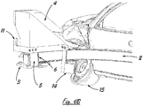
- FIG. 6A this figure most clearly shows the substance of a nominal configuration of an end terminal 1 for a safety guardrail.
- an end terminal 1 comprises an elongated beam 2 which is on opposite ends connected to a ground anchor 3 and to a safety guardrail, respectively.
- the safety guardrail is not shown in the figure, but its construction and its combination with an end terminal 1 as shown in figure 6A is abundantly clear to the skilled person and requires no further elucidation.
- the end terminal 1 comprises a collision catcher 4 which is slidably mounted on the beam 2, wherein the collision catcher 4 connects to a sliding block 5 with an aperture 6 through which the beam 2 is guided.
- FIG 1 the invention is illustrated by a detailed view at the beam 2 and the sliding block 5 with its aperture 6. It is shown in figure 1 that inside the aperture 6 the sliding block 5 is provided with one or more protruding deformation elements 7.
- Figure 1 only provides a view of a single deformation element 7, but it is preferred that at least two deformation elements 7 are provided within the aperture 6 and on the sliding block 5, projecting to opposite sides of the elongated beam 2 reaching through the sliding block 5.
- Figure 2A and figure 2B show from different perspectives how the beam 2 is deformed during a vehicle impact as the sliding block 5 is moved in the direction of arrow A, towards the safety guardrail, along beam 2.
- Beam 2 may be arranged as having an optional initial depressed portion 8 that the deformation elements 7 engage with. This is however not necessary as the beam 2 may also be arranged with a square or rectangular cross-section over its entire length.
- the tensile strength of the elongated beam 2 and the tensile strength of the sliding block 5 are arranged such that upon movement of the sliding block 5 along the beam 2 towards the safety guardrail - that is in the direction of the arrow A - the deformation element or elements 7 provide a depressed portion 8 in the beam 2, or extend an initial depressed portion 8 of the beam 2 towards the safety guardrail.
- the deformation elements 7 deform the beam 2, which takes energy and slows the car down.
- the elongated beam 2 has a substantially square or rectangular cross-section before movement of the sliding block 5, after passing of the sliding block 5 this square or rectangular cross-section is converted by the operation of the deformation elements 7 into a non-square or non-rectangular cross-section with depressed portions 8.
- the sliding block 5 is provided with at least one of upper 5' wall portions inside the aperture 6.
- Whatever wall portions are actually present, these wall portions are intended to directly engage the elongated beam 2 for support of the sliding block 5, and that in or between said at least one of upper 5' and lower 5" wall portions a slit 9 or slits are provided providing room for passing of bolt heads 10 or other fixtures on top of the elongated beam 2.
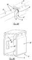
- FIG. 3D an embodiment of a sliding block 5 is shown wherein the sidewalls 15', 15" of the sliding block 5 are provided with indents 16', 16" protruding inwardly into the aperture 6 through which the elongated beam (not shown) is guided, wherein said indents 16', 16" are designed to directly engage the elongated beam for support of the sliding block 5 whilst providing room for passing of bolt heads 10 or other fixtures extending from the elongated beam 2.
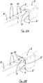
- FIG 4A and figure 4B shows that the collision catcher 4 has a hook part 11.
- Figure 4B shows its function for catching behind a bumper 12 of a colliding car.
- the hook part 11 is upstanding, which has proven to be most effective. It can also be beneficial that the hook part 11 is swivable. Other options are to embody the hook part with a locking pin that breaks under impact.
- the hook part can also be embodied as an active feature which becomes operational upon impact of a car. The way this can be executed requires no further elucidation, and is therefore not further shown in the drawing.
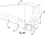
- the elongated beam 2 is provided with an insert beam extending over a part 13 of the length of the elongated beam 2 to provide said elongated beam with portions of different impact resistance.
- the insert beam in part 13 of the elongated beam 2 is closer to the safety guardrail (which is not shown but which is present at the left of the figure), than to the ground anchor 3 in order to provide that upon impact the elongated beam 2 initially provides a lower impact resistance than at a final stage when the part 13 of the elongated beam 2, wherein the insert beam is provided, becomes operational.
- figure 5 only shows a single insert beam, it may be preferable to provide the elongated beam 2 with a plurality of insert beams, wherein the insert beams have mutually differing lengths, gauges and/or material properties. This increases the flexibility in the design to provide the elongated beam with portions of different impact resistance.
- a stander 17 is provided with a U-shaped receptacle 18 in which the elongated beam 2 is received.
- the stander 17 is designed to collapse when the elongated beam 2 is loaded during the impact of a colliding car.
- FIG 6A it is shown near to the collision catcher 4 the end terminal is provided with a deflector 14, wherein the deflector 14 is mounted on and extends below the elongated beam 2.
- the deflector 14 can also be mounted to the ground.
- Figure 6B shows the functionality of the deflector 14 to deflect parts of the vehicle (mainly the wheel 15) back out, away from the anchor 3 to the ground, to prevent such parts from getting wedged and trapped between the underside of the elongated beam 2 and the rigid anchor 3 to the ground.
Description
- The invention relates to an end terminal for a safety guardrail, said end terminal comprising an elongated beam which is on opposite ends connected to a ground anchor and to the safety guardrail, respectively, and further comprising a collision catcher which is slidably mounted on the beam, wherein the collision catcher connects to a sliding block with an aperture through which the beam is guided.
- Such an end terminal for a safety guardrail is known from
EP-B-2 646 624 . This known end terminal for a safety guardrail comprises an energy absorbing device and a metallic, elongated draw element, one of which is connected to the collision catcher, and wherein the impact energy of a collision is absorbed due to a relative movement of the elongated draw element and the energy absorbing device. -
WO 2017 / 125740 A1 also discloses an end terminal, wherein the end terminal is provided with shearing elements projecting into cut-outs to transfer the load from the impact post, as the first point of impact to the shearing elements. The shearing elements cut through the rail upon collision of a vehicle with the impact device. -
US 2003 / 0034484 A1 describes an impact head of a box beam rail member that is provided to bend and deflect the rail member during a collision, allowing the rail member to be deflected away from the roadway and out of the path of an impacting vehicle. The impact head includes a striking face and a chute portion that receives the box beam rail member therewithin when it is telescopingly forced onto the rail member by the collision force. -
US 2006 / 0054876 A1 discloses a vehicle crash cushion with a deformable attenuator member extending in the longitudinal direction and having a first end coupled to the front anchor and a second end coupled to the rear anchor. A support member is positioned adjacent the attenuator member and is moveable in the longitudinal direction relative thereto between an initial position and an impact position toward the rear anchor and away from the front anchor. -
US 2003 / 0070894 A1 discloses a crash cushion system having an impact head and a three stage energy absorption mechanism. -
WO 2016 / 033122 A1 discloses a guardrail terminal incorporating an impact head of open front configuration adapted with a rear portion as a funnel disposed with the narrow end of the funnel facing forward which will flatten the W beam guardrail as it moves down the beam when impacted by the vehicle. - Any end terminal for a safety guardrail is required to pass a series of ENV1317-4:2002 crash tests. The EN1317 European crash test standard is developed within the framework of the Construction Products Directive 89/106/EEC and EN1317-5 serves as a basis for the CE marking of road safety systems such as safety barriers and guardrails, crash cushions, barrier extremities and transitions. One of these tests is a head on impact at 110km/h with a 1500kg car to get a classification in the energy absorbing class of EN1317. In order to achieve this, it is desirable for the vehicle to be decelerated in a smooth manner.
- The invention is that the collision catcher has a hook part, which is preferably upstanding and/or swivable, for catching behind a bumper of a colliding car. As mentioned above an end terminal for a safety guardrail is required to pass EN1317 crash tests. One of these tests in particular causes the car to spin out and away from the end terminal, which can lead to the vehicle rebounding into other road traffic. The EN1317 standard has criteria that must be met to gain successful accreditation. The problem is that the nature of this test is likely to cause the vehicle to spin out beyond limits set in the standard and therefore fail the test. According to the invention a hooked front end is provided on the collision catcher which is designed to 'capture' the front bumper of a vehicle and therefore reduce motion of the vehicle during impact and stay within the limits prescribed by the test standard EN1317. The hook part can also be embodied with a locking pin that breaks under impact. The hook part can also be embodied as an active feature which becomes operational upon impact of a car.
- In a preferred embodiment, inside the aperture the sliding block is provided with one or more protruding deformation elements that engage the beam so as to arrange that upon movement of the sliding block towards the safety guardrail, the deformation elements provide a depressed portion in the beam that extends towards the safety guardrail. As the sliding block moves along the beam during vehicle impact, the deformation elements thus deform the beam, which takes energy and slows the car down.
- For mounting the sliding block on the elongated beam it may be preferable that the elongated beam has an initial depressed portion in which the one or more protruding deformation elements protrude.
- To promote the achievements of the invention it is preferred that the elongated beam has a substantially square or rectangular cross-section, and that at least two deformation elements are provided within the aperture on the sliding block, and projecting to opposite sides of the elongated beam reaching through the sliding block. The sliding block is then mounted in a more or less balanced way on the elongated beam, and the further depression of the elongated beam during impact can then take place on opposite sides of the elongated beam so as to secure the maintenance of a stable movement of the sliding block along the elongated beam during slowing down of the impacting car.
- It is preferred that the sliding block is provided with at least one of upper wall portions inside the aperture that directly engage the elongated beam for support of the sliding block, and that in or between said at least one of upper and lower wall portions a slit or slits are provided providing room for passing of bolt heads or other fixtures extending from the elongated beam. Preferably the sliding block is also provided with at least one of lower wall portions inside the aperture that directly engage the elongated beam for support of the sliding block, and that in or between said at least one of lower wall portions a slit or slits are provided providing room for passing of bolt heads or other fixtures extending from the elongated beam.
- In an preferred embodiment regarding this invention, the sidewalls of the sliding block are provided with indents protruding inwardly into the aperture through which the elongated beam is guided, wherein said indents directly engage the elongated beam for support of the sliding block whilst providing room for passing of bolt heads or other fixtures extending from the elongated beam.
- With respect to the invention it is remarked that, with current state-of-the-art end terminal designs, if a vehicle heavier or travelling at a higher speed than the above-mentioned 1500kg car traveling at 110km/h were to impact the end terminal, once the prescribed energy had been absorbed, the terminal would cease to function in its desired way and could be dangerous. The just mentioned two embodiments relating to the invention are embodied with features which secure that the end terminal will continue to absorb energy beyond the EN1317 requirement for as long as is needed to bring the vehicle to rest. To achieve this result it is instrumental that the sliding block will pass over bolted joints of the elongated beam allowing the end terminal to continue working along its entire length without getting caught up.
- It is preferred that below the elongated beam a stander is provided with a U-shaped receptacle in which the elongated beam is received. The stander with the U-shaped receptacle only supports the elongated beam. This has the advantage that the connection between the stander and the beam is relatively strong in a lateral direction, but relatively weak in a longitudinal direction.
- Preferably the stander is designed to collapse when the elongated beam is loaded during the impact of a colliding car.
- It is preferred that the elongated beam is provided with at least one insert beam extending over a part of the length of the elongated beam to provide said elongated beam with portions of different impact resistance. This differentiates from prior art solutions that are equipped with a single mechanism for absorbing energy and therefore do not have any ability to tailor the resistive force level for different vehicle impacts. According to the invention the at least one insert beam that extends over a part of the length of the elongated beam provides it with different levels of impact resistance, so that one thing and another can be tailored to the required properties of the end terminal.
- The benefits of applying at least one insert beam in the elongated beam can be further promoted by arranging that the elongated beam is provided with a plurality of insert beams, preferably having mutually differing lengths, gauges and/or material properties.
- It is preferable that the at least one insert beam is closer to the safety guardrail than to the ground anchor in order to provide that upon impact the elongated beam initially provides a lower impact resistance than at a final stage when the part of the elongated beam wherein the insert beam is provided becomes operational.
- It is preferred that the end terminal is provided with a deflector, wherein the deflector extends below the elongated beam. This provides a solution for the problem in certain cases of vehicle impact from an opposite rather than from the regular impact side, that the vehicle can become wedged between the underside of the elongated beam and the rigid anchor to the ground. The deflector is arranged to deflect parts of the vehicle (mainly the wheel) back out away from the anchor to the ground, to prevent such parts from getting trapped.
- The deflector can either be mounted on the elongated beam or another suitable part of the end terminal, or to the ground.
- The invention will hereinafter be further elucidated with reference to the drawing of an exemplary embodiment of an apparatus operating according to a prior art method and according to the method of the invention that is not limiting as to the appended claims.
- In the drawing:
-
figure 1 shows a detail of an end terminal for a safety guardrail according to the invention with a view at the sliding block; and -
figure 2A and figure 2B show the sliding block after it has moved over a certain distance along the elongated beam of the end terminal; -
figures 3A - 3C show the sliding block according to a first embodiment after it has moved over a certain distance along the elongated beam of the end terminal, also showing the bolt heads on top of the elongated beam; -
figure 3D shows separately a sliding block according to a second embodiment; -
figure 4A andfigure 4B show the end terminal for a safety guardrail, as provided with an upstanding hook for catching behind the bumper of a car; -
figure 5 shows the end terminal of the invention in a specific embodiment with an insert beam provided in the part of the elongated beam; and -
figure 6A andfigure 6B respectively show the end terminal of the invention as provided with a deflector in rest, and after impact with a colliding car. - Whenever in the figures the same reference numerals are applied, these numerals refer to the same parts.
- Making first reference to
figure 6A , this figure most clearly shows the substance of a nominal configuration of an end terminal 1 for a safety guardrail. Such an end terminal 1 comprises anelongated beam 2 which is on opposite ends connected to aground anchor 3 and to a safety guardrail, respectively. The safety guardrail is not shown in the figure, but its construction and its combination with an end terminal 1 as shown infigure 6A is abundantly clear to the skilled person and requires no further elucidation. The end terminal 1 comprises acollision catcher 4 which is slidably mounted on thebeam 2, wherein thecollision catcher 4 connects to asliding block 5 with anaperture 6 through which thebeam 2 is guided. - Turning now to
figure 1 , the invention is illustrated by a detailed view at thebeam 2 and thesliding block 5 with itsaperture 6. It is shown infigure 1 that inside theaperture 6 thesliding block 5 is provided with one or moreprotruding deformation elements 7.Figure 1 only provides a view of asingle deformation element 7, but it is preferred that at least twodeformation elements 7 are provided within theaperture 6 and on thesliding block 5, projecting to opposite sides of theelongated beam 2 reaching through thesliding block 5. -
Figure 2A and figure 2B show from different perspectives how thebeam 2 is deformed during a vehicle impact as thesliding block 5 is moved in the direction of arrow A, towards the safety guardrail, alongbeam 2.Beam 2 may be arranged as having an optional initialdepressed portion 8 that thedeformation elements 7 engage with. This is however not necessary as thebeam 2 may also be arranged with a square or rectangular cross-section over its entire length. - There are no specific requirements as to the tensile strength of the
elongated beam 2 and the tensile strength of the slidingblock 5, as long as thebeam 2 and the slidingblock 5 are arranged such that upon movement of the slidingblock 5 along thebeam 2 towards the safety guardrail - that is in the direction of the arrow A - the deformation element orelements 7 provide adepressed portion 8 in thebeam 2, or extend an initialdepressed portion 8 of thebeam 2 towards the safety guardrail. As the sliding block moves along thebeam 2 during vehicle impact, thedeformation elements 7 deform thebeam 2, which takes energy and slows the car down. As theelongated beam 2 has a substantially square or rectangular cross-section before movement of the slidingblock 5, after passing of the slidingblock 5 this square or rectangular cross-section is converted by the operation of thedeformation elements 7 into a non-square or non-rectangular cross-section withdepressed portions 8. - Taking reference now to
figures 3A - 3C it is shown that the slidingblock 5 is provided with at least one of upper 5' wall portions inside theaperture 6. Preferably also at least one oflower wall portions 5" are provided. This means that not both upper 5' and lower 5" wall portions need to be present, but that it is preferred that at least one of the upper wall portions 5' and at least one oflower wall portions 5" are provided. Whatever wall portions are actually present, these wall portions are intended to directly engage theelongated beam 2 for support of the slidingblock 5, and that in or between said at least one of upper 5' and lower 5" wall portions aslit 9 or slits are provided providing room for passing of bolt heads 10 or other fixtures on top of theelongated beam 2. Going fromfigure 3A to figure 3C the progressing movement of the slidingblock 5 along theelongated beam 2 is shown, wherein the bolt heads 10 can pass through theupper slit 9 between the two adjacent upper wall portions 5'. A similar construction can be provided at the underside of thebeam 2 wherein alower slit 9 can be provided between the optionallower wall portions 5". This is not visible in thefigures 3A - 3C but entirely clear for the skilled person, so that a further elucidation is superfluous. - In an preferred embodiment shown in
figure 3D an embodiment of a slidingblock 5 is shown wherein thesidewalls 15', 15" of the slidingblock 5 are provided withindents 16', 16" protruding inwardly into theaperture 6 through which the elongated beam (not shown) is guided, wherein said indents 16', 16" are designed to directly engage the elongated beam for support of the slidingblock 5 whilst providing room for passing of bolt heads 10 or other fixtures extending from theelongated beam 2. - Turning now to
figure 4A andfigure 4B it shows that thecollision catcher 4 has ahook part 11.Figure 4B shows its function for catching behind abumper 12 of a colliding car. - Preferably the
hook part 11 is upstanding, which has proven to be most effective. It can also be beneficial that thehook part 11 is swivable. Other options are to embody the hook part with a locking pin that breaks under impact. The hook part can also be embodied as an active feature which becomes operational upon impact of a car. The way this can be executed requires no further elucidation, and is therefore not further shown in the drawing. - In
figure 5 it is indicated that theelongated beam 2 is provided with an insert beam extending over apart 13 of the length of theelongated beam 2 to provide said elongated beam with portions of different impact resistance. As will be clear fromfigure 5 , the insert beam inpart 13 of theelongated beam 2 is closer to the safety guardrail (which is not shown but which is present at the left of the figure), than to theground anchor 3 in order to provide that upon impact theelongated beam 2 initially provides a lower impact resistance than at a final stage when thepart 13 of theelongated beam 2, wherein the insert beam is provided, becomes operational. Althoughfigure 5 only shows a single insert beam, it may be preferable to provide theelongated beam 2 with a plurality of insert beams, wherein the insert beams have mutually differing lengths, gauges and/or material properties. This increases the flexibility in the design to provide the elongated beam with portions of different impact resistance. - As another feature shown in
figure 5 , below the elongated beam 2 astander 17 is provided with aU-shaped receptacle 18 in which theelongated beam 2 is received. Preferably thestander 17 is designed to collapse when theelongated beam 2 is loaded during the impact of a colliding car. - Turning back to
figure 6A , it is shown near to thecollision catcher 4 the end terminal is provided with adeflector 14, wherein thedeflector 14 is mounted on and extends below theelongated beam 2. Alternatively thedeflector 14 can also be mounted to the ground.Figure 6B shows the functionality of thedeflector 14 to deflect parts of the vehicle (mainly the wheel 15) back out, away from theanchor 3 to the ground, to prevent such parts from getting wedged and trapped between the underside of theelongated beam 2 and therigid anchor 3 to the ground. - Although the invention has been discussed in the foregoing with reference to exemplary embodiments of the end terminal for a safety guard of the invention, the invention is not restricted to these particular embodiments which can be varied in many ways without departing from the invention. The discussed exemplary embodiments shall therefore not be used to construe the appended claims strictly in accordance therewith. On the contrary the embodiments are merely intended to explain the wording of the appended claims without intent to limit the claims to these exemplary embodiments. The scope of protection of the invention shall therefore be construed in accordance with the appended claims only, wherein a possible ambiguity in the wording of the claims shall be resolved using these exemplary embodiments.
Claims (15)
- End terminal (1) for a safety guardrail, said end terminal (1) comprising an elongated beam (2) which is on opposite ends connected to a ground anchor (3) and to the safety guardrail, respectively, and further comprising a collision catcher (4) which is slidably mounted on the beam (2), wherein the collision catcher (4) connects to a sliding block (5) with an aperture (6) through which the beam (2) is guided, characterized in that the collision catcher (4) has a hook part (11)for catching behind a bumper (12) of a colliding car.
- End terminal according to claim 1, characterized in that the hook part (11) is an upstanding hook part.
- End terminal according to claim 1 or 2, characterized in that inside the aperture (6) the sliding block (5) is provided with one or more protruding deformation elements (7) that engage the beam (2) so as to arrange that upon movement of the sliding block (5) towards the safety guardrail, the deformation elements (7) provide a depressed portion (8) in the beam (2) that extends towards the safety guardrail.
- End terminal according to any one of claims 1 - 3, characterized in that the elongated beam (2) has an initial depressed portion (8) in which the one or more protruding deformation elements (7) protrude.
- End terminal according to any one of claims 1 - 4, characterized in that the elongated beam (2) has a substantially square or rectangular cross-section, and that at least two deformation elements (7) are provided within the aperture (6) on the sliding block (5), and projecting to opposite sides of the elongated beam (2) reaching through the sliding block (5).
- End terminal according to any one of claims 1 - 5, characterized in that the sliding block (5) is provided with at least one of upper (5') wall portions inside the aperture (6) that directly engage the elongated beam (2) for support of the sliding block (5), and that in or between said at least one of upper (5') wall portions a slit (9) or slits are provided providing room for passing of bolt heads (10) or other fixtures extending from the elongated beam (2).
- End terminal according to claim 6, characterized in that the sliding block (5) is also provided with at least one of lower (5") wall portions inside the aperture (6) that directly engage the elongated beam (2) for support of the sliding block (5), and that in or between said at least one of lower (5") wall portions a slit (9) or slits are provided providing room for passing of bolt heads (10) or other fixtures extending from the elongated beam (2).
- End terminal according to any one of claims 1 - 7, characterized in that the sidewalls (15', 15") of the sliding block (5) are provided with indents (16', 16") protruding inwardly into the aperture (6) through which the elongated beam (2) is guided, wherein said indents (16', 16") directly engage the elongated beam (2) for support of the sliding block (5) whilst providing room for passing of bolt heads (10) or other fixtures extending from the elongated beam (2).
- End terminal according to any one of claims 1 - 8, characterized in that below the elongated beam (2) a stander (17) is provided with a U-shaped receptacle (18) in which the elongated beam (2) is received.
- End terminal according to claim 9, characterized in that the stander (17) is designed to collapse when the elongated beam (2) is loaded during the impact of a colliding car.
- End terminal according to any one of claims 1 - 10, characterized in that the elongated beam (2) is provided with at least one insert beam extending over a part (13) of the length of the elongated beam (2) to provide said elongated beam (2) with portions of different impact resistance.
- End terminal according to claim 11, characterized in that the insert beams have mutually differing lengths, gauges and/or material properties.
- End terminal according to any one of claims 11 - 12, characterized in that the at least one insert beam is closer to the safety guardrail than to the ground anchor (3) in order to provide that upon impact the elongated beam (2) initially provides a lower impact resistance than at a final stage when the part (13) of the elongated beam (2) wherein the at least one insert beam is provided becomes operational.
- End terminal according to any one of claims 1 - 13, characterized in that the end terminal (1) is provided with a deflector (14), wherein the deflector (14) extends below the elongated beam (2).
- End terminal according to claim 14, characterized in that the deflector (14) is mounted to the ground.
Priority Applications (3)
| Application Number | Priority Date | Filing Date | Title |
|---|---|---|---|
| EP19209622.0A EP3660218B1 (en) | 2018-11-26 | 2018-11-26 | End terminal for a safety guardrail |
| PL19209622T PL3660218T3 (en) | 2018-11-26 | 2018-11-26 | End terminal for a safety guardrail |
| DK19209622.0T DK3660218T3 (en) | 2018-11-26 | 2018-11-26 | Endeterminal til et autoværn |
Applications Claiming Priority (2)
| Application Number | Priority Date | Filing Date | Title |
|---|---|---|---|
| EP18208381.6A EP3656924B1 (en) | 2018-11-26 | 2018-11-26 | End terminal for a safety guardrail |
| EP19209622.0A EP3660218B1 (en) | 2018-11-26 | 2018-11-26 | End terminal for a safety guardrail |
Related Parent Applications (2)
| Application Number | Title | Priority Date | Filing Date |
|---|---|---|---|
| EP18208381.6A Division-Into EP3656924B1 (en) | 2018-11-26 | 2018-11-26 | End terminal for a safety guardrail |
| EP18208381.6A Division EP3656924B1 (en) | 2018-11-26 | 2018-11-26 | End terminal for a safety guardrail |
Publications (2)
| Publication Number | Publication Date |
|---|---|
| EP3660218A1 EP3660218A1 (en) | 2020-06-03 |
| EP3660218B1 true EP3660218B1 (en) | 2021-08-25 |
Family
ID=64477058
Family Applications (4)
| Application Number | Title | Priority Date | Filing Date |
|---|---|---|---|
| EP18208381.6A Active EP3656924B1 (en) | 2018-11-26 | 2018-11-26 | End terminal for a safety guardrail |
| EP19209622.0A Active EP3660218B1 (en) | 2018-11-26 | 2018-11-26 | End terminal for a safety guardrail |
| EP19209619.6A Active EP3656925B1 (en) | 2018-11-26 | 2018-11-26 | End terminal for a safety guardrail |
| EP19209624.6A Active EP3660219B1 (en) | 2018-11-26 | 2018-11-26 | End terminal for a safety guardrail |
Family Applications Before (1)
| Application Number | Title | Priority Date | Filing Date |
|---|---|---|---|
| EP18208381.6A Active EP3656924B1 (en) | 2018-11-26 | 2018-11-26 | End terminal for a safety guardrail |
Family Applications After (2)
| Application Number | Title | Priority Date | Filing Date |
|---|---|---|---|
| EP19209619.6A Active EP3656925B1 (en) | 2018-11-26 | 2018-11-26 | End terminal for a safety guardrail |
| EP19209624.6A Active EP3660219B1 (en) | 2018-11-26 | 2018-11-26 | End terminal for a safety guardrail |
Country Status (3)
| Country | Link |
|---|---|
| EP (4) | EP3656924B1 (en) |
| DK (4) | DK3656924T3 (en) |
| PL (4) | PL3660219T3 (en) |
Families Citing this family (1)
| Publication number | Priority date | Publication date | Assignee | Title |
|---|---|---|---|---|
| WO2023055260A1 (en) * | 2021-10-01 | 2023-04-06 | Открытое Акционерное Общество "Завод Продмаш" | Road energy-absorbing assembly and road frontal impact barrier |
Family Cites Families (10)
| Publication number | Priority date | Publication date | Assignee | Title |
|---|---|---|---|---|
| US20030070894A1 (en) | 1999-05-07 | 2003-04-17 | Reid John D. | Single-sided crash cushion system |
| DE60224881D1 (en) | 2001-07-20 | 2008-03-20 | Texas A & M Univ Sys | PLANE FINISHING AREA OF A BOX BALANCE |
| BRPI0515324A (en) * | 2004-09-15 | 2008-07-22 | Energy Absorption System | shock absorber |
| US7694941B2 (en) * | 2008-05-05 | 2010-04-13 | The Texas A&M University System | Guardrail safety system for dissipating energy to decelerate the impacting vehicle |
| CN201730069U (en) * | 2010-08-16 | 2011-02-02 | 北京中路安交通科技有限公司 | Guidable outer frame crash cushion with internal energy-absorbing boards |
| SE535428C2 (en) | 2010-12-02 | 2012-08-07 | Birstaverken Ab | Vehicle collision protection including an energy-absorbing device |
| US10036132B2 (en) | 2013-08-26 | 2018-07-31 | Dean L. Sicking | Twist box guardrail terminal |
| GB201601141D0 (en) | 2016-01-21 | 2016-03-09 | Hill & Smith Holdings Plc | Energy absorbing terminal system |
| US9739328B1 (en) * | 2016-02-12 | 2017-08-22 | Verdegro Holding B.V. | Impact attenuator and vehicle, trailer and guardrail comprising such an impact attenuator |
| MX2018016375A (en) * | 2018-01-23 | 2020-07-28 | Valmont Highway International Pty Ltd | Improvements in and relating to road safety rail sysyems and parts and fittings therefor. |
-
2018
- 2018-11-26 DK DK18208381.6T patent/DK3656924T3/en active
- 2018-11-26 DK DK19209624.6T patent/DK3660219T3/en active
- 2018-11-26 EP EP18208381.6A patent/EP3656924B1/en active Active
- 2018-11-26 EP EP19209622.0A patent/EP3660218B1/en active Active
- 2018-11-26 DK DK19209619.6T patent/DK3656925T3/en active
- 2018-11-26 PL PL19209624T patent/PL3660219T3/en unknown
- 2018-11-26 PL PL19209622T patent/PL3660218T3/en unknown
- 2018-11-26 EP EP19209619.6A patent/EP3656925B1/en active Active
- 2018-11-26 DK DK19209622.0T patent/DK3660218T3/en active
- 2018-11-26 PL PL19209619T patent/PL3656925T3/en unknown
- 2018-11-26 EP EP19209624.6A patent/EP3660219B1/en active Active
- 2018-11-26 PL PL18208381.6T patent/PL3656924T3/en unknown
Also Published As
| Publication number | Publication date |
|---|---|
| EP3660219A1 (en) | 2020-06-03 |
| EP3656924B1 (en) | 2022-06-22 |
| PL3656925T3 (en) | 2022-06-20 |
| EP3656925A1 (en) | 2020-05-27 |
| DK3656924T3 (en) | 2022-09-12 |
| DK3656925T3 (en) | 2021-11-15 |
| PL3660219T3 (en) | 2022-05-02 |
| EP3660219B1 (en) | 2022-01-05 |
| PL3660218T3 (en) | 2021-12-27 |
| EP3656924A1 (en) | 2020-05-27 |
| EP3660218A1 (en) | 2020-06-03 |
| EP3656925B1 (en) | 2021-08-25 |
| DK3660219T3 (en) | 2022-04-11 |
| DK3660218T3 (en) | 2021-11-15 |
| PL3656924T3 (en) | 2023-01-09 |
Similar Documents
| Publication | Publication Date | Title |
|---|---|---|
| RU2231462C2 (en) | Rail vehicle with driver's cabin of energy absorbing design made for taking up collision forces action onto cabin at level higher than vehicle frame | |
| EP1133601B1 (en) | Collision safety device | |
| CN108699790B (en) | Crash attenuator and vehicle, trailer and guard rail comprising such a crash attenuator | |
| EP2077354B1 (en) | Crash attenuator | |
| US7694941B2 (en) | Guardrail safety system for dissipating energy to decelerate the impacting vehicle | |
| US7883075B2 (en) | Tension guardrail terminal | |
| KR101972549B1 (en) | Impact attenuator for vehicles | |
| EP2313560B1 (en) | Guardrail safety system for dissipating energy to decelerate the impacting vehicle | |
| KR20140021951A (en) | Vehicle crash attenuator apparatus | |
| EP3186444B1 (en) | Twist box guardrail terminal | |
| EP3660218B1 (en) | End terminal for a safety guardrail | |
| US10851503B2 (en) | Tension end treatment for guardrail safety system | |
| KR101328677B1 (en) | A guardrail | |
| RU2791316C1 (en) | Road energy-absorbing assembly and road frontal fence | |
| KR102640394B1 (en) | Truck mounted attenuator | |
| WO2023055260A1 (en) | Road energy-absorbing assembly and road frontal impact barrier | |
| KR101184290B1 (en) | Method of guardrail stiffness regulation for occupant safety index reduction and device thereof | |
| KR101909505B1 (en) | Impact attenuator by release of resistant part |
Legal Events
| Date | Code | Title | Description |
|---|---|---|---|
| PUAI | Public reference made under article 153(3) epc to a published international application that has entered the european phase |
Free format text: ORIGINAL CODE: 0009012 |
|
| STAA | Information on the status of an ep patent application or granted ep patent |
Free format text: STATUS: THE APPLICATION HAS BEEN PUBLISHED |
|
| AC | Divisional application: reference to earlier application |
Ref document number: 3656924 Country of ref document: EP Kind code of ref document: P |
|
| AK | Designated contracting states |
Kind code of ref document: A1 Designated state(s): AL AT BE BG CH CY CZ DE DK EE ES FI FR GB GR HR HU IE IS IT LI LT LU LV MC MK MT NL NO PL PT RO RS SE SI SK SM TR |
|
| AX | Request for extension of the european patent |
Extension state: BA ME |
|
| STAA | Information on the status of an ep patent application or granted ep patent |
Free format text: STATUS: REQUEST FOR EXAMINATION WAS MADE |
|
| 17P | Request for examination filed |
Effective date: 20201203 |
|
| RBV | Designated contracting states (corrected) |
Designated state(s): AL AT BE BG CH CY CZ DE DK EE ES FI FR GB GR HR HU IE IS IT LI LT LU LV MC MK MT NL NO PL PT RO RS SE SI SK SM TR |
|
| GRAP | Despatch of communication of intention to grant a patent |
Free format text: ORIGINAL CODE: EPIDOSNIGR1 |
|
| STAA | Information on the status of an ep patent application or granted ep patent |
Free format text: STATUS: GRANT OF PATENT IS INTENDED |
|
| INTG | Intention to grant announced |
Effective date: 20210406 |
|
| GRAS | Grant fee paid |
Free format text: ORIGINAL CODE: EPIDOSNIGR3 |
|
| GRAA | (expected) grant |
Free format text: ORIGINAL CODE: 0009210 |
|
| STAA | Information on the status of an ep patent application or granted ep patent |
Free format text: STATUS: THE PATENT HAS BEEN GRANTED |
|
| AC | Divisional application: reference to earlier application |
Ref document number: 3656924 Country of ref document: EP Kind code of ref document: P |
|
| AK | Designated contracting states |
Kind code of ref document: B1 Designated state(s): AL AT BE BG CH CY CZ DE DK EE ES FI FR GB GR HR HU IE IS IT LI LT LU LV MC MK MT NL NO PL PT RO RS SE SI SK SM TR |
|
| REG | Reference to a national code |
Ref country code: CH Ref legal event code: EP |
|
| REG | Reference to a national code |
Ref country code: IE Ref legal event code: FG4D Ref country code: AT Ref legal event code: REF Ref document number: 1423922 Country of ref document: AT Kind code of ref document: T Effective date: 20210915 |
|
| REG | Reference to a national code |
Ref country code: DE Ref legal event code: R096 Ref document number: 602018022621 Country of ref document: DE |
|
| REG | Reference to a national code |
Ref country code: FI Ref legal event code: FGE |
|
| REG | Reference to a national code |
Ref country code: DK Ref legal event code: T3 Effective date: 20211111 |
|
| REG | Reference to a national code |
Ref country code: NO Ref legal event code: T2 Effective date: 20210825 |
|
| REG | Reference to a national code |
Ref country code: SE Ref legal event code: TRGR |
|
| REG | Reference to a national code |
Ref country code: NL Ref legal event code: FP |
|
| REG | Reference to a national code |
Ref country code: LT Ref legal event code: MG9D |
|
| REG | Reference to a national code |
Ref country code: AT Ref legal event code: MK05 Ref document number: 1423922 Country of ref document: AT Kind code of ref document: T Effective date: 20210825 |
|
| PG25 | Lapsed in a contracting state [announced via postgrant information from national office to epo] |
Ref country code: RS Free format text: LAPSE BECAUSE OF FAILURE TO SUBMIT A TRANSLATION OF THE DESCRIPTION OR TO PAY THE FEE WITHIN THE PRESCRIBED TIME-LIMIT Effective date: 20210825 Ref country code: ES Free format text: LAPSE BECAUSE OF FAILURE TO SUBMIT A TRANSLATION OF THE DESCRIPTION OR TO PAY THE FEE WITHIN THE PRESCRIBED TIME-LIMIT Effective date: 20210825 Ref country code: HR Free format text: LAPSE BECAUSE OF FAILURE TO SUBMIT A TRANSLATION OF THE DESCRIPTION OR TO PAY THE FEE WITHIN THE PRESCRIBED TIME-LIMIT Effective date: 20210825 Ref country code: PT Free format text: LAPSE BECAUSE OF FAILURE TO SUBMIT A TRANSLATION OF THE DESCRIPTION OR TO PAY THE FEE WITHIN THE PRESCRIBED TIME-LIMIT Effective date: 20211227 Ref country code: AT Free format text: LAPSE BECAUSE OF FAILURE TO SUBMIT A TRANSLATION OF THE DESCRIPTION OR TO PAY THE FEE WITHIN THE PRESCRIBED TIME-LIMIT Effective date: 20210825 Ref country code: BG Free format text: LAPSE BECAUSE OF FAILURE TO SUBMIT A TRANSLATION OF THE DESCRIPTION OR TO PAY THE FEE WITHIN THE PRESCRIBED TIME-LIMIT Effective date: 20211125 Ref country code: LT Free format text: LAPSE BECAUSE OF FAILURE TO SUBMIT A TRANSLATION OF THE DESCRIPTION OR TO PAY THE FEE WITHIN THE PRESCRIBED TIME-LIMIT Effective date: 20210825 |
|
| PG25 | Lapsed in a contracting state [announced via postgrant information from national office to epo] |
Ref country code: LV Free format text: LAPSE BECAUSE OF FAILURE TO SUBMIT A TRANSLATION OF THE DESCRIPTION OR TO PAY THE FEE WITHIN THE PRESCRIBED TIME-LIMIT Effective date: 20210825 Ref country code: GR Free format text: LAPSE BECAUSE OF FAILURE TO SUBMIT A TRANSLATION OF THE DESCRIPTION OR TO PAY THE FEE WITHIN THE PRESCRIBED TIME-LIMIT Effective date: 20211126 |
|
| REG | Reference to a national code |
Ref country code: DE Ref legal event code: R097 Ref document number: 602018022621 Country of ref document: DE |
|
| PG25 | Lapsed in a contracting state [announced via postgrant information from national office to epo] |
Ref country code: SM Free format text: LAPSE BECAUSE OF FAILURE TO SUBMIT A TRANSLATION OF THE DESCRIPTION OR TO PAY THE FEE WITHIN THE PRESCRIBED TIME-LIMIT Effective date: 20210825 Ref country code: SK Free format text: LAPSE BECAUSE OF FAILURE TO SUBMIT A TRANSLATION OF THE DESCRIPTION OR TO PAY THE FEE WITHIN THE PRESCRIBED TIME-LIMIT Effective date: 20210825 Ref country code: RO Free format text: LAPSE BECAUSE OF FAILURE TO SUBMIT A TRANSLATION OF THE DESCRIPTION OR TO PAY THE FEE WITHIN THE PRESCRIBED TIME-LIMIT Effective date: 20210825 Ref country code: EE Free format text: LAPSE BECAUSE OF FAILURE TO SUBMIT A TRANSLATION OF THE DESCRIPTION OR TO PAY THE FEE WITHIN THE PRESCRIBED TIME-LIMIT Effective date: 20210825 Ref country code: CZ Free format text: LAPSE BECAUSE OF FAILURE TO SUBMIT A TRANSLATION OF THE DESCRIPTION OR TO PAY THE FEE WITHIN THE PRESCRIBED TIME-LIMIT Effective date: 20210825 Ref country code: AL Free format text: LAPSE BECAUSE OF FAILURE TO SUBMIT A TRANSLATION OF THE DESCRIPTION OR TO PAY THE FEE WITHIN THE PRESCRIBED TIME-LIMIT Effective date: 20210825 |
|
| PG25 | Lapsed in a contracting state [announced via postgrant information from national office to epo] |
Ref country code: MC Free format text: LAPSE BECAUSE OF FAILURE TO SUBMIT A TRANSLATION OF THE DESCRIPTION OR TO PAY THE FEE WITHIN THE PRESCRIBED TIME-LIMIT Effective date: 20210825 |
|
| REG | Reference to a national code |
Ref country code: CH Ref legal event code: PL |
|
| PLBE | No opposition filed within time limit |
Free format text: ORIGINAL CODE: 0009261 |
|
| STAA | Information on the status of an ep patent application or granted ep patent |
Free format text: STATUS: NO OPPOSITION FILED WITHIN TIME LIMIT |
|
| PG25 | Lapsed in a contracting state [announced via postgrant information from national office to epo] |
Ref country code: LU Free format text: LAPSE BECAUSE OF NON-PAYMENT OF DUE FEES Effective date: 20211126 |
|
| 26N | No opposition filed |
Effective date: 20220527 |
|
| PG25 | Lapsed in a contracting state [announced via postgrant information from national office to epo] |
Ref country code: SI Free format text: LAPSE BECAUSE OF FAILURE TO SUBMIT A TRANSLATION OF THE DESCRIPTION OR TO PAY THE FEE WITHIN THE PRESCRIBED TIME-LIMIT Effective date: 20210825 Ref country code: LI Free format text: LAPSE BECAUSE OF NON-PAYMENT OF DUE FEES Effective date: 20211130 Ref country code: CH Free format text: LAPSE BECAUSE OF NON-PAYMENT OF DUE FEES Effective date: 20211130 |
|
| PGFP | Annual fee paid to national office [announced via postgrant information from national office to epo] |
Ref country code: BE Payment date: 20221101 Year of fee payment: 5 |
|
| PGFP | Annual fee paid to national office [announced via postgrant information from national office to epo] |
Ref country code: PL Payment date: 20230227 Year of fee payment: 5 |
|
| PG25 | Lapsed in a contracting state [announced via postgrant information from national office to epo] |
Ref country code: CY Free format text: LAPSE BECAUSE OF FAILURE TO SUBMIT A TRANSLATION OF THE DESCRIPTION OR TO PAY THE FEE WITHIN THE PRESCRIBED TIME-LIMIT Effective date: 20210825 |
|
| PG25 | Lapsed in a contracting state [announced via postgrant information from national office to epo] |
Ref country code: HU Free format text: LAPSE BECAUSE OF FAILURE TO SUBMIT A TRANSLATION OF THE DESCRIPTION OR TO PAY THE FEE WITHIN THE PRESCRIBED TIME-LIMIT; INVALID AB INITIO Effective date: 20181126 |
|
| PGFP | Annual fee paid to national office [announced via postgrant information from national office to epo] |
Ref country code: NL Payment date: 20231121 Year of fee payment: 6 |
|
| PGFP | Annual fee paid to national office [announced via postgrant information from national office to epo] |
Ref country code: GB Payment date: 20231120 Year of fee payment: 6 |
|
| PGFP | Annual fee paid to national office [announced via postgrant information from national office to epo] |
Ref country code: SE Payment date: 20231120 Year of fee payment: 6 Ref country code: NO Payment date: 20231124 Year of fee payment: 6 Ref country code: IT Payment date: 20231123 Year of fee payment: 6 Ref country code: IE Payment date: 20231123 Year of fee payment: 6 Ref country code: FR Payment date: 20231129 Year of fee payment: 6 Ref country code: FI Payment date: 20231129 Year of fee payment: 6 Ref country code: DK Payment date: 20231129 Year of fee payment: 6 Ref country code: DE Payment date: 20231127 Year of fee payment: 6 |
|
| PGFP | Annual fee paid to national office [announced via postgrant information from national office to epo] |
Ref country code: PL Payment date: 20231103 Year of fee payment: 6 Ref country code: BE Payment date: 20231122 Year of fee payment: 6 |