EP3660193A1 - Clothes drying appliance - Google Patents
Clothes drying appliance Download PDFInfo
- Publication number
- EP3660193A1 EP3660193A1 EP19207993.7A EP19207993A EP3660193A1 EP 3660193 A1 EP3660193 A1 EP 3660193A1 EP 19207993 A EP19207993 A EP 19207993A EP 3660193 A1 EP3660193 A1 EP 3660193A1
- Authority
- EP
- European Patent Office
- Prior art keywords
- tub
- rear wall
- drum
- fluid channel
- wall
- Prior art date
- Legal status (The legal status is an assumption and is not a legal conclusion. Google has not performed a legal analysis and makes no representation as to the accuracy of the status listed.)
- Ceased
Links
Images


Classifications
-
- D—TEXTILES; PAPER
- D06—TREATMENT OF TEXTILES OR THE LIKE; LAUNDERING; FLEXIBLE MATERIALS NOT OTHERWISE PROVIDED FOR
- D06F—LAUNDERING, DRYING, IRONING, PRESSING OR FOLDING TEXTILE ARTICLES
- D06F58/00—Domestic laundry dryers
- D06F58/02—Domestic laundry dryers having dryer drums rotating about a horizontal axis
-
- D—TEXTILES; PAPER
- D06—TREATMENT OF TEXTILES OR THE LIKE; LAUNDERING; FLEXIBLE MATERIALS NOT OTHERWISE PROVIDED FOR
- D06F—LAUNDERING, DRYING, IRONING, PRESSING OR FOLDING TEXTILE ARTICLES
- D06F25/00—Washing machines with receptacles, e.g. perforated, having a rotary movement, e.g. oscillatory movement, the receptacle serving both for washing and for centrifugally separating water from the laundry and having further drying means, e.g. using hot air
-
- D—TEXTILES; PAPER
- D06—TREATMENT OF TEXTILES OR THE LIKE; LAUNDERING; FLEXIBLE MATERIALS NOT OTHERWISE PROVIDED FOR
- D06F—LAUNDERING, DRYING, IRONING, PRESSING OR FOLDING TEXTILE ARTICLES
- D06F37/00—Details specific to washing machines covered by groups D06F21/00 - D06F25/00
- D06F37/26—Casings; Tubs
- D06F37/267—Tubs specially adapted for mounting thereto components or devices not provided for in preceding subgroups
-
- D—TEXTILES; PAPER
- D06—TREATMENT OF TEXTILES OR THE LIKE; LAUNDERING; FLEXIBLE MATERIALS NOT OTHERWISE PROVIDED FOR
- D06F—LAUNDERING, DRYING, IRONING, PRESSING OR FOLDING TEXTILE ARTICLES
- D06F58/00—Domestic laundry dryers
- D06F58/20—General details of domestic laundry dryers
-
- D—TEXTILES; PAPER
- D06—TREATMENT OF TEXTILES OR THE LIKE; LAUNDERING; FLEXIBLE MATERIALS NOT OTHERWISE PROVIDED FOR
- D06F—LAUNDERING, DRYING, IRONING, PRESSING OR FOLDING TEXTILE ARTICLES
- D06F58/00—Domestic laundry dryers
- D06F58/20—General details of domestic laundry dryers
- D06F58/24—Condensing arrangements
-
- D—TEXTILES; PAPER
- D06—TREATMENT OF TEXTILES OR THE LIKE; LAUNDERING; FLEXIBLE MATERIALS NOT OTHERWISE PROVIDED FOR
- D06F—LAUNDERING, DRYING, IRONING, PRESSING OR FOLDING TEXTILE ARTICLES
- D06F58/00—Domestic laundry dryers
- D06F58/02—Domestic laundry dryers having dryer drums rotating about a horizontal axis
- D06F58/04—Details
Definitions
- the present invention belongs to the field of household appliance technologies, and relates to a clothes drying appliance, and in particular, to a clothes drying appliance having a heat exchange device.
- a clothes dryer having a clothes processing barrel assembly located in a box, including a rotatable drum driven by a motor and a tub sleeved on the drum.
- the tub is connected to and in communication with a condensate channel.
- the condensate channel is further connected to a fan and an air heating channel sequentially.
- the other end of the air heating channel is further in communication with the tub. Therefore, an air circulation path is formed in the tub, the condensate channel, the fan and the air heating channel.
- a heater in the air heating channel heats drying air flowing through.
- the heated high-temperature drying air enters the clothes processing barrel assembly under the effect of the fan, and wet clothes in the drum are heated, to evaporate moisture in the clothes.
- the drying air carries the evaporated moisture and enters the condensate channel, in which the moisture in the drying air is condensed and returned to a liquid state, and separated from the drying air, so that the drying air becomes cold and dry again, and re-enters the heating channel driven by the fan. Then a new cycle is started and repeats again and again to finally dry the clothes in the drum.
- the condensate channel is connected to a water inlet pipe of cooling water. In the drying process, the cooling water flows into the condensate channel from the water inlet pipe, to exchange heat with the drying air entering the condensate channel, and condensate the moisture in the drying air.
- the US Patent Application No. US6279357B1 discloses a washer dryer.
- the washer dryer includes a cylinder installed in a tub by using a spider.
- a rear wall of the tub includes a recess.
- a drying mode when the cylinder rotates, moist air is drawn from the cylinder and is agitated. The flowing water is in contact with the moist air, to improve an air condensation effect before the air is heated and returned to the cylinder along a circulation channel.
- An objective of the present invention is to provide a clothes drying appliance having a compact structure and high drying efficiency.
- a clothes drying appliance including a drum disposed in a horizontal or an inclined manner, rotatably located in a tub, where a wall of the drum includes a plurality of densely distributed holes, allowing process air engaged in drying to circulate between the drum and the tub, a rear wall of the drum is connected to a drive shaft for driving the drum to rotate, the drive shaft passes through a bearing on a rear wall of the tub, the tub is connected to a process air channel, a fan is disposed in the process air channel, an inlet of the process air channel is located on the rear wall of the tub or close to the rear wall of the tub, a heat exchange device is disposed between the rear wall of the tub and the rear wall of the drum, the heat exchange device includes a flat body, the body includes a flatly distributed fluid channel, and the fluid channel includes an outlet and an inlet, suitable for receiving a cooling medium to enter the fluid channel from the inlet, and for the cooling medium to leave the fluid channel from the outlet, where at least part of the
- the inlet of the process air channel is located on the rear wall of the tub or close to the rear wall of the tub, so that dense process air flow is generated between the rear wall of the drum and the rear wall of the tub, at which the heat exchange device is disposed to save the space, and provide higher drying efficiency.
- a cooling medium is circulated in the fluid channel, so that no splashing or entering the process air channel occurs under the effect the process air.
- the body includes a through hole, the fluid channel is distributed around the through hole, and the drive shaft passes through the through hole of the heat exchange device.
- two sides of the through hole respectively include at least one fluid channel.
- the body includes a first wall facing the rear wall of the drum and a second wall facing the rear wall of the tub, where the first wall is in a smooth structure and the second wall is fixed on the rear wall of the tub.
- the smooth first wall is to avoid affecting a heat exchange effect by preventing fluffs carried in the process air in the drying process from adhering to.
- the first wall is fixed on the rear wall of the tub, so that an unsmooth structure, such as a recess, may be disposed on the second wall.
- the first wall is made of a metal or a material with no less thermal conductivity than a metal.
- the fluid channel is folded and bent, forming an acute angle between every two adjacent bent segments.
- the fluid channel is folded and bent, and segments bent with each other are parallel to each other.
- the fluid channel is folded and bent, including a plurality of segments bent with each other, and along a fluid flow direction, at least some of the segments of the fluid channel are inclined downwards relative to a horizontal plane.
- a clothes drying appliance 1 includes a tub 2 forming a main drying chamber and a rotatable drum 4 located in the tub 2 and driven by a motor 3.
- a wall 41 of the drum 4 includes densely distributed holes 42, so that air is circulated between the inside of the drum 4 and the tub 2.
- a rear wall 43 of the drum is connected to a drive shaft 44 for driving the drum to rotate.
- the drive shaft 44 passes through a bearing 23 on a rear wall 22 of the tub to be in transmission connection to the motor 3.
- the drum 4 is horizontally disposed.
- the drum may alternatively be disposed in an inclined manner in an inclined tub. The above “horizontal” and “inclined” are based on a horizontal or inclined central shaft of the drum 4 as a reference object.
- the tub 2 is connected to a process air channel 5.
- An air inlet 51 of the process air channel 5 is connected to a side wall 21 of the tub 2, and close to the rear wall 22 of the tub 2.
- An air outlet 52 of the process air channel 5 is connected to a gasket 6 installed in a front side of the tub 2. Therefore, the process air channel 5 is in communication with the tub 2.
- the inlet of the process air channel 5 may alternatively be connected to the rear wall 22 of the tub 2.
- the process air channel 5 includes a fan 7 and a heating device 8. After the fan 7 is started, air may be blown to enter the process air channel 5 from the air inlet 51 of the process air channel 5, blown out through the air outlet 52 after passing through the heating device 8, to enter the front side of the tub 2.
- the air enters the drum 4 to be fully in contact with clothes, and then passes through the holes 42 on the wall 41 of the drum. More air flow passes through the holes 42 to enter a gap 9 that has a lower pressure and that is formed between the rear wall 22 of the tub and the rear wall 43 of the drum, then concentrates at the air inlet 51 of the process air channel 5 along the gap 9, and finally enters the process air channel 5, to complete a circulation flow.
- the process air densely passes through the gap 9 between the rear wall 22 of the tub and the rear wall 43 of the drum.
- a heat exchange device 10 is disposed in the gap 9 between the rear wall 22 of the tub and the rear wall 43 of the drum. Therefore, the hot humid process air exchanges heat with the heat exchange device 10 when passing through the gap 9, the temperature is decreased and the moisture is condensed. Then the process air enters the process air channel 5 from the air inlet 51 under the effect of the fan 7. Afterwards, under the heating of the heating device 8, the temperature of the process air is increased again, and then the process air re-enters the tub 2 and the drum 4 to be in contact with the clothes, to further evaporate the moisture in the clothes.
- the heat exchange device 10 is disposed between the rear wall 22 of the tub and the rear wall 43 of the drum where the process air densely passes through, thereby causing the heat exchange device 10 to work in higher heat exchange efficiency. In addition, because there is no need to dispose a dedicated heat exchange channel, more space is saved, thereby reducing the volume and manufacturing costs of the clothes drying appliance 1.
- the heat exchange device 10 is in a flat structure, and is fixed on the tub 2, for example, may be fixed on the rear wall 22 of the tub.
- the heat exchange device 10 includes a fluid channel 11 defined by a material with better thermal conductivity.
- the fluid channel 11 includes a wall 20 penetrating through the tub 2, for example, an inlet 12 of the rear wall 22.
- An outlet 13 of the fluid channel 11 is located in the tub 2.
- a cooling medium is supplied to the fluid channel 11 from the inlet 12 of the fluid channel 11.
- the cooling medium exchanges heat with the process air in contact with the heat exchange device 10 through a heat-conducting channel wall, to reduce the temperature of the process air.
- the cooling medium with an increased temperature is drained from the bottom of the tub 2.
- the cooling medium may be water.
- the fluid channel 11 may supply continuous cooling medium to the heat exchange device 10, and the cooling medium may flow in the fluid channel 11, to fully exchange heat with the process air through the channel wall, to make full use of the cooling medium.
- the cooling medium because the cooling medium is flowing in the fluid channel 11, no splashing occurs under the blowing of the air flow, no cooling medium enters the drum 4 to wet the clothes, and no cooling medium is inhaled to the process air channel 5 by the fan 7.
- the heat exchange device 10 in a flat structure and including the fluid channel 11 may be designed to have a thinner thickness according to a need, so that a requirement for a width of the gap 9 between the rear wall 22 and the rear wall 43 of the drum is not high, allowing the air to easily pass through the gap.
- the heat exchange device 10 includes a flat body 14.
- the body 14 is basically in a ring structure, including a round through hole 15.
- the body 14 is fixed on the rear wall 22 of the tub 2 in various feasible fixing manners, for example, welding, pasting, screw fixing or injection molding.
- the body 14 is coaxial with the bearing 23 on the rear wall 22 of the tub 2, and therefore is basically coaxially disposed with the drum 4.
- the drive shaft 44 passes through the through hole 15 of the heat exchange device 10.
- the heat exchange device 10 is disposed in such a way to extend to fully make use of the size of the rear wall 22 of the tub, thereby making a heat exchange area as large as possible, and improving the heat exchange efficiency.
- the hot humid process air is prone to close to the rear wall 22 of the tub along the edge of the tub 2 and the drum 4, so that the design of the through hole 15 can enable the fluid channel 11 to be more concentrated in areas where the process air is more concentrated.
- the body 14 of the heat exchange device 10 includes a flatly distributed fluid channel 11.
- the fluid channel includes the inlet 12 and the outlet 13, suitable for receiving the cooling medium to enter the fluid channel 11 from the inlet 12, and for the cooling medium to leave the fluid channel 11 from the outlet 13.
- the body 14 includes a first sheet 141 and a second sheet 142 that are respectively made of metals and that are basically in a ring shape.
- the first sheet 141 is substantially flat.
- the second sheet 142 includes a pre-formed recess 16.
- the first sheet 141 and the second sheet 142 are attached and fixed to each other, to form a body 14 that is roughly in a ring shape.
- the fluid channel 11 is formed in the space surrounded by the recess 16 and the first sheet 141.
- the first sheet 141 and the second sheet 142 are made of other materials with better thermal conductivity, or materials at least not inferior to common metals.
- the fluid channel 11 is divided into two paths, respectively located at two sides of the through hole 15, and respectively having an outlet 13 at the end.
- the cooling medium entering the fluid channel 11 from the inlet 12 is respectively left at the two sides of the through hole 15, to fill the entire fluid channel 11, while evenly exchanging heat with the process air of the two sides of the through hole 15.
- the fluid channel 11 is folded and bent, and segments 110 bent with each other are parallel to each other.
- an acute angle is formed between every two adjacent bent segments.
- the flat body is installed in a vertical or an inclined manner relative to a horizontal plane, and the inlet of the fluid channel is higher than other parts of the fluid channel.
- the cooling medium is tap water. The cooling water can generate larger potential energy in an inclined bent area, and generate larger turbulence in the bent segments, thereby reducing accumulation of sediments in the water at the bent segments, so that the water flow is more smooth in the fluid channel, to prevent the fluid channel from congestion.
- the heat exchange device 10 is installed in a way in which the first sheet 141 in a smooth structure faces the rear wall of the drum, and the second sheet 142 having a pre-formed recess 16 faces the rear wall of the tub.
- the second sheet 142 is fixed on the rear wall 22 of the tub.
- the first sheet 141 and the second sheet 142 respectively form a first wall and a second wall at two sides of the body 14.
Landscapes
- Engineering & Computer Science (AREA)
- Textile Engineering (AREA)
- Detail Structures Of Washing Machines And Dryers (AREA)
Abstract
Description
- The present invention belongs to the field of household appliance technologies, and relates to a clothes drying appliance, and in particular, to a clothes drying appliance having a heat exchange device.
- The disclosure of Chinese Patent Application No.
CN105463804A discloses a clothes dryer having a clothes processing barrel assembly located in a box, including a rotatable drum driven by a motor and a tub sleeved on the drum. The tub is connected to and in communication with a condensate channel. The condensate channel is further connected to a fan and an air heating channel sequentially. The other end of the air heating channel is further in communication with the tub. Therefore, an air circulation path is formed in the tub, the condensate channel, the fan and the air heating channel. In a drying process, a heater in the air heating channel heats drying air flowing through. The heated high-temperature drying air enters the clothes processing barrel assembly under the effect of the fan, and wet clothes in the drum are heated, to evaporate moisture in the clothes. The drying air carries the evaporated moisture and enters the condensate channel, in which the moisture in the drying air is condensed and returned to a liquid state, and separated from the drying air, so that the drying air becomes cold and dry again, and re-enters the heating channel driven by the fan. Then a new cycle is started and repeats again and again to finally dry the clothes in the drum. The condensate channel is connected to a water inlet pipe of cooling water. In the drying process, the cooling water flows into the condensate channel from the water inlet pipe, to exchange heat with the drying air entering the condensate channel, and condensate the moisture in the drying air. - The US Patent Application No.
US6279357B1 discloses a washer dryer. The washer dryer includes a cylinder installed in a tub by using a spider. A rear wall of the tub includes a recess. Water flows to the rear wall of the tub from a water inlet device. In a drying mode, when the cylinder rotates, moist air is drawn from the cylinder and is agitated. The flowing water is in contact with the moist air, to improve an air condensation effect before the air is heated and returned to the cylinder along a circulation channel. - An objective of the present invention is to provide a clothes drying appliance having a compact structure and high drying efficiency.
- The present invention can be implemented as follows: A clothes drying appliance, including a drum disposed in a horizontal or an inclined manner, rotatably located in a tub, where a wall of the drum includes a plurality of densely distributed holes, allowing process air engaged in drying to circulate between the drum and the tub, a rear wall of the drum is connected to a drive shaft for driving the drum to rotate, the drive shaft passes through a bearing on a rear wall of the tub, the tub is connected to a process air channel, a fan is disposed in the process air channel, an inlet of the process air channel is located on the rear wall of the tub or close to the rear wall of the tub, a heat exchange device is disposed between the rear wall of the tub and the rear wall of the drum, the heat exchange device includes a flat body, the body includes a flatly distributed fluid channel, and the fluid channel includes an outlet and an inlet, suitable for receiving a cooling medium to enter the fluid channel from the inlet, and for the cooling medium to leave the fluid channel from the outlet, where at least part of the body is made of a metal or a material with no less thermal conductivity than a metal.
- The inlet of the process air channel is located on the rear wall of the tub or close to the rear wall of the tub, so that dense process air flow is generated between the rear wall of the drum and the rear wall of the tub, at which the heat exchange device is disposed to save the space, and provide higher drying efficiency. In this case, because a cooling medium is circulated in the fluid channel, so that no splashing or entering the process air channel occurs under the effect the process air.
- According to an embodiment of the present invention, the body includes a through hole, the fluid channel is distributed around the through hole, and the drive shaft passes through the through hole of the heat exchange device.
- According to another embodiment of the present invention, two sides of the through hole respectively include at least one fluid channel.
According to an embodiment of the present invention, the body includes a first wall facing the rear wall of the drum and a second wall facing the rear wall of the tub, where the first wall is in a smooth structure and the second wall is fixed on the rear wall of the tub. The smooth first wall is to avoid affecting a heat exchange effect by preventing fluffs carried in the process air in the drying process from adhering to. The first wall is fixed on the rear wall of the tub, so that an unsmooth structure, such as a recess, may be disposed on the second wall. - According to an embodiment of the present invention, the first wall is made of a metal or a material with no less thermal conductivity than a metal.
- According to an embodiment of the present invention, the fluid channel is folded and bent, forming an acute angle between every two adjacent bent segments.
- According to an embodiment of the present invention, the fluid channel is folded and bent, and segments bent with each other are parallel to each other.
- According to an embodiment of the present invention, the fluid channel is folded and bent, including a plurality of segments bent with each other, and along a fluid flow direction, at least some of the segments of the fluid channel are inclined downwards relative to a horizontal plane.
- Specific implementations of the present invention are described in detail below by using examples with reference to accompanying drawings.
-
-
FIG. 1 is a brief schematic diagram of a clothes drying appliance; -
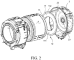
FIG.2 is an exploded diagram of some components of the clothes drying appliance; -
FIG. 3 is a front view of a heat exchange device; and -
FIG. 4 is a schematic diagram of components of the heat exchange device as shown inFIG. 3 . - As shown in
FIG. 1 , aclothes drying appliance 1 includes atub 2 forming a main drying chamber and arotatable drum 4 located in thetub 2 and driven by amotor 3. Awall 41 of thedrum 4 includes densely distributedholes 42, so that air is circulated between the inside of thedrum 4 and thetub 2. Arear wall 43 of the drum is connected to adrive shaft 44 for driving the drum to rotate. Thedrive shaft 44 passes through abearing 23 on arear wall 22 of the tub to be in transmission connection to themotor 3. Thedrum 4 is horizontally disposed. In another implementation, the drum may alternatively be disposed in an inclined manner in an inclined tub. The above "horizontal" and "inclined" are based on a horizontal or inclined central shaft of thedrum 4 as a reference object. - The
tub 2 is connected to aprocess air channel 5. Anair inlet 51 of theprocess air channel 5 is connected to aside wall 21 of thetub 2, and close to therear wall 22 of thetub 2. Anair outlet 52 of theprocess air channel 5 is connected to agasket 6 installed in a front side of thetub 2. Therefore, theprocess air channel 5 is in communication with thetub 2. In another implementation, the inlet of theprocess air channel 5 may alternatively be connected to therear wall 22 of thetub 2. - The
process air channel 5 includes afan 7 and aheating device 8. After thefan 7 is started, air may be blown to enter theprocess air channel 5 from theair inlet 51 of theprocess air channel 5, blown out through theair outlet 52 after passing through theheating device 8, to enter the front side of thetub 2. The air enters thedrum 4 to be fully in contact with clothes, and then passes through theholes 42 on thewall 41 of the drum. More air flow passes through theholes 42 to enter agap 9 that has a lower pressure and that is formed between therear wall 22 of the tub and therear wall 43 of the drum, then concentrates at theair inlet 51 of theprocess air channel 5 along thegap 9, and finally enters theprocess air channel 5, to complete a circulation flow. - In this way, in the process of flowing to the
air inlet 51 of theprocess air channel 5, the process air densely passes through thegap 9 between therear wall 22 of the tub and therear wall 43 of the drum. Aheat exchange device 10 is disposed in thegap 9 between therear wall 22 of the tub and therear wall 43 of the drum. Therefore, the hot humid process air exchanges heat with theheat exchange device 10 when passing through thegap 9, the temperature is decreased and the moisture is condensed. Then the process air enters theprocess air channel 5 from theair inlet 51 under the effect of thefan 7. Afterwards, under the heating of theheating device 8, the temperature of the process air is increased again, and then the process air re-enters thetub 2 and thedrum 4 to be in contact with the clothes, to further evaporate the moisture in the clothes. - The
heat exchange device 10 is disposed between therear wall 22 of the tub and therear wall 43 of the drum where the process air densely passes through, thereby causing theheat exchange device 10 to work in higher heat exchange efficiency. In addition, because there is no need to dispose a dedicated heat exchange channel, more space is saved, thereby reducing the volume and manufacturing costs of theclothes drying appliance 1. - The
heat exchange device 10 is in a flat structure, and is fixed on thetub 2, for example, may be fixed on therear wall 22 of the tub. Theheat exchange device 10 includes afluid channel 11 defined by a material with better thermal conductivity. Thefluid channel 11 includes awall 20 penetrating through thetub 2, for example, aninlet 12 of therear wall 22. Anoutlet 13 of thefluid channel 11 is located in thetub 2. In a working process, a cooling medium is supplied to thefluid channel 11 from theinlet 12 of thefluid channel 11. The cooling medium exchanges heat with the process air in contact with theheat exchange device 10 through a heat-conducting channel wall, to reduce the temperature of the process air. The cooling medium with an increased temperature is drained from the bottom of thetub 2. The cooling medium may be water. Thefluid channel 11 may supply continuous cooling medium to theheat exchange device 10, and the cooling medium may flow in thefluid channel 11, to fully exchange heat with the process air through the channel wall, to make full use of the cooling medium. In this case, because the cooling medium is flowing in thefluid channel 11, no splashing occurs under the blowing of the air flow, no cooling medium enters thedrum 4 to wet the clothes, and no cooling medium is inhaled to theprocess air channel 5 by thefan 7. In addition, theheat exchange device 10 in a flat structure and including thefluid channel 11 may be designed to have a thinner thickness according to a need, so that a requirement for a width of thegap 9 between therear wall 22 and therear wall 43 of the drum is not high, allowing the air to easily pass through the gap. - In the embodiment shown in
FIG. 2 , theheat exchange device 10 includes aflat body 14. Thebody 14 is basically in a ring structure, including a round throughhole 15. Thebody 14 is fixed on therear wall 22 of thetub 2 in various feasible fixing manners, for example, welding, pasting, screw fixing or injection molding. Thebody 14 is coaxial with the bearing 23 on therear wall 22 of thetub 2, and therefore is basically coaxially disposed with thedrum 4. Thedrive shaft 44 passes through the throughhole 15 of theheat exchange device 10. Theheat exchange device 10 is disposed in such a way to extend to fully make use of the size of therear wall 22 of the tub, thereby making a heat exchange area as large as possible, and improving the heat exchange efficiency. In this way, installations of thetub 2, thedrum 4 and a drive system are not affected. More favorably, the hot humid process air is prone to close to therear wall 22 of the tub along the edge of thetub 2 and thedrum 4, so that the design of the throughhole 15 can enable thefluid channel 11 to be more concentrated in areas where the process air is more concentrated. - As shown in
FIG. 3 and FIG. 4 , thebody 14 of theheat exchange device 10 includes a flatly distributedfluid channel 11. The fluid channel includes theinlet 12 and theoutlet 13, suitable for receiving the cooling medium to enter thefluid channel 11 from theinlet 12, and for the cooling medium to leave thefluid channel 11 from theoutlet 13. - The
body 14 includes afirst sheet 141 and asecond sheet 142 that are respectively made of metals and that are basically in a ring shape. Thefirst sheet 141 is substantially flat. Thesecond sheet 142 includes apre-formed recess 16. Thefirst sheet 141 and thesecond sheet 142 are attached and fixed to each other, to form abody 14 that is roughly in a ring shape. In addition, thefluid channel 11 is formed in the space surrounded by therecess 16 and thefirst sheet 141. Thefirst sheet 141 and thesecond sheet 142 are made of other materials with better thermal conductivity, or materials at least not inferior to common metals. - After the
inlet 12, thefluid channel 11 is divided into two paths, respectively located at two sides of the throughhole 15, and respectively having anoutlet 13 at the end. The cooling medium entering thefluid channel 11 from theinlet 12 is respectively left at the two sides of the throughhole 15, to fill theentire fluid channel 11, while evenly exchanging heat with the process air of the two sides of the throughhole 15. - In the embodiment shown in
FIG. 3 and FIG. 4 , thefluid channel 11 is folded and bent, andsegments 110 bent with each other are parallel to each other. - In another embodiment not shown in the accompanying drawings, it may be implemented that an acute angle is formed between every two adjacent bent segments. After the heat exchange device is installed on the rear wall of the tub, according to the disposing manners of the tub and the drum, the flat body is installed in a vertical or an inclined manner relative to a horizontal plane, and the inlet of the fluid channel is higher than other parts of the fluid channel. In this case, along a fluid flowing direction, at least some of the segments of the fluid channel are inclined downwards relative to the horizontal plane. Usually, the cooling medium is tap water. The cooling water can generate larger potential energy in an inclined bent area, and generate larger turbulence in the bent segments, thereby reducing accumulation of sediments in the water at the bent segments, so that the water flow is more smooth in the fluid channel, to prevent the fluid channel from congestion.
- As shown in
FIG. 2 andFIG. 4 , theheat exchange device 10 is installed in a way in which thefirst sheet 141 in a smooth structure faces the rear wall of the drum, and thesecond sheet 142 having apre-formed recess 16 faces the rear wall of the tub. Thesecond sheet 142 is fixed on therear wall 22 of the tub. Thefirst sheet 141 and thesecond sheet 142 respectively form a first wall and a second wall at two sides of thebody 14. - The various specific implementations described above and shown in the accompanying drawings are only used to describe the present invention. In the scope of the basic technical idea of the present invention, any form of modification made to the present invention by a person of ordinary skill in a related technical field shall fall within the protection scope of the present invention.
Claims (8)
- A clothes drying appliance, comprising a drum disposed in a horizontal or an inclined manner, rotatably located in a tub, wherein a wall of the drum comprises a plurality of densely distributed holes, allowing process air engaged in drying to circulate between the drum and the tub, a rear wall of the drum is connected to a drive shaft for driving the drum to rotate, and the drive shaft passes through a bearing on a rear wall of the tub, characterized in that: the tub is connected to a process air channel, a fan is disposed in the process air channel, an inlet of the process air channel is located on the rear wall of the tub or close to the rear wall of the tub, a heat exchange device is disposed between the rear wall of the tub and the rear wall of the drum, the heat exchange device comprises a flat body, the body comprises a flatly distributed fluid channel, and the fluid channel comprises an outlet and an inlet, suitable for receiving a cooling medium to enter the fluid channel from the inlet, and for the cooling medium to leave the fluid channel from the outlet, wherein at least part of the body is made of a metal or a material with no less thermal conductivity than a metal.
- The clothes drying appliance according to claim 1, characterized in that: the body comprises a through hole, the fluid channel is distributed around the through hole, and the drive shaft passes through the through hole of the heat exchange device.
- The clothes drying appliance according to claim 2, characterized in that: two sides of the through hole respectively comprise at least one fluid channel.
- The clothes drying appliance according to claim 1, characterized in that: the body comprises a first wall facing the rear wall of the drum and a second wall facing the rear wall of the tub, wherein the first wall is in a smooth structure and the second wall is fixed on the rear wall of the tub.
- The clothes drying appliance according to claim 4, characterized in that: the first wall is made of a metal or a material with no less thermal conductivity than a metal.
- The clothes drying appliance according to claim 1, characterized in that: the fluid channel is folded and bent, forming an acute angle between every two adjacent bent segments.
- The clothes drying appliance according to claim 1, characterized in that: the fluid channel is folded and bent, and segments bent with each other are parallel to each other.
- The clothes drying appliance according to claim 1, characterized in that: the fluid channel is folded and bent, comprising a plurality of segments bent with each other, and along a fluid flowing direction, at least some of the segments of the fluid channel are inclined downwards relative to a horizontal plane.
Applications Claiming Priority (1)
| Application Number | Priority Date | Filing Date | Title |
|---|---|---|---|
| CN201811451051.0A CN111254668A (en) | 2018-11-30 | 2018-11-30 | Clothes drying appliance |
Publications (1)
| Publication Number | Publication Date |
|---|---|
| EP3660193A1 true EP3660193A1 (en) | 2020-06-03 |
Family
ID=68501426
Family Applications (1)
| Application Number | Title | Priority Date | Filing Date |
|---|---|---|---|
| EP19207993.7A Ceased EP3660193A1 (en) | 2018-11-30 | 2019-11-08 | Clothes drying appliance |
Country Status (2)
| Country | Link |
|---|---|
| EP (1) | EP3660193A1 (en) |
| CN (1) | CN111254668A (en) |
Families Citing this family (2)
| Publication number | Priority date | Publication date | Assignee | Title |
|---|---|---|---|---|
| CN117966447B (en) * | 2023-12-21 | 2025-10-28 | 珠海格力电器股份有限公司 | Drying device, method and clothing processing equipment |
| CN118007369B (en) * | 2024-02-04 | 2025-09-23 | 珠海格力电器股份有限公司 | Clothes processing device with drying function and control method |
Citations (7)
| Publication number | Priority date | Publication date | Assignee | Title |
|---|---|---|---|---|
| DE1808534A1 (en) * | 1968-11-08 | 1970-06-11 | Siemens Elektrogenaete Gmbh | Washing machine for washing, spinning and drying the laundry |
| US3922798A (en) * | 1974-08-19 | 1975-12-02 | Gen Electric | Clothes dryer |
| US6279357B1 (en) | 1998-06-18 | 2001-08-28 | General Domestic Appliances Limited | Washer dryer |
| CN105200748A (en) * | 2015-09-01 | 2015-12-30 | 无锡小天鹅股份有限公司 | Clothes dryer |
| CN105463804A (en) | 2014-07-15 | 2016-04-06 | 博西华电器(江苏)有限公司 | Clothes dryer |
| US20180094376A1 (en) * | 2016-10-05 | 2018-04-05 | Samsung Electronics Co., Ltd. | Washing and drying machine |
| EP3330432A1 (en) * | 2016-11-30 | 2018-06-06 | BSH Hausgeräte GmbH | Laundry drying machine |
Family Cites Families (5)
| Publication number | Priority date | Publication date | Assignee | Title |
|---|---|---|---|---|
| DE602007009374D1 (en) * | 2007-07-26 | 2010-11-04 | Candy Spa | clothes dryer |
| CN201770878U (en) * | 2010-06-30 | 2011-03-23 | 博西华电器(江苏)有限公司 | Clothes dryer |
| CN104711833B (en) * | 2013-12-13 | 2018-04-06 | 博西华电器(江苏)有限公司 | Dryer |
| CN105200747A (en) * | 2014-06-10 | 2015-12-30 | 博西华电器(江苏)有限公司 | Clothes dryer |
| CN106894210B (en) * | 2015-12-17 | 2020-07-10 | 博西华电器(江苏)有限公司 | clothes dryer |
-
2018
- 2018-11-30 CN CN201811451051.0A patent/CN111254668A/en active Pending
-
2019
- 2019-11-08 EP EP19207993.7A patent/EP3660193A1/en not_active Ceased
Patent Citations (7)
| Publication number | Priority date | Publication date | Assignee | Title |
|---|---|---|---|---|
| DE1808534A1 (en) * | 1968-11-08 | 1970-06-11 | Siemens Elektrogenaete Gmbh | Washing machine for washing, spinning and drying the laundry |
| US3922798A (en) * | 1974-08-19 | 1975-12-02 | Gen Electric | Clothes dryer |
| US6279357B1 (en) | 1998-06-18 | 2001-08-28 | General Domestic Appliances Limited | Washer dryer |
| CN105463804A (en) | 2014-07-15 | 2016-04-06 | 博西华电器(江苏)有限公司 | Clothes dryer |
| CN105200748A (en) * | 2015-09-01 | 2015-12-30 | 无锡小天鹅股份有限公司 | Clothes dryer |
| US20180094376A1 (en) * | 2016-10-05 | 2018-04-05 | Samsung Electronics Co., Ltd. | Washing and drying machine |
| EP3330432A1 (en) * | 2016-11-30 | 2018-06-06 | BSH Hausgeräte GmbH | Laundry drying machine |
Also Published As
| Publication number | Publication date |
|---|---|
| CN111254668A (en) | 2020-06-09 |
Similar Documents
| Publication | Publication Date | Title |
|---|---|---|
| US11214907B2 (en) | Combined washing and drying machine | |
| US20140250710A1 (en) | Laundry treating apparatus | |
| EP1992730A1 (en) | Washing machine with steam generator | |
| CN105463812A (en) | Washing and drying integrated machine | |
| EP3330432B1 (en) | Laundry drying machine | |
| EP2955264A1 (en) | Clothes dryer | |
| CN104711833A (en) | Clothes drying machine | |
| CN103015140A (en) | Clothes dryer | |
| EP3660193A1 (en) | Clothes drying appliance | |
| CN206346058U (en) | For the condenser of clothes treatment device and the clothes treatment device with it | |
| CN109371627A (en) | A drum type washing and drying machine | |
| CN204803583U (en) | Clothe nursing machine | |
| CN100503954C (en) | Drum washing machine with drying function | |
| EP3660194B1 (en) | Heat exchange apparatus and laundry drying appliance having heat exchange apparatus | |
| CN220520919U (en) | Heat pump system and heat pump washing and drying integrated machine | |
| CN108729168B (en) | Clothes dryer | |
| CN111254672B (en) | Heat exchange device and clothes drying appliance with heat exchange device | |
| CN116043474A (en) | Clothes treatment device | |
| CN114250608B (en) | Heat exchange component in clothing care device and clothing drying device | |
| EP3224403B1 (en) | A clothes dryer | |
| CN114250609B (en) | Water-gas mixed heat exchange component and clothes drying device | |
| EP3660204A1 (en) | Laundry drying appliance | |
| CN203247438U (en) | Clothes dryer | |
| CN202989623U (en) | Condensed water circulating type energy-saving dryer | |
| CN105133273A (en) | Washing machine with heat exchanger |
Legal Events
| Date | Code | Title | Description |
|---|---|---|---|
| PUAI | Public reference made under article 153(3) epc to a published international application that has entered the european phase |
Free format text: ORIGINAL CODE: 0009012 |
|
| STAA | Information on the status of an ep patent application or granted ep patent |
Free format text: STATUS: THE APPLICATION HAS BEEN PUBLISHED |
|
| AK | Designated contracting states |
Kind code of ref document: A1 Designated state(s): AL AT BE BG CH CY CZ DE DK EE ES FI FR GB GR HR HU IE IS IT LI LT LU LV MC MK MT NL NO PL PT RO RS SE SI SK SM TR |
|
| AX | Request for extension of the european patent |
Extension state: BA ME |
|
| STAA | Information on the status of an ep patent application or granted ep patent |
Free format text: STATUS: REQUEST FOR EXAMINATION WAS MADE |
|
| 17P | Request for examination filed |
Effective date: 20201203 |
|
| RBV | Designated contracting states (corrected) |
Designated state(s): AL AT BE BG CH CY CZ DE DK EE ES FI FR GB GR HR HU IE IS IT LI LT LU LV MC MK MT NL NO PL PT RO RS SE SI SK SM TR |
|
| STAA | Information on the status of an ep patent application or granted ep patent |
Free format text: STATUS: EXAMINATION IS IN PROGRESS |
|
| 17Q | First examination report despatched |
Effective date: 20220620 |
|
| STAA | Information on the status of an ep patent application or granted ep patent |
Free format text: STATUS: THE APPLICATION HAS BEEN REFUSED |
|
| 18R | Application refused |
Effective date: 20250425 |