EP3224403B1 - A clothes dryer - Google Patents
A clothes dryer Download PDFInfo
- Publication number
- EP3224403B1 EP3224403B1 EP15797111.0A EP15797111A EP3224403B1 EP 3224403 B1 EP3224403 B1 EP 3224403B1 EP 15797111 A EP15797111 A EP 15797111A EP 3224403 B1 EP3224403 B1 EP 3224403B1
- Authority
- EP
- European Patent Office
- Prior art keywords
- air
- heat exchanger
- manifold
- fan
- clothes dryer
- Prior art date
- Legal status (The legal status is an assumption and is not a legal conclusion. Google has not performed a legal analysis and makes no representation as to the accuracy of the status listed.)
- Active
Links
- 239000003570 air Substances 0.000 claims description 146
- XLYOFNOQVPJJNP-UHFFFAOYSA-N water Substances O XLYOFNOQVPJJNP-UHFFFAOYSA-N 0.000 claims description 21
- 238000001035 drying Methods 0.000 claims description 10
- 230000007246 mechanism Effects 0.000 claims description 9
- 239000012080 ambient air Substances 0.000 claims description 4
- 230000000903 blocking effect Effects 0.000 claims description 3
- 238000001816 cooling Methods 0.000 claims description 3
- 239000007788 liquid Substances 0.000 claims description 3
- 230000008878 coupling Effects 0.000 claims description 2
- 238000010168 coupling process Methods 0.000 claims description 2
- 238000005859 coupling reaction Methods 0.000 claims description 2
- 238000005086 pumping Methods 0.000 claims description 2
- 238000010438 heat treatment Methods 0.000 description 15
- RYGMFSIKBFXOCR-UHFFFAOYSA-N Copper Chemical compound [Cu] RYGMFSIKBFXOCR-UHFFFAOYSA-N 0.000 description 5
- 239000010949 copper Substances 0.000 description 5
- 229910052802 copper Inorganic materials 0.000 description 5
- 238000002156 mixing Methods 0.000 description 4
- 238000012546 transfer Methods 0.000 description 4
- 239000004411 aluminium Substances 0.000 description 3
- XAGFODPZIPBFFR-UHFFFAOYSA-N aluminium Chemical compound [Al] XAGFODPZIPBFFR-UHFFFAOYSA-N 0.000 description 3
- 229910052782 aluminium Inorganic materials 0.000 description 3
- 230000000694 effects Effects 0.000 description 3
- 238000004519 manufacturing process Methods 0.000 description 3
- 238000012360 testing method Methods 0.000 description 3
- 230000008901 benefit Effects 0.000 description 2
- 230000008859 change Effects 0.000 description 2
- 238000004140 cleaning Methods 0.000 description 2
- 238000010276 construction Methods 0.000 description 2
- 238000000151 deposition Methods 0.000 description 2
- 238000009826 distribution Methods 0.000 description 2
- 238000000034 method Methods 0.000 description 2
- 230000008569 process Effects 0.000 description 2
- 241000772991 Aira Species 0.000 description 1
- 229910000831 Steel Inorganic materials 0.000 description 1
- 230000009471 action Effects 0.000 description 1
- 238000013459 approach Methods 0.000 description 1
- 230000033228 biological regulation Effects 0.000 description 1
- 238000007664 blowing Methods 0.000 description 1
- 238000009833 condensation Methods 0.000 description 1
- 230000005494 condensation Effects 0.000 description 1
- 239000000356 contaminant Substances 0.000 description 1
- 238000013461 design Methods 0.000 description 1
- 230000009977 dual effect Effects 0.000 description 1
- 239000000428 dust Substances 0.000 description 1
- 238000005516 engineering process Methods 0.000 description 1
- 230000020169 heat generation Effects 0.000 description 1
- 238000012423 maintenance Methods 0.000 description 1
- 239000010959 steel Substances 0.000 description 1
Images


Classifications
-
- D—TEXTILES; PAPER
- D06—TREATMENT OF TEXTILES OR THE LIKE; LAUNDERING; FLEXIBLE MATERIALS NOT OTHERWISE PROVIDED FOR
- D06F—LAUNDERING, DRYING, IRONING, PRESSING OR FOLDING TEXTILE ARTICLES
- D06F58/00—Domestic laundry dryers
- D06F58/20—General details of domestic laundry dryers
-
- D—TEXTILES; PAPER
- D06—TREATMENT OF TEXTILES OR THE LIKE; LAUNDERING; FLEXIBLE MATERIALS NOT OTHERWISE PROVIDED FOR
- D06F—LAUNDERING, DRYING, IRONING, PRESSING OR FOLDING TEXTILE ARTICLES
- D06F2105/00—Systems or parameters controlled or affected by the control systems of washing machines, washer-dryers or laundry dryers
- D06F2105/28—Electric heating
-
- D—TEXTILES; PAPER
- D06—TREATMENT OF TEXTILES OR THE LIKE; LAUNDERING; FLEXIBLE MATERIALS NOT OTHERWISE PROVIDED FOR
- D06F—LAUNDERING, DRYING, IRONING, PRESSING OR FOLDING TEXTILE ARTICLES
- D06F58/00—Domestic laundry dryers
- D06F58/02—Domestic laundry dryers having dryer drums rotating about a horizontal axis
-
- D—TEXTILES; PAPER
- D06—TREATMENT OF TEXTILES OR THE LIKE; LAUNDERING; FLEXIBLE MATERIALS NOT OTHERWISE PROVIDED FOR
- D06F—LAUNDERING, DRYING, IRONING, PRESSING OR FOLDING TEXTILE ARTICLES
- D06F58/00—Domestic laundry dryers
- D06F58/10—Drying cabinets or drying chambers having heating or ventilating means
-
- D—TEXTILES; PAPER
- D06—TREATMENT OF TEXTILES OR THE LIKE; LAUNDERING; FLEXIBLE MATERIALS NOT OTHERWISE PROVIDED FOR
- D06F—LAUNDERING, DRYING, IRONING, PRESSING OR FOLDING TEXTILE ARTICLES
- D06F58/00—Domestic laundry dryers
- D06F58/20—General details of domestic laundry dryers
- D06F58/26—Heating arrangements, e.g. gas heating equipment
Definitions
- the invention relates to clothes dryers.
- the clothes dryers available on the market are mainly of the tumble dryer type. Air is drawn in by a fan and is blown across an electrical heating element and into a drum. The air flow into the drum is typically via an array of holes in a plate at the back of the drum.
- the invention is directed towards providing an improved clothes dryer with less energy input and cost. Another objective is to minimise changes to the shape and configuration and parts of typical "standard" dryers - for ease of manufacture, maintenance, and fitting into available spaces.
- Irish Patent No. S86294 describes a dryer which uses heat energy from a water heating system, and so reduces electrical power consumption. However it involves considerable change in the arrangement of the standard known dryer, and is complex.
- US6941680 describes a dryer which is linked to a heating system. An assembly of a fan, a filter, and a heat exchanger is mounted on the back of the unit, and the fan blows air through the heat exchanger and into a drum.
- EP0430197 also describes use of a connection to the hot water system of a household for a tumble dryer.
- the invention addresses this problem.
- the heat exchanger may be supplied with heat energy from a building's central heating system, or external heat generation units including district heating systems.
- the air fan is arranged to pull air through the heat exchanger.
- the air fan is a centrifugal fan having curved blades with convex surfaces facing in a direction or rotation.
- the air fan is arranged to axially pull air through the heat exchanger and into an internal volume of said air fan.
- the air fan is in a manifold mounted adjacent the heat exchanger and is arranged to pull air through the heat exchanger and into the manifold through a manifold inlet in said first pass, and to blow heated air through a manifold outlet and into the heat exchanger in said further pass.
- the air fan and the manifold are arranged to draw ambient air through a portion of the heat exchanger and into the manifold, and blow said air back into a different portion of the heat exchanger.
- said portions are spaced apart in a lateral dimension across the dryer.
- the air fan and the heat exchanger are arranged to provide sufficient air pressure to cause air in said further pass to spread through at least part of the heat exchanger before exiting at an upper heat exchanger outlet.
- the air fan is a centrifugal fan mounted to draw said first pass air axially into a volume of the fan, and to blow it laterally within the manifold with sufficient pressure to exhaust the manifold and enter the heat exchanger in said further pass.
- said manifold inlet has a larger cross-sectional area than said manifold outlet.
- the manifold outlet has a cross-sectional area in the range of 25% to 90% of the cross-sectional area of the manifold inlet.
- the air fan and the heat exchanger are arranged to allow some first pass air to mix with further pass air.
- the dryer comprises a diverter for diverting further pass air across the heat exchanger and into a path of said first pass air.
- the diverter comprises a plate bordering or spaced apart from the heat exchanger. In one embodiment, the plate is normal to a direction of said further pass air flow through the heat exchanger.
- the heat exchanger comprises elongate parallel elements
- the diverter is spaced apart from said elongate parallel elements to define a volume within which said second pass air can flow alongside and perpendicular to said elongate parallel elements until it is drawn into volumes between said elongate parallel elements by said first pass air.
- the diverter is located on a side of the heat exchanger opposed to the fan.
- the diverter includes an aperture for flow of first pass air into the heat exchanger.
- the heater includes an electrical element, and the controller is configured to operate the electric element if heat is not available to the heat exchanger.
- the electric element is in a drum air inlet manifold of said drum hot air inlet.
- the heat exchanger is below and operatively connected to the drum inlet manifold.
- the heat exchanger comprises heat exchange tubes extending through fins.
- the fins are arranged in a direction aligned with the drum hot air inlet.
- the air fan is arranged to be driven by the drum drive mechanism. In one embodiment, the air fan is on an outlet shaft of a motor of said drum drive mechanism.
- the dryer further comprises a valve for blocking flow of hot water to the heat exchanger for part of a drying cycle.
- the controller is arranged to control operation of said valve, for a phase of operation such as a cooling down period.
- a clothes dryer comprising a controller, a housing, a drum, a drum drive mechanism, a drum hot air inlet, and an air fan for pumping air through a heater en route to the drum hot air inlet, wherein the heater includes a heat exchanger having a coupling for connection to a supply of hot water or other liquid.
- the housing has the general configuration of a conventional clothes dryer.
- the heater includes an electrical element, and the controller is configured to operate the element if heat is not available to the heat exchanger.
- the element is in a drum inlet manifold. In one embodiment, in the heat exchanger is below the drum inlet manifold.
- the fan is arranged to draw air in through the heat exchanger. In one embodiment, the fan is in a manifold arranged to direct air in back into the heat exchanger. In one embodiment, the heat exchanger is arranged to allow some pumped air to mix with inlet air so that it is re-circulated through the heat exchanger. In one embodiment, the dryer comprises a diverter for diverting air which has been pumped back into the heat exchanger in a further pass back into the heat exchanger. In one embodiment, the diverter comprises a plate bordering or spaced apart from the heat exchanger. Preferably, the plate is normal to a direction of air flow through the heat exchanger.
- the heat exchanger is of the plate type.
- the fan and the manifold are arranged to:
- the fan is arranged to be driven by the drum drive mechanism. In one embodiment, the fan is on an outlet shaft of a motor of said drum drive mechanism.
- the dryer further comprises a valve for blocking flow of hot water to the heat exchanger for part of a drying cycle.
- the controller is arranged to control operation of said valve, for a phase of operation such as a cooling down period.
- the fan and the heat exchanger are arranged for contra-flow to prevent dust or other contaminant build-up on heat exchange elements.
- a domestic tumble dryer 1 of the invention comprises a rectangular box housing 2. It is similar in overall configuration to a conventional, under-counter, tumble dryer. At its back it has a panel 3 with an air inlet 4, an outlet 5, and a vent 6.
- the dryer 2 has a drum 10 of the conventional type, driven in a conventional manner by a motor 11 via a belt 12.
- a heat exchange assembly comprising a tube and fin heat exchanger 20 with a hot water inlet 20(a) and a cool water outlet 20(b) for linking with a building's heating system.
- the heat exchanger comprises vertically arranged fins 20(c) through which horizontal tubes run in a zig-zag pattern from the inlet 20(a) to the outlet 20(b).
- the drum air inlet manifold 23 is shallow, and round in shape when viewed from the rear, being similar in overall configuration to the inlet manifold of a conventional dryer which uses an electric element for heating the air as it passes through the manifold.
- the drum air inlet manifold manifold 23 includes an electrical coil element 24 in a flow path axially into the drum 10 via apertures in the back plate of the drum 10.
- the drum aperture arrangement to take in hot air is conventional.
- the heat exchanger manifold 21 includes a centrifugal fan 25 around a manifold inlet 26 which is in-line with the overall machine's inlet 4.
- the manifold 21 also has an exhaust outlet 27 parallel to the inlet 26 and laterally spaced apart from it.
- the outlet 27 is arranged to blow air back into the heat exchanger 20 at a location offset from the manifold inlet 26.
- the inlet 26 has a cross-sectional area of about 120 cm 2
- the outlet 27 has a cross-sectional area of about 60 cm 2 .
- the area of the manifold outlet be greater than that of the manifold inlet, as this causes a faster flow velocity for the same overall flow rate, thereby assisting distribution of second pass air into and across the heat exchanger as described in more detail below.
- the outlet has a cross-sectional area which is preferably in the range of 25% to 90% that of the inlet.
- the fan 25 in the manifold 21 is driven by the motor 11 and so does not require a drive additional to that which is provided in a typical tumble dryer.
- the controller is preferably of a conventional type in hardware terms, being programmed to operate the components according to user instructions especially in terms of temperatures and times.
- the instructions will have a bearing on the fan speeds, and possible control of a solenoid valve for heat exchanger supply.
- the control panel (not shown) is operated to select heat energy from the heating system instead of the element 24 if such hot water is available.
- the fan 25 draws air from outside through the inlet 4 and the heat exchanger 20 in a first pass. This air is heated as it passes through the heat exchanger 20. The air is then blown laterally in the manifold 21 by the fan 25.
- the fan 25 is of the centrifugal type, configured to efficiently draw air in axially and to pump it radially out.
- the pumped air is driven out through the manifold outlet 27 back into the heat exchanger 20 in a second pass.
- the heat exchanger has a back plate opposed to the manifold outlet 27, the pumped air is forced to spread laterally across the rear of the heat exchanger 20.
- the path for this in a narrow space between the plate 30 and the fins, but in other embodiments it may be may be through apertures in the (vertically-arranged) fins.
- the flow caused by the fan 25 and the configuration of the heat exchanger 20 and the plate 30 causes mixing of the air from the manifold 21 with fresh inlet air drawn through the machine inlet 4. This enhances the pre-heating effect. Hence the air entering the manifold 21 is already at an elevated temperature. This is best illustrated by the arrows in Fig. 4 .
- the air which is not re-circulated (approximately over 80% of it) is routed through the heat exchanger 20, picking up heat in the process, and exits the heat exchanger via the outlet 22 and progresses up into the drum manifold 23.
- This is a disc-shaped space from which the heated air enters the drum 10 via the drum's rear inlet apertures.
- the dryer 1 can operate using the conventional form of electric air heating using the coil 24 in the drum manifold 23.
- the machine's controller may also be configured to use this element at a lower setting if some heat is available from the heating system.
- the overall air flow path is the same whether heat is drawn from the heat exchanger 20 or from the electric element. This achieves simplicity of dryer construction, reliability, and compactness.
- the invention achieves much more economical clothes drying, by making use of heat which is available in a building's heating system. It may be easily coupled to the heating system in a manner akin to connecting a conventional radiator.
- the dryer has the major benefit of the heat exchanger and several of the components being self-cleaning because of the contra flow of air through the heat exchanger. This reduces or eliminates need for cleaning, and moreover reduces the fire hazard which might arise with build-up of fluff on hot parts. Indeed, in general there is reduced risk of fire because the components of the machine are at a lower temperature than with conventional machines using a heated electrical element as the only heat source. Moreover, even if the machine is used in the electrical element mode for a significant period of time there is still a reduced risk of fire by fluff depositing on the electrical element. This is because the air is pumped from a location just below the element and so there is a higher air pressure than is conventional with air being drawn by a fan downstream of the drum.
- the machine does not take up any more space than a conventional machine, and it allows drying even when heat is not available from the heating system.
- valve at the heat exchanger inlet to temporarily block flow of hot water for certain phases of use of the machine 1.
- the hot water flow may be blocked during a final phase of say 10 minutes to allow the clothes to cool down and prevent creasing.
- the dryer may be of the condenser type, using the existing technology for condensing.
- the depth of this gap may be chosen to set a desired level of air turbulence and re-circulation.
- the gap may be adjustable after manufacture to achieve the desired effect.
- There may be different arrangements of heat exchangers and/or valves for diversion of air to control the extent of re-circulation.
- the dryer 100 has an outer casing 102 with a back panel 104 having a grille.
- a drum manifold 110 which is dish-shaped as is conventional. However it has a cut-out in the lower side to receive an electrical heater 111.
- a plate 115 is fitted against the fan / manifold assembly 25/21, having apertures 116 and 117 aligned with the manifold 26 and the manifold outlet 27.
- a rectangular heat exchanger 120 is placed against the plate 115 it is in line with the electrical heater 111 and the interior of the drum manifold 110.
- the heat exchanger 120 has water inlet and outlet couplers 121 and 122 respectively.
- a drive shaft (not shown) from the motor 11 drives the belt 12 and the fan 25, as in the above embodiment.
- the heat exchanger 120 has copper tubes and aluminium fins.
- the copper pipes are mechanically crimped in the fins, and these are provided with small collars which increase the surface of exchange between each other.
- the fins have an aluminium surface slightly waved to improve the quality of the thermic exchange by effect of turbulence. This characteristic does not modify significantly the pressure drop created on the air.
- the standard space between the fins is of 2.1 mm.
- the heat exchanger may have an "AIRA" air curtain design fitted in order to provide additional regulation to air flow.
- the tubes are made of copper reels of 10mm tubes directly formed to dimension. After the expansion process in the fin the internal surface is smooth to reduce water pressure drop.
- the frames are of galvanised steel, to ensure rigidity of the set and protect the copper and the aluminium from contact with sharp elements. It allows the mounting of the exchanger on gliders.
- the collectors are made of copper, arranged to collect the parallel circuits of the heat exchanger and gather them into one single main circuit.
- the distributor/capillaries are welded to allow a well balanced distribution of the liquid in the parallel circuits of the tube/coils.
- inlet air 140 flows into the heat exchanger 120, through the gaps between the heat exchanger fins 124 (through which tubes 123 extend).
- the fins 124 are vertically aligned and so flow 140 can continue through the heat exchanger 120 and into the fan/manifold assembly 25/21 as a first pass flow 141.
- the fan 25 has blades 150 curved with a convex surface facing in the (clockwise, as viewed from the heat exchanger) direction of travel.
- the fan 25 delivers air in a lateral flow 142 across the manifold 21 and from there it flows in a second pass 143 back into the heat exchanger 120. Due to a gap 130 between the panel 104 and the fins 124 some air flows (144) laterally across the back of the heat exchanger.
- the following is a set of test data for performance of the dryer 100.
- the air flow rate was up to 16m 3 /h.
- a 55 minute wash with a 1400rpm spin cycle was utilised to wash clothes to ensure clothes were prepared for each drying test cycle and presented in similar conditions and identical weights.
- the air speed into the heat exchanger at the inlet 116 for the above was 12 m/s, and the speed out of the manifold outlet 117 was 18 m/s.
- an alternative heat exchange assembly for a dryer of the invention has parts similar to the above embodiments indicated by the same reference numerals.
- this case there is a plate 160 behind and in contact with the rear of the heat exchanger 120. This completely seals off the rear of the heat exchanger in the sense of preventing lateral flow across.
- Second pass air can travel across ((171) to be drawn into the first pass air 165/166.
- a condenser dryer embodiment has a heat exchange assembly 200, and again like parts are given the same reference numerals.
- a condenser tubular section 203 and a fan 205 for drawing in cool air to cause condensation into a water trap 206.
- a heat exchanger does not reduce flexibility in dryer configuration, both air exhaust and condenser types can be readily provided.
- the dryer of the various embodiments has the major benefit of achieving exceptional energy efficiency by using heat which is available anyway in most buildings, but at the same time requiring little configuration and size difference from the known electric-only dryers.
- the fan (25) is arranged to pull air through the heat exchanger it is particularly efficient to direct it in a manner to optimise heat transfer with the multiple passes, possible involving mixing.
- Use of a centrifugal fan having curved blades with convex surfaces facing in a direction or rotation allows particularly effective drawing of air from space around the heat exchanger in the first pass and then to change direction for the second pass, of in embodiments with only one pass, for onward flow to the drum. If there is only one pass, it is preferable that the heat exchanger be more aligned in the flow direction.
- the fan being arranged to direct air through the heat exchanger in a first pass and back into the heat exchanger in at least one further pass, provides particularly efficient heat transfer and compactness of the heat transfer assembly.
- the manifold mounted adjacent the heat exchanger also contributes significantly to compactness. It is a very advantageous way to draw ambient air through a portion of the heat exchanger and to blow the air back into a different portion of the heat exchanger. Because these portions are spaced apart in the lateral dimension (horizontal in use), the heat exchanger may be configured to be shallow but wide (approximately planar configuration), allowing it to fit in the housing in a compact manner.
- the manifold inlet has a larger cross-sectional area than the manifold outlet
- there is a higher flow rate in the second pass helping spread of the air across the heat exchanger and also upwardly to the drum.
- the manifold outlet has a cross-sectional area in the range of 30% to 80% of that of the inlet.
- a diverter such as a plate is a particularly effective and compact way of causing second pass air to spread across the heat exchanger and into the path of first pass air.
- the air can flow alongside and perpendicular to said elongate elements until it is drawn into volumes between said elongate elements by first pass air, and moreover it is directed towards the drum.
- the fins therefore influence both heat transfer and direction of air travel while guiding air towards the drum.
- the controller is configured to engage or energise the electrical element when no alternative heat source is available; this dual facility ultimately increases the versatility for the end user.
- recycled air flow acts as an effective cleanser of all components from flint/fluff due to the multidirectional travel of air-flow during all operations of this system.
- the dryer can be particularly compact and have few parts.
- the dryer may be of a capacity suitable for commercial use. It is preferable, but not essential, that air is drawn in through the heat exchanger for the electrical mode of operation.
- the air flow components draw air and pump it in an in-line axial manner through a heat exchanger without mixing.
- a heat exchanger may be in the form of baffles in an air flow duct.
- the heat exchanger may comprise an assembly of more than one physical unit mounted together.
Landscapes
- Engineering & Computer Science (AREA)
- Textile Engineering (AREA)
- Detail Structures Of Washing Machines And Dryers (AREA)
Description
- The invention relates to clothes dryers.
- At present the clothes dryers available on the market are mainly of the tumble dryer type. Air is drawn in by a fan and is blown across an electrical heating element and into a drum. The air flow into the drum is typically via an array of holes in a plate at the back of the drum.
- The invention is directed towards providing an improved clothes dryer with less energy input and cost. Another objective is to minimise changes to the shape and configuration and parts of typical "standard" dryers - for ease of manufacture, maintenance, and fitting into available spaces.
- Irish Patent No.
S86294 US6941680 describes a dryer which is linked to a heating system. An assembly of a fan, a filter, and a heat exchanger is mounted on the back of the unit, and the fan blows air through the heat exchanger and into a drum.EP0430197 also describes use of a connection to the hot water system of a household for a tumble dryer. - Despite knowledge of the principle of using heat supplied from a household hot water system since at least 1991 this principle has not been put to use in commercially available household products to the knowledge of the inventor. It appears that this is due to the complexity of the known approaches and non-conformance with well-established dryer sizes (such as under counter fitting) and/or achieving a machine which is simple enough to be reliable and have a low manufacturing cost.
- The invention addresses this problem.
- According to the invention there is provided a clothes dryer as set out in
claim 1. - The heat exchanger may be supplied with heat energy from a building's central heating system, or external heat generation units including district heating systems.
- In one embodiment, the air fan is arranged to pull air through the heat exchanger. In one embodiment, the air fan is a centrifugal fan having curved blades with convex surfaces facing in a direction or rotation. In one embodiment, the air fan is arranged to axially pull air through the heat exchanger and into an internal volume of said air fan.
- In one embodiment, the air fan is in a manifold mounted adjacent the heat exchanger and is arranged to pull air through the heat exchanger and into the manifold through a manifold inlet in said first pass, and to blow heated air through a manifold outlet and into the heat exchanger in said further pass.
- In one embodiment, the air fan and the manifold are arranged to draw ambient air through a portion of the heat exchanger and into the manifold, and blow said air back into a different portion of the heat exchanger. In one embodiment, said portions are spaced apart in a lateral dimension across the dryer.
- In one embodiment, the air fan and the heat exchanger are arranged to provide sufficient air pressure to cause air in said further pass to spread through at least part of the heat exchanger before exiting at an upper heat exchanger outlet.
- In one embodiment, the air fan is a centrifugal fan mounted to draw said first pass air axially into a volume of the fan, and to blow it laterally within the manifold with sufficient pressure to exhaust
the manifold and enter the heat exchanger in said further pass. In one embodiment, said manifold inlet has a larger cross-sectional area than said manifold outlet. In one embodiment, the manifold outlet has a cross-sectional area in the range of 25% to 90% of the cross-sectional area of the manifold inlet. - In one embodiment, the air fan and the heat exchanger are arranged to allow some first pass air to mix with further pass air. In one embodiment, the dryer comprises a diverter for diverting further pass air across the heat exchanger and into a path of said first pass air. Preferably, the diverter comprises a plate bordering or spaced apart from the heat exchanger. In one embodiment, the plate is normal to a direction of said further pass air flow through the heat exchanger.
- In one embodiment, the heat exchanger comprises elongate parallel elements, and the diverter is spaced apart from said elongate parallel elements to define a volume within which said second pass air can flow alongside and perpendicular to said elongate parallel elements until it is drawn into volumes between said elongate parallel elements by said first pass air. In one embodiment, the diverter is located on a side of the heat exchanger opposed to the fan.
- In one embodiment, the diverter includes an aperture for flow of first pass air into the heat exchanger.
- In one embodiment, the heater includes an electrical element, and the controller is configured to operate the electric element if heat is not available to the heat exchanger. In one embodiment, the electric element is in a drum air inlet manifold of said drum hot air inlet.
- In one embodiment, the heat exchanger is below and operatively connected to the drum inlet manifold. In one embodiment, the heat exchanger comprises heat exchange tubes extending through fins. In one embodiment, the fins are arranged in a direction aligned with the drum hot air inlet.
- In one embodiment, the air fan is arranged to be driven by the drum drive mechanism. In one embodiment, the air fan is on an outlet shaft of a motor of said drum drive mechanism.
- In one embodiment, the dryer further comprises a valve for blocking flow of hot water to the heat exchanger for part of a drying cycle. In one embodiment, the controller is arranged to control operation of said valve, for a phase of operation such as a cooling down period.
- According to the invention, there is provided a clothes dryer comprising a controller, a housing, a drum, a drum drive mechanism, a drum hot air inlet, and an air fan for pumping air through a heater en route to the drum hot air inlet, wherein the heater includes a heat exchanger having a coupling for connection to a supply of hot water or other liquid.
- In one embodiment, the housing has the general configuration of a conventional clothes dryer. In one embodiment, the heater includes an electrical element, and the controller is configured to operate the element if heat is not available to the heat exchanger. In one embodiment, the element is in a drum inlet manifold. In one embodiment, in the heat exchanger is below the drum inlet manifold.
- In one embodiment, the fan is arranged to draw air in through the heat exchanger. In one embodiment, the fan is in a manifold arranged to direct air in back into the heat exchanger. In one embodiment, the heat exchanger is arranged to allow some pumped air to mix with inlet air so that it is re-circulated through the heat exchanger. In one embodiment, the dryer comprises a diverter for diverting air which has been pumped back into the heat exchanger in a further pass back into the heat exchanger. In one embodiment, the diverter comprises a plate bordering or spaced apart from the heat exchanger. Preferably, the plate is normal to a direction of air flow through the heat exchanger.
- In one embodiment, the heat exchanger is of the plate type.
- In one embodiment, the fan and the manifold are arranged to:
- axially draw ambient air through a portion of the heat exchanger,
- pump air radially and direct it back into the heat exchanger at a location laterally spaced-apart from the inlet, and
- provide sufficient air pressure to cause it to spread through the heat exchanger before exiting at an upper heat exchanger outlet.
- In one embodiment, the fan is arranged to be driven by the drum drive mechanism. In one embodiment, the fan is on an outlet shaft of a motor of said drum drive mechanism.
- In one embodiment, the dryer further comprises a valve for blocking flow of hot water to the heat exchanger for part of a drying cycle. Preferably, the controller is arranged to control operation of said valve, for a phase of operation such as a cooling down period.
- In one embodiment, the fan and the heat exchanger are arranged for contra-flow to prevent dust or other contaminant build-up on heat exchange elements.
- The invention will be more clearly understood from the following description of some embodiments thereof, given by way of example only with reference to the accompanying drawings in which:-
-
Fig. 1 is a rear perspective view of a dryer of the invention; -
Fig. 2 is a perspective cut-away view showing the major internal parts for inlet air flow; -
Figs. 3 and 4 are further perspective cut-away views showing some of the parts more clearly; -
Fig. 5 is an exploded perspective view of the major air-handling parts of the dryer; -
Fig. 6 is a perspective view of an alternative dryer; -
Fig. 7 is a cut-away perspective of the dryer ofFig. 6 ; -
Fig. 8 is another cut-away perspective view, with the heat exchanger removed; -
Fig. 9 is an exploded view of this dryer; -
Figs. 10 and11 are plan and exploded perspective views showing the air flows of the dryer ofFigs. 6 to 9 in more detail; -
Fig. 12 is an exploded perspective view of an alternative heat exchange assembly for a dryer of the invention, and -
Fig. 13 is an exploded perspective view of the major air-handling parts of a further dryer of the invention, in this case a condenser dryer. - Referring to the drawings a
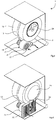
domestic tumble dryer 1 of the invention comprises arectangular box housing 2. It is similar in overall configuration to a conventional, under-counter, tumble dryer. At its back it has apanel 3 with an air inlet 4, anoutlet 5, and avent 6. - Internally, the
dryer 2 has adrum 10 of the conventional type, driven in a conventional manner by amotor 11 via abelt 12. - In addition, however, there is a heat exchange assembly comprising a tube and
fin heat exchanger 20 with a hot water inlet 20(a) and a cool water outlet 20(b) for linking with a building's heating system. The heat exchanger comprises vertically arranged fins 20(c) through which horizontal tubes run in a zig-zag pattern from the inlet 20(a) to the outlet 20(b). - There is a
heat exchanger manifold 21 on the internal side of theheat exchanger 20, and on the top side of the heat exchanger there is ahot air outlet 22 to a drumair inlet manifold 23. The drumair inlet manifold 23 is shallow, and round in shape when viewed from the rear, being similar in overall configuration to the inlet manifold of a conventional dryer which uses an electric element for heating the air as it passes through the manifold. The drum airinlet manifold manifold 23 includes anelectrical coil element 24 in a flow path axially into thedrum 10 via apertures in the back plate of thedrum 10. The drum aperture arrangement to take in hot air is conventional. - The
heat exchanger manifold 21 includes acentrifugal fan 25 around amanifold inlet 26 which is in-line with the overall machine's inlet 4. The manifold 21 also has anexhaust outlet 27 parallel to theinlet 26 and laterally spaced apart from it. Theoutlet 27 is arranged to blow air back into theheat exchanger 20 at a location offset from themanifold inlet 26. In this case theinlet 26 has a cross-sectional area of about 120 cm2, and theoutlet 27 has a cross-sectional area of about 60 cm2. It is preferable that the area of the manifold outlet be greater than that of the manifold inlet, as this causes a faster flow velocity for the same overall flow rate, thereby assisting distribution of second pass air into and across the heat exchanger as described in more detail below. In general the outlet has a cross-sectional area which is preferably in the range of 25% to 90% that of the inlet. - The
fan 25 in the manifold 21 is driven by themotor 11 and so does not require a drive additional to that which is provided in a typical tumble dryer. - The controller is preferably of a conventional type in hardware terms, being programmed to operate the components according to user instructions especially in terms of temperatures and times. The instructions will have a bearing on the fan speeds, and possible control of a solenoid valve for heat exchanger supply.
- In use, the control panel (not shown) is operated to select heat energy from the heating system instead of the
element 24 if such hot water is available. Thefan 25 draws air from outside through the inlet 4 and theheat exchanger 20 in a first pass. This air is heated as it passes through theheat exchanger 20. The air is then blown laterally in the manifold 21 by thefan 25. Thefan 25 is of the centrifugal type, configured to efficiently draw air in axially and to pump it radially out. The pumped air is driven out through themanifold outlet 27 back into theheat exchanger 20 in a second pass. As the heat exchanger has a back plate opposed to themanifold outlet 27, the pumped air is forced to spread laterally across the rear of theheat exchanger 20. The path for this in a narrow space between theplate 30 and the fins, but in other embodiments it may be may be through apertures in the (vertically-arranged) fins. - The flow caused by the
fan 25 and the configuration of theheat exchanger 20 and theplate 30 causes mixing of the air from the manifold 21 with fresh inlet air drawn through the machine inlet 4. This enhances the pre-heating effect. Hence the air entering the manifold 21 is already at an elevated temperature. This is best illustrated by the arrows inFig. 4 . - The air which is not re-circulated (approximately over 80% of it) is routed through the
heat exchanger 20, picking up heat in the process, and exits the heat exchanger via theoutlet 22 and progresses up into thedrum manifold 23. This is a disc-shaped space from which the heated air enters thedrum 10 via the drum's rear inlet apertures. - If there is no hot water available the
dryer 1 can operate using the conventional form of electric air heating using thecoil 24 in thedrum manifold 23. The machine's controller may also be configured to use this element at a lower setting if some heat is available from the heating system. - Advantageously, the overall air flow path is the same whether heat is drawn from the
heat exchanger 20 or from the electric element. This achieves simplicity of dryer construction, reliability, and compactness. - It will be appreciated that the invention achieves much more economical clothes drying, by making use of heat which is available in a building's heating system. It may be easily coupled to the heating system in a manner akin to connecting a conventional radiator.
- Also, the dryer has the major benefit of the heat exchanger and several of the components being self-cleaning because of the contra flow of air through the heat exchanger. This reduces or eliminates need for cleaning, and moreover reduces the fire hazard which might arise with build-up of fluff on hot parts. Indeed, in general there is reduced risk of fire because the components of the machine are at a lower temperature than with conventional machines using a heated electrical element as the only heat source. Moreover, even if the machine is used in the electrical element mode for a significant period of time there is still a reduced risk of fire by fluff depositing on the electrical element. This is because the air is pumped from a location just below the element and so there is a higher air pressure than is conventional with air being drawn by a fan downstream of the drum.
- Also, the machine does not take up any more space than a conventional machine, and it allows drying even when heat is not available from the heating system.
- Further, there may be a valve at the heat exchanger inlet to temporarily block flow of hot water for certain phases of use of the
machine 1. For example, the hot water flow may be blocked during a final phase ofsay 10 minutes to allow the clothes to cool down and prevent creasing. - Also, the dryer may be of the condenser type, using the existing technology for condensing.
- Also, where there is a gap between the
plate 30 and theheat exchange 20, the depth of this gap may be chosen to set a desired level of air turbulence and re-circulation. In another embodiment the gap may be adjustable after manufacture to achieve the desired effect. There may be different arrangements of heat exchangers and/or valves for diversion of air to control the extent of re-circulation. - Referring to
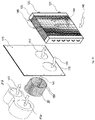
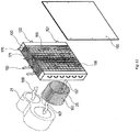
Figs. 6 to 11 an alternative dryer, 100, is illustrated and parts similar to those of thedryer 1 are given the same reference numerals. Thedryer 100 has anouter casing 102 with aback panel 104 having a grille. In this case there is adrum manifold 110, which is dish-shaped as is conventional. However it has a cut-out in the lower side to receive anelectrical heater 111. Aplate 115 is fitted against the fan /manifold assembly 25/21, havingapertures manifold outlet 27. When arectangular heat exchanger 120 is placed against theplate 115 it is in line with theelectrical heater 111 and the interior of thedrum manifold 110. Theheat exchanger 120 has water inlet andoutlet couplers motor 11 drives thebelt 12 and thefan 25, as in the above embodiment. - The
heat exchanger 120 has copper tubes and aluminium fins. The copper pipes are mechanically crimped in the fins, and these are provided with small collars which increase the surface of exchange between each other. The fins have an aluminium surface slightly waved to improve the quality of the thermic exchange by effect of turbulence. This characteristic does not modify significantly the pressure drop created on the air. The standard space between the fins is of 2.1 mm. In another embodiment, the heat exchanger may have an "AIRA" air curtain design fitted in order to provide additional regulation to air flow. - The tubes are made of copper reels of 10mm tubes directly formed to dimension. After the expansion process in the fin the internal surface is smooth to reduce water pressure drop. The frames are of galvanised steel, to ensure rigidity of the set and protect the copper and the aluminium from contact with sharp elements. It allows the mounting of the exchanger on gliders. The collectors are made of copper, arranged to collect the parallel circuits of the heat exchanger and gather them into one single main circuit. The distributor/capillaries are welded to allow a well balanced distribution of the liquid in the parallel circuits of the tube/coils.
Heat Exchanger Finned Height 302mm Fin Spacing, 2.1mm Tubes CU.30 Fins AL.10 Weight 4.10kg Primary Surface 0.20m2 Secondary Surface 3.20m2 Volume of tubes 0.68dm3 - In use,
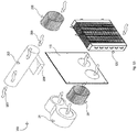
inlet air 140 flows into theheat exchanger 120, through the gaps between the heat exchanger fins 124 (through whichtubes 123 extend). Thefins 124 are vertically aligned and so flow 140 can continue through theheat exchanger 120 and into the fan/manifold assembly 25/21 as afirst pass flow 141. Thefan 25 hasblades 150 curved with a convex surface facing in the (clockwise, as viewed from the heat exchanger) direction of travel. Thefan 25 delivers air in alateral flow 142 across the manifold 21 and from there it flows in asecond pass 143 back into theheat exchanger 120. Due to agap 130 between thepanel 104 and thefins 124 some air flows (144) laterally across the back of the heat exchanger. It is drawn back in by the first pass orinlet flow 140/141, to mix with the first pass air, so that some of the flow into thefan 25 is heated twice. The flow along thefins 124 is shown by thearrows 145. The final heated air exits the heat exchanger on the top right as viewed from the rear, in aflow 146. - In one example of use, water flows into the heat exchanger at an average rate of 68 1/hr, and there is a pressure drop of 0.12 kPa across the heat exchanger.
- The following is a set of test data for performance of the
dryer 100. - 1) At 75°C hot water supply:
- 7kg wet clothes, 80 minutes drying time
- 3kg wet clothes, 60 minutes drying time
- 2) At 60°C hot water supply:
7kgwet clothes 110 to 120 minutes drying time - 3) At 56°C hot water supply
6kg wet clothes, 160 minutes drying time. - In one test the air flow rate was up to 16m3/h.
- A 55 minute wash with a 1400rpm spin cycle was utilised to wash clothes to ensure clothes were prepared for each drying test cycle and presented in similar conditions and identical weights.
- The air speed into the heat exchanger at the
inlet 116 for the above was 12 m/s, and the speed out of themanifold outlet 117 was 18 m/s. - Referring to
Fig. 12 an alternative heat exchange assembly for a dryer of the invention has parts similar to the above embodiments indicated by the same reference numerals. In this case there is a plate 160 behind and in contact with the rear of theheat exchanger 120. This completely seals off the rear of the heat exchanger in the sense of preventing lateral flow across. However, there is space above the heat exchanger fins on the left side as viewed inFig. 12 . Hence, there is aflow 165/166 downwardly and into the fins, forwardly 167 under action of thefan 25, out (168) of the manifold, up (169) through the fins, and finally out (170) into the drum manifold. There is also mixing in this embodiment because there is an enclosed space above the fins on the right (as viewed from the rear). Second pass air can travel across ((171) to be drawn into thefirst pass air 165/166. - In this embodiment there is even higher efficiency because the
air 165 will be pre-heated to some extent before it reaches the heat exchanger, by contact with the drum. - Referring to
Fig. 13 a condenser dryer embodiment has aheat exchange assembly 200, and again like parts are given the same reference numerals. There is acondenser tubular section 203 and afan 205 for drawing in cool air to cause condensation into awater trap 206. Hence the provision of a heat exchanger does not reduce flexibility in dryer configuration, both air exhaust and condenser types can be readily provided. - The dryer of the various embodiments has the major benefit of achieving exceptional energy efficiency by using heat which is available anyway in most buildings, but at the same time requiring little configuration and size difference from the known electric-only dryers. Because the fan (25) is arranged to pull air through the heat exchanger it is particularly efficient to direct it in a manner to optimise heat transfer with the multiple passes, possible involving mixing. Use of a centrifugal fan having curved blades with convex surfaces facing in a direction or rotation allows particularly effective drawing of air from space around the heat exchanger in the first pass and then to change direction for the second pass, of in embodiments with only one pass, for onward flow to the drum. If there is only one pass, it is preferable that the heat exchanger be more aligned in the flow direction.
- The fan being arranged to direct air through the heat exchanger in a first pass and back into the heat exchanger in at least one further pass, provides particularly efficient heat transfer and compactness of the heat transfer assembly. The manifold mounted adjacent the heat exchanger also contributes significantly to compactness. It is a very advantageous way to draw ambient air through a portion of the heat exchanger and to blow the air back into a different portion of the heat exchanger. Because these portions are spaced apart in the lateral dimension (horizontal in use), the heat exchanger may be configured to be shallow but wide (approximately planar configuration), allowing it to fit in the housing in a compact manner. In embodiments where the manifold inlet has a larger cross-sectional area than the manifold outlet, there is a higher flow rate in the second pass, helping spread of the air across the heat exchanger and also upwardly to the drum. It has been found that it is advantageous if the manifold outlet has a cross-sectional area in the range of 30% to 80% of that of the inlet. Where the fan and the heat exchanger are arranged to allow some first pass air to mix with second pass air, a higher temperature can be achieved without unduly sacrificing fan efficiency. A diverter such as a plate is a particularly effective and compact way of causing second pass air to spread across the heat exchanger and into the path of first pass air.
- By having elongate parallel elements, the air can flow alongside and perpendicular to said elongate elements until it is drawn into volumes between said elongate elements by first pass air, and moreover it is directed towards the drum. The fins therefore influence both heat transfer and direction of air travel while guiding air towards the drum. Where the heater includes an electrical element the controller is configured to engage or energise the electrical element when no alternative heat source is available; this dual facility ultimately increases the versatility for the end user.
- Where the electrical heating element is forward of the manifold or the heat exchanger or both, recycled air flow acts as an effective cleanser of all components from flint/fluff due to the multidirectional travel of air-flow during all operations of this system. There is advantageously very effective blowing of fluff off the electrical element.
- This is in contrast to many known dryers, in which the fan is directly downstream of the drum, and so is acing to pull air across the element via the drum and the clothes within. On the other hand, by having the fan blow air across the element there is much less risk of fluff depositing on the element and the attendant fire risk.
- Where fan is arranged to be driven by the drum drive mechanism, the dryer can be particularly compact and have few parts.
- The invention is not limited to the embodiments described but may be varied in construction and detail. For example the dryer may be of a capacity suitable for commercial use. It is preferable, but not essential, that air is drawn in through the heat exchanger for the electrical mode of operation. In an alternative embodiment the air flow components draw air and pump it in an in-line axial manner through a heat exchanger without mixing. Such a heat exchanger may be in the form of baffles in an air flow duct. Also, the heat exchanger may comprise an assembly of more than one physical unit mounted together.
Claims (15)
- A clothes dryer comprising:a controller,a housing (2),a drum (10),a drum drive mechanism (11, 12),a drum hot air inlet (23),a heater (20, 24), andan air fan (25) for pumping air through the heater en route to the drum hot air inlet, wherein the heater includes a heat exchanger (20, 120) having a coupling (20(a), 20(b)) for connection to a supply of hot water or other liquid,characterized in that,the air fan is arranged to direct air through the heat exchanger in a first pass (141, 142) and back into the heat exchanger (20, 120) in at least one further pass (143).
- A clothes dryer as claimed in claim 1, wherein the air fan (25) is arranged to pull air through the heat exchanger (20, 120), and optionally the air fan (25) is a centrifugal fan having curved blades with convex surfaces facing in a direction of rotation.
- A clothes dryer as claimed in claim 2, wherein the air fan (25) is arranged to axially pull air through the heat exchanger (20) and into an internal volume of said air fan (25).
- A clothes dryer as claimed in any preceding claim, wherein the air fan (25) is in a manifold (21) mounted adjacent the heat exchanger (20, 120) and is arranged (21) to pull air through the heat exchanger and into the manifold through a manifold inlet (26) in said first pass, and to blow heated air through a manifold outlet (27) and into the heat exchanger in said further pass.
- A clothes dryer as claimed in claim 4, wherein the air fan (25) and the manifold (21) are arranged to:draw (14) ambient air through a portion of the heat exchanger (120) and into the manifold (21), andblow said air (143) back into a different portion of the heat exchanger (20, 120).
- A clothes dryer as claimed in claim 5, wherein said portions of the heat exchanger (20, 120) are spaced apart in a lateral dimension across the dryer, and wherein the air fan and the heat exchanger are arranged to provide sufficient air pressure to cause air (144, 145) in said further pass to spread through at least part of the heat exchanger (20, 120) before exiting (146) at an upper heat exchanger outlet.
- A clothes dryer as claimed in any of claims 4 to 6, wherein the air fan is a centrifugal fan (25) mounted to draw said first pass air axially into a volume of the fan, and to blow it laterally within the manifold (21) with sufficient pressure to exhaust the manifold and enter the heat exchanger in said further pass.
- A clothes dryer as claimed in any of claims 4 to 7, wherein said manifold inlet (26) has a larger cross-sectional area than said manifold outlet (27), and wherein the manifold outlet has a cross-sectional area in the range of 25% to 90% of the cross-sectional area of the manifold inlet.
- A clothes dryer as claimed in any preceding claim, wherein the air fan and the heat exchanger (20, 120) are arranged to allow some first pass air to mix with further pass air.
- A clothes dryer as claimed in claim 9, wherein the dryer comprises a diverter (30, 104) for diverting further pass air across the heat exchanger and into a path of said first pass air, and optionally the diverter comprises a plate (30, 104) bordering or spaced apart from the heat exchanger (20, 120), and optionally wherein the plate is normal to a direction of said further pass air flow through the heat exchanger.
- A clothes dryer as claimed in claim 10, wherein the heat exchanger comprises elongate parallel elements (124), and the diverter (104) is spaced apart from said elongate parallel elements to define a volume (130) within which said second pass air (144) can flow alongside and perpendicular to said elongate parallel elements until it is drawn into volumes between said elongate parallel elements by said first pass air, and optionally the diverter (104) is located on a side of the heat exchanger opposed to the fan (25), and optionally the diverter includes an aperture for flow of first pass air into the heat exchanger.
- A clothes dryer as claimed in any preceding claim, wherein the heater includes an electrical element (24), and the controller is configured to operate the electrical element (24) if heat is not available to the heat exchanger, and the electrical element (24) is in a drum air inlet manifold (23) of said drum hot air inlet, and optionally the heat exchanger (20, 120) is below and operatively connected to the drum inlet manifold (23).
- A clothes dryer as claimed in any preceding claim, wherein the heat exchanger (20, 120) comprises heat exchange tubes extending through fins, and the fins (124) are arranged in a direction aligned with the drum hot air inlet (23, 110).
- A clothes dryer as claimed in any preceding claim, wherein the air fan (25) is arranged to be driven by the drum drive mechanism (11), and optionally the air fan is on an outlet shaft of a motor of said drum drive mechanism (11).
- A clothes dryer as claimed in any preceding claim, further comprising a valve for blocking flow of hot water to the heat exchanger for part of a drying cycle, and the controller is arranged to control operation of said valve, for a phase of operation such as a cooling down period.
Applications Claiming Priority (3)
| Application Number | Priority Date | Filing Date | Title |
|---|---|---|---|
| EP14195007 | 2014-11-26 | ||
| EP15178934 | 2015-07-29 | ||
| PCT/EP2015/077101 WO2016083235A1 (en) | 2014-11-26 | 2015-11-19 | A clothes dryer |
Publications (2)
| Publication Number | Publication Date |
|---|---|
| EP3224403A1 EP3224403A1 (en) | 2017-10-04 |
| EP3224403B1 true EP3224403B1 (en) | 2019-08-14 |
Family
ID=54557437
Family Applications (1)
| Application Number | Title | Priority Date | Filing Date |
|---|---|---|---|
| EP15797111.0A Active EP3224403B1 (en) | 2014-11-26 | 2015-11-19 | A clothes dryer |
Country Status (3)
| Country | Link |
|---|---|
| US (1) | US20170247831A1 (en) |
| EP (1) | EP3224403B1 (en) |
| WO (1) | WO2016083235A1 (en) |
Families Citing this family (2)
| Publication number | Priority date | Publication date | Assignee | Title |
|---|---|---|---|---|
| US10184204B1 (en) * | 2017-06-30 | 2019-01-22 | Wayde L. Wood | Adjustable vent register dryer |
| US11851807B2 (en) | 2019-11-07 | 2023-12-26 | Whirlpool Corporation | Method of removing heat from a clothes tumbling system on the outside of the cabinet |
Family Cites Families (14)
| Publication number | Priority date | Publication date | Assignee | Title |
|---|---|---|---|---|
| US2752694A (en) * | 1953-06-15 | 1956-07-03 | Gen Motors Corp | Domestic appliance |
| US3229379A (en) * | 1963-03-18 | 1966-01-18 | Gen Electric | Control system for fabric dryer |
| US3516174A (en) * | 1968-02-26 | 1970-06-23 | Fedders Corp | Control arrangement for dry cleaning machines |
| DE2806873C3 (en) * | 1978-02-17 | 1981-03-26 | Bauknecht Hausgeräte GmbH, 70565 Stuttgart | Drum washing and drying machine |
| DE3939744A1 (en) | 1989-12-01 | 1991-06-06 | Licentia Gmbh | HOUSEHOLD LAUNDRY DRYER |
| JP3605067B2 (en) * | 2001-11-14 | 2004-12-22 | 三洋電機株式会社 | Drum type washer / dryer |
| US6941680B1 (en) | 2003-07-03 | 2005-09-13 | Robert Zielewicz | Cost-efficient clothes dryer |
| KR100595763B1 (en) * | 2004-12-07 | 2006-06-30 | 엘지전자 주식회사 | Clothes dryer with a dehumidifier |
| WO2009026591A1 (en) * | 2007-08-23 | 2009-02-26 | Meb Ip, Llc | Heat delivery system for a fabric care appliance |
| KR20120088034A (en) * | 2010-10-19 | 2012-08-08 | 엘지전자 주식회사 | laundry machine having a drying function |
| JP2012218759A (en) * | 2011-04-07 | 2012-11-12 | Jrf International Inc | Power generating container |
| IES86294B2 (en) | 2011-06-10 | 2013-11-06 | James Hayes | Clothes dryer |
| WO2014116001A1 (en) * | 2013-01-25 | 2014-07-31 | Lg Electronics Inc. | Laundry treatment apparatus |
| US8973286B1 (en) * | 2014-01-27 | 2015-03-10 | Elwha Llc | Vacuum assisted dryer systems and methods |
-
2015
- 2015-11-19 US US15/526,928 patent/US20170247831A1/en not_active Abandoned
- 2015-11-19 EP EP15797111.0A patent/EP3224403B1/en active Active
- 2015-11-19 WO PCT/EP2015/077101 patent/WO2016083235A1/en active Application Filing
Non-Patent Citations (1)
| Title |
|---|
| None * |
Also Published As
| Publication number | Publication date |
|---|---|
| EP3224403A1 (en) | 2017-10-04 |
| WO2016083235A1 (en) | 2016-06-02 |
| US20170247831A1 (en) | 2017-08-31 |
Similar Documents
| Publication | Publication Date | Title |
|---|---|---|
| JP6270983B2 (en) | Cooling tower with indirect heat exchanger | |
| TW200912083A (en) | Clothes dryer | |
| CN104501317A (en) | Outdoor heat exchange structure for bidirectional air suction type air conditioner | |
| EP3224403B1 (en) | A clothes dryer | |
| WO2011003795A1 (en) | Clothes drying apparatus | |
| US10612184B2 (en) | Hydronic drying machine | |
| CN208606497U (en) | A kind of efficient in line dryer of recovery type heat air source heat pump | |
| US20160362830A1 (en) | Vented clothes dryer with passive heat recovery | |
| CN107435228A (en) | Dryer | |
| CN105571097A (en) | Air-inlet grille of air conditioner indoor unit and air conditioner | |
| IE86865B1 (en) | A clothes dryer | |
| CN105780425A (en) | Washing machine and drying device thereof | |
| CN202066251U (en) | Multi-section heat exchanger and cabinet air conditioner with same | |
| EP2452008B1 (en) | Clothes drying apparatus | |
| CN210242191U (en) | Drying mechanism with condensing equipment for heat treatment cleaning machine | |
| JP2011092510A (en) | Clothes dryer | |
| CN210718371U (en) | Drying machine | |
| JP2008057861A (en) | Air conditioner | |
| WO2017194531A1 (en) | A laundry washing-drying machine comprising a water-cooled condenser | |
| US1819608A (en) | Heating apparatus | |
| CN212253160U (en) | Hot water system with drying function | |
| EP3660193A1 (en) | Clothes drying appliance | |
| CN111254671B (en) | Heat exchange device and clothes drying appliance with same | |
| JP2002364873A5 (en) | ||
| JP3480869B2 (en) | Air conditioner |
Legal Events
| Date | Code | Title | Description |
|---|---|---|---|
| STAA | Information on the status of an ep patent application or granted ep patent |
Free format text: STATUS: THE INTERNATIONAL PUBLICATION HAS BEEN MADE |
|
| PUAI | Public reference made under article 153(3) epc to a published international application that has entered the european phase |
Free format text: ORIGINAL CODE: 0009012 |
|
| STAA | Information on the status of an ep patent application or granted ep patent |
Free format text: STATUS: REQUEST FOR EXAMINATION WAS MADE |
|
| 17P | Request for examination filed |
Effective date: 20170510 |
|
| AK | Designated contracting states |
Kind code of ref document: A1 Designated state(s): AL AT BE BG CH CY CZ DE DK EE ES FI FR GB GR HR HU IE IS IT LI LT LU LV MC MK MT NL NO PL PT RO RS SE SI SK SM TR |
|
| AX | Request for extension of the european patent |
Extension state: BA ME |
|
| DAV | Request for validation of the european patent (deleted) | ||
| DAX | Request for extension of the european patent (deleted) | ||
| GRAP | Despatch of communication of intention to grant a patent |
Free format text: ORIGINAL CODE: EPIDOSNIGR1 |
|
| STAA | Information on the status of an ep patent application or granted ep patent |
Free format text: STATUS: GRANT OF PATENT IS INTENDED |
|
| RIC1 | Information provided on ipc code assigned before grant |
Ipc: D06F 58/26 20060101AFI20180629BHEP Ipc: D06F 58/10 20060101ALN20180629BHEP Ipc: D06F 58/02 20060101ALN20180629BHEP Ipc: D06F 58/20 20060101ALN20180629BHEP |
|
| INTG | Intention to grant announced |
Effective date: 20180803 |
|
| GRAJ | Information related to disapproval of communication of intention to grant by the applicant or resumption of examination proceedings by the epo deleted |
Free format text: ORIGINAL CODE: EPIDOSDIGR1 |
|
| STAA | Information on the status of an ep patent application or granted ep patent |
Free format text: STATUS: REQUEST FOR EXAMINATION WAS MADE |
|
| INTC | Intention to grant announced (deleted) | ||
| RBV | Designated contracting states (corrected) |
Designated state(s): AL AT BE BG CH CY CZ DE DK EE ES FI FR GB GR HR HU IS IT LI LT LU LV MC MK MT NL NO PL PT RO RS SE SI SK SM TR |
|
| GRAS | Grant fee paid |
Free format text: ORIGINAL CODE: EPIDOSNIGR3 |
|
| STAA | Information on the status of an ep patent application or granted ep patent |
Free format text: STATUS: GRANT OF PATENT IS INTENDED |
|
| GRAP | Despatch of communication of intention to grant a patent |
Free format text: ORIGINAL CODE: EPIDOSNIGR1 |
|
| RIC1 | Information provided on ipc code assigned before grant |
Ipc: D06F 58/10 20060101ALN20190531BHEP Ipc: D06F 58/26 20060101AFI20190531BHEP Ipc: D06F 58/20 20060101ALN20190531BHEP Ipc: D06F 58/02 20060101ALN20190531BHEP |
|
| GRAA | (expected) grant |
Free format text: ORIGINAL CODE: 0009210 |
|
| STAA | Information on the status of an ep patent application or granted ep patent |
Free format text: STATUS: THE PATENT HAS BEEN GRANTED |
|
| INTG | Intention to grant announced |
Effective date: 20190626 |
|
| AK | Designated contracting states |
Kind code of ref document: B1 Designated state(s): AL AT BE BG CH CY CZ DE DK EE ES FI FR GB GR HR HU IS IT LI LT LU LV MC MK MT NL NO PL PT RO RS SE SI SK SM TR |
|
| REG | Reference to a national code |
Ref country code: GB Ref legal event code: FG4D |
|
| REG | Reference to a national code |
Ref country code: CH Ref legal event code: EP Ref country code: AT Ref legal event code: REF Ref document number: 1167166 Country of ref document: AT Kind code of ref document: T Effective date: 20190815 |
|
| REG | Reference to a national code |
Ref country code: DE Ref legal event code: R096 Ref document number: 602015035926 Country of ref document: DE |
|
| REG | Reference to a national code |
Ref country code: NL Ref legal event code: MP Effective date: 20190814 |
|
| REG | Reference to a national code |
Ref country code: LT Ref legal event code: MG4D |
|
| PG25 | Lapsed in a contracting state [announced via postgrant information from national office to epo] |
Ref country code: PT Free format text: LAPSE BECAUSE OF FAILURE TO SUBMIT A TRANSLATION OF THE DESCRIPTION OR TO PAY THE FEE WITHIN THE PRESCRIBED TIME-LIMIT Effective date: 20191216 Ref country code: BG Free format text: LAPSE BECAUSE OF FAILURE TO SUBMIT A TRANSLATION OF THE DESCRIPTION OR TO PAY THE FEE WITHIN THE PRESCRIBED TIME-LIMIT Effective date: 20191114 Ref country code: LT Free format text: LAPSE BECAUSE OF FAILURE TO SUBMIT A TRANSLATION OF THE DESCRIPTION OR TO PAY THE FEE WITHIN THE PRESCRIBED TIME-LIMIT Effective date: 20190814 Ref country code: NL Free format text: LAPSE BECAUSE OF FAILURE TO SUBMIT A TRANSLATION OF THE DESCRIPTION OR TO PAY THE FEE WITHIN THE PRESCRIBED TIME-LIMIT Effective date: 20190814 Ref country code: HR Free format text: LAPSE BECAUSE OF FAILURE TO SUBMIT A TRANSLATION OF THE DESCRIPTION OR TO PAY THE FEE WITHIN THE PRESCRIBED TIME-LIMIT Effective date: 20190814 Ref country code: SE Free format text: LAPSE BECAUSE OF FAILURE TO SUBMIT A TRANSLATION OF THE DESCRIPTION OR TO PAY THE FEE WITHIN THE PRESCRIBED TIME-LIMIT Effective date: 20190814 Ref country code: NO Free format text: LAPSE BECAUSE OF FAILURE TO SUBMIT A TRANSLATION OF THE DESCRIPTION OR TO PAY THE FEE WITHIN THE PRESCRIBED TIME-LIMIT Effective date: 20191114 Ref country code: FI Free format text: LAPSE BECAUSE OF FAILURE TO SUBMIT A TRANSLATION OF THE DESCRIPTION OR TO PAY THE FEE WITHIN THE PRESCRIBED TIME-LIMIT Effective date: 20190814 |
|
| REG | Reference to a national code |
Ref country code: AT Ref legal event code: MK05 Ref document number: 1167166 Country of ref document: AT Kind code of ref document: T Effective date: 20190814 |
|
| PG25 | Lapsed in a contracting state [announced via postgrant information from national office to epo] |
Ref country code: AL Free format text: LAPSE BECAUSE OF FAILURE TO SUBMIT A TRANSLATION OF THE DESCRIPTION OR TO PAY THE FEE WITHIN THE PRESCRIBED TIME-LIMIT Effective date: 20190814 Ref country code: GR Free format text: LAPSE BECAUSE OF FAILURE TO SUBMIT A TRANSLATION OF THE DESCRIPTION OR TO PAY THE FEE WITHIN THE PRESCRIBED TIME-LIMIT Effective date: 20191115 Ref country code: ES Free format text: LAPSE BECAUSE OF FAILURE TO SUBMIT A TRANSLATION OF THE DESCRIPTION OR TO PAY THE FEE WITHIN THE PRESCRIBED TIME-LIMIT Effective date: 20190814 Ref country code: IS Free format text: LAPSE BECAUSE OF FAILURE TO SUBMIT A TRANSLATION OF THE DESCRIPTION OR TO PAY THE FEE WITHIN THE PRESCRIBED TIME-LIMIT Effective date: 20191214 Ref country code: RS Free format text: LAPSE BECAUSE OF FAILURE TO SUBMIT A TRANSLATION OF THE DESCRIPTION OR TO PAY THE FEE WITHIN THE PRESCRIBED TIME-LIMIT Effective date: 20190814 Ref country code: LV Free format text: LAPSE BECAUSE OF FAILURE TO SUBMIT A TRANSLATION OF THE DESCRIPTION OR TO PAY THE FEE WITHIN THE PRESCRIBED TIME-LIMIT Effective date: 20190814 |
|
| PG25 | Lapsed in a contracting state [announced via postgrant information from national office to epo] |
Ref country code: TR Free format text: LAPSE BECAUSE OF FAILURE TO SUBMIT A TRANSLATION OF THE DESCRIPTION OR TO PAY THE FEE WITHIN THE PRESCRIBED TIME-LIMIT Effective date: 20190814 |
|
| PG25 | Lapsed in a contracting state [announced via postgrant information from national office to epo] |
Ref country code: RO Free format text: LAPSE BECAUSE OF FAILURE TO SUBMIT A TRANSLATION OF THE DESCRIPTION OR TO PAY THE FEE WITHIN THE PRESCRIBED TIME-LIMIT Effective date: 20190814 Ref country code: EE Free format text: LAPSE BECAUSE OF FAILURE TO SUBMIT A TRANSLATION OF THE DESCRIPTION OR TO PAY THE FEE WITHIN THE PRESCRIBED TIME-LIMIT Effective date: 20190814 Ref country code: AT Free format text: LAPSE BECAUSE OF FAILURE TO SUBMIT A TRANSLATION OF THE DESCRIPTION OR TO PAY THE FEE WITHIN THE PRESCRIBED TIME-LIMIT Effective date: 20190814 Ref country code: IT Free format text: LAPSE BECAUSE OF FAILURE TO SUBMIT A TRANSLATION OF THE DESCRIPTION OR TO PAY THE FEE WITHIN THE PRESCRIBED TIME-LIMIT Effective date: 20190814 Ref country code: DK Free format text: LAPSE BECAUSE OF FAILURE TO SUBMIT A TRANSLATION OF THE DESCRIPTION OR TO PAY THE FEE WITHIN THE PRESCRIBED TIME-LIMIT Effective date: 20190814 Ref country code: PL Free format text: LAPSE BECAUSE OF FAILURE TO SUBMIT A TRANSLATION OF THE DESCRIPTION OR TO PAY THE FEE WITHIN THE PRESCRIBED TIME-LIMIT Effective date: 20190814 |
|
| PG25 | Lapsed in a contracting state [announced via postgrant information from national office to epo] |
Ref country code: SK Free format text: LAPSE BECAUSE OF FAILURE TO SUBMIT A TRANSLATION OF THE DESCRIPTION OR TO PAY THE FEE WITHIN THE PRESCRIBED TIME-LIMIT Effective date: 20190814 Ref country code: SM Free format text: LAPSE BECAUSE OF FAILURE TO SUBMIT A TRANSLATION OF THE DESCRIPTION OR TO PAY THE FEE WITHIN THE PRESCRIBED TIME-LIMIT Effective date: 20190814 Ref country code: IS Free format text: LAPSE BECAUSE OF FAILURE TO SUBMIT A TRANSLATION OF THE DESCRIPTION OR TO PAY THE FEE WITHIN THE PRESCRIBED TIME-LIMIT Effective date: 20200224 Ref country code: CZ Free format text: LAPSE BECAUSE OF FAILURE TO SUBMIT A TRANSLATION OF THE DESCRIPTION OR TO PAY THE FEE WITHIN THE PRESCRIBED TIME-LIMIT Effective date: 20190814 |
|
| REG | Reference to a national code |
Ref country code: DE Ref legal event code: R097 Ref document number: 602015035926 Country of ref document: DE |
|
| REG | Reference to a national code |
Ref country code: CH Ref legal event code: PL |
|
| PLBE | No opposition filed within time limit |
Free format text: ORIGINAL CODE: 0009261 |
|
| STAA | Information on the status of an ep patent application or granted ep patent |
Free format text: STATUS: NO OPPOSITION FILED WITHIN TIME LIMIT |
|
| PG2D | Information on lapse in contracting state deleted |
Ref country code: IS |
|
| PG25 | Lapsed in a contracting state [announced via postgrant information from national office to epo] |
Ref country code: LU Free format text: LAPSE BECAUSE OF NON-PAYMENT OF DUE FEES Effective date: 20191119 Ref country code: MC Free format text: LAPSE BECAUSE OF FAILURE TO SUBMIT A TRANSLATION OF THE DESCRIPTION OR TO PAY THE FEE WITHIN THE PRESCRIBED TIME-LIMIT Effective date: 20190814 Ref country code: CH Free format text: LAPSE BECAUSE OF NON-PAYMENT OF DUE FEES Effective date: 20191130 Ref country code: LI Free format text: LAPSE BECAUSE OF NON-PAYMENT OF DUE FEES Effective date: 20191130 |
|
| 26N | No opposition filed |
Effective date: 20200603 |
|
| REG | Reference to a national code |
Ref country code: BE Ref legal event code: MM Effective date: 20191130 |
|
| PG25 | Lapsed in a contracting state [announced via postgrant information from national office to epo] |
Ref country code: SI Free format text: LAPSE BECAUSE OF FAILURE TO SUBMIT A TRANSLATION OF THE DESCRIPTION OR TO PAY THE FEE WITHIN THE PRESCRIBED TIME-LIMIT Effective date: 20190814 |
|
| PG25 | Lapsed in a contracting state [announced via postgrant information from national office to epo] |
Ref country code: FR Free format text: LAPSE BECAUSE OF NON-PAYMENT OF DUE FEES Effective date: 20191130 |
|
| PG25 | Lapsed in a contracting state [announced via postgrant information from national office to epo] |
Ref country code: BE Free format text: LAPSE BECAUSE OF NON-PAYMENT OF DUE FEES Effective date: 20191130 |
|
| PG25 | Lapsed in a contracting state [announced via postgrant information from national office to epo] |
Ref country code: CY Free format text: LAPSE BECAUSE OF FAILURE TO SUBMIT A TRANSLATION OF THE DESCRIPTION OR TO PAY THE FEE WITHIN THE PRESCRIBED TIME-LIMIT Effective date: 20190814 |
|
| PG25 | Lapsed in a contracting state [announced via postgrant information from national office to epo] |
Ref country code: MT Free format text: LAPSE BECAUSE OF FAILURE TO SUBMIT A TRANSLATION OF THE DESCRIPTION OR TO PAY THE FEE WITHIN THE PRESCRIBED TIME-LIMIT Effective date: 20190814 Ref country code: HU Free format text: LAPSE BECAUSE OF FAILURE TO SUBMIT A TRANSLATION OF THE DESCRIPTION OR TO PAY THE FEE WITHIN THE PRESCRIBED TIME-LIMIT; INVALID AB INITIO Effective date: 20151119 |
|
| PG25 | Lapsed in a contracting state [announced via postgrant information from national office to epo] |
Ref country code: MK Free format text: LAPSE BECAUSE OF FAILURE TO SUBMIT A TRANSLATION OF THE DESCRIPTION OR TO PAY THE FEE WITHIN THE PRESCRIBED TIME-LIMIT Effective date: 20190814 |
|
| P01 | Opt-out of the competence of the unified patent court (upc) registered |
Effective date: 20230419 |
|
| PGFP | Annual fee paid to national office [announced via postgrant information from national office to epo] |
Ref country code: GB Payment date: 20231121 Year of fee payment: 9 |
|
| PGFP | Annual fee paid to national office [announced via postgrant information from national office to epo] |
Ref country code: DE Payment date: 20231120 Year of fee payment: 9 |