EP3659957B1 - Elevator car door operator device - Google Patents
Elevator car door operator device Download PDFInfo
- Publication number
- EP3659957B1 EP3659957B1 EP18871254.1A EP18871254A EP3659957B1 EP 3659957 B1 EP3659957 B1 EP 3659957B1 EP 18871254 A EP18871254 A EP 18871254A EP 3659957 B1 EP3659957 B1 EP 3659957B1
- Authority
- EP
- European Patent Office
- Prior art keywords
- door
- movable vane
- car door
- vane
- landing
- Prior art date
- Legal status (The legal status is an assumption and is not a legal conclusion. Google has not performed a legal analysis and makes no representation as to the accuracy of the status listed.)
- Active
Links
- 238000003825 pressing Methods 0.000 claims description 39
- 230000000903 blocking effect Effects 0.000 claims description 37
- 230000001360 synchronised effect Effects 0.000 claims description 35
- 230000006835 compression Effects 0.000 claims description 26
- 238000007906 compression Methods 0.000 claims description 26
- 239000000725 suspension Substances 0.000 claims description 25
- 230000000694 effects Effects 0.000 claims description 12
- 238000000034 method Methods 0.000 claims description 9
- 238000006073 displacement reaction Methods 0.000 claims description 8
- 230000005484 gravity Effects 0.000 claims description 8
- 230000003068 static effect Effects 0.000 claims description 4
- 230000001133 acceleration Effects 0.000 description 4
- 238000005452 bending Methods 0.000 description 4
- 238000003466 welding Methods 0.000 description 3
- 229910000831 Steel Inorganic materials 0.000 description 2
- 238000006243 chemical reaction Methods 0.000 description 2
- 238000005516 engineering process Methods 0.000 description 2
- 238000009987 spinning Methods 0.000 description 2
- 239000010959 steel Substances 0.000 description 2
- 230000008878 coupling Effects 0.000 description 1
- 238000010168 coupling process Methods 0.000 description 1
- 238000005859 coupling reaction Methods 0.000 description 1
- KRTSDMXIXPKRQR-AATRIKPKSA-N monocrotophos Chemical compound CNC(=O)\C=C(/C)OP(=O)(OC)OC KRTSDMXIXPKRQR-AATRIKPKSA-N 0.000 description 1
Images


Classifications
-
- B—PERFORMING OPERATIONS; TRANSPORTING
- B66—HOISTING; LIFTING; HAULING
- B66B—ELEVATORS; ESCALATORS OR MOVING WALKWAYS
- B66B13/00—Doors, gates, or other apparatus controlling access to, or exit from, cages or lift well landings
- B66B13/02—Door or gate operation
- B66B13/14—Control systems or devices
- B66B13/16—Door or gate locking devices controlled or primarily controlled by condition of cage, e.g. movement or position
- B66B13/18—Door or gate locking devices controlled or primarily controlled by condition of cage, e.g. movement or position without manually-operable devices for completing locking or unlocking of doors
- B66B13/20—Lock mechanisms actuated mechanically by abutments or projections on the cages
-
- B—PERFORMING OPERATIONS; TRANSPORTING
- B66—HOISTING; LIFTING; HAULING
- B66B—ELEVATORS; ESCALATORS OR MOVING WALKWAYS
- B66B13/00—Doors, gates, or other apparatus controlling access to, or exit from, cages or lift well landings
- B66B13/02—Door or gate operation
- B66B13/12—Arrangements for effecting simultaneous opening or closing of cage and landing doors
-
- E—FIXED CONSTRUCTIONS
- E05—LOCKS; KEYS; WINDOW OR DOOR FITTINGS; SAFES
- E05Y—INDEXING SCHEME RELATING TO HINGES OR OTHER SUSPENSION DEVICES FOR DOORS, WINDOWS OR WINGS AND DEVICES FOR MOVING WINGS INTO OPEN OR CLOSED POSITION, CHECKS FOR WINGS AND WING FITTINGS NOT OTHERWISE PROVIDED FOR, CONCERNED WITH THE FUNCTIONING OF THE WING
- E05Y2900/00—Application of doors, windows, wings or fittings thereof
- E05Y2900/10—Application of doors, windows, wings or fittings thereof for buildings or parts thereof
- E05Y2900/104—Application of doors, windows, wings or fittings thereof for buildings or parts thereof for elevators
Definitions
- the invention relates to an elevator component, in particular relates to an elevator car door operator device.
- a door vane of a car side door operator In the process that an elevator runs up and down, when a car is in flush with a landing, a door vane of a car side door operator usually drives a landing door lock linkage roller on a landing door side to move together to realize the action of opening and closing an elevator door.
- Commonly used door vanes include synchronous door vanes and asynchronous door vanes.
- Synchronous door vanes are a kind of door vanes which firstly clamp the landing door lock linkage roller, and then the car door and the landing door move together.
- Asynchronous door vanes move simultaneously with the car door, before the car door and the landing door move together, the car door generally has to go a certain distance, and when the door is closed, asynchronous door vanes release a driving force to the landing door in a door closing direction in advance.
- US20170217732A1 discloses, in an elevator car door apparatus, a locking member is disposed on a blade-carrying car door, and is displaceable between an unlocked position and a locked position interdependently with movement of a doorstop-side blade.
- a guiding portion is disposed on the locking member.
- a guiding cam is disposed outside the blade-carrying car door.
- the locking member displaces to the locked position
- the doorstop-side blade also displaces to a locking acommodating position
- the locking member catches in a fixed latch, and movement of the blade-carrying car door in the opening direction is prevented.
- EP0763496B1 discloses, in the procedure for closing an elevator landing door, the landing door is coupled with the car door by means of a door coupler, and the car door is moved by means of an actuator provided in conjunction with the elevator car.
- the car door and landing door are moved at the same speed, but towards the end of the closing movement the landing door is caused to move faster than the car door.
- the coupling elements of the door coupler are moved in the direction of the car door movement.
- FIG. 1 illustrates a state of a landing door lock under the control of a conventional door operator device. Since asynchronous door vanes will apply the pushing force to the landing door in the door closing direction in advance when the door is closed, when the closing speed of the landing door is smaller than the car door, the landing door hook will lose control and is locked prematurely, and it will collide the fixed hook of the landing door prematurely when the door is closed, which will too quickly consume the initial kinetic energy when the landing door loses control. When there is air pressure at the landing, the sliding block at the bottom of the landing door will squeeze the side wall of the sill under the air pressure, which will increase the friction force at the bottom. When the forced door closing force is smaller than the friction force, it will cause that the landing door cannot be closed normally.
- the technical problem to be solved by the present invention is to provide an elevator car door operator device, which can prevent the landing door hook from being locked prematurely when the closing speed of the landing door is smaller than the speed of the car door.
- an elevator car door operator device comprising an elevator door operator cross beam, a door vane assembly and a door vane mounting seat, wherein the door vane mounting seat is fixedly arranged on a driving side car door, and the door vane assembly comprises: a first movable vane movably connected onto the door vane mounting seat through a connector; a second movable vane movably connected onto the door vane mounting seat through a connector and fitting with the first movable vane to clamp or loosen a landing door unlocking roller to drive a landing door to move; a first movable vane driving device rotatably connected with the first movable vane and driving the first movable vane to swing towards a direction close to the second movable vane; a protruding part arranged on the first movable vane driving device; a blocking part fixedly arranged on a static part of the elevator door operator cross beam, wherein the blocking part is capable of abutting against the
- the first movable vane driving device comprises a first swinging rod and a second swinging rod
- the first swinging rod comprises: a rotating center rotatably connected with the door vane mounting seat a first end connecting point rotatably connected with the upper part of the first movable vane; and a second end, the protruding part being arranged on the second end
- the second swinging rod comprises: a first end connecting point rotatably connected with the lower part of the first movable vane; and a second end connecting point rotatably connected with the door vane mounting seat, wherein a connecting line between the first end connecting point of the first swinging rod and the first end connecting point of the second swinging rod is always vertical, and a connecting line between the rotating center of the first swinging rod and the second end connecting point is always vertical.
- a first limiting device is arranged on the door vane mounting seat, and the first limiting device is used for limiting the distance of movement of the first movable vane towards a car door closing direction.
- the first movable vane driving device drives through self-gravity the first movable vane to swing towards a direction close to the second movable vane.
- an elastic element pressing plate device is arranged on the second swinging rod
- an elastic element guide device is arranged on the door vane mounting seat
- the elastic element guide device is connected with one end of an elastic element in a sleeving manner
- the other end of the elastic element is connected with the elastic element pressing plate device in a sleeving manner
- the elastic element applies a pressing force to the first movable vane through the elastic element pressing plate device to push the first movable vane to swing towards a direction close to the second movable vane
- the elastic element guide device fits with the elastic element pressing plate device to ensure that the first movable vane is always sleeved between the elastic element guide device and the elastic element pressing plate device in the whole swinging process.
- the protruding part is a roller.
- the protruding part is a fixed shaft.
- the blocking part is a cam
- the roller is pressed by the cam against the starting end of the cam line when the car door is fully closed; the first swinging rod rotates when the car door is opened, the cam line of the cam contacts the roller, and the rotating speed of the roller is controlled by the cam line; and the roller is far away from the cam when the first swinging rod stops rotating.
- the first limiting device is at least one limiting screw and a contact surface between the limiting screw and the door vane is wrapped with rubber.
- the elastic element pressing plate device comprises an elastic element pressing plate mounting plate, a compression spring base and a conical shaft, the pressing plate mounting plate is fixedly connected onto the second swinging rod, the compression spring base is rotatably connected onto the pressing plate mounting plate, and the conical shaft is arranged on the pressing plate mounting plate;
- the elastic element guide device is a screw, which is fixedly connected onto the door vane mounting seat; and the elastic element is a compression spring, one end of the compression spring sleeves the screw and the other end sleeves the conical shaft.
- the horizontal displacement direction produced by the protruding part in the rotation process of the first movable vane driving device is the door closing direction.
- S2 is the horizontal swinging displacement of the second movable vane towards the door closing direction after the car door is opened
- S1 is the distance between the working face of the first movable vane and the working face of the second movable vane when the door is fully closed
- D is the horizontal outer width of the landing door unlocking roller
- S4 is the horizontal swinging travel
- the elevator car door operator device further comprises a controller, a door motor, a door-in-place switch, a door-in-place switch trigger, a position switch, a position switch trigger, a door switch synchronous belt, a synchronous belt wheel, a synchronous belt tensioning device, a driving side belt suspension arm, a driving side door hanging plate, a driven side belt suspension arm, a driven side door hanging plate, a door guide rail, a door opening limiting device and a door closing limiting device; a door operator driving part, the door guide rail, the synchronous belt wheel and the synchronous belt tensioning device are arranged on the door operator cross beam, and the synchronous belt is wound in the wheel grooves of the output belt wheel of the door motor and the synchronous belt wheel at the other end, and is tensioned by the synchronous belt tensioning device; at the left and right ends of the door center, the driving side belt suspension arm and the driven side belt suspension arm are respectively arranged at the upper and lower positions of the synchronous belt, and the moving direction of
- the second movable vane swings towards the door opening direction under the control of the second movable vane action driving device to release the pushing force to the landing door lock linkage roller;
- the landing door is closed under the effect of a forced door closing force and initial kinetic energy
- the unlocking roller of the landing door eventually contacts the first movable vane and applies a pushing force to the first movable vane
- the speed of the landing door is the same as the speed of the car door, at this time the unlocking roller is always in an unlocked state, and till the landing door is closed, the first movable vane of the car door operator is far away from the unlocking roller, and the landing door unlocking roller rotates towards a locking direction under the effect of its own spring force and gravity, and finally locks the landing door;
- the door vane mounting seat 1 is mounted on a driving side car door 30.
- a shaft 6 for the first swinging rod, a shaft 7 for the second swinging rod, a shaft 23 for the third swinging rod and a shaft 24 for the fourth swinging rod are riveted on the door vane mounting seat 1 in a high-speed spinning manner.
- a shaft center connecting line between the shaft 6 for the first swinging rod and the shaft 7 for the second swinging rod is vertical.
- the shaft 6 for the first swinging rod is directly above the shaft 7 for the second swinging rod.
- the shaft center connecting line between the shaft 23 for the third swinging rod and the shaft 24 for the fourth swinging rod is vertical.
- the shaft 23 for the third swinging rod is directly above the shaft 24 for the fourth swinging rod.
- the shaft 6 for the first swinging rod and the shaft 23 for the third swinging rod have a certain horizontal distance.
- the first swinging rod 3 has a rotating center 36, and a bearing is riveted at the position of the rotating center 36.
- the end riveted bearing on one side of the rotating center 36 is hinged with the upper part of the first movable vane 2, and a hole is opened in the fitting position of the upper part of the first movable vane 2.
- a hexagonal bolt may be used as a shaft to fit with the bearing at the hinging point on one side of the rotating center 36 of the first swinging rod 3.
- a protruding part 13 is arranged on the first swinging rod 3, and preferably the protruding part is a roller.
- a shaft 14 for the roller is riveted on the first swinging rod 3 in a high-speed spinning manner, a bearing is riveted in the roller of the first swinging rod, and the roller is hinged onto the shaft 14 for the roller.
- a second end connecting point 39 is arranged on the second swinging rod 4, a bearing is riveted onto the connecting point 39, used as the rotating center of the second swinging rod 4 and is hinged with the shaft 7 for the second swinging rod of the door vane mounting seat 1, the other end of the second swinging rod 4 is riveted with a bearing which is hinged with the lower part of the first movable vane 2, a hole is opened in the hinging position of the lower part of the first movable vane 2, and a hexagonal bolt is used as a shaft.
- the first movable vane 2 uses a hexagonal bolt as a shaft, and the hexagonal bolt penetrates through the back surface of the first swinging rod, runs through the first swinging rod 3 and the bearing of the first swinging rod 3, and the first movable vane 2, and is fixed on the front surface of the first movable vane by using a nut.
- the blocking part 9 on the static part of the elevator door operator cross beam is a steel plate that has been bent for 90 degrees twice.
- the blocking part 9 has a blocking part mounting surface 51 which is mounting with the static part of the elevator door operator cross beam, a blocking part bending surface 48 which is perpendicular to the blocking part mounting surface 51, and a third surface which is perpendicular to the blocking part bending surface 48 and parallel to the blocking part mounting surface 51.
- the blocking part mounting surface 51 and the third surface are not on the same plane, but are parallel to each other.
- the side surface of the third surface is the cam line 50 of the cam.
- the door vane mounting seat 1 is a plate which is bent for 90 degree, the front surface is parallel to the surface of a door plate, and a side surface perpendicular to the front surface is formed by bending on the door closing side.
- Circular holes with diameter of 9mm are respectively opened in the upper end and the lower end of the side surface, M8 welding nuts are aligned and welded in the centers of the circular holes, and the welding nuts are on the outer side of the door vane mounting seat.
- M8 bolts wrapped with rubber at the top ends are used, the length of the bolts is 25mm, the bolts are mounted on the M8 welding nuts, and the positions of the bolts are on the inner side of the door vane mounting seat.
- the bolts on the upper side and the lower side are a first limiting device 18.
- the first movable vane 2 has mutually perpendicular surfaces, after the front surface is hinged with the first swinging rod 3 and the second swinging rod 4, the first movable vane 2 is vertical, and when the door is fully closed, the first limiting device is adjusted such that, when the side surface of the first movable vane is in contact with the first limiting device 18, the horizontal gap between the first movable vane 2 and the outer circle of the upper unlocking roller of the landing door lock is set as C1, which may be generally 9mm.
- the first swinging rod 3, the second swinging rod 4 and the first movable vane 2 form a double swinging rod mechanism.
- the gravity of the mechanism enables the first movable vane 2 to swing towards the door opening direction.
- the pressing applied by the blocking part 9 to the protruding part 13 always causes the first swinging rod 3 to clockwise rotate with the rotating center 36 as a center, and at this time the first movable vane 2 swings towards the door closing direction.
- the protruding part 13 is pressed against by the blocking part 9, the contact position is the starting end of the cam line 50 of the blocking part 9, and at this time the first movable vane 2 is limited by the first limiting device 18 and cannot continuously swing.
- one M5 threaded hole is machined in the second swinging rod 4, and an elastic element pressing plate device 61 is mounted on the threaded hole.
- the elastic element pressing plate device 61 comprises an elastic element pressing plate mounting plate 62, a compression spring base 64, and a conical shaft 65.
- the elastic element pressing plate mounting plate 62 is a steel plate which is bent for 90 degrees and consists of a front surface and a side surface. One circular hole is machined in the front surface. Through the circular hole, the elastic element pressing plate mounting plate 62 is mounted on the M5 threaded hole in the second swinging rod 4.
- a circular hole with diameter of 5 is machined in the side surface of the elastic element pressing plate mounting plate 62, and the compression spring base 64 is riveted on the circular hole at high speed.
- the compression spring base 64 is a circular surface, and the circular surface is parallel to the side surface of the elastic element pressing plate mounting plate 62.
- the conical shaft 65 is arranged on the compression spring base 64. The center of the conical shaft is concentric with the circle center of the compression spring base 64. The length of the conical shaft is 5mm.
- An M5 threaded hole is machined in the side surface of the door vane mounting seat horizontally opposite to the elastic element pressing plate mounting plate 62, an M5 screw is mounted on the threaded hole in the side surface of the door vane mounting seat, and the length of the screw may be within 12mm to 16mm.
- the angle between the side surface of the elastic element pressing plate mounting plate 62 and the side surface of the door vane mounting seat 1 may be set to 10 degrees.
- One end of the compression spring 63 sleeves the M5 screw, and the other end sleeves the conical shaft to ensure that the first movable vane 2 is not separated from the conical shaft 65 and the M5 screw 60 in the whole maximum swinging process.
- the surface of the compression spring base 64 of the elastic element pressing plate is always in contact with the compression spring 63, such that the deformation of the compression spring 63 accumulates or releases energy.
- the compression spring 63 releases energy, it pushes the first movable vane 2 to swing towards the door opening direction, and the first movable vane 2 swings towards the door closing direction to enable the compression spring 63 to accumulate energy.
- the car door operator has a full closing holding force, which can be provided by a door motor or other mechanical device.
- a door motor or other mechanical device When the door is fully closed, even if the first movable vane 2 is pushed towards the door opening direction by the compression spring 63 or the gravity of the mechanism, under the effect of the full closing holding force of the car door, the protruding part 13 of the first swinging rod is pressed against by the lower end of the blocking part 9, and the first movable vane 2 cannot swing towards the door opening direction.
- the first movable vane 2 While the car door is opened, the first movable vane 2 swings for a horizontal distance K and then contacts the landing door unlocking roller 28 to continuously open the car door.
- the first movable vane 2 continuously swings such that the landing door unlocking roller 28 swings towards the landing door lock unlocking direction until the landing door unlocking roller cannot swing.
- the centers of the landing door unlocking roller 28 and the landing door lock linkage roller 29 are on the same vertical line.
- the acceleration force to push the landing door is far greater than the driving force of the first movable vane 2.
- the driving force of the first movable vane 2 is the gravity of the double swinging rod mechanism of the first movable vane 2, or the pushing force of the compression spring 63.
- the first movable vane 2 When the car door is continuously opened, the first movable vane 2 will swing towards the door closing direction by overcoming the driving force under the acceleration reaction force that pushes the landing door. When the car door continuously moves, the first movable vane 2 swings and contacts the first limiting device 18 under the effect of the reverse pushing force of the landing door, and cannot continuously swing. At this time, it can be defined that the door opening travel of the car door is S. At this time, the acceleration force to push the landing door is provided by the first limiting device 18, and the car door and the landing door start to move together.
- the second movable vane 27 After the car door is opened, the second movable vane 27 starts to swing towards the door closing direction under the effect of the second movable vane action driving device 35.
- S1 is the distance between the working face of the first movable vane 2 and the working face of the second movable vane 27 when the door is fully closed
- D is the horizontal outer width of the landing door unlocking roller 28 and the landing door lock linkage roller 29, and generally in the existing technology, D is the outer diameter of the landing door unlocking roller or the landing door lock linkage roller.
- the horizontal gap P between the working face of the first movable vane 2 and the outer circle of the upper roller of the landing door lock is 9mm.
- the design of the blocking part 9 the design of the first swinging rod 3, the position relationship between the first rotating center 36 and the first movable vane 2 on the first swinging rod 3, the position relationship between the protruding part 13 on the first swinging rod 3 and the rotating center 36 of the first swinging rod, and the position relationship between the blocking part 9 and the rotating center 36 of the first swinging rod, the unlocking linkage process of the car door and the landing door in the unlocking area is as follows:
- the horizontal travel of the horizontal swinging of the first movable vane 2 is 9mm, and the first movable vane 2 enables the outer circle of the landing door unlocking roller 28 to rotate to a position at which the unlocking travel is the maximum.
- the centers of the landing door unlocking roller 28 and the landing door lock linkage roller 29 are on the same vertical line, and the upper roller of the landing door lock cannot continuously rotate.
- the reaction force of the acceleration force of the landing door is greater than the sum of the gravity of the first movable vane mechanism and the force in the horizontal direction of the pressing force of the compression spring 63.
- the first movable vane 2 When the car door travel is 16mm, the first movable vane 2 has rotated towards the door closing direction and has contacted the first limiting device 18, the horizontal displacement of the first movable vane 2 compared with the original one is also 16mm, and then the car door and the landing door are opened and closed in a linked manner.
- the second movable vane 27 In the opening process of the car door, the second movable vane 27 continuously swings towards the door closing direction under the control of the second movable vane action control device 35, the final horizontal swinging travel is S1-D, and thus the upper and lower rollers of the landing door are clamped.
- a triangular key is used to open the landing door.
- the landing door lock linkage roller 29 firstly contacts the second movable vane 27, and the second movable vane 27 is subjected to the pushing force such that the car door is opened.
- the first swinging rod 3 anticlockwise rotates, and the first movable vane 2 swings towards the door opening direction.
- the first movable vane 2 swings until it contacts the landing door lock linkage roller 29,
- S1 is the distance between the working face of the first movable vane 2 and the working face of the second movable vane 27 when the door is fully closed
- S1 is 72mm here
- D is the horizontal outer width of the landing door unlocking roller and the landing door lock linkage roller.
- the car door drives the landing door to move together.
- the second movable vane 27 swings towards the door opening direction under the control of the second movable vane action driving device 35 to release the pushing force to the landing door lock linkage roller.
- the second movable vane 27 generally releases the pushing force to the landing door lock linkage roller when the car door is at a position with a distance of about 90mm before the door is closed, and the landing door is closed under the effect of the forced door closing force and the initial kinetic energy. Two situations may occur when the door is closed later:
- the door closing speed of the landing door is always greater than or equal to the door closing speed of the car door, and the landing door unlocking roller 28 will finally contact the first movable vane 2 and apply a pressing force to the first movable vane 2.
- the first movable vane 2 is limited by the first limiting device 18, the speed of the landing door and the speed of the car door are the same, the unlocking roller is always in the unlocked state until the landing door is closed, the first movable vane 2 of the car door operator is far away from the unlocking roller 28, and the landing door unlocking roller rotates towards the locking direction under the effect of its own spring force and gravity, and finally locks the landing door.
- the door closing speed of the landing door is smaller than the door closing speed of the car door.
- the landing door unlocking roller has a trend of being far away from the first movable vane 2.
- the first movable vane 2 rotates towards the door opening direction under the effect of the gravity of the double swinging rod mechanism or the compression spring 63.
- the horizontal pushing force produced by the compression spring 63 to the first movable vane 2 in the door opening direction should be greater than the horizontal force produced by the landing door unlocking roller 28 during rotation towards the locking direction.
- the landing door unlocking roller 28 cannot rotate towards the locking direction under the push of the first movable vane 2.
- the first swinging rod 3 enables the first movable vane 2 to rotate towards the door closing direction under the reverse pushing force of the blocking part 9. At this time, the landing door unlocking roller 28 starts to rotate towards the locking direction.
- P is the horizontal gap between the first movable vane 2 and the landing door unlocking roller when the car door is fully closed, which is 9mm.
- S5 is the horizontal travel of the unlocking of the landing door unlocking roller, which is 7mm.
- the unlocked state of the landing door lock is controlled.
- the landing door lock is in the unlocked state, so as to prevent the hook of the landing door lock from falling prematurely and the fixed hook of the landing door lock from hitting prematurely.
- the elevator car door operator device further comprises a controller 133, a door motor 132, a door-in-place switch 134, a door-in-place switch trigger 135, a position switch 136, a position switch trigger 144, a door switch synchronous belt 12, a synchronous belt wheel 137, a synchronous belt tensioning device 143, a driving side belt suspension arm, a driving side door hanging plate 32, a driven side belt suspension arm 34, a driven side door hanging plate 33, a door guide rail 125 , a door opening limiting device 138, a door closing limiting device 139; the door operator driving part, the door guide rail 125, the synchronous belt wheel 137 and the synchronous belt tensioning device 143 are arranged on a door operator cross beam 131, and the synchronous belt 12 is wound in the wheel grooves of the output belt wheel of the door motor and the synchronous belt wheel 137 at the other end, and is tensioned by a synchronous belt tensioning
Description
- The invention relates to an elevator component, in particular relates to an elevator car door operator device.
- In the process that an elevator runs up and down, when a car is in flush with a landing, a door vane of a car side door operator usually drives a landing door lock linkage roller on a landing door side to move together to realize the action of opening and closing an elevator door.
- Commonly used door vanes include synchronous door vanes and asynchronous door vanes. Synchronous door vanes are a kind of door vanes which firstly clamp the landing door lock linkage roller, and then the car door and the landing door move together. Asynchronous door vanes move simultaneously with the car door, before the car door and the landing door move together, the car door generally has to go a certain distance, and when the door is closed, asynchronous door vanes release a driving force to the landing door in a door closing direction in advance.
US20170217732A1 discloses, in an elevator car door apparatus, a locking member is disposed on a blade-carrying car door, and is displaceable between an unlocked position and a locked position interdependently with movement of a doorstop-side blade. A guiding portion is disposed on the locking member. A guiding cam is disposed outside the blade-carrying car door. When the car is positioned outside an appropriate floor alignment position, the blade-carrying car door moves in an opening direction, the guiding portion moves along the guiding cam, the locking member displaces to the locked position, and the doorstop-side blade also displaces to a locking acommodating position, the locking member catches in a fixed latch, and movement of the blade-carrying car door in the opening direction is prevented.EP0763496B1 discloses, in the procedure for closing an elevator landing door, the landing door is coupled with the car door by means of a door coupler, and the car door is moved by means of an actuator provided in conjunction with the elevator car. During the initial phase of the closing movement, the car door and landing door are moved at the same speed, but towards the end of the closing movement the landing door is caused to move faster than the car door. Based on control by the car door movement, the coupling elements of the door coupler are moved in the direction of the car door movement. -
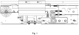
FIG. 1 illustrates a state of a landing door lock under the control of a conventional door operator device. Since asynchronous door vanes will apply the pushing force to the landing door in the door closing direction in advance when the door is closed, when the closing speed of the landing door is smaller than the car door, the landing door hook will lose control and is locked prematurely, and it will collide the fixed hook of the landing door prematurely when the door is closed, which will too quickly consume the initial kinetic energy when the landing door loses control. When there is air pressure at the landing, the sliding block at the bottom of the landing door will squeeze the side wall of the sill under the air pressure, which will increase the friction force at the bottom. When the forced door closing force is smaller than the friction force, it will cause that the landing door cannot be closed normally. - The technical problem to be solved by the present invention is to provide an elevator car door operator device, which can prevent the landing door hook from being locked prematurely when the closing speed of the landing door is smaller than the speed of the car door.
- In order to solve the above technical problem, the present invention discloses an elevator car door operator device, comprising an elevator door operator cross beam, a door vane assembly and a door vane mounting seat, wherein the door vane mounting seat is fixedly arranged on a driving side car door, and the door vane assembly comprises: a first movable vane movably connected onto the door vane mounting seat through a connector; a second movable vane movably connected onto the door vane mounting seat through a connector and fitting with the first movable vane to clamp or loosen a landing door unlocking roller to drive a landing door to move; a first movable vane driving device rotatably connected with the first movable vane and driving the first movable vane to swing towards a direction close to the second movable vane; a protruding part arranged on the first movable vane driving device; a blocking part fixedly arranged on a static part of the elevator door operator cross beam, wherein the blocking part is capable of abutting against the protruding part, limits the swinging range and swinging speed of the first movable vane when the car door is opened, and enables the first movable vane to swing towards a direction far away from the second movable vane when the car door is closed.
- The first movable vane driving device comprises a first swinging rod and a second swinging rod, wherein the first swinging rod comprises: a rotating center rotatably connected with the door vane mounting seat a first end connecting point rotatably connected with the upper part of the first movable vane; and a second end, the protruding part being arranged on the second end; and the second swinging rod comprises: a first end connecting point rotatably connected with the lower part of the first movable vane; and a second end connecting point rotatably connected with the door vane mounting seat, wherein a connecting line between the first end connecting point of the first swinging rod and the first end connecting point of the second swinging rod is always vertical, and a connecting line between the rotating center of the first swinging rod and the second end connecting point is always vertical.
- Preferably, a first limiting device is arranged on the door vane mounting seat, and the first limiting device is used for limiting the distance of movement of the first movable vane towards a car door closing direction.
- Preferably, the first movable vane driving device drives through self-gravity the first movable vane to swing towards a direction close to the second movable vane.
- Preferably, an elastic element pressing plate device is arranged on the second swinging rod, an elastic element guide device is arranged on the door vane mounting seat, the elastic element guide device is connected with one end of an elastic element in a sleeving manner, the other end of the elastic element is connected with the elastic element pressing plate device in a sleeving manner, the elastic element applies a pressing force to the first movable vane through the elastic element pressing plate device to push the first movable vane to swing towards a direction close to the second movable vane, and the elastic element guide device fits with the elastic element pressing plate device to ensure that the first movable vane is always sleeved between the elastic element guide device and the elastic element pressing plate device in the whole swinging process.
- Preferably, the protruding part is a roller.
- Preferably, the protruding part is a fixed shaft.
- Preferably, the blocking part is a cam, and the roller is pressed by the cam against the starting end of the cam line when the car door is fully closed; the first swinging rod rotates when the car door is opened, the cam line of the cam contacts the roller, and the rotating speed of the roller is controlled by the cam line; and the roller is far away from the cam when the first swinging rod stops rotating.
- Preferably, the first limiting device is at least one limiting screw and a contact surface between the limiting screw and the door vane is wrapped with rubber.
- Preferably, the elastic element pressing plate device comprises an elastic element pressing plate mounting plate, a compression spring base and a conical shaft, the pressing plate mounting plate is fixedly connected onto the second swinging rod, the compression spring base is rotatably connected onto the pressing plate mounting plate, and the conical shaft is arranged on the pressing plate mounting plate; the elastic element guide device is a screw, which is fixedly connected onto the door vane mounting seat; and the elastic element is a compression spring, one end of the compression spring sleeves the screw and the other end sleeves the conical shaft.
- Preferably, when the car door is opened, the horizontal displacement direction produced by the protruding part in the rotation process of the first movable vane driving device is the door closing direction.
- Preferably, the door vane assembly further comprises a second movable vane action control device, which drives the second movable vane to swing, and when the car door is normally opened in the unlocking area, the horizontal swinging displacement of the second movable vane towards the door closing direction after the car door is opened is obtained through the following formula: S2=S1-D, where S2 is the horizontal swinging displacement of the second movable vane towards the door closing direction after the car door is opened, S1 is the distance between the working face of the first movable vane and the working face of the second movable vane when the door is fully closed, and D is the horizontal outer width of the landing door unlocking roller and a landing door lock linkage roller.
- Preferably, the door vane assembly further comprises a second movable vane action control device, which drives the second movable vane to swing, when the landing door is opened after the emergency rescue of the car in the unlocking area, the landing door lock linkage roller firstly contacts the second movable vane, the second movable vane is pushed to enable the car door to be opened, the first swinging rod anticlockwise rotates and the first movable vane swings towards the door opening direction, and till the first movable vane swings and touches the landing door lock linkage roller, the horizontal swinging travel of the first movable vane in the door opening direction is: S4=S1-D, where S4 is the horizontal swinging travel of the first movable vane in the door opening direction, S1 is the distance from the working face of the first movable vane to the working face of the second movable vane when the door is fully closed, and D is the horizontal outer width of the landing door unlocking roller and the landing door lock linkage roller.
- Preferably, the elevator car door operator device further comprises a controller, a door motor, a door-in-place switch, a door-in-place switch trigger, a position switch, a position switch trigger, a door switch synchronous belt, a synchronous belt wheel, a synchronous belt tensioning device, a driving side belt suspension arm, a driving side door hanging plate, a driven side belt suspension arm, a driven side door hanging plate, a door guide rail, a door opening limiting device and a door closing limiting device; a door operator driving part, the door guide rail, the synchronous belt wheel and the synchronous belt tensioning device are arranged on the door operator cross beam, and the synchronous belt is wound in the wheel grooves of the output belt wheel of the door motor and the synchronous belt wheel at the other end, and is tensioned by the synchronous belt tensioning device; at the left and right ends of the door center, the driving side belt suspension arm and the driven side belt suspension arm are respectively arranged at the upper and lower positions of the synchronous belt, and the moving direction of the driving side belt suspension arm is enabled to be opposite to the moving direction of the driven side belt suspension arm; the driving side belt suspension arm is connected with the upper part of the driving side door hanging plate, the driven side belt suspension arm is connected with the upper part of the driven side door hanging plate, and the pulleys of the driving side door hanging plate and the driven side door hanging plate roll on the door guide rail; the door-in-place switch is arranged at each door-in-place position of the door operator cross beam, and the door-in-place switch trigger is arranged on each door; the controller controls the door motor to enable the output belt wheel of the door motor to rotate, and the driving side door hanging plate and the driven side door hanging plate open and close the door under the drive of the synchronous belt; and the door-in-place switch is connected to a safety circuit to determine whether the car door is at a closed position, and the position switch is connected to a door control circuit.
- Preferably, when the car door drives the landing door to move together and the car door moves to close, the second movable vane swings towards the door opening direction under the control of the second movable vane action driving device to release the pushing force to the landing door lock linkage roller; the landing door is closed under the effect of a forced door closing force and initial kinetic energy, when the closing speed of the landing door is greater than or equal to the closing speed of the car door, the unlocking roller of the landing door eventually contacts the first movable vane and applies a pushing force to the first movable vane, when the first movable vane is limited by the first limiting device, the speed of the landing door is the same as the speed of the car door, at this time the unlocking roller is always in an unlocked state, and till the landing door is closed, the first movable vane of the car door operator is far away from the unlocking roller, and the landing door unlocking roller rotates towards a locking direction under the effect of its own spring force and gravity, and finally locks the landing door; and when the car door is closed and after the first movable vane and the second movable vane clamp the landing door roller to enable the landing door and the car door to move together, when the speed of the landing door is smaller than the speed of the car door, the first movable vane driving device drives the first movable vane to move towards the door opening direction, the driving force of the first movable vane driving device is greater than the horizontal force of the rotation of the landing door unlocking roller towards the locking direction to prevent the landing door unlocking roller from rotating towards the locking direction, and till the blocking part contacts the protruding part, the first movable vane driving device drives the first movable vane to move towards the door closing direction under the effect of the blocking part such that the landing door unlocking roller rotates towards the locking direction.
- Preferably, at the moment that the car door is opened and the landing door moves together, the travel of the car door is S=P+S5, where S is the travel of the car door, P is the horizontal gap between the first movable vane and the landing door unlocking roller when the car door is fully closed, and S5 is the horizontal unlocking travel of the landing door unlocking roller; and when the car door is closed, when the roller of the first swinging rod contacts the cam, the rest car door travel from the car door to the fully closed position of the car door is smaller than or equal to the travel S of the car door.
- The present invention will be further described below in detail with reference to the drawings and the specific embodiments.
-
FIG. 1 is a state schematic view of a landing door when the landing door moves towards a door closing direction in an unlocked state under the control of the traditional door operator device and when the speed of the landing door is slower than the speed of a car door. -
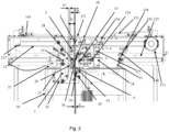
FIG. 2 is a front schematic view of an elevator car door operator device according to the present invention (when a car door is in a fully closed state). -
FIG. 3 is a stereoscopic schematic view of an elevator car door operator device according to the present invention (when a car door is in a fully closed state). -
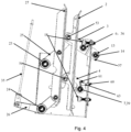
FIG. 4 is a stereoscopic front schematic view of a door vane structure in an elevator car door operator device according to the present invention. -
FIG. 5 is a stereoscopic schematic view of a blocking part inembodiment 1 of an elevator car door operator device according to the present invention. -
FIG. 6 is a stereoscopic schematic view of an elastic element pressing plate device inembodiment 1 of an elevator car door operator device according to the present invention. -
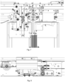
FIG. 7 is a schematic view when a door vane of an elevator car door operator device according to the present invention moves towards a door closing direction in an unlocked state, the speed of a landing door is slower than the speed of a car door and the car door is at a position with a distance of 20mm before the car door is closed. -
FIG. 8 is a schematic view when a landing door lock under the control of an elevator car door operator device according to the present invention moves towards a door closing direction in an unlocked state, the speed of a landing door is slower than the speed of a car door and the car door is at a position with a distance of 20mm before the car door is closed. -
1 Door vane mounting seat 2 First movable vane 3 First swinging rod 4 Second swinging rod 6 Shaft for first swinging rod 7 Shaft for second swinging rod 9 Blocking part 12 Door switch synchronous belt 13 Protruding part 14 Shaft for roller 18 First limiting device 23 Shaft for third swinging rod 24 Shaft for fourth swinging rod 25 Third swinging rod 26 Fourth swinging rod 27 Second movable vane 28 Landing door unlocking roller 29 Landing door lock linkage roller 30 Driving side car door 32 Driving side door hanging plate 33 Driven side door hanging plate 34 Driven side belt wheel suspension arm 35 Second movable vane action control devi ce 36 Rotating center of first swinging rod 39 Second end connecting point of second swinging rod 48 Blocking part bending surface 50 Blocking part cam line 51 Blocking part mounting surface 53 First end connecting point of first swinging rod 54 First end connecting point of second swinging rod 57 Second end of first swinging rod 60 Bolt (elastic element guide device) 61 Elastic element pressing plate device 62 Elastic element pressing plate mounting plate 63 Compression spring (elastic element) 64 Compression spring base 65 Conical shaft 125 Door guide rail 131 Door operator cross beam 132 Door motor 133 Controller 134 Door-in- place switch 135 Door-in- place switch trigger 136 Position switch 137 Synchronous belt wheel 138 Door opening limiting device 139 Door closing limiting device 143 Synchronous belt tensioning device 144 Position switch trigger - As illustrated in
FIG. 2-4 , the elevator car door operator device provided by the present invention comprises a doorvane mounting seat 1, afirst swinging rod 3, asecond swinging rod 4, athird swinging rod 25, afourth swinging rod 26, a firstmovable vane 2, a secondmovable vane 27, a firstlimiting device 18, a second limiting device 20, an elastic element, an elastic element guide device, an elastic element pressingplate device 61, a protrudingpart 13, a blockingpart 9 and a second movable vaneaction control device 35. - The door
vane mounting seat 1 is mounted on a drivingside car door 30. A shaft 6 for the first swinging rod, a shaft 7 for the second swinging rod, ashaft 23 for the third swinging rod and ashaft 24 for the fourth swinging rod are riveted on the doorvane mounting seat 1 in a high-speed spinning manner. A shaft center connecting line between the shaft 6 for the first swinging rod and the shaft 7 for the second swinging rod is vertical. The shaft 6 for the first swinging rod is directly above the shaft 7 for the second swinging rod. The shaft center connecting line between theshaft 23 for the third swinging rod and theshaft 24 for the fourth swinging rod is vertical. Theshaft 23 for the third swinging rod is directly above theshaft 24 for the fourth swinging rod. The shaft 6 for the first swinging rod and theshaft 23 for the third swinging rod have a certain horizontal distance. - The first swinging
rod 3 has a rotatingcenter 36, and a bearing is riveted at the position of the rotatingcenter 36. The end riveted bearing on one side of therotating center 36 is hinged with the upper part of the firstmovable vane 2, and a hole is opened in the fitting position of the upper part of the firstmovable vane 2. A hexagonal bolt may be used as a shaft to fit with the bearing at the hinging point on one side of therotating center 36 of the first swingingrod 3. Aprotruding part 13 is arranged on the first swingingrod 3, and preferably the protruding part is a roller. Ashaft 14 for the roller is riveted on the first swingingrod 3 in a high-speed spinning manner, a bearing is riveted in the roller of the first swinging rod, and the roller is hinged onto theshaft 14 for the roller. A secondend connecting point 39 is arranged on the second swingingrod 4, a bearing is riveted onto the connectingpoint 39, used as the rotating center of the second swingingrod 4 and is hinged with the shaft 7 for the second swinging rod of the doorvane mounting seat 1, the other end of the second swingingrod 4 is riveted with a bearing which is hinged with the lower part of the firstmovable vane 2, a hole is opened in the hinging position of the lower part of the firstmovable vane 2, and a hexagonal bolt is used as a shaft. The firstmovable vane 2 uses a hexagonal bolt as a shaft, and the hexagonal bolt penetrates through the back surface of the first swinging rod, runs through the first swingingrod 3 and the bearing of the first swingingrod 3, and the firstmovable vane 2, and is fixed on the front surface of the first movable vane by using a nut. - As illustrated in
FIG. 5 , the blockingpart 9 on the static part of the elevator door operator cross beam is a steel plate that has been bent for 90 degrees twice. The blockingpart 9 has a blockingpart mounting surface 51 which is mounting with the static part of the elevator door operator cross beam, a blockingpart bending surface 48 which is perpendicular to the blockingpart mounting surface 51, and a third surface which is perpendicular to the blockingpart bending surface 48 and parallel to the blockingpart mounting surface 51. The blockingpart mounting surface 51 and the third surface are not on the same plane, but are parallel to each other. Preferably, the side surface of the third surface is thecam line 50 of the cam. When the car door is opened, when thefirst swinging rod 3 is rotating, the protrudingpart 13 is in contact with the cam line, and the rotation speed is controlled by the cam line. When thefirst swinging rod 3 stops rotating, the protrudingpart 13 is far away from the blockingpart 9. - As illustrated in
FIG. 4 , the doorvane mounting seat 1 is a plate which is bent for 90 degree, the front surface is parallel to the surface of a door plate, and a side surface perpendicular to the front surface is formed by bending on the door closing side. Circular holes with diameter of 9mm are respectively opened in the upper end and the lower end of the side surface, M8 welding nuts are aligned and welded in the centers of the circular holes, and the welding nuts are on the outer side of the door vane mounting seat. M8 bolts wrapped with rubber at the top ends are used, the length of the bolts is 25mm, the bolts are mounted on the M8 welding nuts, and the positions of the bolts are on the inner side of the door vane mounting seat. The bolts on the upper side and the lower side are a first limitingdevice 18. The firstmovable vane 2 has mutually perpendicular surfaces, after the front surface is hinged with thefirst swinging rod 3 and thesecond swinging rod 4, the firstmovable vane 2 is vertical, and when the door is fully closed, the first limiting device is adjusted such that, when the side surface of the first movable vane is in contact with the first limitingdevice 18, the horizontal gap between the firstmovable vane 2 and the outer circle of the upper unlocking roller of the landing door lock is set as C1, which may be generally 9mm. - As illustrated in
FIG. 2-4 , thefirst swinging rod 3, thesecond swinging rod 4 and the firstmovable vane 2 form a double swinging rod mechanism. The gravity of the mechanism enables the firstmovable vane 2 to swing towards the door opening direction. The pressing applied by the blockingpart 9 to the protrudingpart 13 always causes thefirst swinging rod 3 to clockwise rotate with the rotatingcenter 36 as a center, and at this time the firstmovable vane 2 swings towards the door closing direction. When the door is fully closed, the protrudingpart 13 is pressed against by the blockingpart 9, the contact position is the starting end of thecam line 50 of the blockingpart 9, and at this time the firstmovable vane 2 is limited by the first limitingdevice 18 and cannot continuously swing. - As illustrated in
FIG. 6 , one M5 threaded hole is machined in thesecond swinging rod 4, and an elastic element pressingplate device 61 is mounted on the threaded hole. The elastic element pressingplate device 61 comprises an elastic element pressingplate mounting plate 62, acompression spring base 64, and aconical shaft 65. The elastic element pressingplate mounting plate 62 is a steel plate which is bent for 90 degrees and consists of a front surface and a side surface. One circular hole is machined in the front surface. Through the circular hole, the elastic element pressingplate mounting plate 62 is mounted on the M5 threaded hole in thesecond swinging rod 4. A circular hole with diameter of 5 is machined in the side surface of the elastic element pressingplate mounting plate 62, and thecompression spring base 64 is riveted on the circular hole at high speed. Thecompression spring base 64 is a circular surface, and the circular surface is parallel to the side surface of the elastic element pressingplate mounting plate 62. Theconical shaft 65 is arranged on thecompression spring base 64. The center of the conical shaft is concentric with the circle center of thecompression spring base 64. The length of the conical shaft is 5mm. An M5 threaded hole is machined in the side surface of the door vane mounting seat horizontally opposite to the elastic element pressingplate mounting plate 62, an M5 screw is mounted on the threaded hole in the side surface of the door vane mounting seat, and the length of the screw may be within 12mm to 16mm. When the door is fully closed, the angle between the side surface of the elastic element pressingplate mounting plate 62 and the side surface of the doorvane mounting seat 1 may be set to 10 degrees. One end of thecompression spring 63 sleeves the M5 screw, and the other end sleeves the conical shaft to ensure that the firstmovable vane 2 is not separated from theconical shaft 65 and theM5 screw 60 in the whole maximum swinging process. In the working travel of swinging of the firstmovable vane 2, the surface of thecompression spring base 64 of the elastic element pressing plate is always in contact with thecompression spring 63, such that the deformation of thecompression spring 63 accumulates or releases energy. When thecompression spring 63 releases energy, it pushes the firstmovable vane 2 to swing towards the door opening direction, and the firstmovable vane 2 swings towards the door closing direction to enable thecompression spring 63 to accumulate energy. - The car door operator has a full closing holding force, which can be provided by a door motor or other mechanical device. When the door is fully closed, even if the first
movable vane 2 is pushed towards the door opening direction by thecompression spring 63 or the gravity of the mechanism, under the effect of the full closing holding force of the car door, the protrudingpart 13 of the first swinging rod is pressed against by the lower end of the blockingpart 9, and the firstmovable vane 2 cannot swing towards the door opening direction. - As illustrated in
FIG. 7-8 , when the car door is normally opened in the unlocking area, there are a landingdoor unlocking roller 28 and a landing doorlock linkage roller 29 between the firstmovable vane 2 and the secondmovable vane 27. Generally, the outer diameter of the landingdoor unlocking roller 28 and the outer diameter of the landing doorlock linkage roller 29 are the same. Only after the landingdoor unlocking roller 28 swings for a certain distance of unlocking travel, the landing door unlocking roller cannot swing. At this time the centers of the landingdoor unlocking roller 28 and the landing doorlock linkage roller 29 are on the same vertical line. When the car door is opened, as mentioned above, the firstmovable vane 2 swings towards the door opening direction. While the car door is opened, the firstmovable vane 2 swings for a horizontal distance K and then contacts the landingdoor unlocking roller 28 to continuously open the car door. The firstmovable vane 2 continuously swings such that the landingdoor unlocking roller 28 swings towards the landing door lock unlocking direction until the landing door unlocking roller cannot swing. At this time, the centers of the landingdoor unlocking roller 28 and the landing doorlock linkage roller 29 are on the same vertical line. At this time, the acceleration force to push the landing door is far greater than the driving force of the firstmovable vane 2. The driving force of the firstmovable vane 2 is the gravity of the double swinging rod mechanism of the firstmovable vane 2, or the pushing force of thecompression spring 63. When the car door is continuously opened, the firstmovable vane 2 will swing towards the door closing direction by overcoming the driving force under the acceleration reaction force that pushes the landing door. When the car door continuously moves, the firstmovable vane 2 swings and contacts the first limitingdevice 18 under the effect of the reverse pushing force of the landing door, and cannot continuously swing. At this time, it can be defined that the door opening travel of the car door is S. At this time, the acceleration force to push the landing door is provided by the first limitingdevice 18, and the car door and the landing door start to move together. - After the car door is opened, the second
movable vane 27 starts to swing towards the door closing direction under the effect of the second movable vaneaction driving device 35. The second movable vaneaction driving device 35 enables the horizontal swinging displacement of the secondmovable vane 27 towards the door closing direction after the car door is opened to be S2: S2 = S1-D. - In the above formula, S1 is the distance between the working face of the first
movable vane 2 and the working face of the secondmovable vane 27 when the door is fully closed, D is the horizontal outer width of the landingdoor unlocking roller 28 and the landing doorlock linkage roller 29, and generally in the existing technology, D is the outer diameter of the landing door unlocking roller or the landing door lock linkage roller. - In the actual design, according to the above settings, when the car door is fully closed, the horizontal gap P between the working face of the first
movable vane 2 and the outer circle of the upper roller of the landing door lock is 9mm. Through the design of the blockingpart 9, the design of thefirst swinging rod 3, the position relationship between the firstrotating center 36 and the firstmovable vane 2 on thefirst swinging rod 3, the position relationship between the protrudingpart 13 on thefirst swinging rod 3 and therotating center 36 of the first swinging rod, and the position relationship between the blockingpart 9 and therotating center 36 of the first swinging rod, the unlocking linkage process of the car door and the landing door in the unlocking area is as follows: - When the car door travel is 4mm, the horizontal travel of the horizontal swinging of the first
movable vane 2 is 5mm, and the working face of the firstmovable vane 2 just contacts the outer circle of the landingdoor unlocking roller 28. - When the car door travel is 7mm, the horizontal travel of the horizontal swinging of the first
movable vane 2 is 9mm, and the firstmovable vane 2 enables the outer circle of the landingdoor unlocking roller 28 to rotate to a position at which the unlocking travel is the maximum. At this time, the centers of the landingdoor unlocking roller 28 and the landing doorlock linkage roller 29 are on the same vertical line, and the upper roller of the landing door lock cannot continuously rotate. At this time, the reaction force of the acceleration force of the landing door is greater than the sum of the gravity of the first movable vane mechanism and the force in the horizontal direction of the pressing force of thecompression spring 63. When the car door is continuously opened, the firstmovable vane 2 starts to swing towards the door closing direction. - When the car door travel is 16mm, the first
movable vane 2 has rotated towards the door closing direction and has contacted the first limitingdevice 18, the horizontal displacement of the firstmovable vane 2 compared with the original one is also 16mm, and then the car door and the landing door are opened and closed in a linked manner. In the opening process of the car door, the secondmovable vane 27 continuously swings towards the door closing direction under the control of the second movable vaneaction control device 35, the final horizontal swinging travel is S1-D, and thus the upper and lower rollers of the landing door are clamped. - When the car is in the unlocking area and requires for emergency rescue, a triangular key is used to open the landing door. When the landing door is opened, the landing door
lock linkage roller 29 firstly contacts the secondmovable vane 27, and the secondmovable vane 27 is subjected to the pushing force such that the car door is opened. When the car door is opened, thefirst swinging rod 3 anticlockwise rotates, and the firstmovable vane 2 swings towards the door opening direction. When the firstmovable vane 2 swings until it contacts the landing doorlock linkage roller 29, - the horizontal travel of the swinging of the first
movable vane 2 towards the door opening direction is S4: S4=S1-D. - In the above formula, S1 is the distance between the working face of the first
movable vane 2 and the working face of the secondmovable vane 27 when the door is fully closed, S1 is 72mm here, and D is the horizontal outer width of the landing door unlocking roller and the landing door lock linkage roller. - When the car is in the unlocking area, the car door drives the landing door to move together. When the door is closed, the second
movable vane 27 swings towards the door opening direction under the control of the second movable vaneaction driving device 35 to release the pushing force to the landing door lock linkage roller. In the existing technology, the secondmovable vane 27 generally releases the pushing force to the landing door lock linkage roller when the car door is at a position with a distance of about 90mm before the door is closed, and the landing door is closed under the effect of the forced door closing force and the initial kinetic energy. Two situations may occur when the door is closed later: - In the first situation, the door closing speed of the landing door is always greater than or equal to the door closing speed of the car door, and the landing
door unlocking roller 28 will finally contact the firstmovable vane 2 and apply a pressing force to the firstmovable vane 2. When the firstmovable vane 2 is limited by the first limitingdevice 18, the speed of the landing door and the speed of the car door are the same, the unlocking roller is always in the unlocked state until the landing door is closed, the firstmovable vane 2 of the car door operator is far away from the unlockingroller 28, and the landing door unlocking roller rotates towards the locking direction under the effect of its own spring force and gravity, and finally locks the landing door. - In the second situation, the door closing speed of the landing door is smaller than the door closing speed of the car door. At this time, the landing door unlocking roller has a trend of being far away from the first
movable vane 2. At this time, the firstmovable vane 2 rotates towards the door opening direction under the effect of the gravity of the double swinging rod mechanism or thecompression spring 63. The horizontal pushing force produced by thecompression spring 63 to the firstmovable vane 2 in the door opening direction should be greater than the horizontal force produced by the landingdoor unlocking roller 28 during rotation towards the locking direction. The landingdoor unlocking roller 28 cannot rotate towards the locking direction under the push of the firstmovable vane 2. Till the protrudingpart 13 of thefirst swinging rod 3 contacts the blockingpart 9, thefirst swinging rod 3 enables the firstmovable vane 2 to rotate towards the door closing direction under the reverse pushing force of the blockingpart 9. At this time, the landingdoor unlocking roller 28 starts to rotate towards the locking direction. - According to the above moment that the car door is opened and the landing door moves together, the travel of the car door S=P+S5=16mm.
- P is the horizontal gap between the first
movable vane 2 and the landing door unlocking roller when the car door is fully closed, which is 9mm. - S5 is the horizontal travel of the unlocking of the landing door unlocking roller, which is 7mm.
- When the car door is closed and the protruding
part 13 of thefirst swinging rod 3 contacts the blockingpart 9, the rest of the car door travel from the car door to the fully closed position of the car door is smaller than or equal to S, which is obtained through the following design: - (1) The shape of the cam line of the blocking
part 9 and the position relationship between the blockingpart 9 and thefirst swinging rod 3. - (2) The leverage ratio of the
first swinging rod 3 and the outer diameter of the protrudingpart 13. The leverage ratio is the ratio of the distance from the center of the protrudingpart 13 to the rotating center to the distance from the hinging point of the firstmovable vane 2 to the rotating center. - (3) The relationship between the horizontal travel of swinging of the second
movable vane 2 and the travel of the car door. - Through the above design, the unlocked state of the landing door lock is controlled. When the car door opening travel S or the pre-closing travel S is maintained, the landing door lock is in the unlocked state, so as to prevent the hook of the landing door lock from falling prematurely and the fixed hook of the landing door lock from hitting prematurely.
- As illustrated in
FIG. 1-7 , the elevator car door operator device provided by the present invention further comprises a controller 133, a door motor 132, a door-in-place switch 134, a door-in-place switch trigger 135, a position switch 136, a position switch trigger 144, a door switch synchronous belt 12, a synchronous belt wheel 137, a synchronous belt tensioning device 143, a driving side belt suspension arm, a driving side door hanging plate 32, a driven side belt suspension arm 34, a driven side door hanging plate 33, a door guide rail 125 , a door opening limiting device 138, a door closing limiting device 139; the door operator driving part, the door guide rail 125, the synchronous belt wheel 137 and the synchronous belt tensioning device 143 are arranged on a door operator cross beam 131, and the synchronous belt 12 is wound in the wheel grooves of the output belt wheel of the door motor and the synchronous belt wheel 137 at the other end, and is tensioned by a synchronous belt tensioning device 143; at the left and right ends of the door center, the driving side belt suspension arm and the driven side belt suspension arm 34 are respectively arranged at the upper and lower positions of the synchronous belt 12, and the moving direction of the driving side belt suspension arm is enabled to be opposite to the moving direction of the driven side belt suspension arm 34; the driving side belt suspension arm is connected with the upper part of the driving side door hanging plate 32, the driven side belt suspension arm 34 is connected with the upper part of the driven side door hanging plate 33, and the pulleys of the driving side door hanging plate 32 and the driven side door hanging plate 33 roll on the door guide rail 125; the door-in-place switch 134 is arranged at each door-in-place position of the door operator cross beam 131, and the door-in-place switch trigger 144 is arranged on each door; the controller 133 controls the door motor 132 to enable the output belt wheel of the door motor 132 to rotate, and the driving side door hanging plate 32 and the driven side door hanging plate 33 open and close the door under the drive of the synchronous belt 12; and the door-in-place switch 134 is connected to a safety circuit to determine whether the car door is at a closed position, and the position switch 136 is connected to a door control circuit.
Claims (14)
- An elevator car door operator device, comprising an elevator door operator cross beam (131), a door vane assembly and a door vane mounting seat (1), wherein the door vane mounting seat (1) is fixedly arranged on a driving side car door, and the door vane assembly comprises:a first movable vane (2) movably connected onto the door vane mounting seat (1) through a connector;a second movable vane (27) movably connected onto the door vane mounting seat (1) through a connector and fitting with the first movable vane to clamp or loosen a landing door unlocking roller to drive a landing door to move;a first movable vane driving device (31) rotatably connected with the first movable vane (2) and driving the first movable vane (2) to swing towards a direction close to the second movable vane (27);a protruding part (13) arranged on the first movable vane driving device;a blocking part (9) fixedly arranged on a static part of the elevator door operator cross beam, whereinthe blocking part (9) fits with the protruding part (13) to limit the swinging range and swinging speed of the first movable vane (2) when the car door is opened, and the blocking part (9) fits with the protruding part (13) to enable the first movable vane (2) to swing towards a direction far away from the second movable vane (27) when the car door is closed, characterized in that the first movable vane driving device comprises a first swinging rod (3) and a second swinging rod (4), whereinthe first swinging rod (3) comprises:a rotating center (36) rotatably connected with the door vane mounting seat (1);a first end connecting point (53) rotatably connected with the upper part of the first movable vane; anda second end (57), the protruding part (13) being arranged on the second end; andthe second swinging rod comprises:a first end connecting point (54) rotatably connected with the lower part of the first movable vane; anda second end connecting point (39) rotatably connected with the door vane mounting seat (1), wherein a connecting line between the first end connecting point of the first swinging rod and the first end connecting point of the second swinging rod is always vertical, and a connecting line between the rotating center (36) of the first swinging rod and the second end connecting point is always vertical.
- The elevator car door operator device according to claim 1, wherein a first limiting device is arranged on the door vane mounting seat (1), and the first limiting device is used for limiting the distance of movement of the first movable vane (2) towards a car door closing direction.
- The elevator car door operator device according to claim 2, wherein the first movable vane driving device (21) drives through self-gravity the first movable vane to swing towards a direction close to the second movable vane.
- The elevator car door operator device according to claim 2, wherein an elastic element pressing plate device (61) is arranged on the second swinging rod, an elastic element guide device is arranged on the door vane mounting seat (1), the elastic element guide device is connected with one end of an elastic element in a sleeving manner, and the other end of the elastic element is connected with the elastic element pressing plate device (61) in a sleeving manner;the elastic element applies a pressing force to the first movable vane (2) through the elastic element pressing plate device (61) to push the first movable vane (2) to swing towards a direction close to the second movable vane (27); andthe elastic element guide device fits with the elastic element pressing plate device to ensure that the first movable vane (2) is always sleeved between the elastic element guide device and the elastic element pressing plate device (61) in the whole swinging process.
- The elevator car door operator device according to claim 3, wherein the protruding part (13) is a roller or a fixed shaft.
- The elevator car door operator device according to claim 5, wherein the blocking part (9) is a cam, and the roller is pressed by the cam against the starting end of the cam line when the car door is fully closed; the first swinging rod rotates when the car door is opened, the cam line of the cam contacts the roller, and the rotating speed of the roller is controlled by the cam line; and the roller is far away from the cam when the first swinging rod stops rotating.
- The elevator car door operator device according to claim 3, wherein the first limiting device is at least one limiting screw and a contact surface between the limiting screw and the door vane is wrapped with rubber.
- The elevator car door operator device according to claim 3, whereinthe elastic element pressing plate device (61) comprises an elastic element pressing plate mounting plate (62), a compression spring base (64) and a conical shaft (65), the pressing plate mounting plate (62) is fixedly connected onto the second swinging rod (4), the compression spring base (64) is rotatably connected onto the pressing plate mounting plate (62), and the conical shaft (65) is arranged on the pressing plate mounting plate (62);the elastic element guide device is a screw (60), which is fixedly connected onto the door vane mounting seat (1); andthe elastic element is a compression spring (63), one end of the compression spring (63) sleeves the screw (60) and the other end sleeves the conical shaft (65).
- The elevator car door operator device according to any one of claims 3-7, wherein when the car door is opened, the horizontal displacement direction produced by the protruding part (13) in the rotation process of the first movable vane driving device is the door closing direction.
- The elevator car door operator device according to any one of claims 3-7, wherein the door vane assembly further comprises a second movable vane action control device (35), which drives the second movable vane (27) to swing, and when the car door is normally opened in the unlocking area, the horizontal swinging displacement of the second movable vane (27) towards the door closing direction after the car door is opened is obtained through the following formula:

- The elevator car door operator device according to any one of claims 3-7, wherein the door vane assembly further comprises a second movable vane action control device (35), which drives the second movable vane (27) to swing, when the landing door is opened after the emergency rescue of the car in the unlocking area, a landing door lock linkage roller (29) firstly contacts the second movable vane (27), the second movable vane (27) is pushed to enable the car door to be opened, the first swinging rod (3) anticlockwise rotates and the first movable vane (27) swings towards the door opening direction, and till the first movable vane (2) swings and touches the landing door lock linkage roller (29), the horizontal swinging travel of the first movable vane (2) in the door opening direction is:

- The elevator car door operator device according to any one of claims 3-7, wherein the elevator car door operator device further comprises a controller (133), a door motor (132), a door-in-place switch (134), a door-in-place switch trigger (135), a position switch (136), a position switch trigger (144), a door switch synchronous belt (12), a synchronous belt wheel (137), a synchronous belt tensioning device (143), a driving side belt suspension arm, a driving side door hanging plate (32), a driven side belt suspension arm (34), a driven side door hanging plate (33), a door guide rail (125), a door opening limiting device (138) and a door closing limiting device (139);a door operator driving part, the door guide rail (125), the synchronous belt wheel (137) and the synchronous belt tensioning device (143) are arranged on the door operator cross beam (131), and the synchronous belt (12) is wound in the wheel grooves of the output belt wheel of the door motor and the synchronous belt wheel (137) at the other end, and is tensioned by the synchronous belt tensioning device (143);at the left and right ends of the door center, the driving side belt suspension arm and the driven side belt suspension arm (34) are respectively arranged at the upper and lower positions of the synchronous belt (12), and the moving direction of the driving side belt suspension arm is enabled to be opposite to the moving direction of the driven side belt suspension arm (34);the driving side belt suspension arm is connected with the upper part of the driving side door hanging plate (32), the driven side belt suspension arm (34) is connected with the upper part of the driven side door hanging plate (33), and the pulleys of the driving side door hanging plate (32) and the driven side door hanging plate (33) roll on the door guide rail (125); the door-in-place switch (134) is arranged at each door-in-place position of the door operator cross beam (131), and the door-in-place switch trigger (144) is arranged on each door;the controller (133) controls the door motor (132) to enable the output belt wheel of the door motor (132) to rotate, and the driving side door hanging plate (32) and the driven side door hanging plate (33) open and close the door under the drive of the synchronous belt (12); andthe door-in-place switch (134) is connected to a safety circuit to determine whether the car door is at a closed position, and the position switch (136) is connected to a door control circuit.
- The elevator car door operator device according to any one of claims 3-7, wherein when the car door drives the landing door to move together and the car door moves to close, the second movable vane (27) swings towards the door opening direction under the control of the second movable vane action driving device (35) to release the pushing force to the landing door lock linkage roller;the landing door is closed under the effect of a forced door closing force and initial kinetic energy, when the closing speed of the landing door is greater than or equal to the closing speed of the car door, the unlocking roller (28) of the landing door eventually contacts the first movable vane (2) and applies a pushing force to the first movable vane (2), when the first movable vane (2) is limited by the first limiting device (18), the speed of the landing door is the same as the speed of the car door, at this time the unlocking roller is always in an unlocked state, and till the landing door is closed, the first movable vane (2) of the car door operator is far away from the unlocking roller (28), and the landing door unlocking roller rotates towards a locking direction under the effect of its own spring force and gravity, and finally locks the landing door; andwhen the car door is closed and after the first movable vane (2) and the second movable vane (27) clamp the landing door roller to enable the landing door and the car door to move together, when the speed of the landing door is smaller than the speed of the car door, the first movable vane driving device drives the first movable vane (2) to move towards the door opening direction, the driving force of the first movable vane driving device is greater than the horizontal force of the rotation of the landing door unlocking roller towards the locking direction to prevent the landing door unlocking roller from rotating towards the locking direction, and till the blocking part (9) contacts the protruding part (13), the first movable vane driving device drives the first movable vane (2) to move towards the door closing direction under the effect of the blocking part (9) such that the landing door unlocking roller rotates towards the locking direction.
- The elevator car door operator device according to any one of claims 3-7, wherein at the moment that the car door is opened and the landing door moves together, the travel of the car door is S=P+S5,where S is the travel of the car door, P is the horizontal gap between the first movable vane (2) and the landing door unlocking roller when the car door is fully closed, and S5 is the horizontal unlocking travel of the landing door unlocking roller; andwhen the car door is closed, when the roller (13) of the first swinging rod (3) contacts the cam (9), the rest car door travel from the car door to the fully closed position of the car door is smaller than or equal to the travel S of the car door.
Applications Claiming Priority (2)
| Application Number | Priority Date | Filing Date | Title |
|---|---|---|---|
| CN201711029437.8A CN109720972B (en) | 2017-10-27 | 2017-10-27 | Elevator cage door machine device |
| PCT/CN2018/098652 WO2019080583A1 (en) | 2017-10-27 | 2018-08-03 | Elevator car door machine device |
Publications (3)
| Publication Number | Publication Date |
|---|---|
| EP3659957A1 EP3659957A1 (en) | 2020-06-03 |
| EP3659957A4 EP3659957A4 (en) | 2021-04-21 |
| EP3659957B1 true EP3659957B1 (en) | 2023-11-15 |
Family
ID=66246789
Family Applications (1)
| Application Number | Title | Priority Date | Filing Date |
|---|---|---|---|
| EP18871254.1A Active EP3659957B1 (en) | 2017-10-27 | 2018-08-03 | Elevator car door operator device |
Country Status (5)
| Country | Link |
|---|---|
| EP (1) | EP3659957B1 (en) |
| JP (1) | JP7027533B2 (en) |
| KR (1) | KR102321041B1 (en) |
| CN (1) | CN109720972B (en) |
| WO (1) | WO2019080583A1 (en) |
Families Citing this family (4)
| Publication number | Priority date | Publication date | Assignee | Title |
|---|---|---|---|---|
| CN113860126B (en) * | 2021-09-28 | 2023-10-31 | 苏州富士精工电梯有限公司 | Umbrella-shaped principle round door machine |
| DE102021134388A1 (en) | 2021-12-22 | 2023-06-22 | Meiller Aufzugtüren GmbH | carrier system |
| CN114608858B (en) * | 2022-05-12 | 2022-08-12 | 天津市特种设备监督检验技术研究院(天津市特种设备事故应急调查处理中心) | Elevator door strength inspection equipment |
| CN116081436B (en) * | 2023-04-07 | 2023-06-16 | 沈阳华彩机械制造有限公司 | Locking and dragging device of arc door machine |
Citations (1)
| Publication number | Priority date | Publication date | Assignee | Title |
|---|---|---|---|---|
| EP0763496A1 (en) * | 1995-09-13 | 1997-03-19 | Kone Oy | Procedure for closing an elevator landing door, and a door coupler |
Family Cites Families (26)
| Publication number | Priority date | Publication date | Assignee | Title |
|---|---|---|---|---|
| JPH02310283A (en) * | 1989-05-26 | 1990-12-26 | Mitsubishi Electric Corp | One-sheet door up-opening dumb waiter |
| JP4879477B2 (en) * | 2003-12-08 | 2012-02-22 | インベンテイオ・アクテイエンゲゼルシヤフト | Elevator door drive device |
| CN100503412C (en) * | 2003-12-18 | 2009-06-24 | 上海三菱电梯有限公司 | Elevator cage door lock device |
| WO2005092772A1 (en) * | 2004-03-22 | 2005-10-06 | Otis Elevator Company | Coupling device for elevator car doors and landing doors |
| JP4544887B2 (en) * | 2004-03-26 | 2010-09-15 | 東芝エレベータ株式会社 | Elevator door device |
| CN100572251C (en) * | 2006-07-17 | 2009-12-23 | 上海三菱电梯有限公司 | Elevator cage door machine device |
| CN101081677B (en) * | 2007-04-17 | 2010-12-29 | 宁波申菱电梯配件有限公司 | Elevator car door locking device |
| JP5448306B2 (en) | 2007-06-06 | 2014-03-19 | 日本オーチス・エレベータ株式会社 | Elevator car side door locking device |
| JP2009166956A (en) | 2008-01-16 | 2009-07-30 | Toshiba Elevator Co Ltd | Elevator door device |
| JP5484479B2 (en) * | 2009-10-09 | 2014-05-07 | 三菱電機株式会社 | Elevator door engagement device |
| CN102107812B (en) * | 2009-12-24 | 2013-04-03 | 上海三菱电梯有限公司 | Elevator door lock |
| JP2013018559A (en) * | 2011-07-07 | 2013-01-31 | Toshiba Elevator Co Ltd | Door device for elevator |
| JP2013119476A (en) * | 2011-12-08 | 2013-06-17 | Mitsubishi Electric Building Techno Service Co Ltd | Elevator door device |
| CN103387173B (en) * | 2012-05-09 | 2015-08-19 | 上海三菱电梯有限公司 | Elevator car door locking device |
| DE112013007252B4 (en) | 2013-07-19 | 2021-03-04 | Mitsubishi Electric Corporation | Elevator car door locking device |
| CN104418218B (en) * | 2013-08-27 | 2016-06-15 | 上海三菱电梯有限公司 | Elevator landing door |
| CN104773638B (en) * | 2014-01-15 | 2016-06-22 | 上海三菱电梯有限公司 | With the asynchronous door cutter of car door lock, elevator door-motor and gate system |
| CN104773637B (en) * | 2014-01-15 | 2016-06-15 | 上海三菱电梯有限公司 | With the asynchronous door cutter of car door lock, elevator door-motor and gate system |
| CN104773636B (en) * | 2014-01-15 | 2016-06-15 | 上海三菱电梯有限公司 | With the asynchronous door cutter of car door lock, elevator door-motor and gate system |
| DE202014102533U1 (en) * | 2014-05-13 | 2015-08-20 | Wittur Holding Gmbh | Door coupler with an operation enabling its flexible positioning |
| US10207900B2 (en) | 2014-10-15 | 2019-02-19 | Mitsubishi Electric Corporation | Elevator car door apparatus |
| CN204434039U (en) * | 2015-01-12 | 2015-07-01 | 三菱电机上海机电电梯有限公司 | The synchronous door knife mechanism of elevator |
| CN204958087U (en) * | 2015-09-14 | 2016-01-13 | 宁波欣达电梯配件厂 | Door gear is prevented taking off by elevator |
| CN205312842U (en) * | 2015-12-09 | 2016-06-15 | 上海三菱电梯有限公司 | Rotation triggers formula layer every lock lock core device and door unblock of elevator layer and warning device |
| CN106744214B (en) * | 2017-03-29 | 2019-09-13 | 日立电梯(中国)有限公司 | A kind of band opens the layer door of defencive function |
| CN107150942B (en) * | 2017-06-26 | 2023-03-31 | 上海贝思特门机有限公司 | Double-locking type anti-theft car door lock and door knife device |
-
2017
- 2017-10-27 CN CN201711029437.8A patent/CN109720972B/en active Active
-
2018
- 2018-08-03 JP JP2020514996A patent/JP7027533B2/en active Active
- 2018-08-03 KR KR1020207000094A patent/KR102321041B1/en active IP Right Grant
- 2018-08-03 WO PCT/CN2018/098652 patent/WO2019080583A1/en unknown
- 2018-08-03 EP EP18871254.1A patent/EP3659957B1/en active Active
Patent Citations (1)
| Publication number | Priority date | Publication date | Assignee | Title |
|---|---|---|---|---|
| EP0763496A1 (en) * | 1995-09-13 | 1997-03-19 | Kone Oy | Procedure for closing an elevator landing door, and a door coupler |
Also Published As
| Publication number | Publication date |
|---|---|
| KR20200016329A (en) | 2020-02-14 |
| JP2020533251A (en) | 2020-11-19 |
| CN109720972B (en) | 2020-05-01 |
| JP7027533B2 (en) | 2022-03-01 |
| EP3659957A1 (en) | 2020-06-03 |
| KR102321041B1 (en) | 2021-11-04 |
| WO2019080583A1 (en) | 2019-05-02 |
| CN109720972A (en) | 2019-05-07 |
| EP3659957A4 (en) | 2021-04-21 |
Similar Documents
| Publication | Publication Date | Title |
|---|---|---|
| EP3659957B1 (en) | Elevator car door operator device | |
| EP3659956B1 (en) | Elevator car door machine device having car door lock | |
| CN105645239B (en) | Synchronous locking mechanism of elevator door motor and operation method thereof | |
| WO2018166405A1 (en) | Elevator door lock device | |
| CN107973200B (en) | Elevator anti-theft car door locking knife device and elevator | |
| WO2016119484A1 (en) | Elevator synchronous door vane device with a retaining assembly | |
| JP2010515844A (en) | Door door drive device | |
| WO2017124580A1 (en) | Double sliding-plug door system | |
| WO2016041520A1 (en) | Operating mechanism and locking device thereof | |
| KR102058734B1 (en) | Screw Drive Control System | |
| JP2010515843A (en) | Door closing device | |
| JP4021647B2 (en) | Elevator door opening and closing device | |
| CN108502687B (en) | Elevator car door lock assembly | |
| KR20050105440A (en) | Pivoting sliding door for vehicles | |
| CA2682514A1 (en) | An electro-mechanical door lock having a reduced power requirement | |
| JP2020533251A5 (en) | ||
| EP3228575A1 (en) | Door assembly of a lift with lock | |
| CN112638813B (en) | Elevator car door device | |
| CN106976792B (en) | Asynchronous door knife | |
| CN113233295B (en) | Car door opening and closing control mechanism, hall door opening and closing control mechanism and door system | |
| CN109881977B (en) | Door lock using clutch | |
| JPH0624244A (en) | Lock device for window | |
| JPH0611341Y2 (en) | Door opening / closing mechanism | |
| CN205367565U (en) | Lock dish ware | |
| CN113173185B (en) | Locking device and front end opening and closing mechanism |
Legal Events
| Date | Code | Title | Description |
|---|---|---|---|
| STAA | Information on the status of an ep patent application or granted ep patent |
Free format text: STATUS: THE INTERNATIONAL PUBLICATION HAS BEEN MADE |
|
| PUAI | Public reference made under article 153(3) epc to a published international application that has entered the european phase |
Free format text: ORIGINAL CODE: 0009012 |
|
| STAA | Information on the status of an ep patent application or granted ep patent |
Free format text: STATUS: REQUEST FOR EXAMINATION WAS MADE |
|
| 17P | Request for examination filed |
Effective date: 20200224 |
|
| AK | Designated contracting states |
Kind code of ref document: A1 Designated state(s): AL AT BE BG CH CY CZ DE DK EE ES FI FR GB GR HR HU IE IS IT LI LT LU LV MC MK MT NL NO PL PT RO RS SE SI SK SM TR |
|
| AX | Request for extension of the european patent |
Extension state: BA ME |
|
| DAV | Request for validation of the european patent (deleted) | ||
| DAX | Request for extension of the european patent (deleted) | ||
| REG | Reference to a national code |
Ref country code: DE Ref legal event code: R079 Ref document number: 602018061271 Country of ref document: DE Free format text: PREVIOUS MAIN CLASS: B66B0013200000 Ipc: B66B0013120000 Ref country code: DE Free format text: PREVIOUS MAIN CLASS: B66B0013200000 Ipc: B66B0013120000 |
|
| A4 | Supplementary search report drawn up and despatched |
Effective date: 20210318 |
|
| RIC1 | Information provided on ipc code assigned before grant |
Ipc: B66B 13/12 20060101AFI20210312BHEP Ipc: B66B 13/20 20060101ALI20210312BHEP |
|
| GRAP | Despatch of communication of intention to grant a patent |
Free format text: ORIGINAL CODE: EPIDOSNIGR1 |
|
| STAA | Information on the status of an ep patent application or granted ep patent |
Free format text: STATUS: GRANT OF PATENT IS INTENDED |
|
| INTG | Intention to grant announced |
Effective date: 20230809 |
|
| GRAS | Grant fee paid |
Free format text: ORIGINAL CODE: EPIDOSNIGR3 |
|
| GRAA | (expected) grant |
Free format text: ORIGINAL CODE: 0009210 |
|
| STAA | Information on the status of an ep patent application or granted ep patent |
Free format text: STATUS: THE PATENT HAS BEEN GRANTED |
|
| AK | Designated contracting states |
Kind code of ref document: B1 Designated state(s): AL AT BE BG CH CY CZ DE DK EE ES FI FR GB GR HR HU IE IS IT LI LT LU LV MC MK MT NL NO PL PT RO RS SE SI SK SM TR |
|
| REG | Reference to a national code |
Ref country code: CH Ref legal event code: EP Ref country code: GB Ref legal event code: FG4D |
|
| REG | Reference to a national code |
Ref country code: DE Ref legal event code: R096 Ref document number: 602018061271 Country of ref document: DE |
|
| REG | Reference to a national code |
Ref country code: IE Ref legal event code: FG4D |
|
| REG | Reference to a national code |
Ref country code: LT Ref legal event code: MG9D |
|
| REG | Reference to a national code |
Ref country code: NL Ref legal event code: MP Effective date: 20231115 |
|
| PG25 | Lapsed in a contracting state [announced via postgrant information from national office to epo] |
Ref country code: GR Free format text: LAPSE BECAUSE OF FAILURE TO SUBMIT A TRANSLATION OF THE DESCRIPTION OR TO PAY THE FEE WITHIN THE PRESCRIBED TIME-LIMIT Effective date: 20240216 |
|
| PG25 | Lapsed in a contracting state [announced via postgrant information from national office to epo] |
Ref country code: IS Free format text: LAPSE BECAUSE OF FAILURE TO SUBMIT A TRANSLATION OF THE DESCRIPTION OR TO PAY THE FEE WITHIN THE PRESCRIBED TIME-LIMIT Effective date: 20240315 |
|
| PG25 | Lapsed in a contracting state [announced via postgrant information from national office to epo] |
Ref country code: LT Free format text: LAPSE BECAUSE OF FAILURE TO SUBMIT A TRANSLATION OF THE DESCRIPTION OR TO PAY THE FEE WITHIN THE PRESCRIBED TIME-LIMIT Effective date: 20231115 |
|
| REG | Reference to a national code |
Ref country code: AT Ref legal event code: MK05 Ref document number: 1631606 Country of ref document: AT Kind code of ref document: T Effective date: 20231115 |
|
| PG25 | Lapsed in a contracting state [announced via postgrant information from national office to epo] |
Ref country code: NL Free format text: LAPSE BECAUSE OF FAILURE TO SUBMIT A TRANSLATION OF THE DESCRIPTION OR TO PAY THE FEE WITHIN THE PRESCRIBED TIME-LIMIT Effective date: 20231115 |