EP3659941A1 - Intermediate bulk container - Google Patents
Intermediate bulk container Download PDFInfo
- Publication number
- EP3659941A1 EP3659941A1 EP18209534.9A EP18209534A EP3659941A1 EP 3659941 A1 EP3659941 A1 EP 3659941A1 EP 18209534 A EP18209534 A EP 18209534A EP 3659941 A1 EP3659941 A1 EP 3659941A1
- Authority
- EP
- European Patent Office
- Prior art keywords
- container
- tank
- support structure
- base
- columns
- Prior art date
- Legal status (The legal status is an assumption and is not a legal conclusion. Google has not performed a legal analysis and makes no representation as to the accuracy of the status listed.)
- Granted
Links
Images





Classifications
-
- B—PERFORMING OPERATIONS; TRANSPORTING
- B65—CONVEYING; PACKING; STORING; HANDLING THIN OR FILAMENTARY MATERIAL
- B65D—CONTAINERS FOR STORAGE OR TRANSPORT OF ARTICLES OR MATERIALS, e.g. BAGS, BARRELS, BOTTLES, BOXES, CANS, CARTONS, CRATES, DRUMS, JARS, TANKS, HOPPERS, FORWARDING CONTAINERS; ACCESSORIES, CLOSURES, OR FITTINGS THEREFOR; PACKAGING ELEMENTS; PACKAGES
- B65D90/00—Component parts, details or accessories for large containers
- B65D90/12—Supports
- B65D90/20—Frames or nets, e.g. for flexible containers
-
- B—PERFORMING OPERATIONS; TRANSPORTING
- B65—CONVEYING; PACKING; STORING; HANDLING THIN OR FILAMENTARY MATERIAL
- B65D—CONTAINERS FOR STORAGE OR TRANSPORT OF ARTICLES OR MATERIALS, e.g. BAGS, BARRELS, BOTTLES, BOXES, CANS, CARTONS, CRATES, DRUMS, JARS, TANKS, HOPPERS, FORWARDING CONTAINERS; ACCESSORIES, CLOSURES, OR FITTINGS THEREFOR; PACKAGING ELEMENTS; PACKAGES
- B65D77/00—Packages formed by enclosing articles or materials in preformed containers, e.g. boxes, cartons, sacks or bags
- B65D77/04—Articles or materials enclosed in two or more containers disposed one within another
- B65D77/0446—Articles or materials enclosed in two or more containers disposed one within another the inner and outer containers being rigid or semi-rigid and the outer container being of polygonal cross-section not formed by folding or erecting one or more blanks
- B65D77/0453—Articles or materials enclosed in two or more containers disposed one within another the inner and outer containers being rigid or semi-rigid and the outer container being of polygonal cross-section not formed by folding or erecting one or more blanks the inner container having a polygonal cross-section
- B65D77/0466—Articles or materials enclosed in two or more containers disposed one within another the inner and outer containers being rigid or semi-rigid and the outer container being of polygonal cross-section not formed by folding or erecting one or more blanks the inner container having a polygonal cross-section the containers being mounted on a pallet
-
- B—PERFORMING OPERATIONS; TRANSPORTING
- B65—CONVEYING; PACKING; STORING; HANDLING THIN OR FILAMENTARY MATERIAL
- B65D—CONTAINERS FOR STORAGE OR TRANSPORT OF ARTICLES OR MATERIALS, e.g. BAGS, BARRELS, BOTTLES, BOXES, CANS, CARTONS, CRATES, DRUMS, JARS, TANKS, HOPPERS, FORWARDING CONTAINERS; ACCESSORIES, CLOSURES, OR FITTINGS THEREFOR; PACKAGING ELEMENTS; PACKAGES
- B65D19/00—Pallets or like platforms, with or without side walls, for supporting loads to be lifted or lowered
- B65D19/02—Rigid pallets with side walls, e.g. box pallets
- B65D19/06—Rigid pallets with side walls, e.g. box pallets with bodies formed by uniting or interconnecting two or more components
- B65D19/18—Rigid pallets with side walls, e.g. box pallets with bodies formed by uniting or interconnecting two or more components made wholly or mainly of plastics material
-
- B—PERFORMING OPERATIONS; TRANSPORTING
- B65—CONVEYING; PACKING; STORING; HANDLING THIN OR FILAMENTARY MATERIAL
- B65D—CONTAINERS FOR STORAGE OR TRANSPORT OF ARTICLES OR MATERIALS, e.g. BAGS, BARRELS, BOTTLES, BOXES, CANS, CARTONS, CRATES, DRUMS, JARS, TANKS, HOPPERS, FORWARDING CONTAINERS; ACCESSORIES, CLOSURES, OR FITTINGS THEREFOR; PACKAGING ELEMENTS; PACKAGES
- B65D19/00—Pallets or like platforms, with or without side walls, for supporting loads to be lifted or lowered
- B65D19/36—Pallets comprising a flexible load carrier extending between guide elements, e.g. guide tubes
-
- B—PERFORMING OPERATIONS; TRANSPORTING
- B65—CONVEYING; PACKING; STORING; HANDLING THIN OR FILAMENTARY MATERIAL
- B65D—CONTAINERS FOR STORAGE OR TRANSPORT OF ARTICLES OR MATERIALS, e.g. BAGS, BARRELS, BOTTLES, BOXES, CANS, CARTONS, CRATES, DRUMS, JARS, TANKS, HOPPERS, FORWARDING CONTAINERS; ACCESSORIES, CLOSURES, OR FITTINGS THEREFOR; PACKAGING ELEMENTS; PACKAGES
- B65D19/00—Pallets or like platforms, with or without side walls, for supporting loads to be lifted or lowered
- B65D19/38—Details or accessories
- B65D19/385—Frames, corner posts or pallet converters, e.g. for facilitating stacking of charged pallets
-
- B—PERFORMING OPERATIONS; TRANSPORTING
- B65—CONVEYING; PACKING; STORING; HANDLING THIN OR FILAMENTARY MATERIAL
- B65D—CONTAINERS FOR STORAGE OR TRANSPORT OF ARTICLES OR MATERIALS, e.g. BAGS, BARRELS, BOTTLES, BOXES, CANS, CARTONS, CRATES, DRUMS, JARS, TANKS, HOPPERS, FORWARDING CONTAINERS; ACCESSORIES, CLOSURES, OR FITTINGS THEREFOR; PACKAGING ELEMENTS; PACKAGES
- B65D88/00—Large containers
- B65D88/02—Large containers rigid
- B65D88/022—Large containers rigid in multiple arrangement, e.g. stackable, nestable, connected or joined together side-by-side
-
- B—PERFORMING OPERATIONS; TRANSPORTING
- B65—CONVEYING; PACKING; STORING; HANDLING THIN OR FILAMENTARY MATERIAL
- B65D—CONTAINERS FOR STORAGE OR TRANSPORT OF ARTICLES OR MATERIALS, e.g. BAGS, BARRELS, BOTTLES, BOXES, CANS, CARTONS, CRATES, DRUMS, JARS, TANKS, HOPPERS, FORWARDING CONTAINERS; ACCESSORIES, CLOSURES, OR FITTINGS THEREFOR; PACKAGING ELEMENTS; PACKAGES
- B65D88/00—Large containers
- B65D88/54—Large containers characterised by means facilitating filling or emptying
-
- B—PERFORMING OPERATIONS; TRANSPORTING
- B65—CONVEYING; PACKING; STORING; HANDLING THIN OR FILAMENTARY MATERIAL
- B65D—CONTAINERS FOR STORAGE OR TRANSPORT OF ARTICLES OR MATERIALS, e.g. BAGS, BARRELS, BOTTLES, BOXES, CANS, CARTONS, CRATES, DRUMS, JARS, TANKS, HOPPERS, FORWARDING CONTAINERS; ACCESSORIES, CLOSURES, OR FITTINGS THEREFOR; PACKAGING ELEMENTS; PACKAGES
- B65D90/00—Component parts, details or accessories for large containers
- B65D90/0026—Corner fittings characterised by shape, configuration or number of openings
-
- B—PERFORMING OPERATIONS; TRANSPORTING
- B65—CONVEYING; PACKING; STORING; HANDLING THIN OR FILAMENTARY MATERIAL
- B65D—CONTAINERS FOR STORAGE OR TRANSPORT OF ARTICLES OR MATERIALS, e.g. BAGS, BARRELS, BOTTLES, BOXES, CANS, CARTONS, CRATES, DRUMS, JARS, TANKS, HOPPERS, FORWARDING CONTAINERS; ACCESSORIES, CLOSURES, OR FITTINGS THEREFOR; PACKAGING ELEMENTS; PACKAGES
- B65D90/00—Component parts, details or accessories for large containers
- B65D90/02—Wall construction
- B65D90/021—Flexible side walls or doors
-
- B—PERFORMING OPERATIONS; TRANSPORTING
- B65—CONVEYING; PACKING; STORING; HANDLING THIN OR FILAMENTARY MATERIAL
- B65D—CONTAINERS FOR STORAGE OR TRANSPORT OF ARTICLES OR MATERIALS, e.g. BAGS, BARRELS, BOTTLES, BOXES, CANS, CARTONS, CRATES, DRUMS, JARS, TANKS, HOPPERS, FORWARDING CONTAINERS; ACCESSORIES, CLOSURES, OR FITTINGS THEREFOR; PACKAGING ELEMENTS; PACKAGES
- B65D90/00—Component parts, details or accessories for large containers
- B65D90/02—Wall construction
- B65D90/06—Coverings, e.g. for insulating purposes
-
- B—PERFORMING OPERATIONS; TRANSPORTING
- B65—CONVEYING; PACKING; STORING; HANDLING THIN OR FILAMENTARY MATERIAL
- B65D—CONTAINERS FOR STORAGE OR TRANSPORT OF ARTICLES OR MATERIALS, e.g. BAGS, BARRELS, BOTTLES, BOXES, CANS, CARTONS, CRATES, DRUMS, JARS, TANKS, HOPPERS, FORWARDING CONTAINERS; ACCESSORIES, CLOSURES, OR FITTINGS THEREFOR; PACKAGING ELEMENTS; PACKAGES
- B65D90/00—Component parts, details or accessories for large containers
- B65D90/12—Supports
- B65D90/14—Legs, e.g. detachable
- B65D90/146—Detachable combined legs
-
- B—PERFORMING OPERATIONS; TRANSPORTING
- B65—CONVEYING; PACKING; STORING; HANDLING THIN OR FILAMENTARY MATERIAL
- B65D—CONTAINERS FOR STORAGE OR TRANSPORT OF ARTICLES OR MATERIALS, e.g. BAGS, BARRELS, BOTTLES, BOXES, CANS, CARTONS, CRATES, DRUMS, JARS, TANKS, HOPPERS, FORWARDING CONTAINERS; ACCESSORIES, CLOSURES, OR FITTINGS THEREFOR; PACKAGING ELEMENTS; PACKAGES
- B65D90/00—Component parts, details or accessories for large containers
- B65D90/54—Gates or closures
-
- B—PERFORMING OPERATIONS; TRANSPORTING
- B65—CONVEYING; PACKING; STORING; HANDLING THIN OR FILAMENTARY MATERIAL
- B65D—CONTAINERS FOR STORAGE OR TRANSPORT OF ARTICLES OR MATERIALS, e.g. BAGS, BARRELS, BOTTLES, BOXES, CANS, CARTONS, CRATES, DRUMS, JARS, TANKS, HOPPERS, FORWARDING CONTAINERS; ACCESSORIES, CLOSURES, OR FITTINGS THEREFOR; PACKAGING ELEMENTS; PACKAGES
- B65D25/00—Details of other kinds or types of rigid or semi-rigid containers
- B65D25/54—Inspection openings or windows
- B65D25/56—Inspection openings or windows with means for indicating level of contents
-
- B—PERFORMING OPERATIONS; TRANSPORTING
- B65—CONVEYING; PACKING; STORING; HANDLING THIN OR FILAMENTARY MATERIAL
- B65D—CONTAINERS FOR STORAGE OR TRANSPORT OF ARTICLES OR MATERIALS, e.g. BAGS, BARRELS, BOTTLES, BOXES, CANS, CARTONS, CRATES, DRUMS, JARS, TANKS, HOPPERS, FORWARDING CONTAINERS; ACCESSORIES, CLOSURES, OR FITTINGS THEREFOR; PACKAGING ELEMENTS; PACKAGES
- B65D2519/00—Pallets or like platforms, with or without side walls, for supporting loads to be lifted or lowered
- B65D2519/00004—Details relating to pallets
- B65D2519/00009—Materials
- B65D2519/00014—Materials for the load supporting surface
- B65D2519/00034—Plastic
-
- B—PERFORMING OPERATIONS; TRANSPORTING
- B65—CONVEYING; PACKING; STORING; HANDLING THIN OR FILAMENTARY MATERIAL
- B65D—CONTAINERS FOR STORAGE OR TRANSPORT OF ARTICLES OR MATERIALS, e.g. BAGS, BARRELS, BOTTLES, BOXES, CANS, CARTONS, CRATES, DRUMS, JARS, TANKS, HOPPERS, FORWARDING CONTAINERS; ACCESSORIES, CLOSURES, OR FITTINGS THEREFOR; PACKAGING ELEMENTS; PACKAGES
- B65D2519/00—Pallets or like platforms, with or without side walls, for supporting loads to be lifted or lowered
- B65D2519/00004—Details relating to pallets
- B65D2519/00009—Materials
- B65D2519/00049—Materials for the base surface
- B65D2519/00069—Plastic
-
- B—PERFORMING OPERATIONS; TRANSPORTING
- B65—CONVEYING; PACKING; STORING; HANDLING THIN OR FILAMENTARY MATERIAL
- B65D—CONTAINERS FOR STORAGE OR TRANSPORT OF ARTICLES OR MATERIALS, e.g. BAGS, BARRELS, BOTTLES, BOXES, CANS, CARTONS, CRATES, DRUMS, JARS, TANKS, HOPPERS, FORWARDING CONTAINERS; ACCESSORIES, CLOSURES, OR FITTINGS THEREFOR; PACKAGING ELEMENTS; PACKAGES
- B65D2519/00—Pallets or like platforms, with or without side walls, for supporting loads to be lifted or lowered
- B65D2519/00004—Details relating to pallets
- B65D2519/00009—Materials
- B65D2519/00119—Materials for the construction of the reinforcements
- B65D2519/00139—Plastic
-
- B—PERFORMING OPERATIONS; TRANSPORTING
- B65—CONVEYING; PACKING; STORING; HANDLING THIN OR FILAMENTARY MATERIAL
- B65D—CONTAINERS FOR STORAGE OR TRANSPORT OF ARTICLES OR MATERIALS, e.g. BAGS, BARRELS, BOTTLES, BOXES, CANS, CARTONS, CRATES, DRUMS, JARS, TANKS, HOPPERS, FORWARDING CONTAINERS; ACCESSORIES, CLOSURES, OR FITTINGS THEREFOR; PACKAGING ELEMENTS; PACKAGES
- B65D2519/00—Pallets or like platforms, with or without side walls, for supporting loads to be lifted or lowered
- B65D2519/00004—Details relating to pallets
- B65D2519/00009—Materials
- B65D2519/00154—Materials for the side walls
- B65D2519/00174—Plastic
-
- B—PERFORMING OPERATIONS; TRANSPORTING
- B65—CONVEYING; PACKING; STORING; HANDLING THIN OR FILAMENTARY MATERIAL
- B65D—CONTAINERS FOR STORAGE OR TRANSPORT OF ARTICLES OR MATERIALS, e.g. BAGS, BARRELS, BOTTLES, BOXES, CANS, CARTONS, CRATES, DRUMS, JARS, TANKS, HOPPERS, FORWARDING CONTAINERS; ACCESSORIES, CLOSURES, OR FITTINGS THEREFOR; PACKAGING ELEMENTS; PACKAGES
- B65D2519/00—Pallets or like platforms, with or without side walls, for supporting loads to be lifted or lowered
- B65D2519/00004—Details relating to pallets
- B65D2519/00009—Materials
- B65D2519/00189—Materials for the lid or cover
- B65D2519/00208—Plastic
-
- B—PERFORMING OPERATIONS; TRANSPORTING
- B65—CONVEYING; PACKING; STORING; HANDLING THIN OR FILAMENTARY MATERIAL
- B65D—CONTAINERS FOR STORAGE OR TRANSPORT OF ARTICLES OR MATERIALS, e.g. BAGS, BARRELS, BOTTLES, BOXES, CANS, CARTONS, CRATES, DRUMS, JARS, TANKS, HOPPERS, FORWARDING CONTAINERS; ACCESSORIES, CLOSURES, OR FITTINGS THEREFOR; PACKAGING ELEMENTS; PACKAGES
- B65D2519/00—Pallets or like platforms, with or without side walls, for supporting loads to be lifted or lowered
- B65D2519/00004—Details relating to pallets
- B65D2519/00009—Materials
- B65D2519/00223—Materials for the corner elements or corner frames
- B65D2519/00243—Plastic
-
- B—PERFORMING OPERATIONS; TRANSPORTING
- B65—CONVEYING; PACKING; STORING; HANDLING THIN OR FILAMENTARY MATERIAL
- B65D—CONTAINERS FOR STORAGE OR TRANSPORT OF ARTICLES OR MATERIALS, e.g. BAGS, BARRELS, BOTTLES, BOXES, CANS, CARTONS, CRATES, DRUMS, JARS, TANKS, HOPPERS, FORWARDING CONTAINERS; ACCESSORIES, CLOSURES, OR FITTINGS THEREFOR; PACKAGING ELEMENTS; PACKAGES
- B65D2519/00—Pallets or like platforms, with or without side walls, for supporting loads to be lifted or lowered
- B65D2519/00004—Details relating to pallets
- B65D2519/00258—Overall construction
- B65D2519/00263—Overall construction of the pallet
- B65D2519/00273—Overall construction of the pallet made of more than one piece
-
- B—PERFORMING OPERATIONS; TRANSPORTING
- B65—CONVEYING; PACKING; STORING; HANDLING THIN OR FILAMENTARY MATERIAL
- B65D—CONTAINERS FOR STORAGE OR TRANSPORT OF ARTICLES OR MATERIALS, e.g. BAGS, BARRELS, BOTTLES, BOXES, CANS, CARTONS, CRATES, DRUMS, JARS, TANKS, HOPPERS, FORWARDING CONTAINERS; ACCESSORIES, CLOSURES, OR FITTINGS THEREFOR; PACKAGING ELEMENTS; PACKAGES
- B65D2519/00—Pallets or like platforms, with or without side walls, for supporting loads to be lifted or lowered
- B65D2519/00004—Details relating to pallets
- B65D2519/00258—Overall construction
- B65D2519/00283—Overall construction of the load supporting surface
- B65D2519/00288—Overall construction of the load supporting surface made of one piece
-
- B—PERFORMING OPERATIONS; TRANSPORTING
- B65—CONVEYING; PACKING; STORING; HANDLING THIN OR FILAMENTARY MATERIAL
- B65D—CONTAINERS FOR STORAGE OR TRANSPORT OF ARTICLES OR MATERIALS, e.g. BAGS, BARRELS, BOTTLES, BOXES, CANS, CARTONS, CRATES, DRUMS, JARS, TANKS, HOPPERS, FORWARDING CONTAINERS; ACCESSORIES, CLOSURES, OR FITTINGS THEREFOR; PACKAGING ELEMENTS; PACKAGES
- B65D2519/00—Pallets or like platforms, with or without side walls, for supporting loads to be lifted or lowered
- B65D2519/00004—Details relating to pallets
- B65D2519/00258—Overall construction
- B65D2519/00313—Overall construction of the base surface
- B65D2519/00318—Overall construction of the base surface made of one piece
-
- B—PERFORMING OPERATIONS; TRANSPORTING
- B65—CONVEYING; PACKING; STORING; HANDLING THIN OR FILAMENTARY MATERIAL
- B65D—CONTAINERS FOR STORAGE OR TRANSPORT OF ARTICLES OR MATERIALS, e.g. BAGS, BARRELS, BOTTLES, BOXES, CANS, CARTONS, CRATES, DRUMS, JARS, TANKS, HOPPERS, FORWARDING CONTAINERS; ACCESSORIES, CLOSURES, OR FITTINGS THEREFOR; PACKAGING ELEMENTS; PACKAGES
- B65D2519/00—Pallets or like platforms, with or without side walls, for supporting loads to be lifted or lowered
- B65D2519/00004—Details relating to pallets
- B65D2519/00258—Overall construction
- B65D2519/00313—Overall construction of the base surface
- B65D2519/00323—Overall construction of the base surface made of more than one piece
-
- B—PERFORMING OPERATIONS; TRANSPORTING
- B65—CONVEYING; PACKING; STORING; HANDLING THIN OR FILAMENTARY MATERIAL
- B65D—CONTAINERS FOR STORAGE OR TRANSPORT OF ARTICLES OR MATERIALS, e.g. BAGS, BARRELS, BOTTLES, BOXES, CANS, CARTONS, CRATES, DRUMS, JARS, TANKS, HOPPERS, FORWARDING CONTAINERS; ACCESSORIES, CLOSURES, OR FITTINGS THEREFOR; PACKAGING ELEMENTS; PACKAGES
- B65D2519/00—Pallets or like platforms, with or without side walls, for supporting loads to be lifted or lowered
- B65D2519/00004—Details relating to pallets
- B65D2519/00258—Overall construction
- B65D2519/00313—Overall construction of the base surface
- B65D2519/00328—Overall construction of the base surface shape of the contact surface of the base
- B65D2519/00333—Overall construction of the base surface shape of the contact surface of the base contact surface having a stringer-like shape
-
- B—PERFORMING OPERATIONS; TRANSPORTING
- B65—CONVEYING; PACKING; STORING; HANDLING THIN OR FILAMENTARY MATERIAL
- B65D—CONTAINERS FOR STORAGE OR TRANSPORT OF ARTICLES OR MATERIALS, e.g. BAGS, BARRELS, BOTTLES, BOXES, CANS, CARTONS, CRATES, DRUMS, JARS, TANKS, HOPPERS, FORWARDING CONTAINERS; ACCESSORIES, CLOSURES, OR FITTINGS THEREFOR; PACKAGING ELEMENTS; PACKAGES
- B65D2519/00—Pallets or like platforms, with or without side walls, for supporting loads to be lifted or lowered
- B65D2519/00004—Details relating to pallets
- B65D2519/00258—Overall construction
- B65D2519/00398—Overall construction reinforcements
- B65D2519/00432—Non-integral, e.g. inserts
- B65D2519/00452—Non-integral, e.g. inserts on the walls
-
- B—PERFORMING OPERATIONS; TRANSPORTING
- B65—CONVEYING; PACKING; STORING; HANDLING THIN OR FILAMENTARY MATERIAL
- B65D—CONTAINERS FOR STORAGE OR TRANSPORT OF ARTICLES OR MATERIALS, e.g. BAGS, BARRELS, BOTTLES, BOXES, CANS, CARTONS, CRATES, DRUMS, JARS, TANKS, HOPPERS, FORWARDING CONTAINERS; ACCESSORIES, CLOSURES, OR FITTINGS THEREFOR; PACKAGING ELEMENTS; PACKAGES
- B65D2519/00—Pallets or like platforms, with or without side walls, for supporting loads to be lifted or lowered
- B65D2519/00004—Details relating to pallets
- B65D2519/00258—Overall construction
- B65D2519/00492—Overall construction of the side walls
- B65D2519/00502—Overall construction of the side walls whereby at least one side wall is made of two or more pieces
-
- B—PERFORMING OPERATIONS; TRANSPORTING
- B65—CONVEYING; PACKING; STORING; HANDLING THIN OR FILAMENTARY MATERIAL
- B65D—CONTAINERS FOR STORAGE OR TRANSPORT OF ARTICLES OR MATERIALS, e.g. BAGS, BARRELS, BOTTLES, BOXES, CANS, CARTONS, CRATES, DRUMS, JARS, TANKS, HOPPERS, FORWARDING CONTAINERS; ACCESSORIES, CLOSURES, OR FITTINGS THEREFOR; PACKAGING ELEMENTS; PACKAGES
- B65D2519/00—Pallets or like platforms, with or without side walls, for supporting loads to be lifted or lowered
- B65D2519/00004—Details relating to pallets
- B65D2519/00547—Connections
- B65D2519/00552—Structures connecting the constitutive elements of the pallet to each other, i.e. load supporting surface, base surface and/or separate spacer
- B65D2519/00572—Structures connecting the constitutive elements of the pallet to each other, i.e. load supporting surface, base surface and/or separate spacer with separate auxiliary element, e.g. screws, nails, bayonets
-
- B—PERFORMING OPERATIONS; TRANSPORTING
- B65—CONVEYING; PACKING; STORING; HANDLING THIN OR FILAMENTARY MATERIAL
- B65D—CONTAINERS FOR STORAGE OR TRANSPORT OF ARTICLES OR MATERIALS, e.g. BAGS, BARRELS, BOTTLES, BOXES, CANS, CARTONS, CRATES, DRUMS, JARS, TANKS, HOPPERS, FORWARDING CONTAINERS; ACCESSORIES, CLOSURES, OR FITTINGS THEREFOR; PACKAGING ELEMENTS; PACKAGES
- B65D2519/00—Pallets or like platforms, with or without side walls, for supporting loads to be lifted or lowered
- B65D2519/00004—Details relating to pallets
- B65D2519/00547—Connections
- B65D2519/00577—Connections structures connecting side walls, including corner posts, to each other
- B65D2519/00616—Connections structures connecting side walls, including corner posts, to each other structures not intended to be disassembled
- B65D2519/00621—Connections structures connecting side walls, including corner posts, to each other structures not intended to be disassembled sidewalls directly connected to each other
-
- B—PERFORMING OPERATIONS; TRANSPORTING
- B65—CONVEYING; PACKING; STORING; HANDLING THIN OR FILAMENTARY MATERIAL
- B65D—CONTAINERS FOR STORAGE OR TRANSPORT OF ARTICLES OR MATERIALS, e.g. BAGS, BARRELS, BOTTLES, BOXES, CANS, CARTONS, CRATES, DRUMS, JARS, TANKS, HOPPERS, FORWARDING CONTAINERS; ACCESSORIES, CLOSURES, OR FITTINGS THEREFOR; PACKAGING ELEMENTS; PACKAGES
- B65D2519/00—Pallets or like platforms, with or without side walls, for supporting loads to be lifted or lowered
- B65D2519/00004—Details relating to pallets
- B65D2519/00547—Connections
- B65D2519/00636—Connections structures connecting side walls to the pallet
- B65D2519/00666—Structures not intended to be disassembled
-
- B—PERFORMING OPERATIONS; TRANSPORTING
- B65—CONVEYING; PACKING; STORING; HANDLING THIN OR FILAMENTARY MATERIAL
- B65D—CONTAINERS FOR STORAGE OR TRANSPORT OF ARTICLES OR MATERIALS, e.g. BAGS, BARRELS, BOTTLES, BOXES, CANS, CARTONS, CRATES, DRUMS, JARS, TANKS, HOPPERS, FORWARDING CONTAINERS; ACCESSORIES, CLOSURES, OR FITTINGS THEREFOR; PACKAGING ELEMENTS; PACKAGES
- B65D2519/00—Pallets or like platforms, with or without side walls, for supporting loads to be lifted or lowered
- B65D2519/00004—Details relating to pallets
- B65D2519/00547—Connections
- B65D2519/00706—Connections structures connecting the lid or cover to the side walls or corner posts
- B65D2519/00711—Connections structures connecting the lid or cover to the side walls or corner posts removable lid or covers
-
- B—PERFORMING OPERATIONS; TRANSPORTING
- B65—CONVEYING; PACKING; STORING; HANDLING THIN OR FILAMENTARY MATERIAL
- B65D—CONTAINERS FOR STORAGE OR TRANSPORT OF ARTICLES OR MATERIALS, e.g. BAGS, BARRELS, BOTTLES, BOXES, CANS, CARTONS, CRATES, DRUMS, JARS, TANKS, HOPPERS, FORWARDING CONTAINERS; ACCESSORIES, CLOSURES, OR FITTINGS THEREFOR; PACKAGING ELEMENTS; PACKAGES
- B65D2519/00—Pallets or like platforms, with or without side walls, for supporting loads to be lifted or lowered
- B65D2519/00004—Details relating to pallets
- B65D2519/00736—Details
- B65D2519/00776—Accessories for manipulating the pallet
- B65D2519/00796—Guiding means for fork-lift
-
- B—PERFORMING OPERATIONS; TRANSPORTING
- B65—CONVEYING; PACKING; STORING; HANDLING THIN OR FILAMENTARY MATERIAL
- B65D—CONTAINERS FOR STORAGE OR TRANSPORT OF ARTICLES OR MATERIALS, e.g. BAGS, BARRELS, BOTTLES, BOXES, CANS, CARTONS, CRATES, DRUMS, JARS, TANKS, HOPPERS, FORWARDING CONTAINERS; ACCESSORIES, CLOSURES, OR FITTINGS THEREFOR; PACKAGING ELEMENTS; PACKAGES
- B65D2519/00—Pallets or like platforms, with or without side walls, for supporting loads to be lifted or lowered
- B65D2519/00004—Details relating to pallets
- B65D2519/00736—Details
- B65D2519/008—Drainage means
-
- B—PERFORMING OPERATIONS; TRANSPORTING
- B65—CONVEYING; PACKING; STORING; HANDLING THIN OR FILAMENTARY MATERIAL
- B65D—CONTAINERS FOR STORAGE OR TRANSPORT OF ARTICLES OR MATERIALS, e.g. BAGS, BARRELS, BOTTLES, BOXES, CANS, CARTONS, CRATES, DRUMS, JARS, TANKS, HOPPERS, FORWARDING CONTAINERS; ACCESSORIES, CLOSURES, OR FITTINGS THEREFOR; PACKAGING ELEMENTS; PACKAGES
- B65D2519/00—Pallets or like platforms, with or without side walls, for supporting loads to be lifted or lowered
- B65D2519/00004—Details relating to pallets
- B65D2519/00736—Details
- B65D2519/00935—Details with special means for nesting or stacking
- B65D2519/00955—Details with special means for nesting or stacking stackable
- B65D2519/00965—Details with special means for nesting or stacking stackable when loaded
- B65D2519/0097—Details with special means for nesting or stacking stackable when loaded through corner posts
-
- B—PERFORMING OPERATIONS; TRANSPORTING
- B65—CONVEYING; PACKING; STORING; HANDLING THIN OR FILAMENTARY MATERIAL
- B65D—CONTAINERS FOR STORAGE OR TRANSPORT OF ARTICLES OR MATERIALS, e.g. BAGS, BARRELS, BOTTLES, BOXES, CANS, CARTONS, CRATES, DRUMS, JARS, TANKS, HOPPERS, FORWARDING CONTAINERS; ACCESSORIES, CLOSURES, OR FITTINGS THEREFOR; PACKAGING ELEMENTS; PACKAGES
- B65D2519/00—Pallets or like platforms, with or without side walls, for supporting loads to be lifted or lowered
- B65D2519/00004—Details relating to pallets
- B65D2519/00736—Details
- B65D2519/00935—Details with special means for nesting or stacking
- B65D2519/00955—Details with special means for nesting or stacking stackable
- B65D2519/00965—Details with special means for nesting or stacking stackable when loaded
- B65D2519/00975—Details with special means for nesting or stacking stackable when loaded through the side walls
Definitions
- the invention relates to a container for the transport and storage of, especially liquid or granulated, goods, more particular an intermediate bulk container, comprising a fillable internal tank and an external support structure enclosing said tank.
- IBC Intermediate Bulk Containers
- These usually comprise a fillable internal liner bag or tank and a supporting structure enclosing said tank or bag, thereby providing support and shielding to the tank or bag.
- the supporting structure is implemented as a wire mesh cage, bar frame or the like.
- Intermediate bulk containers are generally stackable containers mounted on a pallet designed to be moved using a forklift or a pallet jack and often have a cuboid shape in order to maximally utilize the fill-volume that can be fitted on top of a standardized pallet.
- the known supporting and shielding structures made of metal have numerous disadvantages such as the incomplete shielding because of the gaps in between the single wires/tubes or the susceptibility to corrosion, especially when transporting aggressive substances. Furthermore, such metal IBCs are laborious in their construction, since they have to be pieced together out of numerous single metal bars or tubes.
- foldable IBCs made of polymer are known to the state of the art. These have the disadvantage that they consist of a large number of single parts (multiple foldable walls), which results in a high number of necessary assembly operations.
- the present invention is directed towards providing a container for the transport and storage of liquids, pastes, powders, granulates and the like, with a simple construction and a reduced number of assembly steps.
- a container for the transport and storage of, especially liquid, granulated, powdered, viscous or paste-like, goods comprising an internal fillable tank and an outer support structure surrounding and supporting the tank.
- the support structure has a base structure on which a base wall of the tank is received and supported and an upper support structure arranged above the tank for protecting the tank from loads exerted on the tank from above, such as e.g. stacking loads.
- the base structure comprises a plurality of lower column portions which project upwards in a pillar-like fashion to form a receiving area therebetween, in which the tank is placed.
- the upper support structure comprises a plurality of corresponding upper column portions.
- the upward projecting portions and the downward projecting portions each project from opposing faces of the base structure and the upper support structure respectively and meet or connect with one another at a point along the vertical height of the container, thereby in forming a number of columns conjunction for supporting the tank in a lateral (horizontal) direction.
- the support structure forms a cage with a top portion a base structure and a plurality of peripheral columns surrounding and protecting the internal tank.
- the columns are divided into upper column portions, which is associated with the top portion, and lower column portions, which are associated with the base structure.
- the above described design of the support structure poses the advantage that the amount of housing components necessary to provide effective support for the tank can be reduced, since each of the base structure and the upper support structure can shield and support multiple sides of the internal tank. Further, assembly and disassembly of the container is greatly facilitated, since the peripheral lower column portions of the base structure create a defined receiving area for the lower side of the tank, in which the tank may easily be received and aligned during assembly. Additionally a comparatively quick assembly is possible with only two assembly steps: placing the tank on the base structure; and placing the upper support structure onto the tank, such that the corresponding column portions mate/combine to form the plurality of supporting columns.
- the tank and/or at least one of the housing components may be made of a plastic/polymer e.g. polyethylene or polypropylene. It is preferred, that the tank or bag and/or at least one of the housing components are manufactured in a molding process. It is further preferred all components are made of a plastic/polymer as e.g. polyethylene or polypropylene to improve ease of manufacture and recycling.
- a plastic/polymer e.g. polyethylene or polypropylene.
- the meeting/mating upper column portions and lower column portions forming the plurality of columns may be configured to be releasably connected.
- the meeting/mating upper column portions and lower column portions may meet/join between 1/5 and 4/5, preferably between 1/3 and 2/3, of the entire container height.
- the interface between the upper support structure and the base structure may be located at a height between 1/5 and 4/5, preferably between 1/3 and 2/3 of the container height (in an upright position of the container). The applicant has found this to result in an easy accessibility of the interface, while maintaining the defined receiving area for the tank on the base structure.
- the lower base structure can comprise a (at least partially) circumferential wall portion on its upper face, which extends in an upwards direction and which connects the plurality of upward projecting portions of the base structure.
- This feature further helps to define the receiving area for the tank.
- a base wall of the tank may be formed complementarily to the circumferential wall portion, such that the tank is received on the base structure form fittingly with little clearance.
- the circumferential wall portion may be provided with a recess or cut-out adapted to receive a lower outlet valve of the tank. This allows the valve to be accessed through the support structure and also provides a Poka-Yoke function by only allowing one orientation of the tank during assembly.
- the support structure may produce a cuboid outer shape or silhouette of the container. This aids the stackability of a plurality of identical containers.
- the base structure may comprise a lower column portion in each of its corners and the upper support structure may comprise a corresponding upper column portion in each of its corners.
- the upper and lower column portions may form four corner columns, when joined together.
- the support structure can further comprise a reinforcing profile arranged in at least one of the columns, preferably in each of the columns, such that it extends internally along the length direction of the lower column portion and upper column portion of the respective column.
- a reinforcing profile or bar or rail or rod may be installed within at least one of the plurality of columns, such that it supports and reinforces both the upper and the lower column portion of said column.
- the support structure can alternatively or additionally comprise at least one further reinforcing profile extending parallel to and arranged in between two columns, such that it directly supports a side wall portion of the tank that is exposed between said two columns laterally.
- the tank is additionally laterally supported by the reinforcing profile in an area that is not supported by the plurality of columns. This prevents outward bulging of the tank sidewall in said area thereby increasing pressure strength of the container combination.
- the at least one reinforcing profile may be an extrusion profile made of a polymer/plastic material. Preferably it may be a hollow extruded profile. This allows to maximize the amount of plastic components in the container thereby improving recyclability.
- the tank may comprise at least one protruding side wall portion, which outwardly protrudes into a window formed between the base structure, the upper support structure and two columns, thereby increasing the internal volume of the tank.
- the protruding portion of the tank side wall may be complementarily shaped to said window and formed such that it aligns with the face of the side wall structure of the support structure.
- at least one side wall section of the tank that is exposed between two of the plurality of columns may bulge outwards through the opening formed between said two columns such that it compliments a general cuboid shape of the entire container combination.
- the protruding side wall portion may be slightly indented with respect to the lateral face of the support structure.
- the container comprises four corner columns
- the at least one protruding portion of the tank side wall may comprise a groove extending in a parallel direction to the columns delimiting the window (in vertical direction of the container) and the at least one reinforcing profile that laterally supports the protruding side wall portion may be arranged within said groove.
- the base structure may comprise a pallet portion on its lower face that is configured to cooperate with a forklift, pallet jack and the like.
- the pallet portion may comprise a separate skid portion for this purpose, which is detachably connected to the lower face of the pallet portion.
- the upper face of the upper support structure may comprise a plurality of stacking geometries, which are engageable with corresponding stacking geometries on the lower face of the pallet portion and/or the skid portion of a structurally identical container.
- stacking geometries may be provided according to forming a positive lock that prevents lateral movement in stacked containers.
- the lower face of the skid portion may be recessed along its circumferential edge and configured to receive corresponding circumferential stacking projections arranged on the upper face of the upper support structure.
- the stacking geometry may be formed by (intermittent) circumferential protrusion on the top face and a complementary recess on the bottom face of the support structure or vice versa. This design of the stacking structure allows for easier positioning for stacking.
- the lower column portion or the upper column portion may be connected by means of fasteners.
- the lower column portion in the upper column portion of a column may comprise an area of vertical overlap with a concentric fastener opening extending through both the lower column portion and the upper column portion in said area of overlap into which said fasteners may be inserted.
- Preferred embodiments of such fasteners may be screws, bolts or bayonet fasteners for example.
- the skid portion may be connected to the base structure with a plurality of fasteners, wherein said fasteners may preferably be structurally identical to the fasteners connecting the lower column portion or the upper column portion.
- fasteners may preferably be structurally identical to the fasteners connecting the lower column portion or the upper column portion.
- the tank can comprise at least one inlet opening, more particular an inlet opening located on or near/adjacent to an upper side of the tank.
- the upper support structure may comprise a window in its top face to provide access to said inlet opening.
- the tank or bag may comprise at least one outlet opening, more particular an outlet opening located near/adjacent to a lower side of the tank.
- the base structure comprises a recess in its circumferential wall corresponding said outlet opening thereby making the same accessible to external operation.
- the tank may comprise an outlet valve arranged in proximity to its lower side and the base portion may comprise a base locking geometry on its lower side configured to engage a valve locking geometry arranged on a lower side of the outlet valve and extending towards the base portion.
- the base locking geometry and the valve locking geometry can advantageously engage in a positive lock that inhibits rotation of the outlet valve along its longitudinal axis.
- Fig. 1 shows a preferred embodiment of the container according to the invention in a perspective view.
- the shown container is a so-called intermediate bulk container (IBC) configured for the storage and transportation of large volumes of fluids, pastes, powders and the like.
- the container according to the depicted preferred embodiment has a fill volume of approximately 1000 liters.
- IBC type containers are usually mounted on top of a standard pallet or comprise a pallet-like (forklift compatible) lower section.
- IBCs provide the advantage of optimally utilizing the fill-volume provided by the pallet-format and reducing the net weight of the packaging.
- 5 working steps are necessary to withdraw the same amount of goods, when compared to one working step to withdraw 1000 liters from the depicted IBC.
- the container 1 is structured such that it has an internal tank 2 defining the fill volume of the container 1 and having an inlet and an outlet opening and an external support structure 4, 6 encaging the internal tank 2 and supporting it in order to protect the tank 2 from outside damage and to provide the necessary structural integrity for stacking multiple such containers 1.
- the support structure 4, 6 in turn comprises a base structure 4 on which the tank 2 is supported as well as an upper support structure 6 that frames the top side of the tank 2, thus protecting the tank 2 from loads exerted from above, such as e.g. stacking loads.
- the base structure 4 of the support structure 4, 6 of the preferred embodiment has a generally rectangular cross-section when viewed from above and comprises four integrally formed lower column portions 8, which are arranged in each of the four corners of the base structure 4 and extend in an upward direction of the container 1.
- the base structure 4 further comprises a peripheral, circumferential wall section 7, which connects the lower column portions 8 along the edges of the base structure 4 and together with these forms a receiving area 9 for the lower side of the tank 2 on the upper face of the base structure 4.
- the circumferential wall portion 7 in the depicted embodiment is provided with an opening or cut-out 11 adapted to receive a lower outlet valve 13 of the tank 2. This allows the valve to be accessed through the support structure and also provides a Poka-Yoke function by only allowing one orientation of the tank during assembly.
- the base wall of the tank 2 as well as a top surface of the base structure 4 that receives said base wall are slightly slanted towards the lower outlet valve 13 of the tank 2 to facilitate complete depletion of the tanks contents.
- the upper support structure 6 also has a rectangular cross-section when viewed from above and comprises four upper column portions 10, which are arranged in the corners of the upper support structure 6 and extends downwards towards the base structure 4.
- the lower column portions 8 and the upper column portions 10 combine to form four corner columns or posts 12, thereby connecting the base structure 8 and the upper support structure 10 and laterally supporting the edges of the tank 2.
- the columns 12 also allow for stackability of the container 1 by transferring stacking loads vertically, while bypassing the tank 2.
- the interface where the lower column portion 8 and the upper column portion meet, is positioned at about one third of the entire container 1 height.
- such a height of the interface between the base structure 4 and the upper support structure 6 has proven to be an ergonomically comfortable height for assembly personnel, when securing the upper support structure 6 with the base structure 4 as will be elaborated later on.
- the corner columns 12 are further reinforced by reinforcing profiles 14 which insert into both the lower column portions 8 and the upper column portions 10 thereby strengthening the connection between these portions 8, 10 and further increasing the mechanical stability of the columns 12 and facilitating the absorption and transfer of stacking loads by the columns 12.
- Fig. 2 shows a perspective view of the underside of the container 1 according to the preferred embodiment. This figure showcases the pallet shaped underside of the base structure 4 which allows handling via forklifts and the like and which will be explained in greater detail later on.
- a further feature of the base structure is a hole-pattern 5, which provides additional strength and stiffness to the middle of the base structure 4 (the parts lifted by forklift forks and the like.
- the pallet shaped base structure 4 comprises a separate, attachable skid portion 22, which can be releasable fastened to the underside of the base structure by a number of fasteners 26 inserted into corresponding bores 28.
- the fasteners 26 can preferably be made (molded) of plastic (polymer) material and could be formed e.g. as screws, bolts, bayonet fasteners or the like.
- Fig. 3 can also be seen as a starting point of a bottom up assembly of the container 1 according to the preferred embodiment of the invention, in which said skid portion 22 is fixed to the pallet portion 20 of the base structure 4 by inserting fasteners 26 into concentric bores provided both in the skid portion 22 and the pallet portion 20 of the base structure 4.
- the base structure 4 can be placed into an upright position and the tank 2 can be placed on top of the base structure 4 into the receiving area 9 formed by the circumferential wall section 7 of the base structure 4 and the lower column portions 8, as is shown in Fig. 4 .
- Fig. 4 also highlights a structural feature of the tank 2 according to the preferred embodiment of the invention, which is the protruding side wall portions 16 of the tank.
- the tank has a cuboid base shape.
- the lateral faces of said cuboid base shape are designed such that they bulge outwardly through the windows formed by two neighboring columns 12, the base structure 4 and the upper support structure 6. This allows the tank to "fill out” the remaining volume formed between said windows and the generally cuboid shape or silhouette of the support structure 4, 6 that would otherwise be wasted.
- the protruding side wall portions 16 of the tank 2 are flattened to level with the cuboid outer silhouette of the support structure 4, 6.
- reinforcing profiles 14 are inserted into profile receiving recesses (or bores) 15 that are provided peripherally in the base structure 4 for this purpose.
- One reinforcing profile 14 is inserted into each of the lower column portions 8 (which each comprise a profile receiving recesses 15 for this purpose) and additional reinforcing profiles 14 are arranged between two neighboring lower column portions 8, thereby laterally supporting the tank 2 side wall portion 16 that is exposed between said two neighboring lower column portions 8 (respectively between the two neighboring columns 12).
- Such intermediate reinforcing profiles 14 are provided on each of the sides of the cuboid support structure 6 with the exception of the side in which the lower outlet valve 13 to is arranged to improve the strength of the container 1 against pressure loads placed on the tank 2. Since the tank side wall portions 16 protrude outwards, grooves 18 are provided therein to accommodate the intermediate reinforcing profiles 14.
- Fig. 6 depicts the next assembly step, in which the upper support structure 6 is placed on top of the container 1 as assembled thus far.
- the lower face of the upper support structure 6 is provided with profile receiving recesses 15, in order to accommodate the reinforcing profiles 14 extending from the lower subassembly.
- the free ends of the upper column portions 10, which mate with the upper ends of the lower column portions 8, are provided with fastening recesses 17 for receiving fastening protrusions 19 arranged on said upper ends of the lower column portions 8.
- this arrangement may also be inversed as long as there is an area of overlap between the upper support structure 6 and the base structure 4.
- each upper column portion 10 and each fastening protrusion 19 comprise a coaxial bore 28 (in the assembled state), which is configured to receive a releasable fastener 26.
- the fasteners 26 for connecting the base structure 4 with the upper support structure 6 are identical to the fasteners connecting the skid portion 22 to the base structure 4. This reduces the variety of parts necessary for manufacturing the container 1 according to the preferred embodiment of the invention. Since in the depicted preferred embodiment the fasteners 26 are constructed as plastic molded parts, a single molding tool will suffice for their production. The insertion of the fasteners 26 into the receiving bores 28 of the lower column portions 8 and the upper column portions 10 is shown in Fig. 7 .
- Fig. 8 shows two structurally identical containers 1, 1' according to the invention in a stacked position.
- the reinforced corner column 12 structure provides good stacking strength and an optimized load transfer through the corner columns and thus allows stacking of containers 1, even in a filled state of the containers 1, 1'.
- Fig. 9 highlights a further feature of a container 1 according to a preferred embodiment of the invention.
- the tank 2 shown here is made of an at least partially transparent polymer material. Because in such an embodiment the fill level is perceivable through the tank wall, a fill scale 30 indicating the fill level may be provided on one of the columns 12 framing an exposed tank sidewall portion 16. Preferably this fill scale 30 is provided on a front side wall portion 16 of the tank 2 also carrying the lower outlet valve 13, such that the fill level can be monitored while emptying the container 1.
- Said fill scale 30 depicted in Fig. 9 starts on the lower end of the lower column portion 8 and seamlessly continues on to the corresponding upper column portion 10 of the same column 12.
- Figure 10 discloses an alternative embodiment of the present invention.
- the disclosed container 1 has many structural similarities with the aforementioned container 1 of the preferred embodiment. In the following, for the sake of brevity, only differences between the embodiments will be discussed.
- One difference is the height in which the lower column portions 8 and the upper column portions 10 meet or the height of the interface, which in this case is about half the height of the entire container 1.
- the front window between the two front columns 12 is extended upwards (cut-out at its upper rim) such that an extra sampling opening 32 may be provided and accessed in the top front edge of the tank 2.
- Such a sampling opening 32 can be beneficial for certain use cases.
- Such an embodiment however has the drawback that the structural integrity of the upper support structure 6 is compromised by the extended front window.
- this embodiment shows an alternative stacking geometry on the top face of the upper support structure 6, comprising stacking protrusions 24 in each corner of such top face which are completely received by corresponding recesses (not shown) on the underside of the base structure 4.
- Fig. 11 shows the container 1 according to the preferred embodiment of the invention having multiple, exchangeable variations of the skid portion 22.
- a base structure 4 is depicted, on which a first variation of a skid portion 22 is mounted.
- This first variation is designed to form a so called “three skid pallet” that comprises three parallel elongated skids and is easy to handle with devices such as pallet wagons, fork lifts or pallet-jacks.
- a second variation of an exchangeable skid portion 34 is shown next to the assembled base structure 4. The second variation forms a so called parametrical skid.
- Such skids 34 have one circumferential skid portion 36 and one central skid portion 38 arranged centrally within the circumferential skid portion 36 and provide the benefit of a more secured handling via forklift forks, when compared to e.g. three skid versions.
- the bores 28 for inserting the fasteners 26 in the pallet portion 20 of the base structure 6 and the skid portions 22, 34 are arranged in three symmetrically aligned rows of three in the shown embodiment. As the skilled person will appreciate, various placements of the bores 28 are possible as long as said placement is congruent between the pallet portion 20 of the base structure 6 and the skid portions 22, 22'.
- Figures 12 and 13 depict another feature of the container 1 of the preferred embodiment, which could provide subject-matter for a separate application.
- an anti-rotation device for the lower outlet valve 13 is disclosed that comprises a base locking geometry 40 arranged in the valve opening 11 of the base structure 4 of the container 1.
- This base locking geometry 40 is configured to engage with a complementary valve locking geometry 42 arranged on the underside of the lower outlet valve 13 and extending towards the base structure 4.
- the base locking geometry 40 and the complementary valve locking geometry 42 engage, such that a positive lock is formed between the valve 13 and the base structure 4, at least in the direction perpendicular to the outlet valve's 13 axial direction.
- the two locking geometries 40, 42 are designed at two coaxial protrusions of which one (in this case the valve locking geometry 42) forms a socket for receiving the other locking geometry (base locking geometry 40).
Landscapes
- Engineering & Computer Science (AREA)
- Mechanical Engineering (AREA)
- Pallets (AREA)
Abstract
Description
- The invention relates to a container for the transport and storage of, especially liquid or granulated, goods, more particular an intermediate bulk container, comprising a fillable internal tank and an external support structure enclosing said tank.
- In the state of the art, various types of bulk containers are known for the transport and storage of (viscous) liquids, pastes, powders, granulates and the like. Oftentimes, so called Intermediate Bulk Containers (IBC) are used for this purpose. These usually comprise a fillable internal liner bag or tank and a supporting structure enclosing said tank or bag, thereby providing support and shielding to the tank or bag. Often, the supporting structure is implemented as a wire mesh cage, bar frame or the like. Intermediate bulk containers are generally stackable containers mounted on a pallet designed to be moved using a forklift or a pallet jack and often have a cuboid shape in order to maximally utilize the fill-volume that can be fitted on top of a standardized pallet.
- The known supporting and shielding structures made of metal have numerous disadvantages such as the incomplete shielding because of the gaps in between the single wires/tubes or the susceptibility to corrosion, especially when transporting aggressive substances. Furthermore, such metal IBCs are laborious in their construction, since they have to be pieced together out of numerous single metal bars or tubes.
- Further, foldable IBCs made of polymer are known to the state of the art. These have the disadvantage that they consist of a large number of single parts (multiple foldable walls), which results in a high number of necessary assembly operations.
- Because of the above stated disadvantages in known IBCs, the present invention is directed towards providing a container for the transport and storage of liquids, pastes, powders, granulates and the like, with a simple construction and a reduced number of assembly steps.
- The above stated problem is solved by a container according to the preamble of
independent claim 1. Advantageous embodiments are object of the subordinate claims. - In accordance with the invention there is provided a container for the transport and storage of, especially liquid, granulated, powdered, viscous or paste-like, goods, more particular an intermediate bulk container, comprising an internal fillable tank and an outer support structure surrounding and supporting the tank. The support structure has a base structure on which a base wall of the tank is received and supported and an upper support structure arranged above the tank for protecting the tank from loads exerted on the tank from above, such as e.g. stacking loads. The base structure comprises a plurality of lower column portions which project upwards in a pillar-like fashion to form a receiving area therebetween, in which the tank is placed. The upper support structure comprises a plurality of corresponding upper column portions. The upward projecting portions and the downward projecting portions each project from opposing faces of the base structure and the upper support structure respectively and meet or connect with one another at a point along the vertical height of the container, thereby in forming a number of columns conjunction for supporting the tank in a lateral (horizontal) direction. In other words it could be said that the support structure forms a cage with a top portion a base structure and a plurality of peripheral columns surrounding and protecting the internal tank. The columns are divided into upper column portions, which is associated with the top portion, and lower column portions, which are associated with the base structure.
- The above described design of the support structure poses the advantage that the amount of housing components necessary to provide effective support for the tank can be reduced, since each of the base structure and the upper support structure can shield and support multiple sides of the internal tank. Further, assembly and disassembly of the container is greatly facilitated, since the peripheral lower column portions of the base structure create a defined receiving area for the lower side of the tank, in which the tank may easily be received and aligned during assembly. Additionally a comparatively quick assembly is possible with only two assembly steps: placing the tank on the base structure; and placing the upper support structure onto the tank, such that the corresponding column portions mate/combine to form the plurality of supporting columns.
- Preferably the tank and/or at least one of the housing components may be made of a plastic/polymer e.g. polyethylene or polypropylene. It is preferred, that the tank or bag and/or at least one of the housing components are manufactured in a molding process. It is further preferred all components are made of a plastic/polymer as e.g. polyethylene or polypropylene to improve ease of manufacture and recycling.
- According to a preferred aspect of the invention the meeting/mating upper column portions and lower column portions forming the plurality of columns may be configured to be releasably connected.
- According to a preferred aspect of the invention the meeting/mating upper column portions and lower column portions may meet/join between 1/5 and 4/5, preferably between 1/3 and 2/3, of the entire container height. In other words the interface between the upper support structure and the base structure may be located at a height between 1/5 and 4/5, preferably between 1/3 and 2/3 of the container height (in an upright position of the container). The applicant has found this to result in an easy accessibility of the interface, while maintaining the defined receiving area for the tank on the base structure.
- According to a preferred embodiment, the lower base structure can comprise a (at least partially) circumferential wall portion on its upper face, which extends in an upwards direction and which connects the plurality of upward projecting portions of the base structure. This feature further helps to define the receiving area for the tank. Preferably, in such an embodiment a base wall of the tank may be formed complementarily to the circumferential wall portion, such that the tank is received on the base structure form fittingly with little clearance. Advantageously, the circumferential wall portion may be provided with a recess or cut-out adapted to receive a lower outlet valve of the tank. This allows the valve to be accessed through the support structure and also provides a Poka-Yoke function by only allowing one orientation of the tank during assembly.
- According to an aspect of the invention the support structure may produce a cuboid outer shape or silhouette of the container. This aids the stackability of a plurality of identical containers. In this case the base structure may comprise a lower column portion in each of its corners and the upper support structure may comprise a corresponding upper column portion in each of its corners. In other words, in a preferred embodiment the upper and lower column portions may form four corner columns, when joined together.
- According to a preferred embodiment, the support structure can further comprise a reinforcing profile arranged in at least one of the columns, preferably in each of the columns, such that it extends internally along the length direction of the lower column portion and upper column portion of the respective column. In other words a reinforcing profile or bar or rail or rod may be installed within at least one of the plurality of columns, such that it supports and reinforces both the upper and the lower column portion of said column. Such design is beneficial for providing the necessary strength for the uptake of stacking forces.
- According to a preferred embodiment, the support structure can alternatively or additionally comprise at least one further reinforcing profile extending parallel to and arranged in between two columns, such that it directly supports a side wall portion of the tank that is exposed between said two columns laterally. Through such design the tank is additionally laterally supported by the reinforcing profile in an area that is not supported by the plurality of columns. This prevents outward bulging of the tank sidewall in said area thereby increasing pressure strength of the container combination.
- According to an aspect of the invention the at least one reinforcing profile may be an extrusion profile made of a polymer/plastic material. Preferably it may be a hollow extruded profile. This allows to maximize the amount of plastic components in the container thereby improving recyclability.
- According to a preferred embodiment, the tank may comprise at least one protruding side wall portion, which outwardly protrudes into a window formed between the base structure, the upper support structure and two columns, thereby increasing the internal volume of the tank. Preferably the protruding portion of the tank side wall may be complementarily shaped to said window and formed such that it aligns with the face of the side wall structure of the support structure. In other words, in a preferred embodiment at least one side wall section of the tank that is exposed between two of the plurality of columns may bulge outwards through the opening formed between said two columns such that it compliments a general cuboid shape of the entire container combination. Alternatively, the protruding side wall portion may be slightly indented with respect to the lateral face of the support structure.
- In a further preferred embodiment of the invention, wherein the container comprises four corner columns, there may be four such windows with inserted protruding side wall portions of the tank, one on each lateral face of the container. With this design the volume of the tank may be maximized without compromising the stacking strength of the support structure.
- According to an aspect of the invention the at least one protruding portion of the tank side wall may comprise a groove extending in a parallel direction to the columns delimiting the window (in vertical direction of the container) and the at least one reinforcing profile that laterally supports the protruding side wall portion may be arranged within said groove.
- According to a preferred embodiment, the base structure may comprise a pallet portion on its lower face that is configured to cooperate with a forklift, pallet jack and the like. Preferably, the pallet portion may comprise a separate skid portion for this purpose, which is detachably connected to the lower face of the pallet portion.
- According to a preferred embodiment, the upper face of the upper support structure may comprise a plurality of stacking geometries, which are engageable with corresponding stacking geometries on the lower face of the pallet portion and/or the skid portion of a structurally identical container. In other words, stacking geometries may be provided according to forming a positive lock that prevents lateral movement in stacked containers.
- According to an aspect of the invention the lower face of the skid portion may be recessed along its circumferential edge and configured to receive corresponding circumferential stacking projections arranged on the upper face of the upper support structure. In other words the stacking geometry may be formed by (intermittent) circumferential protrusion on the top face and a complementary recess on the bottom face of the support structure or vice versa. This design of the stacking structure allows for easier positioning for stacking.
- According to a preferred embodiment, the lower column portion or the upper column portion may be connected by means of fasteners. For this purpose the lower column portion in the upper column portion of a column may comprise an area of vertical overlap with a concentric fastener opening extending through both the lower column portion and the upper column portion in said area of overlap into which said fasteners may be inserted. Preferred embodiments of such fasteners may be screws, bolts or bayonet fasteners for example.
- According to an aspect of the invention the skid portion may be connected to the base structure with a plurality of fasteners, wherein said fasteners may preferably be structurally identical to the fasteners connecting the lower column portion or the upper column portion. Such an embodiment has the advantage that only one type of fastener is needed for the assembly of the entire container.
- Preferably, the tank can comprise at least one inlet opening, more particular an inlet opening located on or near/adjacent to an upper side of the tank. In such an embodiment the upper support structure may comprise a window in its top face to provide access to said inlet opening. According to an additional aspect, the tank or bag may comprise at least one outlet opening, more particular an outlet opening located near/adjacent to a lower side of the tank. It is further preferred that the base structure comprises a recess in its circumferential wall corresponding said outlet opening thereby making the same accessible to external operation.
- According to an further independent aspect of the invention the tank may comprise an outlet valve arranged in proximity to its lower side and the base portion may comprise a base locking geometry on its lower side configured to engage a valve locking geometry arranged on a lower side of the outlet valve and extending towards the base portion. The base locking geometry and the valve locking geometry can advantageously engage in a positive lock that inhibits rotation of the outlet valve along its longitudinal axis.
- Embodiments of the invention will now be described by way of example and with reference to the accompanying drawings, in which:
-
Fig. 1 is a perspective view of a container according to a preferred embodiment of the invention; -
Fig. 2 is a perspective bottom view of the container according to the preferred embodiment of the invention; -
Fig. 3 is a view of a subassembly of the container according to the preferred embodiment of the invention; -
Fig.4 is a view of a subassembly of the container according to the preferred embodiment of the invention; -
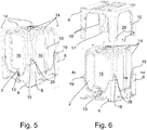
Fig. 5 is a view of a subassembly of the container according to the preferred embodiment of the invention; -
Fig. 6 is a view of a subassembly of the container according to the preferred embodiment of the invention; -
Fig. 7 shows the insertion of the fasteners for assembling the support structure of the container according to the preferred embodiment; -
Fig. 8 shows to structurally identical containers according to the preferred embodiment in a stacked arrangement; -
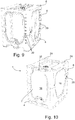
Fig. 9 shows a fill level indicating feature of the container according to the preferred embodiment; -
Fig. 10 shows an alternative embodiment of the invention; -
Fig. 11A shows a detailed view of a skid portion; -
Fig. 11B shows an alternative version of a skid portion; and -
Figs. 12 and 13 show an anti-rotation device according to a preferred embodiment of the invention. -
Fig. 1 shows a preferred embodiment of the container according to the invention in a perspective view. In particular, the shown container is a so-called intermediate bulk container (IBC) configured for the storage and transportation of large volumes of fluids, pastes, powders and the like. The container according to the depicted preferred embodiment has a fill volume of approximately 1000 liters. IBC type containers are usually mounted on top of a standard pallet or comprise a pallet-like (forklift compatible) lower section. Compared to the classical transport of liquid or granulated goods in steel barrels stacked on top of a pallet, IBCs provide the advantage of optimally utilizing the fill-volume provided by the pallet-format and reducing the net weight of the packaging. Furthermore, with typical 200 liter barrels, 5 working steps are necessary to withdraw the same amount of goods, when compared to one working step to withdraw 1000 liters from the depicted IBC. - Fundamentally, the
container 1 according to the preferred embodiment is structured such that it has aninternal tank 2 defining the fill volume of thecontainer 1 and having an inlet and an outlet opening and anexternal support structure internal tank 2 and supporting it in order to protect thetank 2 from outside damage and to provide the necessary structural integrity for stacking multiplesuch containers 1. Thesupport structure base structure 4 on which thetank 2 is supported as well as anupper support structure 6 that frames the top side of thetank 2, thus protecting thetank 2 from loads exerted from above, such as e.g. stacking loads. - The
base structure 4 of thesupport structure lower column portions 8, which are arranged in each of the four corners of thebase structure 4 and extend in an upward direction of thecontainer 1. Thebase structure 4 further comprises a peripheral,circumferential wall section 7, which connects thelower column portions 8 along the edges of thebase structure 4 and together with these forms a receivingarea 9 for the lower side of thetank 2 on the upper face of thebase structure 4. Thecircumferential wall portion 7 in the depicted embodiment is provided with an opening or cut-out 11 adapted to receive alower outlet valve 13 of thetank 2. This allows the valve to be accessed through the support structure and also provides a Poka-Yoke function by only allowing one orientation of the tank during assembly. - Although not explicitly depicted, the base wall of the
tank 2 as well as a top surface of thebase structure 4 that receives said base wall are slightly slanted towards thelower outlet valve 13 of thetank 2 to facilitate complete depletion of the tanks contents. - The
upper support structure 6 also has a rectangular cross-section when viewed from above and comprises fourupper column portions 10, which are arranged in the corners of theupper support structure 6 and extends downwards towards thebase structure 4. In an assembled state of thecontainer 1, thelower column portions 8 and theupper column portions 10 combine to form four corner columns orposts 12, thereby connecting thebase structure 8 and theupper support structure 10 and laterally supporting the edges of thetank 2. Thecolumns 12 also allow for stackability of thecontainer 1 by transferring stacking loads vertically, while bypassing thetank 2. - In order to improve handling during assembly of the
container 1 according to the preferred embodiment, the interface, where thelower column portion 8 and the upper column portion meet, is positioned at about one third of theentire container 1 height. This has been advantage that thelower column portions 8 can still effectively define a receiving area for thetank 2, while thetank 2 does not have to be lifted as high, in order to be inserted onto thebase structure 4 as is the case in other IBCs known from prior art, where the supporting cage extends substantially along the entire height of thecontainer 1. Further, such a height of the interface between thebase structure 4 and theupper support structure 6 has proven to be an ergonomically comfortable height for assembly personnel, when securing theupper support structure 6 with thebase structure 4 as will be elaborated later on. - As will be described in detail later on, the
corner columns 12 are further reinforced by reinforcingprofiles 14 which insert into both thelower column portions 8 and theupper column portions 10 thereby strengthening the connection between theseportions columns 12 and facilitating the absorption and transfer of stacking loads by thecolumns 12. -
Fig. 2 shows a perspective view of the underside of thecontainer 1 according to the preferred embodiment. This figure showcases the pallet shaped underside of thebase structure 4 which allows handling via forklifts and the like and which will be explained in greater detail later on. A further feature of the base structure is a hole-pattern 5, which provides additional strength and stiffness to the middle of the base structure 4 (the parts lifted by forklift forks and the like. - As best seen in
Fig. 3 , the pallet shapedbase structure 4 comprises a separate,attachable skid portion 22, which can be releasable fastened to the underside of the base structure by a number offasteners 26 inserted into correspondingbores 28. Thefasteners 26 can preferably be made (molded) of plastic (polymer) material and could be formed e.g. as screws, bolts, bayonet fasteners or the like. -
Fig. 3 can also be seen as a starting point of a bottom up assembly of thecontainer 1 according to the preferred embodiment of the invention, in which saidskid portion 22 is fixed to thepallet portion 20 of thebase structure 4 by insertingfasteners 26 into concentric bores provided both in theskid portion 22 and thepallet portion 20 of thebase structure 4. - After the
skid portion 22 is fastened to the underside of thebase structure 4, thebase structure 4 can be placed into an upright position and thetank 2 can be placed on top of thebase structure 4 into the receivingarea 9 formed by thecircumferential wall section 7 of thebase structure 4 and thelower column portions 8, as is shown inFig. 4 . -
Fig. 4 also highlights a structural feature of thetank 2 according to the preferred embodiment of the invention, which is the protrudingside wall portions 16 of the tank. The tank has a cuboid base shape. However the lateral faces of said cuboid base shape are designed such that they bulge outwardly through the windows formed by two neighboringcolumns 12, thebase structure 4 and theupper support structure 6. This allows the tank to "fill out" the remaining volume formed between said windows and the generally cuboid shape or silhouette of thesupport structure side wall portions 16 of thetank 2 are flattened to level with the cuboid outer silhouette of thesupport structure - In a next assembly step best seen in
Fig. 5 , reinforcingprofiles 14 are inserted into profile receiving recesses (or bores) 15 that are provided peripherally in thebase structure 4 for this purpose. One reinforcingprofile 14 is inserted into each of the lower column portions 8 (which each comprise a profile receiving recesses 15 for this purpose) and additional reinforcingprofiles 14 are arranged between two neighboringlower column portions 8, thereby laterally supporting thetank 2side wall portion 16 that is exposed between said two neighboring lower column portions 8 (respectively between the two neighboring columns 12). Such intermediate reinforcingprofiles 14 are provided on each of the sides of thecuboid support structure 6 with the exception of the side in which thelower outlet valve 13 to is arranged to improve the strength of thecontainer 1 against pressure loads placed on thetank 2. Since the tankside wall portions 16 protrude outwards,grooves 18 are provided therein to accommodate the intermediate reinforcing profiles 14. -
Fig. 6 depicts the next assembly step, in which theupper support structure 6 is placed on top of thecontainer 1 as assembled thus far. Naturally, the lower face of theupper support structure 6 is provided with profile receiving recesses 15, in order to accommodate the reinforcingprofiles 14 extending from the lower subassembly.
Additionally, the free ends of theupper column portions 10, which mate with the upper ends of thelower column portions 8, are provided withfastening recesses 17 for receivingfastening protrusions 19 arranged on said upper ends of thelower column portions 8. As the skilled person will appreciate, this arrangement may also be inversed as long as there is an area of overlap between theupper support structure 6 and thebase structure 4. In the depicted preferred embodiments eachupper column portion 10 and eachfastening protrusion 19 comprise a coaxial bore 28 (in the assembled state), which is configured to receive areleasable fastener 26. In this case, thefasteners 26 for connecting thebase structure 4 with theupper support structure 6 are identical to the fasteners connecting theskid portion 22 to thebase structure 4. This reduces the variety of parts necessary for manufacturing thecontainer 1 according to the preferred embodiment of the invention. Since in the depicted preferred embodiment thefasteners 26 are constructed as plastic molded parts, a single molding tool will suffice for their production. The insertion of thefasteners 26 into the receiving bores 28 of thelower column portions 8 and theupper column portions 10 is shown inFig. 7 . -
Fig. 8 shows two structurallyidentical containers 1, 1' according to the invention in a stacked position. The reinforcedcorner column 12 structure provides good stacking strength and an optimized load transfer through the corner columns and thus allows stacking ofcontainers 1, even in a filled state of thecontainers 1, 1'. -
Fig. 9 highlights a further feature of acontainer 1 according to a preferred embodiment of the invention. Thetank 2 shown here is made of an at least partially transparent polymer material. Because in such an embodiment the fill level is perceivable through the tank wall, afill scale 30 indicating the fill level may be provided on one of thecolumns 12 framing an exposedtank sidewall portion 16. Preferably thisfill scale 30 is provided on a frontside wall portion 16 of thetank 2 also carrying thelower outlet valve 13, such that the fill level can be monitored while emptying thecontainer 1. Saidfill scale 30 depicted inFig. 9 starts on the lower end of thelower column portion 8 and seamlessly continues on to the correspondingupper column portion 10 of thesame column 12. -
Figure 10 discloses an alternative embodiment of the present invention. The disclosedcontainer 1 has many structural similarities with theaforementioned container 1 of the preferred embodiment. In the following, for the sake of brevity, only differences between the embodiments will be discussed. One difference is the height in which thelower column portions 8 and theupper column portions 10 meet or the height of the interface, which in this case is about half the height of theentire container 1. Furthermore, the front window between the twofront columns 12 is extended upwards (cut-out at its upper rim) such that anextra sampling opening 32 may be provided and accessed in the top front edge of thetank 2. Such asampling opening 32 can be beneficial for certain use cases. Such an embodiment however has the drawback that the structural integrity of theupper support structure 6 is compromised by the extended front window. Lastly, this embodiment shows an alternative stacking geometry on the top face of theupper support structure 6, comprising stackingprotrusions 24 in each corner of such top face which are completely received by corresponding recesses (not shown) on the underside of thebase structure 4. -
Fig. 11 shows thecontainer 1 according to the preferred embodiment of the invention having multiple, exchangeable variations of theskid portion 22. In particular abase structure 4 is depicted, on which a first variation of askid portion 22 is mounted. This first variation is designed to form a so called "three skid pallet" that comprises three parallel elongated skids and is easy to handle with devices such as pallet wagons, fork lifts or pallet-jacks. A second variation of anexchangeable skid portion 34 is shown next to the assembledbase structure 4. The second variation forms a so called parametrical skid.Such skids 34 have onecircumferential skid portion 36 and onecentral skid portion 38 arranged centrally within thecircumferential skid portion 36 and provide the benefit of a more secured handling via forklift forks, when compared to e.g. three skid versions. Thebores 28 for inserting thefasteners 26 in thepallet portion 20 of thebase structure 6 and theskid portions bores 28 are possible as long as said placement is congruent between thepallet portion 20 of thebase structure 6 and theskid portions 22, 22'. -
Figures 12 and 13 depict another feature of thecontainer 1 of the preferred embodiment, which could provide subject-matter for a separate application. In particular an anti-rotation device for thelower outlet valve 13 is disclosed that comprises abase locking geometry 40 arranged in thevalve opening 11 of thebase structure 4 of thecontainer 1. Thisbase locking geometry 40 is configured to engage with a complementaryvalve locking geometry 42 arranged on the underside of thelower outlet valve 13 and extending towards thebase structure 4. In a state, in which thetank 2 is mounted on thebase structure 4, thebase locking geometry 40 and the complementaryvalve locking geometry 42 engage, such that a positive lock is formed between thevalve 13 and thebase structure 4, at least in the direction perpendicular to the outlet valve's 13 axial direction. This anchors the lower side of thelower outlet valve 13 against any rotational forces which can occur for example when a valve handle that is arranged opposite to thevalve locking geometry 42 on thevalve 13 is operated. In the depicted embodiment the two lockinggeometries -
- 1
- container (IBC)
- 2
- tank;
- 4
- base structure;
- 5
- hole-pattern;
- 6
- upper support structure;
- 7
- circumferential wall section;
- 8
- lower column portion;
- 9
- receiving area
- 10
- upper column portion;
- 11
- valve opening;
- 12
- column;
- 13
- lower outlet valve;
- 14
- reinforcing profile;
- 15
- profile receiving recesses;
- 16
- side wall portion;
- 17
- fastening recess;
- 18
- groove;
- 19
- fastening protrusion;
- 20
- pallet portion;
- 22
- skid portion;
- 24
- stacking geometry;
- 26
- fasteners;
- 28
- bores for fasteners;
- 30
- fill scale;
- 32
- sampling opening;
- 34
- parametrical skid portion;
- 36
- circumferential skid portion;
- 38
- central skid portion;
- 40
- base locking geometry; and
- 42
- valve locking geometry.
Claims (15)
- A container (1) for the transport and storage of, especially liquid or granulated, goods, more particular an intermediate bulk container, comprising an internal fillable tank (2) and an external support structure (4, 6) surrounding the tank (2), which has
a base structure (4) arranged below the tank (2), such that a base of the tank (2) is supported thereon; and
an upper support structure (6) arranged above the tank (2) for absorbing loads exerted on the tank (2) from above;
characterized in that,
the base structure (4) comprises a plurality of lower column portions (8), which project in an upward direction of the container (1), and
the upper support structure (6) comprises a plurality of corresponding upper column portions (10), which project in a downward direction of the container (1), such that each of the lower column portions (8) meets and combines with one of the upper column portions (10), in order to form a plurality of columns (12) for laterally supporting the tank (2). - The container (1) of claim 1, wherein the assembled support structure (4, 6) produces a cuboid outer shape of the container (1), the base structure (4) comprises the lower column portion (8) in each of its four corners and the upper support structure (6) also comprises the corresponding upper column portion (10) in each of its four corners, such that four corner columns (12) are formed.
- The container (1) according to one of claims 1 or 2, wherein the support structure (4, 6) further comprises a reinforcing profile (14) arranged internally in at least one of the columns (12), preferably in each of the columns (12), such that the reinforcing profile (14) extends internally along the length direction of the lower column portion (8) and the upper column portion (10) of the respective column (12).
- The container (1) according to one of claims 1 to 3, wherein the support structure (4, 6) further comprises a reinforcing profile (14) extending from the base structure (4) to the upper support structure (6) in a direction parallel to and arranged in between two columns (12), such that it laterally supports a side wall portion (16) of the tank (2) that is exposed between said two columns (12).
- The container (1) according to one of claims 3 or 4, wherein the at least one reinforcing profile (14) is an extrusion profile, in particular a hollow profile, made of a plastic material.
- The container (1) according to one of claims 1 to 5, wherein the tank (2) comprises at least one protruding portion (16), which outwardly protrudes into a window formed between the base structure (4), the upper support structure (6) and two columns (12), thereby increasing the internal volume of the tank (2).
- The container (1) according to claims 4 and 6, wherein the at least one protruding portion (16) comprises a groove (18) extending in a parallel direction to the columns (12) delimiting the window and wherein the at least one reinforcing profile (14) extending from the base structure (4) to the upper support structure (6) for laterally supporting the protruding side wall portion (16) is arranged within said groove (18) of the tank (2).
- The container (1) according to one of claims 1 to 7, wherein the base structure (4) comprises a pallet portion (20) on its lower face configured to cooperate with a forklift, pallet jack or the like.
- The container (1) according to claim 8, wherein the pallet portion (20) comprises a skid portion (22), which is detachably connected to its lower face.
- The container (1) according to one of claims 8 to 9, wherein the upper face of the upper support structure (6) comprises a plurality of stacking geometries (24) which are engageable with corresponding stacking geometries on the lower face of the pallet portion (20) and/or the skid portion (22) of a structurally identical container (1').
- The container (1) according to claim 10, wherein circumferential edges of the lower face of the skid portion (22) are recessed and configured to receive corresponding circumferential stacking projections (24) arranged on the upper face of the upper support structure (6).
- The container (1) according to one of claims 1 to 11, wherein at least one lower column portion (8) and one upper column portion (10) are releasably connected with one another by means of a fastener (26).
- The container (1) according to claim 12, wherein the skid portion (22) is connected to the base structure (4) with a plurality of fasteners (26), wherein said fasteners (26) are structurally identical to the fasteners connecting the lower column portion (8) or the upper column portion (10).
- The container (1) according to one of the aforementioned claims, wherein the interface, where the lower column portions (8) and the upper column portions (10) meet, is arranged between 1/5 and 4/5, preferably between 1/3 and 2/3, of the entire container (1) height.
- The container (1) according to one of the aforementioned claims, wherein the tank (2) comprises an outlet valve (13) arranged in proximity to its lower side and the base portion (4) comprises a base locking geometry (40) on its lower side configured to engage and interlock with a valve locking geometry (42) arranged on a lower side of the outlet valve (13) and extending towards the base portion (4), thus forming a direct positive lock between the outlet valve (13) and the base portion (4).
Priority Applications (3)
| Application Number | Priority Date | Filing Date | Title |
|---|---|---|---|
| EP18209534.9A EP3659941B1 (en) | 2018-11-30 | 2018-11-30 | Container comprising an internal fillable tank and an external support structure |
| ES18209534T ES2991680T3 (en) | 2018-11-30 | 2018-11-30 | Container comprising a refillable inner reservoir and an outer support structure |
| US16/698,004 US11407583B2 (en) | 2018-11-30 | 2019-11-27 | Intermediate bulk container |
Applications Claiming Priority (1)
| Application Number | Priority Date | Filing Date | Title |
|---|---|---|---|
| EP18209534.9A EP3659941B1 (en) | 2018-11-30 | 2018-11-30 | Container comprising an internal fillable tank and an external support structure |
Publications (2)
| Publication Number | Publication Date |
|---|---|
| EP3659941A1 true EP3659941A1 (en) | 2020-06-03 |
| EP3659941B1 EP3659941B1 (en) | 2024-08-21 |
Family
ID=64564685
Family Applications (1)
| Application Number | Title | Priority Date | Filing Date |
|---|---|---|---|
| EP18209534.9A Active EP3659941B1 (en) | 2018-11-30 | 2018-11-30 | Container comprising an internal fillable tank and an external support structure |
Country Status (3)
| Country | Link |
|---|---|
| US (1) | US11407583B2 (en) |
| EP (1) | EP3659941B1 (en) |
| ES (1) | ES2991680T3 (en) |
Families Citing this family (4)
| Publication number | Priority date | Publication date | Assignee | Title |
|---|---|---|---|---|
| US20220314487A1 (en) * | 2019-05-23 | 2022-10-06 | General Electric Company | Build receptacles for additive manufacturing apparatuses and methods for using the same |
| DE102020105525A1 (en) * | 2020-03-02 | 2021-09-02 | Protechna S.A. | Inner containers made of plastic and transport and storage containers for liquids with an inner container made of plastic |
| IT202400003595A1 (en) | 2024-02-21 | 2025-08-21 | Greif Int Holding B V | PALLET TO SUPPORT A LIQUID CONTAINER AND IBC PALLETIZED CONTAINER INCLUDING THE PALLET. |
| CN118458178B (en) * | 2024-07-09 | 2024-12-17 | 呼伦贝尔安泰热电有限责任公司扎兰屯热电厂 | Urea solution removes and accomodates jar that thermal power plant used |
Citations (4)
| Publication number | Priority date | Publication date | Assignee | Title |
|---|---|---|---|---|
| JPH07232791A (en) * | 1994-02-15 | 1995-09-05 | Toho Sheet & Frame Co Ltd | Container structure and container container used for it |
| EP0805115A1 (en) * | 1996-05-02 | 1997-11-05 | ALLIBERT EQUIPEMENT (Société Anonyme), société dite: | Packaging unit for dangerous products |
| US20010051079A1 (en) * | 1999-12-20 | 2001-12-13 | Ricoh Company Limited | Method for handling goods |
| WO2015042651A1 (en) * | 2013-09-30 | 2015-04-02 | Flextank International Limited | Closure assembly |
Family Cites Families (10)
| Publication number | Priority date | Publication date | Assignee | Title |
|---|---|---|---|---|
| US3940018A (en) * | 1972-09-25 | 1976-02-24 | Scholle Corporation | Combination liquid container and dispenser |
| FI76764C (en) * | 1986-10-02 | 1988-12-12 | Fluid Bag Ab Oy | FLEXIBEL BEHAOLLARE FOER FLUIDER. |
| US4703702A (en) * | 1986-10-16 | 1987-11-03 | Ready Metal Manufacturing Company | Multi-level pallet assembly |
| US4817824A (en) * | 1986-12-08 | 1989-04-04 | Custom Packaging Systems, Inc. | Collapsible bulk container |
| GB9212032D0 (en) * | 1992-06-05 | 1992-07-15 | Farrell Peter J | Collapsible container apparatus for fluid material |
| US5667002A (en) * | 1996-10-17 | 1997-09-16 | Air Cargo Equipment Corporation | Single-point tensioning door system for containers |
| US5897012A (en) * | 1997-04-04 | 1999-04-27 | Sortwell & Co. | Collapsible intermediate bulk container |
| US6514009B2 (en) * | 1998-12-01 | 2003-02-04 | Robert William Northcott | Subterranean storage vessel system |
| US6247594B1 (en) * | 2000-08-31 | 2001-06-19 | Snyder Industries, Inc. | Fluid tank assembly |
| DE20100219U1 (en) * | 2001-01-08 | 2001-07-05 | Bothor, Kerim Patrick, 22397 Hamburg | Device for receiving, transporting, controlled emptying and storage of flowable bulk goods in large-volume containers |
-
2018
- 2018-11-30 EP EP18209534.9A patent/EP3659941B1/en active Active
- 2018-11-30 ES ES18209534T patent/ES2991680T3/en active Active
-
2019
- 2019-11-27 US US16/698,004 patent/US11407583B2/en active Active
Patent Citations (4)
| Publication number | Priority date | Publication date | Assignee | Title |
|---|---|---|---|---|
| JPH07232791A (en) * | 1994-02-15 | 1995-09-05 | Toho Sheet & Frame Co Ltd | Container structure and container container used for it |
| EP0805115A1 (en) * | 1996-05-02 | 1997-11-05 | ALLIBERT EQUIPEMENT (Société Anonyme), société dite: | Packaging unit for dangerous products |
| US20010051079A1 (en) * | 1999-12-20 | 2001-12-13 | Ricoh Company Limited | Method for handling goods |
| WO2015042651A1 (en) * | 2013-09-30 | 2015-04-02 | Flextank International Limited | Closure assembly |
Also Published As
| Publication number | Publication date |
|---|---|
| US11407583B2 (en) | 2022-08-09 |
| US20200172328A1 (en) | 2020-06-04 |
| EP3659941B1 (en) | 2024-08-21 |
| ES2991680T3 (en) | 2024-12-04 |
Similar Documents
| Publication | Publication Date | Title |
|---|---|---|
| US11407583B2 (en) | Intermediate bulk container | |
| CA2512817C (en) | Nestable pallet | |
| US4809851A (en) | Collapsible container | |
| EP0629558B2 (en) | Stackable container | |
| US6805254B2 (en) | Collapsible container | |
| US20090050030A1 (en) | Nestable pallet | |
| KR20120125175A (en) | Skid pallet in particular for transport and storage containers for liquids | |
| ITMI20010343A1 (en) | SHOVEL CONTAINER FOR LIQUIDS | |
| JP6861724B2 (en) | Pallet container | |
| US20060032854A1 (en) | Plastic tank for liquids | |
| MX2013000709A (en) | Metallic pallet with frame and panel support surface. | |
| US20160362223A1 (en) | Stackable pallet container fitted with a top reinforcement frame | |
| US20240034512A1 (en) | Pallet base, intermediate bulk container, method of assembly of an intermediate bulk container, runner and deck structure | |
| AU2020205167A1 (en) | Assortment of pallet modules, and pallet assembly built of the same | |
| EP2999638B1 (en) | Shipping container | |
| CA2804875C (en) | Stackable pallet container | |
| KR101115606B1 (en) | Structure for reinforcing strength in pallet | |
| KR100820002B1 (en) | Prefabricated container | |
| MXPA03010495A (en) | Pallet-like base, particularly for transport and storage containers for liquids. | |
| JP2772469B2 (en) | Pallet with discharge function for containers | |
| EP1744966B1 (en) | Palette | |
| EP1737737B1 (en) | Knock-down crate with walls stored in base and method employing such a crate | |
| JP4991264B2 (en) | palette | |
| CN222117382U (en) | High-strength fence pallet | |
| JP2025081839A (en) | Pallet |
Legal Events
| Date | Code | Title | Description |
|---|---|---|---|
| PUAI | Public reference made under article 153(3) epc to a published international application that has entered the european phase |
Free format text: ORIGINAL CODE: 0009012 |
|
| STAA | Information on the status of an ep patent application or granted ep patent |
Free format text: STATUS: REQUEST FOR EXAMINATION WAS MADE |
|
| 17P | Request for examination filed |
Effective date: 20200402 |
|
| AK | Designated contracting states |
Kind code of ref document: A1 Designated state(s): AL AT BE BG CH CY CZ DE DK EE ES FI FR GB GR HR HU IE IS IT LI LT LU LV MC MK MT NL NO PL PT RO RS SE SI SK SM TR |
|
| AX | Request for extension of the european patent |
Extension state: BA ME |
|
| STAA | Information on the status of an ep patent application or granted ep patent |
Free format text: STATUS: EXAMINATION IS IN PROGRESS |
|
| 17Q | First examination report despatched |
Effective date: 20201020 |
|
| GRAP | Despatch of communication of intention to grant a patent |
Free format text: ORIGINAL CODE: EPIDOSNIGR1 |
|
| STAA | Information on the status of an ep patent application or granted ep patent |
Free format text: STATUS: GRANT OF PATENT IS INTENDED |
|
| RIC1 | Information provided on ipc code assigned before grant |
Ipc: B65D 25/56 20060101ALN20240229BHEP Ipc: B65D 88/12 20060101ALI20240229BHEP Ipc: B65D 85/30 20060101ALI20240229BHEP Ipc: B65D 21/02 20060101ALI20240229BHEP Ipc: B65D 1/18 20060101ALI20240229BHEP Ipc: B65D 88/02 20060101ALI20240229BHEP Ipc: B65D 19/18 20060101ALI20240229BHEP Ipc: B65D 77/04 20060101AFI20240229BHEP |
|
| INTG | Intention to grant announced |
Effective date: 20240319 |
|
| P01 | Opt-out of the competence of the unified patent court (upc) registered |
Effective date: 20240408 |
|
| GRAS | Grant fee paid |
Free format text: ORIGINAL CODE: EPIDOSNIGR3 |
|
| GRAA | (expected) grant |
Free format text: ORIGINAL CODE: 0009210 |
|
| STAA | Information on the status of an ep patent application or granted ep patent |
Free format text: STATUS: THE PATENT HAS BEEN GRANTED |
|
| AK | Designated contracting states |
Kind code of ref document: B1 Designated state(s): AL AT BE BG CH CY CZ DE DK EE ES FI FR GB GR HR HU IE IS IT LI LT LU LV MC MK MT NL NO PL PT RO RS SE SI SK SM TR |
|
| RAP3 | Party data changed (applicant data changed or rights of an application transferred) |
Owner name: SCHOELLER ALLIBERT GMBH |
|
| REG | Reference to a national code |
Ref country code: GB Ref legal event code: FG4D |
|
| REG | Reference to a national code |
Ref country code: CH Ref legal event code: EP |
|
| REG | Reference to a national code |
Ref country code: DE Ref legal event code: R096 Ref document number: 602018073301 Country of ref document: DE |
|
| REG | Reference to a national code |
Ref country code: IE Ref legal event code: FG4D |
|
| REG | Reference to a national code |
Ref country code: ES Ref legal event code: FG2A Ref document number: 2991680 Country of ref document: ES Kind code of ref document: T3 Effective date: 20241204 |
|
| REG | Reference to a national code |
Ref country code: LT Ref legal event code: MG9D |
|
| REG | Reference to a national code |
Ref country code: NL Ref legal event code: MP Effective date: 20240821 |
|
| PG25 | Lapsed in a contracting state [announced via postgrant information from national office to epo] |
Ref country code: NO Free format text: LAPSE BECAUSE OF FAILURE TO SUBMIT A TRANSLATION OF THE DESCRIPTION OR TO PAY THE FEE WITHIN THE PRESCRIBED TIME-LIMIT Effective date: 20241121 |
|
| REG | Reference to a national code |
Ref country code: AT Ref legal event code: MK05 Ref document number: 1715316 Country of ref document: AT Kind code of ref document: T Effective date: 20240821 |
|
| PG25 | Lapsed in a contracting state [announced via postgrant information from national office to epo] |
Ref country code: PT Free format text: LAPSE BECAUSE OF FAILURE TO SUBMIT A TRANSLATION OF THE DESCRIPTION OR TO PAY THE FEE WITHIN THE PRESCRIBED TIME-LIMIT Effective date: 20241223 Ref country code: FI Free format text: LAPSE BECAUSE OF FAILURE TO SUBMIT A TRANSLATION OF THE DESCRIPTION OR TO PAY THE FEE WITHIN THE PRESCRIBED TIME-LIMIT Effective date: 20240821 Ref country code: NL Free format text: LAPSE BECAUSE OF FAILURE TO SUBMIT A TRANSLATION OF THE DESCRIPTION OR TO PAY THE FEE WITHIN THE PRESCRIBED TIME-LIMIT Effective date: 20240821 Ref country code: PL Free format text: LAPSE BECAUSE OF FAILURE TO SUBMIT A TRANSLATION OF THE DESCRIPTION OR TO PAY THE FEE WITHIN THE PRESCRIBED TIME-LIMIT Effective date: 20240821 Ref country code: GR Free format text: LAPSE BECAUSE OF FAILURE TO SUBMIT A TRANSLATION OF THE DESCRIPTION OR TO PAY THE FEE WITHIN THE PRESCRIBED TIME-LIMIT Effective date: 20241122 |
|
| PG25 | Lapsed in a contracting state [announced via postgrant information from national office to epo] |
Ref country code: BG Free format text: LAPSE BECAUSE OF FAILURE TO SUBMIT A TRANSLATION OF THE DESCRIPTION OR TO PAY THE FEE WITHIN THE PRESCRIBED TIME-LIMIT Effective date: 20240821 |
|
| PG25 | Lapsed in a contracting state [announced via postgrant information from national office to epo] |
Ref country code: LV Free format text: LAPSE BECAUSE OF FAILURE TO SUBMIT A TRANSLATION OF THE DESCRIPTION OR TO PAY THE FEE WITHIN THE PRESCRIBED TIME-LIMIT Effective date: 20240821 |
|
| PG25 | Lapsed in a contracting state [announced via postgrant information from national office to epo] |
Ref country code: AT Free format text: LAPSE BECAUSE OF FAILURE TO SUBMIT A TRANSLATION OF THE DESCRIPTION OR TO PAY THE FEE WITHIN THE PRESCRIBED TIME-LIMIT Effective date: 20240821 Ref country code: IS Free format text: LAPSE BECAUSE OF FAILURE TO SUBMIT A TRANSLATION OF THE DESCRIPTION OR TO PAY THE FEE WITHIN THE PRESCRIBED TIME-LIMIT Effective date: 20241221 |
|
| PG25 | Lapsed in a contracting state [announced via postgrant information from national office to epo] |
Ref country code: HR Free format text: LAPSE BECAUSE OF FAILURE TO SUBMIT A TRANSLATION OF THE DESCRIPTION OR TO PAY THE FEE WITHIN THE PRESCRIBED TIME-LIMIT Effective date: 20240821 |
|
| PG25 | Lapsed in a contracting state [announced via postgrant information from national office to epo] |
Ref country code: RS Free format text: LAPSE BECAUSE OF FAILURE TO SUBMIT A TRANSLATION OF THE DESCRIPTION OR TO PAY THE FEE WITHIN THE PRESCRIBED TIME-LIMIT Effective date: 20241121 |
|
| PG25 | Lapsed in a contracting state [announced via postgrant information from national office to epo] |
Ref country code: RS Free format text: LAPSE BECAUSE OF FAILURE TO SUBMIT A TRANSLATION OF THE DESCRIPTION OR TO PAY THE FEE WITHIN THE PRESCRIBED TIME-LIMIT Effective date: 20241121 Ref country code: PT Free format text: LAPSE BECAUSE OF FAILURE TO SUBMIT A TRANSLATION OF THE DESCRIPTION OR TO PAY THE FEE WITHIN THE PRESCRIBED TIME-LIMIT Effective date: 20241223 Ref country code: PL Free format text: LAPSE BECAUSE OF FAILURE TO SUBMIT A TRANSLATION OF THE DESCRIPTION OR TO PAY THE FEE WITHIN THE PRESCRIBED TIME-LIMIT Effective date: 20240821 Ref country code: NO Free format text: LAPSE BECAUSE OF FAILURE TO SUBMIT A TRANSLATION OF THE DESCRIPTION OR TO PAY THE FEE WITHIN THE PRESCRIBED TIME-LIMIT Effective date: 20241121 Ref country code: NL Free format text: LAPSE BECAUSE OF FAILURE TO SUBMIT A TRANSLATION OF THE DESCRIPTION OR TO PAY THE FEE WITHIN THE PRESCRIBED TIME-LIMIT Effective date: 20240821 Ref country code: LV Free format text: LAPSE BECAUSE OF FAILURE TO SUBMIT A TRANSLATION OF THE DESCRIPTION OR TO PAY THE FEE WITHIN THE PRESCRIBED TIME-LIMIT Effective date: 20240821 Ref country code: IS Free format text: LAPSE BECAUSE OF FAILURE TO SUBMIT A TRANSLATION OF THE DESCRIPTION OR TO PAY THE FEE WITHIN THE PRESCRIBED TIME-LIMIT Effective date: 20241221 Ref country code: HR Free format text: LAPSE BECAUSE OF FAILURE TO SUBMIT A TRANSLATION OF THE DESCRIPTION OR TO PAY THE FEE WITHIN THE PRESCRIBED TIME-LIMIT Effective date: 20240821 Ref country code: GR Free format text: LAPSE BECAUSE OF FAILURE TO SUBMIT A TRANSLATION OF THE DESCRIPTION OR TO PAY THE FEE WITHIN THE PRESCRIBED TIME-LIMIT Effective date: 20241122 Ref country code: FI Free format text: LAPSE BECAUSE OF FAILURE TO SUBMIT A TRANSLATION OF THE DESCRIPTION OR TO PAY THE FEE WITHIN THE PRESCRIBED TIME-LIMIT Effective date: 20240821 Ref country code: BG Free format text: LAPSE BECAUSE OF FAILURE TO SUBMIT A TRANSLATION OF THE DESCRIPTION OR TO PAY THE FEE WITHIN THE PRESCRIBED TIME-LIMIT Effective date: 20240821 Ref country code: AT Free format text: LAPSE BECAUSE OF FAILURE TO SUBMIT A TRANSLATION OF THE DESCRIPTION OR TO PAY THE FEE WITHIN THE PRESCRIBED TIME-LIMIT Effective date: 20240821 |
|
| PG25 | Lapsed in a contracting state [announced via postgrant information from national office to epo] |
Ref country code: RO Free format text: LAPSE BECAUSE OF FAILURE TO SUBMIT A TRANSLATION OF THE DESCRIPTION OR TO PAY THE FEE WITHIN THE PRESCRIBED TIME-LIMIT Effective date: 20240821 Ref country code: DK Free format text: LAPSE BECAUSE OF FAILURE TO SUBMIT A TRANSLATION OF THE DESCRIPTION OR TO PAY THE FEE WITHIN THE PRESCRIBED TIME-LIMIT Effective date: 20240821 Ref country code: SM Free format text: LAPSE BECAUSE OF FAILURE TO SUBMIT A TRANSLATION OF THE DESCRIPTION OR TO PAY THE FEE WITHIN THE PRESCRIBED TIME-LIMIT Effective date: 20240821 |
|
| PG25 | Lapsed in a contracting state [announced via postgrant information from national office to epo] |
Ref country code: EE Free format text: LAPSE BECAUSE OF FAILURE TO SUBMIT A TRANSLATION OF THE DESCRIPTION OR TO PAY THE FEE WITHIN THE PRESCRIBED TIME-LIMIT Effective date: 20240821 |
|
| PG25 | Lapsed in a contracting state [announced via postgrant information from national office to epo] |
Ref country code: CZ Free format text: LAPSE BECAUSE OF FAILURE TO SUBMIT A TRANSLATION OF THE DESCRIPTION OR TO PAY THE FEE WITHIN THE PRESCRIBED TIME-LIMIT Effective date: 20240821 |
|
| PG25 | Lapsed in a contracting state [announced via postgrant information from national office to epo] |
Ref country code: SK Free format text: LAPSE BECAUSE OF FAILURE TO SUBMIT A TRANSLATION OF THE DESCRIPTION OR TO PAY THE FEE WITHIN THE PRESCRIBED TIME-LIMIT Effective date: 20240821 |
|
| REG | Reference to a national code |
Ref country code: DE Ref legal event code: R097 Ref document number: 602018073301 Country of ref document: DE |
|
| REG | Reference to a national code |
Ref country code: DE Ref legal event code: R119 Ref document number: 602018073301 Country of ref document: DE |
|
| PLBE | No opposition filed within time limit |
Free format text: ORIGINAL CODE: 0009261 |
|
| STAA | Information on the status of an ep patent application or granted ep patent |
Free format text: STATUS: NO OPPOSITION FILED WITHIN TIME LIMIT |
|
| REG | Reference to a national code |
Ref country code: CH Ref legal event code: PL |
|
| PG25 | Lapsed in a contracting state [announced via postgrant information from national office to epo] |
Ref country code: MC Free format text: LAPSE BECAUSE OF FAILURE TO SUBMIT A TRANSLATION OF THE DESCRIPTION OR TO PAY THE FEE WITHIN THE PRESCRIBED TIME-LIMIT Effective date: 20240821 |
|
| PG25 | Lapsed in a contracting state [announced via postgrant information from national office to epo] |
Ref country code: LU Free format text: LAPSE BECAUSE OF NON-PAYMENT OF DUE FEES Effective date: 20241130 |
|
| REG | Reference to a national code |
Ref country code: CH Ref legal event code: PL |
|
| GBPC | Gb: european patent ceased through non-payment of renewal fee |
Effective date: 20241130 |
|
| PG25 | Lapsed in a contracting state [announced via postgrant information from national office to epo] |
Ref country code: CH Free format text: LAPSE BECAUSE OF NON-PAYMENT OF DUE FEES Effective date: 20241130 |
|
| 26N | No opposition filed |
Effective date: 20250522 |
|
| REG | Reference to a national code |
Ref country code: BE Ref legal event code: MM Effective date: 20241130 |
|
| PG25 | Lapsed in a contracting state [announced via postgrant information from national office to epo] |
Ref country code: SE Free format text: LAPSE BECAUSE OF FAILURE TO SUBMIT A TRANSLATION OF THE DESCRIPTION OR TO PAY THE FEE WITHIN THE PRESCRIBED TIME-LIMIT Effective date: 20240821 |
|
| PG25 | Lapsed in a contracting state [announced via postgrant information from national office to epo] |
Ref country code: DE Free format text: LAPSE BECAUSE OF NON-PAYMENT OF DUE FEES Effective date: 20250603 |
|
| PG25 | Lapsed in a contracting state [announced via postgrant information from national office to epo] |
Ref country code: GB Free format text: LAPSE BECAUSE OF NON-PAYMENT OF DUE FEES Effective date: 20241130 Ref country code: BE Free format text: LAPSE BECAUSE OF NON-PAYMENT OF DUE FEES Effective date: 20241130 |
|
| PG25 | Lapsed in a contracting state [announced via postgrant information from national office to epo] |
Ref country code: IE Free format text: LAPSE BECAUSE OF NON-PAYMENT OF DUE FEES Effective date: 20241130 |
|
| PGFP | Annual fee paid to national office [announced via postgrant information from national office to epo] |
Ref country code: IT Payment date: 20251128 Year of fee payment: 8 |
|
| PGFP | Annual fee paid to national office [announced via postgrant information from national office to epo] |
Ref country code: FR Payment date: 20251120 Year of fee payment: 8 |
|
| PGFP | Annual fee paid to national office [announced via postgrant information from national office to epo] |
Ref country code: ES Payment date: 20251216 Year of fee payment: 8 |
|
| PG25 | Lapsed in a contracting state [announced via postgrant information from national office to epo] |
Ref country code: CY Free format text: LAPSE BECAUSE OF FAILURE TO SUBMIT A TRANSLATION OF THE DESCRIPTION OR TO PAY THE FEE WITHIN THE PRESCRIBED TIME-LIMIT; INVALID AB INITIO Effective date: 20181130 |
|
| PG25 | Lapsed in a contracting state [announced via postgrant information from national office to epo] |
Ref country code: TR Free format text: LAPSE BECAUSE OF FAILURE TO SUBMIT A TRANSLATION OF THE DESCRIPTION OR TO PAY THE FEE WITHIN THE PRESCRIBED TIME-LIMIT Effective date: 20240821 |
|
| PG25 | Lapsed in a contracting state [announced via postgrant information from national office to epo] |
Ref country code: HU Free format text: LAPSE BECAUSE OF FAILURE TO SUBMIT A TRANSLATION OF THE DESCRIPTION OR TO PAY THE FEE WITHIN THE PRESCRIBED TIME-LIMIT; INVALID AB INITIO Effective date: 20181130 |
|
| PG25 | Lapsed in a contracting state [announced via postgrant information from national office to epo] |
Ref country code: SI Free format text: LAPSE BECAUSE OF FAILURE TO SUBMIT A TRANSLATION OF THE DESCRIPTION OR TO PAY THE FEE WITHIN THE PRESCRIBED TIME-LIMIT Effective date: 20240821 |
|
| PG25 | Lapsed in a contracting state [announced via postgrant information from national office to epo] |
Ref country code: LT Free format text: LAPSE BECAUSE OF FAILURE TO SUBMIT A TRANSLATION OF THE DESCRIPTION OR TO PAY THE FEE WITHIN THE PRESCRIBED TIME-LIMIT Effective date: 20240821 |