EP3659912A1 - Aerial vehicles with uncoupled degrees of freedom - Google Patents
Aerial vehicles with uncoupled degrees of freedom Download PDFInfo
- Publication number
- EP3659912A1 EP3659912A1 EP18382880.5A EP18382880A EP3659912A1 EP 3659912 A1 EP3659912 A1 EP 3659912A1 EP 18382880 A EP18382880 A EP 18382880A EP 3659912 A1 EP3659912 A1 EP 3659912A1
- Authority
- EP
- European Patent Office
- Prior art keywords
- aerial vehicle
- multicopter
- main frame
- units
- joints
- Prior art date
- Legal status (The legal status is an assumption and is not a legal conclusion. Google has not performed a legal analysis and makes no representation as to the accuracy of the status listed.)
- Granted
Links
Images



Classifications
-
- B—PERFORMING OPERATIONS; TRANSPORTING
- B64—AIRCRAFT; AVIATION; COSMONAUTICS
- B64C—AEROPLANES; HELICOPTERS
- B64C27/00—Rotorcraft; Rotors peculiar thereto
- B64C27/04—Helicopters
- B64C27/08—Helicopters with two or more rotors
-
- B—PERFORMING OPERATIONS; TRANSPORTING
- B64—AIRCRAFT; AVIATION; COSMONAUTICS
- B64C—AEROPLANES; HELICOPTERS
- B64C27/00—Rotorcraft; Rotors peculiar thereto
- B64C27/20—Rotorcraft characterised by having shrouded rotors, e.g. flying platforms
-
- B—PERFORMING OPERATIONS; TRANSPORTING
- B64—AIRCRAFT; AVIATION; COSMONAUTICS
- B64C—AEROPLANES; HELICOPTERS
- B64C27/00—Rotorcraft; Rotors peculiar thereto
- B64C27/52—Tilting of rotor bodily relative to fuselage
-
- B—PERFORMING OPERATIONS; TRANSPORTING
- B64—AIRCRAFT; AVIATION; COSMONAUTICS
- B64U—UNMANNED AERIAL VEHICLES [UAV]; EQUIPMENT THEREFOR
- B64U10/00—Type of UAV
- B64U10/10—Rotorcrafts
- B64U10/13—Flying platforms
- B64U10/14—Flying platforms with four distinct rotor axes, e.g. quadcopters
-
- B—PERFORMING OPERATIONS; TRANSPORTING
- B64—AIRCRAFT; AVIATION; COSMONAUTICS
- B64U—UNMANNED AERIAL VEHICLES [UAV]; EQUIPMENT THEREFOR
- B64U30/00—Means for producing lift; Empennages; Arrangements thereof
- B64U30/20—Rotors; Rotor supports
- B64U30/29—Constructional aspects of rotors or rotor supports; Arrangements thereof
- B64U30/296—Rotors with variable spatial positions relative to the UAV body
- B64U30/297—Tilting rotors
-
- G—PHYSICS
- G05—CONTROLLING; REGULATING
- G05D—SYSTEMS FOR CONTROLLING OR REGULATING NON-ELECTRIC VARIABLES
- G05D1/00—Control of position, course, altitude or attitude of land, water, air or space vehicles, e.g. using automatic pilots
- G05D1/40—Control within particular dimensions
- G05D1/49—Control of attitude, i.e. control of roll, pitch or yaw
-
- G—PHYSICS
- G05—CONTROLLING; REGULATING
- G05D—SYSTEMS FOR CONTROLLING OR REGULATING NON-ELECTRIC VARIABLES
- G05D1/00—Control of position, course, altitude or attitude of land, water, air or space vehicles, e.g. using automatic pilots
- G05D1/60—Intended control result
- G05D1/69—Coordinated control of the position or course of two or more vehicles
- G05D1/695—Coordinated control of the position or course of two or more vehicles for maintaining a fixed relative position of the vehicles, e.g. for convoy travelling or formation flight
- G05D1/696—Coordinated control of the position or course of two or more vehicles for maintaining a fixed relative position of the vehicles, e.g. for convoy travelling or formation flight involving a plurality of vehicles coupled together
-
- B—PERFORMING OPERATIONS; TRANSPORTING
- B64—AIRCRAFT; AVIATION; COSMONAUTICS
- B64U—UNMANNED AERIAL VEHICLES [UAV]; EQUIPMENT THEREFOR
- B64U2101/00—UAVs specially adapted for particular uses or applications
- B64U2101/60—UAVs specially adapted for particular uses or applications for transporting passengers; for transporting goods other than weapons
- B64U2101/61—UAVs specially adapted for particular uses or applications for transporting passengers; for transporting goods other than weapons for transporting passengers
-
- B—PERFORMING OPERATIONS; TRANSPORTING
- B64—AIRCRAFT; AVIATION; COSMONAUTICS
- B64U—UNMANNED AERIAL VEHICLES [UAV]; EQUIPMENT THEREFOR
- B64U2201/00—UAVs characterised by their flight controls
- B64U2201/10—UAVs characterised by their flight controls autonomous, i.e. by navigating independently from ground or air stations, e.g. by using inertial navigation systems [INS]
-
- B—PERFORMING OPERATIONS; TRANSPORTING
- B64—AIRCRAFT; AVIATION; COSMONAUTICS
- B64U—UNMANNED AERIAL VEHICLES [UAV]; EQUIPMENT THEREFOR
- B64U2201/00—UAVs characterised by their flight controls
- B64U2201/20—Remote controls
-
- G—PHYSICS
- G05—CONTROLLING; REGULATING
- G05D—SYSTEMS FOR CONTROLLING OR REGULATING NON-ELECTRIC VARIABLES
- G05D2105/00—Specific applications of the controlled vehicles
- G05D2105/20—Specific applications of the controlled vehicles for transportation
- G05D2105/22—Specific applications of the controlled vehicles for transportation of humans
- G05D2105/24—Specific applications of the controlled vehicles for transportation of humans personal mobility devices
-
- G—PHYSICS
- G05—CONTROLLING; REGULATING
- G05D—SYSTEMS FOR CONTROLLING OR REGULATING NON-ELECTRIC VARIABLES
- G05D2109/00—Types of controlled vehicles
- G05D2109/20—Aircraft, e.g. drones
- G05D2109/25—Rotorcrafts
- G05D2109/254—Flying platforms, e.g. multicopters
Definitions
- the increase in motion accuracy allows aerial vehicles with independent DOF to perform tasks, e.g., precision handling of sensitive loads, precision landings, etc., that existing multicopters with interdependent DOF cannot. It also allows the aircraft to be provided with extended manoeuvrability that may be critical in missions where flight conditions are changing (gusty wind, variable or mobile payload) or where this extended manoeuvrability is necessary for certain manoeuvres or complex and very demanding flight dynamics.
- the basic modes of moving forward, backward, left and right can be generated by simply developing the same forces in each one of the multicopter units, as each multicopter unit would be positioned at the same tilt angle with the same thrust force being applied.
- the aerial vehicle would move depending on the thrust generated and the tilt angle at which the multicopter units are being operated.
- the main frame may have a plurality of arms extending radially therefrom and each operable multicopter unit may be attached to a corresponding arm of the plurality of arms.
- the joints may be located in proximity to the free ends of the arms such that the multicopter units are coupled to the frame via the respective free ends of the arms.
- a method for manoeuvring an aerial vehicle as previously disclosed may comprise determining, by the referencing processing unit, a displacement of the aerial vehicle relative to a horizontal plane. Then, the controller may determine a set point or thrust vector, i.e., a thrust magnitude and a tilt angle (yaw, roll and pitch angles), for the aerial vehicle based on the determined displacement. The controller may adjust the thrust of each multicopter unit based on the determined thrust.
- a thrust vector i.e., a thrust magnitude and a tilt angle (yaw, roll and pitch angles
- the controller may further adjust the tilt angle, i.e., yaw, roll and pitch, of the plurality of multicopter units by performing a rotational movement of each multicopter units relative to the main frame via the respective joints, the relative rotational movement being based on the tilt angle determined for the aerial vehicle.
- the sum of the thrust vectors in the plurality of multicopter units will be equal to the calculated thrust vector of the aerial vehicle to perform a certain manoeuvre. This example provides a centralised management of the aerial vehicle.
- the aerial vehicle may have a primary controller attached to the main frame and a secondary controller attached to each multicopter unit.
- the plurality of secondary controllers may be to operate the respective multicopter units and the primary controller may be to manage the plurality of secondary controllers.
- the primary controller may determine the thrust and the tilt angle for the aerial vehicle based on the determined displacement.
- Each one of the secondary controllers upon reception of the thrust and tilt angle for the aerial vehicle from the primary controller, may determine and adjust the particular thrust of the multicopter unit on which the secondary controller is mounted based on the thrust determined previously for the aerial vehicle.
- Each secondary controller may further determine and adjust the tilt angle of the respective multicopter unit by performing a rotational movement of the multicopter unit relative to the main frame via the joints, the relative rotational movement being based on the tilt angle previously determined for the aerial vehicle.
- the sum of the thrust vectors of the plurality of multicopter units will be equal to the calculated thrust vector of the aerial vehicle to perform a certain manoeuvre. This example provides a decentralised management of the aerial vehicle.
- the at least one controller may determine a different setpoint (thrust and tilt angles, roll, pitch and yaw) for each one of the quadcopters 2 providing the aerial vehicle 1 with additional operation modes other than basic operation modes (these basic operation modes are those movements performed by an aerial vehicle having a common setpoint for all its multicopter units).
- additional operation modes are stability modes in which multicopters are with inverse rotor angle such that forces generated by the multicopters counteract each other increasing the stability of the aircraft, precision modes due to the increased manoeuvrability of the aerial vehicle with uncoupled DOF or efficient cruising modes in which the multicopter units can be positioned in its cruising position but at the same time maintaining the capsule in a position that minimizes aerodynamic drag.
- the main frame 3 and the airframe body 8 may be releasably attached, or may be integrally formed with one another.
- the airframe body 8 may also comprise a structure to carry other elements such as batteries, different kind of payloads, etc.
- Fig. 1 shows an aerial vehicle 1 formed by four quadcopters 2, it will be apparent that any other suitable aerial vehicle architecture, including any number of multicopter units arranged to the main frame and any number of propulsion units arranged to each multicopter unit may be utilised to provide the multicopter functionality to the aerial vehicle 1.
- Fig. 1 shows the four quadcopters 2 linked to the main frame 3 via ball joints 4, other kind of joints with among one and three DOF may be used.
- the joints may be different from each other having different number of DOF among them.
- some of the joints may be fixed joints.
- This position of the quadcopters 2a-2d relative to each other can be also used for ascending operations when the rotor thrust is increased with the same magnitude in all the rotors 5 of the aerial vehicle 1 and for descending operations when the rotor thrust is decreased with the same magnitude in all the rotors 5 of the aerial vehicle 1.
- Fig. 6A shows a detailed view of one of the quadcopters of Fig 1 with said quadcopter pulling from the arm of the aerial vehicle (stable equilibrium).
- the quadcopter 2a is positioned in an upper plane relative to the arm 10 of the main frame 3 such that the arm 10 is pulled via the ball joint 4. Therefore, the thrust (arrow up) generated by the quadcopter 2a pulls the aerial vehicle vertically and upwardly while gravity (arrow down) push the aerial vehicle 1 down.
- Fig. 6B shows a detailed view of one of the quadcopters of Fig 1 with said quadcopter pushing the arm of the aerial vehicle (unstable equilibrium).
- Np N x A
- Np N x A
- Np the number of propulsion units
- N the number of multicopter units (at least two multicopter units) attached to the main frame of the aerial vehicle
- A the number of propulsion units (at least two propulsion units) that each multicopter has.
- the aerial vehicle 11 is formed by two bicopters 12 attached to the main frame 13 by interposition of spherical joints.
- the main frame 13 may be an elongated body with the two bicopters 12 attached in proximity to its respective ends.
- Each bicopter 12 has tree propulsion units 14 attached to their respective bodies 15.
- the aerial vehicle 31 is formed by four tricopters 32 attached to the main frame 33 by interposition of spherical joints.
- the main frame 33 may be a substantially quadrangular body with the four tricopters 32 attached in proximity to its respective corners.
- Each tricopter 32 has tree propulsion units 34 attached to their respective bodies 35.
- joints with at least one DOF to attach the multicopter units to the main frame provides independent DOF without having to add servo-actuators to the architecture. Besides, the weight and the electronics associated to the servo-actuators is avoided at the same time that energy consumption is reduced.
- the controller 51 may be further communicatively coupled to a transceiver configured to receive instructions from a remote control to pilot the aircraft.
- the controller may be coupled to an autopilot processing unit comprising software and hardware to perform the autonomous flight.
- the controller 51 is configured to receive the current orientation of the main frame 3 from the referencing processing unit 52. Based on the current orientation of the main frame 3, a current thrust and the intended thrust and direction of travel, the primary controller determines a thrust magnitude for each one the motors 56 associated to the propulsion units (e.g. rotors). The controller 52 sends the calculated thrusts to the speed processing unit 57. The speed processing unit 57, which is in communication with each one of the motors 56 of the quadcopters 2a-d, sends the corresponding relay signals to the respective motors in the quadcopters 2a-d that will determine their rotor speed. By modifying the thrust magnitude of the different propulsion units, the position of the quadcopters 2a-d relative to the main frame 3 will be modified.
- the propulsion units e.g. rotors
- the controller adjusts the tilt angle of the plurality of multicopter units by performing a rotational movement of each multicopter units relative to the main frame via the joints, the relative rotational movement being based on the determined tilt angle.
- Aerial vehicles with uncoupled DOF as described herein may be useful for providing scalable aircraft architectures based on minimum propulsion modules that are joined to a common structure by joints with at least one DOF and up to three DOF of rotation.
- These joints linking each multicopter unit to the main aircraft structure can allow up to 3 degrees of rotational freedom (X-turn, Y-turn and Z-turn) and enable the precise positioning of each of the muticopter units relative to the main aircraft structure. All these benefits enable the aircraft to perform movements that currently cannot be performed by existing aircrafts with fixed propulsion units.
Landscapes
- Engineering & Computer Science (AREA)
- Aviation & Aerospace Engineering (AREA)
- Mechanical Engineering (AREA)
- Remote Sensing (AREA)
- Radar, Positioning & Navigation (AREA)
- Physics & Mathematics (AREA)
- General Physics & Mathematics (AREA)
- Automation & Control Theory (AREA)
- Control Of Position, Course, Altitude, Or Attitude Of Moving Bodies (AREA)
- Forklifts And Lifting Vehicles (AREA)
- Transmission Devices (AREA)
- Fire-Extinguishing By Fire Departments, And Fire-Extinguishing Equipment And Control Thereof (AREA)
- Toys (AREA)
- Mechanical Control Devices (AREA)
- Radar Systems Or Details Thereof (AREA)
- Aerodynamic Tests, Hydrodynamic Tests, Wind Tunnels, And Water Tanks (AREA)
Abstract
Description
- This invention is related to the field of manned and unmanned aerial vehicles and more particularly to aerial vehicles having uncoupled Degrees-Of-Freedom (DOF) being formed by a plurality of multicopters coupled to a central body where the performance of the plurality of multicopters provides the aerial vehicle with uncoupled DOF.
- An Unmanned Aerial Vehicle (UAV) is an aircraft without a human pilot. A manned aerial vehicle is an aircraft with a human pilot that at least manage some of the functionalities of the aircraft. Drones may be manned or unmanned aerial vehicles and may be remotely controlled by a remote control using, e.g., a radio signal, or, may be an autonomous drone implementing an onboard computer system. One example of drone is a multicopter.
- As used herein, multicopters may refer to any aircraft, whether manned or unmanned and remotely or autonomous controlled, that flies using any number of propulsion units (e.g. propellers, rotors, turboprop engines, jet engines, etc.) greater than one. Examples of multicopters include, but are not limited to, bicopters (two propulsion units), tricopters (three propulsion units), quadcopters (four propulsion units), hexacopters (six propulsion units), octocopters (eight propulsion units) and others. The motion of the multicopter may be controlled by changing the relative thrust generated by each propulsion unit. Specifically, motion about the three symmetry axes of the multicopter, known as roll (rotation about the front-back axis), pitch (rotation about the side-side axis), and yaw (rotation about the vertical axis), can each be controlled by changing the relative thrust generated by each propulsion unit. For example, roll and pitch can be achieved by increasing thrust in the propulsion units located on one side and reducing thrust in the propulsion units located on the other side, while yaw can be achieved by increasing thrust in the propulsion units that are located diagonally across from each other. Horizontal motion may be achieved by causing the multicopter to lean towards the intended direction of travel, and vertical motion is achieved by simultaneously increasing thrust in each propulsion unit (ascent), or by simultaneously decreasing thrust in each propulsion unit (descent).
- The use of multicopters is becoming increasingly popular over the last few years and as the technology becomes mature, new applications for the multicopters are appearing. For example, the use of multicopters for transporting large-size items or people are some applications that are beginning to be considered.
- However, applying existing multicopter architectures to the new applications is leading to new problems which have not been solved yet. One of these problems is that existing multicopters with fixed propulsion units do not have all their DOF uncoupled (movements in planes X, Y and Z, yaw, roll and pitch are not uncoupled) so these multicopters cannot perform certain movements without having to considerably increase the number of propulsion units that they incorporate and therefore the weight and complexity of the multicopter.
- Having aerial vehicles with DOF that are uncoupled, in other words, with DOF which are independent from each other, provides at least two main advantages. The first advantage is that the efficiency of the aerial vehicles is increased. By being able to move with DOF that are uncoupled, intermediate movements that are not necessary for moving the aerial vehicle from a first point to a second point are avoided and thus, energy is saved. In addition, a greater efficiency in flight is obtained by being able to direct the aircraft in the direction of minor loss of energy seeking to maximize aerodynamic efficiency. The second advantage is that motion accuracy as well as control, manoeuvrability and stability of the aerial vehicle are increased. The increase in motion accuracy allows aerial vehicles with independent DOF to perform tasks, e.g., precision handling of sensitive loads, precision landings, etc., that existing multicopters with interdependent DOF cannot. It also allows the aircraft to be provided with extended manoeuvrability that may be critical in missions where flight conditions are changing (gusty wind, variable or mobile payload) or where this extended manoeuvrability is necessary for certain manoeuvres or complex and very demanding flight dynamics.
- In order to provide aerial vehicles with independent DOF, some existing multicopters have rotors coupled to their main bodies with servo-actuators to allow tilting the propulsion units relative to the main bodies. However, using servo-actuators to precisely control the inclination of the propulsion units increments the complexity of the architecture, adds weight to the multicopters, increase manufacturing and maintenance costs and reduces safety and reliability.
- For overcoming the mentioned drawbacks, the present invention discloses an aerial vehicle with uncoupled degrees of freedom and a method for manoeuvring the aerial vehicle.
- The aerial vehicle may comprise a main frame and a plurality of operable multicopter units. Each operable multicopter unit of the plurality of operable multicopter units may have a plurality of propulsion units that may be attached thereto at a fixed yaw angle, at a fixed roll angle and at a fixed pitch angle, in other words, the propulsion units may be fixed to the multicopter body. The thrust applied by each one of the propulsion units may be different from each other. Thus, the plurality of propulsion units of a multicopter unit may be configured to apply a common direction of thrust but a different thrust magnitude. Examples of propulsion units may include, but are not limited to, propellers, rotors, turboprop engines, jet engines, etc. The plurality of operable multicopter units may be attached to the main frame by interposition of respective joints and may rotate relative to the main frame independently from each other. At least one of these joints may have a minimum of one DOF, such that the main frame, i.e. the aerial vehicle, has a number of Controllable Degrees Of Freedom (CDOF) equal or higher than the total number of DOF of the main frame. Preferably, the joints may have a number of DOF between one and three although in some implementations some of the joints may be fixed.
- As used herein, the CDOF may refer to the maximum number of directional control variables that can be manipulated simultaneously during flight of an aerial vehicle.
- In a three-dimensional space, the maximum number of DOF of a solid rigid is six. Although a solid rigid may present configurations with a number of DOF less than six, the solid rigids having a total number of six uncoupled DOF are provided with the highest possible control. Therefore, the number of directional control variables that can be simultaneously manipulated in the aerial vehicle with uncoupled DOF herein disclosed may be equal or higher than the six DOF of the main frame (and thus of the aerial vehicle as a whole). The six DOF of the main frame are the longitudinal movements in directions X, Y and Z and the rotational movements yaw, roll and pitch. Then, there will be the same number or more CDOF of the main frame (and thus, of the aerial vehicle) than the total number of the DOF of the rigid solid that is to be moved (the aerial vehicle). In this way, each DOF of the aerial vehicle may be moved independently.
- Depending on the architecture of the aerial vehicle (number of multicopter units, number of propulsion units in each multicopter unit and number of DOF of the joints) the aerial vehicle may have more or less CDOF. The aerial vehicle has a holonomic architecture when the number of CDOF is equal to the total number of DOF of the solid rigid and a redundant architecture when the number of CDOF is higher than the total number of DOF of the rigid solid. In these redundant architectures, the redundant CDOF, i.e. those additional CDOF over the total number of DOF of the rigid solid, can be varied without varying any of the others CDOF of the aerial vehicle. The redundant CDOF increase security, provide safe modes of failure, provide modes of operation that conventional drones cannot, etc.
- The additional CDOF of the aerial vehicle herein described (compared to a conventional drone with only 4 CDOF to generate a total of six DOF in its main structure) allow commanding different setpoints (different tilt angles and thrusts) for each of the multicopter units, developing dynamic modes of operation not currently available in existing drones, such as stability modes in which the modules are placed at a certain tilt angle and the counteracting forces give stability to the aircraft against wind gusts, or modes in which a coordinated movement of all the modules results in a movement in X or Y without varying any of the other DOF. It also allows having the necessary redundancy so that even if some propulsion units fail, the aerial vehicle can maintain a minimum of six CDOF to generate the six DOF in its main structure.
- For example, for aerial vehicle architectures with the centre of gravity symmetrically arranged with respect to the forces generated by the multicopter units, the basic modes of moving forward, backward, left and right can be generated by simply developing the same forces in each one of the multicopter units, as each multicopter unit would be positioned at the same tilt angle with the same thrust force being applied. The aerial vehicle would move depending on the thrust generated and the tilt angle at which the multicopter units are being operated.
- In some examples, all the multicopter units may be attached to the main frame via one joint with at least one DOF. However, in some other examples, some of the multicopter units of the plurality of multicopter units may be fixed to the main frame, i.e., by interposition of joints with no DOF relative to the main frame. In some other examples, the number of DOF of each joint of the plurality of joints in the aerial vehicle may different from each other.
- In some examples, the joints may have a maximum of three DOF. For example, joints with three DOF may be spherical joints. These spherical joints linking each multicopter unit to the main frame can allow up to 3 rotational degrees of freedom (X-turn, Y-turn and Z-turn), and enable precise positioning of each of the modules relative to the main frame allowing the aerial vehicle to perform movements that currently cannot be performed by existing drones (e.g. movement in X axis without modifying the roll and pitch or other precise manoeuvres).
- In some examples, the main frame may have a plurality of arms extending radially therefrom and each operable multicopter unit may be attached to a corresponding arm of the plurality of arms. Thus, the joints may be located in proximity to the free ends of the arms such that the multicopter units are coupled to the frame via the respective free ends of the arms.
- In some examples, the joints may comprise a quick release system such that the plurality of operable multicopter units is releasable attached to the main frame. For example, the joints may have an upper portion attached to the multicopter unit a lower portion attached to the main frame such that the quick release system may allow releasing the upper portion form the lower portion of the joint. Having multicopter units releasably attached to the main frame facilitates the maintenance operations of the aerial vehicle and allows scalability of the aerial vehicle since the currently operated multicopter units can be easily and quickly replaced with different multicopter units.
- In some examples, the joints may comprise locking mechanisms configured to restrict movement of the joints in at least one DOF. These joints with restricted DOF may be useful for specific applications where not all the DOF are required to be uncoupled, or where specific DOF are not necessary.
- In some examples, the joints may comprise blocking mechanisms configured to temporarily block movement of the joints in at least one DOF. These joints with temporary blocked DOFs may be useful for cruise modes where it is desired to ensure that the joint maintains its position independently of external disturbances.
- In some examples, the joints may comprise shock absorbing mechanism configured to absorb shock impulses generated by the movement of the multicopter unit relative to the main frame. These joint with shock absorbing means may improve stability and accuracy.
- In some examples, the joints, which are able to move the angular DOF independently form each other without modifying their position in X, Y and Z axes, may be selected from a group comprising spherical joints, cardan joints, ball joints, constant velocity joints and any combination thereof. Besides, the joints may be a combination of joints with less than three DOF to provide a combined joint with up to three DOF. For example, the joint may be a combination of two or three consecutive cylindrical joints to provide two or three DOF, respectively.
- In some examples, the plurality of operable multicopter units are equidistantly located relative to a central point of the main frame. In this way, the stability of the aerial vehicle is maximized. In some other examples, and depending on the purpose and the particular architecture of the aerial vehicle, the multicopter units may be attached to the main frame with a different distribution.
- In some examples, the aerial vehicle may comprise a referencing processing unit located on the main frame. This referencing processing unit may be further configured to determine a displacement of the main frame relative to a horizontal plane. Preferably, the referencing processing unit may be communicatively coupled to an inertial measurement unit and a plurality of accelerometers and/or gyroscopes positioned on the main frame. The referencing of the main frame allows an accurate control of the flight of the aerial vehicle, since tilt relative to the horizontal plane may achieve directional thrust of the aerial vehicle and also allows adapting the flight to the environmental conditions.
- In some examples, the aerial vehicle may comprise a controller located in the main frame and configured to operate the plurality of multicopter units. This controller may be communicatively coupled to the referencing processing unit to receive information about the orientation of the main frame and the current direction of travel. In this way, the controller with the information about the current orientation, current direction of travel and the intended direction of travel of the aerial vehicle is able to operate the multicopter units to alter the direction of travel of the aerial vehicle towards the intended direction of travel. To do this, the controller operates the multicopter units by altering the thrusts of the propulsion units of each multicopter unit that modifies the orientation of the multicopter units relative to the main frame via the joints and thus, modifies the direction of travel of the aerial vehicle.
- Preferably, the controller may include an airflow measurement unit for determining airflow information data across the aerial vehicle. This airflow information data may be used by the controller to determine the operations to be performed on the multicopter units.
- In some other examples, the aerial vehicle may comprise a primary controller located in the main frame and a plurality of secondary controllers, each secondary controller being located in a corresponding multicopter unit. The plurality of secondary controllers may be configured to operate the respective multicopter units and the primary controller may be configured to manage the plurality of secondary controllers. This primary controller may be communicatively coupled to the referencing processing unit to receive information about the orientation of the main frame. The secondary controllers may be communicatively coupled to the primary controller. In this way, the primary controller with the information about the current orientation, current direction of travel and the intended direction of travel of the aerial vehicle is able to determine a direction to be taken by the aerial vehicle. The primary controller may transmit the direction to be taken by the aerial vehicle to the secondary controllers such that each secondary controller may operate the respective multicopter unit to direct the aerial vehicle in the direction to be taken. For example, each secondary controller may alter the thrust of the propulsion units of the corresponding multicopter unit modifying the orientation of the multicopter unit relative to the main frame via the respective joint and thus, modifying the direction of travel of the aerial vehicle.
- In some examples, a method for manoeuvring an aerial vehicle as previously disclosed is described. The method may comprise determining, by the referencing processing unit, a displacement of the aerial vehicle relative to a horizontal plane. Then, the controller may determine a set point or thrust vector, i.e., a thrust magnitude and a tilt angle (yaw, roll and pitch angles), for the aerial vehicle based on the determined displacement. The controller may adjust the thrust of each multicopter unit based on the determined thrust. The controller may further adjust the tilt angle, i.e., yaw, roll and pitch, of the plurality of multicopter units by performing a rotational movement of each multicopter units relative to the main frame via the respective joints, the relative rotational movement being based on the tilt angle determined for the aerial vehicle. The sum of the thrust vectors in the plurality of multicopter units will be equal to the calculated thrust vector of the aerial vehicle to perform a certain manoeuvre. This example provides a centralised management of the aerial vehicle.
- In some examples, the aerial vehicle may have a primary controller attached to the main frame and a secondary controller attached to each multicopter unit. The plurality of secondary controllers may be to operate the respective multicopter units and the primary controller may be to manage the plurality of secondary controllers. After determining the displacement of the aerial vehicle, the primary controller may determine the thrust and the tilt angle for the aerial vehicle based on the determined displacement. Each one of the secondary controllers, upon reception of the thrust and tilt angle for the aerial vehicle from the primary controller, may determine and adjust the particular thrust of the multicopter unit on which the secondary controller is mounted based on the thrust determined previously for the aerial vehicle. Each secondary controller may further determine and adjust the tilt angle of the respective multicopter unit by performing a rotational movement of the multicopter unit relative to the main frame via the joints, the relative rotational movement being based on the tilt angle previously determined for the aerial vehicle. The sum of the thrust vectors of the plurality of multicopter units will be equal to the calculated thrust vector of the aerial vehicle to perform a certain manoeuvre. This example provides a decentralised management of the aerial vehicle.
- In some examples, the aerial vehicle may have a plurality of controllers configured to operate any one of the plurality of multicopter units. Then, one of the controllers may determine and define the set point, i.e., thrust and tilt angle, for the aerial vehicle based on the displacement previously determined. After that, any one of the plurality of controllers, the same controller which has determined the set point for the aerial vehicle or any other controller within the aerial vehicle, may determine and adjust the thrust of the plurality of multicopter units based on the thrust of the aerial vehicle. One of the plurality of controllers may further determine and adjust the tilt angle of the plurality of multicopter units by performing a rotational movement of the multicopter units relative to the main frame via the joints, the relative rotational movement being based on the determined tilt angle. The sum of the thrust vectors of the plurality of multicopter units will be equal to the thrust vector of the aerial vehicle. This example provides a distributed management of the aerial vehicle in which any one of the plurality of controllers may take control over the aerial vehicle in case the controller currently in charge of managing the aerial vehicle fails. This control redundancy increases security and reliability of the aerial vehicle.
- In the following description, for purposes of explanation, numerous specific details are set forth in order to provide a thorough understanding of the present systems and methods. It will be apparent, however, to one skilled in the art that the present apparatus, systems, and methods may be practiced without these specific details. Reference in the specification to "an example" or similar language means that a particular feature, structure, or characteristic described in connection with that example is included as described, but may not be included in other examples.
- To complete the description and in order to provide a better understanding of the invention, a set of drawings is provided. Said drawings form an integral part of the description and illustrate embodiments of the invention, which should not be interpreted as restricting the scope of the invention, but just as an example of how the invention can be carried out. The drawings comprise the following figures:
-
Fig. 1 shows an example aerial vehicle with uncoupled DOF with four quadcopters attached to the main frame by interposition of respective joints. -
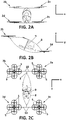
Figs. 2A-C show a front view, a side view and a plant view of the example aerial vehicle ofFig. 1 , respectively, with the four quadcopters positioned and operated to cause the aerial vehicle to hover. -
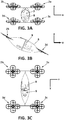
Figs. 3A-C show a front view, a side view and a plant view of the example aerial vehicle ofFig. 1 , respectively, with the four quadcopters positioned and operated to cause the aerial vehicle to cruise. -
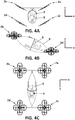
Figs. 4A-C show a front view, a side view and a plant view of the example aerial vehicle ofFig. 1 , respectively, with the four quadcopters positioned and operated to cause the aerial vehicle to hover with the downwash towards its exterior in stability mode. -
Figs. 5A-C show a front view, a side view and a plant view of the example aerial vehicle ofFig. 1 , respectively, with the four quadcopters positioned and operated to cause the aerial vehicle to move towards its right and with different thrust in its rotors. -
Fig. 6A shows a detailed view of one of the quadcopters ofFig 1 with said quadcopter pulling from the arm of the aerial vehicle (stable equilibrium).Fig. 6B shows a detailed view of one of the quadcopters ofFig 1 with said quadcopter pushing the arm of the aerial vehicle (unstable equilibrium). -
Fig. 7 shows plan schematic views of different example aerial vehicle architectures with uncoupled DOF. -
Fig. 8 shows an example spherical joint assembly to attach a particular quadcopter to an arm of the main frame of an example aerial vehicle with uncoupled DOF. -
Fig. 9 shows an example control system for managing the aerial vehicle ofFig. 1 . -
Fig. 10 shows a flow diagram of an example method for manoeuvring an aerial vehicle with uncoupled DOF. - Referring to
Fig. 1 , there is illustrated an exampleaerial vehicle 1 with uncoupled DOF having fourquadcopters 2a-d attached to an elongatedmain frame 3 by interposition ofjoints 4, for example ball joints, having three DOF. It should be understood that the exampleaerial vehicle 1 may include additional components and that some of the components described herein may be removed and/or modified without departing from a scope of the exampleaerial vehicle 1. Additionally, implementation of exampleaerial vehicle 1 is not limited to such example as shown inFIG. 1 . - The
quadcopters 2a-d are attached to themain frame 3 by interposition of thejoints 4 providing themain frame 3 with six uncoupled DOF. In particular, themain frame 3 has six DOF and each one of the ball joints 4 provides three additional CDOF such that themain frame 3 is provided with sixteen CDOF. Each one of thequadcopters 2a-d has four fixedpropulsion units 5, e.g. rotor blades, attached to respective rotor frames 6 in themain body 7 of thequadcopter 2a-d. - These
operable rotor blades 5 provide aircraft functionalities to theaerial vehicle 1. In particular, therotor blades 5 are to provide lift during vertical manoeuvring of theaerial vehicle 1 and directional thrust for horizontal displacements. In some examples, theaerial vehicle 1 may comprise a pair ofrotor blades 5 within the rotor frames 6 provided as upper and lower rotor blades, for accurate thrust control. - Each
quadcopter 2a-d, in addition to therotor blades 5, further comprises a motor (not shown), e.g. a brushless motor, associated with therotor blade 5, and a speed processing unit (not shown) to relay signals to the motors in thequadcopters 2a-d that determine how fast to spin. Alternatively, thequadcopters 2a-d may comprise a torque processing unit instead of the speed processing unit to relay signals to the motors determining how fast to spin. At any time, each one of the motors in aparticular quadcopter 2, and thus therespective rotor blades 5, could be spinning at a different speed to provide different thrusts. Alternatively, themain frame 3 may comprise a centralised speed processing unit which is in communication with each one of the motors of thequadcopters 2a-d. Such arrangements provide an excellent thrust output, thereby achieving the maximum possible lift capability for theaerial vehicle 1. While inFig. 1 , thequadcopters 2a-d compriserotor blades 5 for providing aircraft functionalities, alternative propulsion units could be envisaged, for example, in the use of propellers, turboprop engines or adjustable jet engines. - The
aerial vehicle 1 also comprises at least one controller (not shown) to operate thequadcopters 2 based on the intended direction of travel. This at least one controller operates, via the speed processing unit, therotor blades 5 by modifying their relative speed such that the position of each one of thequadcopters 2 relative to themain frame 3 can be independently modified, and therefore the thrust vector generated by each quadcopter. Thus, the at least one controller is configured to determine the relative position of each one of thequadcopters 2 independently of the relative position of the rest ofquadcopters 2 and themain frame 3 in theaerial vehicle 1. In this way, the at least one controller may determine a different setpoint (thrust and tilt angles, roll, pitch and yaw) for each one of thequadcopters 2 providing theaerial vehicle 1 with additional operation modes other than basic operation modes (these basic operation modes are those movements performed by an aerial vehicle having a common setpoint for all its multicopter units). Examples of these additional operation modes are stability modes in which multicopters are with inverse rotor angle such that forces generated by the multicopters counteract each other increasing the stability of the aircraft, precision modes due to the increased manoeuvrability of the aerial vehicle with uncoupled DOF or efficient cruising modes in which the multicopter units can be positioned in its cruising position but at the same time maintaining the capsule in a position that minimizes aerodynamic drag. - The aerial vehicle also has an
airframe body 8 attached to themain frame 3. In such example, theairframe body 8 is a capsule for transporting a user or passenger, so thecapsule 8 incorporates aseat 9 for the user. Themain frame 3 has fourarms 10 located in pairs at both ends of themain frame 3. Each one of thesearms 10 has, in proximity to their free ends, a corresponding ball joint 4 to attach therespective quadcopter 2 to themain frame 3. In some examples and depending on the geometry of themain frame 3, thearms 10 may extend from a centre of theaerial vehicle 1 to radial points of themain frame 3. - The
main frame 3 and theairframe body 8 may be releasably attached, or may be integrally formed with one another. Theairframe body 8 may also comprise a structure to carry other elements such as batteries, different kind of payloads, etc. - Although
Fig. 1 shows anaerial vehicle 1 formed by fourquadcopters 2, it will be apparent that any other suitable aerial vehicle architecture, including any number of multicopter units arranged to the main frame and any number of propulsion units arranged to each multicopter unit may be utilised to provide the multicopter functionality to theaerial vehicle 1. In addition, althoughFig. 1 shows the fourquadcopters 2 linked to themain frame 3 viaball joints 4, other kind of joints with among one and three DOF may be used. Besides, the joints may be different from each other having different number of DOF among them. In some implementations, some of the joints may be fixed joints. -
Figs. 2A-C show a front view, a side view and a plant view of the example aerial vehicle ofFig. 1 , respectively, with the four quadcopters positioned and operated to cause the aerial vehicle to hover. - In such example, the four
quadcopters 2a-d are positioned relative to themain frame 3 and operated to cause theaerial vehicle 1 to hover, i.e., to stay in the same position while airborne. In such example, thequadcopters quadcopters Fig. 2B , both planes are substantially horizontal planes parallel to each other, and the distance between both planes is such that thecapsule 8 and thus, theseat 9, is positioned in a substantially vertical position for the passenger. Thequadcopters quadcopters quadcopters 2a-d is the thrust vector necessary for maintaining theaerial vehicle 1 in equilibrium and maintaining the same position for the passenger.. In such example, the centre of gravity is centred on theaerial vehicle 1, and thus, the thrust is purely vertical. This position of thequadcopters 2a-2d relative to each other can be also used for ascending operations when the rotor thrust is increased with the same magnitude in all therotors 5 of theaerial vehicle 1 and for descending operations when the rotor thrust is decreased with the same magnitude in all therotors 5 of theaerial vehicle 1. -
Figs. 3A-C show a front view, a side view and a plant view of the example aerial vehicle ofFig. 1 , respectively, with the four quadcopters positioned and operated to cause the aerial vehicle to cruise. - In such example, the four
quadcopters 2a-d are positioned relative to themain frame 3 and operated to cause theaerial vehicle 1 to cruise, i.e., to perform a horizontal movement in a particular direction (see arrow inFig. 3B in Y-axis direction) and with the same thrust in all thequadcopters 2a-d. In such example, thequadcopters 2a-d are positioned in the same plane, said plane being at particular angle relative to the horizontal plane. The controller operates all thequadcopters 2a-d to rotate relative to theirrespective ball joints 4 such that their thrust vectors (thrust magnitude and tilt angle) relative to themain frame 3 is the same. Eventually, the thrust generated by therotors 5 may be modified depending on the cruise speed needed. In some other examples, thequadcopters 2a-d may be rotated via their respective ball joints with a different tilt angle relative to themain frame 3 such that the direction of travel may be different, e.g., thequadcopters 2a-d may left rotated with the same angle relative to themain frame 3 and the same thrust to direct theaerial vehicle 1 in such direction. -
Figs. 4A-C show a front view, a side view and a plant view of the example aerial vehicle ofFig. 1 , respectively, with the fourquadcopters 2a-d positioned and operated to cause theaerial vehicle 1 to hover and with the downwash towards its exterior in stability mode. - In such example, the
quadcopters 2a-d are all inclined the same angle towards the centre of themain frame 3. Thus, eachquadcopter 2a-d is positioned in a different plane but inclined with the same angle relative to the horizontal plane. The controller operates all thequadcopters 2a-d to rotate relative to theirrespective ball joints 4 such that their thrust magnitude is same and the tilt angle relative to the horizontal plane is the same but withquadcopters quadcopters quadcopters 2a-d to rotate relative to their respective ball joints to be positioned forming the complementary angle to that shown infigure 4 such that thequadcopters 2a-d are all inclined away from the centre of themain frame 3. In some other examples, the fourquadcopters 2a-d may be also positioned and operated to cause theaerial vehicle 1 to hover but with the downwash towards its interior. -
Figs. 5A-C show a front view, a side view and a plant view of the example aerial vehicle ofFig. 1 , respectively, with the four quadcopters positioned and operated to cause the aerial vehicle to move towards its right and with different thrust in its rotors. - In such example, the
quadcopters quadcopters quadcopters 2a-d are positioned in a different plane but are all inclined towards the same direction, in particular towards right direction (see arrow inFig. 5A in X-Z plane), to direct theaerial vehicle 1 in such direction. Therefore, the controller operates all thequadcopters 2a-d to rotate relative to theirrespective ball joints 4 with the tilt angle relative to the horizontal plane previously cited. The thrust ofquadcopters quadcopters -
Fig. 6A shows a detailed view of one of the quadcopters ofFig 1 with said quadcopter pulling from the arm of the aerial vehicle (stable equilibrium). In such example, thequadcopter 2a is positioned in an upper plane relative to thearm 10 of themain frame 3 such that thearm 10 is pulled via the ball joint 4. Therefore, the thrust (arrow up) generated by thequadcopter 2a pulls the aerial vehicle vertically and upwardly while gravity (arrow down) push theaerial vehicle 1 down.Fig. 6B shows a detailed view of one of the quadcopters ofFig 1 with said quadcopter pushing the arm of the aerial vehicle (unstable equilibrium). In such example, thequadcopter 2a is positioned in a lower plane relative to thearm 10 of themain frame 3 such that thearm 10 is being pushed via the ball joint 4. Therefore, the thrust (arrow up) generated by thequadcopter 2a pushes theaerial vehicle 1 vertically and upwardly while gravity (arrow down) push theaerial vehicle 1 down. - Although
Figs. 6A and 6B show thequadcopter 2a connected to themain frame 3 by interposition of a ball joint 4, any joint with a maximum of three DOF relative (e.g., a spherical joint) to the given rotational point and a minimum of one DOF relative to the given rotational point (e.g., a hinge joint) being in its pull or push configurations, i.e. with the joint pulling the quadcopter or with the joint being pushed by the quadcopter, could be used. Pull configuration is a more stable configuration since the equilibrium of forces (thrust and gravity) is in a stable equilibrium while the push configuration is the most unstable as the equilibrium of forces is in an unstable equilibrium. -
Fig. 7 shows plan schematic views of different example aerial vehicle architectures. In such schematic views five different architectures are shown. It should be understood that the example aerial vehicle architectures may include additional components and that some of the components described herein may be removed and/or modified without departing from a scope of the example aerial vehicle architectures. Additionally, implementation of example aerial vehicle architectures is not limited to such example as shown inFIG. 7 . - Multiple combinations between the number of multicopters and the number of propulsion units (e.g. rotors, turboprop engines, jet engines, etc.) arranged on each multicopter unit would be possible. Thus, it would be possible to combine different aerial vehicle architectures according to the following formula that gives the number of total propulsion units in the multicopter unmanned aerial vehicle:

- A first architecture a) corresponds to a bicopter of bicopters (N=2 and A=2). Thus, the
aerial vehicle 11 is formed by twobicopters 12 attached to themain frame 13 by interposition of spherical joints. In such architecture themain frame 13 may be an elongated body with the twobicopters 12 attached in proximity to its respective ends. Eachbicopter 12 hastree propulsion units 14 attached to theirrespective bodies 15. - A second architecture b) corresponds to a bicopter of tricopters (N=2 and A=3). Thus, the
aerial vehicle 16 is formed by twotricopters 17 attached to themain frame 18 by interposition of spherical joints. In such architecture themain frame 18 may be an elongated body with the twotricopters 17 attached in proximity to its respective ends. Eachtricopter 17 hastree propulsion units 19 attached to theirrespective bodies 20. - A third architecture c) corresponds to a tricopter of tricopters (N=3 and A=3). Thus, the
aerial vehicle 21 is formed by threetricopters 22 attached to themain frame 23 by interposition of spherical joints. In such architecture themain frame 23 may be a substantially triangular body with the threetricopters 22 attached in proximity to its corners. Eachtricopter 22 hastree propulsion units 24 attached to theirrespective bodies 25. - A fourth architecture d) corresponds to a quadcopter of quadcopters (N=4 and A=4). Thus, the
aerial vehicle 26 is formed by fourquadcopters 27 attached to themain frame 28 by interposition of spherical joints. In such architecture themain frame 28 may be a substantially quadrangular body with the fourquadcopters 27 attached in proximity to its respective corners. Eachquadcopter 27 has fourpropulsion units 29 attached to theirrespective bodies 30. - A fifth architecture e) corresponds to a quadcopter of tricopters (N=4 and A=3). Thus, the
aerial vehicle 31 is formed by fourtricopters 32 attached to themain frame 33 by interposition of spherical joints. In such architecture themain frame 33 may be a substantially quadrangular body with the fourtricopters 32 attached in proximity to its respective corners. Eachtricopter 32 hastree propulsion units 34 attached to theirrespective bodies 35. - In such example, all the architectures may comprise ball joints or spherical joints with three DOF to provide redundant CDOF to the aerial vehicles. Other architectures and geometries of the aerial vehicle may be envisaged. The architectures described in such example are, however, merely an indicative example multicopter unmanned aerial vehicle architectures, and may other alternative architectures and geometries be considered.
-
Fig. 8 shows an example sphericaljoint assembly 40 to attach aparticular quadcopter 48 to anarm 46 of the main frame of an example aerial vehicle with uncoupled DOF. As used herein, a spherical joint may refer to any joint that allows free rotation in two planes at the same time while preventing translation in any direction. It should be understood that the example sphericaljoint assembly 40 may include additional components and that some of the components described herein may be removed and/or modified without departing from a scope of the example sphericaljoint assembly 40. Additionally, implementation of example sphericaljoint assembly 40 is not limited to such example as shown inFIG. 8 . - In such example, the spherical
joint assembly 40 is a ball joint assembly formed by aball stud 41 and ahousing 42. Thehousing 42 has an open bore in which theball stud 41 is inserted. Theball stud 41 has ashank portion 43 and aball portion 44. Theball portion 44 has a semi-spherical shape and is received in the open bore of thehousing 42 such that theshank portion 43 projects out of the open bore. Theshank portion 43 is attached to aprotrusion 45 of thearm 46 of the main frame of the aerial vehicle. - The
housing 42 is formed in asocket portion 47 of the balljoint assembly 40. Thissocket portion 47 is coupled to the main body of thequadcopter 48. For example, screws may be used to attach the socket potion to the main body of thequadcopter 48. - This spherical
joint assembly 40 allows movements that will be determined by the sum of forces generated by thequadcopter 48 attached to it. The spherical joint assembly allows varying the relative position of the quadcopter and thus, provides the aircraft with additional mobility and independent DOF by combining the different forces generated by the plurality of multicopters attached to the main frame via the spherical joints. - In some examples, the spherical joints may incorporate mechanism to restrict one or more DOF. For example, in an aerial vehicle for transporting people it might be unnecessary to have all DOF of the spherical joint, as for example the operation mode of moving the aerial vehicle backwards at maximum speed. In this case, the spherical joint could have a mechanical system, such as a bolt or latch, to restrict the tilt backwards. The joint may further comprise a remote-control system to activate the mechanical system for restricting specific DOF. These restricting mechanisms may be also useful in operation modes where the controllability or safety requirements are higher (e.g. at landing). For example, during an emergency landing some of the DOF of the spherical joints may be blocked to maintain the spherical joints perpendicular to the ground.
- The spherical joints may also have additional elements to provide additional functionalities. For example, shock absorbing mechanisms for variable damping the forces exerted on the joint during movement of the aerial vehicle, force generation mechanisms for generating an opposing and variable force in the kneecap of the joint when making the movement and force generation mechanisms to generate a variable force to the joint when it reaches its mechanical limits (bump stop), among others.
- Thus, using joints with at least one DOF to attach the multicopter units to the main frame provides independent DOF without having to add servo-actuators to the architecture. Besides, the weight and the electronics associated to the servo-actuators is avoided at the same time that energy consumption is reduced.
-
Fig. 9 shows anexample control system 50 for managing the aerial vehicle ofFig. 1 . It should be understood that theexample control system 50 may include additional components and that some of the components described herein may be removed and/or modified without departing from a scope of theexample control system 50. Additionally, implementation ofexample control system 50 is not limited to such example as shown inFIG. 9 . - In such example, the
control system 50 comprises acontroller 51 which is communicatively coupled to a referencingprocessing unit 52 that determines displacement of themain frame 3 with respect to a horizontal plane. The referencingprocessing unit 52 may be communicatively coupled to aninertial measurement unit 53. In turn, saidinertial measurement unit 53 is also communicatively coupled a plurality ofaccelerometers 54 and/orgyroscopes 55 positioned on different locations on themain frame 3 to measure parameters such as acceleration, orientation, angular velocity, etc. As used herein, the referencingprocessing unit 52 may be any combination of software and hardware configured to perform the described functionalities of the referencing processing unit. - If the
aerial vehicle 1 is remotely controlled, thecontroller 51 may be further communicatively coupled to a transceiver configured to receive instructions from a remote control to pilot the aircraft. Alternatively, if theaerial vehicle 1 is an autonomous aircraft, the controller may be coupled to an autopilot processing unit comprising software and hardware to perform the autonomous flight. - The
controller 51 is configured to receive the current orientation of themain frame 3 from the referencingprocessing unit 52. Based on the current orientation of themain frame 3, a current thrust and the intended thrust and direction of travel, the primary controller determines a thrust magnitude for each one themotors 56 associated to the propulsion units (e.g. rotors). Thecontroller 52 sends the calculated thrusts to thespeed processing unit 57. Thespeed processing unit 57, which is in communication with each one of themotors 56 of thequadcopters 2a-d, sends the corresponding relay signals to the respective motors in thequadcopters 2a-d that will determine their rotor speed. By modifying the thrust magnitude of the different propulsion units, the position of thequadcopters 2a-d relative to themain frame 3 will be modified. - In some other examples, the control system may comprise a primary controller located in the main frame and a plurality of secondary controllers, each secondary controller being located in a corresponding multicopter unit. Besides each multicopter unit may have its own speed processing unit. With such control system architecture, the secondary controllers may be configured to operate the respective multicopter units and the primary controller may be configured to manage the plurality of secondary controllers. This primary controller may be communicatively coupled to the referencing processing unit to receive information about the orientation of the main frame while the secondary controllers may be communicatively coupled to the primary controller. In this way, the primary controller with the information about the current orientation, current direction of travel and the intended direction of travel of the aerial vehicle is able to determine a direction to be taken by the aerial vehicle. The primary controller may transmit the direction to be taken, i.e., the thrust vector for the aerial vehicle, to the secondary controllers such that each secondary controller may operate the respective multicopter unit to direct the aerial vehicle in the direction to be taken. Each secondary controller may send the calculated thrust for that particular quadcopter to the corresponding speed processing unit. The speed processing unit may send the corresponding relay signals to the respective motors in the quadcopters that will determine their rotor speed.
-
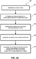
Fig. 10 shows a flow diagram of an example method for manoeuvring an aerial vehicle with uncoupled DOF. - At
step 61 of themethod 60, an aerial vehicle with uncoupled DOF as previously disclosed is provided. This aerial vehicle comprises a main frame, a plurality of multicopter units attached to the main frame by interposition of respective joints, where at least one joint has a minimum of one degree of freedom, such that the main frame has the same or a higher number of CDOF than a total number of DOF of the main frame. - At
step 62 of the method, the referencing processing unit of the aerial vehicle determines a displacement of the aerial vehicle relative to a horizontal plane. Preferably, the referencing processing unit may be communicatively coupled to an inertial measurement unit and a plurality of accelerometers and/or gyroscopes positioned on the main frame. - At
step 63 of themethod 60, a controller of the aerial vehicle determines a global thrust vector or setpoint (thrust + tilt angles, yaw, roll and pitch) for the entire aerial vehicle based on the determined displacement. Then, the controller calculates a thrust vector (thrust and a tilt angles) for each one of the plurality of multicopter units based on the global thrust vector previously calculated. - At
step 64 of themethod 60, the controller adjusts the thrust of each propulsion unit of the plurality of multicopter units based on the determined thrust. - At
step 65 of themethod 60, the controller adjusts the tilt angle of the plurality of multicopter units by performing a rotational movement of each multicopter units relative to the main frame via the joints, the relative rotational movement being based on the determined tilt angle. - Aerial vehicles with uncoupled DOF as described herein may be useful for providing scalable aircraft architectures based on minimum propulsion modules that are joined to a common structure by joints with at least one DOF and up to three DOF of rotation. These joints linking each multicopter unit to the main aircraft structure can allow up to 3 degrees of rotational freedom (X-turn, Y-turn and Z-turn) and enable the precise positioning of each of the muticopter units relative to the main aircraft structure. All these benefits enable the aircraft to perform movements that currently cannot be performed by existing aircrafts with fixed propulsion units.
- In this text, the term "comprises" and its derivations (such as "comprising", etc.) should not be understood in an excluding sense, that is, these terms should not be interpreted as excluding the possibility that what is described and defined may include further elements.
- The invention is obviously not limited to the specific embodiments described herein, but also encompasses any variations that may be considered by any person skilled in the art within the general scope of the invention as defined in the claims.
Claims (15)
- An aerial vehicle comprising:a main frame;a plurality of operable multicopter units, each multicopter unit having a plurality of propulsion units, wherein the plurality of propulsion units are attached to the multicopter unit at a fixed yaw angle, a fixed roll angle and a fixed pitch angle; andwherein the plurality of operable multicopter units are attached to the main frame by interposition of respective joints and rotate relative to the main frame independently of one another, and where at least one joint has a minimum of one degree of freedom, such that the main frame has the same or a higher number of controllable degrees of freedom than a total number of degrees of freedom of the main frame.
- The aerial vehicle according to claim 1, wherein the joints have a maximum of three degrees of freedom.
- The aerial vehicle according to any one of the preceding claims, wherein the main frame has a plurality of arms extending radially therefrom and each operable multicopter unit is attached to a corresponding arm of the plurality of arms.
- The aerial vehicle according to any one of the preceding claims, wherein the joints comprise a release system such that the plurality of operable multicopter units are releasable attached to the main frame.
- The aerial vehicle according to any one of the preceding claims, wherein the joints comprise locking means configured to restrict movement of the joints in at least one degree of freedom.
- The aerial vehicle according to any one of the preceding claims, wherein the joints comprise blocking means configured to temporarily block movement of the joints in at least one degree of freedom.
- The aerial vehicle according to any one of the preceding claims, wherein the joints comprise shock absorbing means configured to absorb shock impulses generated by the movement of the multicopter units relative to the main frame.
- The aerial vehicle according to any one of the preceding claims, wherein the joints are selected from a group comprising spherical joints, cardan joints, ball joints, constant velocity joints and any combination thereof.
- The aerial vehicle according to claim 1, wherein the plurality of operable multicopter units are equidistantly located relative to a central point of the main frame.
- The aerial vehicle according to any one of the preceding claims, comprising a referencing processing unit located on the main frame and configured to determine a displacement of the main frame relative to a horizontal plane.
- The aerial vehicle according to any one of the preceding claims, comprising a controller located in the main frame configured to operate of the plurality of multicopter units.
- The aerial vehicle according to any one of the preceding claims, comprising:a primary controller located in the main frame; anda plurality of secondary controllers, each secondary controller being located in a corresponding multicopter unit;wherein the plurality of secondary controllers is configured to operate the respective multicopter units and the primary controller is configured to manage the plurality of secondary controllers.
- A method for manoeuvring an aerial vehicle, comprising:providing an aerial vehicle as claimed in any one of the preceding claims;determining, by the referencing processing unit, a displacement of the aerial vehicle relative to a horizontal plane;determining, by a controller of the aerial vehicle, a thrust and a tilt angle for the aerial vehicle based on the determined displacement;adjusting, by the controller, the thrust of each one of the plurality of multicopter units based on the determined thrust; andadjusting, by the controller, the tilt angle of each one the plurality of multicopter units by performing a rotational movement of each multicopter unit relative to the main frame via the joints, the relative rotational movement being based on the determined tilt angle.
- The method according to claim 13, wherein the aerial vehicle has a primary controller attached to the main frame and a secondary controller attached to each multicopter unit, wherein the plurality of secondary controllers are to operate the respective multicopter units and the primary controller is to manage the plurality of secondary controllers, the method comprising:determining, by the primary controller, the thrust and the tilt angle for the aerial vehicle based on the determined displacement;adjusting, by each secondary controller, the thrust of the respective multicopter unit based on the determined thrust; andadjusting, by each secondary controller, the tilt angle of the respective multicopter unit by performing a rotational movement of the multicopter unit relative to the main frame via the joints, the relative rotational movement being based on the determined tilt angle.
- The method according to claim 13, wherein the aerial vehicle has a plurality of controllers configured to operate the plurality of multicopter units, the method comprising:determining, by any one of the plurality of controllers, the thrust and the tilt angle for the aerial vehicle based on the determined displacement;adjusting, by any one of the plurality of controllers, the thrust of the plurality of multicopter units based on the determined thrust; andadjusting, by any one of the plurality of controllers, the tilt angle of the plurality of multicopter units by performing a rotational movement of the multicopter units relative to the main frame via the joints, the relative rotational movement being based on the determined tilt angle.
Priority Applications (16)
| Application Number | Priority Date | Filing Date | Title |
|---|---|---|---|
| HRP20220528TT HRP20220528T1 (en) | 2018-11-30 | 2018-11-30 | Aerial vehicles with uncoupled degrees of freedom |
| ES18382880T ES2912732T3 (en) | 2018-11-30 | 2018-11-30 | Aerial vehicles with decoupled degrees of freedom |
| EP18382880.5A EP3659912B8 (en) | 2018-11-30 | 2018-11-30 | Aerial vehicles with uncoupled degrees of freedom |
| DK18382880.5T DK3659912T3 (en) | 2018-11-30 | 2018-11-30 | Aircraft with decoupled degrees of freedom |
| RU2021115298A RU2769822C1 (en) | 2018-11-30 | 2019-11-20 | Aircraft with unrelated degrees of freedom |
| IL283535A IL283535B2 (en) | 2018-11-30 | 2019-11-20 | Aerial vehicles with uncoupled degrees of freedom |
| CA3121336A CA3121336A1 (en) | 2018-11-30 | 2019-11-20 | Aerial vehicles with uncoupled degrees of freedom |
| CN201980087054.7A CN113260565B (en) | 2018-11-30 | 2019-11-20 | Aircraft with decoupled degrees of freedom |
| JP2021531319A JP7443365B2 (en) | 2018-11-30 | 2019-11-20 | Aircraft with separate degrees of freedom |
| AU2019387201A AU2019387201B2 (en) | 2018-11-30 | 2019-11-20 | Aerial vehicles with uncoupled degrees of freedom |
| SG11202105677QA SG11202105677QA (en) | 2018-11-30 | 2019-11-20 | Aerial vehicles with uncoupled degrees of freedom |
| BR112021010419-4A BR112021010419B1 (en) | 2018-11-30 | 2019-11-20 | AIR VEHICLES WITH UNCOUPLED DEGREES OF FREEDOM |
| MX2021006261A MX2021006261A (en) | 2018-11-30 | 2019-11-20 | Aerial vehicles with uncoupled degrees of freedom. |
| PCT/EP2019/081888 WO2020109100A1 (en) | 2018-11-30 | 2019-11-20 | Aerial vehicles with uncoupled degrees of freedom |
| KR1020217019864A KR20220034024A (en) | 2018-11-30 | 2019-11-20 | AERIAL VEHICLES WITH UNCOUPLED DEGREES OF FREEDOM |
| US17/298,099 US12037109B2 (en) | 2018-11-30 | 2019-11-20 | Aerial vehicles with uncoupled degrees of freedom |
Applications Claiming Priority (1)
| Application Number | Priority Date | Filing Date | Title |
|---|---|---|---|
| EP18382880.5A EP3659912B8 (en) | 2018-11-30 | 2018-11-30 | Aerial vehicles with uncoupled degrees of freedom |
Publications (3)
| Publication Number | Publication Date |
|---|---|
| EP3659912A1 true EP3659912A1 (en) | 2020-06-03 |
| EP3659912B1 EP3659912B1 (en) | 2022-01-26 |
| EP3659912B8 EP3659912B8 (en) | 2023-01-11 |
Family
ID=64665093
Family Applications (1)
| Application Number | Title | Priority Date | Filing Date |
|---|---|---|---|
| EP18382880.5A Active EP3659912B8 (en) | 2018-11-30 | 2018-11-30 | Aerial vehicles with uncoupled degrees of freedom |
Country Status (15)
| Country | Link |
|---|---|
| US (1) | US12037109B2 (en) |
| EP (1) | EP3659912B8 (en) |
| JP (1) | JP7443365B2 (en) |
| KR (1) | KR20220034024A (en) |
| CN (1) | CN113260565B (en) |
| AU (1) | AU2019387201B2 (en) |
| CA (1) | CA3121336A1 (en) |
| DK (1) | DK3659912T3 (en) |
| ES (1) | ES2912732T3 (en) |
| HR (1) | HRP20220528T1 (en) |
| IL (1) | IL283535B2 (en) |
| MX (1) | MX2021006261A (en) |
| RU (1) | RU2769822C1 (en) |
| SG (1) | SG11202105677QA (en) |
| WO (1) | WO2020109100A1 (en) |
Cited By (3)
| Publication number | Priority date | Publication date | Assignee | Title |
|---|---|---|---|---|
| CN112977793A (en) * | 2021-04-19 | 2021-06-18 | 深圳市科卫泰实业发展有限公司 | Combined multi-rotor unmanned aerial vehicle and control method thereof |
| WO2023101540A1 (en) * | 2021-12-03 | 2023-06-08 | 디스이즈엔지니어링주식회사 | Aerial vehicle |
| WO2024164048A1 (en) * | 2023-02-08 | 2024-08-15 | Alauda Aeronautics Pty Ltd | Vtol aerial vehicle with gimballed ducted propulsion units |
Families Citing this family (11)
| Publication number | Priority date | Publication date | Assignee | Title |
|---|---|---|---|---|
| GB2583971A (en) * | 2019-05-16 | 2020-11-18 | Autonomous Devices Ltd | Control arrangement for fluid borne vehicles |
| US12434682B1 (en) * | 2019-11-26 | 2025-10-07 | Owen Richard Wiseman | Hover drone system |
| DE102020120571B4 (en) * | 2020-08-04 | 2024-05-16 | Volocopter Gmbh | Method for determining a manoeuvring reserve in an aircraft, flight control device in an aircraft and correspondingly equipped aircraft |
| WO2022242458A1 (en) * | 2021-05-15 | 2022-11-24 | 余新克 | Multi-layer swing rotor reaction force strong wind-resistant aircraft |
| KR20230120915A (en) | 2022-02-10 | 2023-08-17 | 디스이즈엔지니어링 주식회사 | Air vehicle |
| WO2023164004A1 (en) * | 2022-02-22 | 2023-08-31 | Arizona Board Of Regents On Behalf Of The University Of Arizona | Configurable unmanned aerial vehicle system |
| EP4269239A1 (en) * | 2022-04-25 | 2023-11-01 | Fundación Tecnalia Research & Innovation | Omnidirectional vehicle with passive revolute joints |
| JP7621316B2 (en) * | 2022-09-14 | 2025-01-24 | 双葉電子工業株式会社 | Control device, flying vehicle system |
| WO2024178095A2 (en) * | 2023-02-21 | 2024-08-29 | Arizona Board Of Regents On Behalf Of The University Of Arizona | Control system for a configurable unmanned aerial vehicle system |
| FR3148003B1 (en) * | 2023-04-20 | 2026-01-30 | Aeronde | Aircraft |
| US12404911B1 (en) | 2024-12-06 | 2025-09-02 | Samanth Mottera Srinivas | Turboshaft engine powered quadrotor drone |
Citations (4)
| Publication number | Priority date | Publication date | Assignee | Title |
|---|---|---|---|---|
| US20060016930A1 (en) * | 2004-07-09 | 2006-01-26 | Steve Pak | Sky hopper |
| WO2017183551A1 (en) * | 2016-04-19 | 2017-10-26 | 株式会社プロドローン | Unmanned aerial vehicle |
| US20180148169A1 (en) * | 2016-11-28 | 2018-05-31 | Advance Technology Holdings, L.L.C. | Unmanned Aerial Vehicle With Omnidirectional Thrust Vectoring |
| WO2018106137A2 (en) * | 2016-11-17 | 2018-06-14 | Liviu Grigorian Giurca | Distributed electric propulsion system and vertical take-off and landing aircraft |
Family Cites Families (20)
| Publication number | Priority date | Publication date | Assignee | Title |
|---|---|---|---|---|
| JP2001039397A (en) * | 1999-08-02 | 2001-02-13 | Komatsu Ltd | Flying body having horizontal rotary wing |
| JP2005206015A (en) | 2004-01-22 | 2005-08-04 | Toyota Motor Corp | Attitude control device for vertical take-off and landing aircraft |
| DE102006019300B4 (en) | 2006-04-26 | 2009-10-08 | Reinhardt, Gaby Traute | plane |
| DE102008014853B4 (en) | 2008-03-18 | 2010-11-18 | Ascending Technologies Gmbh | Rotary-wing aircraft |
| US20100044499A1 (en) | 2008-08-22 | 2010-02-25 | Draganfly Innovations Inc. | Six rotor helicopter |
| IL213180A0 (en) * | 2011-05-26 | 2011-10-31 | Poni Aharon Oz | Aircraft |
| SG194241A1 (en) * | 2012-04-11 | 2013-11-29 | Singapore Tech Aerospace Ltd | A rotor-arm assembly and a multi-rotorcraft |
| RU2532448C1 (en) * | 2013-04-10 | 2014-11-10 | Открытое акционерное общество "Долгопрудненское конструкторское бюро автоматики" | Method of control, stabilisation and development of extra lift of airship |
| RU2547950C1 (en) * | 2013-12-19 | 2015-04-10 | Общество с ограниченной ответственностью научно-производственное предприятие "Измерон-В" (ООО НПП "Измерон-В") | Quadrocopter |
| US20160272310A1 (en) * | 2014-12-04 | 2016-09-22 | Elwha Llc | Reconfigurable unmanned aircraft system |
| US9630712B1 (en) * | 2015-09-23 | 2017-04-25 | Amazon Technologies, Inc. | Using multirotor lifters to deploy fixed wing aircraft |
| KR102385014B1 (en) | 2016-12-22 | 2022-04-12 | 키티 호크 코포레이션 | Distributed flight control system |
| EP3366582B1 (en) * | 2017-02-28 | 2019-07-24 | AIRBUS HELICOPTERS DEUTSCHLAND GmbH | A multirotor aircraft with an airframe and a thrust producing units arrangement |
| IL256941A (en) | 2018-01-15 | 2018-03-29 | Colugo Systems Ltd | A free-wing multi-blade that includes vertical and horizontal engines |
| KR101884673B1 (en) * | 2017-03-15 | 2018-08-02 | 주식회사 넥스컴스 | Combined large multi-copter |
| US10745129B2 (en) | 2017-04-27 | 2020-08-18 | Timothy J. NEAR | Multirotor vehicle |
| JP6550563B2 (en) | 2018-04-10 | 2019-07-31 | 株式会社エアロネクスト | Rotorcraft |
| JP7085892B2 (en) * | 2018-05-14 | 2022-06-17 | 川崎重工業株式会社 | Aircraft and how to control the aircraft |
| US11130568B2 (en) * | 2018-11-08 | 2021-09-28 | Textron Innovations Inc. | Autonomous thrust vectoring ring wing pod |
| JP7185498B2 (en) * | 2018-11-12 | 2022-12-07 | 株式会社Subaru | Rotorcraft and method of controlling rotorcraft |
-
2018
- 2018-11-30 DK DK18382880.5T patent/DK3659912T3/en active
- 2018-11-30 EP EP18382880.5A patent/EP3659912B8/en active Active
- 2018-11-30 HR HRP20220528TT patent/HRP20220528T1/en unknown
- 2018-11-30 ES ES18382880T patent/ES2912732T3/en active Active
-
2019
- 2019-11-20 WO PCT/EP2019/081888 patent/WO2020109100A1/en not_active Ceased
- 2019-11-20 JP JP2021531319A patent/JP7443365B2/en active Active
- 2019-11-20 CN CN201980087054.7A patent/CN113260565B/en active Active
- 2019-11-20 MX MX2021006261A patent/MX2021006261A/en unknown
- 2019-11-20 AU AU2019387201A patent/AU2019387201B2/en active Active
- 2019-11-20 KR KR1020217019864A patent/KR20220034024A/en active Pending
- 2019-11-20 US US17/298,099 patent/US12037109B2/en active Active
- 2019-11-20 CA CA3121336A patent/CA3121336A1/en active Pending
- 2019-11-20 SG SG11202105677QA patent/SG11202105677QA/en unknown
- 2019-11-20 RU RU2021115298A patent/RU2769822C1/en active
- 2019-11-20 IL IL283535A patent/IL283535B2/en unknown
Patent Citations (4)
| Publication number | Priority date | Publication date | Assignee | Title |
|---|---|---|---|---|
| US20060016930A1 (en) * | 2004-07-09 | 2006-01-26 | Steve Pak | Sky hopper |
| WO2017183551A1 (en) * | 2016-04-19 | 2017-10-26 | 株式会社プロドローン | Unmanned aerial vehicle |
| WO2018106137A2 (en) * | 2016-11-17 | 2018-06-14 | Liviu Grigorian Giurca | Distributed electric propulsion system and vertical take-off and landing aircraft |
| US20180148169A1 (en) * | 2016-11-28 | 2018-05-31 | Advance Technology Holdings, L.L.C. | Unmanned Aerial Vehicle With Omnidirectional Thrust Vectoring |
Cited By (3)
| Publication number | Priority date | Publication date | Assignee | Title |
|---|---|---|---|---|
| CN112977793A (en) * | 2021-04-19 | 2021-06-18 | 深圳市科卫泰实业发展有限公司 | Combined multi-rotor unmanned aerial vehicle and control method thereof |
| WO2023101540A1 (en) * | 2021-12-03 | 2023-06-08 | 디스이즈엔지니어링주식회사 | Aerial vehicle |
| WO2024164048A1 (en) * | 2023-02-08 | 2024-08-15 | Alauda Aeronautics Pty Ltd | Vtol aerial vehicle with gimballed ducted propulsion units |
Also Published As
| Publication number | Publication date |
|---|---|
| CN113260565B (en) | 2025-02-28 |
| WO2020109100A1 (en) | 2020-06-04 |
| JP7443365B2 (en) | 2024-03-05 |
| IL283535B2 (en) | 2026-04-01 |
| AU2019387201A1 (en) | 2021-06-17 |
| MX2021006261A (en) | 2021-08-05 |
| HRP20220528T1 (en) | 2022-05-27 |
| EP3659912B8 (en) | 2023-01-11 |
| SG11202105677QA (en) | 2021-06-29 |
| JP2022509697A (en) | 2022-01-21 |
| US12037109B2 (en) | 2024-07-16 |
| EP3659912B1 (en) | 2022-01-26 |
| IL283535A (en) | 2021-07-29 |
| BR112021010419A2 (en) | 2021-08-24 |
| KR20220034024A (en) | 2022-03-17 |
| IL283535B1 (en) | 2025-12-01 |
| US20220001976A1 (en) | 2022-01-06 |
| ES2912732T3 (en) | 2022-05-27 |
| DK3659912T3 (en) | 2022-04-25 |
| CA3121336A1 (en) | 2020-06-04 |
| RU2769822C1 (en) | 2022-04-06 |
| CN113260565A (en) | 2021-08-13 |
| AU2019387201B2 (en) | 2025-08-14 |
Similar Documents
| Publication | Publication Date | Title |
|---|---|---|
| AU2019387201B2 (en) | Aerial vehicles with uncoupled degrees of freedom | |
| US11649061B2 (en) | Aircraft having multiple independent yaw authority mechanisms | |
| EP3725680B1 (en) | Multimodal unmanned aerial systems having tiltable wings | |
| US10913541B2 (en) | Aircraft having redundant directional control | |
| US10737765B2 (en) | Aircraft having single-axis gimbal mounted propulsion systems | |
| US10737778B2 (en) | Two-axis gimbal mounted propulsion systems for aircraft | |
| US10196138B2 (en) | Self-tightening rotor | |
| CN108238244B (en) | Unmanned aerial vehicle with omnidirectional vector propulsion system, control system and control method | |
| JP2010254264A (en) | Unmanned aircraft landing and departing perpendicularly by tilt wing mechanism | |
| NL2017971A (en) | Unmanned aerial vehicle | |
| US20230264813A1 (en) | Telescoping Tail Assemblies for Use on Aircraft | |
| GB2553604B (en) | Aerodynamically fully actuated drone (Sauceron) and drone chassis aerodynamic supporting trusses (Lings) | |
| EP4151525B1 (en) | Convertible staggerwing aircraft having optimized hover power | |
| US11530035B2 (en) | VTOL aircraft having multiple wing planforms | |
| Stone | Modelling and control of a tandem-wing tail-sitter UAV | |
| BR112021010419B1 (en) | AIR VEHICLES WITH UNCOUPLED DEGREES OF FREEDOM | |
| RU196085U1 (en) | UAV VERTICAL TAKEOFF AND LANDING | |
| CA3077962A1 (en) | Multimodal unmanned aerial systems having tiltable wings |
Legal Events
| Date | Code | Title | Description |
|---|---|---|---|
| REG | Reference to a national code |
Ref country code: HR Ref legal event code: TUEP Ref document number: P20220528 Country of ref document: HR |
|
| PUAI | Public reference made under article 153(3) epc to a published international application that has entered the european phase |
Free format text: ORIGINAL CODE: 0009012 |
|
| STAA | Information on the status of an ep patent application or granted ep patent |
Free format text: STATUS: THE APPLICATION HAS BEEN PUBLISHED |
|
| AK | Designated contracting states |
Kind code of ref document: A1 Designated state(s): AL AT BE BG CH CY CZ DE DK EE ES FI FR GB GR HR HU IE IS IT LI LT LU LV MC MK MT NL NO PL PT RO RS SE SI SK SM TR |
|
| AX | Request for extension of the european patent |
Extension state: BA ME |
|
| STAA | Information on the status of an ep patent application or granted ep patent |
Free format text: STATUS: REQUEST FOR EXAMINATION WAS MADE |
|
| 17P | Request for examination filed |
Effective date: 20201201 |
|
| RBV | Designated contracting states (corrected) |
Designated state(s): AL AT BE BG CH CY CZ DE DK EE ES FI FR GB GR HR HU IE IS IT LI LT LU LV MC MK MT NL NO PL PT RO RS SE SI SK SM TR |
|
| GRAP | Despatch of communication of intention to grant a patent |
Free format text: ORIGINAL CODE: EPIDOSNIGR1 |
|
| STAA | Information on the status of an ep patent application or granted ep patent |
Free format text: STATUS: GRANT OF PATENT IS INTENDED |
|
| INTG | Intention to grant announced |
Effective date: 20210521 |
|
| GRAS | Grant fee paid |
Free format text: ORIGINAL CODE: EPIDOSNIGR3 |
|
| GRAA | (expected) grant |
Free format text: ORIGINAL CODE: 0009210 |
|
| STAA | Information on the status of an ep patent application or granted ep patent |
Free format text: STATUS: THE PATENT HAS BEEN GRANTED |
|
| AK | Designated contracting states |
Kind code of ref document: B1 Designated state(s): AL AT BE BG CH CY CZ DE DK EE ES FI FR GB GR HR HU IE IS IT LI LT LU LV MC MK MT NL NO PL PT RO RS SE SI SK SM TR |
|
| RAP1 | Party data changed (applicant data changed or rights of an application transferred) |
Owner name: UMILES URBAN AIR MOBILITY, S.L |
|
| REG | Reference to a national code |
Ref country code: GB Ref legal event code: FG4D |
|
| REG | Reference to a national code |
Ref country code: CH Ref legal event code: EP |
|
| REG | Reference to a national code |
Ref country code: DE Ref legal event code: R096 Ref document number: 602018030036 Country of ref document: DE |
|
| REG | Reference to a national code |
Ref country code: AT Ref legal event code: REF Ref document number: 1465095 Country of ref document: AT Kind code of ref document: T Effective date: 20220215 |
|
| REG | Reference to a national code |
Ref country code: IE Ref legal event code: FG4D |
|
| REG | Reference to a national code |
Ref country code: DK Ref legal event code: T3 Effective date: 20220422 |
|
| REG | Reference to a national code |
Ref country code: FI Ref legal event code: FGE |
|
| REG | Reference to a national code |
Ref country code: NL Ref legal event code: FP |
|
| REG | Reference to a national code |
Ref country code: SE Ref legal event code: TRGR |
|
| REG | Reference to a national code |
Ref country code: LT Ref legal event code: MG9D |
|
| REG | Reference to a national code |
Ref country code: HR Ref legal event code: T1PR Ref document number: P20220528 Country of ref document: HR |
|
| REG | Reference to a national code |
Ref country code: GR Ref legal event code: EP Ref document number: 20220400894 Country of ref document: GR Effective date: 20220509 |
|
| REG | Reference to a national code |
Ref country code: AT Ref legal event code: MK05 Ref document number: 1465095 Country of ref document: AT Kind code of ref document: T Effective date: 20220126 |
|
| REG | Reference to a national code |
Ref country code: NO Ref legal event code: T2 Effective date: 20220126 |
|
| PG25 | Lapsed in a contracting state [announced via postgrant information from national office to epo] |
Ref country code: RS Free format text: LAPSE BECAUSE OF FAILURE TO SUBMIT A TRANSLATION OF THE DESCRIPTION OR TO PAY THE FEE WITHIN THE PRESCRIBED TIME-LIMIT Effective date: 20220126 Ref country code: PT Free format text: LAPSE BECAUSE OF FAILURE TO SUBMIT A TRANSLATION OF THE DESCRIPTION OR TO PAY THE FEE WITHIN THE PRESCRIBED TIME-LIMIT Effective date: 20220526 Ref country code: LT Free format text: LAPSE BECAUSE OF FAILURE TO SUBMIT A TRANSLATION OF THE DESCRIPTION OR TO PAY THE FEE WITHIN THE PRESCRIBED TIME-LIMIT Effective date: 20220126 Ref country code: BG Free format text: LAPSE BECAUSE OF FAILURE TO SUBMIT A TRANSLATION OF THE DESCRIPTION OR TO PAY THE FEE WITHIN THE PRESCRIBED TIME-LIMIT Effective date: 20220426 |
|
| PG25 | Lapsed in a contracting state [announced via postgrant information from national office to epo] |
Ref country code: PL Free format text: LAPSE BECAUSE OF FAILURE TO SUBMIT A TRANSLATION OF THE DESCRIPTION OR TO PAY THE FEE WITHIN THE PRESCRIBED TIME-LIMIT Effective date: 20220126 Ref country code: LV Free format text: LAPSE BECAUSE OF FAILURE TO SUBMIT A TRANSLATION OF THE DESCRIPTION OR TO PAY THE FEE WITHIN THE PRESCRIBED TIME-LIMIT Effective date: 20220126 Ref country code: AT Free format text: LAPSE BECAUSE OF FAILURE TO SUBMIT A TRANSLATION OF THE DESCRIPTION OR TO PAY THE FEE WITHIN THE PRESCRIBED TIME-LIMIT Effective date: 20220126 |
|
| REG | Reference to a national code |
Ref country code: DE Ref legal event code: R097 Ref document number: 602018030036 Country of ref document: DE |
|
| PG25 | Lapsed in a contracting state [announced via postgrant information from national office to epo] |
Ref country code: SM Free format text: LAPSE BECAUSE OF FAILURE TO SUBMIT A TRANSLATION OF THE DESCRIPTION OR TO PAY THE FEE WITHIN THE PRESCRIBED TIME-LIMIT Effective date: 20220126 Ref country code: SK Free format text: LAPSE BECAUSE OF FAILURE TO SUBMIT A TRANSLATION OF THE DESCRIPTION OR TO PAY THE FEE WITHIN THE PRESCRIBED TIME-LIMIT Effective date: 20220126 Ref country code: RO Free format text: LAPSE BECAUSE OF FAILURE TO SUBMIT A TRANSLATION OF THE DESCRIPTION OR TO PAY THE FEE WITHIN THE PRESCRIBED TIME-LIMIT Effective date: 20220126 Ref country code: EE Free format text: LAPSE BECAUSE OF FAILURE TO SUBMIT A TRANSLATION OF THE DESCRIPTION OR TO PAY THE FEE WITHIN THE PRESCRIBED TIME-LIMIT Effective date: 20220126 |
|
| PG25 | Lapsed in a contracting state [announced via postgrant information from national office to epo] |
Ref country code: AL Free format text: LAPSE BECAUSE OF FAILURE TO SUBMIT A TRANSLATION OF THE DESCRIPTION OR TO PAY THE FEE WITHIN THE PRESCRIBED TIME-LIMIT Effective date: 20220126 |
|
| PLAA | Information modified related to event that no opposition was filed |
Free format text: ORIGINAL CODE: 0009299DELT |
|
| PLBE | No opposition filed within time limit |
Free format text: ORIGINAL CODE: 0009261 |
|
| STAA | Information on the status of an ep patent application or granted ep patent |
Free format text: STATUS: NO OPPOSITION FILED WITHIN TIME LIMIT |
|
| REG | Reference to a national code |
Ref country code: HR Ref legal event code: ODRP Ref document number: P20220528 Country of ref document: HR Payment date: 20221103 Year of fee payment: 5 |
|
| REG | Reference to a national code |
Ref country code: CH Ref legal event code: PK Free format text: BERICHTIGUNG B8 |
|
| R26N | No opposition filed (corrected) |
Effective date: 20221027 |
|
| RAP2 | Party data changed (patent owner data changed or rights of a patent transferred) |
Owner name: UMILES URBAN AIR MOBILITY, S.L Owner name: FUNDACION TECNALIA RESEARCH & INNOVATION |
|
| PG25 | Lapsed in a contracting state [announced via postgrant information from national office to epo] |
Ref country code: SI Free format text: LAPSE BECAUSE OF FAILURE TO SUBMIT A TRANSLATION OF THE DESCRIPTION OR TO PAY THE FEE WITHIN THE PRESCRIBED TIME-LIMIT Effective date: 20220126 |
|
| PG25 | Lapsed in a contracting state [announced via postgrant information from national office to epo] |
Ref country code: MC Free format text: LAPSE BECAUSE OF FAILURE TO SUBMIT A TRANSLATION OF THE DESCRIPTION OR TO PAY THE FEE WITHIN THE PRESCRIBED TIME-LIMIT Effective date: 20220126 |
|
| PG25 | Lapsed in a contracting state [announced via postgrant information from national office to epo] |
Ref country code: LU Free format text: LAPSE BECAUSE OF NON-PAYMENT OF DUE FEES Effective date: 20221130 |
|
| REG | Reference to a national code |
Ref country code: HR Ref legal event code: ODRP Ref document number: P20220528 Country of ref document: HR Payment date: 20231106 Year of fee payment: 6 |
|
| PG25 | Lapsed in a contracting state [announced via postgrant information from national office to epo] |
Ref country code: HU Free format text: LAPSE BECAUSE OF FAILURE TO SUBMIT A TRANSLATION OF THE DESCRIPTION OR TO PAY THE FEE WITHIN THE PRESCRIBED TIME-LIMIT; INVALID AB INITIO Effective date: 20181130 |
|
| PG25 | Lapsed in a contracting state [announced via postgrant information from national office to epo] |
Ref country code: CY Free format text: LAPSE BECAUSE OF FAILURE TO SUBMIT A TRANSLATION OF THE DESCRIPTION OR TO PAY THE FEE WITHIN THE PRESCRIBED TIME-LIMIT Effective date: 20220126 |
|
| PG25 | Lapsed in a contracting state [announced via postgrant information from national office to epo] |
Ref country code: MK Free format text: LAPSE BECAUSE OF FAILURE TO SUBMIT A TRANSLATION OF THE DESCRIPTION OR TO PAY THE FEE WITHIN THE PRESCRIBED TIME-LIMIT Effective date: 20220126 |
|
| PG25 | Lapsed in a contracting state [announced via postgrant information from national office to epo] |
Ref country code: MT Free format text: LAPSE BECAUSE OF FAILURE TO SUBMIT A TRANSLATION OF THE DESCRIPTION OR TO PAY THE FEE WITHIN THE PRESCRIBED TIME-LIMIT Effective date: 20220126 |
|
| REG | Reference to a national code |
Ref country code: DE Ref legal event code: R081 Ref document number: 602018030036 Country of ref document: DE Owner name: CRISALION MOBILITY, S.L.U., ES Free format text: FORMER OWNER: UMILES URBAN AIR MOBILITY, S.L, BILBAO, (BIZKAIA), ES |
|
| REG | Reference to a national code |
Ref country code: NL Ref legal event code: HC Owner name: CRISALION MOBILITY S.L.; ES Free format text: DETAILS ASSIGNMENT: CHANGE OF OWNER(S), CHANGE OF OWNER(S) NAME; FORMER OWNER NAME: UMILES URBAN AIR MOBILITY, S.L Effective date: 20241031 |
|
| REG | Reference to a national code |
Ref country code: HR Ref legal event code: ODRP Ref document number: P20220528 Country of ref document: HR Payment date: 20241031 Year of fee payment: 7 |
|
| REG | Reference to a national code |
Ref country code: HR Ref legal event code: ODRP Ref document number: P20220528 Country of ref document: HR Payment date: 20251103 Year of fee payment: 8 |
|
| PG25 | Lapsed in a contracting state [announced via postgrant information from national office to epo] |
Ref country code: TR Free format text: LAPSE BECAUSE OF FAILURE TO SUBMIT A TRANSLATION OF THE DESCRIPTION OR TO PAY THE FEE WITHIN THE PRESCRIBED TIME-LIMIT Effective date: 20220126 |
|
| PGFP | Annual fee paid to national office [announced via postgrant information from national office to epo] |
Ref country code: NL Payment date: 20251127 Year of fee payment: 8 |
|
| PGFP | Annual fee paid to national office [announced via postgrant information from national office to epo] |
Ref country code: IS Payment date: 20251124 Year of fee payment: 8 |
|
| REG | Reference to a national code |
Ref country code: CH Ref legal event code: U11 Free format text: ST27 STATUS EVENT CODE: U-0-0-U10-U11 (AS PROVIDED BY THE NATIONAL OFFICE) Effective date: 20260108 |
|
| PGFP | Annual fee paid to national office [announced via postgrant information from national office to epo] |
Ref country code: GB Payment date: 20251007 Year of fee payment: 8 |
|
| PGFP | Annual fee paid to national office [announced via postgrant information from national office to epo] |
Ref country code: NO Payment date: 20251009 Year of fee payment: 8 |
|
| PGFP | Annual fee paid to national office [announced via postgrant information from national office to epo] |
Ref country code: IT Payment date: 20251126 Year of fee payment: 8 Ref country code: FI Payment date: 20251126 Year of fee payment: 8 Ref country code: DK Payment date: 20251007 Year of fee payment: 8 |
|
| PGFP | Annual fee paid to national office [announced via postgrant information from national office to epo] |
Ref country code: HR Payment date: 20251103 Year of fee payment: 8 Ref country code: FR Payment date: 20251007 Year of fee payment: 8 |
|
| PGFP | Annual fee paid to national office [announced via postgrant information from national office to epo] |
Ref country code: GR Payment date: 20251126 Year of fee payment: 8 Ref country code: BE Payment date: 20251127 Year of fee payment: 8 |
|
| PGFP | Annual fee paid to national office [announced via postgrant information from national office to epo] |
Ref country code: SE Payment date: 20251007 Year of fee payment: 8 |
|
| PGFP | Annual fee paid to national office [announced via postgrant information from national office to epo] |
Ref country code: IE Payment date: 20251007 Year of fee payment: 8 Ref country code: CZ Payment date: 20251120 Year of fee payment: 8 |
|
| PGFP | Annual fee paid to national office [announced via postgrant information from national office to epo] |
Ref country code: ES Payment date: 20251201 Year of fee payment: 8 |
|
| PGFP | Annual fee paid to national office [announced via postgrant information from national office to epo] |
Ref country code: DE Payment date: 20251224 Year of fee payment: 8 |
|
| PGFP | Annual fee paid to national office [announced via postgrant information from national office to epo] |
Ref country code: CH Payment date: 20260108 Year of fee payment: 8 |