EP3659888A1 - Driving force distribution control device - Google Patents
Driving force distribution control device Download PDFInfo
- Publication number
- EP3659888A1 EP3659888A1 EP19208787.2A EP19208787A EP3659888A1 EP 3659888 A1 EP3659888 A1 EP 3659888A1 EP 19208787 A EP19208787 A EP 19208787A EP 3659888 A1 EP3659888 A1 EP 3659888A1
- Authority
- EP
- European Patent Office
- Prior art keywords
- vehicle
- crosswind
- driving force
- control unit
- yaw moment
- Prior art date
- Legal status (The legal status is an assumption and is not a legal conclusion. Google has not performed a legal analysis and makes no representation as to the accuracy of the status listed.)
- Withdrawn
Links
Images




Classifications
-
- B—PERFORMING OPERATIONS; TRANSPORTING
- B60—VEHICLES IN GENERAL
- B60K—ARRANGEMENT OR MOUNTING OF PROPULSION UNITS OR OF TRANSMISSIONS IN VEHICLES; ARRANGEMENT OR MOUNTING OF PLURAL DIVERSE PRIME-MOVERS IN VEHICLES; AUXILIARY DRIVES FOR VEHICLES; INSTRUMENTATION OR DASHBOARDS FOR VEHICLES; ARRANGEMENTS IN CONNECTION WITH COOLING, AIR INTAKE, GAS EXHAUST OR FUEL SUPPLY OF PROPULSION UNITS IN VEHICLES
- B60K23/00—Arrangement or mounting of control devices for vehicle transmissions, or parts thereof, not otherwise provided for
- B60K23/04—Arrangement or mounting of control devices for vehicle transmissions, or parts thereof, not otherwise provided for for differential gearing
-
- B—PERFORMING OPERATIONS; TRANSPORTING
- B60—VEHICLES IN GENERAL
- B60K—ARRANGEMENT OR MOUNTING OF PROPULSION UNITS OR OF TRANSMISSIONS IN VEHICLES; ARRANGEMENT OR MOUNTING OF PLURAL DIVERSE PRIME-MOVERS IN VEHICLES; AUXILIARY DRIVES FOR VEHICLES; INSTRUMENTATION OR DASHBOARDS FOR VEHICLES; ARRANGEMENTS IN CONNECTION WITH COOLING, AIR INTAKE, GAS EXHAUST OR FUEL SUPPLY OF PROPULSION UNITS IN VEHICLES
- B60K17/00—Arrangement or mounting of transmissions in vehicles
- B60K17/34—Arrangement or mounting of transmissions in vehicles for driving both front and rear wheels, e.g. four wheel drive vehicles
-
- B—PERFORMING OPERATIONS; TRANSPORTING
- B60—VEHICLES IN GENERAL
- B60K—ARRANGEMENT OR MOUNTING OF PROPULSION UNITS OR OF TRANSMISSIONS IN VEHICLES; ARRANGEMENT OR MOUNTING OF PLURAL DIVERSE PRIME-MOVERS IN VEHICLES; AUXILIARY DRIVES FOR VEHICLES; INSTRUMENTATION OR DASHBOARDS FOR VEHICLES; ARRANGEMENTS IN CONNECTION WITH COOLING, AIR INTAKE, GAS EXHAUST OR FUEL SUPPLY OF PROPULSION UNITS IN VEHICLES
- B60K6/00—Arrangement or mounting of plural diverse prime-movers for mutual or common propulsion, e.g. hybrid propulsion systems comprising electric motors and internal combustion engines
- B60K6/20—Arrangement or mounting of plural diverse prime-movers for mutual or common propulsion, e.g. hybrid propulsion systems comprising electric motors and internal combustion engines the prime-movers consisting of electric motors and internal combustion engines, e.g. HEVs
- B60K6/50—Architecture of the driveline characterised by arrangement or kind of transmission units
- B60K6/52—Driving a plurality of drive axles, e.g. four-wheel drive
-
- B—PERFORMING OPERATIONS; TRANSPORTING
- B60—VEHICLES IN GENERAL
- B60W—CONJOINT CONTROL OF VEHICLE SUB-UNITS OF DIFFERENT TYPE OR DIFFERENT FUNCTION; CONTROL SYSTEMS SPECIALLY ADAPTED FOR HYBRID VEHICLES; ROAD VEHICLE DRIVE CONTROL SYSTEMS FOR PURPOSES NOT RELATED TO THE CONTROL OF A PARTICULAR SUB-UNIT
- B60W30/00—Purposes of road vehicle drive control systems not related to the control of a particular sub-unit, e.g. of systems using conjoint control of vehicle sub-units
- B60W30/02—Control of vehicle driving stability
-
- B—PERFORMING OPERATIONS; TRANSPORTING
- B60—VEHICLES IN GENERAL
- B60W—CONJOINT CONTROL OF VEHICLE SUB-UNITS OF DIFFERENT TYPE OR DIFFERENT FUNCTION; CONTROL SYSTEMS SPECIALLY ADAPTED FOR HYBRID VEHICLES; ROAD VEHICLE DRIVE CONTROL SYSTEMS FOR PURPOSES NOT RELATED TO THE CONTROL OF A PARTICULAR SUB-UNIT
- B60W30/00—Purposes of road vehicle drive control systems not related to the control of a particular sub-unit, e.g. of systems using conjoint control of vehicle sub-units
- B60W30/10—Path keeping
-
- B—PERFORMING OPERATIONS; TRANSPORTING
- B60—VEHICLES IN GENERAL
- B60W—CONJOINT CONTROL OF VEHICLE SUB-UNITS OF DIFFERENT TYPE OR DIFFERENT FUNCTION; CONTROL SYSTEMS SPECIALLY ADAPTED FOR HYBRID VEHICLES; ROAD VEHICLE DRIVE CONTROL SYSTEMS FOR PURPOSES NOT RELATED TO THE CONTROL OF A PARTICULAR SUB-UNIT
- B60W40/00—Estimation or calculation of non-directly measurable driving parameters for road vehicle drive control systems not related to the control of a particular sub unit, e.g. by using mathematical models
- B60W40/10—Estimation or calculation of non-directly measurable driving parameters for road vehicle drive control systems not related to the control of a particular sub unit, e.g. by using mathematical models related to vehicle motion
- B60W40/114—Yaw movement
-
- B—PERFORMING OPERATIONS; TRANSPORTING
- B60—VEHICLES IN GENERAL
- B60W—CONJOINT CONTROL OF VEHICLE SUB-UNITS OF DIFFERENT TYPE OR DIFFERENT FUNCTION; CONTROL SYSTEMS SPECIALLY ADAPTED FOR HYBRID VEHICLES; ROAD VEHICLE DRIVE CONTROL SYSTEMS FOR PURPOSES NOT RELATED TO THE CONTROL OF A PARTICULAR SUB-UNIT
- B60W50/00—Details of control systems for road vehicle drive control not related to the control of a particular sub-unit, e.g. process diagnostic or vehicle driver interfaces
- B60W50/0097—Predicting future conditions
-
- B—PERFORMING OPERATIONS; TRANSPORTING
- B62—LAND VEHICLES FOR TRAVELLING OTHERWISE THAN ON RAILS
- B62D—MOTOR VEHICLES; TRAILERS
- B62D6/00—Arrangements for automatically controlling steering depending on driving conditions sensed and responded to, e.g. control circuits
- B62D6/04—Arrangements for automatically controlling steering depending on driving conditions sensed and responded to, e.g. control circuits responsive only to forces disturbing the intended course of the vehicle, e.g. forces acting transversely to the direction of vehicle travel
-
- B—PERFORMING OPERATIONS; TRANSPORTING
- B62—LAND VEHICLES FOR TRAVELLING OTHERWISE THAN ON RAILS
- B62D—MOTOR VEHICLES; TRAILERS
- B62D9/00—Steering deflectable wheels not otherwise provided for
- B62D9/002—Steering deflectable wheels not otherwise provided for combined with means for differentially distributing power on the deflectable wheels during cornering
-
- B—PERFORMING OPERATIONS; TRANSPORTING
- B60—VEHICLES IN GENERAL
- B60K—ARRANGEMENT OR MOUNTING OF PROPULSION UNITS OR OF TRANSMISSIONS IN VEHICLES; ARRANGEMENT OR MOUNTING OF PLURAL DIVERSE PRIME-MOVERS IN VEHICLES; AUXILIARY DRIVES FOR VEHICLES; INSTRUMENTATION OR DASHBOARDS FOR VEHICLES; ARRANGEMENTS IN CONNECTION WITH COOLING, AIR INTAKE, GAS EXHAUST OR FUEL SUPPLY OF PROPULSION UNITS IN VEHICLES
- B60K17/00—Arrangement or mounting of transmissions in vehicles
- B60K17/02—Arrangement or mounting of transmissions in vehicles characterised by arrangement, location, or kind of clutch
-
- B—PERFORMING OPERATIONS; TRANSPORTING
- B60—VEHICLES IN GENERAL
- B60K—ARRANGEMENT OR MOUNTING OF PROPULSION UNITS OR OF TRANSMISSIONS IN VEHICLES; ARRANGEMENT OR MOUNTING OF PLURAL DIVERSE PRIME-MOVERS IN VEHICLES; AUXILIARY DRIVES FOR VEHICLES; INSTRUMENTATION OR DASHBOARDS FOR VEHICLES; ARRANGEMENTS IN CONNECTION WITH COOLING, AIR INTAKE, GAS EXHAUST OR FUEL SUPPLY OF PROPULSION UNITS IN VEHICLES
- B60K17/00—Arrangement or mounting of transmissions in vehicles
- B60K17/34—Arrangement or mounting of transmissions in vehicles for driving both front and rear wheels, e.g. four wheel drive vehicles
- B60K17/344—Arrangement or mounting of transmissions in vehicles for driving both front and rear wheels, e.g. four wheel drive vehicles having a transfer gear
-
- B—PERFORMING OPERATIONS; TRANSPORTING
- B60—VEHICLES IN GENERAL
- B60K—ARRANGEMENT OR MOUNTING OF PROPULSION UNITS OR OF TRANSMISSIONS IN VEHICLES; ARRANGEMENT OR MOUNTING OF PLURAL DIVERSE PRIME-MOVERS IN VEHICLES; AUXILIARY DRIVES FOR VEHICLES; INSTRUMENTATION OR DASHBOARDS FOR VEHICLES; ARRANGEMENTS IN CONNECTION WITH COOLING, AIR INTAKE, GAS EXHAUST OR FUEL SUPPLY OF PROPULSION UNITS IN VEHICLES
- B60K17/00—Arrangement or mounting of transmissions in vehicles
- B60K17/34—Arrangement or mounting of transmissions in vehicles for driving both front and rear wheels, e.g. four wheel drive vehicles
- B60K17/356—Arrangement or mounting of transmissions in vehicles for driving both front and rear wheels, e.g. four wheel drive vehicles having fluid or electric motor, for driving one or more wheels
-
- B—PERFORMING OPERATIONS; TRANSPORTING
- B60—VEHICLES IN GENERAL
- B60K—ARRANGEMENT OR MOUNTING OF PROPULSION UNITS OR OF TRANSMISSIONS IN VEHICLES; ARRANGEMENT OR MOUNTING OF PLURAL DIVERSE PRIME-MOVERS IN VEHICLES; AUXILIARY DRIVES FOR VEHICLES; INSTRUMENTATION OR DASHBOARDS FOR VEHICLES; ARRANGEMENTS IN CONNECTION WITH COOLING, AIR INTAKE, GAS EXHAUST OR FUEL SUPPLY OF PROPULSION UNITS IN VEHICLES
- B60K1/00—Arrangement or mounting of electrical propulsion units
- B60K2001/001—Arrangement or mounting of electrical propulsion units one motor mounted on a propulsion axle for rotating right and left wheels of this axle
-
- B—PERFORMING OPERATIONS; TRANSPORTING
- B60—VEHICLES IN GENERAL
- B60K—ARRANGEMENT OR MOUNTING OF PROPULSION UNITS OR OF TRANSMISSIONS IN VEHICLES; ARRANGEMENT OR MOUNTING OF PLURAL DIVERSE PRIME-MOVERS IN VEHICLES; AUXILIARY DRIVES FOR VEHICLES; INSTRUMENTATION OR DASHBOARDS FOR VEHICLES; ARRANGEMENTS IN CONNECTION WITH COOLING, AIR INTAKE, GAS EXHAUST OR FUEL SUPPLY OF PROPULSION UNITS IN VEHICLES
- B60K23/00—Arrangement or mounting of control devices for vehicle transmissions, or parts thereof, not otherwise provided for
- B60K23/04—Arrangement or mounting of control devices for vehicle transmissions, or parts thereof, not otherwise provided for for differential gearing
- B60K2023/043—Control means for varying left-right torque distribution, e.g. torque vectoring
-
- B—PERFORMING OPERATIONS; TRANSPORTING
- B60—VEHICLES IN GENERAL
- B60W—CONJOINT CONTROL OF VEHICLE SUB-UNITS OF DIFFERENT TYPE OR DIFFERENT FUNCTION; CONTROL SYSTEMS SPECIALLY ADAPTED FOR HYBRID VEHICLES; ROAD VEHICLE DRIVE CONTROL SYSTEMS FOR PURPOSES NOT RELATED TO THE CONTROL OF A PARTICULAR SUB-UNIT
- B60W50/00—Details of control systems for road vehicle drive control not related to the control of a particular sub-unit, e.g. process diagnostic or vehicle driver interfaces
- B60W2050/0001—Details of the control system
- B60W2050/0019—Control system elements or transfer functions
- B60W2050/0028—Mathematical models, e.g. for simulation
- B60W2050/0031—Mathematical model of the vehicle
-
- B—PERFORMING OPERATIONS; TRANSPORTING
- B60—VEHICLES IN GENERAL
- B60W—CONJOINT CONTROL OF VEHICLE SUB-UNITS OF DIFFERENT TYPE OR DIFFERENT FUNCTION; CONTROL SYSTEMS SPECIALLY ADAPTED FOR HYBRID VEHICLES; ROAD VEHICLE DRIVE CONTROL SYSTEMS FOR PURPOSES NOT RELATED TO THE CONTROL OF A PARTICULAR SUB-UNIT
- B60W2520/00—Input parameters relating to overall vehicle dynamics
- B60W2520/10—Longitudinal speed
-
- B—PERFORMING OPERATIONS; TRANSPORTING
- B60—VEHICLES IN GENERAL
- B60W—CONJOINT CONTROL OF VEHICLE SUB-UNITS OF DIFFERENT TYPE OR DIFFERENT FUNCTION; CONTROL SYSTEMS SPECIALLY ADAPTED FOR HYBRID VEHICLES; ROAD VEHICLE DRIVE CONTROL SYSTEMS FOR PURPOSES NOT RELATED TO THE CONTROL OF A PARTICULAR SUB-UNIT
- B60W2520/00—Input parameters relating to overall vehicle dynamics
- B60W2520/14—Yaw
-
- B—PERFORMING OPERATIONS; TRANSPORTING
- B60—VEHICLES IN GENERAL
- B60W—CONJOINT CONTROL OF VEHICLE SUB-UNITS OF DIFFERENT TYPE OR DIFFERENT FUNCTION; CONTROL SYSTEMS SPECIALLY ADAPTED FOR HYBRID VEHICLES; ROAD VEHICLE DRIVE CONTROL SYSTEMS FOR PURPOSES NOT RELATED TO THE CONTROL OF A PARTICULAR SUB-UNIT
- B60W2520/00—Input parameters relating to overall vehicle dynamics
- B60W2520/28—Wheel speed
-
- B—PERFORMING OPERATIONS; TRANSPORTING
- B60—VEHICLES IN GENERAL
- B60W—CONJOINT CONTROL OF VEHICLE SUB-UNITS OF DIFFERENT TYPE OR DIFFERENT FUNCTION; CONTROL SYSTEMS SPECIALLY ADAPTED FOR HYBRID VEHICLES; ROAD VEHICLE DRIVE CONTROL SYSTEMS FOR PURPOSES NOT RELATED TO THE CONTROL OF A PARTICULAR SUB-UNIT
- B60W2530/00—Input parameters relating to vehicle conditions or values, not covered by groups B60W2510/00 or B60W2520/00
-
- B—PERFORMING OPERATIONS; TRANSPORTING
- B60—VEHICLES IN GENERAL
- B60W—CONJOINT CONTROL OF VEHICLE SUB-UNITS OF DIFFERENT TYPE OR DIFFERENT FUNCTION; CONTROL SYSTEMS SPECIALLY ADAPTED FOR HYBRID VEHICLES; ROAD VEHICLE DRIVE CONTROL SYSTEMS FOR PURPOSES NOT RELATED TO THE CONTROL OF A PARTICULAR SUB-UNIT
- B60W2540/00—Input parameters relating to occupants
- B60W2540/18—Steering angle
-
- B—PERFORMING OPERATIONS; TRANSPORTING
- B60—VEHICLES IN GENERAL
- B60W—CONJOINT CONTROL OF VEHICLE SUB-UNITS OF DIFFERENT TYPE OR DIFFERENT FUNCTION; CONTROL SYSTEMS SPECIALLY ADAPTED FOR HYBRID VEHICLES; ROAD VEHICLE DRIVE CONTROL SYSTEMS FOR PURPOSES NOT RELATED TO THE CONTROL OF A PARTICULAR SUB-UNIT
- B60W2555/00—Input parameters relating to exterior conditions, not covered by groups B60W2552/00, B60W2554/00
- B60W2555/20—Ambient conditions, e.g. wind or rain
-
- B—PERFORMING OPERATIONS; TRANSPORTING
- B60—VEHICLES IN GENERAL
- B60W—CONJOINT CONTROL OF VEHICLE SUB-UNITS OF DIFFERENT TYPE OR DIFFERENT FUNCTION; CONTROL SYSTEMS SPECIALLY ADAPTED FOR HYBRID VEHICLES; ROAD VEHICLE DRIVE CONTROL SYSTEMS FOR PURPOSES NOT RELATED TO THE CONTROL OF A PARTICULAR SUB-UNIT
- B60W2556/00—Input parameters relating to data
- B60W2556/45—External transmission of data to or from the vehicle
-
- B—PERFORMING OPERATIONS; TRANSPORTING
- B60—VEHICLES IN GENERAL
- B60W—CONJOINT CONTROL OF VEHICLE SUB-UNITS OF DIFFERENT TYPE OR DIFFERENT FUNCTION; CONTROL SYSTEMS SPECIALLY ADAPTED FOR HYBRID VEHICLES; ROAD VEHICLE DRIVE CONTROL SYSTEMS FOR PURPOSES NOT RELATED TO THE CONTROL OF A PARTICULAR SUB-UNIT
- B60W2556/00—Input parameters relating to data
- B60W2556/45—External transmission of data to or from the vehicle
- B60W2556/50—External transmission of data to or from the vehicle of positioning data, e.g. GPS [Global Positioning System] data
-
- B—PERFORMING OPERATIONS; TRANSPORTING
- B60—VEHICLES IN GENERAL
- B60W—CONJOINT CONTROL OF VEHICLE SUB-UNITS OF DIFFERENT TYPE OR DIFFERENT FUNCTION; CONTROL SYSTEMS SPECIALLY ADAPTED FOR HYBRID VEHICLES; ROAD VEHICLE DRIVE CONTROL SYSTEMS FOR PURPOSES NOT RELATED TO THE CONTROL OF A PARTICULAR SUB-UNIT
- B60W2720/00—Output or target parameters relating to overall vehicle dynamics
- B60W2720/14—Yaw
-
- B—PERFORMING OPERATIONS; TRANSPORTING
- B60—VEHICLES IN GENERAL
- B60W—CONJOINT CONTROL OF VEHICLE SUB-UNITS OF DIFFERENT TYPE OR DIFFERENT FUNCTION; CONTROL SYSTEMS SPECIALLY ADAPTED FOR HYBRID VEHICLES; ROAD VEHICLE DRIVE CONTROL SYSTEMS FOR PURPOSES NOT RELATED TO THE CONTROL OF A PARTICULAR SUB-UNIT
- B60W2720/00—Output or target parameters relating to overall vehicle dynamics
- B60W2720/40—Torque distribution
- B60W2720/406—Torque distribution between left and right wheel
-
- Y—GENERAL TAGGING OF NEW TECHNOLOGICAL DEVELOPMENTS; GENERAL TAGGING OF CROSS-SECTIONAL TECHNOLOGIES SPANNING OVER SEVERAL SECTIONS OF THE IPC; TECHNICAL SUBJECTS COVERED BY FORMER USPC CROSS-REFERENCE ART COLLECTIONS [XRACs] AND DIGESTS
- Y02—TECHNOLOGIES OR APPLICATIONS FOR MITIGATION OR ADAPTATION AGAINST CLIMATE CHANGE
- Y02T—CLIMATE CHANGE MITIGATION TECHNOLOGIES RELATED TO TRANSPORTATION
- Y02T10/00—Road transport of goods or passengers
- Y02T10/60—Other road transportation technologies with climate change mitigation effect
- Y02T10/62—Hybrid vehicles
Definitions
- the invention relates to a driving force distribution control device that is applied to a four-wheel drive vehicle, and that is configured to control driving forces for front and rear wheels.
- the driving force distribution control device corrects the total driving force of the rear wheels and the difference between driving forces for the rear wheels based on the yaw rate deviation ⁇ .
- the driving force distribution control device in the related art controls the driving forces only after it detects a change in actual yaw rate in a case where a disturbance occurs. Accordingly, the vehicle's behavior becomes unstable at the time when, for example, a crosswind disturbance occurs, which may make the driver feel uneasy.
- the invention provides a driving force distribution control device capable of further improving driving stability as compared to the case where the driving forces for right and left wheels are controlled after a change in yaw rate due to a crosswind is detected.
- An aspect of the invention relates to a driving force distribution control device configured to control driving forces for right and left wheels of a vehicle.
- the driving force distribution control device includes an electronic control unit configured to obtain crosswind information regarding a crosswind to which the vehicle is to be subjected in a predetermined region located ahead in a direction of travel of the vehicle, and to control, in synchronization with arrival of the vehicle at the predetermined region, the driving forces for the right and left wheels based on the crosswind information so as to reduce an influence of the crosswind on traveling of the vehicle.
- the driving force distribution control device improves driving stability as compared to the case where the driving forces are controlled after a change in yaw rate due to a crosswind is detected.
- FIGS. 1 to 5 A first embodiment of the invention will be described with reference to FIGS. 1 to 5 .
- Embodiments described below are given as specific examples for carrying out the invention. However, the technical scope of the invention is not limited to the embodiments.
- FIG. 1 is a schematic configuration diagram illustrating an example of a configuration of a four-wheel drive vehicle including a driving force distribution control device according to the first embodiment of the invention.
- FIG. 2 is a block diagram illustrating an example of a functional configuration of a control device.
- a four-wheel drive vehicle 1 includes a vehicle body 10A, an engine 11 that is a driving source, a transmission 12, right and left front wheels 10R, 10L and right and left rear wheels 20R, 20L, a driving force transmission system 3, a steering wheel 50, a control device 7, and a car navigation system 8.
- the driving force transmission system 3 transmits an output of the transmission 12 to the front wheels 10R, 10L and the rear wheels 20R, 20L.
- the steering wheel 50 steers the front wheels 10R, 10L.
- the control device 7 controls a driving force distribution device 35 of the driving force transmission system 3, etc.
- the car navigation system 8 provides driving directions.
- the four-wheel drive vehicle 1 is an example of a vehicle.
- the control device 7 is an example of a driving force distribution control device.
- the four-wheel drive vehicle 1 including the control device 7 described below is hereinafter sometimes referred to as the vehicle.
- the driving force transmission system 3 includes a front differential 13, front-wheel drive shafts 14R, 14L, a propeller shaft 34, the driving force distribution device 35, and rear-wheel drive shafts 24R, 24L.
- the front differential 13 includes a differential case 131, a pinion shaft 132, a pair of pinion gears 133, and a pair of side gears 134R, 134L.
- the pinion shaft 132 is supported at both ends by the differential case 131.
- the pinion gears 133 are supported on the pinion shaft 132.
- the pair of side gears 134R, 134L meshes with the pair of pinion gears 133 such that the axes of the side gears 134R, 134L are perpendicular to the axes of the pinion gears 133.
- the right and left drive shafts 14R, 14L are coupled to the side gears 134R, 134L such that the drive shafts 14R, 14L are not rotatable relative to the side gears 134R, 134L, respectively.
- a ring gear 135 is fixed to the differential case 131.
- the propeller shaft 34 has a pinion gear 341 on its front end in the longitudinal direction (i.e., the front-rear direction) of the vehicle, and the ring gear 135 meshes with the pinion gear 341.
- the driving force distribution device 35 distributes the driving force received from the propeller shaft 34 to the right and left rear wheels 20R, 20L via the rear-wheel drive shafts 24R, 24L.
- the driving force distribution device 35 includes a pinion gear 350, a ring gear 351, first and second clutch housings 352, 353, first and second multiplate clutches 354, 355, first and second output shafts 356, 357, and first and second actuators 358, 359.
- the pinion gear 350 rotates with the propeller shaft 34.
- the ring gear 351 meshes with the pinion gear 350.
- the first and second clutch housings 352, 353 rotate with the ring gear 351.
- the first and second multiplate clutches 354, 355 are accommodated in the first and second clutch housings 352, 353, respectively.
- the driving force is transmitted to the first and second output shafts 356, 357 through the first and second multiplate clutches 354, 355, respectively.
- the first and second actuators 358, 359 press the first and second multiplate clutch
- the ring gear 351 and the first and second clutch housings 352, 353 are arranged in the lateral direction (i.e., the vehicle width direction) of the vehicle and rotate together about a rotation axis extending in the lateral direction of the vehicle.
- the driving force is transmitted from the first output shaft 356 and the drive shaft 24L that rotates with the first output shaft 356 to the left rear wheel 20L.
- the driving force is transmitted from the second output shaft 357 and the drive shaft 24R that rotates with the second output shaft 357 to the right rear wheel 20R.
- the first multi-plate clutch 354 includes a plurality of outer clutch plates 354a that rotate with the first clutch housing 352 and a plurality of inner clutch plates 354b that rotate with the first output shaft 356.
- the outer clutch plates 354a and the inner clutch plates 354b frictionally contact each other to transmit the driving force.
- the second multi-plate clutch 355 includes a plurality of outer clutch plates 355a that rotate with the second clutch housing 353 and a plurality of inner clutch plates 355b that rotate with the second output shaft 357.
- the outer clutch plates 355a and the inner clutch plates 355b frictionally contact each other to transmit the driving force.
- Each of the first and second actuators 358, 359 includes, for example, a ball cam mechanism that converts a rotational force into an axial pressing force and an electromagnetic clutch mechanism or an electric motor that operates the ball cam mechanism.
- the first and second actuators 358, 359 press the first and second multiplate clutches 354, 355, respectively, with the pressing force corresponding to the current received from the control device 7.
- the control device 7 is capable of controlling the driving forces that are distributed to the right and left rear wheels 20R, 20L by increasing or decreasing the current supplied to the first and second actuators 358, 359.
- the driving force transmission system 3 configured as described above constantly transmits the output of the transmission 12 to the right and left front wheels 10R, 10L through the front differential 13 and the front-wheel drive shafts 14R, 14L.
- the driving force transmission system 3 transmits the driving force corresponding to the current supplied to the first actuator 358 to the left rear wheel 20L and transmits the driving force corresponding to the current supplied to the second actuator 359 to the right rear wheel 20R.
- the control device 7 is capable of controlling the driving force distribution ratio between the front wheels 10R, 10L and the rear wheels 20R, 20L and the driving force distribution ratio between the right rear wheel 20R and the left rear wheel 20L.
- the control device 7 includes, for example, a wireless communication unit 70, a control unit 71, a storage unit 72, and a current output circuit 73.
- the wireless communication unit 70 wirelessly communicates with the outside such as an expressway traffic control center.
- the current output circuit 73 supplies a current to the first and second actuators 358, 359.
- the control device 7 is configured to receive various detection values including detection values of rotational speed sensors 101 to 104 that detect the rotational speeds of the wheels 10R, 10L, 20R, 20L.
- the control unit 71 includes a central processing unit (CPU) and its peripheral circuits.
- the CPU of the control unit 71 operates according to a program 720 stored in the storage unit 72 to function as a crosswind information obtaining unit 710, a crosswind yaw moment estimating unit 711, a driving force difference control unit 712, etc.
- the control unit 71 is an electronic control unit.
- the storage unit 72 includes memory devices such as a read only memory (ROM) and a random access memory (RAM).
- the storage unit 72 stores various kinds of information such as the program 720 and parameter information 721.
- the parameter information 721 contains, for example, the pressure receiving area S for a crosswind in the four-wheel drive vehicle 1 and the distances Lw, Lg (see FIGS. 3A and 3B ) that will be described later. Such information is used to calculate a crosswind yaw moment Mz.
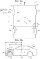
- FIG. 3A schematically illustrates the relationship between the crosswind yaw moment generated by a crosswind and a counter yaw moment generated by a difference between the driving forces applied to the rear wheels 20R, 20L.
- FIG. 3B is a side view illustrating the position of a pressure receiving region.
- the crosswind information obtaining unit 710 communicates with the outside via the wireless communication unit 70 to obtain crosswind information regarding the nearest crosswind caution region 501 located ahead in the direction of travel.
- the crosswind information contains, for example, the wind velocity Vw (see FIG. 3A ), the direction (azimuth orientation) of the wind, etc.
- the crosswind caution region 501 herein refers to a region where a crosswind tends to blow.
- Examples of the crosswind caution region 501 include a region near a tunnel exit, a region over a bridge, and a gap between noise barriers.
- the communication region is a region where the vehicle can wirelessly communicate with the outside.
- the communication region may be located near a tunnel entrance or further before the tunnel entrance.
- the crosswind information obtaining unit 710 may communicate with the expressway control traffic center to receive intelligent transport system (ITS) information and may obtain crosswind information from the ITS information.
- ITS intelligent transport system
- the ITS information contains, for example, information regarding an icy road ahead in the direction of travel, crosswind information regarding a region near a tunnel exit, and the presence of a stopped vehicle ahead in the direction of travel.
- the crosswind information obtaining unit 710 may obtain crosswind information from an anemometer or the car navigation system 8.
- Vw represents the wind velocity obtained from crosswind information
- Vy represents the component of the wind velocity Vw in a direction perpendicular to a side surface 10a of the vehicle body 10A (i.e., lateral wind velocity)
- ⁇ w represents the angle of the direction (azimuth orientation) of the wind with respect to the direction (direction of travel) of the vehicle body 10A (i.e., wind direction angle)
- Fw represents the wind load
- Fy represents the component of the wind load Fw in the direction perpendicular to the side surface 10a of the vehicle body 10A (i.e., lateral wind load)
- f L represents the driving force for the left rear wheel 20L
- f R represents the driving force for the right rear wheel 20R
- ⁇ f represents the difference in driving force (
- Mz represents the crosswind yaw moment generated by a crosswind
- Mf represents the counter yaw moment generated by the driving force difference ⁇ f
- Lg
- the predetermined region 10c (hatched region in FIG. 3B ) in the front part of the side surface 10a of the vehicle body 10A suddenly receives the wind pressure of a crosswind.
- the crosswind yaw moment estimating unit 711 estimates the crosswind yaw moment generated when the predetermined pressure receiving region 10c receives the wind pressure of the crosswind as follows.
- the crosswind yaw moment estimating unit 711 obtains the direction (direction of travel) of the vehicle from the car navigation system 8. Then, based on the obtained direction (direction of travel) of the vehicle and the direction (azimuth orientation) of the wind contained in the crosswind information, the crosswind yaw moment estimating unit 711 calculates the wind direction angle ⁇ w (see FIG. 3A ) with respect to the direction of travel of the vehicle.
- the crosswind yaw moment estimating unit 711 may obtain the wind direction angle ⁇ w from the car navigation system 8.
- the crosswind yaw moment estimating unit 711 calculates Vwsin ⁇ w from the wind direction angle ⁇ w and the wind velocity Vw contained in the crosswind information and obtains the lateral wind velocity Vy (see FIG. 3A ).
- the crosswind yaw moment estimating unit 711 calculates the lateral wind load Fy (see FIG. 3A ) using the lateral wind velocity Vy, the pressure receiving area S of the pressure receiving region 10c that is contained in the parameter information 721 stored in the storage unit 72, the air density p, etc., and obtains the distance Lw from the parameter information 721 stored in the storage unit 72.
- the crosswind yaw moment estimating unit 711 calculates Fy-Lw to calculate the crosswind yaw moment Mz (see FIG. 3A ).
- the driving force difference control unit 712 controls the driving force distribution device 35 in synchronization with the arrival of the vehicle body 10A at the crosswind caution region 501 to generate the counter yaw moment Mf against the crosswind yaw moment Mz generated on the vehicle body 10A by a crosswind.
- the driving force difference control unit 712 supplies a larger current to the second actuator 359 than to the first actuator 358 to make the driving force f R transmitted to the right rear wheel 20R larger than the driving force f L transmitted to the left rear wheel 20L.
- the driving force difference control unit 712 thus produces the driving force difference ⁇ f to generate the counter yaw moment Mf by the driving force difference ⁇ f.
- the driving force difference control unit 712 supplies a larger current to the first actuator 358 than to the second actuator 359 to make the driving force f L transmitted to the left rear wheel 20L larger than the driving force f R transmitted to the right rear wheel 20R.
- the driving force difference control unit 712 thus produces the driving force difference ⁇ f to generate the counter yaw moment Mf by the driving force difference ⁇ f.
- the driving force difference control unit 712 detects the vehicle behavior caused by the difference between the crosswind yaw moment Mz and the counter yaw moment Mf using, for example, a yaw rate sensor and corrects the driving forces f R , f L that are transmitted to the right rear wheel 20R and/or the left rear wheel 20L so as to achieve a target vehicle behavior corresponding to the steering operation (i.e., such that the vehicle behavior becomes a target vehicle behavior corresponding to the steering operation).
- the vehicle behavior may be detected based on (i.e., determined from) wheel speeds of the front wheels 10R, 10L and the rear wheels 20R, 20L.
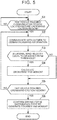
- FIG. 5 is a flowchart illustrating an example of the process that is executed by the control unit 71 of the control device 7.
- the crosswind information obtaining unit 710 determines whether the vehicle body 10A has reached a communication region located before the crosswind caution region 501 (S1). It is herein assumed that the crosswind caution region 501 is set near the exit of a tunnel 500, and the communication region is set before the tunnel 500.
- the crosswind information obtaining unit 710 determines that the vehicle body 10A has reached the communication region (S1: Yes)
- the crosswind information obtaining unit 710 communicates with the outside to obtain crosswind information (S2).
- the driving force f R that is transmitted to the right rear wheel 20R and the driving force f L that is transmitted to the left rear wheel 20L are equal to each other when the vehicle has passed the communication region and has not reached the crosswind caution region 501, for example, when the vehicle is located immediately before the exit of the tunnel 500.
- the crosswind yaw moment estimating unit 711 determines whether the lateral wind velocity Vy (see FIG. 3A ) is equal to or higher than a threshold (S3).
- the crosswind yaw moment estimating unit 711 obtains the direction (direction of travel) of the vehicle from the car navigation system 8, calculates the wind direction angle ⁇ w (see FIG. 3A ) from the direction (direction of travel) of the vehicle and the direction (azimuth orientation) of the wind contained in the crosswind information, and obtains the lateral wind velocity Vy from the wind velocity Vw contained in the crosswind information and the wind direction angle ⁇ w.
- the crosswind yaw moment estimating unit 711 calculates the lateral wind load Fy (see FIG. 3A ) and calculates the crosswind yaw moment Mz ( FIG. 3A ) (S4).
- the driving force difference control unit 712 determines whether the vehicle has reached the crosswind caution region 501 (S5). For example, the driving force difference control unit 712 can determine whether the vehicle has reached the crosswind caution region 501 by obtaining the position of the vehicle from the car navigation system 8. When the vehicle has not reached the crosswind caution region 501, the control unit 71 repeats the process of step S2 and the subsequent steps.
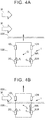
- the driving force difference control unit 712 determines that the vehicle has reached the crosswind caution region 501 as shown in FIG. 4B (S5: Yes)
- the driving force difference control unit 712 controls the driving force distribution device 35 in synchronization with the arrival of the vehicle at the crosswind caution region 501 so as to reduce the influence (i.e., impact) of a crosswind on traveling of the four-wheel drive vehicle 1.
- the driving force difference control unit 712 thus generates the counter yaw moment Mf against the crosswind yaw moment Mz generated on the vehicle body 10A by a crosswind (S6).
- the driving force difference control unit 712 supplies a larger current to the second actuator 359 than to the first actuator 358 to make the driving force f R transmitted to the right rear wheel 20R larger than the driving force f L transmitted to the left rear wheel 20L.
- the driving force difference control unit 712 thus produces the driving force difference ⁇ f to generate the counter yaw moment Mf by the driving force difference ⁇ f.
- the crosswind yaw moment is estimated before the vehicle reaches the crosswind caution region 501, and the driving force distribution device 35 is controlled so as to generate the counter yaw moment against the crosswind yaw moment.
- This configuration improves driving stability as compared to the case where the driving forces are controlled after the yaw rate resulting from a crosswind is detected when the four-wheel drive vehicle 1 is subjected to the crosswind while moving.
- FIG. 6 is a schematic configuration diagram illustrating an example of a configuration of a four-wheel drive vehicle 1A according to a second embodiment of the invention.
- the same components as those described in the first embodiment are denoted with the same reference characters as those used in FIG. 1 , and repetitive description will be omitted.
- the driving force generated by the engine 11 is distributed to the front wheels 10R, 10L and the rear wheels 20R, 20L.
- the front wheels 10R, 10L are driven by the driving force generated by the engine 11 as in the first embodiment, and the rear wheels 20R, 20L are driven by an electric motor 21 of an auxiliary drive device 2.
- the rotational speed of the output from the engine 11 is changed by the transmission 12 and then the driving force of the engine 11 is differentially distributed to the right and left drive shafts 14R, 14L through the front differential 13.
- the rotational speed of the output from the electric motor 21 of the auxiliary drive device 2 is reduced by a reduction gear mechanism 23 and then the driving force of the electric motor 21 is transmitted to the driving force distribution device 35 having a configuration similar to that of the first embodiment.
- the reduction gear mechanism 23 includes a pinion gear 231 fixed to a shaft of the electric motor 21, a large-diameter gear portion 232 meshing with the pinion gear 231, and a small-diameter gear portion 233 meshing with the ring gear 351 of the driving force distribution device 35.
- the large-diameter gear portion 232 and the small-diameter gear portion 233 are coupled so as not to be rotatable relative to each other.
- the crosswind yaw moment is estimated before the vehicle reaches the crosswind caution region 501, and the driving force distribution device 35 is controlled so as to generate the counter yaw moment against the crosswind yaw moment.
- This configuration improves driving stability as compared to the case where the driving forces are controlled after the yaw rate resulting from a crosswind is detected when the four-wheel drive vehicle 1A is subjected to the crosswind.
- FIG. 7 is a schematic configuration diagram illustrating an example of a configuration of a four-wheel drive vehicle 1B according to a third embodiment of the invention.
- the same components as those described in the first embodiment are denoted with the same reference characters as those used in FIG. 1 , and repetitive description will be omitted.
- the driving force generated by the engine 11 is distributed to the front wheels 10R, 10L and the rear wheels 20R, 20L.
- the front wheels 10R, 10L are driven by the driving force generated by the engine 11 as in the first embodiment
- the left rear wheel 20L is driven by an electric motor 21A of a first auxiliary drive device 2A
- the right rear wheel 20R is driven by an electric motor 21B of a second auxiliary drive device 2B.
- the rotational speed of the output from the electric motor 21A of the first auxiliary drive device 2A is reduced by a reduction gear mechanism 23A, and then the driving force of the electric motor 21A is transmitted to the rear-wheel drive shaft 24L via a gear 36 provided on the end of the rear-wheel drive shaft 24L.
- the rotational speed of the output from the electric motor 21B of the second auxiliary drive device 2B is reduced by a reduction gear mechanism 23B, and then the driving force of the electric motor 21B is transmitted to the rear-wheel drive shaft 24R via a gear 37 provided on the end of the rear-wheel drive shaft 24R.
- the reduction gear mechanism 23A of the first auxiliary drive device 2A includes a pinion gear 231a fixed to a shaft of the electric motor 21A, a large-diameter gear portion 232a meshing with the pinion gear 231a, and a small-diameter gear portion 233a meshing with the gear 36.
- the large-diameter gear portion 232a and the small-diameter gear portion 233a are coupled so as not to be rotatable relative to each other.
- the reduction gear mechanism 23B of the second auxiliary drive device 2B includes a pinion gear 231b fixed to a shaft of the electric motor 21B, a large-diameter gear portion 232b meshing with the pinion gear 231b, and a small-diameter gear portion 233b meshing with the gear 37.
- the large-diameter gear portion 232b and the small-diameter gear portion 233b are coupled so as not to be rotatable relative to each other.
- the first auxiliary drive device 2A, the second auxiliary drive device 2B, and the gears 36, 37 form the driving force distribution device 35.
- the driving force difference control unit 712 of the present embodiment controls the driving force distribution device 35 when the vehicle reaches the crosswind caution region 501 to generate the counter yaw moment Mf against the crosswind yaw moment Mz generated on the vehicle body 10A by a crosswind.
- the driving force difference control unit 712 supplies a larger current to the electric motor 21B of the second auxiliary drive device 2B than to the electric motor 21A of the first auxiliary drive device 2A to make the driving force f R transmitted to the right rear wheel 20R larger than the driving force f L transmitted to the left rear wheel 20L.
- the driving force difference control unit 712 thus produces the driving force difference ⁇ f to generate the counter yaw moment Mf by the driving force difference ⁇ f.
- the driving force difference control unit 712 supplies a larger current to the electric motor 21A of the first auxiliary drive device 2A than to the electric motor 21B of the second auxiliary drive device 2B to make the driving force f L transmitted to the left rear wheel 20L larger than the driving force f R transmitted to the right rear wheel 20R.
- the driving force difference control unit 712 thus produces the driving force difference ⁇ f to generate the counter yaw moment Mf by the driving force difference ⁇ f.
- the driving force difference control unit 712 detects the vehicle behavior caused by the difference between the crosswind yaw moment Mz and the counter yaw moment Mf using, for example, a yaw rate sensor and corrects the driving forces f R , f L transmitted to the right rear wheel 20R and/or the left rear wheel 20L so as to achieve a target vehicle behavior corresponding to the steering operation (i.e., the vehicle behavior becomes a target vehicle behavior corresponding to the steering operation).
- the vehicle behavior may be detected based on (i.e., determined from) wheel speeds of the front wheels 10R, 10L and the rear wheels 20R, 20L.
- the crosswind yaw moment is estimated before the vehicle reaches the crosswind caution region 501, and the first auxiliary drive device 2A and the second auxiliary drive device 2B are controlled so as to generate the counter yaw moment against the crosswind yaw moment.
- This configuration improves driving stability as compared to the case where the driving forces are controlled after the yaw rate resulting from a crosswind is detected when the four-wheel drive vehicle 1B is subjected to the crosswind while moving.
- the crosswind information obtaining unit 710 may obtain the speed of the vehicle, information regarding the current position of the vehicle, and information regarding the measurement position at which a crosswind is measured
- the driving force difference control unit 712 may estimate the time at which the vehicle reaches the measurement position and control the driving forces so as to reduce the influence of the crosswind at the estimated time.
- the counter yaw moment is generated by the difference between the driving forces transmitted to the rear wheels 20R, 20L.
- the counter yaw moment may be generated by the difference between the driving forces transmitted to the front wheels 10R, 10L.
- a driving force distribution control device is configured to control driving forces for right and left wheels of a vehicle.
- the driving force distribution control device includes an electronic control unit (71) configured to obtain crosswind information regarding a crosswind to which the vehicle is to be subjected in a predetermined region located ahead in a direction of travel of the vehicle, and to control, in synchronization with arrival of the vehicle at the predetermined region, the driving forces for the right and left wheels based on the crosswind information so as to reduce an influence of the crosswind on traveling of the vehicle.
Landscapes
- Engineering & Computer Science (AREA)
- Transportation (AREA)
- Mechanical Engineering (AREA)
- Automation & Control Theory (AREA)
- Chemical & Material Sciences (AREA)
- Combustion & Propulsion (AREA)
- Physics & Mathematics (AREA)
- Mathematical Physics (AREA)
- Human Computer Interaction (AREA)
- Control Of Driving Devices And Active Controlling Of Vehicle (AREA)
- Arrangement And Mounting Of Devices That Control Transmission Of Motive Force (AREA)
- Arrangement And Driving Of Transmission Devices (AREA)
Abstract
Description
- The invention relates to a driving force distribution control device that is applied to a four-wheel drive vehicle, and that is configured to control driving forces for front and rear wheels.
- There has been proposed a driving force distribution control device which performs right and left wheel driving force distribution control (what is called torque vectoring control). Under the right and left wheel driving force distribution control, the driving forces for the right and left wheels are made different from each other so that a vehicle has a turning behavior corresponding to the driving state (see, for example, Japanese Unexamined Patent Application Publication No.
2012-17053 JP 2012-17053 A - The driving force distribution control device described in
JP 2012-17053 A - However, the driving force distribution control device in the related art controls the driving forces only after it detects a change in actual yaw rate in a case where a disturbance occurs. Accordingly, the vehicle's behavior becomes unstable at the time when, for example, a crosswind disturbance occurs, which may make the driver feel uneasy.
- The invention provides a driving force distribution control device capable of further improving driving stability as compared to the case where the driving forces for right and left wheels are controlled after a change in yaw rate due to a crosswind is detected.
- An aspect of the invention relates to a driving force distribution control device configured to control driving forces for right and left wheels of a vehicle. The driving force distribution control device includes an electronic control unit configured to obtain crosswind information regarding a crosswind to which the vehicle is to be subjected in a predetermined region located ahead in a direction of travel of the vehicle, and to control, in synchronization with arrival of the vehicle at the predetermined region, the driving forces for the right and left wheels based on the crosswind information so as to reduce an influence of the crosswind on traveling of the vehicle.
- The driving force distribution control device according to the above aspect of the invention improves driving stability as compared to the case where the driving forces are controlled after a change in yaw rate due to a crosswind is detected.
- Features, advantages, and technical and industrial significance of exemplary embodiments of the invention will be described below with reference to the accompanying drawings, in which like numerals denote like elements, and wherein:
-
FIG. 1 is a schematic configuration diagram illustrating an example of a configuration of a four-wheel drive vehicle including a driving force distribution control device according to a first embodiment of the invention; -
FIG. 2 is a block diagram illustrating an example of a functional configuration of a control device; -
FIG. 3A schematically illustrates the relationship between the crosswind yaw moment generated by a crosswind and the counter yaw moment generated by the difference between driving forces to rear wheels, andFIG. 3B is a side view illustrating the position of a pressure receiving region; -
FIGS. 4A and 4B schematically illustrate how the driving forces acting on the rear wheels change between a position before a tunnel exit and a position near the tunnel exit; -
FIG. 5 is a flowchart illustrating an example of a process that is executed by a control unit of a control device; -
FIG. 6 is a schematic configuration diagram illustrating an example of a configuration of a four-wheel drive vehicle according to a second embodiment; and -
FIG. 7 is a schematic configuration diagram illustrating an example of a configuration of a four-wheel drive vehicle according to a third embodiment. - A first embodiment of the invention will be described with reference to
FIGS. 1 to 5 . Embodiments described below are given as specific examples for carrying out the invention. However, the technical scope of the invention is not limited to the embodiments. -
FIG. 1 is a schematic configuration diagram illustrating an example of a configuration of a four-wheel drive vehicle including a driving force distribution control device according to the first embodiment of the invention.FIG. 2 is a block diagram illustrating an example of a functional configuration of a control device. - As shown in
FIG. 1 , a four-wheel drive vehicle 1 includes avehicle body 10A, anengine 11 that is a driving source, atransmission 12, right and leftfront wheels rear wheels force transmission system 3, asteering wheel 50, acontrol device 7, and acar navigation system 8. The drivingforce transmission system 3 transmits an output of thetransmission 12 to thefront wheels rear wheels steering wheel 50 steers thefront wheels control device 7 controls a drivingforce distribution device 35 of the drivingforce transmission system 3, etc. Thecar navigation system 8 provides driving directions. The four-wheel drive vehicle 1 is an example of a vehicle. Thecontrol device 7 is an example of a driving force distribution control device. The four-wheel drive vehicle 1 including thecontrol device 7 described below is hereinafter sometimes referred to as the vehicle. - The driving
force transmission system 3 includes afront differential 13, front-wheel drive shafts propeller shaft 34, the drivingforce distribution device 35, and rear-wheel drive shafts - The
front differential 13 includes adifferential case 131, apinion shaft 132, a pair ofpinion gears 133, and a pair ofside gears pinion shaft 132 is supported at both ends by thedifferential case 131. Thepinion gears 133 are supported on thepinion shaft 132. The pair ofside gears pinion gears 133 such that the axes of theside gears pinion gears 133. The right andleft drive shafts side gears drive shafts side gears - A
ring gear 135 is fixed to thedifferential case 131. Thepropeller shaft 34 has apinion gear 341 on its front end in the longitudinal direction (i.e., the front-rear direction) of the vehicle, and thering gear 135 meshes with thepinion gear 341. - The driving
force distribution device 35 distributes the driving force received from thepropeller shaft 34 to the right and leftrear wheels wheel drive shafts force distribution device 35 includes apinion gear 350, aring gear 351, first andsecond clutch housings second multiplate clutches second output shafts second actuators pinion gear 350 rotates with thepropeller shaft 34. Thering gear 351 meshes with thepinion gear 350. The first andsecond clutch housings ring gear 351. The first andsecond multiplate clutches second clutch housings second output shafts second multiplate clutches second actuators second multiplate clutches - The
ring gear 351 and the first andsecond clutch housings first output shaft 356 and thedrive shaft 24L that rotates with thefirst output shaft 356 to the leftrear wheel 20L. The driving force is transmitted from thesecond output shaft 357 and thedrive shaft 24R that rotates with thesecond output shaft 357 to the rightrear wheel 20R. - The first
multi-plate clutch 354 includes a plurality ofouter clutch plates 354a that rotate with thefirst clutch housing 352 and a plurality ofinner clutch plates 354b that rotate with thefirst output shaft 356. When receiving a pressing force from thefirst actuator 358, theouter clutch plates 354a and theinner clutch plates 354b frictionally contact each other to transmit the driving force. - Similarly, the second
multi-plate clutch 355 includes a plurality ofouter clutch plates 355a that rotate with thesecond clutch housing 353 and a plurality ofinner clutch plates 355b that rotate with thesecond output shaft 357. When receiving a pressing force from thesecond actuator 359, theouter clutch plates 355a and theinner clutch plates 355b frictionally contact each other to transmit the driving force. - Each of the first and
second actuators second actuators multiplate clutches control device 7. Thecontrol device 7 is capable of controlling the driving forces that are distributed to the right and leftrear wheels second actuators - The driving
force transmission system 3 configured as described above constantly transmits the output of thetransmission 12 to the right and leftfront wheels wheel drive shafts force transmission system 3 transmits the driving force corresponding to the current supplied to thefirst actuator 358 to the leftrear wheel 20L and transmits the driving force corresponding to the current supplied to thesecond actuator 359 to the rightrear wheel 20R. With this configuration, thecontrol device 7 is capable of controlling the driving force distribution ratio between thefront wheels rear wheels rear wheel 20R and the leftrear wheel 20L. - As shown in
FIG. 2 , thecontrol device 7 includes, for example, awireless communication unit 70, acontrol unit 71, astorage unit 72, and acurrent output circuit 73. Thewireless communication unit 70 wirelessly communicates with the outside such as an expressway traffic control center. Thecurrent output circuit 73 supplies a current to the first andsecond actuators control device 7 is configured to receive various detection values including detection values ofrotational speed sensors 101 to 104 that detect the rotational speeds of thewheels - The
control unit 71 includes a central processing unit (CPU) and its peripheral circuits. The CPU of thecontrol unit 71 operates according to aprogram 720 stored in thestorage unit 72 to function as a crosswindinformation obtaining unit 710, a crosswind yawmoment estimating unit 711, a driving forcedifference control unit 712, etc. In other words, thecontrol unit 71 is an electronic control unit. - The
storage unit 72 includes memory devices such as a read only memory (ROM) and a random access memory (RAM). Thestorage unit 72 stores various kinds of information such as theprogram 720 andparameter information 721. Theparameter information 721 contains, for example, the pressure receiving area S for a crosswind in the four-wheel drive vehicle 1 and the distances Lw, Lg (seeFIGS. 3A and 3B ) that will be described later. Such information is used to calculate a crosswind yaw moment Mz. - Next, the control process of each of
units 710 to 712 of thecontrol unit 71 will be described with reference toFIGS. 3A, 3B andFIGS. 4A, 4B .FIG. 3A schematically illustrates the relationship between the crosswind yaw moment generated by a crosswind and a counter yaw moment generated by a difference between the driving forces applied to therear wheels FIG. 3B is a side view illustrating the position of a pressure receiving region. - When the vehicle moving on a road reaches a communication region located before (behind in the direction of travel) a predetermined region (hereinafter sometimes referred to as the "crosswind caution region") 501 (see
FIGS. 4A and 4B ), the crosswindinformation obtaining unit 710 communicates with the outside via thewireless communication unit 70 to obtain crosswind information regarding the nearestcrosswind caution region 501 located ahead in the direction of travel. The crosswind information contains, for example, the wind velocity Vw (seeFIG. 3A ), the direction (azimuth orientation) of the wind, etc. Thecrosswind caution region 501 herein refers to a region where a crosswind tends to blow. Examples of thecrosswind caution region 501 include a region near a tunnel exit, a region over a bridge, and a gap between noise barriers. The communication region is a region where the vehicle can wirelessly communicate with the outside. For example, the communication region may be located near a tunnel entrance or further before the tunnel entrance. - An example of the outside with which the vehicle communicates is the expressway traffic control center. The crosswind
information obtaining unit 710 may communicate with the expressway control traffic center to receive intelligent transport system (ITS) information and may obtain crosswind information from the ITS information. The ITS information contains, for example, information regarding an icy road ahead in the direction of travel, crosswind information regarding a region near a tunnel exit, and the presence of a stopped vehicle ahead in the direction of travel. The crosswindinformation obtaining unit 710 may obtain crosswind information from an anemometer or thecar navigation system 8. - In
FIGS. 3A and 3B , Vw represents the wind velocity obtained from crosswind information, Vy represents the component of the wind velocity Vw in a direction perpendicular to a side surface 10a of the vehicle body 10A (i.e., lateral wind velocity), θw represents the angle of the direction (azimuth orientation) of the wind with respect to the direction (direction of travel) of the vehicle body 10A (i.e., wind direction angle), Fw represents the wind load, Fy represents the component of the wind load Fw in the direction perpendicular to the side surface 10a of the vehicle body 10A (i.e., lateral wind load), fL represents the driving force for the left rear wheel 20L, fR represents the driving force for the right rear wheel 20R, Δf represents the difference in driving force (|fL - fR|), Mz represents the crosswind yaw moment generated by a crosswind, Mf represents the counter yaw moment generated by the driving force difference Δf, Lg represents the distance from a front surface 10b of the vehicle body 10A to the center of gravity G of the vehicle as the vehicle body 10A is viewed in the lateral direction of the vehicle, and Lw represents the distance from a pressure receiving center 10d, which is the geometric center of the area (i.e., the pressure receiving area) of a pressure receiving region 10c, to the center of gravity G of the vehicle as the vehicle body 10A is viewed in the lateral direction of the vehicle. - When a part of the
vehicle body 10A enters thecrosswind caution region 501 while the vehicle is moving forward, the predetermined region (hereinafter sometimes referred to as the "pressure receiving region") 10c (hatched region inFIG. 3B ) in the front part of theside surface 10a of thevehicle body 10A suddenly receives the wind pressure of a crosswind. The crosswind yawmoment estimating unit 711 estimates the crosswind yaw moment generated when the predeterminedpressure receiving region 10c receives the wind pressure of the crosswind as follows. - For example, the crosswind yaw
moment estimating unit 711 obtains the direction (direction of travel) of the vehicle from thecar navigation system 8. Then, based on the obtained direction (direction of travel) of the vehicle and the direction (azimuth orientation) of the wind contained in the crosswind information, the crosswind yawmoment estimating unit 711 calculates the wind direction angle θw (seeFIG. 3A ) with respect to the direction of travel of the vehicle. The crosswind yawmoment estimating unit 711 may obtain the wind direction angle θw from thecar navigation system 8. - The crosswind yaw
moment estimating unit 711 calculates Vwsinθw from the wind direction angle θw and the wind velocity Vw contained in the crosswind information and obtains the lateral wind velocity Vy (seeFIG. 3A ). The crosswind yawmoment estimating unit 711 calculates the lateral wind load Fy (seeFIG. 3A ) using the lateral wind velocity Vy, the pressure receiving area S of thepressure receiving region 10c that is contained in theparameter information 721 stored in thestorage unit 72, the air density p, etc., and obtains the distance Lw from theparameter information 721 stored in thestorage unit 72. The crosswind yawmoment estimating unit 711 calculates Fy-Lw to calculate the crosswind yaw moment Mz (seeFIG. 3A ). - The driving force
difference control unit 712 controls the drivingforce distribution device 35 in synchronization with the arrival of thevehicle body 10A at thecrosswind caution region 501 to generate the counter yaw moment Mf against the crosswind yaw moment Mz generated on thevehicle body 10A by a crosswind. - When it is predicted that a clockwise crosswind yaw moment Mz will be generated, the driving force
difference control unit 712 supplies a larger current to thesecond actuator 359 than to thefirst actuator 358 to make the driving force fR transmitted to the rightrear wheel 20R larger than the driving force fL transmitted to the leftrear wheel 20L. The driving forcedifference control unit 712 thus produces the driving force difference Δf to generate the counter yaw moment Mf by the driving force difference Δf. When it is predicted that a counterclockwise crosswind yaw moment Mz will be generated, the driving forcedifference control unit 712 supplies a larger current to thefirst actuator 358 than to thesecond actuator 359 to make the driving force fL transmitted to the leftrear wheel 20L larger than the driving force fR transmitted to the rightrear wheel 20R. The driving forcedifference control unit 712 thus produces the driving force difference Δf to generate the counter yaw moment Mf by the driving force difference Δf. - After the counter yaw moment Mf is generated, the driving force
difference control unit 712 detects the vehicle behavior caused by the difference between the crosswind yaw moment Mz and the counter yaw moment Mf using, for example, a yaw rate sensor and corrects the driving forces fR, fL that are transmitted to the rightrear wheel 20R and/or the leftrear wheel 20L so as to achieve a target vehicle behavior corresponding to the steering operation (i.e., such that the vehicle behavior becomes a target vehicle behavior corresponding to the steering operation). The vehicle behavior may be detected based on (i.e., determined from) wheel speeds of thefront wheels rear wheels - Operation of the present embodiment will be described. An example of a process that is executed by the
control unit 71 of thecontrol device 7 will be described with reference toFIG. 5. FIG. 5 is a flowchart illustrating an example of the process that is executed by thecontrol unit 71 of thecontrol device 7. - The crosswind
information obtaining unit 710 determines whether thevehicle body 10A has reached a communication region located before the crosswind caution region 501 (S1). It is herein assumed that thecrosswind caution region 501 is set near the exit of atunnel 500, and the communication region is set before thetunnel 500. - When the crosswind
information obtaining unit 710 determines that thevehicle body 10A has reached the communication region (S1: Yes), the crosswindinformation obtaining unit 710 communicates with the outside to obtain crosswind information (S2). - As shown in
FIG. 4A , the driving force fR that is transmitted to the rightrear wheel 20R and the driving force fL that is transmitted to the leftrear wheel 20L are equal to each other when the vehicle has passed the communication region and has not reached thecrosswind caution region 501, for example, when the vehicle is located immediately before the exit of thetunnel 500. - The crosswind yaw
moment estimating unit 711 determines whether the lateral wind velocity Vy (seeFIG. 3A ) is equal to or higher than a threshold (S3). The crosswind yawmoment estimating unit 711 obtains the direction (direction of travel) of the vehicle from thecar navigation system 8, calculates the wind direction angle θw (seeFIG. 3A ) from the direction (direction of travel) of the vehicle and the direction (azimuth orientation) of the wind contained in the crosswind information, and obtains the lateral wind velocity Vy from the wind velocity Vw contained in the crosswind information and the wind direction angle θw. - Next, when the lateral wind velocity Vy is equal to or higher than the threshold (S3: Yes), the crosswind yaw
moment estimating unit 711 calculates the lateral wind load Fy (seeFIG. 3A ) and calculates the crosswind yaw moment Mz (FIG. 3A ) (S4). - The driving force
difference control unit 712 determines whether the vehicle has reached the crosswind caution region 501 (S5). For example, the driving forcedifference control unit 712 can determine whether the vehicle has reached thecrosswind caution region 501 by obtaining the position of the vehicle from thecar navigation system 8. When the vehicle has not reached thecrosswind caution region 501, thecontrol unit 71 repeats the process of step S2 and the subsequent steps. - When the driving force
difference control unit 712 determines that the vehicle has reached thecrosswind caution region 501 as shown inFIG. 4B (S5: Yes), the driving forcedifference control unit 712 controls the drivingforce distribution device 35 in synchronization with the arrival of the vehicle at thecrosswind caution region 501 so as to reduce the influence (i.e., impact) of a crosswind on traveling of the four-wheel drive vehicle 1. The driving forcedifference control unit 712 thus generates the counter yaw moment Mf against the crosswind yaw moment Mz generated on thevehicle body 10A by a crosswind (S6). - In the case shown in
FIG. 4A , the driving forcedifference control unit 712 supplies a larger current to thesecond actuator 359 than to thefirst actuator 358 to make the driving force fR transmitted to the rightrear wheel 20R larger than the driving force fL transmitted to the leftrear wheel 20L. The driving forcedifference control unit 712 thus produces the driving force difference Δf to generate the counter yaw moment Mf by the driving force difference Δf. - Functions and effects of the first embodiment will be described. According to the first embodiment described above, the crosswind yaw moment is estimated before the vehicle reaches the
crosswind caution region 501, and the drivingforce distribution device 35 is controlled so as to generate the counter yaw moment against the crosswind yaw moment. This configuration improves driving stability as compared to the case where the driving forces are controlled after the yaw rate resulting from a crosswind is detected when the four-wheel drive vehicle 1 is subjected to the crosswind while moving. -
FIG. 6 is a schematic configuration diagram illustrating an example of a configuration of a four-wheel drive vehicle 1A according to a second embodiment of the invention. InFIG. 6 , the same components as those described in the first embodiment are denoted with the same reference characters as those used inFIG. 1 , and repetitive description will be omitted. - In the first embodiment, the driving force generated by the
engine 11 is distributed to thefront wheels rear wheels front wheels engine 11 as in the first embodiment, and therear wheels electric motor 21 of anauxiliary drive device 2. - As in the first embodiment, the rotational speed of the output from the
engine 11 is changed by thetransmission 12 and then the driving force of theengine 11 is differentially distributed to the right and leftdrive shafts - The rotational speed of the output from the
electric motor 21 of theauxiliary drive device 2 is reduced by a reduction gear mechanism 23 and then the driving force of theelectric motor 21 is transmitted to the drivingforce distribution device 35 having a configuration similar to that of the first embodiment. - The reduction gear mechanism 23 includes a
pinion gear 231 fixed to a shaft of theelectric motor 21, a large-diameter gear portion 232 meshing with thepinion gear 231, and a small-diameter gear portion 233 meshing with thering gear 351 of the drivingforce distribution device 35. The large-diameter gear portion 232 and the small-diameter gear portion 233 are coupled so as not to be rotatable relative to each other. - Functions and effects of the second embodiment will be described. According to the second embodiment described above, as in the first embodiment, the crosswind yaw moment is estimated before the vehicle reaches the
crosswind caution region 501, and the drivingforce distribution device 35 is controlled so as to generate the counter yaw moment against the crosswind yaw moment. This configuration improves driving stability as compared to the case where the driving forces are controlled after the yaw rate resulting from a crosswind is detected when the four-wheel drive vehicle 1A is subjected to the crosswind. -
FIG. 7 is a schematic configuration diagram illustrating an example of a configuration of a four-wheel drive vehicle 1B according to a third embodiment of the invention. InFIG. 7 , the same components as those described in the first embodiment are denoted with the same reference characters as those used inFIG. 1 , and repetitive description will be omitted. - In the first embodiment, the driving force generated by the
engine 11 is distributed to thefront wheels rear wheels front wheels engine 11 as in the first embodiment, the leftrear wheel 20L is driven by anelectric motor 21A of a firstauxiliary drive device 2A, and the rightrear wheel 20R is driven by anelectric motor 21B of a secondauxiliary drive device 2B. - The rotational speed of the output from the
electric motor 21A of the firstauxiliary drive device 2A is reduced by areduction gear mechanism 23A, and then the driving force of theelectric motor 21A is transmitted to the rear-wheel drive shaft 24L via agear 36 provided on the end of the rear-wheel drive shaft 24L. The rotational speed of the output from theelectric motor 21B of the secondauxiliary drive device 2B is reduced by a reduction gear mechanism 23B, and then the driving force of theelectric motor 21B is transmitted to the rear-wheel drive shaft 24R via agear 37 provided on the end of the rear-wheel drive shaft 24R. - The
reduction gear mechanism 23A of the firstauxiliary drive device 2A includes apinion gear 231a fixed to a shaft of theelectric motor 21A, a large-diameter gear portion 232a meshing with thepinion gear 231a, and a small-diameter gear portion 233a meshing with thegear 36. The large-diameter gear portion 232a and the small-diameter gear portion 233a are coupled so as not to be rotatable relative to each other. The reduction gear mechanism 23B of the secondauxiliary drive device 2B includes apinion gear 231b fixed to a shaft of theelectric motor 21B, a large-diameter gear portion 232b meshing with thepinion gear 231b, and a small-diameter gear portion 233b meshing with thegear 37. The large-diameter gear portion 232b and the small-diameter gear portion 233b are coupled so as not to be rotatable relative to each other. In the present embodiment, the firstauxiliary drive device 2A, the secondauxiliary drive device 2B, and thegears force distribution device 35. - As in the first embodiment, the driving force
difference control unit 712 of the present embodiment controls the drivingforce distribution device 35 when the vehicle reaches thecrosswind caution region 501 to generate the counter yaw moment Mf against the crosswind yaw moment Mz generated on thevehicle body 10A by a crosswind. - When it is predicted that a clockwise crosswind yaw moment Mz will be generated, the driving force
difference control unit 712 supplies a larger current to theelectric motor 21B of the secondauxiliary drive device 2B than to theelectric motor 21A of the firstauxiliary drive device 2A to make the driving force fR transmitted to the rightrear wheel 20R larger than the driving force fL transmitted to the leftrear wheel 20L. The driving forcedifference control unit 712 thus produces the driving force difference Δf to generate the counter yaw moment Mf by the driving force difference Δf. When it is predicted that a counterclockwise crosswind yaw moment Mz will be generated, the driving forcedifference control unit 712 supplies a larger current to theelectric motor 21A of the firstauxiliary drive device 2A than to theelectric motor 21B of the secondauxiliary drive device 2B to make the driving force fL transmitted to the leftrear wheel 20L larger than the driving force fR transmitted to the rightrear wheel 20R. The driving forcedifference control unit 712 thus produces the driving force difference Δf to generate the counter yaw moment Mf by the driving force difference Δf. - After the counter yaw moment Mf is generated, the driving force
difference control unit 712 detects the vehicle behavior caused by the difference between the crosswind yaw moment Mz and the counter yaw moment Mf using, for example, a yaw rate sensor and corrects the driving forces fR, fL transmitted to the rightrear wheel 20R and/or the leftrear wheel 20L so as to achieve a target vehicle behavior corresponding to the steering operation (i.e., the vehicle behavior becomes a target vehicle behavior corresponding to the steering operation). The vehicle behavior may be detected based on (i.e., determined from) wheel speeds of thefront wheels rear wheels - Functions and effects of the third embodiment will be described. According to the third embodiment described above, the crosswind yaw moment is estimated before the vehicle reaches the
crosswind caution region 501, and the firstauxiliary drive device 2A and the secondauxiliary drive device 2B are controlled so as to generate the counter yaw moment against the crosswind yaw moment. This configuration improves driving stability as compared to the case where the driving forces are controlled after the yaw rate resulting from a crosswind is detected when the four-wheel drive vehicle 1B is subjected to the crosswind while moving. - The invention is described based on the embodiments. However, these embodiments are not intended to limit the scope of the invention.
- The invention may be modified as appropriate without departing from the scope of the invention. For example, the crosswind
information obtaining unit 710 may obtain the speed of the vehicle, information regarding the current position of the vehicle, and information regarding the measurement position at which a crosswind is measured, and the driving forcedifference control unit 712 may estimate the time at which the vehicle reaches the measurement position and control the driving forces so as to reduce the influence of the crosswind at the estimated time. - In each of the above embodiments, the counter yaw moment is generated by the difference between the driving forces transmitted to the
rear wheels front wheels - A driving force distribution control device is configured to control driving forces for right and left wheels of a vehicle. The driving force distribution control device includes an electronic control unit (71) configured to obtain crosswind information regarding a crosswind to which the vehicle is to be subjected in a predetermined region located ahead in a direction of travel of the vehicle, and to control, in synchronization with arrival of the vehicle at the predetermined region, the driving forces for the right and left wheels based on the crosswind information so as to reduce an influence of the crosswind on traveling of the vehicle.
Claims (5)
- A driving force distribution control device configured to control driving forces for right and left wheels of a vehicle, the driving force distribution control device being characterized by comprising
an electronic control unit (71) configured to obtain crosswind information regarding a crosswind to which the vehicle is to be subjected in a predetermined region located ahead in a direction of travel of the vehicle, and to control, in synchronization with arrival of the vehicle at the predetermined region, the driving forces for the right and left wheels based on the crosswind information so as to reduce an influence of the crosswind on traveling of the vehicle. - The driving force distribution control device according to claim 1, wherein:the crosswind information contains a wind velocity and a wind direction;the electronic control unit (71) is configured to estimate, based on the crosswind information, a crosswind yaw moment to be generated on a vehicle body of the vehicle by the crosswind; andthe electronic control unit (71) is configured to control driving of the right and left wheels in synchronization with the arrival of the vehicle at the predetermined region to generate a counter yaw moment against the crosswind yaw moment.
- The driving force distribution control device according to claim 2, wherein the electronic control unit (71) is configured to estimate the crosswind yaw moment based on a pressure receiving area of a pressure receiving region to be subjected to the crosswind and a distance from a pressure receiving center of the pressure receiving region to a center of gravity of the vehicle, the pressure receiving region being a region of a side surface of the vehicle body that is located ahead of the center of gravity of the vehicle, and the pressure receiving area of the pressure receiving region and the distance being set for each vehicle model.
- The driving force distribution control device according to any one of claims 1 to 3, wherein:the electronic control unit (71) is configured to obtain a speed of the vehicle, information regarding a current position of the vehicle, and information on a measurement position at which the crosswind is measured; andthe electronic control unit (71) is configured to estimate a time at which the vehicle reaches the measurement position, and to control the driving forces for the right and left wheels at the estimated time.
- The driving force distribution control device according to any one of claims 1 to 4, wherein:the electronic control unit (71) is configured to determine a vehicle behavior from a yaw rate or wheel speeds; andthe electronic control unit (71) is configured to control the driving forces for the right and left wheels to generate a counter yaw moment, and then control the driving forces for the right and left wheels such that the vehicle behavior becomes a vehicle behavior corresponding to a steering operation.
Applications Claiming Priority (1)
| Application Number | Priority Date | Filing Date | Title |
|---|---|---|---|
| JP2018215035A JP2020082767A (en) | 2018-11-15 | 2018-11-15 | Drive power distribution control device |
Publications (1)
| Publication Number | Publication Date |
|---|---|
| EP3659888A1 true EP3659888A1 (en) | 2020-06-03 |
Family
ID=68609876
Family Applications (1)
| Application Number | Title | Priority Date | Filing Date |
|---|---|---|---|
| EP19208787.2A Withdrawn EP3659888A1 (en) | 2018-11-15 | 2019-11-13 | Driving force distribution control device |
Country Status (4)
| Country | Link |
|---|---|
| US (1) | US20200156623A1 (en) |
| EP (1) | EP3659888A1 (en) |
| JP (1) | JP2020082767A (en) |
| CN (1) | CN111216549A (en) |
Cited By (1)
| Publication number | Priority date | Publication date | Assignee | Title |
|---|---|---|---|---|
| EP3922524A1 (en) * | 2020-06-08 | 2021-12-15 | KNORR-BREMSE Systeme für Nutzfahrzeuge GmbH | A system for supporting wind detection and compensation in a vehicle |
Families Citing this family (9)
| Publication number | Priority date | Publication date | Assignee | Title |
|---|---|---|---|---|
| US11400940B2 (en) * | 2020-09-28 | 2022-08-02 | Ford Global Technologies, Llc | Crosswind risk determination |
| JP7138151B2 (en) * | 2020-11-24 | 2022-09-15 | 本田技研工業株式会社 | VEHICLE CONTROL DEVICE, VEHICLE CONTROL METHOD, AND PROGRAM |
| US12078995B1 (en) * | 2021-04-26 | 2024-09-03 | Zoox, Inc. | Vehicle control based on wind compensation |
| US12246751B1 (en) | 2021-04-26 | 2025-03-11 | Zoox, Inc. | Trajectory modification based on wind compensation |
| DE102021204245A1 (en) * | 2021-04-28 | 2022-11-03 | Dana Graziano S.R.L. | hybrid drive unit |
| US11760348B2 (en) * | 2021-09-27 | 2023-09-19 | Ford Global Technologies, Llc | Vehicle boundary control |
| DE102022203348A1 (en) * | 2022-04-05 | 2023-10-05 | Hyundai Motor Company | Method and system for active and selective preventive lateral force and noise control in a motor vehicle that is being overtaken by another motor vehicle |
| US11940022B2 (en) | 2022-07-15 | 2024-03-26 | Rivian Ip Holdings, Llc | Integrated disconnect for drive unit |
| DE102023118333A1 (en) * | 2023-07-15 | 2025-01-16 | Rivian Ip Holdings, Llc | INTEGRATED SEPARATOR FOR A DRIVE UNIT |
Citations (3)
| Publication number | Priority date | Publication date | Assignee | Title |
|---|---|---|---|---|
| JP2012017053A (en) | 2010-07-09 | 2012-01-26 | Nissan Motor Co Ltd | Control device for distribution of right and left wheels driving force for vehicle |
| CN105774781A (en) * | 2016-04-13 | 2016-07-20 | 谭希韬 | Global and local automotive crosswind stability control auxiliary system |
| US20170361834A1 (en) * | 2016-06-21 | 2017-12-21 | Ford Global Technologies, Llc | System for mitigating vehicle sway |
-
2018
- 2018-11-15 JP JP2018215035A patent/JP2020082767A/en active Pending
-
2019
- 2019-11-07 CN CN201911081729.5A patent/CN111216549A/en active Pending
- 2019-11-11 US US16/679,481 patent/US20200156623A1/en not_active Abandoned
- 2019-11-13 EP EP19208787.2A patent/EP3659888A1/en not_active Withdrawn
Patent Citations (3)
| Publication number | Priority date | Publication date | Assignee | Title |
|---|---|---|---|---|
| JP2012017053A (en) | 2010-07-09 | 2012-01-26 | Nissan Motor Co Ltd | Control device for distribution of right and left wheels driving force for vehicle |
| CN105774781A (en) * | 2016-04-13 | 2016-07-20 | 谭希韬 | Global and local automotive crosswind stability control auxiliary system |
| US20170361834A1 (en) * | 2016-06-21 | 2017-12-21 | Ford Global Technologies, Llc | System for mitigating vehicle sway |
Cited By (1)
| Publication number | Priority date | Publication date | Assignee | Title |
|---|---|---|---|---|
| EP3922524A1 (en) * | 2020-06-08 | 2021-12-15 | KNORR-BREMSE Systeme für Nutzfahrzeuge GmbH | A system for supporting wind detection and compensation in a vehicle |
Also Published As
| Publication number | Publication date |
|---|---|
| CN111216549A (en) | 2020-06-02 |
| JP2020082767A (en) | 2020-06-04 |
| US20200156623A1 (en) | 2020-05-21 |
Similar Documents
| Publication | Publication Date | Title |
|---|---|---|
| US20200156623A1 (en) | Driving force distribution control device | |
| US8532880B2 (en) | Steering assist apparatus in response to lane departure direction and vehicle in neighboring lane | |
| US8244435B2 (en) | Method and system for determining an optimal steering angle in understeer situations in a vehicle | |
| EP3694766B1 (en) | Method for controlling a steering system of a vehicle | |
| CN112172817B (en) | Crosswind influence estimation device and vehicle control device | |
| JP5830554B2 (en) | Control method for four-wheel steering vehicle | |
| US9266522B2 (en) | Driving force transmission controller and vehicle control method | |
| US20110015850A1 (en) | Lane keeping assist device and lane keeping assist method | |
| US10940888B2 (en) | Control apparatus and control method for rear wheel steering system | |
| US12103616B2 (en) | Steering control device, steering control method, and steering control system | |
| EP3656595A1 (en) | Control device for differential limiting device | |
| CA3215540A1 (en) | Method for emergency steering and emergency steering system | |
| US6810317B2 (en) | System and method for controlling and/or regulating the handling characteristics of a motor vehicle | |
| JP2008239115A (en) | Vehicle motion control device | |
| JP4813154B2 (en) | Vehicle road friction coefficient estimation device | |
| JP2019014432A (en) | Vehicle steering control device | |
| JP6706166B2 (en) | Vehicle running control device | |
| JP6670186B2 (en) | Vehicle behavior control device | |
| JP5608069B2 (en) | Integrated control device for vehicle | |
| JP4662060B2 (en) | Vehicle driving force distribution control device | |
| JP5083526B2 (en) | Vehicle driving force control device | |
| JP2022106255A (en) | Vehicle front and rear wheels turning angle control device | |
| JP4519819B2 (en) | Vehicle motion control device | |
| JP4244849B2 (en) | Road surface friction coefficient detection controller | |
| JP2014151834A (en) | Drive support device for vehicle |
Legal Events
| Date | Code | Title | Description |
|---|---|---|---|
| PUAI | Public reference made under article 153(3) epc to a published international application that has entered the european phase |
Free format text: ORIGINAL CODE: 0009012 |
|
| STAA | Information on the status of an ep patent application or granted ep patent |
Free format text: STATUS: THE APPLICATION HAS BEEN PUBLISHED |
|
| AK | Designated contracting states |
Kind code of ref document: A1 Designated state(s): AL AT BE BG CH CY CZ DE DK EE ES FI FR GB GR HR HU IE IS IT LI LT LU LV MC MK MT NL NO PL PT RO RS SE SI SK SM TR |
|
| AX | Request for extension of the european patent |
Extension state: BA ME |
|
| STAA | Information on the status of an ep patent application or granted ep patent |
Free format text: STATUS: REQUEST FOR EXAMINATION WAS MADE |
|
| 17P | Request for examination filed |
Effective date: 20201029 |
|
| RBV | Designated contracting states (corrected) |
Designated state(s): AL AT BE BG CH CY CZ DE DK EE ES FI FR GB GR HR HU IE IS IT LI LT LU LV MC MK MT NL NO PL PT RO RS SE SI SK SM TR |
|
| STAA | Information on the status of an ep patent application or granted ep patent |
Free format text: STATUS: THE APPLICATION HAS BEEN WITHDRAWN |
|
| 18W | Application withdrawn |
Effective date: 20210528 |