EP3659860A1 - Vehicle seat - Google Patents
Vehicle seat Download PDFInfo
- Publication number
- EP3659860A1 EP3659860A1 EP18837938.2A EP18837938A EP3659860A1 EP 3659860 A1 EP3659860 A1 EP 3659860A1 EP 18837938 A EP18837938 A EP 18837938A EP 3659860 A1 EP3659860 A1 EP 3659860A1
- Authority
- EP
- European Patent Office
- Prior art keywords
- supporting portion
- occupant
- vehicle seat
- thorax
- hipbone
- Prior art date
- Legal status (The legal status is an assumption and is not a legal conclusion. Google has not performed a legal analysis and makes no representation as to the accuracy of the status listed.)
- Pending
Links
- 210000000038 chest Anatomy 0.000 claims abstract description 50
- 210000001981 hip bone Anatomy 0.000 claims abstract description 47
- 210000002239 ischium bone Anatomy 0.000 claims abstract description 39
- 210000000689 upper leg Anatomy 0.000 claims abstract description 37
- 210000004197 pelvis Anatomy 0.000 description 16
- 238000010586 diagram Methods 0.000 description 15
- 230000001133 acceleration Effects 0.000 description 13
- 238000006073 displacement reaction Methods 0.000 description 6
- 210000000988 bone and bone Anatomy 0.000 description 4
- 230000000052 comparative effect Effects 0.000 description 3
- 238000011160 research Methods 0.000 description 2
- 210000000115 thoracic cavity Anatomy 0.000 description 2
- JOYRKODLDBILNP-UHFFFAOYSA-N Ethyl urethane Chemical compound CCOC(N)=O JOYRKODLDBILNP-UHFFFAOYSA-N 0.000 description 1
- 230000000386 athletic effect Effects 0.000 description 1
- 238000005452 bending Methods 0.000 description 1
- 238000013016 damping Methods 0.000 description 1
- 230000000994 depressogenic effect Effects 0.000 description 1
- 230000006866 deterioration Effects 0.000 description 1
- 230000000694 effects Effects 0.000 description 1
- 210000001624 hip Anatomy 0.000 description 1
- 210000002414 leg Anatomy 0.000 description 1
- 239000002184 metal Substances 0.000 description 1
- 210000001694 thigh bone Anatomy 0.000 description 1
Images


Classifications
-
- B—PERFORMING OPERATIONS; TRANSPORTING
- B60—VEHICLES IN GENERAL
- B60N—SEATS SPECIALLY ADAPTED FOR VEHICLES; VEHICLE PASSENGER ACCOMMODATION NOT OTHERWISE PROVIDED FOR
- B60N2/00—Seats specially adapted for vehicles; Arrangement or mounting of seats in vehicles
- B60N2/70—Upholstery springs ; Upholstery
-
- A—HUMAN NECESSITIES
- A47—FURNITURE; DOMESTIC ARTICLES OR APPLIANCES; COFFEE MILLS; SPICE MILLS; SUCTION CLEANERS IN GENERAL
- A47C—CHAIRS; SOFAS; BEDS
- A47C7/00—Parts, details, or accessories of chairs or stools
- A47C7/02—Seat parts
-
- A—HUMAN NECESSITIES
- A47—FURNITURE; DOMESTIC ARTICLES OR APPLIANCES; COFFEE MILLS; SPICE MILLS; SUCTION CLEANERS IN GENERAL
- A47C—CHAIRS; SOFAS; BEDS
- A47C7/00—Parts, details, or accessories of chairs or stools
- A47C7/36—Supports for the head or the back
- A47C7/40—Supports for the head or the back for the back
-
- B—PERFORMING OPERATIONS; TRANSPORTING
- B60—VEHICLES IN GENERAL
- B60N—SEATS SPECIALLY ADAPTED FOR VEHICLES; VEHICLE PASSENGER ACCOMMODATION NOT OTHERWISE PROVIDED FOR
- B60N2/00—Seats specially adapted for vehicles; Arrangement or mounting of seats in vehicles
- B60N2/64—Back-rests or cushions
-
- B—PERFORMING OPERATIONS; TRANSPORTING
- B60—VEHICLES IN GENERAL
- B60N—SEATS SPECIALLY ADAPTED FOR VEHICLES; VEHICLE PASSENGER ACCOMMODATION NOT OTHERWISE PROVIDED FOR
- B60N2/00—Seats specially adapted for vehicles; Arrangement or mounting of seats in vehicles
- B60N2/90—Details or parts not otherwise provided for
Definitions
- the present invention relates to a vehicle seat, and particularly to a vehicle seat which comprises a seat back and a seat cushion.
- Patent Document 1 JP 2015-199447A discloses a vehicle seat.
- This vehicle seat comprises a seat cushion, a seat back, and a headrest, wherein the height position of a back-side seating surface of the seat cushion is set to be lower than the height position of a thigh holding portion and to be lower than the height position of a pelvis holding portion.
- the seat cushion is configured in this manner, thereby enabling smooth getting-on/off a vehicle, while maintaining holding capability during seating.
- Patent Document 1 JP 2015-199447A
- the present invention provides a vehicle seat which comprises a seat back including a hipbone supporting portion for supporting a hipbone of a seated occupant, and a thorax supporting portion provided above the hipbone support portion to support a thorax of the seated occupant; and a seat cushion including an ischium supporting portion oriented to extend approximately horizontally to support an ischial tuberosity point of the seated occupant, and a femur supporting portion provided forward of the ischium supporting portion to extend obliquely upwardly from the ischium supporting portion, wherein the seat back is configured such that a spring constant of the thorax supporting portion is equal to or less than a spring constant of the hipbone supporting portion.
- the seat back is configured such that the spring constant of the thorax supporting portion is equal to or less than the spring constant of the hipbone supporting portion. Therefore, the thorax and head of the occupant pressed against the seat back by the acceleration are moved in an approximately translational manner, so that a force causing the head to be rotated rearwardly becomes smaller. This allows the occupant to easily maintain a proper posture.
- the seat cushion is configured such that a spring constant of the femur supporting portion is less than a spring constant of the ischium supporting portion.
- the ischium supporting portion for supporting the ischial tuberosity point is oriented to extend approximately horizontally, and the femur supporting portion is oriented to extend forwardly and obliquely upwardly from the ischium supporting portion.
- the pelvis of an occupant seated in the vehicle seat is naturally guided to the ischium supporting portion located between the seat back and the femur supporting portion, and the ischial tuberosity point of the occupant are properly supported by the approximately horizontal ischium supporting portion.
- the spine of the occupant is supported by the seat back, in a state in which it describes a natural S-shaped curve in side view.
- the spring constant of the femur supporting portion is less than the spring constant of the ischium supporting portion, so that the femur supporting portion can be easily displaced during the pedal manipulation by the occupant, thereby suppressing a negative influence on the pedal manipulation.
- the hipbone supporting portion is provided to fall within a range of 70 mm to 230 mm as measured vertically upwardly from a position of the ischial tuberosity point of the seated occupant.
- the hipbone supporting portion is provided to fall within the range of 70 mm to 230 mm as measured vertically upwardly from the position of the ischial tuberosity point of the seated occupant, so that it is possible to properly support the hipbones of any of a large number of occupants having various physiques.
- the thorax supporting portion is provided to fall within a range of 300 mm to 500 mm as measured vertically upwardly from the position of the ischial tuberosity point of the seated occupant.
- the thorax supporting portion is provided to fall within the range of 300 mm to 500 mm as measured vertically upwardly from the position of the ischial tuberosity point of the seated occupant, so that it is possible to properly support the thorax of any of a large number of occupants having various physiques.
- the femur supporting portion is provided to fall within a range of 80 mm to 250 mm as measured horizontally forwardly from a position of the ischial tuberosity point of the seated occupant.
- the femur supporting portion is provided to fall within the range of 80 mm to 250 mm as measured horizontally forwardly from the position of the ischial tuberosity point of the seated occupant, so that it is possible to properly support the femurs of any of a large number of occupants having various physiques.
- the ischium supporting portion is provided to fall within a range of 60 mm to 150 mm as measured horizontally forwardly from a position of a rear end of the hipbones of the seated occupant.
- the ischium supporting portion is provided to fall within the range of 60 mm to 150 mm as measured horizontally forwardly from the position of the rear ends of the hipbones of the seated occupant, so that it is possible to properly support the pelvis of any of a large number of occupants having various physiques.
- the vehicle seat of the present invention can enable an occupant to naturally maintain a proper driving position.
- FIG. 1 is a schematic diagram showing the entirety of the vehicle seat according to this embodiment.
- FIG. 2 is a diagram illustrating the support of the bones of an occupant by the vehicle seat according to this embodiment.
- FIG. 3 is a diagram illustrating the support of the pelvis of the occupant by the vehicle seat according to this embodiment.
- FIG. 4 is a diagram specifically showing dimensions of various portions of the vehicle seat according to this embodiment.
- the vehicle seat 1 comprises a seat cushion 2, a seat back 4, and a headrest 6.
- Each of the seat cushion 2, the seat back 4 and the headrest 6 comprises a frame made of metal, an elastic member, and a cushioning member made of urethane or the like and formed to wrap the frame and the elastic member (these components are not shown).
- the seat cushion 2 comprises an ischium supporting portion 2a oriented to extend approximately horizontally to support ischial tuberosity point 8a of an occupant D seated in the vehicle seat 1 (the occupant D is supported by the seat cushion 2 at the ischial tuberosity point 8a), and a femur supporting portion 2b provided forward of the ischium supporting portion 2a to extend obliquely upwardly from the ischium supporting portion 2a.
- forward direction of the vehicle seat 1 means a direction toward a side opposite to the seat back 4.
- the vehicle seat 1 in this embodiment is a driver seat for a vehicle, the present invention can also be applied to any vehicle seat other than the driver seat, such as a front passenger seat for a vehicle.
- the seat back 4 comprises a hipbone supporting portion 4a for supporting the hipbones of the seated occupant D, and a thorax supporting portion 4b provided above the hipbone support portion 4a to support the thorax of the seated occupant D.
- the headrest 6 is attached to an upper end of the seat back 4 and disposed to support the back of the head of the occupant D.
- FIGS. 2 and 3 the support of the bones of the occupant by the seat cushion 2 and the seat back 4 will be described.
- the occupant D is shown by the bones thereof.
- the occupant D is seated in the vehicle seat 1, while the ischial tuberosity point 8a thereof, which are lower ends of the hipbones of the pelvis 8, and the vicinity thereof, are supported from therebelow by the ischium supporting portion 2a of the seat cushion 2. Further, the occupant D is seated while the vicinities of the middles of the femurs 10 thereof are supported from therebelow in an obliquely rearward direction by the femur supporting portion 2b of the seat cushion 2.
- the femur supporting portion 2b of the seat cushion 2 is inclined such that it becomes gradually higher in the forward direction of the vehicle seat 1, so that, due to this inclination, the occupant D seated in the vehicle seat 1 is displaced toward a rearward side of the vehicle seat 1, and the back of the occupant D is moderately pressed against the seat back 4.
- a desirable inclination angle of the femur supporting portion 2b with respect to a horizontal plane depends on a height directional length from a heel point to a hip point of the seated occupant. Specifically, when the height directional length is 255 mm, the inclination angle is in the range of about 18 to 19 degrees, and when the height directional length is 300 mm, the inclination angle is in the range of about 15 to 16 degrees
- the occupant D is seated while rear ends 8b of the hipbones of the pelvis 8 thereof are supported from therebehind by the hipbone supporting portion 4a of the seat back 4. Further, the occupant D is seated while the thorax 12 thereof is supported from therebehind, around a center-of-gravity point 12a of the thorax 12, by the thorax supporting portion 4b of the seat back 4. Generally, the center-of-gravity point 12a of the thorax 12 is located in the vicinity of the 7th thoracic vertebra of a human body.
- the thorax supporting portion 4b is configured to support the thorax 12 with an area covering about 2.5 times the width of the thoracic vertebra, around the center-of-gravity point 12a thereof, thereby prevent an excessively large bending force from acting on the spinal column.
- FIG. 3 is a diagram enlargedly showing the pelvis 8 of the occupant D supported by the vehicle seat 1.
- the ischial tuberosity point 8a of the pelvis 8 of the occupant D are supported from therebelow by the ischium supporting portion 2a oriented to extend approximately horizontally.
- the rear ends 8b of the hipbones of the pelvis 8 are supported from therebehind by the hipbone supporting portion 4a.
- the pelvis 8 of the occupant D is guided to the lowered ischium supporting portion 2a of the vehicle seat 1, and erected at an adequate angle. Further, the pelvis 8 of the occupant D is supported from two directions by the ischial tuberosity point 8a and the rear ends 8b of the hipbones, so that it is held at a proper position and at a proper angle.
- the ischium supporting portion 2a of the seat cushion 2 is is provided to fall within the range of 60 mm to 150 mm as measured horizontally forwardly from the position of the rear ends 8b of the hipbones of the seated occupant D.
- the femur supporting portion 2b of the seat cushion 2 is provided to fall within the range of 80 mm to 250 mm as measured horizontally forwardly from the position of the ischial tuberosity point 8a of the seated occupant D.
- the hipbone supporting portion 4a of the seat back 4 is provided to fall within the range of 70 mm to 230 mm as measured vertically upwardly from the position of the ischial tuberosity point 8a of the seated occupant D.
- the thorax supporting portion 4b of the seat back 4 is provided to fall within the range of 300 mm to 500 mm as measured vertically upwardly from the position of the ischial tuberosity point 8a of the seated occupant D.
- the above positions of the ischium supporting portion 2a, the femur supporting portion 2b, the hipbone supporting portion 4a and the thorax supporting portion 4b have been set based on dimensions of a human body dummy model, wherein they can be adapted to various models from a small-size model (AF05) having a body height of 150 cm to a large-size model (DM95) having a body height of 189 cm.
- AF05 small-size model
- DM95 large-size model
- the vehicle seat 1 can be configured to provide good riding comfort.
- the spring constant of each of the portions of the vehicle seat 1 is measured by using an F-S meter.
- the spring constant k1 of the ischium supporting portion 2a and the spring constant k4 of the femur supporting portion 2b measured in the above manner are set, respectively, to about 5 [N/mm] and about 2 [N/mm]. Further, the spring constant k2 of the hipbone supporting portion 4a and the spring constant k3 of the thorax supporting portion 4b measured in the above manner are set, respectively, to about 3 [N/mm] and about 3 [N/mm]
- FIG. 5 is a diagram schematically showing the movement of the spinal column of an occupant seated in the vehicle seat 1 according to this embodiment, in a state in which a vehicle equipped with the vehicle is accelerated.
- FIG. 6 is a diagram schematically showing the movement of the spinal column of the occupant seated in the vehicle seat according to this embodiment, in a state in which the vehicle is decelerated.
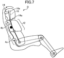
- FIG. 7 is a diagram schematically showing, as a comparative example, the movement of the spinal column of an occupant seated in a conventional vehicle seat, in a state in which a vehicle equipped with the vehicle seat is accelerated.
- the spinal column of an occupant D seated in the vehicle seat 1 is roughly located at a position indicated by the broken line 16 in FIG. 5 .
- the upper body of the occupant D is pressed against the seat back 4 by the inertia force.
- the upper body of the occupant pressed against the seat back 4 sinks in the seat back 4.
- a displacement (sinking amount) of each region of the upper body is determined mainly by the spring constant k2 of the hipbone supporting portion 4a and the spring constant k3 of the thorax supporting portion 4b.
- the spring constant k3 of the thorax supporting portion 4b and the spring constant k2 of the hipbone supporting portion 4a are set to be approximately equal to each other, so that the spinal column of the occupant D is moved to a position indicated by the solid line 16a.
- the head 14 of the occupant D is moved in a translational manner together with the thorax 12.
- the spring constant k3 of the thorax supporting portion 4b is set to be about 1 time to about 0.8 times the spring constant k2 of the hipbone supporting portion 4a. In this case, the head 14 and thorax 12 of the occupant D can be moved in an approximately translational manner.
- a displacement of a thorax supporting portion 4b during vehicle acceleration is small, so that the thorax of the occupant D is pushed forwardly relative to the head 14, and a force causing the head 14 of the occupant D to be rotated rearwardly about the cervical spine 14a serving as a supporting point is applied to the head 14.
- the spinal column of the occupant D is displaced to the position indicated by the solid line 16a in FIG.
- the spinal column of the occupant D sunk to the position indicated by the solid line 16a in FIG. 6 by vehicle acceleration is pushed back to the position indicated by the broken line 16 by a rebound force of the seat back 4, as shown in FIG. 6 .
- the spring constant k2 of the hipbone supporting portion 4a and the spring constant k3 of the thorax supporting portion 4b are adequately set.
- a vibrational damping property of the thorax supporting portion 4b is set such that a resonance magnification of the thorax supporting portion 4b becomes about 2 or less. In this case, it is possible to prevent a phenomenon that the upper body of the occupant D bounces on the seat back 4 by the rebound force.
- the spring constant k4 of the femur supporting portion 2b is set to be less than the spring constant k1 of the ischium supporting portion 2a.
- the spring constant k4 of the thorax supporting portion 4b is set to be about 0.4 times to about 0.6 times the spring constant k1 of the ischium supporting portion 2a.
- the seat back is configured such that the spring constant k3 of the thorax supporting portion 4b is equal to or less than the spring constant k2 of the hipbone supporting portion 4a ( FIG. 4 ). Therefore, the thorax 12 and head 14 of the occupant D pressed against the seat back 4 by the acceleration are moved in an approximately translational manner, so that a force causing the head 14 to be rotated rearwardly becomes smaller. This allows the occupant D to easily maintain a proper posture.
- the seat cushion is configured such that the spring constant k4 of the femur supporting portion 2b is less than the spring constant k1 of the ischium supporting portion 2a, so that the femur supporting portion 2b can be easily displaced during the pedal manipulation by the occupant D, thereby suppressing a negative influence on the pedal manipulation.
- the hipbone supporting portion 4a is provided to fall within the range of 70 mm to 230 mm as measured vertically upwardly from the position of the ischial tuberosity point 8a of the seated occupant D, so that it is possible to properly support the hipbones of any of a large number of occupants D having various physiques.
- the thorax supporting portion 4b is provided to fall within the range of 300 mm to 500 mm as measured vertically upwardly from the position of the ischial tuberosity point 8a of the seated occupant D, so that it is possible to properly support the thorax 12 of any of a large number of occupants D having various physiques.
- the femur supporting portion 2b is provided to fall within the range of 80 mm to 250 mm as measured horizontally forwardly from the position of the ischial tuberosity point 8a of the seated occupant D, so that it is possible to properly support the femurs 10 of any of a large number of occupants D having various physiques.
- the ischium supporting portion 2a is provided to fall within the range of 60 mm to 150 mm as measured horizontally forwardly from the position of rear ends 8b of the hipbones of the seated occupant D, so that it is possible to properly support the pelvis 8 of any of a large number of occupants D having various physiques.
Landscapes
- Engineering & Computer Science (AREA)
- Aviation & Aerospace Engineering (AREA)
- Transportation (AREA)
- Mechanical Engineering (AREA)
- Seats For Vehicles (AREA)
- Chair Legs, Seat Parts, And Backrests (AREA)
Abstract
Description
- The present invention relates to a vehicle seat, and particularly to a vehicle seat which comprises a seat back and a seat cushion.
-
JP 2015-199447A Patent Document 1, the seat cushion is configured in this manner, thereby enabling smooth getting-on/off a vehicle, while maintaining holding capability during seating. - Patent Document 1:
JP 2015-199447A - However, through researches of the present inventor, it was gradually discovered that a seat capable of providing satisfactory riding comfort still cannot be obtained only by improving the shape of a seat cushion as in the invention described in the
Patent Document 1. That is, only by adequately supporting the pelvis and femurs (thighbones) as in the invention described in thePatent Document 1, it is difficult for a seated occupant to maintain a proper driving position. As a result of various researches with a focus on the behavior of a human head during walking, the present inventor has found that a seated occupant can naturally maintain a proper driving position as if he/she were walking, by adequately holding a specific area of the upper body of the occupant in addition to the pelvis and femurs thereof. Specifically, natural human athletic ability frequently exhibited by a human during walking (ability of keeping a dynamic balance of the head) can be brought out by adequately supporting each region of the seated occupant, so that the occupant can naturally maintain a proper driving position. This makes it possible to provide a vehicle seat capable of providing significantly good riding comfort. - It is therefore an object of the present invention to provide a vehicle seat capable of enabling an occupant to naturally maintain a proper driving position.
- In order to solve the above problem, the present invention provides a vehicle seat which comprises a seat back including a hipbone supporting portion for supporting a hipbone of a seated occupant, and a thorax supporting portion provided above the hipbone support portion to support a thorax of the seated occupant; and a seat cushion including an ischium supporting portion oriented to extend approximately horizontally to support an ischial tuberosity point of the seated occupant, and a femur supporting portion provided forward of the ischium supporting portion to extend obliquely upwardly from the ischium supporting portion, wherein the seat back is configured such that a spring constant of the thorax supporting portion is equal to or less than a spring constant of the hipbone supporting portion.
- When a vehicle is accelerated, the body of an occupant seated in the vehicle seat is pressed against the seat back of the vehicle seat by the acceleration. In this situation, if the upper body of the occupant is not supported by an adequate holding force, a force will be applied to the head of the occupant to cause rotation thereof. Therefore, the occupant needs to strain at the neck so as to keep the head at an adequate angle and position, i.e., cannot easily maintain a proper posture. For example, in the situation where the upper body of the occupant is pressed against the seat back due to the acceleration of the vehicle, if a portion of the seat back which holds the thorax (rib cage) of the occupant is not displaced, a force is applied to the head of the occupant to cause the head to be rotated rearwardly about the cervical spine serving as a supporting point, leading to deterioration in riding comfort. In contrast, according to the above feature of the present invention, the seat back is configured such that the spring constant of the thorax supporting portion is equal to or less than the spring constant of the hipbone supporting portion. Therefore, the thorax and head of the occupant pressed against the seat back by the acceleration are moved in an approximately translational manner, so that a force causing the head to be rotated rearwardly becomes smaller. This allows the occupant to easily maintain a proper posture.
- Preferably, in the vehicle seat of the present invention, the seat cushion is configured such that a spring constant of the femur supporting portion is less than a spring constant of the ischium supporting portion.
- In the vehicle seat of the present invention, the ischium supporting portion for supporting the ischial tuberosity point is oriented to extend approximately horizontally, and the femur supporting portion is oriented to extend forwardly and obliquely upwardly from the ischium supporting portion. Thus, the pelvis of an occupant seated in the vehicle seat is naturally guided to the ischium supporting portion located between the seat back and the femur supporting portion, and the ischial tuberosity point of the occupant are properly supported by the approximately horizontal ischium supporting portion. In this way, the spine of the occupant is supported by the seat back, in a state in which it describes a natural S-shaped curve in side view. However, when the femur supporting portion is configured to extend forwardly and obliquely upwardly from the ischium supporting portion, it is likely to hinder a pedal manipulation by the foot of the occupant. In contrast, according to the above feature, the spring constant of the femur supporting portion is less than the spring constant of the ischium supporting portion, so that the femur supporting portion can be easily displaced during the pedal manipulation by the occupant, thereby suppressing a negative influence on the pedal manipulation.
- Preferably, in the vehicle seat of the present invention, the hipbone supporting portion is provided to fall within a range of 70 mm to 230 mm as measured vertically upwardly from a position of the ischial tuberosity point of the seated occupant.
- According to this feature, the hipbone supporting portion is provided to fall within the range of 70 mm to 230 mm as measured vertically upwardly from the position of the ischial tuberosity point of the seated occupant, so that it is possible to properly support the hipbones of any of a large number of occupants having various physiques.
- Preferably, in the vehicle seat of the present invention, the thorax supporting portion is provided to fall within a range of 300 mm to 500 mm as measured vertically upwardly from the position of the ischial tuberosity point of the seated occupant.
- According to this feature, the thorax supporting portion is provided to fall within the range of 300 mm to 500 mm as measured vertically upwardly from the position of the ischial tuberosity point of the seated occupant, so that it is possible to properly support the thorax of any of a large number of occupants having various physiques.
- Preferably, in the vehicle seat of the present invention, the femur supporting portion is provided to fall within a range of 80 mm to 250 mm as measured horizontally forwardly from a position of the ischial tuberosity point of the seated occupant.
- According to this feature, the femur supporting portion is provided to fall within the range of 80 mm to 250 mm as measured horizontally forwardly from the position of the ischial tuberosity point of the seated occupant, so that it is possible to properly support the femurs of any of a large number of occupants having various physiques.
- Preferably, in the vehicle seat of the present invention, the ischium supporting portion is provided to fall within a range of 60 mm to 150 mm as measured horizontally forwardly from a position of a rear end of the hipbones of the seated occupant.
- According to this feature, the ischium supporting portion is provided to fall within the range of 60 mm to 150 mm as measured horizontally forwardly from the position of the rear ends of the hipbones of the seated occupant, so that it is possible to properly support the pelvis of any of a large number of occupants having various physiques.
- The vehicle seat of the present invention can enable an occupant to naturally maintain a proper driving position.
-
-
FIG. 1 is a schematic diagram showing the entirety of a vehicle seat according to one embodiment of the present invention. -
FIG. 2 is a diagram illustrating the support of the bones of an occupant by the vehicle seat according to this embodiment. -
FIG. 3 is a diagram illustrating the support of the pelvis of the occupant by the vehicle seat according to this embodiment. -
FIG. 4 is a diagram specifically showing dimensions of various portions of the vehicle seat according to this embodiment. -
FIG. 5 is a diagram schematically showing the movement of the spinal column of an occupant seated in the vehicle seat according to this embodiment, in a state in which a vehicle equipped with the vehicle seat is accelerated. -
FIG. 6 is a diagram schematically showing the movement of the spinal column of the occupant seated in the vehicle seat according to this embodiment, in a state in which the vehicle is decelerated. -
FIG. 7 is a diagram schematically showing, as a comparative example, the movement of the spinal column of an occupant seated in a conventional vehicle seat, in a state in which a vehicle equipped with the vehicle seat is accelerated. - With reference to the accompanying drawings, a vehicle seat according to one preferred embodiment of the present invention will now be described.
-
FIG. 1 is a schematic diagram showing the entirety of the vehicle seat according to this embodiment.FIG. 2 is a diagram illustrating the support of the bones of an occupant by the vehicle seat according to this embodiment.FIG. 3 is a diagram illustrating the support of the pelvis of the occupant by the vehicle seat according to this embodiment.FIG. 4 is a diagram specifically showing dimensions of various portions of the vehicle seat according to this embodiment. - As shown in
FIG. 1 , thevehicle seat 1 according to this embodiment comprises aseat cushion 2, aseat back 4, and a headrest 6. Each of theseat cushion 2, theseat back 4 and the headrest 6 comprises a frame made of metal, an elastic member, and a cushioning member made of urethane or the like and formed to wrap the frame and the elastic member (these components are not shown). - The
seat cushion 2 comprises anischium supporting portion 2a oriented to extend approximately horizontally to supportischial tuberosity point 8a of an occupant D seated in the vehicle seat 1 (the occupant D is supported by theseat cushion 2 at theischial tuberosity point 8a), and afemur supporting portion 2b provided forward of theischium supporting portion 2a to extend obliquely upwardly from theischium supporting portion 2a. It should be noted here that, as used in this specification, the term "forward direction" of thevehicle seat 1 means a direction toward a side opposite to theseat back 4. Further, although thevehicle seat 1 in this embodiment is a driver seat for a vehicle, the present invention can also be applied to any vehicle seat other than the driver seat, such as a front passenger seat for a vehicle. - The
seat back 4 comprises ahipbone supporting portion 4a for supporting the hipbones of the seated occupant D, and athorax supporting portion 4b provided above thehipbone support portion 4a to support the thorax of the seated occupant D. - The headrest 6 is attached to an upper end of the
seat back 4 and disposed to support the back of the head of the occupant D. - Next, with reference to
FIGS. 2 and3 , the support of the bones of the occupant by theseat cushion 2 and theseat back 4 will be described. InFIGS. 2 and3 , for illustrative purposes, the occupant D is shown by the bones thereof. - As shown in
FIG. 2 , the occupant D is seated in thevehicle seat 1, while theischial tuberosity point 8a thereof, which are lower ends of the hipbones of thepelvis 8, and the vicinity thereof, are supported from therebelow by theischium supporting portion 2a of theseat cushion 2. Further, the occupant D is seated while the vicinities of the middles of thefemurs 10 thereof are supported from therebelow in an obliquely rearward direction by thefemur supporting portion 2b of theseat cushion 2. Specifically, thefemur supporting portion 2b of theseat cushion 2 is inclined such that it becomes gradually higher in the forward direction of thevehicle seat 1, so that, due to this inclination, the occupant D seated in thevehicle seat 1 is displaced toward a rearward side of thevehicle seat 1, and the back of the occupant D is moderately pressed against the seat back 4. Here, a desirable inclination angle of thefemur supporting portion 2b with respect to a horizontal plane depends on a height directional length from a heel point to a hip point of the seated occupant. Specifically, when the height directional length is 255 mm, the inclination angle is in the range of about 18 to 19 degrees, and when the height directional length is 300 mm, the inclination angle is in the range of about 15 to 16 degrees - Further, the occupant D is seated while
rear ends 8b of the hipbones of thepelvis 8 thereof are supported from therebehind by thehipbone supporting portion 4a of the seat back 4. Further, the occupant D is seated while thethorax 12 thereof is supported from therebehind, around a center-of-gravity point 12a of thethorax 12, by thethorax supporting portion 4b of the seat back 4. Generally, the center-of-gravity point 12a of thethorax 12 is located in the vicinity of the 7th thoracic vertebra of a human body. Preferably, thethorax supporting portion 4b is configured to support thethorax 12 with an area covering about 2.5 times the width of the thoracic vertebra, around the center-of-gravity point 12a thereof, thereby prevent an excessively large bending force from acting on the spinal column. -
FIG. 3 is a diagram enlargedly showing thepelvis 8 of the occupant D supported by thevehicle seat 1. As shown inFIG. 3 , theischial tuberosity point 8a of thepelvis 8 of the occupant D are supported from therebelow by theischium supporting portion 2a oriented to extend approximately horizontally. Further, because, due to the inclination of thefemur supporting portion 2b, the back of the occupant D is moderately pressed against the seat back 4, the rear ends 8b of the hipbones of thepelvis 8 are supported from therebehind by thehipbone supporting portion 4a. As above, when the occupant D is simply seated in thevehicle seat 1, thepelvis 8 of the occupant D is guided to the loweredischium supporting portion 2a of thevehicle seat 1, and erected at an adequate angle. Further, thepelvis 8 of the occupant D is supported from two directions by theischial tuberosity point 8a and therear ends 8b of the hipbones, so that it is held at a proper position and at a proper angle. - Next, with reference to
FIG. 4 , the position of each portion in thevehicle seat 1 according to this embodiment will be described in detail. - As shown in
FIG. 4 , theischium supporting portion 2a of theseat cushion 2 is is provided to fall within the range of 60 mm to 150 mm as measured horizontally forwardly from the position of therear ends 8b of the hipbones of the seated occupant D. - The
femur supporting portion 2b of theseat cushion 2 is provided to fall within the range of 80 mm to 250 mm as measured horizontally forwardly from the position of theischial tuberosity point 8a of the seated occupant D. - Further, the
hipbone supporting portion 4a of the seat back 4 is provided to fall within the range of 70 mm to 230 mm as measured vertically upwardly from the position of theischial tuberosity point 8a of the seated occupant D. - The
thorax supporting portion 4b of the seat back 4 is provided to fall within the range of 300 mm to 500 mm as measured vertically upwardly from the position of theischial tuberosity point 8a of the seated occupant D. - The above positions of the
ischium supporting portion 2a, thefemur supporting portion 2b, thehipbone supporting portion 4a and thethorax supporting portion 4b have been set based on dimensions of a human body dummy model, wherein they can be adapted to various models from a small-size model (AF05) having a body height of 150 cm to a large-size model (DM95) having a body height of 189 cm. - By adequately setting a spring constant of each of the portions of the
vehicle seat 1 whose dimensions and positions are set in the above manner, thevehicle seat 1 can be configured to provide good riding comfort. Here, the spring constant of each of the portions of thevehicle seat 1 is measured by using an F-S meter. In this embodiment, the spring constant k1 [N/mm] of theischium supporting portion 2a is calculated by the following formula: k1 = 200 / X1 [N/mm], where X1 is a displacement [mm] of a disk having a diameter of 200 mm, occurring when the disk is placed onto the surface of theischium supporting portion 2a to apply a force of 200 [N] to theischium supporting portion 2a in a direction orthogonal to the surface of theischium supporting portion 2a. Similarly, the spring constant k4 [N/mm] of thefemur supporting portion 2b is calculated by the following formula: k4 = 200 / X4 [N/mm], where X4 is a displacement [mm] of a disk having a diameter of 200 mm, occurring when the disk is placed onto the surface of thefemur supporting portion 2b to apply a force of 200 [N] to theischium supporting portion 2a in a direction orthogonal to the surface of thefemur supporting portion 2b. - Further, the spring constant k2 [N/mm] of the
hipbone supporting portion 4a is calculated by the following formula: k2 = 100 / X2 [N/mm], where X2 is a displacement [mm] of a disk having a diameter of 100 mm, occurring when the disk is placed onto the surface of thehipbone supporting portion 4a to apply a force of 100 [N] to thehipbone supporting portion 4a in a direction orthogonal to the surface of thehipbone supporting portion 4a. The spring constant k3 [N/mm] of thethorax supporting portion 4b is calculated by the following formula: k3 = 100 / X3 [N/mm], where X3 is a displacement [mm] of a disk having a diameter of 100 mm, occurring when the disk is placed onto the surface of thethorax supporting portion 4b to apply a force of 100 [N] to thethorax supporting portion 4b in a direction orthogonal to the surface of thethorax supporting portion 4b. - In this embodiment, the spring constant k1 of the
ischium supporting portion 2a and the spring constant k4 of thefemur supporting portion 2b measured in the above manner are set, respectively, to about 5 [N/mm] and about 2 [N/mm]. Further, the spring constant k2 of thehipbone supporting portion 4a and the spring constant k3 of thethorax supporting portion 4b measured in the above manner are set, respectively, to about 3 [N/mm] and about 3 [N/mm] - Next, with reference to
FIGS. 5 to 7 , the operation of thevehicle seat 1 according to this embodiment will be described. -
FIG. 5 is a diagram schematically showing the movement of the spinal column of an occupant seated in thevehicle seat 1 according to this embodiment, in a state in which a vehicle equipped with the vehicle is accelerated.FIG. 6 is a diagram schematically showing the movement of the spinal column of the occupant seated in the vehicle seat according to this embodiment, in a state in which the vehicle is decelerated.FIG. 7 is a diagram schematically showing, as a comparative example, the movement of the spinal column of an occupant seated in a conventional vehicle seat, in a state in which a vehicle equipped with the vehicle seat is accelerated. - As shown in
FIG. 5 , when a vehicle equipped with thevehicle seat 1 is stopped, or is traveling at a constant vehicle speed, the spinal column of an occupant D seated in thevehicle seat 1 is roughly located at a position indicated by thebroken line 16 inFIG. 5 . When the vehicle is accelerated from this state, the upper body of the occupant D is pressed against the seat back 4 by the inertia force. The upper body of the occupant pressed against the seat back 4 sinks in the seat back 4. In this situation, a displacement (sinking amount) of each region of the upper body is determined mainly by the spring constant k2 of thehipbone supporting portion 4a and the spring constant k3 of thethorax supporting portion 4b. - In this embodiment, the spring constant k3 of the
thorax supporting portion 4b and the spring constant k2 of thehipbone supporting portion 4a are set to be approximately equal to each other, so that the spinal column of the occupant D is moved to a position indicated by thesolid line 16a. As a result, thehead 14 of the occupant D is moved in a translational manner together with thethorax 12. Preferably, the spring constant k3 of thethorax supporting portion 4b is set to be about 1 time to about 0.8 times the spring constant k2 of thehipbone supporting portion 4a. In this case, thehead 14 andthorax 12 of the occupant D can be moved in an approximately translational manner. Therefore, almost no force causing thehead 14 of the occupant D to be rotated rearwardly is applied to thehead 14, so that the occupant D needs not strain at the neck so as to keep the position of thehead 14 during vehicle acceleration, i.e., can easily maintain a natural posture. That is, even during vehicle acceleration, the occupant D can naturally maintain the position of thehead 14 as if he/she were walking, and can stably keep the direction of the gaze. - On the other hand, in a conventional vehicle seat as shown in
FIG. 7 as a comparative example, during vehicle acceleration, the spinal column of an occupant D is disposed from a position indicated by thebroken line 16 to a position indicated by thesolid line 16a. As shown inFIG. 7 , in the conventional vehicle seat, a displacement of athorax supporting portion 4b during vehicle acceleration is small, so that the thorax of the occupant D is pushed forwardly relative to thehead 14, and a force causing thehead 14 of the occupant D to be rotated rearwardly about thecervical spine 14a serving as a supporting point is applied to thehead 14. Thus, during vehicle acceleration, the spinal column of the occupant D is displaced to the position indicated by thesolid line 16a inFIG. 7 , so that thehead 14 of the occupant D is rotated rearwardly, causing deviation of the direction of the gaze. In order to avoid such a rearward rotation of thehead 14, the occupant D needs to strain at the neck so as to maintain the position of thehead 14, which becomes a factor for giving the occupant D a feeling of fatigue. - Subsequently, when the vehicle is decelerated (when the occupant returns an accelerator pedal to end the vehicle acceleration), the spinal column of the occupant D sunk to the position indicated by the
solid line 16a inFIG. 6 by vehicle acceleration is pushed back to the position indicated by thebroken line 16 by a rebound force of the seat back 4, as shown inFIG. 6 . In thevehicle seat 1 according to this embodiment, the spring constant k2 of thehipbone supporting portion 4a and the spring constant k3 of thethorax supporting portion 4b are adequately set. Thus, upon the end of vehicle acceleration, the spinal column of the occupant D is naturally returned to the original position before vehicle acceleration, by the rebound force of the seat back 4. Preferably, a vibrational damping property of thethorax supporting portion 4b is set such that a resonance magnification of thethorax supporting portion 4b becomes about 2 or less. In this case, it is possible to prevent a phenomenon that the upper body of the occupant D bounces on the seat back 4 by the rebound force. - Further, in the
vehicle seat 1 according to this embodiment, the spring constant k4 of thefemur supporting portion 2b is set to be less than the spring constant k1 of theischium supporting portion 2a. Thus, when an occupant D seated in thevehicle seat 1 presses down on an accelerator pedal or the like, thefemur supporting portion 2b is easily depressed by a relatively weak force, without hindering the leg of the occupant D from manipulating the accelerator pedal or the like. Preferably, the spring constant k4 of thethorax supporting portion 4b is set to be about 0.4 times to about 0.6 times the spring constant k1 of theischium supporting portion 2a. - In the
vehicle seat 1 according to the above embodiment, the seat back is configured such that the spring constant k3 of thethorax supporting portion 4b is equal to or less than the spring constant k2 of thehipbone supporting portion 4a (FIG. 4 ). Therefore, thethorax 12 andhead 14 of the occupant D pressed against the seat back 4 by the acceleration are moved in an approximately translational manner, so that a force causing thehead 14 to be rotated rearwardly becomes smaller. This allows the occupant D to easily maintain a proper posture. - In the
vehicle seat 1 according to the above embodiment, the seat cushion is configured such that the spring constant k4 of thefemur supporting portion 2b is less than the spring constant k1 of theischium supporting portion 2a, so that thefemur supporting portion 2b can be easily displaced during the pedal manipulation by the occupant D, thereby suppressing a negative influence on the pedal manipulation. - In the
vehicle seat 1 according to the above embodiment, thehipbone supporting portion 4a is provided to fall within the range of 70 mm to 230 mm as measured vertically upwardly from the position of theischial tuberosity point 8a of the seated occupant D, so that it is possible to properly support the hipbones of any of a large number of occupants D having various physiques. - In the
vehicle seat 1 according to the above embodiment, thethorax supporting portion 4b is provided to fall within the range of 300 mm to 500 mm as measured vertically upwardly from the position of theischial tuberosity point 8a of the seated occupant D, so that it is possible to properly support thethorax 12 of any of a large number of occupants D having various physiques. - In the
vehicle seat 1 according to the above embodiment, thefemur supporting portion 2b is provided to fall within the range of 80 mm to 250 mm as measured horizontally forwardly from the position of theischial tuberosity point 8a of the seated occupant D, so that it is possible to properly support thefemurs 10 of any of a large number of occupants D having various physiques. - In the
vehicle seat 1 according to the above embodiment, theischium supporting portion 2a is provided to fall within the range of 60 mm to 150 mm as measured horizontally forwardly from the position ofrear ends 8b of the hipbones of the seated occupant D, so that it is possible to properly support thepelvis 8 of any of a large number of occupants D having various physiques. -
- 1:
- vehicle seat
- 2:
- seat cushion
- 2a:
- ischium supporting portion
- 2b:
- femur supporting portion
- 4:
- seat back
- 4a:
- hipbone supporting portion
- 4b:
- thorax supporting portion
- 6:
- headrest
- 8:
- pelvis
- 8a:
- ischial tuberosity point
- 8b:
- rear end of hipbone
- 10:
- femur
- 12:
- thorax
- 12a:
- center-of-gravity point of thorax
- 14:
- head
- 14a:
- cervical spine
Claims (6)
- A vehicle seat comprising:a seat back including a hipbone supporting portion for supporting a hipbone of a seated occupant, and a thorax supporting portion provided above the hipbone support portion to support a thorax of the seated occupant; anda seat cushion including an ischium supporting portion oriented to extend approximately horizontally to support an ischial tuberosity point of the seated occupant, and a femur supporting portion provided forward of the ischium supporting portion to extend obliquely upwardly from the ischium supporting portion,wherein the seat back is configured such that a spring constant of the thorax supporting portion is equal to or less than a spring constant of the hipbone supporting portion.
- The vehicle seat according to claim 1, wherein the seat cushion is configured such that a spring constant of the femur supporting portion is less than a spring constant of the ischium supporting portion.
- The vehicle seat according to claim 1 or 2, wherein the hipbone supporting portion is provided to fall within a range of 70 mm to 230 mm as measured vertically upwardly from a position of the ischial tuberosity point of the seated occupant.
- The vehicle seat according to any one of claims 1 to 3, wherein the thorax supporting portion is provided to fall within a range of 300 mm to 500 mm as measured vertically upwardly from a position of the ischial tuberosity point of the seated occupant.
- The vehicle seat according to any one of claims 1 to 4, wherein the femur supporting portion is provided to fall within a range of 80 mm to 250 mm as measured horizontally forwardly from a position of the ischial tuberosity point of the seated occupant.
- The vehicle seat according to any one of claims 1 to 4, wherein the ischium supporting portion is provided to fall within the range of 60 mm to 150 mm as measured horizontally forwardly from a position of a rear end of the hipbones of the seated occupant.
Applications Claiming Priority (2)
| Application Number | Priority Date | Filing Date | Title |
|---|---|---|---|
| JP2017145338A JP6940995B2 (en) | 2017-07-27 | 2017-07-27 | Vehicle seat |
| PCT/JP2018/028283 WO2019022237A1 (en) | 2017-07-27 | 2018-07-27 | Vehicle seat |
Publications (2)
| Publication Number | Publication Date |
|---|---|
| EP3659860A4 EP3659860A4 (en) | 2020-06-03 |
| EP3659860A1 true EP3659860A1 (en) | 2020-06-03 |
Family
ID=65040316
Family Applications (1)
| Application Number | Title | Priority Date | Filing Date |
|---|---|---|---|
| EP18837938.2A Pending EP3659860A1 (en) | 2017-07-27 | 2018-07-27 | Vehicle seat |
Country Status (5)
| Country | Link |
|---|---|
| US (1) | US11400842B2 (en) |
| EP (1) | EP3659860A1 (en) |
| JP (1) | JP6940995B2 (en) |
| CN (1) | CN110944871B (en) |
| WO (1) | WO2019022237A1 (en) |
Families Citing this family (2)
| Publication number | Priority date | Publication date | Assignee | Title |
|---|---|---|---|---|
| JP7806400B2 (en) * | 2021-06-09 | 2026-01-27 | 株式会社アイシン | Occupant detection device, method, and program |
| US11744375B2 (en) | 2021-07-14 | 2023-09-05 | Anthro Form, Llc | Seat configuration |
Family Cites Families (10)
| Publication number | Priority date | Publication date | Assignee | Title |
|---|---|---|---|---|
| JP3214282B2 (en) * | 1995-03-06 | 2001-10-02 | トヨタ自動車株式会社 | Vehicle seat structure |
| JP2002052616A (en) * | 2000-08-10 | 2002-02-19 | Bridgestone Corp | Vehicle seat |
| JP2003180481A (en) * | 2001-12-20 | 2003-07-02 | Delta Tooling Co Ltd | Seat |
| JP4709496B2 (en) | 2004-04-02 | 2011-06-22 | 株式会社デルタツーリング | Sheet structure |
| JP5153345B2 (en) * | 2005-12-28 | 2013-02-27 | 株式会社デルタツーリング | Vehicle seat |
| EP2623367B1 (en) * | 2010-10-01 | 2022-11-02 | Nissan Motor Co., Ltd. | Vehicle seat and stiffness setting method for vehicle seat |
| EP2692579A4 (en) * | 2011-03-31 | 2014-09-03 | Ts Tech Co Ltd | Seat cushion and vehicle seat |
| JP6032970B2 (en) * | 2012-06-28 | 2016-11-30 | テイ・エス テック株式会社 | Vehicle seat |
| JP6438210B2 (en) | 2014-04-09 | 2018-12-12 | 株式会社タチエス | Vehicle seat |
| US12187840B2 (en) * | 2020-03-27 | 2025-01-07 | Inoac Corporation | Vehicle cushion pad and vehicle seat cushion |
-
2017
- 2017-07-27 JP JP2017145338A patent/JP6940995B2/en active Active
-
2018
- 2018-07-27 EP EP18837938.2A patent/EP3659860A1/en active Pending
- 2018-07-27 US US16/633,766 patent/US11400842B2/en active Active
- 2018-07-27 WO PCT/JP2018/028283 patent/WO2019022237A1/en not_active Ceased
- 2018-07-27 CN CN201880048983.2A patent/CN110944871B/en active Active
Also Published As
| Publication number | Publication date |
|---|---|
| WO2019022237A1 (en) | 2019-01-31 |
| JP6940995B2 (en) | 2021-09-29 |
| US20200215945A1 (en) | 2020-07-09 |
| US11400842B2 (en) | 2022-08-02 |
| EP3659860A4 (en) | 2020-06-03 |
| CN110944871B (en) | 2022-09-02 |
| JP2019025991A (en) | 2019-02-21 |
| CN110944871A (en) | 2020-03-31 |
Similar Documents
| Publication | Publication Date | Title |
|---|---|---|
| US9873364B2 (en) | Vehicle seat | |
| JP6097823B2 (en) | Vehicle seat with lumbar support | |
| US10543764B2 (en) | Vehicle seat and stiffness setting method for vehicle seat | |
| JP4737501B2 (en) | Vehicle seat | |
| US8162402B2 (en) | Vehicular seats | |
| US9963055B2 (en) | Leg rest apparatus for vehicle seat | |
| JP6557462B2 (en) | Lumber support structure and seat structure | |
| US11400842B2 (en) | Vehicle seat | |
| EP3738823B1 (en) | Vehicle seat structure | |
| JP5625811B2 (en) | Standing seat device | |
| JP6972512B2 (en) | Vehicle seat | |
| JP7240589B2 (en) | vehicle seat structure | |
| JP4488854B2 (en) | Vehicle seat | |
| JP2013163403A (en) | Vehicle seat | |
| US11377008B2 (en) | Vehicle seat | |
| JP2008230397A (en) | Vehicle seat structure | |
| JP2005176958A (en) | Vehicle seat | |
| JP2020050254A (en) | Vehicle seat structure |
Legal Events
| Date | Code | Title | Description |
|---|---|---|---|
| STAA | Information on the status of an ep patent application or granted ep patent |
Free format text: STATUS: THE INTERNATIONAL PUBLICATION HAS BEEN MADE |
|
| PUAI | Public reference made under article 153(3) epc to a published international application that has entered the european phase |
Free format text: ORIGINAL CODE: 0009012 |
|
| STAA | Information on the status of an ep patent application or granted ep patent |
Free format text: STATUS: REQUEST FOR EXAMINATION WAS MADE |
|
| 17P | Request for examination filed |
Effective date: 20200217 |
|
| A4 | Supplementary search report drawn up and despatched |
Effective date: 20200508 |
|
| AK | Designated contracting states |
Kind code of ref document: A1 Designated state(s): AL AT BE BG CH CY CZ DE DK EE ES FI FR GB GR HR HU IE IS IT LI LT LU LV MC MK MT NL NO PL PT RO RS SE SI SK SM TR |
|
| AX | Request for extension of the european patent |
Extension state: BA ME |
|
| DAV | Request for validation of the european patent (deleted) | ||
| DAX | Request for extension of the european patent (deleted) | ||
| STAA | Information on the status of an ep patent application or granted ep patent |
Free format text: STATUS: EXAMINATION IS IN PROGRESS |
|
| 17Q | First examination report despatched |
Effective date: 20230823 |