EP3659853A1 - Power supply system for fuel cell and fuel cell system - Google Patents
Power supply system for fuel cell and fuel cell system Download PDFInfo
- Publication number
- EP3659853A1 EP3659853A1 EP18837414.4A EP18837414A EP3659853A1 EP 3659853 A1 EP3659853 A1 EP 3659853A1 EP 18837414 A EP18837414 A EP 18837414A EP 3659853 A1 EP3659853 A1 EP 3659853A1
- Authority
- EP
- European Patent Office
- Prior art keywords
- fuel cell
- converter
- 24vdc
- power supply
- controller
- Prior art date
- Legal status (The legal status is an assumption and is not a legal conclusion. Google has not performed a legal analysis and makes no representation as to the accuracy of the status listed.)
- Granted
Links
Images
Classifications
-
- B—PERFORMING OPERATIONS; TRANSPORTING
- B60—VEHICLES IN GENERAL
- B60L—PROPULSION OF ELECTRICALLY-PROPELLED VEHICLES; SUPPLYING ELECTRIC POWER FOR AUXILIARY EQUIPMENT OF ELECTRICALLY-PROPELLED VEHICLES; ELECTRODYNAMIC BRAKE SYSTEMS FOR VEHICLES IN GENERAL; MAGNETIC SUSPENSION OR LEVITATION FOR VEHICLES; MONITORING OPERATING VARIABLES OF ELECTRICALLY-PROPELLED VEHICLES; ELECTRIC SAFETY DEVICES FOR ELECTRICALLY-PROPELLED VEHICLES
- B60L3/00—Electric devices on electrically-propelled vehicles for safety purposes; Monitoring operating variables, e.g. speed, deceleration or energy consumption
-
- H—ELECTRICITY
- H01—ELECTRIC ELEMENTS
- H01M—PROCESSES OR MEANS, e.g. BATTERIES, FOR THE DIRECT CONVERSION OF CHEMICAL ENERGY INTO ELECTRICAL ENERGY
- H01M8/00—Fuel cells; Manufacture thereof
- H01M8/04—Auxiliary arrangements, e.g. for control of pressure or for circulation of fluids
- H01M8/04298—Processes for controlling fuel cells or fuel cell systems
- H01M8/04694—Processes for controlling fuel cells or fuel cell systems characterised by variables to be controlled
- H01M8/04858—Electric variables
- H01M8/04925—Power, energy, capacity or load
-
- B—PERFORMING OPERATIONS; TRANSPORTING
- B60—VEHICLES IN GENERAL
- B60L—PROPULSION OF ELECTRICALLY-PROPELLED VEHICLES; SUPPLYING ELECTRIC POWER FOR AUXILIARY EQUIPMENT OF ELECTRICALLY-PROPELLED VEHICLES; ELECTRODYNAMIC BRAKE SYSTEMS FOR VEHICLES IN GENERAL; MAGNETIC SUSPENSION OR LEVITATION FOR VEHICLES; MONITORING OPERATING VARIABLES OF ELECTRICALLY-PROPELLED VEHICLES; ELECTRIC SAFETY DEVICES FOR ELECTRICALLY-PROPELLED VEHICLES
- B60L58/00—Methods or circuit arrangements for monitoring or controlling batteries or fuel cells, specially adapted for electric vehicles
- B60L58/30—Methods or circuit arrangements for monitoring or controlling batteries or fuel cells, specially adapted for electric vehicles for monitoring or controlling fuel cells
-
- H—ELECTRICITY
- H02—GENERATION; CONVERSION OR DISTRIBUTION OF ELECTRIC POWER
- H02J—ELECTRIC POWER NETWORKS; CIRCUIT ARRANGEMENTS OR SYSTEMS FOR SUPPLYING OR DISTRIBUTING ELECTRIC POWER; SYSTEMS FOR STORING ELECTRIC ENERGY
- H02J1/00—Circuit arrangements for DC mains or DC distribution networks
- H02J1/10—Parallel operation of DC sources
-
- H—ELECTRICITY
- H02—GENERATION; CONVERSION OR DISTRIBUTION OF ELECTRIC POWER
- H02J—ELECTRIC POWER NETWORKS; CIRCUIT ARRANGEMENTS OR SYSTEMS FOR SUPPLYING OR DISTRIBUTING ELECTRIC POWER; SYSTEMS FOR STORING ELECTRIC ENERGY
- H02J7/00—Circuit arrangements for charging or discharging batteries or for supplying loads from batteries
- H02J7/34—Parallel operation in networks using both storage and other DC sources, e.g. providing buffering
-
- H—ELECTRICITY
- H01—ELECTRIC ELEMENTS
- H01M—PROCESSES OR MEANS, e.g. BATTERIES, FOR THE DIRECT CONVERSION OF CHEMICAL ENERGY INTO ELECTRICAL ENERGY
- H01M2250/00—Fuel cells for particular applications; Specific features of fuel cell system
- H01M2250/20—Fuel cells in motive systems, e.g. vehicle, ship, plane
-
- H—ELECTRICITY
- H02—GENERATION; CONVERSION OR DISTRIBUTION OF ELECTRIC POWER
- H02J—ELECTRIC POWER NETWORKS; CIRCUIT ARRANGEMENTS OR SYSTEMS FOR SUPPLYING OR DISTRIBUTING ELECTRIC POWER; SYSTEMS FOR STORING ELECTRIC ENERGY
- H02J2101/00—Supply or distribution of decentralised, dispersed or local electric power generation
- H02J2101/20—Dispersed power generation using renewable energy sources
- H02J2101/30—Fuel cells
-
- Y—GENERAL TAGGING OF NEW TECHNOLOGICAL DEVELOPMENTS; GENERAL TAGGING OF CROSS-SECTIONAL TECHNOLOGIES SPANNING OVER SEVERAL SECTIONS OF THE IPC; TECHNICAL SUBJECTS COVERED BY FORMER USPC CROSS-REFERENCE ART COLLECTIONS [XRACs] AND DIGESTS
- Y02—TECHNOLOGIES OR APPLICATIONS FOR MITIGATION OR ADAPTATION AGAINST CLIMATE CHANGE
- Y02E—REDUCTION OF GREENHOUSE GAS [GHG] EMISSIONS, RELATED TO ENERGY GENERATION, TRANSMISSION OR DISTRIBUTION
- Y02E60/00—Enabling technologies; Technologies with a potential or indirect contribution to GHG emissions mitigation
- Y02E60/30—Hydrogen technology
- Y02E60/50—Fuel cells
-
- Y—GENERAL TAGGING OF NEW TECHNOLOGICAL DEVELOPMENTS; GENERAL TAGGING OF CROSS-SECTIONAL TECHNOLOGIES SPANNING OVER SEVERAL SECTIONS OF THE IPC; TECHNICAL SUBJECTS COVERED BY FORMER USPC CROSS-REFERENCE ART COLLECTIONS [XRACs] AND DIGESTS
- Y02—TECHNOLOGIES OR APPLICATIONS FOR MITIGATION OR ADAPTATION AGAINST CLIMATE CHANGE
- Y02T—CLIMATE CHANGE MITIGATION TECHNOLOGIES RELATED TO TRANSPORTATION
- Y02T10/00—Road transport of goods or passengers
- Y02T10/60—Other road transportation technologies with climate change mitigation effect
- Y02T10/70—Energy storage systems for electromobility, e.g. batteries
-
- Y—GENERAL TAGGING OF NEW TECHNOLOGICAL DEVELOPMENTS; GENERAL TAGGING OF CROSS-SECTIONAL TECHNOLOGIES SPANNING OVER SEVERAL SECTIONS OF THE IPC; TECHNICAL SUBJECTS COVERED BY FORMER USPC CROSS-REFERENCE ART COLLECTIONS [XRACs] AND DIGESTS
- Y02—TECHNOLOGIES OR APPLICATIONS FOR MITIGATION OR ADAPTATION AGAINST CLIMATE CHANGE
- Y02T—CLIMATE CHANGE MITIGATION TECHNOLOGIES RELATED TO TRANSPORTATION
- Y02T90/00—Enabling technologies or technologies with a potential or indirect contribution to GHG emissions mitigation
- Y02T90/40—Application of hydrogen technology to transportation, e.g. using fuel cells
Definitions
- the present disclosure relates to a fuel cell power supply system and a fuel cell system, which belongs to the technical field of vehicle fuel cell power systems.
- Fuel cell bus is an important application in the field of fuel cells. This new technology is strongly supported by the national policies of the People's Republic of China, which has become an important force in promoting the development of fuel cells.
- fuel cell vehicle power system used on bus utilizes a storage battery and a 24VDC/DC converter of the vehicle to power the fuel cell system.
- the low voltage power supply to the fuel cell through the vehicle is relatively simple in structure for the present fuel cell system to use, but it has the following two disadvantages.
- First, the discharge capacity of the storage battery of the vehicle cannot meet the increasing fuel cell power, and different fuel cell systems have different low voltage power requirements, therefore such vehicle energy distribution cannot achieve large scale use.
- the vehicle supplies power to the fuel cell through the 24VDC/DC converter. Since, high voltage at the input end of the 24VDC/DC converter is taken from the boosting DC/DC converter of the fuel cell, the power undergoes a two-stage DC/DC conversion, resulting in large power loss and low energy efficiency.
- the Chinese patent with publication number CN1663838A , discloses a hybrid power system of a fuel cell vehicle.
- the electric energy output from the fuel cell stack is converted by a 24VDC/DC converter to power the fuel cell controller, which solves the problem of energy distribution of the vehicle when the low voltage power required by the fuel cell is excessive.
- the fluctuation of the output voltage of the 24VDC/DC converter will greatly shorten the lifetime of the voltage-sensitive electronic components, such as the fuel cell controller.
- the failure of the 24VDC/DC converter will lead to a sudden power outage of the existing fuel cell system and cause irreversible damage to the existing fuel system.
- the objective of the present disclosure is to provide a fuel cell power supply system and a fuel cell system, in order to solve the technical problem that the fuel cell stack cannot provide a stable and reliable low voltage power supply for the fuel cell system.
- the present disclosure provides a fuel cell power supply system, including a fuel cell stack, a 24VDC/DC converter, and a fuel cell controller.
- the high voltage input end of the 24VDC/DC converter is connected to the fuel cell stack, and the low voltage output end of the 24VDC/DC converter is connected to the low voltage busbar of the fuel cell.
- the low voltage busbar of the fuel cell is electrically connected to the fuel cell controller, and the storage battery for the fuel cell.
- a protective relay is arranged at the output end of the storage battery for the fuel cell, and the fuel cell controller is connected to and controls the protective relay.
- the fuel cell power supply system further includes a boosting DC/DC converter.
- the low voltage input end of the boosting DC/DC converter is connected to the fuel cell stack, and the high voltage output end of the boosting DC/DC converter is configured to be electrically connected to an in-vehicle high voltage electrical device.
- a first load relay is arranged between the fuel cell stack and the 24VDC/DC converter
- a second load relay is arranged between the fuel cell stack and the boosting DC/DC converter.
- the fuel cell controller is connected to and controls the first load relay and the second load relay.
- a CAN bus is arranged to connect between the fuel cell controller and the 24VDC/DC converter, and a CAN bus is arranged to connect between the fuel cell controller and the fuel cell stack.
- the present disclosure further provides a fuel cell system, including an in-vehicle device, a fuel cell power supply system, and a fuel cell accessory system.
- the fuel cell power supply system includes a fuel cell stack, a 24VDC/DC converter, and a fuel cell controller.
- the high voltage input end of the 24VDC/DC converter is connected to the fuel cell stack, and the low voltage output end of the 24VDC/DC converter is connected to a low voltage busbar of the fuel cell.
- the low voltage busbar of the fuel cell is electrically connected to the fuel cell controller, the fuel cell accessory system, and a storage battery for the fuel cell.
- a protective relay is arranged at the output end of the storage battery for the fuel cell, and the fuel cell controller is connected to and controls the protective relay.
- the fuel cell power supply system further includes a boosting DC/DC converter.
- the in-vehicle device includes an in-vehicle high voltage electrical device.
- the high voltage output end of the boosting DC/DC converter is electrically connected to the in-vehicle high voltage electrical device.
- a first load relay is arranged between the fuel cell stack and the 24VDC/DC converter
- a second load relay is arranged between the fuel cell stack and the boosting DC/DC converter.
- the fuel cell controller is connected to and controls the first load relay and the second load relay.
- the in-vehicle device further includes a vehicle controller and an in-vehicle low voltage power supply device.
- vehicle controller is connected to and communicates with the fuel cell controller, and the in-vehicle low voltage power supply device is electrically connected to the fuel cell controller.
- Both the low voltage output end of the 24VDC/DC converter and the output end of the storage battery for a fuel cell are connected to a low voltage busbar of the fuel cell, and the low voltage busbar of the fuel cell is used for supplying power for the fuel cell controller and the fuel cell accessory system.
- Connecting the low voltage busbas of the fuel cell to the storage battery for the fuel cell has two functions. Firstly, the voltage can be stabilized. Since the voltage at the output end of the DC/DC converter fluctuates, the storage battery for the fuel cell is added to eliminate as much as possible the impact of voltage fluctuation on power supply for the fuel cell controller and the fuel cell accessory system. Secondly, the influence on the low voltage power supply system caused by the failure of the 24VDC/DC converter can be avoided. Even if the 24VDC/DC converter suddenly fails, the storage battery for the fuel cell can also be used for supplying power, thereby guaranteeing the safety of the fuel cell system.
- the fuel cell controller protects the storage battery for the fuel cell from loss of power by controlling the on-off of the protective relay.
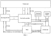
- FIG 1 is a schematic diagram of the configuration of the fuel cell system of the present disclosure.
- the fuel cell system of the present disclosure includes an in-vehicle device, a fuel cell power supply system, and a fuel cell accessory system (i.e. the electrical accessory in FIG. 1 ).
- the fuel cell power supply system is connected to the in-vehicle device and the fuel cell accessory system.
- the fuel cell accessory system includes a water pump, a fan, a solenoid valve along with other low voltage equipment.
- the in-vehicle device includes a vehicle controller, an in-vehicle high voltage electrical device, an in-vehicle low voltage power supply device, and other vehicle equipment.
- the fuel cell power supply system includes a fuel cell stack, a 24VDC/DC converter, a storage battery for the fuel cell, a fuel cell controller, a boosting DC/DC converter among other fuel cell equipment.
- the high voltage input end of the 24VDC/DC converter is connected to the fuel cell stack, and the low voltage output end of the 24VDC/DC converter is connected to a low voltage busbar of the fuel cell.
- the low voltage busbar of the fuel cell is connected to the fuel cell controller, the fuel cell accessory system, and the storage battery for the fuel cell.
- the fuel cell stack is further connected to the low voltage input end of the boosting DC/DC converter, and the high voltage output end of the boosting DC/DC converter is eletrically connected to the in-vehicle high voltage electrical device.
- the in-vehicle low voltage power supply device is also electrically connected to the fuel cell controller, and the vehicle controller is connected to and controls the fuel cell controller through a CAN bus.
- a protective relay is arranged at the output end of the storage battery for the fuel cell, and the fuel cell controller is connected to and controls the protective relay.
- the fuel cell controller protects the storage battery for the fuel cell from loss of power by controlling the on-off of the protective relay.
- a first load relay is arranged between the fuel cell stack and the 24VDC/DC converter, and a second load relay is arranged between the fuel cell stack and the boosting DC/DC converter.
- the fuel cell controller is connected to and controls the first load relay and the second load relay.
- a CAN bus is arranged to connect between the fuel cell controller and the 24VDC/DC converter, and a CAN bus is arranged to connect between the fuel cell controller and the fuel cell stack.
- the fuel cell controller is connected to and communicates with the 24VDC/DC converter and the fuel cell stack through the CAN bus.
- the 24VDC/DC converter Under a normal operating state, the 24VDC/DC converter is used to supply power to the fuel cell controller and the fuel cell electrical accessories. Meanwhile, a 24V storage battery for the fuel cell located at the output end of the 24VDC/DC converter, ensures the stability of the low voltage power supply and ensures short-term power supply in the case of failure of the 24VD/DC converter, so as to guarantee the safety of the fuel cell system.
Landscapes
- Engineering & Computer Science (AREA)
- Power Engineering (AREA)
- Life Sciences & Earth Sciences (AREA)
- Sustainable Development (AREA)
- Sustainable Energy (AREA)
- Mechanical Engineering (AREA)
- Transportation (AREA)
- Manufacturing & Machinery (AREA)
- Chemical & Material Sciences (AREA)
- Chemical Kinetics & Catalysis (AREA)
- Electrochemistry (AREA)
- General Chemical & Material Sciences (AREA)
- Fuel Cell (AREA)
- Electric Propulsion And Braking For Vehicles (AREA)
Abstract
Description
- The present disclosure relates to a fuel cell power supply system and a fuel cell system, which belongs to the technical field of vehicle fuel cell power systems.
- Compared with battery electric vehicles, fuel cell vehicles have the characteristics of long mileage range, short charging time and relatively zero pollution, are considered as the ultimate development direction of new energy vehicles. Fuel cell bus is an important application in the field of fuel cells. This new technology is strongly supported by the national policies of the People's Republic of China, which has become an important force in promoting the development of fuel cells.
- Currently in the market, fuel cell vehicle power system used on bus utilizes a storage battery and a 24VDC/DC converter of the vehicle to power the fuel cell system. The low voltage power supply to the fuel cell through the vehicle is relatively simple in structure for the present fuel cell system to use, but it has the following two disadvantages. First, the discharge capacity of the storage battery of the vehicle cannot meet the increasing fuel cell power, and different fuel cell systems have different low voltage power requirements, therefore such vehicle energy distribution cannot achieve large scale use. Second, the vehicle supplies power to the fuel cell through the 24VDC/DC converter. Since, high voltage at the input end of the 24VDC/DC converter is taken from the boosting DC/DC converter of the fuel cell, the power undergoes a two-stage DC/DC conversion, resulting in large power loss and low energy efficiency.
- The Chinese patent, with publication number
CN1663838A , discloses a hybrid power system of a fuel cell vehicle. In the hybrid power system, the electric energy output from the fuel cell stack is converted by a 24VDC/DC converter to power the fuel cell controller, which solves the problem of energy distribution of the vehicle when the low voltage power required by the fuel cell is excessive. However, the fluctuation of the output voltage of the 24VDC/DC converter will greatly shorten the lifetime of the voltage-sensitive electronic components, such as the fuel cell controller. Moreover, the failure of the 24VDC/DC converter will lead to a sudden power outage of the existing fuel cell system and cause irreversible damage to the existing fuel system. - The objective of the present disclosure is to provide a fuel cell power supply system and a fuel cell system, in order to solve the technical problem that the fuel cell stack cannot provide a stable and reliable low voltage power supply for the fuel cell system.
- In order to solve the above technical problem, the present disclosure provides a fuel cell power supply system, including a fuel cell stack, a 24VDC/DC converter, and a fuel cell controller. The high voltage input end of the 24VDC/DC converter is connected to the fuel cell stack, and the low voltage output end of the 24VDC/DC converter is connected to the low voltage busbar of the fuel cell. The low voltage busbar of the fuel cell is electrically connected to the fuel cell controller, and the storage battery for the fuel cell.
- Further, a protective relay is arranged at the output end of the storage battery for the fuel cell, and the fuel cell controller is connected to and controls the protective relay.
- Further, the fuel cell power supply system further includes a boosting DC/DC converter. The low voltage input end of the boosting DC/DC converter is connected to the fuel cell stack, and the high voltage output end of the boosting DC/DC converter is configured to be electrically connected to an in-vehicle high voltage electrical device.
- Further, a first load relay is arranged between the fuel cell stack and the 24VDC/DC converter, and a second load relay is arranged between the fuel cell stack and the boosting DC/DC converter. The fuel cell controller is connected to and controls the first load relay and the second load relay.
- Further, a CAN bus is arranged to connect between the fuel cell controller and the 24VDC/DC converter, and a CAN bus is arranged to connect between the fuel cell controller and the fuel cell stack.
- The present disclosure further provides a fuel cell system, including an in-vehicle device, a fuel cell power supply system, and a fuel cell accessory system. The fuel cell power supply system includes a fuel cell stack, a 24VDC/DC converter, and a fuel cell controller. The high voltage input end of the 24VDC/DC converter is connected to the fuel cell stack, and the low voltage output end of the 24VDC/DC converter is connected to a low voltage busbar of the fuel cell. The low voltage busbar of the fuel cell is electrically connected to the fuel cell controller, the fuel cell accessory system, and a storage battery for the fuel cell.
- Further, a protective relay is arranged at the output end of the storage battery for the fuel cell, and the fuel cell controller is connected to and controls the protective relay.
- Further, the fuel cell power supply system further includes a boosting DC/DC converter. The in-vehicle device includes an in-vehicle high voltage electrical device. The high voltage output end of the boosting DC/DC converter is electrically connected to the in-vehicle high voltage electrical device.
- Further, a first load relay is arranged between the fuel cell stack and the 24VDC/DC converter, and a second load relay is arranged between the fuel cell stack and the boosting DC/DC converter. The fuel cell controller is connected to and controls the first load relay and the second load relay.
- Further, the in-vehicle device further includes a vehicle controller and an in-vehicle low voltage power supply device. The vehicle controller is connected to and communicates with the fuel cell controller, and the in-vehicle low voltage power supply device is electrically connected to the fuel cell controller.
- The advantages of the present disclosure are as follows.
- Both the low voltage output end of the 24VDC/DC converter and the output end of the storage battery for a fuel cell are connected to a low voltage busbar of the fuel cell, and the low voltage busbar of the fuel cell is used for supplying power for the fuel cell controller and the fuel cell accessory system. Connecting the low voltage busbas of the fuel cell to the storage battery for the fuel cell has two functions. Firstly, the voltage can be stabilized. Since the voltage at the output end of the DC/DC converter fluctuates, the storage battery for the fuel cell is added to eliminate as much as possible the impact of voltage fluctuation on power supply for the fuel cell controller and the fuel cell accessory system. Secondly, the influence on the low voltage power supply system caused by the failure of the 24VDC/DC converter can be avoided. Even if the 24VDC/DC converter suddenly fails, the storage battery for the fuel cell can also be used for supplying power, thereby guaranteeing the safety of the fuel cell system.
- Further, by setting the protective relay at the output end of the storage battery for the fuel cell, the fuel cell controller protects the storage battery for the fuel cell from loss of power by controlling the on-off of the protective relay.
-
FIG 1 is a schematic diagram of the configuration of the fuel cell system of the present disclosure. - In order to make the objective, technical solution and advantages of the present disclosure more clear, the present disclosure is further described in detail in combination with the drawing and specific embodiments below.
- As shown in
FIG. 1 , the fuel cell system of the present disclosure includes an in-vehicle device, a fuel cell power supply system, and a fuel cell accessory system (i.e. the electrical accessory inFIG. 1 ). The fuel cell power supply system is connected to the in-vehicle device and the fuel cell accessory system. The fuel cell accessory system includes a water pump, a fan, a solenoid valve along with other low voltage equipment. The in-vehicle device includes a vehicle controller, an in-vehicle high voltage electrical device, an in-vehicle low voltage power supply device, and other vehicle equipment. The fuel cell power supply system includes a fuel cell stack, a 24VDC/DC converter, a storage battery for the fuel cell, a fuel cell controller, a boosting DC/DC converter among other fuel cell equipment. - Specifically, the high voltage input end of the 24VDC/DC converter is connected to the fuel cell stack, and the low voltage output end of the 24VDC/DC converter is connected to a low voltage busbar of the fuel cell. The low voltage busbar of the fuel cell is connected to the fuel cell controller, the fuel cell accessory system, and the storage battery for the fuel cell. The fuel cell stack is further connected to the low voltage input end of the boosting DC/DC converter, and the high voltage output end of the boosting DC/DC converter is eletrically connected to the in-vehicle high voltage electrical device. The in-vehicle low voltage power supply device is also electrically connected to the fuel cell controller, and the vehicle controller is connected to and controls the fuel cell controller through a CAN bus.
- In addition, a protective relay is arranged at the output end of the storage battery for the fuel cell, and the fuel cell controller is connected to and controls the protective relay. The fuel cell controller protects the storage battery for the fuel cell from loss of power by controlling the on-off of the protective relay. A first load relay is arranged between the fuel cell stack and the 24VDC/DC converter, and a second load relay is arranged between the fuel cell stack and the boosting DC/DC converter. The fuel cell controller is connected to and controls the first load relay and the second load relay. A CAN bus is arranged to connect between the fuel cell controller and the 24VDC/DC converter, and a CAN bus is arranged to connect between the fuel cell controller and the fuel cell stack. The fuel cell controller is connected to and communicates with the 24VDC/DC converter and the fuel cell stack through the CAN bus.
- The working process of the fuel cell system mentioned above is as follows.
- (1) After the vehicle is powered on, the low voltage power supply of the vehicle supplies power to the core part of the fuel cell controller, and the fuel cell controller performs the system self-test. After passing the self-test, the fuel cell controller begins to receive the control commands from the vehicle controller. In this process, the vehicle still needs to provide the necessary low voltage power supply.
- (2) When the fuel cell controller can receive the control commands from the vehicle controller, the fuel cell controller judges the current working state of the fuel cell stack, and then the fuel cell controller controls the load relays at ends of the stack to be turned on, wherein the load relays at ends of the stack includes the first load relay connected between the fuel cell stack and the 24VDC/DC converter, and the second load relay connected between the fuel cell stack and the boosting DC/DC converter.
- (3) When the load relays are turned on, the fuel cell controller calculates a target current according to the power required by the electrical accessories of the system and sends a command about the target current to the 24VDC/DC converter through the CAN bus. Then, the 24VDC/DC converter converts the electric current of the fuel cell stack to a low voltage power of 24V for the fuel cell system.
- Under a normal operating state, the 24VDC/DC converter is used to supply power to the fuel cell controller and the fuel cell electrical accessories. Meanwhile, a 24V storage battery for the fuel cell located at the output end of the 24VDC/DC converter, ensures the stability of the low voltage power supply and ensures short-term power supply in the case of failure of the 24VD/DC converter, so as to guarantee the safety of the fuel cell system.
Claims (10)
- A fuel cell power supply system, comprising a fuel cell stack, a 24VDC/DC converter, and a fuel cell controller, a high voltage input end of the 24VDC/DC converter is connected to the fuel cell stack, characterized in that, a low voltage output end of the 24VDC/DC converter is connected to a low voltage busbar of the fuel cell; the low voltage busbar of the fuel cell is electrically connected to the fuel cell controller and a storage battery for the fuel cell.
- The fuel cell power supply system according to claim 1, characterized in that, a protective relay is arranged at an output end of the storage battery for the fuel cell, and the fuel cell controller is connected to and controls the protective relay.
- The fuel cell power supply system according to claim 1 or 2, characterized in that, further comprising a boosting DC/DC converter; a low voltage input end of the boosting DC/DC converter is connected to the fuel cell stack, and a high voltage output end of the boosting DC/DC converter is configured to be electrically connected to an in-vehicle high voltage electrical device.
- The fuel cell power supply system according to claim 3, characterized in that, a first load relay is arranged between the fuel cell stack and the 24VDC/DC converter, and a second load relay is arranged between the fuel cell stack and the boosting DC/DC converter; the fuel cell controller is connected to and controls the first load relay and the second load relay.
- The fuel cell power supply system according to claim 1 or 2, characterized in that, a CAN bus is arranged to connect between the fuel cell controller and the 24VDC/DC converter, and a CAN bus is arranged to connect between the fuel cell controller and the fuel cell stack.
- A fuel cell system, comprising an in-vehicle device, a fuel cell power supply system, and a fuel cell accessory system; the fuel cell power supply system comprises a fuel cell stack, a 24VDC/DC converter and a fuel cell controller; a high voltage input end of the 24VDC/DC converter is connected to the fuel cell stack, characterized in that, a low voltage output end of the 24VDC/DC converter is connected to a low voltage busbar of the fuel cell; the low voltage busbar of the fuel cell is electrically connected to the fuel cell controller, the fuel cell accessory system, and a storage battery for the fuel cell.
- The fuel cell system according to claim 6, characterized in that, a protective relay is arranged at an output end of the storage battery for the fuel cell, and the fuel cell controller is connected to and controls the protective relay.
- The fuel cell system according to claim 6 or 7, characterized in that, the fuel cell power supply system further comprises a boosting DC/DC converter; the in-vehicle device comprises an in-vehicle high voltage electrical device; a high voltage output end of the boosting DC/DC converter is electrically connected to in-vehicle high voltage electrical device.
- The fuel cell system according to claim 8, characterized in that, a first load relay is arranged between the fuel cell stack and the 24VDC/DC converter, and a second load relay is arranged between the fuel cell stack and the boosting DC/DC converter; the fuel cell controller is connected to and controls the first load relay and the second load relay.
- The fuel cell system according to claim 6 or 7, characterized in that, the in-vehicle device further comprises a vehicle controller and an in-vehicle low voltage power supply device; the vehicle controller is connected to, and communicates with the fuel cell controller, and the in-vehicle low voltage power supply device is electrically connected to the fuel cell controller.
Applications Claiming Priority (2)
| Application Number | Priority Date | Filing Date | Title |
|---|---|---|---|
| CN201710631930.0A CN110015204B (en) | 2017-07-28 | 2017-07-28 | Fuel cell power supply system and fuel cell system |
| PCT/CN2018/097357 WO2019020098A1 (en) | 2017-07-28 | 2018-07-27 | Power supply system for fuel cell and fuel cell system |
Publications (4)
| Publication Number | Publication Date |
|---|---|
| EP3659853A1 true EP3659853A1 (en) | 2020-06-03 |
| EP3659853A4 EP3659853A4 (en) | 2020-08-19 |
| EP3659853B1 EP3659853B1 (en) | 2023-06-07 |
| EP3659853C0 EP3659853C0 (en) | 2023-06-07 |
Family
ID=65039387
Family Applications (1)
| Application Number | Title | Priority Date | Filing Date |
|---|---|---|---|
| EP18837414.4A Active EP3659853B1 (en) | 2017-07-28 | 2018-07-27 | Power supply system for fuel cell and fuel cell system |
Country Status (3)
| Country | Link |
|---|---|
| EP (1) | EP3659853B1 (en) |
| CN (1) | CN110015204B (en) |
| WO (1) | WO2019020098A1 (en) |
Families Citing this family (3)
| Publication number | Priority date | Publication date | Assignee | Title |
|---|---|---|---|---|
| CN114475284A (en) * | 2020-11-12 | 2022-05-13 | 一汽-大众汽车有限公司 | Fuel Cell Vehicle Network Architecture |
| CN112659980B (en) * | 2020-12-31 | 2022-10-04 | 大运汽车股份有限公司 | Hydrogen system control method suitable for new energy hydrogen fuel cell automobile |
| CN114590175A (en) * | 2022-04-18 | 2022-06-07 | 北京亿华通科技股份有限公司 | System for ensuring hydrogen-air pressure difference after power failure of whole vehicle by DCDC integrated battery |
Family Cites Families (14)
| Publication number | Priority date | Publication date | Assignee | Title |
|---|---|---|---|---|
| US6787259B2 (en) * | 2002-09-12 | 2004-09-07 | Metallic Power, Inc. | Secondary power source for use in a back-up power system |
| JP2004193063A (en) * | 2002-12-13 | 2004-07-08 | Nissan Motor Co Ltd | Fuel cell system |
| CN1663838A (en) * | 2004-12-24 | 2005-09-07 | 清华大学 | Hybrid power system for automobile driven by fuel cell |
| CN100404306C (en) * | 2006-03-24 | 2008-07-23 | 清华大学 | An energy hybrid power system for a fuel cell vehicle |
| JP5194425B2 (en) * | 2006-10-24 | 2013-05-08 | トヨタ自動車株式会社 | Fuel cell system |
| CN101291074A (en) * | 2007-04-18 | 2008-10-22 | 思柏科技股份有限公司 | Fuel cell power supply system integrated with rechargeable battery |
| WO2009149518A1 (en) * | 2008-06-13 | 2009-12-17 | Ceramic Fuel Cells Limited | Fuel cell stabilisation system and method |
| CN101503062A (en) * | 2008-11-28 | 2009-08-12 | 清华大学 | Vehicle mounted electrical system of fuel cell automobile |
| KR101448776B1 (en) * | 2013-02-22 | 2014-10-13 | 현대자동차 주식회사 | Integrated electronic power control unit sharing dc input part of environmentally friendly vehicle |
| CN103231662B (en) * | 2013-04-18 | 2015-10-21 | 同济大学 | A kind of Fuel Cell Vehicle Powertrain control method |
| KR101551086B1 (en) * | 2014-05-02 | 2015-09-08 | 현대자동차주식회사 | Emergency Power supply system using fuelcell |
| CN204161142U (en) * | 2014-07-14 | 2015-02-18 | 郑州宇通客车股份有限公司 | A kind of passenger vehicle based on fuel cell and power system thereof |
| CN106019168A (en) * | 2016-05-10 | 2016-10-12 | 清华大学 | Testing system for DC-DC converter of fuel cell vehicle |
| CN207190818U (en) * | 2017-07-28 | 2018-04-06 | 郑州宇通客车股份有限公司 | Electric power supply system of fuel cell and fuel cell system |
-
2017
- 2017-07-28 CN CN201710631930.0A patent/CN110015204B/en active Active
-
2018
- 2018-07-27 EP EP18837414.4A patent/EP3659853B1/en active Active
- 2018-07-27 WO PCT/CN2018/097357 patent/WO2019020098A1/en not_active Ceased
Also Published As
| Publication number | Publication date |
|---|---|
| EP3659853A4 (en) | 2020-08-19 |
| CN110015204B (en) | 2024-04-05 |
| EP3659853B1 (en) | 2023-06-07 |
| EP3659853C0 (en) | 2023-06-07 |
| WO2019020098A1 (en) | 2019-01-31 |
| CN110015204A (en) | 2019-07-16 |
Similar Documents
| Publication | Publication Date | Title |
|---|---|---|
| KR101522544B1 (en) | Power supply system with active power management device | |
| CN108340856A (en) | A kind of new-energy automobile power supply system for cancelling A-battery | |
| CN109155585B (en) | Coupling of high-voltage and low-voltage on-board power systems in terms of energy technology | |
| CN102771030A (en) | fast charging device | |
| KR20120062956A (en) | High voltage system of electric vehicles | |
| CN207972603U (en) | A kind of double electric network compositions of the light-duty hybrid power system based on BSG | |
| CN109624714B (en) | Power supply system of electric automobile | |
| EP3659853A1 (en) | Power supply system for fuel cell and fuel cell system | |
| CN108995551B (en) | Storage battery emergency charging circuit for motor car | |
| CN216969359U (en) | Battery protection system for vehicle | |
| CN105050853B (en) | Vehicle on-board power network | |
| EP1967407B1 (en) | Hybrid electrical power source | |
| CN103072464B (en) | A kind of series hybrid electric vehicle high-pressure system power-on and power-off control circuit and control method | |
| CN207190818U (en) | Electric power supply system of fuel cell and fuel cell system | |
| KR20230037755A (en) | Battery Swapping Station with battery pack operation method when power supply is cut off | |
| CN113320404B (en) | Fuel cell system based on hybrid power and setting method | |
| RU2520180C2 (en) | Transport vehicle power supply system | |
| CN204687856U (en) | A kind of highly reliable electronlmobil electric system without low tension battery | |
| CN108263226A (en) | Automobile charging system actual and electric vehicle | |
| CN111211590B (en) | Vehicle, composite power supply system and energy management method thereof | |
| JP2014073023A (en) | Charging control device for vehicles | |
| CN109318980A (en) | A kind of double source steering control system and the vehicle equipped with the system | |
| CN216699605U (en) | Double-power supply system based on electric automobile | |
| CN114788118A (en) | Integration of battery and supercapacitor in an on-board power system | |
| CN111262322A (en) | UAV electrical system and control method |
Legal Events
| Date | Code | Title | Description |
|---|---|---|---|
| STAA | Information on the status of an ep patent application or granted ep patent |
Free format text: STATUS: THE INTERNATIONAL PUBLICATION HAS BEEN MADE |
|
| PUAI | Public reference made under article 153(3) epc to a published international application that has entered the european phase |
Free format text: ORIGINAL CODE: 0009012 |
|
| STAA | Information on the status of an ep patent application or granted ep patent |
Free format text: STATUS: REQUEST FOR EXAMINATION WAS MADE |
|
| 17P | Request for examination filed |
Effective date: 20200221 |
|
| AK | Designated contracting states |
Kind code of ref document: A1 Designated state(s): AL AT BE BG CH CY CZ DE DK EE ES FI FR GB GR HR HU IE IS IT LI LT LU LV MC MK MT NL NO PL PT RO RS SE SI SK SM TR |
|
| AX | Request for extension of the european patent |
Extension state: BA ME |
|
| A4 | Supplementary search report drawn up and despatched |
Effective date: 20200721 |
|
| RIC1 | Information provided on ipc code assigned before grant |
Ipc: B60L 50/50 20190101AFI20200715BHEP |
|
| DAV | Request for validation of the european patent (deleted) | ||
| DAX | Request for extension of the european patent (deleted) | ||
| REG | Reference to a national code |
Ref legal event code: R079 Ipc: H01M0008048580 Ref country code: DE Ref legal event code: R079 Ref document number: 602018051480 Country of ref document: DE Free format text: PREVIOUS MAIN CLASS: B60L0050500000 Ipc: H01M0008048580 |
|
| GRAP | Despatch of communication of intention to grant a patent |
Free format text: ORIGINAL CODE: EPIDOSNIGR1 |
|
| STAA | Information on the status of an ep patent application or granted ep patent |
Free format text: STATUS: GRANT OF PATENT IS INTENDED |
|
| RIC1 | Information provided on ipc code assigned before grant |
Ipc: H02J 7/34 20060101ALI20221102BHEP Ipc: H02J 1/10 20060101ALI20221102BHEP Ipc: H01M 8/04858 20160101AFI20221102BHEP |
|
| INTG | Intention to grant announced |
Effective date: 20221123 |
|
| GRAS | Grant fee paid |
Free format text: ORIGINAL CODE: EPIDOSNIGR3 |
|
| RAP3 | Party data changed (applicant data changed or rights of an application transferred) |
Owner name: YUTONG BUS CO., LTD. |
|
| GRAA | (expected) grant |
Free format text: ORIGINAL CODE: 0009210 |
|
| STAA | Information on the status of an ep patent application or granted ep patent |
Free format text: STATUS: THE PATENT HAS BEEN GRANTED |
|
| AK | Designated contracting states |
Kind code of ref document: B1 Designated state(s): AL AT BE BG CH CY CZ DE DK EE ES FI FR GB GR HR HU IE IS IT LI LT LU LV MC MK MT NL NO PL PT RO RS SE SI SK SM TR |
|
| REG | Reference to a national code |
Ref country code: GB Ref legal event code: FG4D |
|
| REG | Reference to a national code |
Ref country code: CH Ref legal event code: EP Ref country code: AT Ref legal event code: REF Ref document number: 1577623 Country of ref document: AT Kind code of ref document: T Effective date: 20230615 |
|
| REG | Reference to a national code |
Ref country code: DE Ref legal event code: R096 Ref document number: 602018051480 Country of ref document: DE |
|
| U01 | Request for unitary effect filed |
Effective date: 20230607 |
|
| U07 | Unitary effect registered |
Designated state(s): AT BE BG DE DK EE FI FR IT LT LU LV MT NL PT SE SI Effective date: 20230612 |
|
| U20 | Renewal fee for the european patent with unitary effect paid |
Year of fee payment: 6 Effective date: 20230725 |
|
| REG | Reference to a national code |
Ref country code: LT Ref legal event code: MG9D |
|
| PG25 | Lapsed in a contracting state [announced via postgrant information from national office to epo] |
Ref country code: NO Free format text: LAPSE BECAUSE OF FAILURE TO SUBMIT A TRANSLATION OF THE DESCRIPTION OR TO PAY THE FEE WITHIN THE PRESCRIBED TIME-LIMIT Effective date: 20230907 Ref country code: ES Free format text: LAPSE BECAUSE OF FAILURE TO SUBMIT A TRANSLATION OF THE DESCRIPTION OR TO PAY THE FEE WITHIN THE PRESCRIBED TIME-LIMIT Effective date: 20230607 |
|
| PG25 | Lapsed in a contracting state [announced via postgrant information from national office to epo] |
Ref country code: RS Free format text: LAPSE BECAUSE OF FAILURE TO SUBMIT A TRANSLATION OF THE DESCRIPTION OR TO PAY THE FEE WITHIN THE PRESCRIBED TIME-LIMIT Effective date: 20230607 Ref country code: HR Free format text: LAPSE BECAUSE OF FAILURE TO SUBMIT A TRANSLATION OF THE DESCRIPTION OR TO PAY THE FEE WITHIN THE PRESCRIBED TIME-LIMIT Effective date: 20230607 Ref country code: GR Free format text: LAPSE BECAUSE OF FAILURE TO SUBMIT A TRANSLATION OF THE DESCRIPTION OR TO PAY THE FEE WITHIN THE PRESCRIBED TIME-LIMIT Effective date: 20230908 |
|
| PG25 | Lapsed in a contracting state [announced via postgrant information from national office to epo] |
Ref country code: SK Free format text: LAPSE BECAUSE OF FAILURE TO SUBMIT A TRANSLATION OF THE DESCRIPTION OR TO PAY THE FEE WITHIN THE PRESCRIBED TIME-LIMIT Effective date: 20230607 |
|
| PG25 | Lapsed in a contracting state [announced via postgrant information from national office to epo] |
Ref country code: IS Free format text: LAPSE BECAUSE OF FAILURE TO SUBMIT A TRANSLATION OF THE DESCRIPTION OR TO PAY THE FEE WITHIN THE PRESCRIBED TIME-LIMIT Effective date: 20231007 |
|
| PG25 | Lapsed in a contracting state [announced via postgrant information from national office to epo] |
Ref country code: SM Free format text: LAPSE BECAUSE OF FAILURE TO SUBMIT A TRANSLATION OF THE DESCRIPTION OR TO PAY THE FEE WITHIN THE PRESCRIBED TIME-LIMIT Effective date: 20230607 Ref country code: SK Free format text: LAPSE BECAUSE OF FAILURE TO SUBMIT A TRANSLATION OF THE DESCRIPTION OR TO PAY THE FEE WITHIN THE PRESCRIBED TIME-LIMIT Effective date: 20230607 Ref country code: RO Free format text: LAPSE BECAUSE OF FAILURE TO SUBMIT A TRANSLATION OF THE DESCRIPTION OR TO PAY THE FEE WITHIN THE PRESCRIBED TIME-LIMIT Effective date: 20230607 Ref country code: IS Free format text: LAPSE BECAUSE OF FAILURE TO SUBMIT A TRANSLATION OF THE DESCRIPTION OR TO PAY THE FEE WITHIN THE PRESCRIBED TIME-LIMIT Effective date: 20231007 Ref country code: CZ Free format text: LAPSE BECAUSE OF FAILURE TO SUBMIT A TRANSLATION OF THE DESCRIPTION OR TO PAY THE FEE WITHIN THE PRESCRIBED TIME-LIMIT Effective date: 20230607 |
|
| PG25 | Lapsed in a contracting state [announced via postgrant information from national office to epo] |
Ref country code: PL Free format text: LAPSE BECAUSE OF FAILURE TO SUBMIT A TRANSLATION OF THE DESCRIPTION OR TO PAY THE FEE WITHIN THE PRESCRIBED TIME-LIMIT Effective date: 20230607 |
|
| REG | Reference to a national code |
Ref country code: CH Ref legal event code: PL |
|
| REG | Reference to a national code |
Ref country code: DE Ref legal event code: R097 Ref document number: 602018051480 Country of ref document: DE |
|
| PG25 | Lapsed in a contracting state [announced via postgrant information from national office to epo] |
Ref country code: MC Free format text: LAPSE BECAUSE OF FAILURE TO SUBMIT A TRANSLATION OF THE DESCRIPTION OR TO PAY THE FEE WITHIN THE PRESCRIBED TIME-LIMIT Effective date: 20230607 |
|
| PG25 | Lapsed in a contracting state [announced via postgrant information from national office to epo] |
Ref country code: MC Free format text: LAPSE BECAUSE OF FAILURE TO SUBMIT A TRANSLATION OF THE DESCRIPTION OR TO PAY THE FEE WITHIN THE PRESCRIBED TIME-LIMIT Effective date: 20230607 |
|
| PLBE | No opposition filed within time limit |
Free format text: ORIGINAL CODE: 0009261 |
|
| STAA | Information on the status of an ep patent application or granted ep patent |
Free format text: STATUS: NO OPPOSITION FILED WITHIN TIME LIMIT |
|
| REG | Reference to a national code |
Ref country code: IE Ref legal event code: MM4A |
|
| PG25 | Lapsed in a contracting state [announced via postgrant information from national office to epo] |
Ref country code: CH Free format text: LAPSE BECAUSE OF NON-PAYMENT OF DUE FEES Effective date: 20230731 |
|
| 26N | No opposition filed |
Effective date: 20240308 |
|
| PG25 | Lapsed in a contracting state [announced via postgrant information from national office to epo] |
Ref country code: IE Free format text: LAPSE BECAUSE OF NON-PAYMENT OF DUE FEES Effective date: 20230727 |
|
| PG25 | Lapsed in a contracting state [announced via postgrant information from national office to epo] |
Ref country code: IE Free format text: LAPSE BECAUSE OF NON-PAYMENT OF DUE FEES Effective date: 20230727 |
|
| U20 | Renewal fee for the european patent with unitary effect paid |
Year of fee payment: 7 Effective date: 20240729 |
|
| PG25 | Lapsed in a contracting state [announced via postgrant information from national office to epo] |
Ref country code: CY Free format text: LAPSE BECAUSE OF FAILURE TO SUBMIT A TRANSLATION OF THE DESCRIPTION OR TO PAY THE FEE WITHIN THE PRESCRIBED TIME-LIMIT; INVALID AB INITIO Effective date: 20180727 |
|
| PG25 | Lapsed in a contracting state [announced via postgrant information from national office to epo] |
Ref country code: HU Free format text: LAPSE BECAUSE OF FAILURE TO SUBMIT A TRANSLATION OF THE DESCRIPTION OR TO PAY THE FEE WITHIN THE PRESCRIBED TIME-LIMIT; INVALID AB INITIO Effective date: 20180727 |
|
| U20 | Renewal fee for the european patent with unitary effect paid |
Year of fee payment: 8 Effective date: 20250728 |
|
| PGFP | Annual fee paid to national office [announced via postgrant information from national office to epo] |
Ref country code: GB Payment date: 20250723 Year of fee payment: 8 |
|
| PG25 | Lapsed in a contracting state [announced via postgrant information from national office to epo] |
Ref country code: TR Free format text: LAPSE BECAUSE OF FAILURE TO SUBMIT A TRANSLATION OF THE DESCRIPTION OR TO PAY THE FEE WITHIN THE PRESCRIBED TIME-LIMIT Effective date: 20230607 |