EP3659844A1 - A transmission for a vehicle - Google Patents
A transmission for a vehicle Download PDFInfo
- Publication number
- EP3659844A1 EP3659844A1 EP18209170.2A EP18209170A EP3659844A1 EP 3659844 A1 EP3659844 A1 EP 3659844A1 EP 18209170 A EP18209170 A EP 18209170A EP 3659844 A1 EP3659844 A1 EP 3659844A1
- Authority
- EP
- European Patent Office
- Prior art keywords
- input shaft
- electric machine
- output shaft
- gear wheel
- transmission
- Prior art date
- Legal status (The legal status is an assumption and is not a legal conclusion. Google has not performed a legal analysis and makes no representation as to the accuracy of the status listed.)
- Granted
Links
Images

Classifications
-
- B—PERFORMING OPERATIONS; TRANSPORTING
- B60—VEHICLES IN GENERAL
- B60K—ARRANGEMENT OR MOUNTING OF PROPULSION UNITS OR OF TRANSMISSIONS IN VEHICLES; ARRANGEMENT OR MOUNTING OF PLURAL DIVERSE PRIME-MOVERS IN VEHICLES; AUXILIARY DRIVES FOR VEHICLES; INSTRUMENTATION OR DASHBOARDS FOR VEHICLES; ARRANGEMENTS IN CONNECTION WITH COOLING, AIR INTAKE, GAS EXHAUST OR FUEL SUPPLY OF PROPULSION UNITS IN VEHICLES
- B60K6/00—Arrangement or mounting of plural diverse prime-movers for mutual or common propulsion, e.g. hybrid propulsion systems comprising electric motors and internal combustion engines
- B60K6/20—Arrangement or mounting of plural diverse prime-movers for mutual or common propulsion, e.g. hybrid propulsion systems comprising electric motors and internal combustion engines the prime-movers consisting of electric motors and internal combustion engines, e.g. HEVs
- B60K6/22—Arrangement or mounting of plural diverse prime-movers for mutual or common propulsion, e.g. hybrid propulsion systems comprising electric motors and internal combustion engines the prime-movers consisting of electric motors and internal combustion engines, e.g. HEVs characterised by apparatus, components or means specially adapted for HEVs
- B60K6/38—Arrangement or mounting of plural diverse prime-movers for mutual or common propulsion, e.g. hybrid propulsion systems comprising electric motors and internal combustion engines the prime-movers consisting of electric motors and internal combustion engines, e.g. HEVs characterised by apparatus, components or means specially adapted for HEVs characterised by the driveline clutches
- B60K6/387—Actuated clutches, i.e. clutches engaged or disengaged by electric, hydraulic or mechanical actuating means
-
- B—PERFORMING OPERATIONS; TRANSPORTING
- B60—VEHICLES IN GENERAL
- B60K—ARRANGEMENT OR MOUNTING OF PROPULSION UNITS OR OF TRANSMISSIONS IN VEHICLES; ARRANGEMENT OR MOUNTING OF PLURAL DIVERSE PRIME-MOVERS IN VEHICLES; AUXILIARY DRIVES FOR VEHICLES; INSTRUMENTATION OR DASHBOARDS FOR VEHICLES; ARRANGEMENTS IN CONNECTION WITH COOLING, AIR INTAKE, GAS EXHAUST OR FUEL SUPPLY OF PROPULSION UNITS IN VEHICLES
- B60K6/00—Arrangement or mounting of plural diverse prime-movers for mutual or common propulsion, e.g. hybrid propulsion systems comprising electric motors and internal combustion engines
- B60K6/20—Arrangement or mounting of plural diverse prime-movers for mutual or common propulsion, e.g. hybrid propulsion systems comprising electric motors and internal combustion engines the prime-movers consisting of electric motors and internal combustion engines, e.g. HEVs
- B60K6/42—Arrangement or mounting of plural diverse prime-movers for mutual or common propulsion, e.g. hybrid propulsion systems comprising electric motors and internal combustion engines the prime-movers consisting of electric motors and internal combustion engines, e.g. HEVs characterised by the architecture of the hybrid electric vehicle
- B60K6/44—Series-parallel type
- B60K6/442—Series-parallel switching type
-
- B—PERFORMING OPERATIONS; TRANSPORTING
- B60—VEHICLES IN GENERAL
- B60K—ARRANGEMENT OR MOUNTING OF PROPULSION UNITS OR OF TRANSMISSIONS IN VEHICLES; ARRANGEMENT OR MOUNTING OF PLURAL DIVERSE PRIME-MOVERS IN VEHICLES; AUXILIARY DRIVES FOR VEHICLES; INSTRUMENTATION OR DASHBOARDS FOR VEHICLES; ARRANGEMENTS IN CONNECTION WITH COOLING, AIR INTAKE, GAS EXHAUST OR FUEL SUPPLY OF PROPULSION UNITS IN VEHICLES
- B60K6/00—Arrangement or mounting of plural diverse prime-movers for mutual or common propulsion, e.g. hybrid propulsion systems comprising electric motors and internal combustion engines
- B60K6/20—Arrangement or mounting of plural diverse prime-movers for mutual or common propulsion, e.g. hybrid propulsion systems comprising electric motors and internal combustion engines the prime-movers consisting of electric motors and internal combustion engines, e.g. HEVs
- B60K6/22—Arrangement or mounting of plural diverse prime-movers for mutual or common propulsion, e.g. hybrid propulsion systems comprising electric motors and internal combustion engines the prime-movers consisting of electric motors and internal combustion engines, e.g. HEVs characterised by apparatus, components or means specially adapted for HEVs
- B60K6/36—Arrangement or mounting of plural diverse prime-movers for mutual or common propulsion, e.g. hybrid propulsion systems comprising electric motors and internal combustion engines the prime-movers consisting of electric motors and internal combustion engines, e.g. HEVs characterised by apparatus, components or means specially adapted for HEVs characterised by the transmission gearings
-
- B—PERFORMING OPERATIONS; TRANSPORTING
- B60—VEHICLES IN GENERAL
- B60K—ARRANGEMENT OR MOUNTING OF PROPULSION UNITS OR OF TRANSMISSIONS IN VEHICLES; ARRANGEMENT OR MOUNTING OF PLURAL DIVERSE PRIME-MOVERS IN VEHICLES; AUXILIARY DRIVES FOR VEHICLES; INSTRUMENTATION OR DASHBOARDS FOR VEHICLES; ARRANGEMENTS IN CONNECTION WITH COOLING, AIR INTAKE, GAS EXHAUST OR FUEL SUPPLY OF PROPULSION UNITS IN VEHICLES
- B60K6/00—Arrangement or mounting of plural diverse prime-movers for mutual or common propulsion, e.g. hybrid propulsion systems comprising electric motors and internal combustion engines
- B60K6/20—Arrangement or mounting of plural diverse prime-movers for mutual or common propulsion, e.g. hybrid propulsion systems comprising electric motors and internal combustion engines the prime-movers consisting of electric motors and internal combustion engines, e.g. HEVs
- B60K6/42—Arrangement or mounting of plural diverse prime-movers for mutual or common propulsion, e.g. hybrid propulsion systems comprising electric motors and internal combustion engines the prime-movers consisting of electric motors and internal combustion engines, e.g. HEVs characterised by the architecture of the hybrid electric vehicle
- B60K6/48—Parallel type
-
- B—PERFORMING OPERATIONS; TRANSPORTING
- B60—VEHICLES IN GENERAL
- B60K—ARRANGEMENT OR MOUNTING OF PROPULSION UNITS OR OF TRANSMISSIONS IN VEHICLES; ARRANGEMENT OR MOUNTING OF PLURAL DIVERSE PRIME-MOVERS IN VEHICLES; AUXILIARY DRIVES FOR VEHICLES; INSTRUMENTATION OR DASHBOARDS FOR VEHICLES; ARRANGEMENTS IN CONNECTION WITH COOLING, AIR INTAKE, GAS EXHAUST OR FUEL SUPPLY OF PROPULSION UNITS IN VEHICLES
- B60K6/00—Arrangement or mounting of plural diverse prime-movers for mutual or common propulsion, e.g. hybrid propulsion systems comprising electric motors and internal combustion engines
- B60K6/20—Arrangement or mounting of plural diverse prime-movers for mutual or common propulsion, e.g. hybrid propulsion systems comprising electric motors and internal combustion engines the prime-movers consisting of electric motors and internal combustion engines, e.g. HEVs
- B60K6/50—Architecture of the driveline characterised by arrangement or kind of transmission units
- B60K6/54—Transmission for changing ratio
- B60K6/547—Transmission for changing ratio the transmission being a stepped gearing
-
- F—MECHANICAL ENGINEERING; LIGHTING; HEATING; WEAPONS; BLASTING
- F16—ENGINEERING ELEMENTS AND UNITS; GENERAL MEASURES FOR PRODUCING AND MAINTAINING EFFECTIVE FUNCTIONING OF MACHINES OR INSTALLATIONS; THERMAL INSULATION IN GENERAL
- F16H—GEARING
- F16H3/00—Toothed gearings for conveying rotary motion with variable gear ratio or for reversing rotary motion
- F16H3/006—Toothed gearings for conveying rotary motion with variable gear ratio or for reversing rotary motion power being selectively transmitted by parallel flow paths, e.g. dual clutch transmissions
-
- B—PERFORMING OPERATIONS; TRANSPORTING
- B60—VEHICLES IN GENERAL
- B60K—ARRANGEMENT OR MOUNTING OF PROPULSION UNITS OR OF TRANSMISSIONS IN VEHICLES; ARRANGEMENT OR MOUNTING OF PLURAL DIVERSE PRIME-MOVERS IN VEHICLES; AUXILIARY DRIVES FOR VEHICLES; INSTRUMENTATION OR DASHBOARDS FOR VEHICLES; ARRANGEMENTS IN CONNECTION WITH COOLING, AIR INTAKE, GAS EXHAUST OR FUEL SUPPLY OF PROPULSION UNITS IN VEHICLES
- B60K6/00—Arrangement or mounting of plural diverse prime-movers for mutual or common propulsion, e.g. hybrid propulsion systems comprising electric motors and internal combustion engines
- B60K6/20—Arrangement or mounting of plural diverse prime-movers for mutual or common propulsion, e.g. hybrid propulsion systems comprising electric motors and internal combustion engines the prime-movers consisting of electric motors and internal combustion engines, e.g. HEVs
- B60K6/42—Arrangement or mounting of plural diverse prime-movers for mutual or common propulsion, e.g. hybrid propulsion systems comprising electric motors and internal combustion engines the prime-movers consisting of electric motors and internal combustion engines, e.g. HEVs characterised by the architecture of the hybrid electric vehicle
- B60K6/48—Parallel type
- B60K2006/4825—Electric machine connected or connectable to gearbox input shaft
-
- B—PERFORMING OPERATIONS; TRANSPORTING
- B60—VEHICLES IN GENERAL
- B60Y—INDEXING SCHEME RELATING TO ASPECTS CROSS-CUTTING VEHICLE TECHNOLOGY
- B60Y2200/00—Type of vehicle
- B60Y2200/90—Vehicles comprising electric prime movers
- B60Y2200/92—Hybrid vehicles
-
- F—MECHANICAL ENGINEERING; LIGHTING; HEATING; WEAPONS; BLASTING
- F16—ENGINEERING ELEMENTS AND UNITS; GENERAL MEASURES FOR PRODUCING AND MAINTAINING EFFECTIVE FUNCTIONING OF MACHINES OR INSTALLATIONS; THERMAL INSULATION IN GENERAL
- F16H—GEARING
- F16H2200/00—Transmissions for multiple ratios
- F16H2200/003—Transmissions for multiple ratios characterised by the number of forward speeds
- F16H2200/0039—Transmissions for multiple ratios characterised by the number of forward speeds the gear ratios comprising three forward speeds
-
- F—MECHANICAL ENGINEERING; LIGHTING; HEATING; WEAPONS; BLASTING
- F16—ENGINEERING ELEMENTS AND UNITS; GENERAL MEASURES FOR PRODUCING AND MAINTAINING EFFECTIVE FUNCTIONING OF MACHINES OR INSTALLATIONS; THERMAL INSULATION IN GENERAL
- F16H—GEARING
- F16H3/00—Toothed gearings for conveying rotary motion with variable gear ratio or for reversing rotary motion
- F16H3/02—Toothed gearings for conveying rotary motion with variable gear ratio or for reversing rotary motion without gears having orbital motion
- F16H3/08—Toothed gearings for conveying rotary motion with variable gear ratio or for reversing rotary motion without gears having orbital motion exclusively or essentially with continuously meshing gears, that can be disengaged from their shafts
- F16H3/087—Toothed gearings for conveying rotary motion with variable gear ratio or for reversing rotary motion without gears having orbital motion exclusively or essentially with continuously meshing gears, that can be disengaged from their shafts characterised by the disposition of the gears
- F16H3/089—Toothed gearings for conveying rotary motion with variable gear ratio or for reversing rotary motion without gears having orbital motion exclusively or essentially with continuously meshing gears, that can be disengaged from their shafts characterised by the disposition of the gears all of the meshing gears being supported by a pair of parallel shafts, one being the input shaft and the other the output shaft, there being no countershaft involved
-
- Y—GENERAL TAGGING OF NEW TECHNOLOGICAL DEVELOPMENTS; GENERAL TAGGING OF CROSS-SECTIONAL TECHNOLOGIES SPANNING OVER SEVERAL SECTIONS OF THE IPC; TECHNICAL SUBJECTS COVERED BY FORMER USPC CROSS-REFERENCE ART COLLECTIONS [XRACs] AND DIGESTS
- Y02—TECHNOLOGIES OR APPLICATIONS FOR MITIGATION OR ADAPTATION AGAINST CLIMATE CHANGE
- Y02T—CLIMATE CHANGE MITIGATION TECHNOLOGIES RELATED TO TRANSPORTATION
- Y02T10/00—Road transport of goods or passengers
- Y02T10/60—Other road transportation technologies with climate change mitigation effect
- Y02T10/62—Hybrid vehicles
Definitions
- An objective of the invention is to provide a transmission comprising an electric machine which transmission enables a more effective way of using power sources in a transmission for a vehicle.
- the invention is based on the insight that by such a transmission the electric machine can be used in a flexible manner at the same time as the losses on the transmission can be reduced.
- the electric machine can be an electric motor or a combined electric motor and generator.
- the clutch is suitably a so-called dual clutch used for achieving a dual clutch transmission (DCT).
- DCT dual clutch transmission
- the first input shaft and the second input shaft which are selectively connectable to an engine via the clutch can be arranged such that the first input shaft is an inner input shaft and the second input shaft is an outer input shaft, where the inner input shaft and the outer input shaft are arranged concentrically relative to each other.
- the electric machine is preferably directly connected to the first input shaft.
- the rotor of the electric machine is arranged on the first input shaft or connected to a component arranged on the first input shaft for providing torque.
- No coupling device is arranged which has to be closed for transferring torque to the first input shaft by the electric machine.
- the rotor of the electric machine and the first input shaft can rotate with the same speed or a gear ratio can be arranged between the rotor and the first input shaft.
- the transmission comprises a further electric machine connected to the second input shaft.
- the further electric machine can be used as a starter motor for the engine or generator driven by the engine at the same time as the electric machine connected to the first input shaft transfers torque to the output shaft.
- the further electric machine (and the engine) can also be used for transmitting torque to the output shaft.
- the further electric machine can be used for synchronizing the speeds of the second input shaft and the output shaft when shifting gears instead of synchronizing with a synchronizer resulting in heat losses.
- the further electric machine can be an electric motor or a combined electric motor and generator.
- the further electric machine is preferably directly connected to the second input shaft.
- the rotor of the further electric machine is arranged on the second input shaft or connected to a component arranged on the second input shaft for providing torque.
- No coupling device is arranged which has to be closed for transferring torque to the second input shaft by the further electric machine.
- the rotor of the further electric machine and the second input shaft can rotate with the same speed or a gear ratio can be arranged between the rotor and the second input shaft.
- the first input shaft is connected to the output shaft through a gear wheel arranged on the first input shaft and a gear wheel arranged on the output shaft, the gear wheel of the first input shaft and the gear wheel of the output shaft being engaged with each other.
- a first basic gear ratio is achieved for the transmission used when transmitting torque from the engine and/or from the electric machine, through the first input shaft and to the output shaft.
- the second input shaft is connectable to the output shaft through a gear wheel arranged on the second input shaft and an idling gear wheel arranged on the output shaft, wherein the gear wheel of the second input shaft and the idling gear wheel of the output shaft are engaged with each other, and the idling gear wheel of the output shaft is rotationally lockable to the output shaft.
- a gear ratio is achieved for the transmission used when transmitting torque from the engine, through the second input shaft and to the output shaft.
- this gear can also be used when torque is transmitted from the further electric machine, through the second input shaft and to the output shaft.
- the gear can be deactivated, and another gear or neutral can be activated.
- the transmission can comprise a coupling sleeve, wherein the idling gear wheel and the further idling gear wheel are selectively rotationally lockable to the output shaft by means of the coupling sleeve, and preferably the transmission comprises a synchronizer device comprising the coupling sleeve, wherein the synchronizer device is arranged to enable shifting between two gears and a neutral position.
- the electric machine has a rated power exceeding the rated power of the further electric machine, and suitably the electric machine has a rated power exceeding 1.5 times the rated power of the further electric machine, and preferably the electric machine has a rated power exceeding 2 times the rated power of the further electric machine.
- the electric machines can be optimized for managing the drive modes in a cost effective way.
- the electric machine (together with the further electric machine) can be dimensioned for covering all pure electric drive modes at the same time as the further electric machine is sufficient for generating power by means of the engine when driving at low speeds requiring torque but limited power. Generation of power during low speed enables such driving with use of one gear ratio only.
- Fig. 1 is a schematic view showing a transmission 1 for a vehicle.
- the transmission 1 comprises a first input shaft 2, a second input shaft 3 and a clutch 4 by which the first input shaft 2 and the second input shaft 3 are selectively connectable to an engine 5.
- the engine 5 can be an internal combustion engine.
- the clutch 4 can be a dual clutch having a first clutch portion 6 for connecting the first input shaft 2 to the engine 5 and a second clutch portion 7 for connecting the second input shaft 3 to the engine 5.
- the first input shaft 2 can be an inner input shaft and the second input shaft 3 can be an outer input shaft, where the inner input shaft 2 and the outer input shaft 3 are arranged concentrically relative to each other with the outer input shaft 3 arranged outside of the inner input shaft 2.
- the second input shaft 3 is connectable to the output shaft 10 through a gear wheel 14 arranged on the second input shaft 3 and an idling gear wheel 15 arranged on the output shaft 10.
- the gear wheel 14 of the second input shaft 3 and the idling gear wheel 15 of the output shaft 10 are engaged with each other, and the idling gear wheel 15 of the output shaft is rotationally lockable to the output shaft 10, for transferring torque to the output shaft 10 and further to the final drive 11.
- the second input shaft 3 is also connectable to the output shaft 10 through a further gear wheel 16 arranged on the second input shaft 3 and a further idling gear wheel 17 arranged on the output shaft 10.
- the further gear wheel 16 of the second input shaft 3 and the further idling gear wheel 17 of the output shaft 10 are engaged with each other, and the further idling gear wheel 17 of the output shaft is rotationally lockable to the output shaft 10, for transferring torque to the output shaft 10 and further to the final drive 11.
- the second input shaft 3 can be selectively connected to the output shaft 10 by a first gear or second gear, of course in another embodiment of the transmission, the number of gears can be one or more depending on the application.
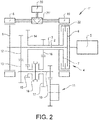
- Fig. 2 shows a variant of the transmission. With reference to Fig. 2 , only additional or modified components as compared to the transmission in Fig. 1 will be described.
- the transmission 1' has a further electric machine 19 mechanically connected to the second input shaft 3 for transmitting torque between the further electric machine 19 and the second input shaft 3.
- the further electric machine 19 is suitably directly connected to the second input shaft 3 such that the rotor of the further electric machine 8 is arranged on the second input shaft 3 or connected to a component which is arranged on the second input shaft 3.
- the rotor and the second input shaft 3 will rotate with same speed, these components could be arranged with a gear ratio between the rotor and the second input shaft.
- the further electric machine 19 is connected to the second input shaft separately from the engine 5.
- the further electric machine 19 can provide torque to the second input shaft 3 even if the engine 5 is disconnected from the second input shaft 3 by the clutch 4.
- the further electric machine 19 is arranged on a part 22 of the clutch 4 which part 22 rotates with the second output shaft 3.
- the further electric machine 19 is suitably a combined electric motor and generator, though in another embodiment the further electric machine could be an electric motor only.
- the further electric machine is suitably electrically connected to an energy storage device 20.
- the electric machine 8 and the further electric machine 19 can be electrically connected to each other for transferring energy between the machines.
- both the electric machine 8 and the further electric machine 19 are electrically connected to the energy storage device 20. Thereby, the electric machine 8 and the further electric machine 19 are electrically connected to each other.
- the electric machines 8, 19 can be AC motors/generators and then the electric machines are connected to an AC/DC inverter 21' which in turn is connected to the energy storage device 20, such as a battery.
- the inverter 21' can be used for converting AC to DC when charging the battery 20 by the generator function of the electric machine and/or the further electric machine, and for converting DC to AC when powering the electric machine 8 and/or the further electric machine 19 by the battery 20.
- the inverter 21' can be replaced by two separated inverters, one inverter for each electric machine.
- the electric machine 8 can have a rated power exceeding the rated power of the further electric machine 19, and suitably the electric machine 8 has a rated power exceeding 1.5 times the rated power of the further electric machine 19, and preferably the electric machine 8 has a rated power exceeding 2 times the rated power of the further electric machine 19.
Landscapes
- Engineering & Computer Science (AREA)
- Mechanical Engineering (AREA)
- Chemical & Material Sciences (AREA)
- Combustion & Propulsion (AREA)
- Transportation (AREA)
- General Engineering & Computer Science (AREA)
- Hybrid Electric Vehicles (AREA)
- Electric Propulsion And Braking For Vehicles (AREA)
Abstract
Description
- The invention relates to a transmission for a vehicle, which transmission comprises a first input shaft, a second input shaft and a clutch by which the first input shaft and the second input shaft are selectively connectable to an engine, and an electric machine connected to the first input shaft. The transmission further comprises an output shaft connected to a final drive.
- For a hybrid vehicle where an engine and one or more electric motors are connected to a gearbox for transmitting torque from the gearbox to wheels of the vehicle, a transmission with a gearbox and an electric motor can be designed in many ways for achieving the requisite gears and functions.
- There are however boundary conditions with respect to costs, weight and available space at the same time as it should be possible to use both the engine and the electric motor in an efficient way.
- An objective of the invention is to provide a transmission comprising an electric machine which transmission enables a more effective way of using power sources in a transmission for a vehicle.
- The objective is achieved by a transmission for a vehicle, wherein the transmission comprises a first input shaft, a second input shaft and a clutch by which the first input shaft and the second input shaft are selectively connectable to an engine, and an electric machine connected to the first input shaft, and wherein the transmission further comprises an output shaft connected to a final drive, and the first input shaft is permanently connected to the output shaft and the second input shaft is connectable to the output shaft.
- The invention is based on the insight that by such a transmission the electric machine can be used in a flexible manner at the same time as the losses on the transmission can be reduced.
- The power provided by the electric machine can be used in a way allowing the complexity of the mechanical components of the transmission to be reduced. The electric machine and the engine provide torque at different speeds, and gear ratios can be combined such that the number of gears can be reduced while providing the requisite torque over the entire speed interval.
- By having the first input shaft permanently connected to the output shaft, no coupling sleeve or synchronizer is needed. Hereby, losses and weight can be reduced. A reduced number of components will also reduce the need of lubrication. Further, by elimination of play associated with a synchronizer, a smoother transition between propelling and regeneration can be achieved.
- The electric machine can be an electric motor or a combined electric motor and generator. The clutch is suitably a so-called dual clutch used for achieving a dual clutch transmission (DCT). For example, the first input shaft and the second input shaft which are selectively connectable to an engine via the clutch can be arranged such that the first input shaft is an inner input shaft and the second input shaft is an outer input shaft, where the inner input shaft and the outer input shaft are arranged concentrically relative to each other.
- The electric machine is preferably directly connected to the first input shaft. In other words; the rotor of the electric machine is arranged on the first input shaft or connected to a component arranged on the first input shaft for providing torque. No coupling device is arranged which has to be closed for transferring torque to the first input shaft by the electric machine. Hereby, a design with relatively few components can be achieved. The rotor of the electric machine and the first input shaft can rotate with the same speed or a gear ratio can be arranged between the rotor and the first input shaft.
- By connection of the electric machine to the first input shaft separately from any engine connectable to the first input shaft via the clutch, the electric machine can be used for transferring torque even if the engine is disconnected.
- According to one embodiment, the transmission comprises a further electric machine connected to the second input shaft. The further electric machine can be used as a starter motor for the engine or generator driven by the engine at the same time as the electric machine connected to the first input shaft transfers torque to the output shaft. The further electric machine (and the engine) can also be used for transmitting torque to the output shaft. In addition, the further electric machine can be used for synchronizing the speeds of the second input shaft and the output shaft when shifting gears instead of synchronizing with a synchronizer resulting in heat losses.
- In the same way as described for the electric machine above, the further electric machine can be an electric motor or a combined electric motor and generator. The further electric machine is preferably directly connected to the second input shaft. In other words; the rotor of the further electric machine is arranged on the second input shaft or connected to a component arranged on the second input shaft for providing torque. No coupling device is arranged which has to be closed for transferring torque to the second input shaft by the further electric machine. Hereby, a design with relatively few components can be achieved. The rotor of the further electric machine and the second input shaft can rotate with the same speed or a gear ratio can be arranged between the rotor and the second input shaft.
- By connection of the further electric machine to the second input shaft separately from any engine connectable to the second input shaft via the clutch, the further electric machine can be used for transferring torque even if the engine is disconnected, for example during a pure electric drive mode.
- According to another embodiment, the first input shaft is connected to the output shaft through a gear wheel arranged on the first input shaft and a gear wheel arranged on the output shaft, the gear wheel of the first input shaft and the gear wheel of the output shaft being engaged with each other. Hereby, a first basic gear ratio is achieved for the transmission used when transmitting torque from the engine and/or from the electric machine, through the first input shaft and to the output shaft.
- According to a further embodiment, the second input shaft is connectable to the output shaft through a gear wheel arranged on the second input shaft and an idling gear wheel arranged on the output shaft, wherein the gear wheel of the second input shaft and the idling gear wheel of the output shaft are engaged with each other, and the idling gear wheel of the output shaft is rotationally lockable to the output shaft. Hereby, a gear ratio is achieved for the transmission used when transmitting torque from the engine, through the second input shaft and to the output shaft. In case of a further electric machine, this gear can also be used when torque is transmitted from the further electric machine, through the second input shaft and to the output shaft. By using an idling gear wheel, the gear can be deactivated, and another gear or neutral can be activated.
- Preferably, the second input shaft is connectable to the output shaft through a further gear wheel arranged on the second input shaft and a further idling gear wheel arranged on the output shaft, wherein the further gear wheel of the second input shaft and the further idling gear wheel of the output shaft are engaged with each other, and the further idling gear wheel of the output shaft is rotationally lockable to the output shaft.
- The transmission can comprise a coupling sleeve, wherein the idling gear wheel and the further idling gear wheel are selectively rotationally lockable to the output shaft by means of the coupling sleeve, and preferably the transmission comprises a synchronizer device comprising the coupling sleeve, wherein the synchronizer device is arranged to enable shifting between two gears and a neutral position.
- According to a further embodiment, the electric machine and the further electric machine are electrically connected to each other. By electrically connected to each other is meant that energy can be transferred between the electric machines which will increase the flexibility of the transmission. It should however be stressed that each electric machine is suitably independently controlled. The electric machine and/or the further electric machine is preferably electrically connected to an energy storage device. Hereby, energy can be transferred between the electric machines via the energy storage device and one or both electric machines can be used both as motor and generator. In case AC electric machines are used, each machine is suitably connected to the energy storage device by means of an inverter for converting AC to DC, when charging the energy storage device by the generator function of the machine, and from DC to AC, when powering the electric machine by the energy storage device.
- According to a further embodiment, the electric machine has a rated power exceeding the rated power of the further electric machine, and suitably the electric machine has a rated power exceeding 1.5 times the rated power of the further electric machine, and preferably the electric machine has a rated power exceeding 2 times the rated power of the further electric machine. Hereby, the electric machines can be optimized for managing the drive modes in a cost effective way. The electric machine (together with the further electric machine) can be dimensioned for covering all pure electric drive modes at the same time as the further electric machine is sufficient for generating power by means of the engine when driving at low speeds requiring torque but limited power. Generation of power during low speed enables such driving with use of one gear ratio only.
- Further advantages and advantageous features of the invention are disclosed in the following description and in the claims.
- With reference to the appended drawings, below follows a more detailed description of embodiments of the invention cited as examples.
- In the drawing:
-
Fig. 1 is a schematic view of one example embodiment of a transmission according to the invention, and -
Fig. 2 is a variant of the transmission inFig. 1 . -
Fig. 1 is a schematic view showing atransmission 1 for a vehicle. Thetransmission 1 comprises afirst input shaft 2, asecond input shaft 3 and aclutch 4 by which thefirst input shaft 2 and thesecond input shaft 3 are selectively connectable to anengine 5. Theengine 5 can be an internal combustion engine. Theclutch 4 can be a dual clutch having afirst clutch portion 6 for connecting thefirst input shaft 2 to theengine 5 and asecond clutch portion 7 for connecting thesecond input shaft 3 to theengine 5. Thefirst input shaft 2 can be an inner input shaft and thesecond input shaft 3 can be an outer input shaft, where theinner input shaft 2 and theouter input shaft 3 are arranged concentrically relative to each other with theouter input shaft 3 arranged outside of theinner input shaft 2. - The
transmission 1 comprises anelectric machine 8 mechanically connected to thefirst input shaft 2 for transmitting torque between theelectric machine 8 and thefirst input shaft 2. Theelectric machine 8 is suitably directly connected to thefirst input shaft 2 such that the rotor of theelectric machine 8 is arranged on thefirst input shaft 2 or connected to acomponent 9 which is arranged on thefirst input shaft 2. Although the rotor and thefirst input shaft 2 will rotate with same speed in the example embodiment illustrated inFig. 1 , these components could be arranged with a gear ratio between the rotor and the first input shaft. In the illustrated example embodiment inFig. 1 , theelectric machine 8 is connected to thefirst input shaft 2 separately from theengine 5. This means that theelectric machine 8 can provide torque to thefirst input shaft 2 even if theengine 5 is disconnected from thefirst input shaft 2 by theclutch 4. Theelectric machine 8 is suitably a combined electric motor and generator, though in another embodiment the electric machine could be an electric motor only. Theelectric machine 8 is suitably electrically connected to anenergy storage device 20. - The
electric machine 8 can be an AC motor/generator and then the electric machine is connected to an AC/DC inverter 21 which in turn is connected to theenergy storage device 20, such as a battery. Theinverter 21 can be used for converting AC to DC when charging thebattery 20 by the generator function of theelectric machine 8, and for converting DC to AC when powering theelectric machine 8 by thebattery 20. - The
transmission 1 further comprises anoutput shaft 10 connected to afinal drive 11. Thefirst input shaft 2 is permanently connected to theoutput shaft 10 and thesecond input shaft 3 is connectable to theoutput shaft 10. Thefirst input shaft 2 is connected to theoutput shaft 10 through agear wheel 12 arranged on thefirst input shaft 2 and agear wheel 13 arranged on theoutput shaft 10. Thegearwheel 12 of thefirst input shaft 2 and thegear wheel 13 of theoutput shaft 10 are engaged with each other for transferring torque to theoutput shaft 10 and further to thefinal drive 11. - The
second input shaft 3 is connectable to theoutput shaft 10 through agear wheel 14 arranged on thesecond input shaft 3 and anidling gear wheel 15 arranged on theoutput shaft 10. Thegear wheel 14 of thesecond input shaft 3 and theidling gear wheel 15 of theoutput shaft 10 are engaged with each other, and theidling gear wheel 15 of the output shaft is rotationally lockable to theoutput shaft 10, for transferring torque to theoutput shaft 10 and further to thefinal drive 11. Thesecond input shaft 3 is also connectable to theoutput shaft 10 through afurther gear wheel 16 arranged on thesecond input shaft 3 and a furtheridling gear wheel 17 arranged on theoutput shaft 10. Thefurther gear wheel 16 of thesecond input shaft 3 and the furtheridling gear wheel 17 of theoutput shaft 10 are engaged with each other, and the furtheridling gear wheel 17 of the output shaft is rotationally lockable to theoutput shaft 10, for transferring torque to theoutput shaft 10 and further to thefinal drive 11. - Further, the
transmission 1 suitably comprises acoupling sleeve 18. The idlinggearwheel 15 and the furtheridling gear wheel 17 are selectively rotationally lockable to theoutput shaft 10 by means of thecoupling sleeve 18. The transmission can comprise a synchronizer device comprising thecoupling sleeve 18, where the synchronizer device is arranged to enable shifting between a first gear provided by the first set ofgears gears Fig. 1 thecoupling sleeve 18 is illustrated in the neutral position. For achieving the first gear, thecoupling sleeve 18 is displaced to the left and for achieving the second gear, thecoupling sleeve 18 is displaced to the right. - Although in the illustrated example embodiment, the
second input shaft 3 can be selectively connected to theoutput shaft 10 by a first gear or second gear, of course in another embodiment of the transmission, the number of gears can be one or more depending on the application. -
Fig. 2 shows a variant of the transmission. With reference toFig. 2 , only additional or modified components as compared to the transmission inFig. 1 will be described. - In this example embodiment, the transmission 1' has a further
electric machine 19 mechanically connected to thesecond input shaft 3 for transmitting torque between the furtherelectric machine 19 and thesecond input shaft 3. The furtherelectric machine 19 is suitably directly connected to thesecond input shaft 3 such that the rotor of the furtherelectric machine 8 is arranged on thesecond input shaft 3 or connected to a component which is arranged on thesecond input shaft 3. Although, in the example embodiment illustrated inFig. 2 , the rotor and thesecond input shaft 3 will rotate with same speed, these components could be arranged with a gear ratio between the rotor and the second input shaft. In the illustrated example embodiment inFig. 2 , the furtherelectric machine 19 is connected to the second input shaft separately from theengine 5. This means that the furtherelectric machine 19 can provide torque to thesecond input shaft 3 even if theengine 5 is disconnected from thesecond input shaft 3 by theclutch 4. The furtherelectric machine 19 is arranged on apart 22 of the clutch 4 whichpart 22 rotates with thesecond output shaft 3. The furtherelectric machine 19 is suitably a combined electric motor and generator, though in another embodiment the further electric machine could be an electric motor only. The further electric machine is suitably electrically connected to anenergy storage device 20. - The
electric machine 8 and the furtherelectric machine 19 can be electrically connected to each other for transferring energy between the machines. In this example embodiment, both theelectric machine 8 and the furtherelectric machine 19 are electrically connected to theenergy storage device 20. Thereby, theelectric machine 8 and the furtherelectric machine 19 are electrically connected to each other. - The
electric machines energy storage device 20, such as a battery. The inverter 21' can be used for converting AC to DC when charging thebattery 20 by the generator function of the electric machine and/or the further electric machine, and for converting DC to AC when powering theelectric machine 8 and/or the furtherelectric machine 19 by thebattery 20. Optionally, the inverter 21' can be replaced by two separated inverters, one inverter for each electric machine. - The
electric machine 8 can have a rated power exceeding the rated power of the furtherelectric machine 19, and suitably theelectric machine 8 has a rated power exceeding 1.5 times the rated power of the furtherelectric machine 19, and preferably theelectric machine 8 has a rated power exceeding 2 times the rated power of the furtherelectric machine 19. - It is to be understood that the present invention is not limited to the embodiments described above and illustrated in the drawings; rather, the skilled person will recognize that many changes and modifications may be made within the scope of the appended claims.
Claims (15)
- A transmission (1) for a vehicle, the transmission comprising a first input shaft (2), a second input shaft (3) and a clutch (4) by which the first input shaft and the second input shaft are selectively connectable to an engine (5), and an electric machine (8) connected to the first input shaft (2), the transmission further comprising an output shaft (10) connected to a final drive (11), characterized in that the first input shaft (2) is permanently connected to the output shaft (10) and the second input shaft (3) is connectable to the output shaft (10).
- A transmission according to claim 1, characterized in that the first input shaft (2) is connected to the output shaft (10) through a gear wheel (12) arranged on the first input shaft and a gearwheel (13) arranged on the output shaft, the gearwheel (12) of the first input shaft and the gear wheel (13) of the output shaft being engaged with each other.
- A transmission according to claim 1 or 2, characterized in that the second input shaft (3) is connectable to the output shaft (10) through a gear wheel (14) arranged on the second input shaft and an idling gearwheel (15) arranged on the output shaft, the gear wheel (14) of the second input shaft and the idling gear wheel (15) of the output shaft being engaged with each other, and the idling gear wheel (15) of the output shaft being rotationally lockable to the output shaft (10).
- A transmission according to claim 3, characterized in that the second input shaft (3) is connectable to the output shaft (10) through a further gear wheel (16) arranged on the second input shaft and a further idling gear wheel (17) arranged on the output shaft, the further gear wheel (16) of the second input shaft and the further idling gear wheel (17) of the output shaft being engaged with each other, and the further idling gearwheel (17) of the output shaft being rotationally lockable to the output shaft (10).
- A transmission according to claim 4, characterized in that the transmission comprises a coupling sleeve (18), the idling gear wheel (15) and the further idling gear wheel (17) being selectively rotationally lockable to the output shaft by means of the coupling sleeve (18).
- A transmission according to claim 5, characterized in that the transmission comprises a synchronizer device comprising the coupling sleeve (18), the synchronizer device being arranged to enable shifting between two gears and a neutral position.
- A transmission according to any preceding claim, characterized in that the first input shaft (2) is an inner input shaft and the second input shaft (3) is an outer input shaft, the inner input shaft (2) and the outer input shaft (3) being arranged concentrically relative to each other.
- A transmission according to any preceding claim, characterized in that the electric machine (8) is directly connected to the first input shaft (2).
- A transmission according to any preceding claim, characterized in that the electric machine (8) is connected to the first input shaft (2) separately from any engine (5) connectable to the first input shaft (2) via the clutch (4).
- A transmission according to any preceding claim, characterized in that the electric machine (8) is electrically connected to an energy storage device (20).
- A transmission according to any preceding claim, characterized in that the transmission comprises a further electric machine (19) connected to the second input shaft (3).
- A transmission according to claim 11, characterized in that the further electric machine (19) is directly connected to the second input shaft (3).
- A transmission according to claim 11 or 12, characterized in that the further electric machine (19) is connected to the second input shaft (3) separately from any engine (5) connectable to the second input shaft (3) via the clutch (4).
- A transmission according to any of claims claim 11-13, characterized in that the electric machine (8) and the further electric machine (19) are electrically connected to each other.
- A transmission according to any of claims 11-14, characterized in that the electric machine (8) has a rated power exceeding the rated power of the further electric machine (19), preferably the electric machine (8) has a rated power exceeding 1.5 times the rated power of the further electric machine (19), and more preferably the electric machine (8) has a rated power exceeding 2 times the rated power of the further electric machine (19).
Priority Applications (4)
| Application Number | Priority Date | Filing Date | Title |
|---|---|---|---|
| EP18209170.2A EP3659844B1 (en) | 2018-11-29 | 2018-11-29 | A transmission for a vehicle |
| PCT/CN2019/111825 WO2020108162A1 (en) | 2018-11-29 | 2019-10-18 | A transmission for a vehicle |
| CN201980076116.4A CN113056627A (en) | 2018-11-29 | 2019-10-18 | Transmission device for vehicle |
| US17/327,678 US11890936B2 (en) | 2018-11-29 | 2021-05-22 | Transmission for a vehicle |
Applications Claiming Priority (1)
| Application Number | Priority Date | Filing Date | Title |
|---|---|---|---|
| EP18209170.2A EP3659844B1 (en) | 2018-11-29 | 2018-11-29 | A transmission for a vehicle |
Publications (2)
| Publication Number | Publication Date |
|---|---|
| EP3659844A1 true EP3659844A1 (en) | 2020-06-03 |
| EP3659844B1 EP3659844B1 (en) | 2022-05-04 |
Family
ID=64604443
Family Applications (1)
| Application Number | Title | Priority Date | Filing Date |
|---|---|---|---|
| EP18209170.2A Active EP3659844B1 (en) | 2018-11-29 | 2018-11-29 | A transmission for a vehicle |
Country Status (4)
| Country | Link |
|---|---|
| US (1) | US11890936B2 (en) |
| EP (1) | EP3659844B1 (en) |
| CN (1) | CN113056627A (en) |
| WO (1) | WO2020108162A1 (en) |
Cited By (2)
| Publication number | Priority date | Publication date | Assignee | Title |
|---|---|---|---|---|
| US20220212533A1 (en) * | 2019-03-14 | 2022-07-07 | Zf Friedrichshafen Ag | Hybrid Transmission Device and Motor Vehicle |
| DE102021200145A1 (en) | 2021-01-11 | 2022-07-14 | Zf Friedrichshafen Ag | Transmission arrangement, hybrid transmission arrangement, hybrid drive train and motor vehicle |
Citations (4)
| Publication number | Priority date | Publication date | Assignee | Title |
|---|---|---|---|---|
| DE102005048938A1 (en) * | 2005-10-13 | 2007-04-19 | Volkswagen Ag | Dual clutch transmission for a motor vehicle, in particular with a hybrid drive or method for controlling this dual clutch transmission |
| US20070175723A1 (en) * | 2005-12-21 | 2007-08-02 | Blessing Uli C | Dual clutch arrangement |
| US20120216638A1 (en) * | 2009-09-17 | 2012-08-30 | Borgwarner Inc. | Electric vehicle three speed dual clutch transmission |
| DE102013206176A1 (en) * | 2013-04-09 | 2014-10-09 | Magna Powertrain Ag & Co. Kg | vehicle drive |
Family Cites Families (15)
| Publication number | Priority date | Publication date | Assignee | Title |
|---|---|---|---|---|
| DE10165097B3 (en) * | 2000-07-18 | 2015-07-23 | Schaeffler Technologies AG & Co. KG | Double clutch |
| US7082850B2 (en) * | 2003-12-30 | 2006-08-01 | Eaton Corporation | Hybrid powertrain system |
| ITBO20090465A1 (en) * | 2009-07-21 | 2011-01-22 | Ferrari Spa | TRANSMISSION FOR A ROAD VEHICLE WITH HYBRID PROPULSION |
| DE102010008754B4 (en) * | 2010-02-15 | 2025-02-06 | Dr. Ing. H.C. F. Porsche Aktiengesellschaft | drive system, in particular for a motor vehicle |
| CN102691770B (en) * | 2012-05-29 | 2015-07-15 | 浙江吉利汽车研究院有限公司杭州分公司 | Double-clutch transmission for hybrid power |
| CN202896270U (en) * | 2012-09-18 | 2013-04-24 | 中国第一汽车股份有限公司 | Extend range type electric vehicle power system utilizing double-clutch two-gear transmission |
| KR101481304B1 (en) * | 2013-08-09 | 2015-01-09 | 현대자동차주식회사 | Hybrid powertrain used double clutch transmission |
| CN203543640U (en) * | 2013-10-16 | 2014-04-16 | 浙江吉利控股集团有限公司 | Hybrid power system based on dual-clutch automatic transmission and vehicle |
| KR101500203B1 (en) * | 2013-11-25 | 2015-03-06 | 현대자동차주식회사 | Dct hybrid power tranin |
| US10670123B2 (en) * | 2014-01-30 | 2020-06-02 | Byd Company Limited | Power transmission system for vehicle and vehicle comprising the same |
| GB2522706B (en) * | 2014-02-04 | 2017-07-12 | Jaguar Land Rover Ltd | Dual clutch transmission for a vehicle, with electric generator and/or motor |
| CN105082972A (en) * | 2014-04-18 | 2015-11-25 | 比亚迪股份有限公司 | Power transmission system and vehicle with same |
| CN106143112B (en) * | 2015-03-23 | 2018-11-06 | 比亚迪股份有限公司 | Power drive system and vehicle with it |
| CN107650664A (en) * | 2017-09-08 | 2018-02-02 | 东风汽车公司 | A kind of multi-mode hybrid transmission device with double clutch |
| CN207809033U (en) * | 2017-12-29 | 2018-09-04 | 比亚迪股份有限公司 | Hybrid electric drive system and vehicle |
-
2018
- 2018-11-29 EP EP18209170.2A patent/EP3659844B1/en active Active
-
2019
- 2019-10-18 WO PCT/CN2019/111825 patent/WO2020108162A1/en not_active Ceased
- 2019-10-18 CN CN201980076116.4A patent/CN113056627A/en active Pending
-
2021
- 2021-05-22 US US17/327,678 patent/US11890936B2/en active Active
Patent Citations (4)
| Publication number | Priority date | Publication date | Assignee | Title |
|---|---|---|---|---|
| DE102005048938A1 (en) * | 2005-10-13 | 2007-04-19 | Volkswagen Ag | Dual clutch transmission for a motor vehicle, in particular with a hybrid drive or method for controlling this dual clutch transmission |
| US20070175723A1 (en) * | 2005-12-21 | 2007-08-02 | Blessing Uli C | Dual clutch arrangement |
| US20120216638A1 (en) * | 2009-09-17 | 2012-08-30 | Borgwarner Inc. | Electric vehicle three speed dual clutch transmission |
| DE102013206176A1 (en) * | 2013-04-09 | 2014-10-09 | Magna Powertrain Ag & Co. Kg | vehicle drive |
Cited By (2)
| Publication number | Priority date | Publication date | Assignee | Title |
|---|---|---|---|---|
| US20220212533A1 (en) * | 2019-03-14 | 2022-07-07 | Zf Friedrichshafen Ag | Hybrid Transmission Device and Motor Vehicle |
| DE102021200145A1 (en) | 2021-01-11 | 2022-07-14 | Zf Friedrichshafen Ag | Transmission arrangement, hybrid transmission arrangement, hybrid drive train and motor vehicle |
Also Published As
| Publication number | Publication date |
|---|---|
| US20210276406A1 (en) | 2021-09-09 |
| EP3659844B1 (en) | 2022-05-04 |
| WO2020108162A1 (en) | 2020-06-04 |
| US11890936B2 (en) | 2024-02-06 |
| CN113056627A (en) | 2021-06-29 |
Similar Documents
| Publication | Publication Date | Title |
|---|---|---|
| CN104340046B (en) | Vehicle powertrain with clutch actuator providing electrical power | |
| CN106696676B (en) | Powertrain comprising a modular transmission unit | |
| US10183569B2 (en) | Power generation control device for hybrid vehicle | |
| RU2653723C2 (en) | Method of management of a hybrid power transmission for optimization of fuel consumption, vehicle and electronic device for hybrid power transmission control | |
| CN102348568B (en) | Power transmitting device for hybrid vehicle | |
| US6416437B2 (en) | Transmission for hybrid electric vehicle | |
| CN112166046B (en) | Hybrid transmission and hybrid vehicle | |
| US10017040B2 (en) | Drive unit for a hybrid vehicle | |
| WO2019218266A1 (en) | Hybrid power transmission and vehicle | |
| CN102307744B (en) | Power transmitting device | |
| KR101637725B1 (en) | Transmission for hybrid vehicle | |
| RU2653332C2 (en) | Method of management of a hybrid power transmission for transfer switching without torque moment interruption, vehicle and electronic device for hybrid power transmission control | |
| US20170355258A1 (en) | Hybrid Power System | |
| RU2655233C2 (en) | Method of management of a hybrid power transmission, vehicle and electronic device for hybrid power transmission control | |
| US11890936B2 (en) | Transmission for a vehicle | |
| CN105658464A (en) | Power system and method of operation for a motor vehicle | |
| CN108397521A (en) | hybrid transmission and vehicle | |
| CN209141888U (en) | Speed changer and dynamical system for hybrid vehicle | |
| US11565702B2 (en) | Method for operating a hybrid powertrain | |
| WO2020125507A1 (en) | A transmission for a vehicle | |
| WO2023133759A1 (en) | Hybrid power system, and vehicle | |
| KR101592636B1 (en) | Hybrid power train for vehicle | |
| US12024022B2 (en) | Hybrid powertrain for a vehicle | |
| CN104653725B (en) | transmission | |
| US10336177B2 (en) | Drive device and method of operating a drive device |
Legal Events
| Date | Code | Title | Description |
|---|---|---|---|
| PUAI | Public reference made under article 153(3) epc to a published international application that has entered the european phase |
Free format text: ORIGINAL CODE: 0009012 |
|
| STAA | Information on the status of an ep patent application or granted ep patent |
Free format text: STATUS: REQUEST FOR EXAMINATION WAS MADE |
|
| 17P | Request for examination filed |
Effective date: 20181129 |
|
| AK | Designated contracting states |
Kind code of ref document: A1 Designated state(s): AL AT BE BG CH CY CZ DE DK EE ES FI FR GB GR HR HU IE IS IT LI LT LU LV MC MK MT NL NO PL PT RO RS SE SI SK SM TR |
|
| AX | Request for extension of the european patent |
Extension state: BA ME |
|
| GRAP | Despatch of communication of intention to grant a patent |
Free format text: ORIGINAL CODE: EPIDOSNIGR1 |
|
| STAA | Information on the status of an ep patent application or granted ep patent |
Free format text: STATUS: GRANT OF PATENT IS INTENDED |
|
| INTG | Intention to grant announced |
Effective date: 20211223 |
|
| GRAS | Grant fee paid |
Free format text: ORIGINAL CODE: EPIDOSNIGR3 |
|
| GRAA | (expected) grant |
Free format text: ORIGINAL CODE: 0009210 |
|
| STAA | Information on the status of an ep patent application or granted ep patent |
Free format text: STATUS: THE PATENT HAS BEEN GRANTED |
|
| AK | Designated contracting states |
Kind code of ref document: B1 Designated state(s): AL AT BE BG CH CY CZ DE DK EE ES FI FR GB GR HR HU IE IS IT LI LT LU LV MC MK MT NL NO PL PT RO RS SE SI SK SM TR |
|
| REG | Reference to a national code |
Ref country code: GB Ref legal event code: FG4D |
|
| REG | Reference to a national code |
Ref country code: CH Ref legal event code: EP |
|
| REG | Reference to a national code |
Ref country code: AT Ref legal event code: REF Ref document number: 1488679 Country of ref document: AT Kind code of ref document: T Effective date: 20220515 |
|
| REG | Reference to a national code |
Ref country code: IE Ref legal event code: FG4D Ref country code: DE Ref legal event code: R096 Ref document number: 602018034848 Country of ref document: DE |
|
| REG | Reference to a national code |
Ref country code: LT Ref legal event code: MG9D |
|
| REG | Reference to a national code |
Ref country code: NL Ref legal event code: MP Effective date: 20220504 |
|
| REG | Reference to a national code |
Ref country code: AT Ref legal event code: MK05 Ref document number: 1488679 Country of ref document: AT Kind code of ref document: T Effective date: 20220504 |
|
| PG25 | Lapsed in a contracting state [announced via postgrant information from national office to epo] |
Ref country code: SE Free format text: LAPSE BECAUSE OF FAILURE TO SUBMIT A TRANSLATION OF THE DESCRIPTION OR TO PAY THE FEE WITHIN THE PRESCRIBED TIME-LIMIT Effective date: 20220504 Ref country code: PT Free format text: LAPSE BECAUSE OF FAILURE TO SUBMIT A TRANSLATION OF THE DESCRIPTION OR TO PAY THE FEE WITHIN THE PRESCRIBED TIME-LIMIT Effective date: 20220905 Ref country code: NO Free format text: LAPSE BECAUSE OF FAILURE TO SUBMIT A TRANSLATION OF THE DESCRIPTION OR TO PAY THE FEE WITHIN THE PRESCRIBED TIME-LIMIT Effective date: 20220804 Ref country code: NL Free format text: LAPSE BECAUSE OF FAILURE TO SUBMIT A TRANSLATION OF THE DESCRIPTION OR TO PAY THE FEE WITHIN THE PRESCRIBED TIME-LIMIT Effective date: 20220504 Ref country code: LT Free format text: LAPSE BECAUSE OF FAILURE TO SUBMIT A TRANSLATION OF THE DESCRIPTION OR TO PAY THE FEE WITHIN THE PRESCRIBED TIME-LIMIT Effective date: 20220504 Ref country code: HR Free format text: LAPSE BECAUSE OF FAILURE TO SUBMIT A TRANSLATION OF THE DESCRIPTION OR TO PAY THE FEE WITHIN THE PRESCRIBED TIME-LIMIT Effective date: 20220504 Ref country code: FI Free format text: LAPSE BECAUSE OF FAILURE TO SUBMIT A TRANSLATION OF THE DESCRIPTION OR TO PAY THE FEE WITHIN THE PRESCRIBED TIME-LIMIT Effective date: 20220504 Ref country code: ES Free format text: LAPSE BECAUSE OF FAILURE TO SUBMIT A TRANSLATION OF THE DESCRIPTION OR TO PAY THE FEE WITHIN THE PRESCRIBED TIME-LIMIT Effective date: 20220504 Ref country code: BG Free format text: LAPSE BECAUSE OF FAILURE TO SUBMIT A TRANSLATION OF THE DESCRIPTION OR TO PAY THE FEE WITHIN THE PRESCRIBED TIME-LIMIT Effective date: 20220804 Ref country code: AT Free format text: LAPSE BECAUSE OF FAILURE TO SUBMIT A TRANSLATION OF THE DESCRIPTION OR TO PAY THE FEE WITHIN THE PRESCRIBED TIME-LIMIT Effective date: 20220504 |
|
| PG25 | Lapsed in a contracting state [announced via postgrant information from national office to epo] |
Ref country code: RS Free format text: LAPSE BECAUSE OF FAILURE TO SUBMIT A TRANSLATION OF THE DESCRIPTION OR TO PAY THE FEE WITHIN THE PRESCRIBED TIME-LIMIT Effective date: 20220504 Ref country code: PL Free format text: LAPSE BECAUSE OF FAILURE TO SUBMIT A TRANSLATION OF THE DESCRIPTION OR TO PAY THE FEE WITHIN THE PRESCRIBED TIME-LIMIT Effective date: 20220504 Ref country code: LV Free format text: LAPSE BECAUSE OF FAILURE TO SUBMIT A TRANSLATION OF THE DESCRIPTION OR TO PAY THE FEE WITHIN THE PRESCRIBED TIME-LIMIT Effective date: 20220504 Ref country code: IS Free format text: LAPSE BECAUSE OF FAILURE TO SUBMIT A TRANSLATION OF THE DESCRIPTION OR TO PAY THE FEE WITHIN THE PRESCRIBED TIME-LIMIT Effective date: 20220904 |
|
| PG25 | Lapsed in a contracting state [announced via postgrant information from national office to epo] |
Ref country code: SM Free format text: LAPSE BECAUSE OF FAILURE TO SUBMIT A TRANSLATION OF THE DESCRIPTION OR TO PAY THE FEE WITHIN THE PRESCRIBED TIME-LIMIT Effective date: 20220504 Ref country code: SK Free format text: LAPSE BECAUSE OF FAILURE TO SUBMIT A TRANSLATION OF THE DESCRIPTION OR TO PAY THE FEE WITHIN THE PRESCRIBED TIME-LIMIT Effective date: 20220504 Ref country code: RO Free format text: LAPSE BECAUSE OF FAILURE TO SUBMIT A TRANSLATION OF THE DESCRIPTION OR TO PAY THE FEE WITHIN THE PRESCRIBED TIME-LIMIT Effective date: 20220504 Ref country code: EE Free format text: LAPSE BECAUSE OF FAILURE TO SUBMIT A TRANSLATION OF THE DESCRIPTION OR TO PAY THE FEE WITHIN THE PRESCRIBED TIME-LIMIT Effective date: 20220504 Ref country code: DK Free format text: LAPSE BECAUSE OF FAILURE TO SUBMIT A TRANSLATION OF THE DESCRIPTION OR TO PAY THE FEE WITHIN THE PRESCRIBED TIME-LIMIT Effective date: 20220504 Ref country code: CZ Free format text: LAPSE BECAUSE OF FAILURE TO SUBMIT A TRANSLATION OF THE DESCRIPTION OR TO PAY THE FEE WITHIN THE PRESCRIBED TIME-LIMIT Effective date: 20220504 |
|
| REG | Reference to a national code |
Ref country code: DE Ref legal event code: R097 Ref document number: 602018034848 Country of ref document: DE |
|
| PLBE | No opposition filed within time limit |
Free format text: ORIGINAL CODE: 0009261 |
|
| STAA | Information on the status of an ep patent application or granted ep patent |
Free format text: STATUS: NO OPPOSITION FILED WITHIN TIME LIMIT |
|
| PG25 | Lapsed in a contracting state [announced via postgrant information from national office to epo] |
Ref country code: AL Free format text: LAPSE BECAUSE OF FAILURE TO SUBMIT A TRANSLATION OF THE DESCRIPTION OR TO PAY THE FEE WITHIN THE PRESCRIBED TIME-LIMIT Effective date: 20220504 |
|
| 26N | No opposition filed |
Effective date: 20230207 |
|
| PG25 | Lapsed in a contracting state [announced via postgrant information from national office to epo] |
Ref country code: SI Free format text: LAPSE BECAUSE OF FAILURE TO SUBMIT A TRANSLATION OF THE DESCRIPTION OR TO PAY THE FEE WITHIN THE PRESCRIBED TIME-LIMIT Effective date: 20220504 |
|
| PG25 | Lapsed in a contracting state [announced via postgrant information from national office to epo] |
Ref country code: MC Free format text: LAPSE BECAUSE OF FAILURE TO SUBMIT A TRANSLATION OF THE DESCRIPTION OR TO PAY THE FEE WITHIN THE PRESCRIBED TIME-LIMIT Effective date: 20220504 |
|
| REG | Reference to a national code |
Ref country code: CH Ref legal event code: PL |
|
| REG | Reference to a national code |
Ref country code: BE Ref legal event code: MM Effective date: 20221130 |
|
| PG25 | Lapsed in a contracting state [announced via postgrant information from national office to epo] |
Ref country code: LI Free format text: LAPSE BECAUSE OF NON-PAYMENT OF DUE FEES Effective date: 20221130 Ref country code: CH Free format text: LAPSE BECAUSE OF NON-PAYMENT OF DUE FEES Effective date: 20221130 |
|
| PG25 | Lapsed in a contracting state [announced via postgrant information from national office to epo] |
Ref country code: LU Free format text: LAPSE BECAUSE OF NON-PAYMENT OF DUE FEES Effective date: 20221129 |
|
| PG25 | Lapsed in a contracting state [announced via postgrant information from national office to epo] |
Ref country code: IE Free format text: LAPSE BECAUSE OF NON-PAYMENT OF DUE FEES Effective date: 20221129 |
|
| PG25 | Lapsed in a contracting state [announced via postgrant information from national office to epo] |
Ref country code: BE Free format text: LAPSE BECAUSE OF NON-PAYMENT OF DUE FEES Effective date: 20221130 |
|
| PG25 | Lapsed in a contracting state [announced via postgrant information from national office to epo] |
Ref country code: IT Free format text: LAPSE BECAUSE OF FAILURE TO SUBMIT A TRANSLATION OF THE DESCRIPTION OR TO PAY THE FEE WITHIN THE PRESCRIBED TIME-LIMIT Effective date: 20220504 |
|
| PG25 | Lapsed in a contracting state [announced via postgrant information from national office to epo] |
Ref country code: HU Free format text: LAPSE BECAUSE OF FAILURE TO SUBMIT A TRANSLATION OF THE DESCRIPTION OR TO PAY THE FEE WITHIN THE PRESCRIBED TIME-LIMIT; INVALID AB INITIO Effective date: 20181129 |
|
| PG25 | Lapsed in a contracting state [announced via postgrant information from national office to epo] |
Ref country code: CY Free format text: LAPSE BECAUSE OF FAILURE TO SUBMIT A TRANSLATION OF THE DESCRIPTION OR TO PAY THE FEE WITHIN THE PRESCRIBED TIME-LIMIT Effective date: 20220504 |
|
| PG25 | Lapsed in a contracting state [announced via postgrant information from national office to epo] |
Ref country code: MK Free format text: LAPSE BECAUSE OF FAILURE TO SUBMIT A TRANSLATION OF THE DESCRIPTION OR TO PAY THE FEE WITHIN THE PRESCRIBED TIME-LIMIT Effective date: 20220504 |
|
| PG25 | Lapsed in a contracting state [announced via postgrant information from national office to epo] |
Ref country code: TR Free format text: LAPSE BECAUSE OF FAILURE TO SUBMIT A TRANSLATION OF THE DESCRIPTION OR TO PAY THE FEE WITHIN THE PRESCRIBED TIME-LIMIT Effective date: 20220504 |
|
| PG25 | Lapsed in a contracting state [announced via postgrant information from national office to epo] |
Ref country code: MT Free format text: LAPSE BECAUSE OF FAILURE TO SUBMIT A TRANSLATION OF THE DESCRIPTION OR TO PAY THE FEE WITHIN THE PRESCRIBED TIME-LIMIT Effective date: 20220504 |
|
| PG25 | Lapsed in a contracting state [announced via postgrant information from national office to epo] |
Ref country code: BG Free format text: LAPSE BECAUSE OF FAILURE TO SUBMIT A TRANSLATION OF THE DESCRIPTION OR TO PAY THE FEE WITHIN THE PRESCRIBED TIME-LIMIT Effective date: 20220504 |
|
| PG25 | Lapsed in a contracting state [announced via postgrant information from national office to epo] |
Ref country code: BG Free format text: LAPSE BECAUSE OF FAILURE TO SUBMIT A TRANSLATION OF THE DESCRIPTION OR TO PAY THE FEE WITHIN THE PRESCRIBED TIME-LIMIT Effective date: 20220504 |
|
| PG25 | Lapsed in a contracting state [announced via postgrant information from national office to epo] |
Ref country code: GR Free format text: LAPSE BECAUSE OF NON-PAYMENT OF DUE FEES Effective date: 20220504 |
|
| PG25 | Lapsed in a contracting state [announced via postgrant information from national office to epo] |
Ref country code: GR Free format text: LAPSE BECAUSE OF NON-PAYMENT OF DUE FEES Effective date: 20220504 |
|
| PGFP | Annual fee paid to national office [announced via postgrant information from national office to epo] |
Ref country code: DE Payment date: 20251118 Year of fee payment: 8 |
|
| PGFP | Annual fee paid to national office [announced via postgrant information from national office to epo] |
Ref country code: GB Payment date: 20251020 Year of fee payment: 8 |
|
| PGFP | Annual fee paid to national office [announced via postgrant information from national office to epo] |
Ref country code: FR Payment date: 20251020 Year of fee payment: 8 |