EP3659745B1 - Electrically actuated clamp device - Google Patents
Electrically actuated clamp device Download PDFInfo
- Publication number
- EP3659745B1 EP3659745B1 EP18872495.9A EP18872495A EP3659745B1 EP 3659745 B1 EP3659745 B1 EP 3659745B1 EP 18872495 A EP18872495 A EP 18872495A EP 3659745 B1 EP3659745 B1 EP 3659745B1
- Authority
- EP
- European Patent Office
- Prior art keywords
- output rod
- main body
- rod main
- lock
- power transmission
- Prior art date
- Legal status (The legal status is an assumption and is not a legal conclusion. Google has not performed a legal analysis and makes no representation as to the accuracy of the status listed.)
- Active
Links
Images




Classifications
-
- B—PERFORMING OPERATIONS; TRANSPORTING
- B23—MACHINE TOOLS; METAL-WORKING NOT OTHERWISE PROVIDED FOR
- B23Q—DETAILS, COMPONENTS, OR ACCESSORIES FOR MACHINE TOOLS, e.g. ARRANGEMENTS FOR COPYING OR CONTROLLING; MACHINE TOOLS IN GENERAL CHARACTERISED BY THE CONSTRUCTION OF PARTICULAR DETAILS OR COMPONENTS; COMBINATIONS OR ASSOCIATIONS OF METAL-WORKING MACHINES, NOT DIRECTED TO A PARTICULAR RESULT
- B23Q3/00—Devices holding, supporting, or positioning work or tools, of a kind normally removable from the machine
- B23Q3/02—Devices holding, supporting, or positioning work or tools, of a kind normally removable from the machine for mounting on a work-table, tool-slide, or analogous part
- B23Q3/06—Work-clamping means
- B23Q3/062—Work-clamping means adapted for holding workpieces having a special form or being made from a special material
-
- B—PERFORMING OPERATIONS; TRANSPORTING
- B25—HAND TOOLS; PORTABLE POWER-DRIVEN TOOLS; MANIPULATORS
- B25B—TOOLS OR BENCH DEVICES NOT OTHERWISE PROVIDED FOR, FOR FASTENING, CONNECTING, DISENGAGING, OR HOLDING
- B25B5/00—Clamps
- B25B5/06—Arrangements for positively actuating jaws
- B25B5/10—Arrangements for positively actuating jaws using screws
-
- B—PERFORMING OPERATIONS; TRANSPORTING
- B23—MACHINE TOOLS; METAL-WORKING NOT OTHERWISE PROVIDED FOR
- B23Q—DETAILS, COMPONENTS, OR ACCESSORIES FOR MACHINE TOOLS, e.g. ARRANGEMENTS FOR COPYING OR CONTROLLING; MACHINE TOOLS IN GENERAL CHARACTERISED BY THE CONSTRUCTION OF PARTICULAR DETAILS OR COMPONENTS; COMBINATIONS OR ASSOCIATIONS OF METAL-WORKING MACHINES, NOT DIRECTED TO A PARTICULAR RESULT
- B23Q3/00—Devices holding, supporting, or positioning work or tools, of a kind normally removable from the machine
- B23Q3/02—Devices holding, supporting, or positioning work or tools, of a kind normally removable from the machine for mounting on a work-table, tool-slide, or analogous part
- B23Q3/06—Work-clamping means
-
- B—PERFORMING OPERATIONS; TRANSPORTING
- B23—MACHINE TOOLS; METAL-WORKING NOT OTHERWISE PROVIDED FOR
- B23Q—DETAILS, COMPONENTS, OR ACCESSORIES FOR MACHINE TOOLS, e.g. ARRANGEMENTS FOR COPYING OR CONTROLLING; MACHINE TOOLS IN GENERAL CHARACTERISED BY THE CONSTRUCTION OF PARTICULAR DETAILS OR COMPONENTS; COMBINATIONS OR ASSOCIATIONS OF METAL-WORKING MACHINES, NOT DIRECTED TO A PARTICULAR RESULT
- B23Q3/00—Devices holding, supporting, or positioning work or tools, of a kind normally removable from the machine
- B23Q3/02—Devices holding, supporting, or positioning work or tools, of a kind normally removable from the machine for mounting on a work-table, tool-slide, or analogous part
- B23Q3/06—Work-clamping means
- B23Q3/069—Work-clamping means for pressing workpieces against a work-table
-
- B—PERFORMING OPERATIONS; TRANSPORTING
- B25—HAND TOOLS; PORTABLE POWER-DRIVEN TOOLS; MANIPULATORS
- B25B—TOOLS OR BENCH DEVICES NOT OTHERWISE PROVIDED FOR, FOR FASTENING, CONNECTING, DISENGAGING, OR HOLDING
- B25B5/00—Clamps
- B25B5/06—Arrangements for positively actuating jaws
- B25B5/061—Arrangements for positively actuating jaws with fluid drive
- B25B5/062—Arrangements for positively actuating jaws with fluid drive with clamping means pivoting around an axis parallel to the pressing direction
-
- B—PERFORMING OPERATIONS; TRANSPORTING
- B25—HAND TOOLS; PORTABLE POWER-DRIVEN TOOLS; MANIPULATORS
- B25B—TOOLS OR BENCH DEVICES NOT OTHERWISE PROVIDED FOR, FOR FASTENING, CONNECTING, DISENGAGING, OR HOLDING
- B25B5/00—Clamps
- B25B5/16—Details, e.g. jaws, jaw attachments
-
- B—PERFORMING OPERATIONS; TRANSPORTING
- B23—MACHINE TOOLS; METAL-WORKING NOT OTHERWISE PROVIDED FOR
- B23Q—DETAILS, COMPONENTS, OR ACCESSORIES FOR MACHINE TOOLS, e.g. ARRANGEMENTS FOR COPYING OR CONTROLLING; MACHINE TOOLS IN GENERAL CHARACTERISED BY THE CONSTRUCTION OF PARTICULAR DETAILS OR COMPONENTS; COMBINATIONS OR ASSOCIATIONS OF METAL-WORKING MACHINES, NOT DIRECTED TO A PARTICULAR RESULT
- B23Q2703/00—Work clamping
- B23Q2703/02—Work clamping means
-
- B—PERFORMING OPERATIONS; TRANSPORTING
- B23—MACHINE TOOLS; METAL-WORKING NOT OTHERWISE PROVIDED FOR
- B23Q—DETAILS, COMPONENTS, OR ACCESSORIES FOR MACHINE TOOLS, e.g. ARRANGEMENTS FOR COPYING OR CONTROLLING; MACHINE TOOLS IN GENERAL CHARACTERISED BY THE CONSTRUCTION OF PARTICULAR DETAILS OR COMPONENTS; COMBINATIONS OR ASSOCIATIONS OF METAL-WORKING MACHINES, NOT DIRECTED TO A PARTICULAR RESULT
- B23Q2703/00—Work clamping
- B23Q2703/12—Accessories for attaching
Definitions
- the present invention relates to an electric clamping device.
- a decelerator is disposed below an output rod.
- a conversion mechanism configured to convert rotational motion of a motor connected to the decelerator to linear motion and to transmit the linear motion to the output rod is provided between the output rod and the decelerator. This arrangement forms a basic structure of an electric clamping device in which upward/downward movement of its output rod is driven by a motor.
- Patent Literature 1 Japanese Unexamined Patent Publication No. 2014-223714
- DE 39 12 308 C1 discloses an electric clamping device comprising: an output rod inserted in a housing so as to be movable in an axial direction toward a lock side and a release side; a motor attached to the housing; and a decelerator, wherein the output rod comprises: a cylindrical power transmission member screw-connected to the decelerator; the output rod can also rotate between the locking and the releasing position.
- An object of the present invention is to mitigate the problem: a decrease in efficiency of transmission between an output rod and a decelerator in an electric clamping device in which the decelerator is disposed beside the output rod.
- an electric clamping device is structured as follows, as shown in FIG. 1 to FIG. 6 , for example.
- the electric clamping device in an aspect of the present invention includes: an output rod 20 inserted in a housing 1 so as to be movable in an axial direction toward a lock side and a release side; a motor 5 attached to the housing 1; and a decelerator 6 provided beside the output rod 20, the decelerator 6 configured to transmit rotational motion of the motor 5 to the output rod 20.
- the output rod 20 includes: a tubular power transmission member 25 screw-connected to the decelerator 6; an output rod main body 24 disposed radially inward of an inner peripheral surface of a cylindrical hole of the power transmission member 25 with a clearance between the output rod main body 24 and the inner peripheral surface; a rotation preventing mechanism 26 configured to prevent relative rotation between the output rod main body 24 and the power transmission member 25; a lock-side driving mechanism 27, 42 configured to move the output rod main body 24 toward the lock side via the power transmission member 25; a release-side driving mechanism 28 configured to move the output rod main body 24 toward the release side via the power transmission member 25; and an output rod guide mechanism 29 configured to guide movement of the output rod main body 24 while preventing co-rotation with the decelerator 6.
- the electric clamping device of the above aspect of the present invention provides the following functions and effects.
- the power transmission member structuring the output rod is provided as a separate member not unitary with the output rod main body, and the power transmission member is disposed radially outward from the output rod main body with the clearance between them. Therefore, the power transmission member is less likely to be affected by the reaction force from the object, unlike the output rod main body.
- the electric clamping device of the above aspect of the present invention further includes the following features.
- the lock-side driving mechanism 27, 42 includes: a transmission surface 31a, 43a provided at a release-side portion of a flange portion 31 provided on an outer periphery of the output rod main body 24, the transmission surface 31a, 43a sloping toward the lock side relative to the axial direction; and a push surface 32a provided on a lock-side inner surface of the power transmission member 25, and that when the motor 5 moves the power transmission member 25 to the lock side via the decelerator 6, the push surface 32a pushes the transmission surface 31a, 43a thereby to move the output rod main body 24 toward the lock side.
- the above arrangement makes it possible to stabilize the motion of the output rod main body inclined by the reaction force, i.e., swaying motion of the output rod main body. This further mitigates the effect of the reaction force to the power transmission member structuring the output rod.
- the electric clamping device of the above aspect of the present invention is arranged such that the transmission surface 31a, 43a is shaped as a spherical surface. This arrangement further stabilizes the swaying motion of the output rod main body.
- the electric clamping device of the above aspect of the present invention is arranged such that the spherical push surface 32a is shaped as a spherical surface configured to make surface contact with the transmission surface 31a, 43a. This arrangement further stabilizes the swaying motion of the output rod main body.
- the electric clamping device of the above aspect of the present invention is arranged such that the transmission surface 43a is structured by a plurality of transmission balls 43 fitted in a recessed portion 31b provided on a release-side surface of the flange portion 31. This arrangement further stabilizes the swaying motion of the output rod main body.
- the electric clamping device of the above aspect of the present invention is arranged such that guide cylinders 40, 41 configured to guide movement of the output rod main body 24 in the axial direction are respectively attached to a release-side end portion and a lock-side end portion of the housing 1.
- This arrangement makes the amount of sway of the output rod main body smaller.
- the electric clamping device of the above aspect of the present invention is arranged such that: an annular wall 34 protrudes from a lock-side inner surface of the housing 1 toward the release side; the output rod main body 24 is inserted in the annular wall 34; the output rod guide mechanism 29 includes a plurality of guide grooves 35 provided on an outer periphery of the output rod main body 24 at predetermined intervals in its circumferential direction and engagement balls 38 supported by the annular wall 34, the engagement balls 38 respectively fitted in the guide grooves 35; and each of the guide grooves 35 includes a rotation groove 36 and a linear groove 37 which are provided continuously from the lock side toward the release side.
- This arrangement realizes the type of electric clamping device in which an output rod (output rod main body) rotates.
- the decelerator 6 is a worm decelerator.
- a housing 1 includes a lower housing 2 and an upper housing 3.
- a motor 5 is attached to a side surface of the upper housing 3 via a joint member 4.
- a decelerator 6 is attached in the upper housing 3.
- the lower housing 2 is fixed to a table T functioning as a stationary stand by a plurality of bolts (not shown).
- the motor 5 in this embodiment is a stepping motor.
- the decelerator 6 in this embodiment is a worm decelerator.
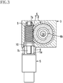
- the worm decelerator includes: a cylindrical worm 7 connected to an output shaft 5a of the motor 5; and a worm wheel 8 meshing with the worm 7.
- shafts 7a and 7b provided at both axial end portions of the worm 7 are respectively supported by bearings 9 and 10 in a rotatable manner, and this allows the worm 7 to be rotatable.
- a tubular joint member 11 is fixed, for example, by press-fitting, to an axial end portion 8a of the worm wheel 8.
- the worm wheel 8 to which the joint member 11 is fixed is supported by bearings 12 and 13 in a rotatable manner.
- An output rod 20 is inserted in the housing 1 (the upper housing 3 and the lower housing 2) so as to be movable in an up-down direction (axial direction) toward a release side (upper side) and toward a lock side (lower side).
- a cap 21 is attached to a lower end portion of the lower housing 2, and thereby the housing 1 is sealed.
- the output rod 20 includes: an output rod main body 24; and a tubular power transmission member 25 in which the output rod main body 24 is inserted.
- a clamp arm 22 is fixed to an upper end portion of the output rod main body 24 by a nut 23.
- the output rod main body 24 is disposed radially inward of an inner peripheral surface of a cylindrical hole of the power transmission member 25 with a clearance between them. The clearance is very small.
- a guide cylinder 40 configured to guide movement of the output rod main body 24 in the axial direction is attached to an upper portion (release-side end portion) of the upper housing 3.
- a guide cylinder 41 configured to guide movement of the output rod main body 24 in the axial direction is attached a lower housing 2 (a lower portion (lock-side end portion) of the housing 1).
- An external thread portion 25a male feed screw portion
- An internal thread portion 8b female feed screw portion meshing with the external thread portion 25a is provided on an inner peripheral surface of the worm wheel 8.
- the worm wheel 8 is screw-connected to the power transmission member 25.
- the output rod 20 includes: a rotation preventing mechanism 26; a lock-side driving mechanism 27; a release-side driving mechanism 28; and an output rod guide mechanism 29. Each of these mechanisms will be described in order.
- the rotation preventing mechanism 26 is configured to prevent relative rotation between the output rod main body 24 and the power transmission member 25, and is structured as follows. As shown in FIG. 5 , at least one recess 24a is provided on an outer peripheral surface of the output rod main body 24 and at least one recess 25b is provided on an inner peripheral surface of the power transmission member 25. In a space created by each recess 24a and the corresponding 25b, a rotation preventing ball 30 is fitted.
- the number of rotation preventing balls 30 is not limited. For example, four rotation preventing balls 30 may be fitted in respective spaces created by the recesses 24a and 25b at intervals of 90 degrees in a circumferential direction of the output rod main body 24.
- the lock-side driving mechanism 27 is configured to move the output rod main body 24 toward the lock side via the power transmission member 25, and is structured as follows.
- a flange portion 31 protruding radially outward is provided on an outer periphery of the output rod main body 24.
- an upper surface (release-side surface) of the flange portion 31 is a transmission surface 31a sloping toward the lock side relative to the axial direction.
- the transmission surface 31a is shaped as a spherical surface.
- the push surface 32a is shaped as a spherical surface.
- the power transmission member 25 has a ring member 32, and an under surface of the ring member 32 functions as the push surface 32a.
- the reason why the ring member 32 is included in the power transmission member 25a as a separate component is to facilitate machine processing to form the push surface 32a. That is, the ring member 32 is a component structuring the power transmission member 25.
- the release-side driving mechanism 28 is configured to move the output rod main body 24 toward the release side via the power transmission member 25, and is structured as follows. As shown in FIG. 5 with reference numerals, an inner peripheral surface of a portion defining an upper end (release-side end) portion of the cylindrical hole of the power transmission member 25 is an inclined surface 25c. Meanwhile, an annular groove 24c is provided at a portion of an outer periphery of the output rod main body 24 which is radially opposed to the inclined surface 25c. A retaining ring 33 is fitted in the groove 24c.
- the output rod guide mechanism 29 is configured to guide movement of the output rod main body 24 while preventing co-rotation of the output rod 20 with the worm wheel 8 (decelerator).
- the output rod guide mechanism 29 is structured as follows.
- the annular wall 34 protrudes upward (toward the release side) from an inner surface of the lower housing 2 (a lock-side inner surface of the housing 1).
- the output rod main body 24 is inserted in a cylindrical hole of the annular wall 34.
- a plurality of guide grooves 35 are provided on an outer periphery of the output rod main body 24 at predetermined intervals in its circumferential direction.
- Each guide groove 35 has a rotation groove 36 and a linear groove 37 which are provided continuously from the lower side (lock side) toward the upper side (release side).
- An engagement ball 38 is fitted in each guide groove 35, and the engagement balls 38 are supported by the annular wall 34.
- a sleeve 39 is fitted over the engagement balls 38.
- the electric clamping device having the above-described structure operates as follows.
- the motor 5 is rotated for locking oppositely to the above, and then the motor 5 rotates the decelerator 6, so that the rotating worm wheel 8 lowers the output rod main body 24 via the power transmission member 25.
- the descent process the output rod main body 24 is described in detail.
- the rotational motion of the worm wheel 8 is converted to a linear motion at the feed screw portions 8b and 25a and thereby the power transmission member 25 descends.
- the push surface 32a of the ring member 32 structuring the power transmission member 25 pushes the transmission surface 31a of the flange portion 31 of the output rod main body 24 and this makes the output rod main body 24 descend.
- the descent process of the output rod main body 24 is achievable on the premise that: the relative rotation between the output rod main body 24 and the power transmission member 25 is prevented by the rotation preventing mechanism 26; and the co-rotation of the output rod 20 (the output rod main body 24 and the power transmission member 25) with the worm wheel 8 is prevented by the output rod guide mechanism 29. The same can apply to an ascent process of the output rod main body 24, which will be described later.
- the output rod 20 descends while rotating along the rotation grooves 36. Thereafter, the output rod 20 descends straight along the linear grooves 37.
- the clamp arm 22 presses (locks) the object onto the table T.
- the power transmission member 25 structuring the output rod 20 is provided as a separate member not unitary with the output rod main body 24, and the power transmission member 25 is disposed radially outward from the output rod main body 24 with the clearance between them. Therefore, the power transmission member 25 is less likely to be affected by the reaction force from the object, unlike the output rod main body 24. Thus, it is possible to prevent deterioration in quality of engagement between the power transmission member 25 and the decelerator 6 (deterioration in quality of mesh between the feed screw portions 8b and 25a).
- the transmission surface 31a of the output rod main body 24 is swayed on the spherical push surface 32a of the power transmission member 25. Due to this, the surface contact between the transmission surface 31a and the push surface 32a is maintained both before and after the swaying motion of the output rod main body 24. Consequently, a force pushing the power transmission member 25 downward is reliably transmitted to the output rod main body 24 via the push surface 32a and the transmission surface 31a.
- the motor 5 is rotated for releasing. Then, the motor 5 rotates the decelerator 6, so that the rotating worm wheel 8 raises the output rod main body 24 via the power transmission member 25.
- the ascent process of the output rod main body 24 is described in detail.
- the rotational motion of the worm wheel 8 is converted to a linear motion at the feed screw portions 8b and 25a and thereby the power transmission member 25 ascends.
- the inclined surface 25c at the upper end of the ascending power transmission member 25 pushes the output rod main body 24 via the retaining ring 33, and thereby the output rod main body 24 ascends.
- the output rod 20 (the output rod main body 24 and the power transmission member 25) ascends straight along the linear grooves 37. Thereafter, the output rod 20 ascends while rotating along the rotation grooves 36.
- FIG. 6 is a diagram similar to FIG. 4 and illustrating a modification of the lock-side driving mechanism.
- a lock-side driving mechanism 42 shown in FIG. 6 is structured as follows.
- a recessed portion 31b is provided on an upper (release-side) surface of the flange portion 31 of the output rod main body 24, and a plurality of transmission balls 43 are fitted in the recessed portion 31b.
- the transmission balls 43 form a transmission surface 43a sloping toward the lock side relative to the axial direction.
- the radius of curvature of the spherical push surface 32a of the power transmission member 25 (ring member 32) is larger than the radius of curvature of the transmission surface 43a formed by the transmission balls 43 (surfaces of the transmission balls 43), these surfaces 32a and 43a do not make surface contact.
- the both surfaces are, however, smooth spherical surfaces, and this stabilizes the swaying motion of the output rod main body 24 at the time of locking an object.
- the transmission balls 43 may be disposed around the output rod main body 24 on the entire circumference thereof without a gap between the balls 43.
- two or more transmission balls 43 may be disposed around the output rod main body 24 with gaps between the balls 43.
- the transmission surface 31a shown in FIG. 4 which slopes toward the lock side relative to the axial direction, is shaped as a spherical surface.
- the transmission surface 31a may be a tapered surface whose section is a straight line.
- the transmission surface 31a may be formed by a plurality of inclined surfaces provided around the output rod main body 24 at predetermined intervals.
- the transmission surface may be a single inclined surface provided around the output rod main body 24. In the case where the transmission surface is formed by one or two inclined surfaces, it is preferable to provide the inclined surface(s) at a position corresponding to a direction in which the output rod main body 24 is swayed when viewing the output rod 20 along the axial direction.
- the power transmission member 25 includes the ring member 32 as a separate component.
- the power the ring member 32 may be unitarily included in the power transmission member 25. That is, a power transmission member may be formed from a single material by machine processing.
- the push surface 32a of the power transmission member 25 is in contact with the transmission surface 31a of the flange portion 31 of the output rod main body 24 in the release state of FIG. 1 .
- the electric clamping device does not have to be of the type of device in which the output rod 20 rotates, but may be of the type of device in which the output rod 20 moves only straight in the up-down direction.
- the motor 5 may be another type of motor instead of a stepping motor.
- the decelerator 6 is not limited to the worm decelerator, but may be structured by bevel gears.
Landscapes
- Engineering & Computer Science (AREA)
- Mechanical Engineering (AREA)
- Gear Transmission (AREA)
- Jigs For Machine Tools (AREA)
Description
- The present invention relates to an electric clamping device.
- Known examples of such an electric clamping device include a device described in
Patent Literature 1 specified below. The known device is structured as follows. - A decelerator is disposed below an output rod. A conversion mechanism configured to convert rotational motion of a motor connected to the decelerator to linear motion and to transmit the linear motion to the output rod is provided between the output rod and the decelerator. This arrangement forms a basic structure of an electric clamping device in which upward/downward movement of its output rod is driven by a motor.
- Patent Literature 1:
Japanese Unexamined Patent Publication No. 2014-223714 -
DE 39 12 308 C1 - In recent years, it is required to make such an electric clamping device as described in the above known technique more compact. One possible way to make the device more compact is to provide the decelerator beside the output rod to reduce the height of the entire device. This enables downsizing of the electric clamping device.
- However, providing the decelerator beside the output rod may cause the following problem.
- When a workpiece is locked by moving the output rod from a release side to a lock side, a reaction force from the workpiece acts on the output rod. The reaction force slightly inclines the output rod. Due to this, if the locking-releasing operation is repeated multiple times by moving the output rod up and down, the quality of mesh between the output rod and the decelerator may be deteriorated, leading to a decrease in efficiency of transmission from the decelerator to the output rod.
- An object of the present invention is to mitigate the problem: a decrease in efficiency of transmission between an output rod and a decelerator in an electric clamping device in which the decelerator is disposed beside the output rod.
- In order to achieve the above object, in the present invention, an electric clamping device is structured as follows, as shown in
FIG. 1 to FIG. 6 , for example. - The electric clamping device in an aspect of the present invention includes: an
output rod 20 inserted in ahousing 1 so as to be movable in an axial direction toward a lock side and a release side; amotor 5 attached to thehousing 1; and adecelerator 6 provided beside theoutput rod 20, thedecelerator 6 configured to transmit rotational motion of themotor 5 to theoutput rod 20. Theoutput rod 20 includes: a tubularpower transmission member 25 screw-connected to thedecelerator 6; an output rodmain body 24 disposed radially inward of an inner peripheral surface of a cylindrical hole of thepower transmission member 25 with a clearance between the output rodmain body 24 and the inner peripheral surface; arotation preventing mechanism 26 configured to prevent relative rotation between the output rodmain body 24 and thepower transmission member 25; a lock-side driving mechanism main body 24 toward the lock side via thepower transmission member 25; a release-side driving mechanism 28 configured to move the output rodmain body 24 toward the release side via thepower transmission member 25; and an outputrod guide mechanism 29 configured to guide movement of the output rodmain body 24 while preventing co-rotation with thedecelerator 6. - The electric clamping device of the above aspect of the present invention provides the following functions and effects.
- When an object to be clamped is locked by moving the output rod to the lock side, a reaction force from the object acts on the output rod main body to incline the output rod main body. However, the power transmission member structuring the output rod is provided as a separate member not unitary with the output rod main body, and the power transmission member is disposed radially outward from the output rod main body with the clearance between them. Therefore, the power transmission member is less likely to be affected by the reaction force from the object, unlike the output rod main body. Thus, it is possible to prevent deterioration in quality of mesh between the power transmission member and the decelerator. That is, it is possible to prevent the decrease in efficiency of transmission between the output rod and the decelerator.
- It is preferable that the electric clamping device of the above aspect of the present invention further includes the following features.
- It is preferable that the lock-
side driving mechanism flange portion 31 provided on an outer periphery of the output rodmain body 24, the transmission surface 31a, 43a sloping toward the lock side relative to the axial direction; and a push surface 32a provided on a lock-side inner surface of thepower transmission member 25, and that when themotor 5 moves thepower transmission member 25 to the lock side via thedecelerator 6, the push surface 32a pushes the transmission surface 31a, 43a thereby to move the output rodmain body 24 toward the lock side. - The above arrangement makes it possible to stabilize the motion of the output rod main body inclined by the reaction force, i.e., swaying motion of the output rod main body. This further mitigates the effect of the reaction force to the power transmission member structuring the output rod.
- It is further preferable that the electric clamping device of the above aspect of the present invention is arranged such that the transmission surface 31a, 43a is shaped as a spherical surface. This arrangement further stabilizes the swaying motion of the output rod main body.
- It is further preferable that the electric clamping device of the above aspect of the present invention is arranged such that the spherical push surface 32a is shaped as a spherical surface configured to make surface contact with the transmission surface 31a, 43a. This arrangement further stabilizes the swaying motion of the output rod main body.
- It is further preferable that the electric clamping device of the above aspect of the present invention is arranged such that the transmission surface 43a is structured by a plurality of
transmission balls 43 fitted in a recessedportion 31b provided on a release-side surface of theflange portion 31. This arrangement further stabilizes the swaying motion of the output rod main body. - It is further preferable that the electric clamping device of the above aspect of the present invention is arranged such that
guide cylinders main body 24 in the axial direction are respectively attached to a release-side end portion and a lock-side end portion of thehousing 1. - This arrangement makes the amount of sway of the output rod main body smaller.
- It is further preferable that the electric clamping device of the above aspect of the present invention is arranged such that: an
annular wall 34 protrudes from a lock-side inner surface of thehousing 1 toward the release side; the output rodmain body 24 is inserted in theannular wall 34; the outputrod guide mechanism 29 includes a plurality ofguide grooves 35 provided on an outer periphery of the output rodmain body 24 at predetermined intervals in its circumferential direction andengagement balls 38 supported by theannular wall 34, theengagement balls 38 respectively fitted in theguide grooves 35; and each of theguide grooves 35 includes arotation groove 36 and alinear groove 37 which are provided continuously from the lock side toward the release side. - This arrangement realizes the type of electric clamping device in which an output rod (output rod main body) rotates.
- Furthermore, it is preferable that the
decelerator 6 is a worm decelerator. - According to the embodiment of the present invention, it is possible to mitigate the problem that is a decrease in efficiency of transmission between an output rod and a decelerator.
-
- [
FIG. 1] FIG. 1 shows an embodiment of the present invention, and is a partial elevational view in section of an electric clamping device in a release state. - [
FIG. 2] FIG. 2 shows a lock state of the electric clamping device, and is a diagram similar toFIG. 1 . - [
FIG. 3] FIG. 3 is a partial cross section taken along a line I to I inFIG. 1 . - [
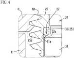
FIG. 4] FIG. 4 is an enlarged view of a part A inFIG. 2 . - [
FIG. 5] FIG. 5 is an enlarged view of a part B inFIG. 1 . - [
FIG. 6] FIG. 6 is a diagram illustrating a modification of a lock-side driving mechanism and is similar toFIG. 4 . - The following describes an embodiment of the present invention with reference to
FIG. 1 to FIG. 5 . - First of all, an overall structure of an electric clamping device of this embodiment will be described. A
housing 1 includes a lower housing 2 and an upper housing 3. Amotor 5 is attached to a side surface of the upper housing 3 via ajoint member 4. Adecelerator 6 is attached in the upper housing 3. The lower housing 2 is fixed to a table T functioning as a stationary stand by a plurality of bolts (not shown). Themotor 5 in this embodiment is a stepping motor. - As shown in
FIG. 3 , thedecelerator 6 in this embodiment is a worm decelerator. The worm decelerator includes: acylindrical worm 7 connected to an output shaft 5a of themotor 5; and aworm wheel 8 meshing with theworm 7. As shown inFIG. 3 ,shafts 7a and 7b provided at both axial end portions of theworm 7 are respectively supported bybearings worm 7 to be rotatable. Furthermore, as shown inFIG. 1 , a tubularjoint member 11 is fixed, for example, by press-fitting, to an axial end portion 8a of theworm wheel 8. Theworm wheel 8 to which thejoint member 11 is fixed is supported bybearings - An
output rod 20 is inserted in the housing 1 (the upper housing 3 and the lower housing 2) so as to be movable in an up-down direction (axial direction) toward a release side (upper side) and toward a lock side (lower side). Acap 21 is attached to a lower end portion of the lower housing 2, and thereby thehousing 1 is sealed. - The
output rod 20 includes: an output rodmain body 24; and a tubularpower transmission member 25 in which the output rodmain body 24 is inserted. Aclamp arm 22 is fixed to an upper end portion of the output rodmain body 24 by anut 23. The output rodmain body 24 is disposed radially inward of an inner peripheral surface of a cylindrical hole of thepower transmission member 25 with a clearance between them. The clearance is very small. - A
guide cylinder 40 configured to guide movement of the output rodmain body 24 in the axial direction is attached to an upper portion (release-side end portion) of the upper housing 3. Aguide cylinder 41 configured to guide movement of the output rodmain body 24 in the axial direction is attached a lower housing 2 (a lower portion (lock-side end portion) of the housing 1). - An external thread portion 25a (male feed screw portion) is provided on an outer peripheral surface of the
power transmission member 25. Aninternal thread portion 8b (female feed screw portion) meshing with the external thread portion 25a is provided on an inner peripheral surface of theworm wheel 8. At thefeed screw portions 25a and 8b, theworm wheel 8 is screw-connected to thepower transmission member 25. - Now, the
output rod 20 includes: arotation preventing mechanism 26; a lock-side driving mechanism 27; a release-side driving mechanism 28; and an outputrod guide mechanism 29. Each of these mechanisms will be described in order. - The
rotation preventing mechanism 26 is configured to prevent relative rotation between the output rodmain body 24 and thepower transmission member 25, and is structured as follows. As shown inFIG. 5 , at least one recess 24a is provided on an outer peripheral surface of the output rodmain body 24 and at least onerecess 25b is provided on an inner peripheral surface of thepower transmission member 25. In a space created by each recess 24a and the corresponding 25b, arotation preventing ball 30 is fitted. The number ofrotation preventing balls 30 is not limited. For example, fourrotation preventing balls 30 may be fitted in respective spaces created by therecesses 24a and 25b at intervals of 90 degrees in a circumferential direction of the output rodmain body 24. - The lock-
side driving mechanism 27 is configured to move the output rodmain body 24 toward the lock side via thepower transmission member 25, and is structured as follows. Aflange portion 31 protruding radially outward is provided on an outer periphery of the output rodmain body 24. As shown inFIG. 4 with reference numerals, an upper surface (release-side surface) of theflange portion 31 is a transmission surface 31a sloping toward the lock side relative to the axial direction. In this embodiment, the transmission surface 31a is shaped as a spherical surface. A portion of a lower (lock-side) inner surface of thepower transmission member 25, which faces the transmission surface 31a in the axial direction, functions as a push surface 32a configured to make surface contact with the transmission surface 31a. In this embodiment, the push surface 32a is shaped as a spherical surface. Thepower transmission member 25 has aring member 32, and an under surface of thering member 32 functions as the push surface 32a. The reason why thering member 32 is included in the power transmission member 25a as a separate component is to facilitate machine processing to form the push surface 32a. That is, thering member 32 is a component structuring thepower transmission member 25. - The release-
side driving mechanism 28 is configured to move the output rodmain body 24 toward the release side via thepower transmission member 25, and is structured as follows. As shown inFIG. 5 with reference numerals, an inner peripheral surface of a portion defining an upper end (release-side end) portion of the cylindrical hole of thepower transmission member 25 is aninclined surface 25c. Meanwhile, anannular groove 24c is provided at a portion of an outer periphery of the output rodmain body 24 which is radially opposed to theinclined surface 25c. A retainingring 33 is fitted in thegroove 24c. - The output
rod guide mechanism 29 is configured to guide movement of the output rodmain body 24 while preventing co-rotation of theoutput rod 20 with the worm wheel 8 (decelerator). The outputrod guide mechanism 29 is structured as follows. Theannular wall 34 protrudes upward (toward the release side) from an inner surface of the lower housing 2 (a lock-side inner surface of the housing 1). The output rodmain body 24 is inserted in a cylindrical hole of theannular wall 34. A plurality ofguide grooves 35 are provided on an outer periphery of the output rodmain body 24 at predetermined intervals in its circumferential direction. Eachguide groove 35 has arotation groove 36 and alinear groove 37 which are provided continuously from the lower side (lock side) toward the upper side (release side). Anengagement ball 38 is fitted in eachguide groove 35, and theengagement balls 38 are supported by theannular wall 34. Asleeve 39 is fitted over theengagement balls 38. - The electric clamping device having the above-described structure operates as follows.
- In a release state shown in
FIG. 1 , the output rodmain body 24 has been raised via thepower transmission member 25 to an upper limit position by theworm wheel 8 of thedecelerator 6 rotated by themotor 5 rotated for releasing. - To change the state of the electric clamping device from the release state of
FIG. 1 to a lock state ofFIG. 2 , themotor 5 is rotated for locking oppositely to the above, and then themotor 5 rotates thedecelerator 6, so that therotating worm wheel 8 lowers the output rodmain body 24 via thepower transmission member 25. - The descent process the output rod
main body 24 is described in detail. The rotational motion of theworm wheel 8 is converted to a linear motion at thefeed screw portions 8b and 25a and thereby thepower transmission member 25 descends. At this time, the push surface 32a of thering member 32 structuring thepower transmission member 25 pushes the transmission surface 31a of theflange portion 31 of the output rodmain body 24 and this makes the output rodmain body 24 descend. - It should be noted that the descent process of the output rod
main body 24 is achievable on the premise that: the relative rotation between the output rodmain body 24 and thepower transmission member 25 is prevented by therotation preventing mechanism 26; and the co-rotation of the output rod 20 (the output rodmain body 24 and the power transmission member 25) with theworm wheel 8 is prevented by the outputrod guide mechanism 29. The same can apply to an ascent process of the output rodmain body 24, which will be described later. - At an early stage of the descent process, the output rod 20 (the output rod
main body 24 and the power transmission member 25) descends while rotating along therotation grooves 36. Thereafter, theoutput rod 20 descends straight along thelinear grooves 37. When an under surface of theclamp arm 22 fixed to the upper end portion of the output rodmain body 24 comes into contact with a top surface of an object to be clamped such as a workpiece W, theclamp arm 22 presses (locks) the object onto the table T. - When the object is pressed from above, a reaction force from the object acts on the output rod
main body 24 to incline the output rodmain body 24. However, thepower transmission member 25 structuring theoutput rod 20 is provided as a separate member not unitary with the output rodmain body 24, and thepower transmission member 25 is disposed radially outward from the output rodmain body 24 with the clearance between them. Therefore, thepower transmission member 25 is less likely to be affected by the reaction force from the object, unlike the output rodmain body 24. Thus, it is possible to prevent deterioration in quality of engagement between thepower transmission member 25 and the decelerator 6 (deterioration in quality of mesh between thefeed screw portions 8b and 25a). Furthermore, in this embodiment, when the output rodmain body 24 is inclined relative to the axis by the reaction force from the object, the transmission surface 31a of the output rodmain body 24 is swayed on the spherical push surface 32a of thepower transmission member 25. Due to this, the surface contact between the transmission surface 31a and the push surface 32a is maintained both before and after the swaying motion of the output rodmain body 24. Consequently, a force pushing thepower transmission member 25 downward is reliably transmitted to the output rodmain body 24 via the push surface 32a and the transmission surface 31a. - To change the state of the electric clamping device from the lock state of
FIG. 2 to the release state ofFIG. 1 , themotor 5 is rotated for releasing. Then, themotor 5 rotates thedecelerator 6, so that therotating worm wheel 8 raises the output rodmain body 24 via thepower transmission member 25. - The ascent process of the output rod
main body 24 is described in detail. The rotational motion of theworm wheel 8 is converted to a linear motion at thefeed screw portions 8b and 25a and thereby thepower transmission member 25 ascends. Theinclined surface 25c at the upper end of the ascendingpower transmission member 25 pushes the output rodmain body 24 via the retainingring 33, and thereby the output rodmain body 24 ascends. - At an early stage of the ascent process, the output rod 20 (the output rod
main body 24 and the power transmission member 25) ascends straight along thelinear grooves 37. Thereafter, theoutput rod 20 ascends while rotating along therotation grooves 36. - The above-described embodiment is changeable as follows.
-
FIG. 6 is a diagram similar toFIG. 4 and illustrating a modification of the lock-side driving mechanism. A lock-side driving mechanism 42 shown inFIG. 6 is structured as follows. A recessedportion 31b is provided on an upper (release-side) surface of theflange portion 31 of the output rodmain body 24, and a plurality oftransmission balls 43 are fitted in the recessedportion 31b. Thetransmission balls 43 form a transmission surface 43a sloping toward the lock side relative to the axial direction. - Because the radius of curvature of the spherical push surface 32a of the power transmission member 25 (ring member 32) is larger than the radius of curvature of the transmission surface 43a formed by the transmission balls 43 (surfaces of the transmission balls 43), these surfaces 32a and 43a do not make surface contact. The both surfaces are, however, smooth spherical surfaces, and this stabilizes the swaying motion of the output rod
main body 24 at the time of locking an object. - The
transmission balls 43 may be disposed around the output rodmain body 24 on the entire circumference thereof without a gap between theballs 43. Alternatively, for example, two ormore transmission balls 43 may be disposed around the output rodmain body 24 with gaps between theballs 43. - The transmission surface 31a shown in
FIG. 4 , which slopes toward the lock side relative to the axial direction, is shaped as a spherical surface. Instead of the spherical surface, the transmission surface 31a may be a tapered surface whose section is a straight line. Alternatively, the transmission surface 31a may be formed by a plurality of inclined surfaces provided around the output rodmain body 24 at predetermined intervals. Still alternatively, the transmission surface may be a single inclined surface provided around the output rodmain body 24. In the case where the transmission surface is formed by one or two inclined surfaces, it is preferable to provide the inclined surface(s) at a position corresponding to a direction in which the output rodmain body 24 is swayed when viewing theoutput rod 20 along the axial direction. - In the above-described embodiment, the
power transmission member 25 includes thering member 32 as a separate component. Instead of this, the power thering member 32 may be unitarily included in thepower transmission member 25. That is, a power transmission member may be formed from a single material by machine processing. - In the above-described embodiment, the push surface 32a of the
power transmission member 25 is in contact with the transmission surface 31a of theflange portion 31 of the output rodmain body 24 in the release state ofFIG. 1 . Instead of this, there may be a gap in the axial direction between the push surface 32a of thepower transmission member 25 and the transmission surface 31a of theflange portion 31 of the output rodmain body 24 in the release state ofFIG. 1 . - The electric clamping device does not have to be of the type of device in which the
output rod 20 rotates, but may be of the type of device in which theoutput rod 20 moves only straight in the up-down direction. - The
motor 5 may be another type of motor instead of a stepping motor. Thedecelerator 6 is not limited to the worm decelerator, but may be structured by bevel gears. - Embodiments of the present invention have been hereinabove described.
- 1: housing; 5: motor; 6: decelerator; 20: output rod; 24: output rod main body; 25: power transmission member; 26: rotation preventing mechanism; 27, 42: lock-side driving mechanism; 28: release-side driving mechanism; 29: output rod guide mechanism; 31: flange portion; 31a, 43a: transmission surface; 31b: recessed portion; 32a: push surface; 34: annular wall; 35: guide groove; 36: rotation groove; 37: linear groove; 38: engagement ball; 40, 41: guide cylinder; 43: transmission ball.
Claims (8)
- An electric clamping device comprising:an output rod (20) inserted in a housing (1) so as to be movable in an axial direction toward a lock side and a release side;a motor (5) attached to the housing (1); anda decelerator (6) provided beside the output rod (20), the decelerator (6) configured to transmit rotational motion of the motor (5) to the output rod (20), whereinthe output rod (20) comprises:a tubular power transmission member (25) screw-connected to the decelerator (6);an output rod main body (24) disposed radially inward of an inner peripheral surface of a cylindrical hole of the power transmission member (25) with a clearance between the output rod main body (24) and the inner peripheral surface;a rotation preventing mechanism (26) configured to prevent relative rotation between the output rod main body (24) and the power transmission member (25);a lock-side driving mechanism (27, 42) configured to move the output rod main body (24) toward the lock side via the power transmission member (25);a release-side driving mechanism (28) configured to move the output rod main body (24) toward the release side via the power transmission member (25); andan output rod guide mechanism (29) configured to guide movement of the output rod main body (24) while preventing co-rotation with the decelerator (6).
- The electric clamping device according to claim 1,
wherein the lock-side driving mechanism (27, 42) comprises:a transmission surface (31a, 43a) provided at a release-side portion of a flange portion (31) provided on an outer periphery of the output rod main body (24), the transmission surface (31a, 43a) sloping toward the lock side relative to the axial direction; anda push surface (32a) provided on a lock-side inner surface of the power transmission member (25), andwherein when the motor (5) moves the power transmission member (25) to the lock side via the decelerator (6), the push surface (32a) pushes the transmission surface (31a, 43a) thereby to move the output rod main body (24) toward the lock side. - The electric clamping device according to claim 2, wherein
the transmission surface (31a, 43a) is shaped as a spherical surface. - The electric clamping device according to claim 3, wherein
the push surface (32a) is shaped as a spherical surface configured to make surface contact with the transmission surface (31a, 43a). - The electric clamping device according to claim 2, wherein
the transmission surface (43a) is structured by a plurality of transmission balls (43) fitted in a recessed portion (31b) provided on a release-side surface of the flange portion (31). - The electric clamping device according to any one of claims 1 to 5, wherein
guide cylinders (40, 41) configured to guide movement of the output rod main body (24) in the axial direction are respectively attached to a release-side end portion and a lock-side end portion of the housing (1). - The electric clamping device according to any one of claims 1 to 6, wherein:an annular wall (34) protrudes from a lock-side inner surface of the housing (1) toward the release side;the output rod main body (24) is inserted in the annular wall (34);the output rod guide mechanism (29) comprisesa plurality of guide grooves (35) provided on an outer periphery of the output rod main body (24) at predetermined intervals in its circumferential direction andengagement balls (38) supported by the annular wall (34), the engagement balls (38) respectively fitted in the guide grooves (35); andeach of the guide grooves (35) includes a rotation groove (36) and a linear groove (37) which are provided continuously from the lock side toward the release side.
- The electric clamping device according to any one of claims 1 to 7, wherein
the decelerator (6) is a worm decelerator.
Applications Claiming Priority (2)
| Application Number | Priority Date | Filing Date | Title |
|---|---|---|---|
| JP2017210078A JP6962557B2 (en) | 2017-10-31 | 2017-10-31 | Electric clamp device |
| PCT/JP2018/038308 WO2019087756A1 (en) | 2017-10-31 | 2018-10-15 | Electrically actuated clamp device |
Publications (3)
| Publication Number | Publication Date |
|---|---|
| EP3659745A1 EP3659745A1 (en) | 2020-06-03 |
| EP3659745A4 EP3659745A4 (en) | 2020-11-04 |
| EP3659745B1 true EP3659745B1 (en) | 2021-08-25 |
Family
ID=66333013
Family Applications (1)
| Application Number | Title | Priority Date | Filing Date |
|---|---|---|---|
| EP18872495.9A Active EP3659745B1 (en) | 2017-10-31 | 2018-10-15 | Electrically actuated clamp device |
Country Status (6)
| Country | Link |
|---|---|
| US (1) | US11305389B2 (en) |
| EP (1) | EP3659745B1 (en) |
| JP (1) | JP6962557B2 (en) |
| KR (1) | KR102481749B1 (en) |
| CN (1) | CN111246969B (en) |
| WO (1) | WO2019087756A1 (en) |
Families Citing this family (3)
| Publication number | Priority date | Publication date | Assignee | Title |
|---|---|---|---|---|
| JP6688644B2 (en) * | 2016-03-02 | 2020-04-28 | 株式会社コスメック | Clamp device with lift function |
| CN110935959B (en) * | 2019-12-16 | 2020-10-16 | 重庆电子工程职业学院 | A workpiece fixing device for new energy vehicle engine gear processing |
| CN114043296B (en) * | 2021-11-12 | 2023-12-22 | 安徽皖新电机有限公司 | Motor shell blanking device and operation method |
Family Cites Families (21)
| Publication number | Priority date | Publication date | Assignee | Title |
|---|---|---|---|---|
| DE3408188C1 (en) * | 1984-03-06 | 1985-04-25 | Germa Armaturen GmbH & Co KG Spezialarmaturen, 7253 Renningen | Fluid medium-actuated swivelling clamping device |
| DE3603618C1 (en) * | 1986-02-06 | 1987-10-01 | Friedhelm Hake | Clamping device for use on machine tools |
| US4700936A (en) * | 1986-08-26 | 1987-10-20 | Lamb Technicon Corp. | Clamp mechanism |
| DE3911073C1 (en) * | 1989-04-06 | 1990-07-26 | Kontec Gmbh, 6710 Frankenthal, De | |
| DE3912308C1 (en) * | 1989-04-14 | 1990-05-31 | Maschinenfabrik Hilma Gmbh, 5912 Hilchenbach, De | Swivel clam for machine tool - has housing which can be swung round limit angle in response to friction element engaged with drive spindle nut |
| JP3285061B2 (en) * | 1993-11-25 | 2002-05-27 | 豊田工機株式会社 | Workpiece clamping device |
| JPH1080833A (en) * | 1996-09-10 | 1998-03-31 | Kosmek Ltd | Swivel clamp device |
| TW579316B (en) * | 2001-11-13 | 2004-03-11 | Kosmek Ltd | Rotary clamp |
| JP3881589B2 (en) * | 2002-02-13 | 2007-02-14 | 株式会社コスメック | Cylinder device |
| JP4273484B2 (en) * | 2003-01-15 | 2009-06-03 | Smc株式会社 | Clamping device |
| JP4818947B2 (en) * | 2007-02-16 | 2011-11-16 | 株式会社コスメック | Clamping device and overstroke detection system for the device |
| JP2014004651A (en) * | 2012-06-22 | 2014-01-16 | Nitto Seiko Co Ltd | Rotary gripping chuck |
| JP5891535B2 (en) * | 2012-07-13 | 2016-03-23 | Smc株式会社 | Electric clamp device |
| JP6092710B2 (en) * | 2013-01-22 | 2017-03-08 | 株式会社コスメック | Cylinder device |
| KR101470151B1 (en) * | 2013-05-06 | 2014-12-05 | 현대자동차주식회사 | Jig system having clamp device |
| JP6227900B2 (en) * | 2013-05-15 | 2017-11-08 | 株式会社コスメック | Electric clamp device |
| JP6335443B2 (en) * | 2013-06-13 | 2018-05-30 | Ntn株式会社 | Electric brake device |
| FR3007497B1 (en) * | 2013-06-21 | 2015-11-20 | Batscap Sa | ROTO LINEAR CLAMP |
| EP2837466B1 (en) * | 2013-08-16 | 2018-08-01 | SMW-AUTOBLOK Spannsysteme GmbH | Clamping unit, in particular for use in a machining centre or a turning or milling center |
| CN205630300U (en) | 2016-04-14 | 2016-10-12 | 湖南汉诺科技有限公司 | Two flat grinder's quill feed unit |
| CN205873776U (en) * | 2016-06-29 | 2017-01-11 | 吴桥清大曙光传动设备有限公司 | Lift push rod |
-
2017
- 2017-10-31 JP JP2017210078A patent/JP6962557B2/en active Active
-
2018
- 2018-10-15 US US16/757,017 patent/US11305389B2/en active Active
- 2018-10-15 EP EP18872495.9A patent/EP3659745B1/en active Active
- 2018-10-15 WO PCT/JP2018/038308 patent/WO2019087756A1/en not_active Ceased
- 2018-10-15 CN CN201880068688.3A patent/CN111246969B/en active Active
- 2018-10-15 KR KR1020207007471A patent/KR102481749B1/en active Active
Also Published As
| Publication number | Publication date |
|---|---|
| US20200338675A1 (en) | 2020-10-29 |
| KR102481749B1 (en) | 2022-12-27 |
| WO2019087756A1 (en) | 2019-05-09 |
| JP2019081220A (en) | 2019-05-30 |
| EP3659745A4 (en) | 2020-11-04 |
| EP3659745A1 (en) | 2020-06-03 |
| KR20200075817A (en) | 2020-06-26 |
| CN111246969A (en) | 2020-06-05 |
| CN111246969B (en) | 2021-10-19 |
| JP6962557B2 (en) | 2021-11-05 |
| US11305389B2 (en) | 2022-04-19 |
Similar Documents
| Publication | Publication Date | Title |
|---|---|---|
| US11305389B2 (en) | Electric clamping device | |
| JP6632537B2 (en) | Actuator with planetary rolling threaded spindle (PWG) | |
| US8656798B2 (en) | Linear actuator | |
| EP3534037B1 (en) | Electric actuator | |
| CN1022438C (en) | Method for forming roller bearings of very small axial dimension and high load-carrying capacity | |
| EP0572543B1 (en) | Miniature linear actuator | |
| KR102556195B1 (en) | assembling jig for pin gear roller screw | |
| US3219228A (en) | Ball lock clamping devices | |
| KR101567500B1 (en) | Reduction apparatus | |
| JP2018194109A (en) | Electric actuator | |
| KR20200016963A (en) | Manufacturing apparatus of bearing unit and manufacturing method of bearing unit | |
| CN107088855A (en) | A kind of clutch oil sealing cap dismantling device | |
| KR102673515B1 (en) | actuator of side step unit | |
| EP0543998B1 (en) | Lift device | |
| CN107747597B (en) | A kind of dedicated switching of 10 tonnes of planetary roller screw load tests and fixed device | |
| KR20210006863A (en) | Decelerator | |
| EP4317745A1 (en) | Ball screw device | |
| CN110206428A (en) | A kind of non-co-planar hinge of shaft and the robot with the hinge | |
| EP3423724B1 (en) | Apparatus and method for preloading bearing assemblies | |
| US12241528B2 (en) | Ball screw drive with an anti-rotation safeguard | |
| CN209724967U (en) | A kind of Self-aligning zero clearance follower | |
| CN207753554U (en) | A kind of servo electric jar system | |
| CN205873776U (en) | Lift push rod | |
| EP4471290A1 (en) | Ball screw device and electric actuator provided with same | |
| CN220748984U (en) | Transmission device for linear actuator and linear actuator |
Legal Events
| Date | Code | Title | Description |
|---|---|---|---|
| STAA | Information on the status of an ep patent application or granted ep patent |
Free format text: STATUS: THE INTERNATIONAL PUBLICATION HAS BEEN MADE |
|
| PUAI | Public reference made under article 153(3) epc to a published international application that has entered the european phase |
Free format text: ORIGINAL CODE: 0009012 |
|
| STAA | Information on the status of an ep patent application or granted ep patent |
Free format text: STATUS: REQUEST FOR EXAMINATION WAS MADE |
|
| 17P | Request for examination filed |
Effective date: 20200226 |
|
| AK | Designated contracting states |
Kind code of ref document: A1 Designated state(s): AL AT BE BG CH CY CZ DE DK EE ES FI FR GB GR HR HU IE IS IT LI LT LU LV MC MK MT NL NO PL PT RO RS SE SI SK SM TR |
|
| AX | Request for extension of the european patent |
Extension state: BA ME |
|
| A4 | Supplementary search report drawn up and despatched |
Effective date: 20201005 |
|
| RIC1 | Information provided on ipc code assigned before grant |
Ipc: B25B 5/06 20060101ALI20200929BHEP Ipc: B23Q 3/06 20060101AFI20200929BHEP Ipc: B25B 5/10 20060101ALI20200929BHEP |
|
| DAV | Request for validation of the european patent (deleted) | ||
| DAX | Request for extension of the european patent (deleted) | ||
| GRAP | Despatch of communication of intention to grant a patent |
Free format text: ORIGINAL CODE: EPIDOSNIGR1 |
|
| STAA | Information on the status of an ep patent application or granted ep patent |
Free format text: STATUS: GRANT OF PATENT IS INTENDED |
|
| RIC1 | Information provided on ipc code assigned before grant |
Ipc: B23Q 3/06 20060101AFI20210226BHEP Ipc: B25B 5/06 20060101ALI20210226BHEP Ipc: B25B 5/10 20060101ALI20210226BHEP |
|
| INTG | Intention to grant announced |
Effective date: 20210326 |
|
| GRAS | Grant fee paid |
Free format text: ORIGINAL CODE: EPIDOSNIGR3 |
|
| GRAA | (expected) grant |
Free format text: ORIGINAL CODE: 0009210 |
|
| STAA | Information on the status of an ep patent application or granted ep patent |
Free format text: STATUS: THE PATENT HAS BEEN GRANTED |
|
| AK | Designated contracting states |
Kind code of ref document: B1 Designated state(s): AL AT BE BG CH CY CZ DE DK EE ES FI FR GB GR HR HU IE IS IT LI LT LU LV MC MK MT NL NO PL PT RO RS SE SI SK SM TR |
|
| REG | Reference to a national code |
Ref country code: CH Ref legal event code: EP |
|
| REG | Reference to a national code |
Ref country code: DE Ref legal event code: R096 Ref document number: 602018022606 Country of ref document: DE |
|
| REG | Reference to a national code |
Ref country code: IE Ref legal event code: FG4D Ref country code: AT Ref legal event code: REF Ref document number: 1423296 Country of ref document: AT Kind code of ref document: T Effective date: 20210915 |
|
| REG | Reference to a national code |
Ref country code: LT Ref legal event code: MG9D |
|
| REG | Reference to a national code |
Ref country code: NL Ref legal event code: MP Effective date: 20210825 |
|
| REG | Reference to a national code |
Ref country code: AT Ref legal event code: MK05 Ref document number: 1423296 Country of ref document: AT Kind code of ref document: T Effective date: 20210825 |
|
| PG25 | Lapsed in a contracting state [announced via postgrant information from national office to epo] |
Ref country code: RS Free format text: LAPSE BECAUSE OF FAILURE TO SUBMIT A TRANSLATION OF THE DESCRIPTION OR TO PAY THE FEE WITHIN THE PRESCRIBED TIME-LIMIT Effective date: 20210825 Ref country code: SE Free format text: LAPSE BECAUSE OF FAILURE TO SUBMIT A TRANSLATION OF THE DESCRIPTION OR TO PAY THE FEE WITHIN THE PRESCRIBED TIME-LIMIT Effective date: 20210825 Ref country code: ES Free format text: LAPSE BECAUSE OF FAILURE TO SUBMIT A TRANSLATION OF THE DESCRIPTION OR TO PAY THE FEE WITHIN THE PRESCRIBED TIME-LIMIT Effective date: 20210825 Ref country code: FI Free format text: LAPSE BECAUSE OF FAILURE TO SUBMIT A TRANSLATION OF THE DESCRIPTION OR TO PAY THE FEE WITHIN THE PRESCRIBED TIME-LIMIT Effective date: 20210825 Ref country code: LT Free format text: LAPSE BECAUSE OF FAILURE TO SUBMIT A TRANSLATION OF THE DESCRIPTION OR TO PAY THE FEE WITHIN THE PRESCRIBED TIME-LIMIT Effective date: 20210825 Ref country code: AT Free format text: LAPSE BECAUSE OF FAILURE TO SUBMIT A TRANSLATION OF THE DESCRIPTION OR TO PAY THE FEE WITHIN THE PRESCRIBED TIME-LIMIT Effective date: 20210825 Ref country code: BG Free format text: LAPSE BECAUSE OF FAILURE TO SUBMIT A TRANSLATION OF THE DESCRIPTION OR TO PAY THE FEE WITHIN THE PRESCRIBED TIME-LIMIT Effective date: 20211125 Ref country code: NO Free format text: LAPSE BECAUSE OF FAILURE TO SUBMIT A TRANSLATION OF THE DESCRIPTION OR TO PAY THE FEE WITHIN THE PRESCRIBED TIME-LIMIT Effective date: 20211125 Ref country code: PT Free format text: LAPSE BECAUSE OF FAILURE TO SUBMIT A TRANSLATION OF THE DESCRIPTION OR TO PAY THE FEE WITHIN THE PRESCRIBED TIME-LIMIT Effective date: 20211227 Ref country code: HR Free format text: LAPSE BECAUSE OF FAILURE TO SUBMIT A TRANSLATION OF THE DESCRIPTION OR TO PAY THE FEE WITHIN THE PRESCRIBED TIME-LIMIT Effective date: 20210825 |
|
| PG25 | Lapsed in a contracting state [announced via postgrant information from national office to epo] |
Ref country code: PL Free format text: LAPSE BECAUSE OF FAILURE TO SUBMIT A TRANSLATION OF THE DESCRIPTION OR TO PAY THE FEE WITHIN THE PRESCRIBED TIME-LIMIT Effective date: 20210825 Ref country code: LV Free format text: LAPSE BECAUSE OF FAILURE TO SUBMIT A TRANSLATION OF THE DESCRIPTION OR TO PAY THE FEE WITHIN THE PRESCRIBED TIME-LIMIT Effective date: 20210825 Ref country code: GR Free format text: LAPSE BECAUSE OF FAILURE TO SUBMIT A TRANSLATION OF THE DESCRIPTION OR TO PAY THE FEE WITHIN THE PRESCRIBED TIME-LIMIT Effective date: 20211126 |
|
| PG25 | Lapsed in a contracting state [announced via postgrant information from national office to epo] |
Ref country code: NL Free format text: LAPSE BECAUSE OF FAILURE TO SUBMIT A TRANSLATION OF THE DESCRIPTION OR TO PAY THE FEE WITHIN THE PRESCRIBED TIME-LIMIT Effective date: 20210825 |
|
| PG25 | Lapsed in a contracting state [announced via postgrant information from national office to epo] |
Ref country code: DK Free format text: LAPSE BECAUSE OF FAILURE TO SUBMIT A TRANSLATION OF THE DESCRIPTION OR TO PAY THE FEE WITHIN THE PRESCRIBED TIME-LIMIT Effective date: 20210825 |
|
| REG | Reference to a national code |
Ref country code: DE Ref legal event code: R097 Ref document number: 602018022606 Country of ref document: DE |
|
| REG | Reference to a national code |
Ref country code: CH Ref legal event code: PL |
|
| PG25 | Lapsed in a contracting state [announced via postgrant information from national office to epo] |
Ref country code: SM Free format text: LAPSE BECAUSE OF FAILURE TO SUBMIT A TRANSLATION OF THE DESCRIPTION OR TO PAY THE FEE WITHIN THE PRESCRIBED TIME-LIMIT Effective date: 20210825 Ref country code: SK Free format text: LAPSE BECAUSE OF FAILURE TO SUBMIT A TRANSLATION OF THE DESCRIPTION OR TO PAY THE FEE WITHIN THE PRESCRIBED TIME-LIMIT Effective date: 20210825 Ref country code: RO Free format text: LAPSE BECAUSE OF FAILURE TO SUBMIT A TRANSLATION OF THE DESCRIPTION OR TO PAY THE FEE WITHIN THE PRESCRIBED TIME-LIMIT Effective date: 20210825 Ref country code: EE Free format text: LAPSE BECAUSE OF FAILURE TO SUBMIT A TRANSLATION OF THE DESCRIPTION OR TO PAY THE FEE WITHIN THE PRESCRIBED TIME-LIMIT Effective date: 20210825 Ref country code: CZ Free format text: LAPSE BECAUSE OF FAILURE TO SUBMIT A TRANSLATION OF THE DESCRIPTION OR TO PAY THE FEE WITHIN THE PRESCRIBED TIME-LIMIT Effective date: 20210825 Ref country code: AL Free format text: LAPSE BECAUSE OF FAILURE TO SUBMIT A TRANSLATION OF THE DESCRIPTION OR TO PAY THE FEE WITHIN THE PRESCRIBED TIME-LIMIT Effective date: 20210825 |
|
| REG | Reference to a national code |
Ref country code: BE Ref legal event code: MM Effective date: 20211031 |
|
| PG25 | Lapsed in a contracting state [announced via postgrant information from national office to epo] |
Ref country code: MC Free format text: LAPSE BECAUSE OF FAILURE TO SUBMIT A TRANSLATION OF THE DESCRIPTION OR TO PAY THE FEE WITHIN THE PRESCRIBED TIME-LIMIT Effective date: 20210825 |
|
| PLBE | No opposition filed within time limit |
Free format text: ORIGINAL CODE: 0009261 |
|
| STAA | Information on the status of an ep patent application or granted ep patent |
Free format text: STATUS: NO OPPOSITION FILED WITHIN TIME LIMIT |
|
| PG25 | Lapsed in a contracting state [announced via postgrant information from national office to epo] |
Ref country code: LU Free format text: LAPSE BECAUSE OF NON-PAYMENT OF DUE FEES Effective date: 20211015 Ref country code: BE Free format text: LAPSE BECAUSE OF NON-PAYMENT OF DUE FEES Effective date: 20211031 |
|
| 26N | No opposition filed |
Effective date: 20220527 |
|
| PG25 | Lapsed in a contracting state [announced via postgrant information from national office to epo] |
Ref country code: SI Free format text: LAPSE BECAUSE OF FAILURE TO SUBMIT A TRANSLATION OF THE DESCRIPTION OR TO PAY THE FEE WITHIN THE PRESCRIBED TIME-LIMIT Effective date: 20210825 Ref country code: LI Free format text: LAPSE BECAUSE OF NON-PAYMENT OF DUE FEES Effective date: 20211031 Ref country code: CH Free format text: LAPSE BECAUSE OF NON-PAYMENT OF DUE FEES Effective date: 20211031 |
|
| PG25 | Lapsed in a contracting state [announced via postgrant information from national office to epo] |
Ref country code: FR Free format text: LAPSE BECAUSE OF NON-PAYMENT OF DUE FEES Effective date: 20211025 |
|
| PG25 | Lapsed in a contracting state [announced via postgrant information from national office to epo] |
Ref country code: IE Free format text: LAPSE BECAUSE OF NON-PAYMENT OF DUE FEES Effective date: 20211015 |
|
| P01 | Opt-out of the competence of the unified patent court (upc) registered |
Effective date: 20230404 |
|
| GBPC | Gb: european patent ceased through non-payment of renewal fee |
Effective date: 20221015 |
|
| PG25 | Lapsed in a contracting state [announced via postgrant information from national office to epo] |
Ref country code: CY Free format text: LAPSE BECAUSE OF FAILURE TO SUBMIT A TRANSLATION OF THE DESCRIPTION OR TO PAY THE FEE WITHIN THE PRESCRIBED TIME-LIMIT Effective date: 20210825 |
|
| PG25 | Lapsed in a contracting state [announced via postgrant information from national office to epo] |
Ref country code: HU Free format text: LAPSE BECAUSE OF FAILURE TO SUBMIT A TRANSLATION OF THE DESCRIPTION OR TO PAY THE FEE WITHIN THE PRESCRIBED TIME-LIMIT; INVALID AB INITIO Effective date: 20181015 |
|
| PG25 | Lapsed in a contracting state [announced via postgrant information from national office to epo] |
Ref country code: GB Free format text: LAPSE BECAUSE OF NON-PAYMENT OF DUE FEES Effective date: 20221015 |
|
| PG25 | Lapsed in a contracting state [announced via postgrant information from national office to epo] |
Ref country code: MK Free format text: LAPSE BECAUSE OF FAILURE TO SUBMIT A TRANSLATION OF THE DESCRIPTION OR TO PAY THE FEE WITHIN THE PRESCRIBED TIME-LIMIT Effective date: 20210825 |
|
| PG25 | Lapsed in a contracting state [announced via postgrant information from national office to epo] |
Ref country code: MT Free format text: LAPSE BECAUSE OF FAILURE TO SUBMIT A TRANSLATION OF THE DESCRIPTION OR TO PAY THE FEE WITHIN THE PRESCRIBED TIME-LIMIT Effective date: 20210825 |
|
| PG25 | Lapsed in a contracting state [announced via postgrant information from national office to epo] |
Ref country code: TR Free format text: LAPSE BECAUSE OF FAILURE TO SUBMIT A TRANSLATION OF THE DESCRIPTION OR TO PAY THE FEE WITHIN THE PRESCRIBED TIME-LIMIT Effective date: 20210825 |
|
| PGFP | Annual fee paid to national office [announced via postgrant information from national office to epo] |
Ref country code: DE Payment date: 20251021 Year of fee payment: 8 |
|
| PGFP | Annual fee paid to national office [announced via postgrant information from national office to epo] |
Ref country code: IT Payment date: 20251024 Year of fee payment: 8 |