EP3659668A1 - Tube joining device - Google Patents
Tube joining device Download PDFInfo
- Publication number
- EP3659668A1 EP3659668A1 EP18839289.8A EP18839289A EP3659668A1 EP 3659668 A1 EP3659668 A1 EP 3659668A1 EP 18839289 A EP18839289 A EP 18839289A EP 3659668 A1 EP3659668 A1 EP 3659668A1
- Authority
- EP
- European Patent Office
- Prior art keywords
- tube
- housing
- lid
- holding part
- tubes
- Prior art date
- Legal status (The legal status is an assumption and is not a legal conclusion. Google has not performed a legal analysis and makes no representation as to the accuracy of the status listed.)
- Granted
Links
Images







Classifications
-
- B—PERFORMING OPERATIONS; TRANSPORTING
- B29—WORKING OF PLASTICS; WORKING OF SUBSTANCES IN A PLASTIC STATE IN GENERAL
- B29C—SHAPING OR JOINING OF PLASTICS; SHAPING OF MATERIAL IN A PLASTIC STATE, NOT OTHERWISE PROVIDED FOR; AFTER-TREATMENT OF THE SHAPED PRODUCTS, e.g. REPAIRING
- B29C66/00—General aspects of processes or apparatus for joining preformed parts
- B29C66/80—General aspects of machine operations or constructions and parts thereof
- B29C66/87—Auxiliary operations or devices
- B29C66/874—Safety measures or devices
- B29C66/8746—Detecting the absence of the articles to be joined
-
- A—HUMAN NECESSITIES
- A61—MEDICAL OR VETERINARY SCIENCE; HYGIENE
- A61M—DEVICES FOR INTRODUCING MEDIA INTO, OR ONTO, THE BODY; DEVICES FOR TRANSDUCING BODY MEDIA OR FOR TAKING MEDIA FROM THE BODY; DEVICES FOR PRODUCING OR ENDING SLEEP OR STUPOR
- A61M39/00—Tubes, tube connectors, tube couplings, valves, access sites or the like, specially adapted for medical use
- A61M39/10—Tube connectors; Tube couplings
- A61M39/14—Tube connectors; Tube couplings for connecting tubes having sealed ends
- A61M39/146—Tube connectors; Tube couplings for connecting tubes having sealed ends by cutting and welding
-
- B—PERFORMING OPERATIONS; TRANSPORTING
- B29—WORKING OF PLASTICS; WORKING OF SUBSTANCES IN A PLASTIC STATE IN GENERAL
- B29C—SHAPING OR JOINING OF PLASTICS; SHAPING OF MATERIAL IN A PLASTIC STATE, NOT OTHERWISE PROVIDED FOR; AFTER-TREATMENT OF THE SHAPED PRODUCTS, e.g. REPAIRING
- B29C65/00—Joining or sealing of preformed parts, e.g. welding of plastics materials; Apparatus therefor
- B29C65/02—Joining or sealing of preformed parts, e.g. welding of plastics materials; Apparatus therefor by heating, with or without pressure
- B29C65/18—Joining or sealing of preformed parts, e.g. welding of plastics materials; Apparatus therefor by heating, with or without pressure using heated tools
- B29C65/20—Joining or sealing of preformed parts, e.g. welding of plastics materials; Apparatus therefor by heating, with or without pressure using heated tools with direct contact, e.g. using "mirror"
- B29C65/2007—Joining or sealing of preformed parts, e.g. welding of plastics materials; Apparatus therefor by heating, with or without pressure using heated tools with direct contact, e.g. using "mirror" characterised by the type of welding mirror
- B29C65/203—Joining or sealing of preformed parts, e.g. welding of plastics materials; Apparatus therefor by heating, with or without pressure using heated tools with direct contact, e.g. using "mirror" characterised by the type of welding mirror being several single mirrors, e.g. not mounted on the same tool
-
- B—PERFORMING OPERATIONS; TRANSPORTING
- B29—WORKING OF PLASTICS; WORKING OF SUBSTANCES IN A PLASTIC STATE IN GENERAL
- B29C—SHAPING OR JOINING OF PLASTICS; SHAPING OF MATERIAL IN A PLASTIC STATE, NOT OTHERWISE PROVIDED FOR; AFTER-TREATMENT OF THE SHAPED PRODUCTS, e.g. REPAIRING
- B29C65/00—Joining or sealing of preformed parts, e.g. welding of plastics materials; Apparatus therefor
- B29C65/02—Joining or sealing of preformed parts, e.g. welding of plastics materials; Apparatus therefor by heating, with or without pressure
- B29C65/18—Joining or sealing of preformed parts, e.g. welding of plastics materials; Apparatus therefor by heating, with or without pressure using heated tools
- B29C65/20—Joining or sealing of preformed parts, e.g. welding of plastics materials; Apparatus therefor by heating, with or without pressure using heated tools with direct contact, e.g. using "mirror"
- B29C65/2046—Joining or sealing of preformed parts, e.g. welding of plastics materials; Apparatus therefor by heating, with or without pressure using heated tools with direct contact, e.g. using "mirror" using a welding mirror which also cuts the parts to be joined, e.g. for sterile welding
-
- B—PERFORMING OPERATIONS; TRANSPORTING
- B29—WORKING OF PLASTICS; WORKING OF SUBSTANCES IN A PLASTIC STATE IN GENERAL
- B29C—SHAPING OR JOINING OF PLASTICS; SHAPING OF MATERIAL IN A PLASTIC STATE, NOT OTHERWISE PROVIDED FOR; AFTER-TREATMENT OF THE SHAPED PRODUCTS, e.g. REPAIRING
- B29C65/00—Joining or sealing of preformed parts, e.g. welding of plastics materials; Apparatus therefor
- B29C65/02—Joining or sealing of preformed parts, e.g. welding of plastics materials; Apparatus therefor by heating, with or without pressure
- B29C65/18—Joining or sealing of preformed parts, e.g. welding of plastics materials; Apparatus therefor by heating, with or without pressure using heated tools
- B29C65/20—Joining or sealing of preformed parts, e.g. welding of plastics materials; Apparatus therefor by heating, with or without pressure using heated tools with direct contact, e.g. using "mirror"
- B29C65/2053—Joining or sealing of preformed parts, e.g. welding of plastics materials; Apparatus therefor by heating, with or without pressure using heated tools with direct contact, e.g. using "mirror" characterised by special ways of bringing the welding mirrors into position
- B29C65/2061—Joining or sealing of preformed parts, e.g. welding of plastics materials; Apparatus therefor by heating, with or without pressure using heated tools with direct contact, e.g. using "mirror" characterised by special ways of bringing the welding mirrors into position by sliding
-
- B—PERFORMING OPERATIONS; TRANSPORTING
- B29—WORKING OF PLASTICS; WORKING OF SUBSTANCES IN A PLASTIC STATE IN GENERAL
- B29C—SHAPING OR JOINING OF PLASTICS; SHAPING OF MATERIAL IN A PLASTIC STATE, NOT OTHERWISE PROVIDED FOR; AFTER-TREATMENT OF THE SHAPED PRODUCTS, e.g. REPAIRING
- B29C65/00—Joining or sealing of preformed parts, e.g. welding of plastics materials; Apparatus therefor
- B29C65/02—Joining or sealing of preformed parts, e.g. welding of plastics materials; Apparatus therefor by heating, with or without pressure
- B29C65/18—Joining or sealing of preformed parts, e.g. welding of plastics materials; Apparatus therefor by heating, with or without pressure using heated tools
- B29C65/20—Joining or sealing of preformed parts, e.g. welding of plastics materials; Apparatus therefor by heating, with or without pressure using heated tools with direct contact, e.g. using "mirror"
- B29C65/2053—Joining or sealing of preformed parts, e.g. welding of plastics materials; Apparatus therefor by heating, with or without pressure using heated tools with direct contact, e.g. using "mirror" characterised by special ways of bringing the welding mirrors into position
- B29C65/2061—Joining or sealing of preformed parts, e.g. welding of plastics materials; Apparatus therefor by heating, with or without pressure using heated tools with direct contact, e.g. using "mirror" characterised by special ways of bringing the welding mirrors into position by sliding
- B29C65/2069—Joining or sealing of preformed parts, e.g. welding of plastics materials; Apparatus therefor by heating, with or without pressure using heated tools with direct contact, e.g. using "mirror" characterised by special ways of bringing the welding mirrors into position by sliding with an angle with respect to the plane comprising the parts to be joined
- B29C65/2076—Joining or sealing of preformed parts, e.g. welding of plastics materials; Apparatus therefor by heating, with or without pressure using heated tools with direct contact, e.g. using "mirror" characterised by special ways of bringing the welding mirrors into position by sliding with an angle with respect to the plane comprising the parts to be joined perpendicularly to the plane comprising the parts to be joined
-
- B—PERFORMING OPERATIONS; TRANSPORTING
- B29—WORKING OF PLASTICS; WORKING OF SUBSTANCES IN A PLASTIC STATE IN GENERAL
- B29C—SHAPING OR JOINING OF PLASTICS; SHAPING OF MATERIAL IN A PLASTIC STATE, NOT OTHERWISE PROVIDED FOR; AFTER-TREATMENT OF THE SHAPED PRODUCTS, e.g. REPAIRING
- B29C65/00—Joining or sealing of preformed parts, e.g. welding of plastics materials; Apparatus therefor
- B29C65/78—Means for handling the parts to be joined, e.g. for making containers or hollow articles, e.g. means for handling sheets, plates, web-like materials, tubular articles, hollow articles or elements to be joined therewith; Means for discharging the joined articles from the joining apparatus
- B29C65/7802—Positioning the parts to be joined, e.g. aligning, indexing or centring
-
- B—PERFORMING OPERATIONS; TRANSPORTING
- B29—WORKING OF PLASTICS; WORKING OF SUBSTANCES IN A PLASTIC STATE IN GENERAL
- B29C—SHAPING OR JOINING OF PLASTICS; SHAPING OF MATERIAL IN A PLASTIC STATE, NOT OTHERWISE PROVIDED FOR; AFTER-TREATMENT OF THE SHAPED PRODUCTS, e.g. REPAIRING
- B29C65/00—Joining or sealing of preformed parts, e.g. welding of plastics materials; Apparatus therefor
- B29C65/78—Means for handling the parts to be joined, e.g. for making containers or hollow articles, e.g. means for handling sheets, plates, web-like materials, tubular articles, hollow articles or elements to be joined therewith; Means for discharging the joined articles from the joining apparatus
- B29C65/7841—Holding or clamping means for handling purposes
-
- B—PERFORMING OPERATIONS; TRANSPORTING
- B29—WORKING OF PLASTICS; WORKING OF SUBSTANCES IN A PLASTIC STATE IN GENERAL
- B29C—SHAPING OR JOINING OF PLASTICS; SHAPING OF MATERIAL IN A PLASTIC STATE, NOT OTHERWISE PROVIDED FOR; AFTER-TREATMENT OF THE SHAPED PRODUCTS, e.g. REPAIRING
- B29C66/00—General aspects of processes or apparatus for joining preformed parts
- B29C66/001—Joining in special atmospheres
- B29C66/0012—Joining in special atmospheres characterised by the type of environment
- B29C66/0018—Joining in special atmospheres characterised by the type of environment being sterile
-
- B—PERFORMING OPERATIONS; TRANSPORTING
- B29—WORKING OF PLASTICS; WORKING OF SUBSTANCES IN A PLASTIC STATE IN GENERAL
- B29C—SHAPING OR JOINING OF PLASTICS; SHAPING OF MATERIAL IN A PLASTIC STATE, NOT OTHERWISE PROVIDED FOR; AFTER-TREATMENT OF THE SHAPED PRODUCTS, e.g. REPAIRING
- B29C66/00—General aspects of processes or apparatus for joining preformed parts
- B29C66/002—Removing toxic gases
-
- B—PERFORMING OPERATIONS; TRANSPORTING
- B29—WORKING OF PLASTICS; WORKING OF SUBSTANCES IN A PLASTIC STATE IN GENERAL
- B29C—SHAPING OR JOINING OF PLASTICS; SHAPING OF MATERIAL IN A PLASTIC STATE, NOT OTHERWISE PROVIDED FOR; AFTER-TREATMENT OF THE SHAPED PRODUCTS, e.g. REPAIRING
- B29C66/00—General aspects of processes or apparatus for joining preformed parts
- B29C66/01—General aspects dealing with the joint area or with the area to be joined
- B29C66/05—Particular design of joint configurations
- B29C66/10—Particular design of joint configurations particular design of the joint cross-sections
- B29C66/11—Joint cross-sections comprising a single joint-segment, i.e. one of the parts to be joined comprising a single joint-segment in the joint cross-section
- B29C66/114—Single butt joints
- B29C66/1142—Single butt to butt joints
-
- B—PERFORMING OPERATIONS; TRANSPORTING
- B29—WORKING OF PLASTICS; WORKING OF SUBSTANCES IN A PLASTIC STATE IN GENERAL
- B29C—SHAPING OR JOINING OF PLASTICS; SHAPING OF MATERIAL IN A PLASTIC STATE, NOT OTHERWISE PROVIDED FOR; AFTER-TREATMENT OF THE SHAPED PRODUCTS, e.g. REPAIRING
- B29C66/00—General aspects of processes or apparatus for joining preformed parts
- B29C66/50—General aspects of joining tubular articles; General aspects of joining long products, i.e. bars or profiled elements; General aspects of joining single elements to tubular articles, hollow articles or bars; General aspects of joining several hollow-preforms to form hollow or tubular articles
- B29C66/51—Joining tubular articles, profiled elements or bars; Joining single elements to tubular articles, hollow articles or bars; Joining several hollow-preforms to form hollow or tubular articles
- B29C66/52—Joining tubular articles, bars or profiled elements
- B29C66/522—Joining tubular articles
- B29C66/5221—Joining tubular articles for forming coaxial connections, i.e. the tubular articles to be joined forming a zero angle relative to each other
-
- B—PERFORMING OPERATIONS; TRANSPORTING
- B29—WORKING OF PLASTICS; WORKING OF SUBSTANCES IN A PLASTIC STATE IN GENERAL
- B29C—SHAPING OR JOINING OF PLASTICS; SHAPING OF MATERIAL IN A PLASTIC STATE, NOT OTHERWISE PROVIDED FOR; AFTER-TREATMENT OF THE SHAPED PRODUCTS, e.g. REPAIRING
- B29C66/00—General aspects of processes or apparatus for joining preformed parts
- B29C66/70—General aspects of processes or apparatus for joining preformed parts characterised by the composition, physical properties or the structure of the material of the parts to be joined; Joining with non-plastics material
- B29C66/73—General aspects of processes or apparatus for joining preformed parts characterised by the composition, physical properties or the structure of the material of the parts to be joined; Joining with non-plastics material characterised by the intensive physical properties of the material of the parts to be joined, by the optical properties of the material of the parts to be joined, by the extensive physical properties of the parts to be joined, by the state of the material of the parts to be joined or by the material of the parts to be joined being a thermoplastic or a thermoset
- B29C66/737—General aspects of processes or apparatus for joining preformed parts characterised by the composition, physical properties or the structure of the material of the parts to be joined; Joining with non-plastics material characterised by the intensive physical properties of the material of the parts to be joined, by the optical properties of the material of the parts to be joined, by the extensive physical properties of the parts to be joined, by the state of the material of the parts to be joined or by the material of the parts to be joined being a thermoplastic or a thermoset characterised by the state of the material of the parts to be joined
- B29C66/7373—Joining soiled or oxidised materials
-
- B—PERFORMING OPERATIONS; TRANSPORTING
- B29—WORKING OF PLASTICS; WORKING OF SUBSTANCES IN A PLASTIC STATE IN GENERAL
- B29C—SHAPING OR JOINING OF PLASTICS; SHAPING OF MATERIAL IN A PLASTIC STATE, NOT OTHERWISE PROVIDED FOR; AFTER-TREATMENT OF THE SHAPED PRODUCTS, e.g. REPAIRING
- B29C66/00—General aspects of processes or apparatus for joining preformed parts
- B29C66/70—General aspects of processes or apparatus for joining preformed parts characterised by the composition, physical properties or the structure of the material of the parts to be joined; Joining with non-plastics material
- B29C66/73—General aspects of processes or apparatus for joining preformed parts characterised by the composition, physical properties or the structure of the material of the parts to be joined; Joining with non-plastics material characterised by the intensive physical properties of the material of the parts to be joined, by the optical properties of the material of the parts to be joined, by the extensive physical properties of the parts to be joined, by the state of the material of the parts to be joined or by the material of the parts to be joined being a thermoplastic or a thermoset
- B29C66/739—General aspects of processes or apparatus for joining preformed parts characterised by the composition, physical properties or the structure of the material of the parts to be joined; Joining with non-plastics material characterised by the intensive physical properties of the material of the parts to be joined, by the optical properties of the material of the parts to be joined, by the extensive physical properties of the parts to be joined, by the state of the material of the parts to be joined or by the material of the parts to be joined being a thermoplastic or a thermoset characterised by the material of the parts to be joined being a thermoplastic or a thermoset
- B29C66/7392—General aspects of processes or apparatus for joining preformed parts characterised by the composition, physical properties or the structure of the material of the parts to be joined; Joining with non-plastics material characterised by the intensive physical properties of the material of the parts to be joined, by the optical properties of the material of the parts to be joined, by the extensive physical properties of the parts to be joined, by the state of the material of the parts to be joined or by the material of the parts to be joined being a thermoplastic or a thermoset characterised by the material of the parts to be joined being a thermoplastic or a thermoset characterised by the material of at least one of the parts being a thermoplastic
- B29C66/73921—General aspects of processes or apparatus for joining preformed parts characterised by the composition, physical properties or the structure of the material of the parts to be joined; Joining with non-plastics material characterised by the intensive physical properties of the material of the parts to be joined, by the optical properties of the material of the parts to be joined, by the extensive physical properties of the parts to be joined, by the state of the material of the parts to be joined or by the material of the parts to be joined being a thermoplastic or a thermoset characterised by the material of the parts to be joined being a thermoplastic or a thermoset characterised by the material of at least one of the parts being a thermoplastic characterised by the materials of both parts being thermoplastics
-
- B—PERFORMING OPERATIONS; TRANSPORTING
- B29—WORKING OF PLASTICS; WORKING OF SUBSTANCES IN A PLASTIC STATE IN GENERAL
- B29C—SHAPING OR JOINING OF PLASTICS; SHAPING OF MATERIAL IN A PLASTIC STATE, NOT OTHERWISE PROVIDED FOR; AFTER-TREATMENT OF THE SHAPED PRODUCTS, e.g. REPAIRING
- B29C66/00—General aspects of processes or apparatus for joining preformed parts
- B29C66/80—General aspects of machine operations or constructions and parts thereof
- B29C66/81—General aspects of the pressing elements, i.e. the elements applying pressure on the parts to be joined in the area to be joined, e.g. the welding jaws or clamps
- B29C66/816—General aspects of the pressing elements, i.e. the elements applying pressure on the parts to be joined in the area to be joined, e.g. the welding jaws or clamps characterised by the mounting of the pressing elements, e.g. of the welding jaws or clamps
- B29C66/8167—Quick change joining tools or surfaces
-
- B—PERFORMING OPERATIONS; TRANSPORTING
- B29—WORKING OF PLASTICS; WORKING OF SUBSTANCES IN A PLASTIC STATE IN GENERAL
- B29C—SHAPING OR JOINING OF PLASTICS; SHAPING OF MATERIAL IN A PLASTIC STATE, NOT OTHERWISE PROVIDED FOR; AFTER-TREATMENT OF THE SHAPED PRODUCTS, e.g. REPAIRING
- B29C66/00—General aspects of processes or apparatus for joining preformed parts
- B29C66/80—General aspects of machine operations or constructions and parts thereof
- B29C66/84—Specific machine types or machines suitable for specific applications
- B29C66/857—Medical tube welding machines
-
- B—PERFORMING OPERATIONS; TRANSPORTING
- B29—WORKING OF PLASTICS; WORKING OF SUBSTANCES IN A PLASTIC STATE IN GENERAL
- B29C—SHAPING OR JOINING OF PLASTICS; SHAPING OF MATERIAL IN A PLASTIC STATE, NOT OTHERWISE PROVIDED FOR; AFTER-TREATMENT OF THE SHAPED PRODUCTS, e.g. REPAIRING
- B29C66/00—General aspects of processes or apparatus for joining preformed parts
- B29C66/80—General aspects of machine operations or constructions and parts thereof
- B29C66/84—Specific machine types or machines suitable for specific applications
- B29C66/861—Hand-held tools
- B29C66/8618—Hand-held tools being battery operated
-
- B—PERFORMING OPERATIONS; TRANSPORTING
- B29—WORKING OF PLASTICS; WORKING OF SUBSTANCES IN A PLASTIC STATE IN GENERAL
- B29C—SHAPING OR JOINING OF PLASTICS; SHAPING OF MATERIAL IN A PLASTIC STATE, NOT OTHERWISE PROVIDED FOR; AFTER-TREATMENT OF THE SHAPED PRODUCTS, e.g. REPAIRING
- B29C66/00—General aspects of processes or apparatus for joining preformed parts
- B29C66/90—Measuring or controlling the joining process
- B29C66/91—Measuring or controlling the joining process by measuring or controlling the temperature, the heat or the thermal flux
- B29C66/919—Measuring or controlling the joining process by measuring or controlling the temperature, the heat or the thermal flux characterised by specific temperature, heat or thermal flux values or ranges
- B29C66/9192—Measuring or controlling the joining process by measuring or controlling the temperature, the heat or the thermal flux characterised by specific temperature, heat or thermal flux values or ranges in explicit relation to another variable, e.g. temperature diagrams
- B29C66/91921—Measuring or controlling the joining process by measuring or controlling the temperature, the heat or the thermal flux characterised by specific temperature, heat or thermal flux values or ranges in explicit relation to another variable, e.g. temperature diagrams in explicit relation to another temperature, e.g. to the softening temperature or softening point, to the thermal degradation temperature or to the ambient temperature
-
- A—HUMAN NECESSITIES
- A61—MEDICAL OR VETERINARY SCIENCE; HYGIENE
- A61M—DEVICES FOR INTRODUCING MEDIA INTO, OR ONTO, THE BODY; DEVICES FOR TRANSDUCING BODY MEDIA OR FOR TAKING MEDIA FROM THE BODY; DEVICES FOR PRODUCING OR ENDING SLEEP OR STUPOR
- A61M1/00—Suction or pumping devices for medical purposes; Devices for carrying-off, for treatment of, or for carrying-over, body-liquids; Drainage systems
- A61M1/14—Dialysis systems; Artificial kidneys; Blood oxygenators ; Reciprocating systems for treatment of body fluids, e.g. single needle systems for hemofiltration or pheresis
- A61M1/28—Peritoneal dialysis ; Other peritoneal treatment, e.g. oxygenation
-
- A—HUMAN NECESSITIES
- A61—MEDICAL OR VETERINARY SCIENCE; HYGIENE
- A61M—DEVICES FOR INTRODUCING MEDIA INTO, OR ONTO, THE BODY; DEVICES FOR TRANSDUCING BODY MEDIA OR FOR TAKING MEDIA FROM THE BODY; DEVICES FOR PRODUCING OR ENDING SLEEP OR STUPOR
- A61M2207/00—Methods of manufacture, assembly or production
- A61M2207/10—Device therefor
-
- B—PERFORMING OPERATIONS; TRANSPORTING
- B29—WORKING OF PLASTICS; WORKING OF SUBSTANCES IN A PLASTIC STATE IN GENERAL
- B29C—SHAPING OR JOINING OF PLASTICS; SHAPING OF MATERIAL IN A PLASTIC STATE, NOT OTHERWISE PROVIDED FOR; AFTER-TREATMENT OF THE SHAPED PRODUCTS, e.g. REPAIRING
- B29C66/00—General aspects of processes or apparatus for joining preformed parts
- B29C66/70—General aspects of processes or apparatus for joining preformed parts characterised by the composition, physical properties or the structure of the material of the parts to be joined; Joining with non-plastics material
- B29C66/71—General aspects of processes or apparatus for joining preformed parts characterised by the composition, physical properties or the structure of the material of the parts to be joined; Joining with non-plastics material characterised by the composition of the plastics material of the parts to be joined
-
- B—PERFORMING OPERATIONS; TRANSPORTING
- B29—WORKING OF PLASTICS; WORKING OF SUBSTANCES IN A PLASTIC STATE IN GENERAL
- B29L—INDEXING SCHEME ASSOCIATED WITH SUBCLASS B29C, RELATING TO PARTICULAR ARTICLES
- B29L2023/00—Tubular articles
- B29L2023/005—Hoses, i.e. flexible
- B29L2023/007—Medical tubes other than catheters
-
- B—PERFORMING OPERATIONS; TRANSPORTING
- B29—WORKING OF PLASTICS; WORKING OF SUBSTANCES IN A PLASTIC STATE IN GENERAL
- B29L—INDEXING SCHEME ASSOCIATED WITH SUBCLASS B29C, RELATING TO PARTICULAR ARTICLES
- B29L2023/00—Tubular articles
- B29L2023/22—Tubes or pipes, i.e. rigid
Definitions
- the present invention relates to a tube joining apparatus used to join tubes.
- Peritoneal dialysis is a method in which a tube (catheter) implanted in the abdominal cavity of a patient is used to introduce a predetermined dialysate into the body, and then water and waste products transferred into the dialysate through the peritoneum is removed out of the body.
- the dialysate is introduced into the body, the tube implanted in the patient is liquid-tightly joined to a tube of a bag containing the dialysate.
- the dialysate is drained from the body, the tube implanted in the patient is liquid-tightly joined to a tube of a drain bag.
- a tube joining apparatus which enables cutting of two resin tubes by melting and automatically joining them under aseptic conditions.
- This apparatus exchanges the positions of cut end portions of the two tubes and joins the tubes, and thus ends concern over bacterial contamination during joining, and can keep a dialysate or the like in the tubes and a bag sterile.
- the two tubes are placed on each other in close contact in a vertical direction (height direction) of the apparatus, and a heated plate-shaped metal wafer is moved toward the tubes to cut them by melting.
- Patent Literature 1 JP 2013-146354 A
- a user such as a patient manually sets tubes to be joined in the tube joining apparatus, placing them on each other in the height direction of the apparatus. At this time, the user may mishandle the tubes, placing the tubes on each other in a twisted state or placing them on each other in three layers because the tubes themselves have flexibility. If the apparatus is caused to perform a cutting and joining operation with the tubes set like this, the tubes are joined to each other, but a joining failure such as a hole formed in a joined portion occurs.
- the present invention has been made in view of the above problem, and its object is to provide a tube joining apparatus that allows a user to easily and properly set tubes to be joined, and can prevent occurrence of joining failures due to tube setting errors.
- a tube joining apparatus that solves the above problem is a tube joining apparatus that melts and cuts an end portion of a first tube and an end portion of a second tube with a heated plate-shaped cutting member, and then exchanges positions of the cut end portion of the first tube and the cut end portion of the second tube and joins the tubes under aseptic conditions.
- the tube joining apparatus includes a housing, a lid relatively movable toward and away from the housing, a tube holding part that holds the first tube and the second tube individually in a state of being placed side by side in an oblique direction with respect to a height direction of the housing, and a tube pressing part that presses the first tube and the second tube against each other as the lid relatively moves toward the housing.
- the tube holding part holds the first tube and the second tube individually in the state of being placed side by side in the oblique direction.
- This allows a user to set the tubes individually while visually checking the disposed positions of the tubes in the tube holding part, and suitably visually check whether the set tubes are set properly.
- there is no need to place the tubes on each other in setting and it can be suitably visually checked whether the tubes are properly set in the tube holding part. Consequently, it is possible to suitably prevent occurrence of setting errors of the tubes such as twists in the tubes.
- Figs. 1 to 3 are diagrams for explaining the overall configuration of a tube joining apparatus 1 according to the present embodiment.
- Figs. 4 to 13 are diagrams for explaining the configurations of parts of the tube joining apparatus 1.
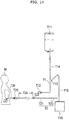
- Fig. 14 is a diagram for explaining a first tube T1 and a second tube T2 to be joined by the tube joining apparatus 1.
- Figs. 15 and 16 are diagrams for explaining an example of use of the tube joining apparatus 1.
- a tube joining set S in the present embodiment is configured as a medical apparatus that cuts by melting and joins an end portion of a tube on the side of a peritoneal dialysate bag T11 (corresponding to the "first tube T1") and an end portion of a tube on the side of a peritoneal catheter T26 of a patient (user M) used for peritoneal dialysis (corresponding to the "second tube T2").
- the tube joining set S includes a tube joining apparatus 1 capable of cutting by melting and joining the first tube T1 and the second tube T2, and a wafer cassette WC including a plurality of wafers WF (corresponding to "plate-shaped cutting members" used for cutting by melting.
- the wafer cassette WC is inserted into the tube joining apparatus 1.
- Figs. 15(A) to 15(C) the first tube T1 and the second tube T2 placed side by side are pressed against each other to be flattened, and cut by melting by a heated wafer WF.
- Figs. 15(D) and 16(A) the positions of one side of the first tube T1 and one side of the second tube T2 cut are exchanged, and pressurized to be joined.
- the configurations of parts of the tube joining set S will be described.
- the tube joining apparatus 1 includes a housing 10 that houses parts of the tube joining apparatus 1, a clamp 20 that sandwiches and presses the first tube T1 and the second tube T2 against each other and flattens them for cutting by melting, and exchanges the positions of one side of the first tube and one side of the second tube after cutting, and an interlock 30 that locks the clamp 20 in a state of sandwiching the first tube T1 and the second tube T2 during cutting and joining. Further, as shown in Fig.
- the tube joining apparatus 1 includes a wafer cassette storage unit 40 that stores the wafer cassette WC inserted into the housing 10, and a wafer feed unit 50 that heats and feeds a wafer WF to a cutting position. Furthermore, as shown in Fig. 1 , the tube joining apparatus 1 includes an operation unit 60 that can accept a cutting and joining instruction etc. from the user M, a notification unit 70 that notifies the user M of necessary information, a power supply 80 capable of supplying power to the parts, and a controller 90 that performs centralized control of the operations of the parts.
- the housing 10 has a function of housing the parts of the tube joining apparatus 1.
- the housing 10 is formed by a case that is the combination of an upper part 11 having a substantially prismoid-shaped outer shape and a lower part 12 having a substantially quadrangular prism-shaped outer shape disposed below the upper part 11.
- an upper part 11 having a substantially prismoid-shaped outer shape
- a lower part 12 having a substantially quadrangular prism-shaped outer shape disposed below the upper part 11.
- the operation unit 60 is provided on the front side of a top surface of the upper part 11.
- a display 71 of the notification unit 70 described later is provided on the back side of the top surface of the upper part 11.
- the upper part 11 has an inclined surface 11f inclined toward a bottom surface 12a of the lower part 12 from the back side toward the front side between the operation unit 60 and the display 71.
- the inclined surface 11f is provided with a recess 11a into which a predetermined connector T12 connected to the first tube T1 can be fitted, and a recess 11b into which the fixed side X2 of the second tube T2 can be fitted. This allows the user to set the first tube T1 and the second tube T2 in proper positions without mistaking the disposed positions of the tubes T1 and T2.
- a hole 11g in which the clamp 20 can be fitted is provided in the top surface of the upper part 11.
- a cassette insertion hole 11c for inserting the wafer cassette WC and an ejection switch 11d for ejecting the wafer cassette WC inserted in the housing 10 are provided. If the user M pushes the ejection switch 11d with a finger when the wafer cassette WC has been inserted through the cassette insertion hole 11c, the wafer cassette WC can be ejected from the housing 10 through the cassette insertion hole 11c.
- a temperature sensor 11e capable of measuring the ambient temperature around the housing 10 is contained in the upper part 11. Heating time during which a wafer WF heats the first tube T1 and the second tube T2 can be adjusted, according to the ambient temperature measured by the temperature sensor 11e.
- the lower part 12 includes the flat bottom surface 12a and four legs 12b that are provided at the four corners of the bottom surface 12a and in contact with a placement place such as a table.
- the bottom surface 12a is provided with a plurality of through holes for facilitating the propagation of the sound of a speaker 72 of the notification unit 70 described later to the outside of the housing 10, a plurality of through holes for discharging heat and gas generated when the first tube T1 and the second tube T2 are cut by melting to the outside of the housing 10, etc. (not shown).
- a direction perpendicular to the placement surface FS is referred to as a "height direction Z" of the housing 10.
- the height direction Z is also a direction dz in which a lid 22 relatively moves toward or away from the housing 10.
- the housing 10 does not necessarily have to be placed on the flat placement surface FS.
- the clamp 20 has a function of holding the first tube T1 and the second tube T2 in a state of being placed side by side, a function of pressing the first tube T1 and the second tube T2 against each other to flatten them for cutting, and a function of exchanging the positions of one side of the first tube T1 and one side of the second tube T2 after cutting.
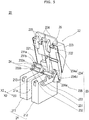
- the clamp 20 includes a pedestal 21 fixed to the bottom surface 12a of the housing 10, the lid 22 configured to be openable and closable by relatively moving toward and away from the pedestal 21, a tube holding part 23 provided on the pedestal 21 for holding the first tube T1 and the second tube T2, tube detection sensors 24 capable of detecting whether the first tube T1 and the second tube T2 are set, and a tube pressing part 25 that presses the first tube T1 and the second tube T2 against each other to flatten them as the lid 22 relatively moves toward the pedestal 13.
- the configurations of the parts of the clamp 20 will be described.
- the pedestal 21 includes a first pedestal 211 provided on the fixed side X2 of the first tube T1 and the second tube T2, and a second pedestal 212 provided on the exchanged side X1 of the first tube T1 and the second tube T2.
- a space 21a is provided between the first pedestal 211 and the second pedestal 212 along the extending direction of the first tube T1 and the second tube T2.
- the space 21a is a space through which a wafer WF passes when the wafer WF before use moves to the cutting position and when the wafer WF after use is sent out of the housing 10.
- the first pedestal 211 and the second pedestal 212 are each provided with an engaged part 213 on which an engaging claw 225 of the lid 22 described later is hooked to be fixed.
- the lid 22 includes a first clamp arm 221 provided rotatably with respect to the first pedestal 211, a second clamp arm 222 provided rotatably with respect to the second pedestal 212, a cover 223 covering the first clamp arm 221 and the second clamp arm 222, and grips 224 that are provided rotatably with respect to the clamp arms 221 and 222 and can be held by the user M.
- the clamp arms 221 and 222 are configured to be individually rotatable.
- the cover 223 integrally covers the first clamp arm 221 and the second clamp arm 222.
- the cover 223 covers the first pedestal 211, the second pedestal 212, and an area therebetween where cutting and joining is performed.
- the grips 224 have the engaging claws 225 engageable with the engaged parts 213 of the pedestal 21.
- the engaging claws 225 are engaged with the engaged parts 213 of the pedestal 21. This can suitably keep the clamp 20 sandwiching the tubes T1 and T2.
- the tube holding part 23 includes a first holding part 231 and a second holding part 232 that immovably hold the fixed sides X2 of the tubes T1 and T2, a third holding part 233 that movably holds the exchanged sides X1 of the tubes T1 and T2, a release part 234 that can switch the third holding part 233 from a holding state of holding the tubes T1 and T2 to a release state of releasing the holding, and a restoration part 235 that can switch the third holding part 233 from the release state to the holding state.
- the configurations of the parts of the tube holding part 23 will be described.
- the first holding part 231, the second holding part 232, and the third holding part 233 will be described.
- the first holding part 231 is fixed to a top surface of the first pedestal 211.
- the first holding part 231 includes a recessed first groove 231a into which the first tube T1 can be fitted, and a recessed second groove 231b into which the second tube T2 can be fitted.
- the first groove 231a and the second groove 231b are provided in a line in a direction tilted at an angle ⁇ with respect to the height direction Z of the housing 10 (oblique direction D1).
- the first tube T1 and the second tube T2 are held in the first holding part 231, placed side by side in the oblique direction D1.
- the first groove 231a disposed on the back side in the direction D1 in which the first tube T1 and the second tube T2 are placed side by side is disposed in a position higher than that of the second groove 231b in the height direction Z of the housing 10.
- the grooves 231a and 231b are recessed on the top surface side of the first holding part 231 along a direction D2 orthogonal to the oblique direction D1.
- the tubes T1 and T2 are set by being inserted from the direction D2 orthogonal to the direction D1 in which they are placed side by side. This allows the user M to easily insert and set the tubes T1 and T2 when the lid 22 is open.
- the second holding part 232 is fixed to a side surface of the first pedestal 211, adjacent to the first holding part 231.
- the second holding part 232 includes a recessed third groove 232a into which the first tube T1 can be fitted, and a recessed fourth groove 232b into which the second tube T2 can be fitted.
- the third groove 232a and the fourth groove 232b are provided in a line in the oblique direction D1.
- the third holding part 233 includes a base 233a rotatably provided at a side surface of the second pedestal 212, and a bent portion 233b bent from and continuous with the base 233a.
- the bent portion 233b is provided with a recessed fifth groove 233c into which the exchanged side X1 of the first tube T1 can be fitted, and a recessed sixth groove 233d into which the exchanged side X1 of the second tube T2 can be fitted.
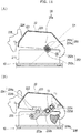
- the third holding part 233 is configured to be movable between a position shown in Fig. 9(B) in which the fifth groove 233c and the sixth groove 233d are in a line along the oblique direction D1, and the third holding part 233 can hold the tubes T1 and T2 with the first holding part 231 and the second holding part 232 (referred to as a "holding position P0"), and a position shown in Fig. 12(B) in which the third holding part 233 has released holding (referred to as a "release position P1").
- the angle ⁇ formed between the oblique direction D1 and the height direction Z of the housing 10 is 45 degrees. That is, the holding parts 231, 232, and 233 hold the first tube T1 and the second tube T2 such that an imaginary line (indicated by a chain line in the figure) connecting the axis of the first tube T1 and the axis of the second tube T2 forms an angle of 45 degrees with respect to the height direction Z.
- the angle ⁇ is not limited to a particular angle as long as it is larger than 0 degrees and smaller than 90 degrees.
- the holding parts 231, 232, and 233 hold the tubes T1 and T2 individually in a state of being placed side by side in the oblique direction D1 with respect to the height direction Z of the housing 10.
- the user M sits on a chair or the like and uses the tube joining apparatus 1 placed on a table or the like, looking into it from obliquely above.
- the user M can set the tubes T1 and T2 in the holding parts 231, 232, and 233 without changing his or her posture. Further, the user M can easily visually check whether the set tubes T1 and T2 are properly set (the presence or absence of a twist or the like).
- the grooves 231b, 232b, and 233d and the second tube T2 disposed on the lower side are hidden behind the grooves 231a, 232a, and 233c and the first tube T1 disposed on the upper side (the lid 22 side) and difficult to check visually, since the eyes of the user M are located obliquely above the tube joining apparatus 1.
- the user M needs to take the trouble to stoop down to look into the tube joining apparatus 1 to check whether the tubes T1 and T2 are properly set.
- the grooves 231a, 232a, and 233c and the first tube T1 disposed on the back side are hidden behind the grooves 231b, 232b, and 233d and the second tube T2 disposed on the front side and difficult to check visually, since the eyes of the user M are located obliquely above the tube joining apparatus 1.
- the user M needs to take the trouble to bend forward to the back side to look into the tube joining apparatus 1 to check whether the tubes T1 and T2 are properly set.
- the angle ⁇ is preferably 30 degrees or more and less than 90 degrees, for example.
- the release part 234 includes a flat surface 234a continuous with a side surface of the second clamp arm 222, and a protrusion 234b protruding from the base 233a of the third holding part 233 toward the flat surface 234a of the second clamp arm 222.
- the protrusion 234b provided at the third holding part 233 comes into contact with the flat surface 234a provided at the lid 22 as the lid 22 relatively moves toward the housing 10.
- the protrusion 234b comes into contact with the flat surface 234a.
- the third holding part 233 is pushed down in a direction D3 to move away from the lid 22, releasing the holding of the tubes T1 and T2.
- the release part 234 is configured to retract the third holding part 233 from the holding position P0 to the release position P1 as the lid 22 relatively moves toward the housing 10.
- the restoration part 235 includes a cam 235a that can push up the third holding part 233 in conjunction with the relative movement of the second clamp arm 222 of the lid 22 away from the housing 10.
- the cam 235a has a substantially fan-shaped outer shape in an arrow view from the direction of the side of the housing 10.
- the cam 235a is fixed near a rotating portion of the second clamp arm 222.
- the cam 235a also rotates in conjunction with the rotation of the second clamp arm 222.
- a curved surface of the cam 235a is in contact with a bottom surface of the third holding part 233, keeping the third holding part 233 in the holding position P0.
- Fig. 10(B) when the lid 22 is relatively moved toward the housing 10, the curved surface of the cam 235a moves away from the third holding part 233 before the protrusion 234b of the release part 234 comes into contact with the flat surface 234a.
- the cam 235a does not prevent the third holding part 233 from being moved from the holding position P0 to the release position P1 by the release part 234.
- the cam 235a comes into contact with the third holding part 233 to push up the third holding part 233.
- the third holding part 233 is returned from the release position P1 to the holding position P0.
- the third holding part 233 is configured to be movable between the holding position P0 and the release position P1 by the release part 234 and the restoration part 235.
- the third holding part 233 does not interfere with a position exchange operation for exchanging the positions of one side of the first tube T1 and one side of the second tube T2 after cutting performed with the lid 22 closed.
- the release part 234 retracts the third holding part 233 from the holding position P0 to the release position P1 after the tube pressing part 25 described later sandwiches the first tube T1 and the second tube T2.
- the tube pressing part 25 can sandwich the first tube T1 and the second tube T2 with the exchanged sides X1 of the first tube T1 and the second tube T2 held in proper positions by the third holding part 233.
- the tube detection sensors 24 are provided in the third groove 232a and the fourth groove 232b of the second holding part 232.
- the tube detection sensors 24 have a function of detecting whether the tubes T1 and T2 are set in the grooves 232a and 232b of the second holding part 232.
- the configuration of the tube detection sensors 24 will be described, using the tube detection sensor 24 set in the third groove 232a as an example.
- the tube detection sensor 24 includes a pin 241 that can protrude from a hole provided in the third groove 232a, a base 242 that supports the pin 241, a magnet 243 attached to the base 242, a Hall element 244 that can detect the magnetic force of the magnet 243, and a biasing member 245 that applies a biasing force to the pin 241 in a direction to protrude from the hole.
- the biasing member 245 is formed by a spring.
- the biasing member 245 is not limited to a particular configuration as long as it can apply a biasing force to the pin 241 in a direction to protrude from the hole.
- the tube detection sensor 24 can detect whether the first tube T1 is set in the third groove 232a and whether the first tube T1 is pushed into the back of the third groove 232a, based on the strength of the magnetic force of the magnet 243 that can be detected by the Hall element 244.
- the tube detection sensors 24 may be provided in the first holding part 231 or the third holding part 233.
- the tube pressing part 25 includes a fixed-side pressing part 25a that presses the fixed side X2 of the first tube T1 and the fixed side X2 of the second tube T2 against each other, and the movable-side pressing part 25b that presses the exchanged side X1 of the first tube T1 and the exchanged side X1 of the second tube T2 against each other, as the lid 22 relatively moves toward the housing 10.
- the configurations of the parts of the tube pressing part 25 will be described.
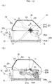
- the fixed-side pressing part 25a includes a lid-side pressing part 251 provided at the first clamp arm 221, and a housing-side pressing part 252 provided at the first pedestal 211. As shown in Fig. 12(A) , when the lid 22 is closed, the lid-side pressing part 251 and the housing-side pressing part 252 are integrated, and have a function of keeping the first tube T1 and the second tube T2 pressed against each other and flattened, and a function of holding the first tube T1 and the second tube T2 in positions during cutting and joining.
- the configurations of the parts of the fixed-side pressing part 25a will be described.
- the lid-side pressing part 251 is protruded from a side surface of the first clamp arm 221 toward the second clamp arm 222.
- the lid-side pressing part 251 includes a lid-side pressing portion 251a that applies a pressing force to the first tube T1 and the second tube T2 from the lid 22 side, and a lid-side protruding portion 251b that protrudes from the lid-side pressing portion 251a toward the housing 10, when the lid 22 is closed.
- the lid-side pressing portion 251a is formed by a flat surface orthogonal to the oblique direction D1 when the lid 22 is closed. When the lid 22 is closed, the lid-side pressing portion 251a applies a pressing force to the first tube T1 in a direction to move toward the second tube T2 (a direction along the oblique direction D1).
- the lid-side protruding portion 251b protrudes from the lid-side pressing portion 251a in a rotation direction R when the lid 22 is closed.
- the lid-side protruding portion 251b can cover the first tube T1 and the second tube T2 to enclose them in conjunction with the relative movement of the lid 22 toward the housing 10.
- the lid-side protruding portion 251b extends along the oblique direction D1 beyond a contact position C between the first tube T1 and the second tube T2 flattened, and is in contact with an end portion of a housing-side pressing portion 252a described later.
- the surfaces of the lid-side pressing portion 251a and the lid-side protruding portion 251b on the side facing the tubes T1 and T2 are of an L shape in an arrow view from the extending direction of the first tube T1 and the second tube T2.
- the housing-side pressing part 252 is protruded from a side surface of the first pedestal 211 toward the second pedestal 212.
- the housing-side pressing part 252 includes the housing-side pressing portion 252a that applies a pressing force to the first tube T1 and the second tube T2 from the housing 10 side, and a housing-side protruding portion 252b protruding from the housing-side pressing portion 252a toward the lid 22, when the lid 22 is closed.
- the housing-side pressing portion 252a is formed by a flat surface orthogonal to the oblique direction D1 when the lid 22 is closed.
- the housing-side pressing portion 252a applies a pressing force to the second tube T2 in a direction to move toward the first tube T1 (a direction along the oblique direction D1).
- the directions of the pressing forces applied to the tubes T1 and T2 by the housing-side pressing portion 252a and the lid-side pressing portion 251a described above coincide with the direction D1 in which the first tube T1 and the second tube T2 are placed side by side.
- the housing-side pressing portion 252a and the lid-side pressing portion 251a can press the tubes T1 and T2 against each other and flatten them only by slightly moving them closer from the positions in which they are set in the tube holding part 23.
- the clamp 20 it is not necessary to largely move the tubes T1 and T2 set by the user M, so that the user M can be given a sense of security that the displacement of the tubes T1 and T2 is unlikely to occur.
- the housing-side protruding portion 252b protrudes from the housing-side pressing portion 252a, opposite the above-described lid-side protruding portion 251b.
- the housing-side protruding portion 252b extends along the oblique direction D1 beyond the contact position C between the first tube T1 and the second tube T2 flattened, and is in contact with an end portion of the lid-side pressing portion 251a. Consequently, when the lid 22 is closed, the housing-side protruding portion 252b and the lid-side protruding portion 251b are provided in positions opposite to each other, and can surround the peripheral surface of the first tube T1 and the peripheral surface of the second tube T2.
- the surfaces of the housing-side pressing portion 252a and the housing-side protruding portion 252b on the side facing the tubes T1 and T2 are of an L shape in an arrow view from the extending direction of the first tube T1 and the second tube T2.
- the lid-side pressing portion 251a comes into contact with the first tube T1, and the first tube T1 and the second tube T2 are sandwiched between the lid-side pressing portion 251a and the housing-side pressing portion 252a.
- the lid-side pressing portion 251a and the housing-side pressing portion 252a press the first tube T1 and the second tube T2 against each other along the oblique direction D1, flattening them.
- the lid-side protruding portion 251b brings the first tube T1 and the second tube T2 closer to the housing-side protruding portion 252b, enclosing the first tube T1 and the second tube T2 with the housing-side protruding portion 252b.
- This can suitably prevent the displacement of the first tube T1 and the second tube T2 in a direction intersecting the direction D1 in which the first tube T1 and the second tube T2 are placed side by side.
- the movable-side pressing part 25b includes a lid-side pressing part 253 protruded from a side surface of the second clamp arm 222 toward the first clamp arm 221, and a housing-side pressing part 254 protruded from a side surface of the second pedestal 212 toward the first pedestal 211.
- the movable-side pressing part 25b further includes a lid-side clamp member 255 continuous with the lid-side pressing part 253 and extending along the entire length of the second clamp arm 222 in the width direction, a housing-side clamp member 256 extending along the entire length of the second pedestal 212 in the width direction, and a drive unit 257 that exchanges the positions of one side of the first tube T1 and one side of the second tube T2 by rotating 180 degrees the lid-side clamp member 255 and the housing-side clamp member 256 integrated.
- a lid-side clamp member 255 continuous with the lid-side pressing part 253 and extending along the entire length of the second clamp arm 222 in the width direction
- a housing-side clamp member 256 extending along the entire length of the second pedestal 212 in the width direction
- a drive unit 257 that exchanges the positions of one side of the first tube T1 and one side of the second tube T2 by rotating 180 degrees the lid-side clamp member 255 and the housing-side clamp member 256 integrated.
- the configuration of the lid-side pressing part 253 of the movable-side pressing part 25b is similar to the configuration of the lid-side pressing part 251 of the fixed-side pressing part 25a described above, and thus will not be described.
- the configuration of the housing-side pressing part 254 of the movable-side pressing part 25b is similar to the configuration of the housing-side pressing part 252 of the fixed-side pressing part 25a described above, and thus will not be described.
- the lid-side clamp member 255 includes a recessed groove 255a extending along the entire length of the second clamp arm 222 in the width direction.
- the housing-side clamp member 256 includes a recessed groove 256a extending along the entire length of the second pedestal 212 in the width direction. When the lid 22 is closed, the first tube T1 and the second tube T2 are sandwiched between the grooves 255a and 256a.
- the drive unit 257 includes a first gear 257a provided around the lid-side clamp member 255 and the housing-side clamp member 256 integrated when the lid 22 is closed, a second gear 257b engaged with the first gear 257a, and a motor 257c connected to a rotating shaft of the second gear 257b.
- the controller 90 described later drives the motor 257c at a stage where cutting is completed
- the second gear 257b rotates.
- the first gear 257a rotates with the rotation of the second gear 257b, so that the lid-side clamp member 255 and the housing-side clamp member 256 integrated also rotate with the first gear 257a.
- the lid-side pressing part 253 and the housing-side pressing part 254 continuous with the lid-side clamp member 255 and the housing-side clamp member 256 also rotate.
- Figs. 15(D) and 16(A) the positions of the exchanged side X1 of the first tube T1 and the exchanged side X1 of the second tube T2 after cutting can be exchanged.
- the interlock 30 has a function of locking the clamp 20 in a state of sandwiching the first tube T1 and the second tube T2 during cutting and joining.
- the interlock 30 is formed by an electromagnetically driven solenoid rod 31.
- the solenoid rod 31 moves upward in the height direction Z of the housing 10 according to a command transmitted from the controller 90, and comes into contact with a front-side surface of the engaging claw 225 of the lid 22, keeping the grips 224 from rotating with respect to the clamp arms 221 and 222.
- the wafer cassette storage unit 40 has a function of storing the wafer cassette WC inserted into the housing 10, and a function of detecting the remaining quantity of wafers WF in the wafer cassette WC.
- the wafer cassette storage unit 40 includes a storage for storing the wafer cassette WC inserted through the cassette insertion hole 11c, and a wafer remaining quantity detection sensor that can detect the remaining quantity of wafers WF in the wafer cassette WC (not shown).
- the wafer remaining quantity detection sensor can be formed, for example, by a known photosensor.
- the wafer feed unit 50 has a function of feeding a wafer WF to the cutting position, a function of heating a wafer WF for cutting, a function of cooling a used wafer WF, and a function of sending a used wafer WF to the outside of the housing 10.
- the wafer feed unit 50 includes a drive unit that can feed a wafer WF from the wafer cassette WC in the wafer cassette storage unit 40 to the cutting position, and can send a used wafer WF to the outside of the housing 10 through the space 21a between the first pedestal 211 and the second pedestal 212, a heater that can heat a wafer WF for cutting, and a fan that can cool a used wafer WF (not shown).
- the operation unit 60 has a function of accepting instructions from the user M to the tube joining apparatus 1.
- the operation unit 60 is provided with a plurality of switches 61.
- the switches 61 By pressing the switches 61, the user M can make an instruction to the tube joining apparatus 1 to switch the power supply of the tube joining apparatus 1 on or off, an instruction to start cutting and joining, etc.
- the notification unit 70 has a function of notifying the user M of necessary information.
- the notification unit 70 includes the display 71 that displays necessary information for the user M, and the speaker 72 that notifies the user M of necessary information by voice.
- the notification unit 70 is configured to be able to notify the user M that the power is ON, that charging is in progress, that cutting and joining is in progress, that the used wafer WF can be taken out, that the tube joining apparatus 1 is in failure, etc. Further, the notification unit 70 is configured to be able to notify the user M that the lid 22 is not closed when cutting and joining is performed, that the wafer cassette WC needs to be replaced, that the wafer WF is defective, that charging is required, that the temperature is inappropriate, etc.
- the power supply 80 has a function of supplying power to the parts of the tube joining apparatus 1.
- the power supply 80 includes a battery 81 that can supply power to the parts, and a charger 82 for charging the battery 81.
- the controller 90 has a function of performing centralized control of the parts of the tube joining apparatus 1.
- the controller 90 includes a CPU such as a microcomputer, ROM that stores control programs of the entire apparatus executed by the CPU and various data, and RAM that temporarily stores measurement data and various data as a work area.
- a CPU such as a microcomputer
- ROM that stores control programs of the entire apparatus executed by the CPU and various data
- RAM that temporarily stores measurement data and various data as a work area.
- the controller 90 is electrically connected to the power supply 80, and receives power supply from the power supply 80.
- the controller 90 is electrically connected to the operation unit 60, and is configured to be able to control the operations of the parts in response to instructions from the user M.
- the controller 90 is electrically connected to the notification unit 70, and is configured to be able to notify the user M of necessary information.
- the controller 90 is electrically connected to the tube detection sensors 24, the interlock 30, and the temperature sensor 11e. For example, when the controller 90 obtains information from the tube detection sensors 24 that the first tube T1 and the second tube T2 are not properly set, the controller 90 can notify the information via the notification unit 70.
- the controller 90 is configured to keep the lid 22 in the closed position with the interlock 30 during cutting and joining.
- the controller 90 is configured to adjust time to heat the first tube T1 and the second tube T2 by the wafer WF during cutting, based on the ambient temperature of the housing 10 measured by the temperature sensor 11e.
- the controller 90 is electrically connected to the wafer cassette storage unit 40 and the wafer feed unit 50, and is configured to be able to control their operations.
- the controller 90 is electrically connected to the motor 257c of the movable-side pressing part 25b, and controls the position exchange operation of the movable-side pressing part 25b.
- the wafer cassette WC stores a plurality of wafers WF.
- the wafer cassette WC is inserted and taken out through the cassette insertion hole 11c of the tube joining apparatus 1.
- a used wafer WF is taken out of the housing 10 from the space 21a between the first pedestal 211 and the second pedestal 212.
- the first tube T1 is formed by a tube on the peritoneal dialysate bag T11 side.
- the predetermined connector T12 is attached to the distal end of the first tube T1.
- the opposite end of the first tube T1 is connected to a dialysate tube T14 of the dialysate bag T11 via a branch tube T13.
- the first tube T1 is connected to a drain tube T16 of a drain bag T15 via the branch tube T13.
- the second tube T2 is formed by a tube on the side of the peritoneal catheter T26 of the user M used for peritoneal dialysis.
- the second tube T2 includes an extension tube T21 and a protection tube T22.
- the extension tube T21 is connected to the peritoneal catheter T26 via a connecting tube T23, a silicone tube T24, and a catheter joint T25.
- One end portion of the peritoneal catheter T26 is inserted into the abdominal cavity of the user M.
- the first tube T1 and the second tube T2 are formed by polyvinyl chloride tubes.
- the material of the first tube T1 and the second tube T2 is not limited to that, and may be any as long as it allows the first and second tubes T1 and T2 to be joined to each other by cutting by melting and pressurization.
- the first tube T1 and the second tube T2 may be of different materials.
- the user M inserts the wafer cassette WC into the cassette insertion hole 11c of the tube joining apparatus 1.
- the user M opens the lid 22 of the tube joining apparatus 1.
- the user M sets the first tube T1 and the second tube T2 in the predetermined positions of the holding parts 231, 232, and 233.
- the user M performs an operation to close the lid 22 (an operation to relatively move the lid 22 toward the housing 10).
- the tube pressing part 25 sandwiches the first tube T1 and the second tube T2.
- the protrusion 234b of the third holding part 233 of the tube holding part 23 comes into contact with the flat surface 234a of the lid 22.
- the lid 22 is further pushed down from the state of Fig. 11(B) to completely close the lid 22, as shown in Fig.
- the third holding part 233 retracts from the holding position P0 to the release position P1, releasing the holding of the tubes T1 and T2.
- the lid 22 being closed, outer peripheral portions of the cut parts of the first tube T1 and the second tube T2 are covered by the cover 223 and isolated from the outside. This allows the cutting and joining operation to be performed under aseptic conditions.
- the user M operates the operation unit 60 to instruct the tube joining apparatus 1 to start cutting and joining.
- the controller 90 starts the cutting and joining operation.
- the controller 90 activates the interlock 30 to lock the lid 22 in the closed position.
- the controller 90 controls the operation of the wafer feed unit 50 to perform a cutting operation. Specifically, as shown in Fig. 15(C) , a heated wafer WF is fed from the wafer cassette WC, and passes through a space between the fixed-side pressing part 25a and the movable-side pressing part 25b, cutting the first tube T1 and the second tube T2 by melting.
- the controller 90 drives the motor 257c of the movable-side pressing part 25b to exchange the positions of the exchanged side X1 of the first tube T1 and the exchanged side X1 of the second tube T2 as shown in Fig. 15(D) .
- the ends of the first tube T1 and the second tube T2 exchanged in positions are brought closer to each other and pressure-joined.
- controller 90 unlocks the interlock 30.
- the user M performs an operation to open the lid 22 and removes the tubes T1 and T2 from the tube joining apparatus 1.
- the first tube T1 and the second tube T2 are joined in an X shape as shown in Fig. 16(B) .
- the user M performs an operation to separate the first tube T1 and the second tube T2 joined, into two tubes. Consequently, as shown in Fig.
- a tube with the fixed side X2 of the first tube T1 (the side connected to the connector T12) joined to the exchanged side X1 of the second tube T2 (the side of the end to which nothing is connected), and a tube with the exchanged side X1 of the first tube T1 (the side connected to the branch tube T13) joined to the fixed side X2 of the second tube T2 (the side connected to the peritoneal catheter T26) are obtained.
- the tube joining apparatus 1 includes the housing 10, the lid 22 relatively movable toward and away from the housing 10, the tube holding part 23 that holds the first tube T1 and the second tube T2 individually in the state of being placed side by side in the oblique direction D1 with respect to the height direction Z of the housing 10, and the tube pressing part 25 that presses the first tube T1 and the second tube T2 against each other as the lid 22 relatively moves toward the housing 10.
- the user M can set the tubes T1 and T2 individually while visually checking the disposed positions of the tubes T1 and T2 in the tube holding part 23, and can suitably visually check whether the tubes are set properly.
- the tube holding part 23 holds the first tube T1 disposed on the back side in the direction D1 in which the first tube T1 and the second tube T2 are placed side by side, in a position higher than that of the second tube T2 in the height direction Z of the housing 10. Therefore, the user M can suitably visually check the first tube T1 set on the back side.
- the tube holding part 23 includes the recessed grooves 231a, 232a, and 233c into which the first tube T1 can be fitted, and the recessed grooves 231b, 232b, and 233d into which the second tube T2 can be fitted. This allows the user M to set the tubes T1 and T2 individually by inserting them into the grooves.
- the tube pressing part 25 presses the first tube T1 and the second tube T2 against each other along the oblique direction D1 in which the first tube T1 and the second tube T2 are placed side by side, as the lid 22 relatively moves toward the housing 10. This allows the tubes T1 and T2 set by the user M to be flattened only by slightly moving them closer. Since there is no need to largely move the set tubes T1 and T2, it is possible to give the user M a sense of security that the first tube T1 and the second tube T2 can be pressed against each other by closing the lid 22.
- the tube holding part 23 holds the first tube T1 and the second tube T2 such that the imaginary line connecting the axis of the first tube T1 and the axis of the second tube T2 forms an angle of 45° with respect to the height direction Z of the housing 10. This allows the first tube T1 and the second tube T2 to be set in the positions where the user M can more easily visually check both the first tube T1 and the second tube T2.
- the above embodiment has described a form in which the first tube is a dialysate tube connected to a peritoneal dialysate bag via a branch tube, and the second tube is a tube on the side of a peritoneal catheter of a patient used for peritoneal dialysis.
- the tubes are not limited to particular ones as long as they are tubes exchanged in end positions after cutting and pressure-joined.
- the first tube may be a tube that is connected to a plurality of peritoneal dialysate bags and drain tanks and connected to an apparatus that automatically performs peritoneal fluid dialysis.
- the first tube and the second tube are not limited to tubes used for peritoneal dialysis.
- the first tube is disposed on the back side and the second tube is disposed on the front side, but the first tube may be disposed on the front side and the second tube may be disposed on the back side.
- the above-described embodiment has described a form in which the legs provided at the bottom surface of the housing are in contact with a placement place such as a table.
- the bottom surface of the housing may not be provided with legs, and the bottom surface may be in direct contact with a placement place such as a table.
- the above-described embodiment has described a form in which the tube holding part includes the first holding part, the second holding part, and the third holding part.
- the number of holding parts of the tube holding part is not limited to a particular number.
Landscapes
- Engineering & Computer Science (AREA)
- Mechanical Engineering (AREA)
- Health & Medical Sciences (AREA)
- Heart & Thoracic Surgery (AREA)
- Veterinary Medicine (AREA)
- General Health & Medical Sciences (AREA)
- Public Health (AREA)
- Animal Behavior & Ethology (AREA)
- Anesthesiology (AREA)
- Biomedical Technology (AREA)
- Hematology (AREA)
- Life Sciences & Earth Sciences (AREA)
- Pulmonology (AREA)
- Toxicology (AREA)
- Thermal Sciences (AREA)
- Physics & Mathematics (AREA)
- Infusion, Injection, And Reservoir Apparatuses (AREA)
- External Artificial Organs (AREA)
- Emergency Medicine (AREA)
- Urology & Nephrology (AREA)
- Vascular Medicine (AREA)
Abstract
Description
- The present invention relates to a tube joining apparatus used to join tubes.
- As a technique for joining resin tubes or the like together, there is a conventionally known joining method in which end portions of resin tubes are cut by melting, and the cut ends are pressed against each other to be pressure-joined. This technique is widely used in various industrial fields. As an example, its application to medical technology such as peritoneal dialysis has been attempted.
- Peritoneal dialysis is a method in which a tube (catheter) implanted in the abdominal cavity of a patient is used to introduce a predetermined dialysate into the body, and then water and waste products transferred into the dialysate through the peritoneum is removed out of the body. When the dialysate is introduced into the body, the tube implanted in the patient is liquid-tightly joined to a tube of a bag containing the dialysate. When the dialysate is drained from the body, the tube implanted in the patient is liquid-tightly joined to a tube of a drain bag.
- Since one tube to be joined is implanted in the abdominal cavity of the patient as described above, close attention must be paid to a joining operation so that the tubes are not contaminated during the operation. In view of this point, as described in
Patent Literature 1, for example, a tube joining apparatus has been developed which enables cutting of two resin tubes by melting and automatically joining them under aseptic conditions. This apparatus exchanges the positions of cut end portions of the two tubes and joins the tubes, and thus ends concern over bacterial contamination during joining, and can keep a dialysate or the like in the tubes and a bag sterile. In this apparatus, the two tubes are placed on each other in close contact in a vertical direction (height direction) of the apparatus, and a heated plate-shaped metal wafer is moved toward the tubes to cut them by melting. - Patent Literature 1:
JP 2013-146354 A - When using the above-described tube joining apparatus, a user such as a patient manually sets tubes to be joined in the tube joining apparatus, placing them on each other in the height direction of the apparatus. At this time, the user may mishandle the tubes, placing the tubes on each other in a twisted state or placing them on each other in three layers because the tubes themselves have flexibility. If the apparatus is caused to perform a cutting and joining operation with the tubes set like this, the tubes are joined to each other, but a joining failure such as a hole formed in a joined portion occurs.
- The present invention has been made in view of the above problem, and its object is to provide a tube joining apparatus that allows a user to easily and properly set tubes to be joined, and can prevent occurrence of joining failures due to tube setting errors.
- A tube joining apparatus according to the present invention that solves the above problem is a tube joining apparatus that melts and cuts an end portion of a first tube and an end portion of a second tube with a heated plate-shaped cutting member, and then exchanges positions of the cut end portion of the first tube and the cut end portion of the second tube and joins the tubes under aseptic conditions. The tube joining apparatus includes a housing, a lid relatively movable toward and away from the housing, a tube holding part that holds the first tube and the second tube individually in a state of being placed side by side in an oblique direction with respect to a height direction of the housing, and a tube pressing part that presses the first tube and the second tube against each other as the lid relatively moves toward the housing.
- According to the tube joining apparatus of the present invention, the tube holding part holds the first tube and the second tube individually in the state of being placed side by side in the oblique direction. This allows a user to set the tubes individually while visually checking the disposed positions of the tubes in the tube holding part, and suitably visually check whether the set tubes are set properly. Thus, there is no need to place the tubes on each other in setting, and it can be suitably visually checked whether the tubes are properly set in the tube holding part. Consequently, it is possible to suitably prevent occurrence of setting errors of the tubes such as twists in the tubes.
- Brief Description of Drawings
-
-
Fig. 1 is a schematic perspective view showing a tube joining apparatus with a lid open according to an embodiment of the present invention. -
Fig. 2 is a schematic perspective view showing the tube joining apparatus with the lid closed. -
Fig. 3 is a schematic perspective view showing an arrangement example of components disposed in a housing of the tube joining apparatus when the lid is closed. -
Fig. 4 is a schematic plan view of the tube joining apparatus with the lid open,Fig. 4(A) is a diagram before a first tube and a second tube are set, andFig. 4(B) is a diagram when the first tube and the second tube are set. -
Fig. 5 is an enlarged schematic perspective view showing a clamp included in the tube joining apparatus. -
Fig. 6 is a diagram for explaining tube detection sensors provided at the clamp. -
Fig. 7 is an enlarged schematic perspective view showing a tube pressing part included in the clamp. -
Fig. 8 is a schematic diagram showing a drive unit included in the tube pressing part. -
Fig. 9 is a diagram showing the tube joining apparatus with the lid open,Fig. 9(A) is a cross-sectional view taken alongline 9A-9A inFig. 4(B) , andFig. 9(B) is a cross-sectional view taken alongline 9B-9B inFig. 4(B) . -
Fig. 10 is a diagram showing the tube joining apparatus when the lid is being moved toward the housing. -
Fig. 11 is a diagram showing the tube joining apparatus when the lid is being moved toward the housing. -
Fig. 12 is a diagram showing the tube joining apparatus with the lid closed. -
Fig. 13 is a block diagram showing a control system of the tube joining apparatus. -
Fig. 14 is a diagram schematically showing the first tube and the second tube to be cut and joined by the tube joining apparatus. -
Fig. 15 is a diagram schematically showing steps of a cutting and position exchange operation by the tube joining apparatus. -
Fig. 16 is a diagram schematically showing steps of a joining and removal operation by the tube joining apparatus. - An embodiment of the present invention will be described below with reference to the drawings. Dimensional ratios in the drawings are exaggerated for the convenience of illustration, and may differ from actual ratios.
-
Figs. 1 to 3 are diagrams for explaining the overall configuration of atube joining apparatus 1 according to the present embodiment.Figs. 4 to 13 are diagrams for explaining the configurations of parts of thetube joining apparatus 1.Fig. 14 is a diagram for explaining a first tube T1 and a second tube T2 to be joined by thetube joining apparatus 1.Figs. 15 and16 are diagrams for explaining an example of use of thetube joining apparatus 1. - As shown in
Fig. 14 , a tube joining set S in the present embodiment is configured as a medical apparatus that cuts by melting and joins an end portion of a tube on the side of a peritoneal dialysate bag T11 (corresponding to the "first tube T1") and an end portion of a tube on the side of a peritoneal catheter T26 of a patient (user M) used for peritoneal dialysis (corresponding to the "second tube T2"). - As shown in
Fig. 1 , the tube joining set S includes atube joining apparatus 1 capable of cutting by melting and joining the first tube T1 and the second tube T2, and a wafer cassette WC including a plurality of wafers WF (corresponding to "plate-shaped cutting members" used for cutting by melting. The wafer cassette WC is inserted into thetube joining apparatus 1. As shown inFigs. 15(A) to 15(C) , the first tube T1 and the second tube T2 placed side by side are pressed against each other to be flattened, and cut by melting by a heated wafer WF. Thereafter, as shown inFigs. 15(D) and16(A) , the positions of one side of the first tube T1 and one side of the second tube T2 cut are exchanged, and pressurized to be joined. Hereinafter, the configurations of parts of the tube joining set S will be described. - An overview of the
tube joining apparatus 1 will be provided. As shown inFig. 1 , thetube joining apparatus 1 includes ahousing 10 that houses parts of thetube joining apparatus 1, aclamp 20 that sandwiches and presses the first tube T1 and the second tube T2 against each other and flattens them for cutting by melting, and exchanges the positions of one side of the first tube and one side of the second tube after cutting, and aninterlock 30 that locks theclamp 20 in a state of sandwiching the first tube T1 and the second tube T2 during cutting and joining. Further, as shown inFig. 3 , thetube joining apparatus 1 includes a wafercassette storage unit 40 that stores the wafer cassette WC inserted into thehousing 10, and awafer feed unit 50 that heats and feeds a wafer WF to a cutting position. Furthermore, as shown inFig. 1 , thetube joining apparatus 1 includes anoperation unit 60 that can accept a cutting and joining instruction etc. from the user M, anotification unit 70 that notifies the user M of necessary information, apower supply 80 capable of supplying power to the parts, and acontroller 90 that performs centralized control of the operations of the parts. - As shown in
Figs. 1 and4 , with a cutting position X0 of the tubes T1 and T2 as a boundary in an extending direction of the tubes T1 and T2, the side on which the positions of the tubes T1 and T2 are exchanged after cutting is referred to as an "exchanged side X1", and the opposite side as a "fixed side X2". Hereinafter, the configurations of the parts of thetube joining apparatus 1 will be described in detail. - The
housing 10 has a function of housing the parts of thetube joining apparatus 1. - As shown in
Fig. 1 , thehousing 10 is formed by a case that is the combination of anupper part 11 having a substantially prismoid-shaped outer shape and alower part 12 having a substantially quadrangular prism-shaped outer shape disposed below theupper part 11. Hereinafter, the configurations of the parts of thehousing 10 will be described. - The
operation unit 60 is provided on the front side of a top surface of theupper part 11. Adisplay 71 of thenotification unit 70 described later is provided on the back side of the top surface of theupper part 11. - The
upper part 11 has aninclined surface 11f inclined toward abottom surface 12a of thelower part 12 from the back side toward the front side between theoperation unit 60 and thedisplay 71. As shown inFigs. 4(A) and 4(B) , theinclined surface 11f is provided with arecess 11a into which a predetermined connector T12 connected to the first tube T1 can be fitted, and arecess 11b into which the fixed side X2 of the second tube T2 can be fitted. This allows the user to set the first tube T1 and the second tube T2 in proper positions without mistaking the disposed positions of the tubes T1 and T2. - As shown in
Fig. 1 , ahole 11g in which theclamp 20 can be fitted is provided in the top surface of theupper part 11. - In a side surface of the
upper part 11, acassette insertion hole 11c for inserting the wafer cassette WC and anejection switch 11d for ejecting the wafer cassette WC inserted in thehousing 10 are provided. If the user M pushes theejection switch 11d with a finger when the wafer cassette WC has been inserted through thecassette insertion hole 11c, the wafer cassette WC can be ejected from thehousing 10 through thecassette insertion hole 11c. - As shown in
Fig. 3 , atemperature sensor 11e capable of measuring the ambient temperature around thehousing 10 is contained in theupper part 11. Heating time during which a wafer WF heats the first tube T1 and the second tube T2 can be adjusted, according to the ambient temperature measured by thetemperature sensor 11e. - As shown in
Fig. 1 , thelower part 12 includes theflat bottom surface 12a and fourlegs 12b that are provided at the four corners of thebottom surface 12a and in contact with a placement place such as a table. Thebottom surface 12a is provided with a plurality of through holes for facilitating the propagation of the sound of aspeaker 72 of thenotification unit 70 described later to the outside of thehousing 10, a plurality of through holes for discharging heat and gas generated when the first tube T1 and the second tube T2 are cut by melting to the outside of thehousing 10, etc. (not shown). - In the description, when it is assumed that the
housing 10 is placed on a flat placement surface FS (e.g., a table) as shown inFig. 9 , a direction perpendicular to the placement surface FS is referred to as a "height direction Z" of thehousing 10. In the present embodiment, the height direction Z is also a direction dz in which alid 22 relatively moves toward or away from thehousing 10. In actual use, thehousing 10 does not necessarily have to be placed on the flat placement surface FS. - The
clamp 20 has a function of holding the first tube T1 and the second tube T2 in a state of being placed side by side, a function of pressing the first tube T1 and the second tube T2 against each other to flatten them for cutting, and a function of exchanging the positions of one side of the first tube T1 and one side of the second tube T2 after cutting. - As shown in
Fig. 5 , theclamp 20 includes apedestal 21 fixed to thebottom surface 12a of thehousing 10, thelid 22 configured to be openable and closable by relatively moving toward and away from thepedestal 21, atube holding part 23 provided on thepedestal 21 for holding the first tube T1 and the second tube T2,tube detection sensors 24 capable of detecting whether the first tube T1 and the second tube T2 are set, and atube pressing part 25 that presses the first tube T1 and the second tube T2 against each other to flatten them as thelid 22 relatively moves toward the pedestal 13. Hereinafter, the configurations of the parts of theclamp 20 will be described. - First, the
pedestal 21 will be described. - The
pedestal 21 includes afirst pedestal 211 provided on the fixed side X2 of the first tube T1 and the second tube T2, and asecond pedestal 212 provided on the exchanged side X1 of the first tube T1 and the second tube T2. Aspace 21a is provided between thefirst pedestal 211 and thesecond pedestal 212 along the extending direction of the first tube T1 and the second tube T2. Thespace 21a is a space through which a wafer WF passes when the wafer WF before use moves to the cutting position and when the wafer WF after use is sent out of thehousing 10. - The
first pedestal 211 and thesecond pedestal 212 are each provided with anengaged part 213 on which anengaging claw 225 of thelid 22 described later is hooked to be fixed. - Next, the
lid 22 will be described. - The
lid 22 includes afirst clamp arm 221 provided rotatably with respect to thefirst pedestal 211, asecond clamp arm 222 provided rotatably with respect to thesecond pedestal 212, acover 223 covering thefirst clamp arm 221 and thesecond clamp arm 222, and grips 224 that are provided rotatably with respect to theclamp arms - The
clamp arms - The
cover 223 integrally covers thefirst clamp arm 221 and thesecond clamp arm 222. Thus, as shown inFig. 2 , when thelid 22 is closed, thecover 223 covers thefirst pedestal 211, thesecond pedestal 212, and an area therebetween where cutting and joining is performed. - As shown in
Fig. 5 , thegrips 224 have the engagingclaws 225 engageable with the engagedparts 213 of thepedestal 21. Thus, as shown inFigs. 11 and12 , by rotating thegrips 224 with respect to theclamp arms clamp arms cover 223 are closed, the engagingclaws 225 are engaged with the engagedparts 213 of thepedestal 21. This can suitably keep theclamp 20 sandwiching the tubes T1 and T2. - Next, the
tube holding part 23 will be described. - As shown in
Fig. 5 , thetube holding part 23 includes a first holdingpart 231 and asecond holding part 232 that immovably hold the fixed sides X2 of the tubes T1 and T2, athird holding part 233 that movably holds the exchanged sides X1 of the tubes T1 and T2, arelease part 234 that can switch the third holdingpart 233 from a holding state of holding the tubes T1 and T2 to a release state of releasing the holding, and arestoration part 235 that can switch the third holdingpart 233 from the release state to the holding state. Hereinafter, the configurations of the parts of thetube holding part 23 will be described. - First, the first holding
part 231, thesecond holding part 232, and the third holdingpart 233 will be described. - The
first holding part 231 is fixed to a top surface of thefirst pedestal 211. Thefirst holding part 231 includes a recessedfirst groove 231a into which the first tube T1 can be fitted, and a recessedsecond groove 231b into which the second tube T2 can be fitted. - As shown in
Fig. 9(A) , thefirst groove 231a and thesecond groove 231b are provided in a line in a direction tilted at an angle θ with respect to the height direction Z of the housing 10 (oblique direction D1). Thus, the first tube T1 and the second tube T2 are held in the first holdingpart 231, placed side by side in the oblique direction D1. Thefirst groove 231a disposed on the back side in the direction D1 in which the first tube T1 and the second tube T2 are placed side by side is disposed in a position higher than that of thesecond groove 231b in the height direction Z of thehousing 10. - The
grooves part 231 along a direction D2 orthogonal to the oblique direction D1. Thus, the tubes T1 and T2 are set by being inserted from the direction D2 orthogonal to the direction D1 in which they are placed side by side. This allows the user M to easily insert and set the tubes T1 and T2 when thelid 22 is open. - As shown in
Fig. 5 , thesecond holding part 232 is fixed to a side surface of thefirst pedestal 211, adjacent to the first holdingpart 231. Like the first holdingpart 231, thesecond holding part 232 includes a recessedthird groove 232a into which the first tube T1 can be fitted, and a recessedfourth groove 232b into which the second tube T2 can be fitted. Like thefirst groove 231a and thesecond groove 231b of the first holdingpart 231, thethird groove 232a and thefourth groove 232b are provided in a line in the oblique direction D1. - As shown in
Fig. 9(B) , the third holdingpart 233 includes abase 233a rotatably provided at a side surface of thesecond pedestal 212, and abent portion 233b bent from and continuous with thebase 233a. - The
bent portion 233b is provided with a recessedfifth groove 233c into which the exchanged side X1 of the first tube T1 can be fitted, and a recessedsixth groove 233d into which the exchanged side X1 of the second tube T2 can be fitted. - The
third holding part 233 is configured to be movable between a position shown inFig. 9(B) in which thefifth groove 233c and thesixth groove 233d are in a line along the oblique direction D1, and the third holdingpart 233 can hold the tubes T1 and T2 with the first holdingpart 231 and the second holding part 232 (referred to as a "holding position P0"), and a position shown inFig. 12(B) in which the third holdingpart 233 has released holding (referred to as a "release position P1"). - In the present embodiment, as shown in
Fig. 9(A) , the angle θ formed between the oblique direction D1 and the height direction Z of thehousing 10 is 45 degrees. That is, the holdingparts - Thus, the holding
parts housing 10. As shown inFig. 9(A) , the user M sits on a chair or the like and uses thetube joining apparatus 1 placed on a table or the like, looking into it from obliquely above. Thus, the user M can set the tubes T1 and T2 in the holdingparts - For example, when the angle θ = 0 degrees (when the first tube T1 and the second tube T2 are placed side by side in the height direction Z), the
grooves pedestal 21 side) are hidden behind thegrooves lid 22 side) and difficult to check visually, since the eyes of the user M are located obliquely above thetube joining apparatus 1. Thus, the user M needs to take the trouble to stoop down to look into thetube joining apparatus 1 to check whether the tubes T1 and T2 are properly set. - For example, when the angle θ = 90 degrees (when the first tube T1 and the second tube T2 are placed side by side in a horizontal direction), the
grooves grooves tube joining apparatus 1. Thus, the user M needs to take the trouble to bend forward to the back side to look into thetube joining apparatus 1 to check whether the tubes T1 and T2 are properly set. - In terms of visually checking whether the tubes T1 and T2 are properly set, the angle θ is preferably 30 degrees or more and less than 90 degrees, for example.
- Next, the
release part 234 and therestoration part 235 will be described. - As shown in
Fig. 5 , therelease part 234 includes aflat surface 234a continuous with a side surface of thesecond clamp arm 222, and aprotrusion 234b protruding from thebase 233a of the third holdingpart 233 toward theflat surface 234a of thesecond clamp arm 222. - As shown in
Fig. 11(B) , theprotrusion 234b provided at the third holdingpart 233 comes into contact with theflat surface 234a provided at thelid 22 as thelid 22 relatively moves toward thehousing 10. In the present embodiment, after thetube pressing part 25 described later sandwiches the first tube T1 and the second tube T2 (seeFig. 10(A) ), and before thelid 22 is completely closed (seeFig. 12(B) ), theprotrusion 234b comes into contact with theflat surface 234a. When thelid 22 is further pushed down (relatively moved toward the housing 10) from the state ofFig. 11(B) in which theprotrusion 234b is in contact with theflat surface 234a, the third holdingpart 233 is pushed down in a direction D3 to move away from thelid 22, releasing the holding of the tubes T1 and T2. Thus, therelease part 234 is configured to retract the third holdingpart 233 from the holding position P0 to the release position P1 as thelid 22 relatively moves toward thehousing 10. - As shown in
Fig. 9(B) , therestoration part 235 includes acam 235a that can push up the third holdingpart 233 in conjunction with the relative movement of thesecond clamp arm 222 of thelid 22 away from thehousing 10. - The
cam 235a has a substantially fan-shaped outer shape in an arrow view from the direction of the side of thehousing 10. Thecam 235a is fixed near a rotating portion of thesecond clamp arm 222. Thus, thecam 235a also rotates in conjunction with the rotation of thesecond clamp arm 222. When thelid 22 is opened to some degree, a curved surface of thecam 235a is in contact with a bottom surface of the third holdingpart 233, keeping the third holdingpart 233 in the holding position P0. As shown inFig. 10(B) , when thelid 22 is relatively moved toward thehousing 10, the curved surface of thecam 235a moves away from the third holdingpart 233 before theprotrusion 234b of therelease part 234 comes into contact with theflat surface 234a. Thus, when thelid 22 is moved from an open position to a closed position, thecam 235a does not prevent the third holdingpart 233 from being moved from the holding position P0 to the release position P1 by therelease part 234. On the other hand, when thelid 22 is moved from the closed position to the open position, thecam 235a comes into contact with the third holdingpart 233 to push up the third holdingpart 233. As a result, the third holdingpart 233 is returned from the release position P1 to the holding position P0. - As described above, the third holding
part 233 is configured to be movable between the holding position P0 and the release position P1 by therelease part 234 and therestoration part 235. Thus, the third holdingpart 233 does not interfere with a position exchange operation for exchanging the positions of one side of the first tube T1 and one side of the second tube T2 after cutting performed with thelid 22 closed. Further, there is no need to rotate the third holdingpart 233 in conjunction with a movable-sidepressing part 25b that performs the position exchange operation described later, and thus thetube joining apparatus 1 can have a relatively simple structure. Furthermore, in the present embodiment, therelease part 234 retracts the third holdingpart 233 from the holding position P0 to the release position P1 after thetube pressing part 25 described later sandwiches the first tube T1 and the second tube T2. Thus, thetube pressing part 25 can sandwich the first tube T1 and the second tube T2 with the exchanged sides X1 of the first tube T1 and the second tube T2 held in proper positions by the third holdingpart 233. - Next, the
tube detection sensors 24 will be described. - As shown in
Fig. 6 , thetube detection sensors 24 are provided in thethird groove 232a and thefourth groove 232b of thesecond holding part 232. Thetube detection sensors 24 have a function of detecting whether the tubes T1 and T2 are set in thegrooves second holding part 232. Hereinafter, the configuration of thetube detection sensors 24 will be described, using thetube detection sensor 24 set in thethird groove 232a as an example. - The
tube detection sensor 24 includes apin 241 that can protrude from a hole provided in thethird groove 232a, a base 242 that supports thepin 241, amagnet 243 attached to thebase 242, aHall element 244 that can detect the magnetic force of themagnet 243, and a biasingmember 245 that applies a biasing force to thepin 241 in a direction to protrude from the hole. In the present embodiment, the biasingmember 245 is formed by a spring. However, the biasingmember 245 is not limited to a particular configuration as long as it can apply a biasing force to thepin 241 in a direction to protrude from the hole. - As shown in
Fig. 6(A) , in a state where the first tube T1 is not set in thethird groove 232a, thebase 242 is in contact with an inner surface of thesecond holding part 232, restricting the movement of thepin 241 while thepin 241 receives the biasing force of the biasingmember 245. Thus, the distal end side of thepin 241 is protruded from the hole. In this state, themagnet 243 is disposed in the vicinity of theHall element 244, and thus the magnetic force of themagnet 243 that can be detected by theHall element 244 is strong. In contrast, as shown inFig. 6(B) , when the first tube T1 is disposed in thethird groove 232a, thepin 241 and the base 242 are pushed by the first tube T1 into a cavity of thesecond holding part 232. Consequently, themagnet 243 attached to the base 242 moves away from theHall element 244, so that the magnetic force of themagnet 243 that can be detected by theHall element 244 becomes weak. Thus, thetube detection sensor 24 can detect whether the first tube T1 is set in thethird groove 232a and whether the first tube T1 is pushed into the back of thethird groove 232a, based on the strength of the magnetic force of themagnet 243 that can be detected by theHall element 244. - The
tube detection sensors 24 may be provided in the first holdingpart 231 or the third holdingpart 233. - Next, the
tube pressing part 25 will be described. - As shown in
Fig. 7 , thetube pressing part 25 includes a fixed-sidepressing part 25a that presses the fixed side X2 of the first tube T1 and the fixed side X2 of the second tube T2 against each other, and the movable-sidepressing part 25b that presses the exchanged side X1 of the first tube T1 and the exchanged side X1 of the second tube T2 against each other, as thelid 22 relatively moves toward thehousing 10. Hereinafter, the configurations of the parts of thetube pressing part 25 will be described. - First, the fixed-side
pressing part 25a will be described. - The fixed-side
pressing part 25a includes a lid-sidepressing part 251 provided at thefirst clamp arm 221, and a housing-sidepressing part 252 provided at thefirst pedestal 211. As shown inFig. 12(A) , when thelid 22 is closed, the lid-sidepressing part 251 and the housing-sidepressing part 252 are integrated, and have a function of keeping the first tube T1 and the second tube T2 pressed against each other and flattened, and a function of holding the first tube T1 and the second tube T2 in positions during cutting and joining. Hereinafter, the configurations of the parts of the fixed-sidepressing part 25a will be described. - First, the lid-side
pressing part 251 will be described. - As shown in
Fig. 7 , the lid-sidepressing part 251 is protruded from a side surface of thefirst clamp arm 221 toward thesecond clamp arm 222. As shown inFig. 12(A) , the lid-sidepressing part 251 includes a lid-sidepressing portion 251a that applies a pressing force to the first tube T1 and the second tube T2 from thelid 22 side, and a lid-side protruding portion 251b that protrudes from the lid-sidepressing portion 251a toward thehousing 10, when thelid 22 is closed. - The lid-side
pressing portion 251a is formed by a flat surface orthogonal to the oblique direction D1 when thelid 22 is closed. When thelid 22 is closed, the lid-sidepressing portion 251a applies a pressing force to the first tube T1 in a direction to move toward the second tube T2 (a direction along the oblique direction D1). - The lid-
side protruding portion 251b protrudes from the lid-sidepressing portion 251a in a rotation direction R when thelid 22 is closed. Thus, as shown inFigs. 9(A) to 11(A) , the lid-side protruding portion 251b can cover the first tube T1 and the second tube T2 to enclose them in conjunction with the relative movement of thelid 22 toward thehousing 10. As shown inFig. 12(A) , when thelid 22 is closed, the lid-side protruding portion 251b extends along the oblique direction D1 beyond a contact position C between the first tube T1 and the second tube T2 flattened, and is in contact with an end portion of a housing-sidepressing portion 252a described later. - The surfaces of the lid-side
pressing portion 251a and the lid-side protruding portion 251b on the side facing the tubes T1 and T2 (the inner surface of the lid-side pressing part 251) are of an L shape in an arrow view from the extending direction of the first tube T1 and the second tube T2. - Next, the housing-side
pressing part 252 will be described. - As shown in
Fig. 7 , the housing-sidepressing part 252 is protruded from a side surface of thefirst pedestal 211 toward thesecond pedestal 212. As shown inFig. 12(A) , the housing-sidepressing part 252 includes the housing-sidepressing portion 252a that applies a pressing force to the first tube T1 and the second tube T2 from thehousing 10 side, and a housing-side protruding portion 252b protruding from the housing-sidepressing portion 252a toward thelid 22, when thelid 22 is closed. - The housing-side
pressing portion 252a is formed by a flat surface orthogonal to the oblique direction D1 when thelid 22 is closed. When thelid 22 is closed, the housing-sidepressing portion 252a applies a pressing force to the second tube T2 in a direction to move toward the first tube T1 (a direction along the oblique direction D1). Thus, the directions of the pressing forces applied to the tubes T1 and T2 by the housing-sidepressing portion 252a and the lid-sidepressing portion 251a described above coincide with the direction D1 in which the first tube T1 and the second tube T2 are placed side by side. Consequently, the housing-sidepressing portion 252a and the lid-sidepressing portion 251a can press the tubes T1 and T2 against each other and flatten them only by slightly moving them closer from the positions in which they are set in thetube holding part 23. Thus, when the tubes T1 and T2 are sandwiched by theclamp 20, it is not necessary to largely move the tubes T1 and T2 set by the user M, so that the user M can be given a sense of security that the displacement of the tubes T1 and T2 is unlikely to occur. - When the
lid 22 is closed, the housing-side protruding portion 252b protrudes from the housing-sidepressing portion 252a, opposite the above-described lid-side protruding portion 251b. When thelid 22 is closed, the housing-side protruding portion 252b extends along the oblique direction D1 beyond the contact position C between the first tube T1 and the second tube T2 flattened, and is in contact with an end portion of the lid-sidepressing portion 251a. Consequently, when thelid 22 is closed, the housing-side protruding portion 252b and the lid-side protruding portion 251b are provided in positions opposite to each other, and can surround the peripheral surface of the first tube T1 and the peripheral surface of the second tube T2. - The surfaces of the housing-side
pressing portion 252a and the housing-side protruding portion 252b on the side facing the tubes T1 and T2 (the inner surface of the housing-side pressing part 252) are of an L shape in an arrow view from the extending direction of the first tube T1 and the second tube T2. - Next, the operation of the fixed-side
pressing part 25a will be described. As shown inFigs. 10(A) and11(A) , when thelid 22 is relatively moved toward thehousing 10, the lid-sidepressing portion 251a comes into contact with the first tube T1, and the first tube T1 and the second tube T2 are sandwiched between the lid-sidepressing portion 251a and the housing-sidepressing portion 252a. When thelid 22 is further relatively moved toward thehousing 10 from the state ofFig. 11(A) and thelid 22 is closed, as shown inFig. 12(A) , the lid-sidepressing portion 251a and the housing-sidepressing portion 252a press the first tube T1 and the second tube T2 against each other along the oblique direction D1, flattening them. At this time, as thelid 22 is relatively moved toward thehousing 10, the lid-side protruding portion 251b brings the first tube T1 and the second tube T2 closer to the housing-side protruding portion 252b, enclosing the first tube T1 and the second tube T2 with the housing-side protruding portion 252b. This can suitably prevent the displacement of the first tube T1 and the second tube T2 in a direction intersecting the direction D1 in which the first tube T1 and the second tube T2 are placed side by side. - Next, the movable-side
pressing part 25b will be described. - As shown in
Fig. 7 , like the fixed-sidepressing part 25a, the movable-sidepressing part 25b includes a lid-sidepressing part 253 protruded from a side surface of thesecond clamp arm 222 toward thefirst clamp arm 221, and a housing-sidepressing part 254 protruded from a side surface of thesecond pedestal 212 toward thefirst pedestal 211. The movable-sidepressing part 25b further includes a lid-side clamp member 255 continuous with the lid-sidepressing part 253 and extending along the entire length of thesecond clamp arm 222 in the width direction, a housing-side clamp member 256 extending along the entire length of thesecond pedestal 212 in the width direction, and adrive unit 257 that exchanges the positions of one side of the first tube T1 and one side of the second tube T2 by rotating 180 degrees the lid-side clamp member 255 and the housing-side clamp member 256 integrated. Hereinafter, the configurations of the parts of the movable-sidepressing part 25b will be described. The configuration of the lid-sidepressing part 253 of the movable-sidepressing part 25b is similar to the configuration of the lid-sidepressing part 251 of the fixed-sidepressing part 25a described above, and thus will not be described. The configuration of the housing-sidepressing part 254 of the movable-sidepressing part 25b is similar to the configuration of the housing-sidepressing part 252 of the fixed-sidepressing part 25a described above, and thus will not be described. - The lid-
side clamp member 255 includes a recessedgroove 255a extending along the entire length of thesecond clamp arm 222 in the width direction. - The housing-
side clamp member 256 includes a recessedgroove 256a extending along the entire length of thesecond pedestal 212 in the width direction. When thelid 22 is closed, the first tube T1 and the second tube T2 are sandwiched between thegrooves - As shown in
Fig. 8 , thedrive unit 257 includes afirst gear 257a provided around the lid-side clamp member 255 and the housing-side clamp member 256 integrated when thelid 22 is closed, asecond gear 257b engaged with thefirst gear 257a, and amotor 257c connected to a rotating shaft of thesecond gear 257b. - When the
controller 90 described later drives themotor 257c at a stage where cutting is completed, thesecond gear 257b rotates. Thefirst gear 257a rotates with the rotation of thesecond gear 257b, so that the lid-side clamp member 255 and the housing-side clamp member 256 integrated also rotate with thefirst gear 257a. As a result, the lid-sidepressing part 253 and the housing-sidepressing part 254 continuous with the lid-side clamp member 255 and the housing-side clamp member 256 also rotate. As a result, as shown inFigs. 15(D) and16(A) , the positions of the exchanged side X1 of the first tube T1 and the exchanged side X1 of the second tube T2 after cutting can be exchanged. - The
interlock 30 has a function of locking theclamp 20 in a state of sandwiching the first tube T1 and the second tube T2 during cutting and joining. - In the present embodiment, as shown in
Fig. 12(B) , theinterlock 30 is formed by an electromagnetically drivensolenoid rod 31. - During cutting and joining, the
solenoid rod 31 moves upward in the height direction Z of thehousing 10 according to a command transmitted from thecontroller 90, and comes into contact with a front-side surface of the engagingclaw 225 of thelid 22, keeping thegrips 224 from rotating with respect to theclamp arms - (Wafer cassette storage unit)
- The wafer
cassette storage unit 40 has a function of storing the wafer cassette WC inserted into thehousing 10, and a function of detecting the remaining quantity of wafers WF in the wafer cassette WC. - The wafer
cassette storage unit 40 includes a storage for storing the wafer cassette WC inserted through thecassette insertion hole 11c, and a wafer remaining quantity detection sensor that can detect the remaining quantity of wafers WF in the wafer cassette WC (not shown). The wafer remaining quantity detection sensor can be formed, for example, by a known photosensor. - The
wafer feed unit 50 has a function of feeding a wafer WF to the cutting position, a function of heating a wafer WF for cutting, a function of cooling a used wafer WF, and a function of sending a used wafer WF to the outside of thehousing 10. - The
wafer feed unit 50 includes a drive unit that can feed a wafer WF from the wafer cassette WC in the wafercassette storage unit 40 to the cutting position, and can send a used wafer WF to the outside of thehousing 10 through thespace 21a between thefirst pedestal 211 and thesecond pedestal 212, a heater that can heat a wafer WF for cutting, and a fan that can cool a used wafer WF (not shown). - The
operation unit 60 has a function of accepting instructions from the user M to thetube joining apparatus 1. - As shown in
Fig. 1 , theoperation unit 60 is provided with a plurality ofswitches 61. By pressing theswitches 61, the user M can make an instruction to thetube joining apparatus 1 to switch the power supply of thetube joining apparatus 1 on or off, an instruction to start cutting and joining, etc. - The
notification unit 70 has a function of notifying the user M of necessary information. - As shown in
Figs. 1 and3 , thenotification unit 70 includes thedisplay 71 that displays necessary information for the user M, and thespeaker 72 that notifies the user M of necessary information by voice. Thenotification unit 70 is configured to be able to notify the user M that the power is ON, that charging is in progress, that cutting and joining is in progress, that the used wafer WF can be taken out, that thetube joining apparatus 1 is in failure, etc. Further, thenotification unit 70 is configured to be able to notify the user M that thelid 22 is not closed when cutting and joining is performed, that the wafer cassette WC needs to be replaced, that the wafer WF is defective, that charging is required, that the temperature is inappropriate, etc. - The
power supply 80 has a function of supplying power to the parts of thetube joining apparatus 1. - As shown in
Figs. 1 and3 , thepower supply 80 includes abattery 81 that can supply power to the parts, and acharger 82 for charging thebattery 81. - The
controller 90 has a function of performing centralized control of the parts of thetube joining apparatus 1. - The
controller 90 includes a CPU such as a microcomputer, ROM that stores control programs of the entire apparatus executed by the CPU and various data, and RAM that temporarily stores measurement data and various data as a work area. - As shown in
Fig. 13 , thecontroller 90 is electrically connected to thepower supply 80, and receives power supply from thepower supply 80. - The
controller 90 is electrically connected to theoperation unit 60, and is configured to be able to control the operations of the parts in response to instructions from the user M. - The
controller 90 is electrically connected to thenotification unit 70, and is configured to be able to notify the user M of necessary information. - The
controller 90 is electrically connected to thetube detection sensors 24, theinterlock 30, and thetemperature sensor 11e. For example, when thecontroller 90 obtains information from thetube detection sensors 24 that the first tube T1 and the second tube T2 are not properly set, thecontroller 90 can notify the information via thenotification unit 70. Thecontroller 90 is configured to keep thelid 22 in the closed position with theinterlock 30 during cutting and joining. Thecontroller 90 is configured to adjust time to heat the first tube T1 and the second tube T2 by the wafer WF during cutting, based on the ambient temperature of thehousing 10 measured by thetemperature sensor 11e. - The
controller 90 is electrically connected to the wafercassette storage unit 40 and thewafer feed unit 50, and is configured to be able to control their operations. - The
controller 90 is electrically connected to themotor 257c of the movable-sidepressing part 25b, and controls the position exchange operation of the movable-sidepressing part 25b. - As shown in
Fig. 1 , the wafer cassette WC stores a plurality of wafers WF. The wafer cassette WC is inserted and taken out through thecassette insertion hole 11c of thetube joining apparatus 1. As shown inFig. 4 , a used wafer WF is taken out of thehousing 10 from thespace 21a between thefirst pedestal 211 and thesecond pedestal 212. - Next, the first tube T1 and the second tube T2 joined by the
tube joining apparatus 1 will be described. - In the present embodiment, the first tube T1 is formed by a tube on the peritoneal dialysate bag T11 side. Specifically, the predetermined connector T12 is attached to the distal end of the first tube T1. The opposite end of the first tube T1 is connected to a dialysate tube T14 of the dialysate bag T11 via a branch tube T13. Further, the first tube T1 is connected to a drain tube T16 of a drain bag T15 via the branch tube T13.
- The second tube T2 is formed by a tube on the side of the peritoneal catheter T26 of the user M used for peritoneal dialysis. Specifically, the second tube T2 includes an extension tube T21 and a protection tube T22. The extension tube T21 is connected to the peritoneal catheter T26 via a connecting tube T23, a silicone tube T24, and a catheter joint T25. One end portion of the peritoneal catheter T26 is inserted into the abdominal cavity of the user M.
- In the present embodiment, the first tube T1 and the second tube T2 are formed by polyvinyl chloride tubes. However, the material of the first tube T1 and the second tube T2 is not limited to that, and may be any as long as it allows the first and second tubes T1 and T2 to be joined to each other by cutting by melting and pressurization. For example, the first tube T1 and the second tube T2 may be of different materials.
- Next, an example of using the tube joining set S will be described.
- First, for using the
tube joining apparatus 1, the user M inserts the wafer cassette WC into thecassette insertion hole 11c of thetube joining apparatus 1. - Next, as shown in
Fig. 4(A) , the user M opens thelid 22 of thetube joining apparatus 1. - Next, as shown in
Fig. 4(B) , the user M sets the first tube T1 and the second tube T2 in the predetermined positions of the holdingparts - Next, the user M performs an operation to close the lid 22 (an operation to relatively move the
lid 22 toward the housing 10). With this, as shown inFig. 10(A) , thetube pressing part 25 sandwiches the first tube T1 and the second tube T2. When thelid 22 is further pushed down from the state ofFig. 10(A) , as shown inFig. 11(B) , theprotrusion 234b of the third holdingpart 233 of thetube holding part 23 comes into contact with theflat surface 234a of thelid 22. When thelid 22 is further pushed down from the state ofFig. 11(B) to completely close thelid 22, as shown inFig. 12(B) , the third holdingpart 233 retracts from the holding position P0 to the release position P1, releasing the holding of the tubes T1 and T2. By thelid 22 being closed, outer peripheral portions of the cut parts of the first tube T1 and the second tube T2 are covered by thecover 223 and isolated from the outside. This allows the cutting and joining operation to be performed under aseptic conditions. - Next, the user M operates the
operation unit 60 to instruct thetube joining apparatus 1 to start cutting and joining. Then, thecontroller 90 starts the cutting and joining operation. - First, the
controller 90 activates theinterlock 30 to lock thelid 22 in the closed position. - Next, the
controller 90 controls the operation of thewafer feed unit 50 to perform a cutting operation. Specifically, as shown inFig. 15(C) , a heated wafer WF is fed from the wafer cassette WC, and passes through a space between the fixed-sidepressing part 25a and the movable-sidepressing part 25b, cutting the first tube T1 and the second tube T2 by melting. - Next, the
controller 90 drives themotor 257c of the movable-sidepressing part 25b to exchange the positions of the exchanged side X1 of the first tube T1 and the exchanged side X1 of the second tube T2 as shown inFig. 15(D) . Thereafter, as shown inFig. 16(A) , the ends of the first tube T1 and the second tube T2 exchanged in positions are brought closer to each other and pressure-joined. - Next, the
controller 90 unlocks theinterlock 30. - Next, the user M performs an operation to open the
lid 22 and removes the tubes T1 and T2 from thetube joining apparatus 1. When the joining is completed, the first tube T1 and the second tube T2 are joined in an X shape as shown inFig. 16(B) . Thus, the user M performs an operation to separate the first tube T1 and the second tube T2 joined, into two tubes. Consequently, as shown inFig. 16(C) , a tube with the fixed side X2 of the first tube T1 (the side connected to the connector T12) joined to the exchanged side X1 of the second tube T2 (the side of the end to which nothing is connected), and a tube with the exchanged side X1 of the first tube T1 (the side connected to the branch tube T13) joined to the fixed side X2 of the second tube T2 (the side connected to the peritoneal catheter T26) are obtained. - As above, the
tube joining apparatus 1 according to the present embodiment includes thehousing 10, thelid 22 relatively movable toward and away from thehousing 10, thetube holding part 23 that holds the first tube T1 and the second tube T2 individually in the state of being placed side by side in the oblique direction D1 with respect to the height direction Z of thehousing 10, and thetube pressing part 25 that presses the first tube T1 and the second tube T2 against each other as thelid 22 relatively moves toward thehousing 10. - Consequently, the user M can set the tubes T1 and T2 individually while visually checking the disposed positions of the tubes T1 and T2 in the
tube holding part 23, and can suitably visually check whether the tubes are set properly. Thus, it is not necessary to place the tubes T1 and T2 on each other in setting them. Whether the tubes T1 and T2 are properly set in thetube holding part 23 can be visually checked suitably. Consequently, it is possible to suitably prevent occurrence of setting errors of the tubes T1 and T2 such as twists in the tubes T1 and T2. - The
tube holding part 23 holds the first tube T1 disposed on the back side in the direction D1 in which the first tube T1 and the second tube T2 are placed side by side, in a position higher than that of the second tube T2 in the height direction Z of thehousing 10. Therefore, the user M can suitably visually check the first tube T1 set on the back side. - The
tube holding part 23 includes the recessedgrooves grooves - The
tube pressing part 25 presses the first tube T1 and the second tube T2 against each other along the oblique direction D1 in which the first tube T1 and the second tube T2 are placed side by side, as thelid 22 relatively moves toward thehousing 10. This allows the tubes T1 and T2 set by the user M to be flattened only by slightly moving them closer. Since there is no need to largely move the set tubes T1 and T2, it is possible to give the user M a sense of security that the first tube T1 and the second tube T2 can be pressed against each other by closing thelid 22. - The
tube holding part 23 holds the first tube T1 and the second tube T2 such that the imaginary line connecting the axis of the first tube T1 and the axis of the second tube T2 forms an angle of 45° with respect to the height direction Z of thehousing 10. This allows the first tube T1 and the second tube T2 to be set in the positions where the user M can more easily visually check both the first tube T1 and the second tube T2. - Although the tube joining apparatus according to the present invention has been described above through the embodiment, the present invention is not limited to the configuration described in the embodiment, and can be modified appropriately based on the description of the scope of the claims.
- For example, the above embodiment has described a form in which the first tube is a dialysate tube connected to a peritoneal dialysate bag via a branch tube, and the second tube is a tube on the side of a peritoneal catheter of a patient used for peritoneal dialysis. However, the tubes are not limited to particular ones as long as they are tubes exchanged in end positions after cutting and pressure-joined. For example, the first tube may be a tube that is connected to a plurality of peritoneal dialysate bags and drain tanks and connected to an apparatus that automatically performs peritoneal fluid dialysis. The first tube and the second tube are not limited to tubes used for peritoneal dialysis.
- For example, in the above-described embodiment, the first tube is disposed on the back side and the second tube is disposed on the front side, but the first tube may be disposed on the front side and the second tube may be disposed on the back side.
- For example, the above-described embodiment has described a form in which the legs provided at the bottom surface of the housing are in contact with a placement place such as a table. However, for example, the bottom surface of the housing may not be provided with legs, and the bottom surface may be in direct contact with a placement place such as a table.
- For example, the above-described embodiment has described a form in which the tube holding part includes the first holding part, the second holding part, and the third holding part. However, the number of holding parts of the tube holding part is not limited to a particular number.
- This application is based on Japanese Patent Application No.
2017-142857 filed on July 24, 2017 -
- 1 tube joining apparatus,
- 10 housing,
- 22 lid,
- 23 tube holding part,
- 25 tube pressing part,
- 231a, 232a, 233c recessed groove into which first tube can be fitted,
- 231b, 232b, 233d recessed groove into which second tube can be fitted,
- D1 oblique direction,
- T1 first tube,
- T2 second tube,
- WF wafer (plate-shaped cutting member),
- Z height direction of housing.
Claims (5)
- A tube joining apparatus that melts and cuts an end portion of a first tube and an end portion of a second tube with a heated plate-shaped cutting member, and then exchanges positions of the cut end portion of the first tube and the cut end portion of the second tube and joins the tubes under aseptic conditions, the apparatus comprising:a housing;a lid relatively movable toward and away from the housing;a tube holding part that holds the first tube and the second tube individually in a state of being placed side by side in an oblique direction with respect to a height direction of the housing; anda tube pressing part that presses the first tube and the second tube against each other as the lid relatively moves toward the housing.
- The tube joining apparatus according to claim 1, wherein the tube holding part holds one of the first tube and the second tube disposed on a back side in the direction in which the first tube and the second tube are placed side by side, in a position higher than a position of the other tube in the height direction of the housing.
- The tube joining apparatus according to claim 2, wherein the tube holding part comprises a recessed groove into which the first tube can be fitted, and a recessed groove into which the second tube can be fitted.
- The tube joining apparatus according to any one of claims 1 to 3, wherein the tube pressing part presses the first tube and the second tube against each other along the oblique direction in which the first tube and the second tube are placed side by side as the lid relatively moves toward the housing.
- The tube joining apparatus according to any one of claims 1 to 4, wherein the tube holding part holds the first tube and the second tube such that an imaginary line connecting an axis of the first tube and an axis of the second tube forms an angle of 45° with respect to the height direction of the housing.
Applications Claiming Priority (2)
| Application Number | Priority Date | Filing Date | Title |
|---|---|---|---|
| JP2017142857 | 2017-07-24 | ||
| PCT/JP2018/012083 WO2019021529A1 (en) | 2017-07-24 | 2018-03-26 | Tube joining device |
Publications (3)
| Publication Number | Publication Date |
|---|---|
| EP3659668A1 true EP3659668A1 (en) | 2020-06-03 |
| EP3659668A4 EP3659668A4 (en) | 2021-03-31 |
| EP3659668B1 EP3659668B1 (en) | 2024-02-28 |
Family
ID=65040132
Family Applications (1)
| Application Number | Title | Priority Date | Filing Date |
|---|---|---|---|
| EP18839289.8A Active EP3659668B1 (en) | 2017-07-24 | 2018-03-26 | Tube joining device |
Country Status (4)
| Country | Link |
|---|---|
| US (1) | US11103688B2 (en) |
| EP (1) | EP3659668B1 (en) |
| JP (1) | JP6913753B2 (en) |
| WO (1) | WO2019021529A1 (en) |
Families Citing this family (4)
| Publication number | Priority date | Publication date | Assignee | Title |
|---|---|---|---|---|
| JP7323351B2 (en) * | 2019-06-26 | 2023-08-08 | テルモ株式会社 | tube splicing equipment |
| CN114533994A (en) | 2020-11-25 | 2022-05-27 | 百特国际有限公司 | Medical fluid container assembly system and method |
| EP4035723A1 (en) | 2021-01-25 | 2022-08-03 | Fenwal, Inc. | Sterile connection of tubing |
| WO2022256404A1 (en) * | 2021-06-02 | 2022-12-08 | Sotio Biotech Inc. | Connection welding for automated sterile connection and fluid transfer |
Family Cites Families (9)
| Publication number | Priority date | Publication date | Assignee | Title |
|---|---|---|---|---|
| JP3422452B2 (en) * | 1995-12-08 | 2003-06-30 | テルモ株式会社 | Tube connection device |
| JP3863271B2 (en) * | 1997-12-22 | 2006-12-27 | テルモ株式会社 | Tube connection device |
| JP3856981B2 (en) * | 1999-04-27 | 2006-12-13 | テルモ株式会社 | Tube connection device |
| JP4162973B2 (en) * | 2002-11-01 | 2008-10-08 | テルモ株式会社 | Tube joining device |
| WO2005000565A1 (en) * | 2003-06-26 | 2005-01-06 | Terumo Kabushiki Kaisha | Tube joining method and tube joining device |
| JP2013146354A (en) | 2012-01-18 | 2013-08-01 | Terumo Corp | Sterile connecting device |
| JP6349184B2 (en) * | 2014-07-22 | 2018-06-27 | テルモ株式会社 | Tube joining device |
| EP3597232B1 (en) * | 2017-03-15 | 2024-01-10 | Terumo Kabushiki Kaisha | Tube joining device |
| JP6719418B2 (en) | 2017-05-08 | 2020-07-08 | 株式会社ニコン | Electronics |
-
2018
- 2018-03-26 JP JP2019532362A patent/JP6913753B2/en active Active
- 2018-03-26 WO PCT/JP2018/012083 patent/WO2019021529A1/en not_active Ceased
- 2018-03-26 US US16/632,655 patent/US11103688B2/en active Active
- 2018-03-26 EP EP18839289.8A patent/EP3659668B1/en active Active
Also Published As
| Publication number | Publication date |
|---|---|
| EP3659668A4 (en) | 2021-03-31 |
| US20200164197A1 (en) | 2020-05-28 |
| US11103688B2 (en) | 2021-08-31 |
| JPWO2019021529A1 (en) | 2020-05-28 |
| WO2019021529A1 (en) | 2019-01-31 |
| EP3659668B1 (en) | 2024-02-28 |
| JP6913753B2 (en) | 2021-08-04 |
Similar Documents
| Publication | Publication Date | Title |
|---|---|---|
| EP3659668B1 (en) | Tube joining device | |
| EP2722070B1 (en) | Fluid flow circuit | |
| JP5396383B2 (en) | Dialysis system with automatic supply container connection | |
| CN110475583B (en) | pipe joint device | |
| CN110446525B (en) | Pipe joining device | |
| JP2010532234A5 (en) | ||
| WO2005000564A1 (en) | Tube clamp device and tube connection device | |
| JP6923382B2 (en) | Clamp | |
| JPWO2019021530A1 (en) | Tube joining device | |
| JP6913742B2 (en) | Tube joining device | |
| CN114789561A (en) | Aseptic connection of tubes | |
| JP6857568B2 (en) | Tube joining device | |
| JP7323351B2 (en) | tube splicing equipment | |
| JP7204503B2 (en) | tube splicing equipment | |
| JP7565917B2 (en) | Tube Joining Device | |
| JP7513607B2 (en) | Tube Joining Device | |
| JP7252087B2 (en) | tube splicing equipment | |
| JP7290478B2 (en) | tube splicing equipment | |
| JP7513606B2 (en) | Tube joining device and joining method using the tube joining device | |
| JP7092694B2 (en) | Tube joining device | |
| JP7252071B2 (en) | Tube joining device and detachable member | |
| JP2020116286A (en) | Tube joining device | |
| JP2020116287A (en) | Tube joining device | |
| JP7746097B2 (en) | Tube Joining Device | |
| JP7714427B2 (en) | Tube Joining Device |
Legal Events
| Date | Code | Title | Description |
|---|---|---|---|
| STAA | Information on the status of an ep patent application or granted ep patent |
Free format text: STATUS: THE INTERNATIONAL PUBLICATION HAS BEEN MADE |
|
| PUAI | Public reference made under article 153(3) epc to a published international application that has entered the european phase |
Free format text: ORIGINAL CODE: 0009012 |
|
| STAA | Information on the status of an ep patent application or granted ep patent |
Free format text: STATUS: REQUEST FOR EXAMINATION WAS MADE |
|
| 17P | Request for examination filed |
Effective date: 20200129 |
|
| AK | Designated contracting states |
Kind code of ref document: A1 Designated state(s): AL AT BE BG CH CY CZ DE DK EE ES FI FR GB GR HR HU IE IS IT LI LT LU LV MC MK MT NL NO PL PT RO RS SE SI SK SM TR |
|
| AX | Request for extension of the european patent |
Extension state: BA ME |
|
| DAV | Request for validation of the european patent (deleted) | ||
| DAX | Request for extension of the european patent (deleted) | ||
| A4 | Supplementary search report drawn up and despatched |
Effective date: 20210301 |
|
| RIC1 | Information provided on ipc code assigned before grant |
Ipc: B29C 65/78 20060101ALI20210223BHEP Ipc: A61M 1/28 20060101ALI20210223BHEP Ipc: A61M 39/14 20060101AFI20210223BHEP Ipc: B29L 23/00 20060101ALN20210223BHEP Ipc: B29C 65/20 20060101ALI20210223BHEP |
|
| STAA | Information on the status of an ep patent application or granted ep patent |
Free format text: STATUS: EXAMINATION IS IN PROGRESS |
|
| 17Q | First examination report despatched |
Effective date: 20230404 |
|
| GRAP | Despatch of communication of intention to grant a patent |
Free format text: ORIGINAL CODE: EPIDOSNIGR1 |
|
| STAA | Information on the status of an ep patent application or granted ep patent |
Free format text: STATUS: GRANT OF PATENT IS INTENDED |
|
| RIC1 | Information provided on ipc code assigned before grant |
Ipc: B29L 23/00 20060101ALN20231012BHEP Ipc: A61M 1/28 20060101ALN20231012BHEP Ipc: B29C 65/78 20060101ALI20231012BHEP Ipc: B29C 65/20 20060101ALI20231012BHEP Ipc: A61M 39/14 20060101AFI20231012BHEP |
|
| INTG | Intention to grant announced |
Effective date: 20231106 |
|
| GRAS | Grant fee paid |
Free format text: ORIGINAL CODE: EPIDOSNIGR3 |
|
| GRAA | (expected) grant |
Free format text: ORIGINAL CODE: 0009210 |
|
| STAA | Information on the status of an ep patent application or granted ep patent |
Free format text: STATUS: THE PATENT HAS BEEN GRANTED |
|
| AK | Designated contracting states |
Kind code of ref document: B1 Designated state(s): AL AT BE BG CH CY CZ DE DK EE ES FI FR GB GR HR HU IE IS IT LI LT LU LV MC MK MT NL NO PL PT RO RS SE SI SK SM TR |
|
| REG | Reference to a national code |
Ref country code: GB Ref legal event code: FG4D |
|
| REG | Reference to a national code |
Ref country code: CH Ref legal event code: EP |
|
| REG | Reference to a national code |
Ref country code: DE Ref legal event code: R096 Ref document number: 602018065968 Country of ref document: DE |
|
| REG | Reference to a national code |
Ref country code: IE Ref legal event code: FG4D |
|
| REG | Reference to a national code |
Ref country code: LT Ref legal event code: MG9D |
|
| PG25 | Lapsed in a contracting state [announced via postgrant information from national office to epo] |
Ref country code: IS Free format text: LAPSE BECAUSE OF FAILURE TO SUBMIT A TRANSLATION OF THE DESCRIPTION OR TO PAY THE FEE WITHIN THE PRESCRIBED TIME-LIMIT Effective date: 20240628 |
|
| REG | Reference to a national code |
Ref country code: NL Ref legal event code: MP Effective date: 20240228 |
|
| PG25 | Lapsed in a contracting state [announced via postgrant information from national office to epo] |
Ref country code: LT Free format text: LAPSE BECAUSE OF FAILURE TO SUBMIT A TRANSLATION OF THE DESCRIPTION OR TO PAY THE FEE WITHIN THE PRESCRIBED TIME-LIMIT Effective date: 20240228 |
|
| PG25 | Lapsed in a contracting state [announced via postgrant information from national office to epo] |
Ref country code: GR Free format text: LAPSE BECAUSE OF FAILURE TO SUBMIT A TRANSLATION OF THE DESCRIPTION OR TO PAY THE FEE WITHIN THE PRESCRIBED TIME-LIMIT Effective date: 20240529 |
|
| PG25 | Lapsed in a contracting state [announced via postgrant information from national office to epo] |
Ref country code: RS Free format text: LAPSE BECAUSE OF FAILURE TO SUBMIT A TRANSLATION OF THE DESCRIPTION OR TO PAY THE FEE WITHIN THE PRESCRIBED TIME-LIMIT Effective date: 20240528 Ref country code: HR Free format text: LAPSE BECAUSE OF FAILURE TO SUBMIT A TRANSLATION OF THE DESCRIPTION OR TO PAY THE FEE WITHIN THE PRESCRIBED TIME-LIMIT Effective date: 20240228 Ref country code: NL Free format text: LAPSE BECAUSE OF FAILURE TO SUBMIT A TRANSLATION OF THE DESCRIPTION OR TO PAY THE FEE WITHIN THE PRESCRIBED TIME-LIMIT Effective date: 20240228 |
|
| PG25 | Lapsed in a contracting state [announced via postgrant information from national office to epo] |
Ref country code: ES Free format text: LAPSE BECAUSE OF FAILURE TO SUBMIT A TRANSLATION OF THE DESCRIPTION OR TO PAY THE FEE WITHIN THE PRESCRIBED TIME-LIMIT Effective date: 20240228 |
|
| PG25 | Lapsed in a contracting state [announced via postgrant information from national office to epo] |
Ref country code: RS Free format text: LAPSE BECAUSE OF FAILURE TO SUBMIT A TRANSLATION OF THE DESCRIPTION OR TO PAY THE FEE WITHIN THE PRESCRIBED TIME-LIMIT Effective date: 20240528 Ref country code: NO Free format text: LAPSE BECAUSE OF FAILURE TO SUBMIT A TRANSLATION OF THE DESCRIPTION OR TO PAY THE FEE WITHIN THE PRESCRIBED TIME-LIMIT Effective date: 20240528 Ref country code: NL Free format text: LAPSE BECAUSE OF FAILURE TO SUBMIT A TRANSLATION OF THE DESCRIPTION OR TO PAY THE FEE WITHIN THE PRESCRIBED TIME-LIMIT Effective date: 20240228 Ref country code: LT Free format text: LAPSE BECAUSE OF FAILURE TO SUBMIT A TRANSLATION OF THE DESCRIPTION OR TO PAY THE FEE WITHIN THE PRESCRIBED TIME-LIMIT Effective date: 20240228 Ref country code: IS Free format text: LAPSE BECAUSE OF FAILURE TO SUBMIT A TRANSLATION OF THE DESCRIPTION OR TO PAY THE FEE WITHIN THE PRESCRIBED TIME-LIMIT Effective date: 20240628 Ref country code: HR Free format text: LAPSE BECAUSE OF FAILURE TO SUBMIT A TRANSLATION OF THE DESCRIPTION OR TO PAY THE FEE WITHIN THE PRESCRIBED TIME-LIMIT Effective date: 20240228 Ref country code: GR Free format text: LAPSE BECAUSE OF FAILURE TO SUBMIT A TRANSLATION OF THE DESCRIPTION OR TO PAY THE FEE WITHIN THE PRESCRIBED TIME-LIMIT Effective date: 20240529 Ref country code: FI Free format text: LAPSE BECAUSE OF FAILURE TO SUBMIT A TRANSLATION OF THE DESCRIPTION OR TO PAY THE FEE WITHIN THE PRESCRIBED TIME-LIMIT Effective date: 20240228 Ref country code: ES Free format text: LAPSE BECAUSE OF FAILURE TO SUBMIT A TRANSLATION OF THE DESCRIPTION OR TO PAY THE FEE WITHIN THE PRESCRIBED TIME-LIMIT Effective date: 20240228 Ref country code: BG Free format text: LAPSE BECAUSE OF FAILURE TO SUBMIT A TRANSLATION OF THE DESCRIPTION OR TO PAY THE FEE WITHIN THE PRESCRIBED TIME-LIMIT Effective date: 20240228 |
|
| PG25 | Lapsed in a contracting state [announced via postgrant information from national office to epo] |
Ref country code: PL Free format text: LAPSE BECAUSE OF FAILURE TO SUBMIT A TRANSLATION OF THE DESCRIPTION OR TO PAY THE FEE WITHIN THE PRESCRIBED TIME-LIMIT Effective date: 20240228 Ref country code: PT Free format text: LAPSE BECAUSE OF FAILURE TO SUBMIT A TRANSLATION OF THE DESCRIPTION OR TO PAY THE FEE WITHIN THE PRESCRIBED TIME-LIMIT Effective date: 20240628 |
|
| REG | Reference to a national code |
Ref country code: AT Ref legal event code: MK05 Ref document number: 1660671 Country of ref document: AT Kind code of ref document: T Effective date: 20240228 |
|
| PG25 | Lapsed in a contracting state [announced via postgrant information from national office to epo] |
Ref country code: SE Free format text: LAPSE BECAUSE OF FAILURE TO SUBMIT A TRANSLATION OF THE DESCRIPTION OR TO PAY THE FEE WITHIN THE PRESCRIBED TIME-LIMIT Effective date: 20240228 Ref country code: PT Free format text: LAPSE BECAUSE OF FAILURE TO SUBMIT A TRANSLATION OF THE DESCRIPTION OR TO PAY THE FEE WITHIN THE PRESCRIBED TIME-LIMIT Effective date: 20240628 Ref country code: PL Free format text: LAPSE BECAUSE OF FAILURE TO SUBMIT A TRANSLATION OF THE DESCRIPTION OR TO PAY THE FEE WITHIN THE PRESCRIBED TIME-LIMIT Effective date: 20240228 Ref country code: LV Free format text: LAPSE BECAUSE OF FAILURE TO SUBMIT A TRANSLATION OF THE DESCRIPTION OR TO PAY THE FEE WITHIN THE PRESCRIBED TIME-LIMIT Effective date: 20240228 |
|
| PG25 | Lapsed in a contracting state [announced via postgrant information from national office to epo] |
Ref country code: DK Free format text: LAPSE BECAUSE OF FAILURE TO SUBMIT A TRANSLATION OF THE DESCRIPTION OR TO PAY THE FEE WITHIN THE PRESCRIBED TIME-LIMIT Effective date: 20240228 |
|
| PG25 | Lapsed in a contracting state [announced via postgrant information from national office to epo] |
Ref country code: SM Free format text: LAPSE BECAUSE OF FAILURE TO SUBMIT A TRANSLATION OF THE DESCRIPTION OR TO PAY THE FEE WITHIN THE PRESCRIBED TIME-LIMIT Effective date: 20240228 |
|
| PG25 | Lapsed in a contracting state [announced via postgrant information from national office to epo] |
Ref country code: CZ Free format text: LAPSE BECAUSE OF FAILURE TO SUBMIT A TRANSLATION OF THE DESCRIPTION OR TO PAY THE FEE WITHIN THE PRESCRIBED TIME-LIMIT Effective date: 20240228 Ref country code: EE Free format text: LAPSE BECAUSE OF FAILURE TO SUBMIT A TRANSLATION OF THE DESCRIPTION OR TO PAY THE FEE WITHIN THE PRESCRIBED TIME-LIMIT Effective date: 20240228 |
|
| PG25 | Lapsed in a contracting state [announced via postgrant information from national office to epo] |
Ref country code: AT Free format text: LAPSE BECAUSE OF FAILURE TO SUBMIT A TRANSLATION OF THE DESCRIPTION OR TO PAY THE FEE WITHIN THE PRESCRIBED TIME-LIMIT Effective date: 20240228 |
|
| PG25 | Lapsed in a contracting state [announced via postgrant information from national office to epo] |
Ref country code: SK Free format text: LAPSE BECAUSE OF FAILURE TO SUBMIT A TRANSLATION OF THE DESCRIPTION OR TO PAY THE FEE WITHIN THE PRESCRIBED TIME-LIMIT Effective date: 20240228 |
|
| PG25 | Lapsed in a contracting state [announced via postgrant information from national office to epo] |
Ref country code: SM Free format text: LAPSE BECAUSE OF FAILURE TO SUBMIT A TRANSLATION OF THE DESCRIPTION OR TO PAY THE FEE WITHIN THE PRESCRIBED TIME-LIMIT Effective date: 20240228 Ref country code: SK Free format text: LAPSE BECAUSE OF FAILURE TO SUBMIT A TRANSLATION OF THE DESCRIPTION OR TO PAY THE FEE WITHIN THE PRESCRIBED TIME-LIMIT Effective date: 20240228 Ref country code: RO Free format text: LAPSE BECAUSE OF FAILURE TO SUBMIT A TRANSLATION OF THE DESCRIPTION OR TO PAY THE FEE WITHIN THE PRESCRIBED TIME-LIMIT Effective date: 20240228 Ref country code: EE Free format text: LAPSE BECAUSE OF FAILURE TO SUBMIT A TRANSLATION OF THE DESCRIPTION OR TO PAY THE FEE WITHIN THE PRESCRIBED TIME-LIMIT Effective date: 20240228 Ref country code: DK Free format text: LAPSE BECAUSE OF FAILURE TO SUBMIT A TRANSLATION OF THE DESCRIPTION OR TO PAY THE FEE WITHIN THE PRESCRIBED TIME-LIMIT Effective date: 20240228 Ref country code: CZ Free format text: LAPSE BECAUSE OF FAILURE TO SUBMIT A TRANSLATION OF THE DESCRIPTION OR TO PAY THE FEE WITHIN THE PRESCRIBED TIME-LIMIT Effective date: 20240228 Ref country code: AT Free format text: LAPSE BECAUSE OF FAILURE TO SUBMIT A TRANSLATION OF THE DESCRIPTION OR TO PAY THE FEE WITHIN THE PRESCRIBED TIME-LIMIT Effective date: 20240228 |
|
| REG | Reference to a national code |
Ref country code: CH Ref legal event code: PL |
|
| PG25 | Lapsed in a contracting state [announced via postgrant information from national office to epo] |
Ref country code: LU Free format text: LAPSE BECAUSE OF NON-PAYMENT OF DUE FEES Effective date: 20240326 |
|
| PG25 | Lapsed in a contracting state [announced via postgrant information from national office to epo] |
Ref country code: MC Free format text: LAPSE BECAUSE OF FAILURE TO SUBMIT A TRANSLATION OF THE DESCRIPTION OR TO PAY THE FEE WITHIN THE PRESCRIBED TIME-LIMIT Effective date: 20240228 |
|
| PG25 | Lapsed in a contracting state [announced via postgrant information from national office to epo] |
Ref country code: MC Free format text: LAPSE BECAUSE OF FAILURE TO SUBMIT A TRANSLATION OF THE DESCRIPTION OR TO PAY THE FEE WITHIN THE PRESCRIBED TIME-LIMIT Effective date: 20240228 Ref country code: LU Free format text: LAPSE BECAUSE OF NON-PAYMENT OF DUE FEES Effective date: 20240326 |
|
| REG | Reference to a national code |
Ref country code: DE Ref legal event code: R097 Ref document number: 602018065968 Country of ref document: DE |
|
| PG25 | Lapsed in a contracting state [announced via postgrant information from national office to epo] |
Ref country code: IT Free format text: LAPSE BECAUSE OF FAILURE TO SUBMIT A TRANSLATION OF THE DESCRIPTION OR TO PAY THE FEE WITHIN THE PRESCRIBED TIME-LIMIT Effective date: 20240228 |
|
| REG | Reference to a national code |
Ref country code: BE Ref legal event code: MM Effective date: 20240331 |
|
| PG25 | Lapsed in a contracting state [announced via postgrant information from national office to epo] |
Ref country code: IT Free format text: LAPSE BECAUSE OF FAILURE TO SUBMIT A TRANSLATION OF THE DESCRIPTION OR TO PAY THE FEE WITHIN THE PRESCRIBED TIME-LIMIT Effective date: 20240228 |
|
| PLBE | No opposition filed within time limit |
Free format text: ORIGINAL CODE: 0009261 |
|
| STAA | Information on the status of an ep patent application or granted ep patent |
Free format text: STATUS: NO OPPOSITION FILED WITHIN TIME LIMIT |
|
| PG25 | Lapsed in a contracting state [announced via postgrant information from national office to epo] |
Ref country code: BE Free format text: LAPSE BECAUSE OF NON-PAYMENT OF DUE FEES Effective date: 20240331 |
|
| PG25 | Lapsed in a contracting state [announced via postgrant information from national office to epo] |
Ref country code: FR Free format text: LAPSE BECAUSE OF NON-PAYMENT OF DUE FEES Effective date: 20240428 |
|
| PG25 | Lapsed in a contracting state [announced via postgrant information from national office to epo] |
Ref country code: IE Free format text: LAPSE BECAUSE OF NON-PAYMENT OF DUE FEES Effective date: 20240326 |
|
| GBPC | Gb: european patent ceased through non-payment of renewal fee |
Effective date: 20240528 |
|
| PG25 | Lapsed in a contracting state [announced via postgrant information from national office to epo] |
Ref country code: IE Free format text: LAPSE BECAUSE OF NON-PAYMENT OF DUE FEES Effective date: 20240326 Ref country code: FR Free format text: LAPSE BECAUSE OF NON-PAYMENT OF DUE FEES Effective date: 20240428 Ref country code: BE Free format text: LAPSE BECAUSE OF NON-PAYMENT OF DUE FEES Effective date: 20240331 Ref country code: CH Free format text: LAPSE BECAUSE OF NON-PAYMENT OF DUE FEES Effective date: 20240331 |
|
| 26N | No opposition filed |
Effective date: 20241129 |
|
| PG25 | Lapsed in a contracting state [announced via postgrant information from national office to epo] |
Ref country code: SI Free format text: LAPSE BECAUSE OF FAILURE TO SUBMIT A TRANSLATION OF THE DESCRIPTION OR TO PAY THE FEE WITHIN THE PRESCRIBED TIME-LIMIT Effective date: 20240228 |
|
| PG25 | Lapsed in a contracting state [announced via postgrant information from national office to epo] |
Ref country code: GB Free format text: LAPSE BECAUSE OF NON-PAYMENT OF DUE FEES Effective date: 20240528 |
|
| PG25 | Lapsed in a contracting state [announced via postgrant information from national office to epo] |
Ref country code: CY Free format text: LAPSE BECAUSE OF FAILURE TO SUBMIT A TRANSLATION OF THE DESCRIPTION OR TO PAY THE FEE WITHIN THE PRESCRIBED TIME-LIMIT; INVALID AB INITIO Effective date: 20180326 |
|
| PG25 | Lapsed in a contracting state [announced via postgrant information from national office to epo] |
Ref country code: HU Free format text: LAPSE BECAUSE OF FAILURE TO SUBMIT A TRANSLATION OF THE DESCRIPTION OR TO PAY THE FEE WITHIN THE PRESCRIBED TIME-LIMIT; INVALID AB INITIO Effective date: 20180326 |
|
| PG25 | Lapsed in a contracting state [announced via postgrant information from national office to epo] |
Ref country code: TR Free format text: LAPSE BECAUSE OF FAILURE TO SUBMIT A TRANSLATION OF THE DESCRIPTION OR TO PAY THE FEE WITHIN THE PRESCRIBED TIME-LIMIT Effective date: 20240228 |
|
| PGFP | Annual fee paid to national office [announced via postgrant information from national office to epo] |
Ref country code: DE Payment date: 20260128 Year of fee payment: 9 |