EP3659016B1 - Armband for tracking hand motion using electrical impedance measurement - Google Patents
Armband for tracking hand motion using electrical impedance measurement Download PDFInfo
- Publication number
- EP3659016B1 EP3659016B1 EP18837872.3A EP18837872A EP3659016B1 EP 3659016 B1 EP3659016 B1 EP 3659016B1 EP 18837872 A EP18837872 A EP 18837872A EP 3659016 B1 EP3659016 B1 EP 3659016B1
- Authority
- EP
- European Patent Office
- Prior art keywords
- hand
- user
- arm
- wrist
- signals
- Prior art date
- Legal status (The legal status is an assumption and is not a legal conclusion. Google has not performed a legal analysis and makes no representation as to the accuracy of the status listed.)
- Active
Links
- 230000033001 locomotion Effects 0.000 title claims description 27
- 238000002847 impedance measurement Methods 0.000 title description 5
- 210000000707 wrist Anatomy 0.000 claims description 112
- 238000012549 training Methods 0.000 claims description 78
- 238000010801 machine learning Methods 0.000 claims description 74
- 239000000523 sample Substances 0.000 claims description 62
- 238000000034 method Methods 0.000 claims description 53
- 238000005259 measurement Methods 0.000 claims description 31
- 230000008859 change Effects 0.000 claims description 15
- 238000002593 electrical impedance tomography Methods 0.000 claims description 7
- 230000005540 biological transmission Effects 0.000 claims description 6
- 239000006258 conductive agent Substances 0.000 claims description 6
- 210000001503 joint Anatomy 0.000 description 28
- 230000000875 corresponding effect Effects 0.000 description 21
- 230000008569 process Effects 0.000 description 20
- 210000002435 tendon Anatomy 0.000 description 17
- 238000000605 extraction Methods 0.000 description 12
- 230000006870 function Effects 0.000 description 8
- 238000013528 artificial neural network Methods 0.000 description 7
- 230000003287 optical effect Effects 0.000 description 7
- 210000003205 muscle Anatomy 0.000 description 6
- 210000000988 bone and bone Anatomy 0.000 description 5
- 238000010586 diagram Methods 0.000 description 5
- 239000000284 extract Substances 0.000 description 5
- 238000012545 processing Methods 0.000 description 5
- 238000004458 analytical method Methods 0.000 description 4
- 238000013459 approach Methods 0.000 description 4
- 230000008901 benefit Effects 0.000 description 4
- 230000002596 correlated effect Effects 0.000 description 4
- 210000001519 tissue Anatomy 0.000 description 4
- DNIAPMSPPWPWGF-UHFFFAOYSA-N Propylene glycol Chemical compound CC(O)CO DNIAPMSPPWPWGF-UHFFFAOYSA-N 0.000 description 3
- 238000004590 computer program Methods 0.000 description 3
- -1 polyethylene Polymers 0.000 description 3
- 238000005070 sampling Methods 0.000 description 3
- 239000002033 PVDF binder Substances 0.000 description 2
- FAPWRFPIFSIZLT-UHFFFAOYSA-M Sodium chloride Chemical compound [Na+].[Cl-] FAPWRFPIFSIZLT-UHFFFAOYSA-M 0.000 description 2
- 229920001940 conductive polymer Polymers 0.000 description 2
- 238000012417 linear regression Methods 0.000 description 2
- 239000000463 material Substances 0.000 description 2
- 238000009828 non-uniform distribution Methods 0.000 description 2
- 238000005457 optimization Methods 0.000 description 2
- 229920002981 polyvinylidene fluoride Polymers 0.000 description 2
- 230000009467 reduction Effects 0.000 description 2
- 238000001228 spectrum Methods 0.000 description 2
- 230000002123 temporal effect Effects 0.000 description 2
- 230000009466 transformation Effects 0.000 description 2
- 239000013598 vector Substances 0.000 description 2
- GKWLILHTTGWKLQ-UHFFFAOYSA-N 2,3-dihydrothieno[3,4-b][1,4]dioxine Chemical compound O1CCOC2=CSC=C21 GKWLILHTTGWKLQ-UHFFFAOYSA-N 0.000 description 1
- 206010023230 Joint stiffness Diseases 0.000 description 1
- 229920000914 Metallic fiber Polymers 0.000 description 1
- 239000004677 Nylon Substances 0.000 description 1
- 239000004698 Polyethylene Substances 0.000 description 1
- 239000004743 Polypropylene Substances 0.000 description 1
- 230000001133 acceleration Effects 0.000 description 1
- 230000009471 action Effects 0.000 description 1
- 230000003190 augmentative effect Effects 0.000 description 1
- 230000006399 behavior Effects 0.000 description 1
- 210000003010 carpal bone Anatomy 0.000 description 1
- 238000004891 communication Methods 0.000 description 1
- 230000006835 compression Effects 0.000 description 1
- 238000007906 compression Methods 0.000 description 1
- 238000013075 data extraction Methods 0.000 description 1
- 238000003066 decision tree Methods 0.000 description 1
- 230000007423 decrease Effects 0.000 description 1
- 238000013135 deep learning Methods 0.000 description 1
- 238000001514 detection method Methods 0.000 description 1
- 239000004205 dimethyl polysiloxane Substances 0.000 description 1
- 235000013870 dimethyl polysiloxane Nutrition 0.000 description 1
- 230000000694 effects Effects 0.000 description 1
- 229920001971 elastomer Polymers 0.000 description 1
- 210000001145 finger joint Anatomy 0.000 description 1
- 238000001453 impedance spectrum Methods 0.000 description 1
- 230000006698 induction Effects 0.000 description 1
- 230000001939 inductive effect Effects 0.000 description 1
- 230000003993 interaction Effects 0.000 description 1
- 239000003550 marker Substances 0.000 description 1
- 210000001617 median nerve Anatomy 0.000 description 1
- 210000000811 metacarpophalangeal joint Anatomy 0.000 description 1
- 239000007769 metal material Substances 0.000 description 1
- 238000012986 modification Methods 0.000 description 1
- 230000004048 modification Effects 0.000 description 1
- 230000004118 muscle contraction Effects 0.000 description 1
- 239000002121 nanofiber Substances 0.000 description 1
- 229920001778 nylon Polymers 0.000 description 1
- CXQXSVUQTKDNFP-UHFFFAOYSA-N octamethyltrisiloxane Chemical compound C[Si](C)(C)O[Si](C)(C)O[Si](C)(C)C CXQXSVUQTKDNFP-UHFFFAOYSA-N 0.000 description 1
- 238000004987 plasma desorption mass spectroscopy Methods 0.000 description 1
- 239000004033 plastic Substances 0.000 description 1
- 229920003023 plastic Polymers 0.000 description 1
- 229920000435 poly(dimethylsiloxane) Polymers 0.000 description 1
- 229920000573 polyethylene Polymers 0.000 description 1
- 229920000642 polymer Polymers 0.000 description 1
- 229920001155 polypropylene Polymers 0.000 description 1
- 239000004814 polyurethane Substances 0.000 description 1
- 230000005855 radiation Effects 0.000 description 1
- 230000000306 recurrent effect Effects 0.000 description 1
- 230000002787 reinforcement Effects 0.000 description 1
- 210000002027 skeletal muscle Anatomy 0.000 description 1
- 239000011780 sodium chloride Substances 0.000 description 1
- 210000004872 soft tissue Anatomy 0.000 description 1
- 238000012109 statistical procedure Methods 0.000 description 1
- 230000000638 stimulation Effects 0.000 description 1
- 239000000758 substrate Substances 0.000 description 1
- 238000012706 support-vector machine Methods 0.000 description 1
- 238000001931 thermography Methods 0.000 description 1
- 210000000623 ulna Anatomy 0.000 description 1
- 210000000658 ulnar nerve Anatomy 0.000 description 1
Images


Classifications
-
- G—PHYSICS
- G06—COMPUTING; CALCULATING OR COUNTING
- G06F—ELECTRIC DIGITAL DATA PROCESSING
- G06F3/00—Input arrangements for transferring data to be processed into a form capable of being handled by the computer; Output arrangements for transferring data from processing unit to output unit, e.g. interface arrangements
- G06F3/01—Input arrangements or combined input and output arrangements for interaction between user and computer
- G06F3/017—Gesture based interaction, e.g. based on a set of recognized hand gestures
-
- G—PHYSICS
- G02—OPTICS
- G02B—OPTICAL ELEMENTS, SYSTEMS OR APPARATUS
- G02B27/00—Optical systems or apparatus not provided for by any of the groups G02B1/00 - G02B26/00, G02B30/00
- G02B27/01—Head-up displays
- G02B27/017—Head mounted
-
- G—PHYSICS
- G06—COMPUTING; CALCULATING OR COUNTING
- G06F—ELECTRIC DIGITAL DATA PROCESSING
- G06F1/00—Details not covered by groups G06F3/00 - G06F13/00 and G06F21/00
- G06F1/16—Constructional details or arrangements
- G06F1/1613—Constructional details or arrangements for portable computers
- G06F1/163—Wearable computers, e.g. on a belt
-
- G—PHYSICS
- G06—COMPUTING; CALCULATING OR COUNTING
- G06F—ELECTRIC DIGITAL DATA PROCESSING
- G06F3/00—Input arrangements for transferring data to be processed into a form capable of being handled by the computer; Output arrangements for transferring data from processing unit to output unit, e.g. interface arrangements
- G06F3/002—Specific input/output arrangements not covered by G06F3/01 - G06F3/16
- G06F3/005—Input arrangements through a video camera
-
- G—PHYSICS
- G06—COMPUTING; CALCULATING OR COUNTING
- G06F—ELECTRIC DIGITAL DATA PROCESSING
- G06F3/00—Input arrangements for transferring data to be processed into a form capable of being handled by the computer; Output arrangements for transferring data from processing unit to output unit, e.g. interface arrangements
- G06F3/01—Input arrangements or combined input and output arrangements for interaction between user and computer
- G06F3/011—Arrangements for interaction with the human body, e.g. for user immersion in virtual reality
- G06F3/014—Hand-worn input/output arrangements, e.g. data gloves
-
- G—PHYSICS
- G06—COMPUTING; CALCULATING OR COUNTING
- G06F—ELECTRIC DIGITAL DATA PROCESSING
- G06F3/00—Input arrangements for transferring data to be processed into a form capable of being handled by the computer; Output arrangements for transferring data from processing unit to output unit, e.g. interface arrangements
- G06F3/01—Input arrangements or combined input and output arrangements for interaction between user and computer
- G06F3/011—Arrangements for interaction with the human body, e.g. for user immersion in virtual reality
- G06F3/015—Input arrangements based on nervous system activity detection, e.g. brain waves [EEG] detection, electromyograms [EMG] detection, electrodermal response detection
-
- G—PHYSICS
- G06—COMPUTING; CALCULATING OR COUNTING
- G06F—ELECTRIC DIGITAL DATA PROCESSING
- G06F3/00—Input arrangements for transferring data to be processed into a form capable of being handled by the computer; Output arrangements for transferring data from processing unit to output unit, e.g. interface arrangements
- G06F3/01—Input arrangements or combined input and output arrangements for interaction between user and computer
- G06F3/016—Input arrangements with force or tactile feedback as computer generated output to the user
-
- G—PHYSICS
- G06—COMPUTING; CALCULATING OR COUNTING
- G06F—ELECTRIC DIGITAL DATA PROCESSING
- G06F3/00—Input arrangements for transferring data to be processed into a form capable of being handled by the computer; Output arrangements for transferring data from processing unit to output unit, e.g. interface arrangements
- G06F3/01—Input arrangements or combined input and output arrangements for interaction between user and computer
- G06F3/03—Arrangements for converting the position or the displacement of a member into a coded form
- G06F3/0304—Detection arrangements using opto-electronic means
- G06F3/0308—Detection arrangements using opto-electronic means comprising a plurality of distinctive and separately oriented light emitters or reflectors associated to the pointing device, e.g. remote cursor controller with distinct and separately oriented LEDs at the tip whose radiations are captured by a photo-detector associated to the screen
-
- G—PHYSICS
- G06—COMPUTING; CALCULATING OR COUNTING
- G06F—ELECTRIC DIGITAL DATA PROCESSING
- G06F3/00—Input arrangements for transferring data to be processed into a form capable of being handled by the computer; Output arrangements for transferring data from processing unit to output unit, e.g. interface arrangements
- G06F3/01—Input arrangements or combined input and output arrangements for interaction between user and computer
- G06F3/03—Arrangements for converting the position or the displacement of a member into a coded form
- G06F3/033—Pointing devices displaced or positioned by the user, e.g. mice, trackballs, pens or joysticks; Accessories therefor
- G06F3/0346—Pointing devices displaced or positioned by the user, e.g. mice, trackballs, pens or joysticks; Accessories therefor with detection of the device orientation or free movement in a 3D space, e.g. 3D mice, 6-DOF [six degrees of freedom] pointers using gyroscopes, accelerometers or tilt-sensors
-
- G—PHYSICS
- G06—COMPUTING; CALCULATING OR COUNTING
- G06T—IMAGE DATA PROCESSING OR GENERATION, IN GENERAL
- G06T7/00—Image analysis
- G06T7/70—Determining position or orientation of objects or cameras
- G06T7/73—Determining position or orientation of objects or cameras using feature-based methods
- G06T7/74—Determining position or orientation of objects or cameras using feature-based methods involving reference images or patches
-
- G—PHYSICS
- G06—COMPUTING; CALCULATING OR COUNTING
- G06V—IMAGE OR VIDEO RECOGNITION OR UNDERSTANDING
- G06V40/00—Recognition of biometric, human-related or animal-related patterns in image or video data
- G06V40/20—Movements or behaviour, e.g. gesture recognition
- G06V40/28—Recognition of hand or arm movements, e.g. recognition of deaf sign language
-
- G—PHYSICS
- G06—COMPUTING; CALCULATING OR COUNTING
- G06T—IMAGE DATA PROCESSING OR GENERATION, IN GENERAL
- G06T2207/00—Indexing scheme for image analysis or image enhancement
- G06T2207/20—Special algorithmic details
- G06T2207/20081—Training; Learning
-
- G—PHYSICS
- G06—COMPUTING; CALCULATING OR COUNTING
- G06T—IMAGE DATA PROCESSING OR GENERATION, IN GENERAL
- G06T2207/00—Indexing scheme for image analysis or image enhancement
- G06T2207/30—Subject of image; Context of image processing
- G06T2207/30196—Human being; Person
Definitions
- the present disclosure generally relates to tracking of body motions using sensors, and specifically to tracking of human hand positions using electrical impedance measurement.
- Bodily motion such as gestures can be an appealing way for a user to interact with computing devices, since gestures are already a natural part of how people communicate.
- a hand gesture tracking device may enable a user to control or interact with computing devices without physically touching them.
- a gesture tracking device may be used by a user to control memory or display devices in a local or remote environment.
- Gesture recognition systems can be unwieldy, constraining, and uncomfortable to use. For example, glove-like devices that use mechanical signals to track hand motion may disturb the haptic sense of the hand. They may also be difficult to customize to different users having varying hand size. Camera-based gesture tracking systems detect the user's hand area from captured images, but often require the user's entire hand to be in the camera view range. They may also suffer failure when there is object occlusion in an image.
- Patent publications US 2004/068409 A1 , US 2012/188158 A1 , US 2016/091980 A1 , US 2015/091790 A1 , US 2017/139484 A1 , US 2009/327171 A1 , US6244873 , US 2013/317648 A1 , US 2016/282947 A1 , US 2012/209134 A1 discuss information that is useful for understanding the background of the invention.
- Gesture trackers are thus awkward to use, difficult to manage, and subject to distortion from the system arrangement or surrounding environment.
- the cost of traditional gesture trackers may also be high, thus limiting user adoption rate.
- gesture recognition systems are limited to a small set of predefined gestures. For these and other reasons, such gesture recognition systems are unsuitable for effective hand tracking for head-mounted displays (HMDs).
- Embodiments relate to a wearable device for tracking human hand motion using electrical impedance measurement of the user's arm.
- Sensors located on the wearable device receive electrical signals from the user's wrist or arm corresponding to a hand position of the user.
- Information is extracted from the electrical signals (e.g., impedance values indicating the state of the user's arm structures such as tendons, and thus also indicating the hand position or pose of the user), wherein the sensors include electrodes that generate inputs used to determine the hand position of the user's hand by electrical impedance tomography.
- the impedance or other extracted values from the electrical signals may be used as input to a position computation circuit implementing a machine learning model.
- the position computation circuit determines the hand position of the user from the inputs using the machine learning model.
- the wearable device includes an inertial measurement unit (IMU) that measures motion of the user's arm, and provides inertial signals to the position computation circuit as an input for determination of the hand position.
- IMU inertial measurement unit
- the machine learning model is trained using ground truth hand positions extracted from video images of the user's hand taken concurrently with the capture of the electronic signals.
- a system in one embodiment, includes a wearable device including sensors arranged on the wearable device. Each sensor measures electrical signals transmitted from a wrist or arm of a user.
- a position computation circuit is coupled to the sensors. The position computation circuit computes, using information derived from the electrical signals with a machine learning model, an output that describes a hand position of a hand of the wrist or arm of the user.
- the position computation circuit is located in the wearable device.
- the position computation circuit is located in a host system or other computing device external to the wearable device.
- each sensor includes an electrode and a conductive agent located between the electrode and the wrist or arm of the user.
- Each sensor can transmit an alternative current (AC) signal, a direct current (DC) signal, or a wide-bandwidth AC signal including multiple frequencies, preferably into the wrist or arm of the user.
- each electrical signal may comprises one of: a voltage and a phase of the voltage; an electric current and a phase of the electric current; or a magnitude of a DC signal.
- the sensors are arranged in a grid array or a checkerboard pattern.
- the information derived from the electrical signals includes aggregate values based on an electrical impedance measured between each pair of sensors.
- the electrical impedance is determined based on probe signals transmitted into the user's wrist or arm by the pair of sensors and the measured electrical signals.
- the derived information may include a shape of a wave of the electrical signals, a frequency-domain representation of the electrical signals, or a time-domain sample of the electrical signals.
- the position computation circuit extracts features from the information derived from the electrical signals.
- the features include one or more of angles between joints defining the hand position of a hand of the wrist or arm of the user, and a reduced representation of a change in the hand position of a hand of the wrist or arm of the user.
- the reduced representation defines a difference between a present hand position of the hand of the wrist or arm of the user from a previous hand position of the hand of the wrist or arm of the user.
- each sensor further transmits a probe signal into the user's wrist or arm by varying a time period of the probe signal, an amplitude of the probe signal, or a phase of the probe signal.
- a first sensor transmits a probe signal into the user's wrist or arm by staggering the transmission of the probe signal with respect to transmission of other probe signals by other sensors.
- an inertial measurement unit generates inertial signals corresponding to movement of the wearable device, and the user's arm.
- the position computation circuit further computes, using information derived from the inertial signals with the machine learning model, the output that describes the hand position of the hand of the wrist or arm of the user.
- the inertial measurement unit includes one or more of a gyroscope, an accelerometer, and a magnetometer.
- one or more cameras generate image signals of the user's hand, such as images that show the hand position from one or multiple angles.
- the position computation circuit further computes, using information derived from the image signals with the machine learning model, the output that describes the hand position of the hand of the wrist or arm of the user.
- the camera is a depth camera, a Red-Green-Blue (RGB) camera, an Infrared camera, or a camera mounted on an HMD.
- RGB Red-Green-Blue
- Infrared camera or a camera mounted on an HMD.
- an inertial measurement unit generates inertial signals corresponding to movement of the wearable device.
- the position computation circuit further trains the machine learning model to generate, using information derived from the inertial signals, the output that describes the hand position of the hand of the wrist or arm of the user.
- a camera generates image signals of the hand of the wrist or arm of the user.
- the position computation circuit further trains the machine learning model to generate, using information derived from the image signals with the machine learning model, the output that describes the hand position of the hand of the wrist or arm of the user.
- the computed output further describes forces exerted by the hand of the user on objects touching the hand of the user.
- the structures of the user's arm, such as the tendons, are in different states when the hand is exerting force compared with when the hand is relaxed even if the overall position of the hand looks similar.
- the use of electrical signals for hand tracking thus allows for even more types of data extraction than possible with other types of sensor tracking systems.
- the position computation circuit further receives image signals from a camera mounted on an HMD. Comparison signals are determined by comparing the image signals with the computed output. The comparison signals are transmitted to a host system.
- the computed output includes parameters of a hand shape model.
- the parameters correspond to joints of the hand of the wrist or arm of the user, edges between pairs of the joints, angles between pairs of the edges, and a mesh including vertices and for each vertex, a distance between the vertex and one or more joints.
- an HMD head-mounted display
- an HMD may comprise: a camera configured to generate image signals of the hand of the wrist or arm of the user, wherein the position computation circuit is further configured to compute, using information derived from the image signals with the machine learning model, the output that describes the hand position of the hand of the wrist or arm of the user.
- the camera may be a depth camera, a Red-Green-Blue (RGB) camera, an Infrared camera, or a camera mounted on the HMD.
- RGB Red-Green-Blue
- Infrared camera or a camera mounted on the HMD.
- an HMD may comprise: a camera configured to generate image signals of the hand of the wrist or arm of the user, wherein the position computation circuit is further configured to train the machine learning model to generate, using information derived from the image signals with the machine learning model, the output that describes the hand position of the hand of the wrist or arm of the user.
- the position computation circuit may further be configured to: determine comparison signals by comparing the image signals with the computed output; and transmit the comparison signals to a host system.
- a method may comprise:
- a method may comprise: transmitting an AC signal, a DC signal, or a wide-bandwidth AC signal comprising a plurality of frequencies into the wrist or arm of the user.
- a method may comprise deriving information from the electrical signals, the information comprising one or more of
- a method may comprise extracting features from the information derived from the electrical signals, the features comprising one or more of: angles between joints defining the hand position of the hand of the wrist or arm of the user; and a reduced representation of a change in the hand position of the hand of the wrist or arm of the user, the reduced representation defining a difference between a present hand position of the hand of the wrist or arm of the user from a previous hand position of the hand of the wrist or arm of the user.
- a method may comprise transmitting a probe signal into the wrist or arm of the user by varying one or more of:
- a method may comprise: transmitting, by a first sensor, a probe signal into the wrist or arm of the user by staggering the transmission of the probe signal with respect to the transmission of other probe signals transmitted by other sensors.
- a method may comprise:
- a method may comprise:
- a method may comprise:
- a method may comprise:
- a method may comprise:
- one or more computer-readable non-transitory storage media may embody software that is operable when executed to perform a method according to the invention or any of the above mentioned embodiments.
- a system may comprise: one or more processors; and at least one memory coupled to the processors and comprising instructions executable by the processors, the processors operable when executing the instructions to perform a method according to the invention or any of the above mentioned embodiments.
- a computer program product preferably comprising a computer-readable non-transitory storage media, may be operable when executed on a data processing system to perform a method according to the invention or any of the above mentioned embodiments.
- Embodiments according to the invention are in particular disclosed in the attached claims directed to a system, an HMD and a method, wherein any feature mentioned in one claim category, e.g. system, can be claimed in another claim category, e.g. HMD, system, storage medium, and computer program product, as well.
- the dependencies or references back in the attached claims are chosen for formal reasons only. However any subject matter resulting from a deliberate reference back to any previous claims (in particular multiple dependencies) can be claimed as well, so that any combination of claims and the features thereof is disclosed and can be claimed regardless of the dependencies chosen in the attached claims.
- Embodiments relate to a wearable device for tracking human hand motion using electrical impedance measurement.
- Sensors located on the device may transmit probe signals to the internal structures, such as tendons and muscles, of a user's arm and receive electrical signals from the user's arm.
- the internal structures of the arm and their state alter the probe signals, resulting in different electrical signals being received by the sensors.
- the sensors measure impedance of the user's arm and internal structures without using a probe signal.
- the received electrical signals can vary, and correspond to the hand position of the user.
- Features may be extracted from the electrical signals.
- the electrical signals can be processed by a neural network using a machine learning model, which may be trained for each user, to programmatically detect the hand position that corresponds to the electrical signals.
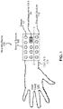
- FIG. 1 is an example view of a wearable device 100 including an array of sensors 108, in accordance with an embodiment.
- the wearable device 100 includes a wearable structure 116 that may be a flexible mechanical substrate such as a plastic (e.g., polyethylene or polypropylene), rubber, nylon, synthetic, polymer, etc.
- the wearable structure 116 is configured to be worn around at least a portion of a user's wrist or arm 104.
- the wearable device 100 includes sensors 112 arranged at different locations on the wearable structure 1 16.
- the sensors can be arranged in a pattern along an inner surface of the wearable structure 116 facing the arm 104 such that the sensors are in electrical contact with the arm 104.
- Each sensor 112 measures electrical signals corresponding to movement or state of internal bodily structures within the user's wrist or arm 104.
- the sensors 112 include electrodes mounted on the wearable structure 116 to measure electrical impedance of the user's wrist or arm 104.
- an inertial measurement unit 128 is fixed to the wearable structure 116 and generates inertial signals corresponding to movement of the inertial measurement unit 128, and thus movement of the user's arm 104.
- the wearable structure 116 secures the wearable device 100 to the user's wrist or arm 104.
- some or all of the wearable structure 1 16 may be a rigid material rather than a flexible material.
- the wearable structure 116 may include a rigid body portion that includes the sensors 1 12, and a band portion that secures the body portion to the user's arm 104.
- the wearable device 100 does not include the inertial measurement unit 128.
- the wearable device 100 is placed on a user's arm 104 to detect a hand position of a hand 120 of the user.
- a hand position includes the angle and position of the palm, knuckles, and fingers of the user's hand and includes parameters corresponding to joints of the hand, edges between pairs of the joints, and angles between pairs of the edges, as illustrated and described in detail below with respect to FIG. 2C .
- Each sensor 1 12 on the wearable device 100 may function individually to receive electrical signals through the arm 104. In another example, pairs of sensors operate together, with some sensors transmitting probe signals and some sensors receiving the electrical signals.
- the sensors 112 receive electrical signals from the user's arm 104 representing the position of the user's hand 120.
- the wearable device 100 may be portable, light weight, and low power, and is suitable for use as a game controller, media controller, keyboard controller, robotic device controller, etc.
- the wearable device 100 may include micro-USB, Bluetooth ® , or Wi-Fi connectivity to interface with a computing device, a VR system, or an HMD.
- the wearable device 100 may be used to render a full hand model in a VR system or track human-object interaction in real environments.
- the sensors 112 include electrodes that generate inputs used to determine the hand position of the user's hand 120 by electrical impedance tomography (EIT) .
- EIT is a noninvasive method in which electrical conductivity, permittivity, or impedance of the user's hand 120 may be inferred from surface electrode measurements.
- the wearable device 100 may apply AC signals at a single frequency or use multiple frequencies to better differentiate between tissues within the user's hand 120.
- the AC signals correspond to wide-bandwidth signals comprising a spectrum of frequencies.
- AC signals may be applied to some or all of the sensors 1 12 and resulting voltages may be received by the sensors 112.
- the resulting impedances and their phases are determined from the currents and the voltages measured. Different values of impedance correspond to different states or arrangements of the internal structures (e.g., joints, bones, tendons, etc.,) of the user's wrist or arm, and thus different hand positions. This process may be repeated to generate a set of measurements of voltages and/or currents by the sensors 112.
- the sensors 1 12 can be arranged in different configurations, as illustrated and described below with reference to FIGs. 2A , 2B , 3A, 3B , and 3C .
- each sensor 112 and the inertial measurement unit 128 is mounted on the wearable structure 1 16 which wraps around the user's arm 104 to ensure the array of sensors 108 covers and can receive electrical signals from different areas of the user's arm 104, as illustrated and described below with reference to FIG. 2B .
- the sensors 112 include electrodes designed to make contact with human skin.
- the electrodes may be circular, square, or rectangular, and may range in diameter or linear dimension. In some embodiments, the electrodes may range in size from 1-IOmm.
- the electrodes may be made of a metallic material, such as Ag-AgCI or a stretchable conductive polymer, such as (3,4-ethylenedioxythiophene) (PEDOT) mixed with polyurethane (PU).
- PEDOT (3,4-ethylenedioxythiophene) mixed with polyurethane
- the electrodes may be fabricated using an Ag-plated polyvinylidene fluoride (PVDF) nanofiber web and metallic threads.
- PVDF polyvinylidene fluoride
- a contact area having a conductive agent and padding may be used on the wearable device 100 behind each electrode to improve subject comfort and reduce contact impedances.
- the conductive agent between the electrode and skin may be a "wet” connection using a conductive gel, which may consist of propylene glycol and NaCl, or a "dry” connection, such as a thin layer of conductive polymer (e.g., carbon-doped PDMS).
- a conductive gel which may consist of propylene glycol and NaCl
- a dry connection such as a thin layer of conductive polymer (e.g., carbon-doped PDMS).
- the electrodes may drive AC signals of a few milliamperes at a frequency of 10-100 kHz into the user's arm 104 and then measure the resulting voltage or current to determine impedance values and the phase of the impedance.
- the electrodes may transmit AC signals corresponding to wide-bandwidth signals including a plurality of frequencies that include the MHz domain.
- the inertial measurement unit 128 generates information that indicates motion of the user's arm 104.
- the inertial measurement unit 128 may include a gyroscope, an accelerometer, and/or a magnetometer.
- the inertial measurement unit 128 measures and reports forces, an angular velocity, and/or a magnetic field surrounding the user's hand 120 or arm 104.
- the inertial measurement unit 128 detects linear acceleration using one or more accelerometers and rotational rate using one or more gyroscopes.
- An example configuration of the inertial measurement unit 128 may contain one accelerometer, gyrometer, and magnetometer per axis for each of the three axes: pitch, roll and yaw.
- the wearable device 100 may detect that the user's arm 104 is moving and, combined with the electrical signals from the sensors 112, improves the identification of the user hand position and facilitates gesture identification.
- the generated inertial signals may be a current, voltage, or digital data.
- FIG. 2A is an example cross sectional view 200 of the wearable device 100 taken along the XY line shown in FIG. 1 , in accordance with an embodiment.
- the cross sectional view 200 shows the user's arm 104 and a tendon 204 within the user's arm 104.
- the wearable device 100 is worn on the user's wrist or arm 104 with the sensors 112 transmitting a probe signal 212 via a conductive agent 120 through the arm 104.
- the conductive agent 120 reduces the impedance presented to the probe signals 212 at the contact between the sensors 112 and the skin of the arm 104.
- the array 108 of sensors 112 does not fully wrap around the wrist or arm 104, and may be arranged only on the palm side of the wrist or arm 104 as shown in FIG. 2 A .
- the probe signal 212 may pass through internal structures of the arm 104, such as the tendon 204, and detected by the sensor 112 shown (or another sensor 112) as the electrical signal 216.
- Sensor 112 may include an electrode that transmits AC signals or DC signals into the wrist or arm 104 of the user as the probe signal 212.
- the probe signals 212 are wide-bandwidth AC signals including a range of frequencies.
- the probe signals 212 may be spread in the frequency domain, resulting in signals 212 with a wider bandwidth.
- the use of wide-bandwidth signals decreases the effects from signal interference.
- the probe signals 212 may be DC signals produced by a power supply such as a battery and having a fixed magnitude (amplitude).
- the probe signals 212 may have a time-varying waveform such as a sinusoidal waveform or AC waveform.
- the probe signal 212 may continuously change polarity every half cycle alternating between a positive maximum value and a negative maximum value respectively with regards to time.
- the time period of the probe signal 212 is the length of time in seconds that the waveform takes to repeat itself from start to finish.
- the amplitude is the magnitude or intensity of the signal waveform measured in volts or amps.
- the phase of each probe signal 212 is measured relative to a common reference such as ground or the probe signal of another sensor. Due to the phase difference, the electrical signal 216 on any sensor reaches a peak value at a different time after one of the other sensors.
- each sensor 1 12 further transmits the probe signals 212 into the user's wrist or arm 104 by varying one or more of a time period of the probe signal 212, an amplitude of the probe signal 212, and a phase of the probe signal 212.
- the sensors 112 transmit probe signals 212 into the user's wrist or arm 104 in a staggered manner, where a different subset of the sensors transmit probe signals 112 at different times.
- the probe signals 212 from two or more sensors 112 can transmit alternating currents of typically a few milliamperes at a frequency of 10-100 kHz. The remaining sensors may be used to measure the resulting voltage signal 216. This procedure may then be repeated for multiple stimulation patterns defining an order of pairs of sensors selected to emit the probe signals 212.
- a single current source is switched between multiple sensors 112 using a multiplexer to generate the probe signals 212.
- a system of voltage-to-current converters one for each sensor 112, each controlled by a digital to analog converter, is used to generate the probe signals 212
- Each electrical signal 216 may include, if the probe signal 212 is an AC signal, properties such as a voltage and a phase of the voltage, or an electric current and a phase of the electric current. If a DC signal is used for the probe signal 212, the electrical signal 216 includes a magnitude of a DC signal.
- the electrical signal 216 measurements may be taken either by a single voltage measurement circuit multiplexed over the sensors 1 12 or a separate circuit for each sensor 112.
- an analog demodulation circuit may be used to convert the alternating voltage to a DC level before further processing by an analog to digital converter.
- the alternating signal may be converted directly before performing digital demodulation.
- the device 100 may operate at multiple frequencies and measure both magnitude and phase of the voltage of the electrical signal 216.
- the impedances derived from the electrical signal 216 may be passed on to a computing device (e.g., a separate host system or a processor integrated with the wearable device 100) to perform image reconstruction and display based at least in part on the electrical signal 216.
- a computing device e.g., a separate host system or a processor integrated with the wearable device 100
- phase data of the electrical impedance between each pair of sensors 1 12 is extracted from the measured electrical signal 216 between the pair of sensors.
- the impedance data stream transmitted from the sensors to a position computation circuit includes sets of pairwise impedance measurements from each pair of sensors. Each combination of sensors is used to perform pairwise measurements that, if the number of sensors is denoted by N, result in N2 impedance values.
- the information extracted from the measured electrical signals 216 includes a change in impedance over time for each pair of sensors (impedance/s). This impedance/s is indicative of changes in the state of the user's arm 104 over time, and thus is used to determine the user hand position.
- the sensors 1 12 are arranged on the wearable structure 1 16 across the user's wrist or arm 104 to detect the state of the soft tissue, such as the tendon 204.
- the wearable device 100 may measure any or all of muscle contractions, tendon 204 motion, tendon 204 length, and joint stiffness in order to determine the hand position of the user's hand 120. For example, combinations of such values measured from the user's arm 104 can indicate the angle formed by bones between joints within the user's hand 120.
- the position of the hand can be represented by a collection of values representing the angles formed between joints in the hand as derived from the electrical signal 216.
- the wearable device 100 operates by determining the state of structures within the arm 104 that is connected to the hand 120 by the wrist. For example, the state of bones such as the radius and ulna, the radial styloid and the ulnar styloid, the carpal bones, the metacarpals, etc., may be determined to identify the position of the user's hand 120. The state of joints such as the carpometacarpophalangeal joint, the metacarpophalangeal joint, and the interphalangeal joint, etc., may be determined from the electrical signals 216 to identify the position of the user's hand 120.
- the state of muscles such as intrinsic muscles, tendons such as the flexor tendons, extensor tendons, tendon sheaths, and median nerve and ulnar nerve may be determined from the electrical signals 216 to identify the position of the user's hand 120.
- the wearable device 100 can determine user hand pressure when holding objects and can distinguish between a user who is grasping an object in the hand 120 and a user who is making a grasping gesture with an empty hand 120.
- FIG. 2B is an example cross sectional view of a wearable device 250 having sensors 112 surrounding the user's arm 104, in accordance with an embodiment.
- the wearable structure 1 16 wraps around the wrist or arm 104 of the user.
- the sensors on one side of the arm 104 may transmit probe signals 212 into the user's arm and sensors on another side of the arm 104 may receive electrical signals 256 traveling through the tendon 204 of the user's arm 104. In this manner, the system is able to measure cross-sectional impedance properties of the wrist or arm 104.
- FIG. 2C is an example illustration of a hand shape model 280 of a user, in accordance with an embodiment.
- the hand position of the user is represented with reference to the hand shape model 280.
- the hand shape model 280 includes parameters that correspond to joints of the hand 120 of the wrist or arm 104 of the user, edges between pairs of the j oints, range of angles between pairs of the edges, and a mesh including vertices and for each vertex, a relationship (e.g., distance) between the vertex and one or more joints.
- the electrical signals generated by the wearable device 100 are used to determine the hand position with reference to the hand shape model 280, such as the angles defined between pairs of edges between joints.
- the hand shape model 280 defines a deformable shape and size of the hand 120.
- hand shape model 280 includes a skeleton 282 and a mesh 284.
- the skeleton 282 includes hand features 286, representing nodes (joints) of the skeleton. At least some hand features 286 have fixed distances between other hand features 286, which is shown by the hand edges 288 of the skeleton 282.
- the hand edges 288 are models for bones of the hand 120, and the hand features 286 are models for joints that connect the bones.
- Each hand feature 286 is associated with one or more degrees of freedom (DOF) defining the range of motion of the joint.
- the hand feature at the wrist includes two degrees of freedom (e.g., pitch and yaw).
- the hand features 286 at each knuckle include two degrees of freedom (e.g., roll and yaw).
- the hand features 286 at each finger joint include one degree of freedom (e.g., yaw).
- Degrees of freedom may include rotational or translational degrees of freedom.
- Each degree of freedom may be associated with a range of values, such as may be defined by a maximum value and a minimum value, representing how much a joint can move along the degree of freedom.
- a hand position is defined by a particular state of the hand shape model 280.
- a set of values for each degree of freedom of the hand features 286 may define a particular hand pose.
- the mesh 284 of the hand shape model 280 defines the surface of the user hand model 280.
- the mesh 284 may include vertices, where each vertex is attached with a part of the skeleton 282, such as a hand feature 286 or location along a hand edge 288.
- the vertices when interconnected form a polygon mesh defining a model of the hand surface. For example, a vertex may have a predefined distance from an attached hand feature 286. If a hand feature 286 is moved, the attached vertices move accordingly such that the mesh 284 changes with movement of the skeleton 282.
- vertices of the mesh 284 may be attached to more than one location of the skeleton 282.
- FIG. 3A is an example view of an array 108 of sensors 1 12, in accordance with an embodiment.
- Each sensor 1 12 is mounted on the wearable structure 1 16, as illustrated and described above with reference to FIGs. 2A or 2B .
- the sensors 1 12 may be arranged in a rectangular grid, here having 3 rows and 5 columns.
- the array 108 may be mounted on the wearable structure 1 16 with the inertial measurement unit 128. In some embodiments, inertial measurement unit 128 is omitted from the wearable structure 116.
- FIG. 3B is an example view of a checkerboard partem array 300 of sensors 112, in accordance with an embodiment.
- Each sensor 112 is mounted on the wearable structure 1 16, as illustrated and described above with reference to FIGs. 2A or 2B .
- the sensors 1 12 are arranged in an altemating checkerboard pattern 300.
- the checkerboard pattern array 300 can be mounted on the wearable structure 116 with the inertial measurement unit 128. In some embodiments, inertial measurement unit 128 is omitted from the wearable structure 1 16.
- FIG. 3C is an example view of a non-uniform distribution array 360 of sensors 112, in accordance with an embodiment.
- Each sensor 1 12 is mounted on the wearable structure 116, as illustrated and described above with reference to FIGs. 2A or 2B .
- the arrangement of sensors 112 on the wearable structure 1 16 does not follow a regular pitch value, and the sensors 1 12 are instead arranged to optimize detection of important structures in the arm 140.
- a greater concentration of sensors 112 is located in a cluster 368 on the wearable structure 116 that covers locations of higher interest internal to the user's arm 104 (e.g., for extracting angles between joints and hand position), such as the carpal tunnel zone.
- a smaller concentration of sensors 112 is located in areas of lower interest 364.
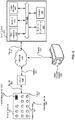
- FIG. 4 is an example block diagram of a system for tracking a user's hand position, in accordance with an embodiment.
- the system includes the wearable device 100, a host system 428, and a head-mounted display (HMD) 424.
- the wearable device includes the array of sensors 108 and a circuit 400 coupled to the array of sensors 108.
- the system illustrated in FIG. 4 may represent a virtual reality (VR) system, an augmented reality (AR) system, or a mixed reality (MR) system.
- VR virtual reality
- AR augmented reality
- MR mixed reality
- the array of sensors 108 may transmit the probe signals 212 to the user's arm 104 and receive the electrical signals 216 from the user's arm 104 as illustrated and described above with respect to FIGs. 2A and 2B .
- the array of sensors 108 transmits signals 404 to the circuit 400.
- the signals 404 may be the electrical signals 216.
- the circuit 400 transmits signals 408 to the host system 428.
- the signals 408 may be the electrical signals 216, information derived from the electrical signals 216, or a computed output describing the position of the user's hand 120 as calculated by the circuit 400 from the electrical signals 216.
- the information derived from the electrical signals 216 may include aggregate values based on an electrical impedance and a phase of the impedance measured between each pair of sensors 1 12.
- the electrical impedance is determined based on the probe signals 212 transmitted into the wrist or arm 104 of the user by the pair of sensors 1 12 and the electrical signals 216.
- the computed output may be any discrete, discontinuous representation of information describing the hand position of the user's hand 120 or analog signals representing changes in the position of the user's hand 120 using a continuous function.
- the wearable device 100, host system 428, and HMD 424 may communicate via a network 412, which may include any combination of local area and/or wide area networks, using both wired and/or wireless communication systems.
- the host system 428 may include an input interface circuit 432, a memory 436, an output interface circuit 440, a position computation circuit 448, and a camera 452.
- the input interface circuit 432, memory 436, output interface circuit 440, position computation circuit 448, and camera 452 may communicate via a bus 444.
- the input interface circuit 432 receives the electrical signals 216 from the sensors 1 12.
- the input interface circuit 432 receives the inertial signals from the inertial measurement unit 128 and/or receives images from one or more cameras.
- the input interface circuit 432 is an interface circuit made of digital logic and/or analog circuitry to receive the electrical signals 216 from each sensor 112 of the array of sensors 108.
- the input interface circuit 432 may derive information from the electrical signals 216, such as the induction of voltages in the user's wrist or arm 104 self-induced by the magnetic fields of currents (inductance).
- the derived information may represent the electrostatic storage of charge in the internal structures of the user's wrist or arm 104 induced by voltages (capacitance). Deriving the information may include analyzing the electrical signals 216, such as by using phase determination, Hilbert transforms, etc., to determine an aggregate value. If the sensors 1 12 drive a DC signal into the user's wrist or arm 104, the derived information may represent an impedance with zero phase angle.
- the derived information may represent a shape of a wave of the electrical signals 216.
- a sigmoid shape may represent a single frequency while square pulses may represent a spectrum of frequencies.
- Deriving the information may include extracting the shape of the waveform of the received electrical signals 216, e.g., by using the Hough transform to detect the analytically defined shape of the waveform of the received electrical signals 216.
- the derived information may represent a frequency -domain representation of the electrical signals 216. Deriving the information may include creating a frequency-domain representation of the electrical signals 216. Converting the electrical signals 216 from the time or space domain to the frequency domain, e.g., using a Fourier transform, such as fast Fourier transform (FFT) may be used to create a frequency - domain representation of the electrical signals 216.
- Example frequency domain information derived from the electrical signals 216 are a magnitude and a phase component of each frequency, which frequencies are present, which are missing, etc.
- the derived information may represent a time-domain sample of the electrical signals 216. Deriving the information may include performing time-domain sampling of the electrical signals 216. Time-domain sampling reduces the electrical signals 216 to a set of discrete-time samples, such as a set of values at a point in time and/or space.
- the memory 436 may be organized as a database, table, file, etc., stored on one or more of memory cards and computer hard drives.
- the memory 436 stores the user hand shape model 280 for hand tracking, as illustrated and described in detail above with reference to FIG. 2C .
- the user hand shape model 280 defines the shape of the hand in 3-dimensional (3D) space, and is deformable to define the poses or positions of the hand 120.
- the user hand shape model 280 includes "hand features" that represent joints. These "hand features" 286 represent the user's joints themselves and are different from the "features 508" extracted by the position computation circuit 448 from the electrical signals 216.
- the features 508 extracted by the position computation circuit 448 from the electrical signals 216 are a set of values representing angles defined between hand features 286.
- the hand features 286 may include degrees of freedom representing joint orientations. Accordingly, the hand position of a user, or changes in hand position, can be defined by a set of values representing joint orientations for each of the joints of a user hand shape model.
- a description of the user hand shape model 280 is in U. S. Application No. 15/487,355, filed April 13, 2017 .
- the user hand shape model 280 customized for a user, may be generated as a set of principle component hand shape models, such as a weighted combination of ten principle component hand shape models. Each principle component hand shape model may control a linearly uncorrelated parameter of user hand shape. The use of a limited number of principle component hand shape models reduces determination of user hand shape to a smaller number of variables, and is described in U.S. Application No. 15/487,361 , filed April 13, 2017 .
- the position computation circuit 448 is coupled to the input interface circuit 432.
- the position computation circuit 448 computes, using features extracted from the electrical signals 216 as input to a machine learning model, an output that describes the position of the user's hand 120 and/or changes in hand position of the user's hand 120.
- the machine learning model may define relationships between the electrical signals 216 as input and parameters of a hand shape model 280 as output.
- the position computation circuit 448 may be part of a central processing unit (CPU) that carries out the instructions of a computer program by performing the basic arithmetic, logical, control and input/output (I/O) operations specified by the instructions.
- CPU central processing unit
- one or more components of the host system 428 shown in FIG. 4 are located in the HMD 424 or the wearable device 100.
- the computation circuit 448 may be located in the circuit 400, which may be part of the wearable device 100 or the HMD 424.
- the output interface circuit 440 is coupled to the position computation circuit 448 and transmits the computed output that describes the hand position of the user's hand 120. For example, if the output interface circuit 440 is included in the circuit 400, it will communicate the computed output to the host system 428 or the HMD 424. If the output interface circuit 440 is included in the host system 428, it will communicate the computed output to the HMD 424.
- the position computation circuit 448 includes a machine learning model training and/or inferencing.
- the machine learning model can be trained using training data sets of example features extracted from electrical signals, and corresponding expected outputs (e.g., a set of values defining the hand position).
- at least a portion of the training data is generated in a training process where the user provides hand motions and gestures and that are captured using optical markers, as described in detail below with reference to FIG. 5 .
- the computed output may further describe forces exerted by a hand 120 of the user on objects touching the hand 120 of the user.
- the forces may be represented by the clenched state of muscles, tendons, and other intemal structures in the user's wrist or arm 104 that are described by the computed output based on the electrical signals 216.
- the sensors may measure the passive electrical properties of the clenched biological tissues exerting the forces on the obj ects based on the differences in resistivity between the tissue types and the different impedance spectra of skeletal muscle and other tissue.
- the camera 452 may be a depth camera, a Red-Green-Blue (RGB) camera, an Infrared camera, or a camera mounted on the HMD 424.
- the camera 452 may capture images of the user's hand 120 by resolving distances based on the known speed of light or measuring the time-of-fiight of a light signal between the camera and the user's hand 120 for each point of the image.
- the camera 452 may use independent charge coupled device (CCD) sensors to acquire the three RGB color signals for color image acquisitions of the user's hand 120.
- the camera 452 may be a thermographic camera (also called an Infrared camera or thermal imaging camera) that forms an image using infrared radiation using wavelengths as long as 14,000 nm (14 ⁇ m).
- the camera 452 may capture ground truth hand positions for training data, as described below with reference to FIG. 5 . Although the camera 452 may be used for training, it is not needed for inferencing changes in hand positions.
- the HMD 424 is connected to the wearable device 100 and host system 428 via the network 412.
- the HMD 424 may include a display device, worn on a user's head or as part of a helmet that has an electronic display panel in front of the user's eyes to display computer-generated imagery (CGI) and/or live imagery from the physical world.
- CGI computer-generated imagery
- the computed output that describes the hand position of the user's hand 120 generated from the electrical signals 216 of the array of sensors 108 may be translated into an action in a virtual scene presented to the user by the display panel.
- the HMD 424 receives signals 420 from the network 412 that may be the electrical signals 216 or the computed output corresponding to the hand position of the user's hand 120 after the circuit 400 or host system 428 has processed the electrical signals 216 to determine the position of the user's hand 120.
- the HMD 424 receives a video feed including a virtual scene that is generated based at least in part on changes to the position of the user's hand.
- the input interface circuit 432 may receive image signals from the camera 452 or a camera mounted on the HMD 424.
- the position computation circuit 448 may determine comparison signals by comparing the image signals with the computed output. For example, the position computation circuit 448 may use image differencing to determine changes between the image signals and the computed output for the values of joint orientations of the user hand shape model 280.
- the position computation circuit 448 may further determine an error or loss function for the difference between the hand position as derived from the image and hand position as derived from the machine learning model. In a backward pass, the parameters of the machine learning model are updated to minimize the loss or error function.
- a gradient is computed with respect to the parameters of the machine learning model, and the parameters are optimized toward a negative gradient direction.
- the error between the image signals and the computed output may be transformed into an image based on the result.
- the Hutchinson metric may be used to measure a discrepancy between the image signals and the computed output.
- the output interface circuit 440 may further transmit the comparison signals to the host system 428 or HMD 424.
- Other types of machine learning may be used.
- the machine learning model uses linear regression rather than gradient-based optimization.
- computing the output that describes the hand position of the user's hand 120 from the electrical signals 216 may be performed by the circuit 400, the host system 428, or circuits within the HMD 424 in different embodiments.
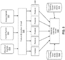
- FIG. 5 is an example block diagram describing components associated with training a machine learning model 556, in accordance with an embodiment.
- the process may have different and/or additional steps than those described in conjunction with FIG. 5 .
- Some steps may be executed in parallel.
- some of the steps may be executed in parallel and some steps executed sequentially.
- some steps may execute in a pipelined fashion such that execution of a step is started before the execution of a previous step.
- the block diagram illustrates a feature extraction circuit 548 and the machine learning model 556 within the position computation circuit 448.
- Information derived from the electrical signals 216, as described above with reference to FIG. 4 is received by the feature extraction circuit 548.
- the information may include impedance values and phase data of the electrical impedance measured between each pair of sensors 112.
- the information may represent the electrical opposition that the internal structures 204 of the user's arm 104 present to the probe signals 212.
- the information may be a complex ratio of the electrical voltage signals 216 received to the probe current signals 212 transmitted, and may possess both magnitude and phase. If the number of sensors is denoted by N, this results in N2 such impedance values.
- the information includes a change in impedance over time for each pair of sensors (impedance/s). This impedance/s is indicative of changes in angles between joints in the user's hand 120 over time.
- the feature extraction circuit 548 extracts features 508 from the electrical signals 216 or from the information derived from the electrical signals 216.
- the features 508 include angles between joints defining the hand position of a hand 120 of the wrist or arm of the user.
- the features 508 extracted are a set of values representing angles defined between hand features 286.
- the angles between joints can be defined with respect to a user hand shape model 280, and can be used to render a full high-fidelity hand that corresponds to the hand shape model 280 and hand position of the user.
- the features 508 include a reduced representation of a change in the hand position of a hand 120 of the wrist or arm 104 of the user.
- the features 508 extracted by the feature extraction circuit 548 are encoded using the reduced representation.
- the reduced representation defines a difference between a present hand position of the hand 120 of the wrist or arm 104 of the user and a previous hand position of the hand 120 of the wrist or arm 104 of the user.
- Temporal redundancy between neighboring image frames may be used to enable compression in the reduced representation.
- the data transmitted by the sensors 1 12 may correspond to N2 ⁇ 8 image frames for time sampling, where the number of sensors 112 is N, and N2 is the number of sensor pairs measuring electrical impedance of the user's arm 104.
- the data transmitted by the sensors 112 would include only motion vectors that describe the transformation from one image frame to another.
- the reduced representation 508 for the 8 image frames would therefore not include values for joints in each frame, but only the joint values that change between consecutive frames.
- the processing and storage requirements for information related to hand position are reduced because only changes between frames are represented in data.
- the machine learning model 556 may be trained using compressed training data and can output compressed training data.
- the inertial measurement unit 128 generates inertial signals 504 corresponding to movement of the wearable device 100, as illustrated and described above with reference to FIG. 1 .
- the position computation circuit 448 computes, using features derived from the inertial signals 504 in addition to the features from the signals 216 with the machine learning model 556, the output that describes the hand position of the hand 120 of the wrist or arm of the user.
- the camera 452 generates image signals 520 of joints and angles between fingers of the hand 120 of the wrist or arm 104 of the user.
- the position computation circuit 448 computes, using information derived from the image signals 520 in addition to the features from the signals 216 with the machine learning model 556, the output that describes the hand position of the hand 120 of the wrist or arm 104 of the user.
- the image signals 520 from the camera provide an expanded data set for extracting hand position features 508, and can increase the accuracy of the extraction.
- ground truth expected outputs describing forces exerted by the hand of the user on objects touching the hand of the user may be determined using an array of force sensors.
- the force data corresponds to the ground truth.
- the machine learning model 556 is trained to learn a continuous correlation between training inputs and hand exertion. In training, a user may grasp the force sensor array at a variety of different levels of grip force (i.e., hand exertion), and electrical data from the wearable device 100 is collected.
- the electrical signals 216 may change as the muscles, tendons, and other internal structures change under different levels of hand exertion.
- the force sensor data (“ground truth") is correlated to the electric signal data 216 using machine learning techniques, and a continuous model is created to estimate hand exertion from the electrical data 216.
- ground truth expected outputs describing forces exerted by the hand of the user may be determined without using force sensors.
- subjective levels of hand exertion (“ground truth”) may be correlated directly to the electrical signals 216.
- a user may grasp objects with a "light,” “medium,” or “high,” etc., grip force (i.e., hand exertion).
- the electrical signals 216 are then measured from the wearable device 100.
- the electrical signals 216 may change as the muscles, tendons, etc., change under different levels of hand exertion.
- the user-labeled hand exertions are correlated to the electric signal data 216.
- Machine learning techniques are used to create a model to estimate the hand exertion from the electrical data 216.
- the feature extraction circuit 548 extracts features 508 to facilitate adjusting the parameters of the machine learning model 556.
- the extracted features 508 are used as inputs to the machine learning model 556, whose output can be compared with ground truth outputs stored in the training output data store 516.
- the electrical signals 216 or their extracted information is retrieved from the training input data store 512 and input to the feature extraction circuit 548 to generate the features 508.
- the training input data store 512 may be organized as a database, table, file, etc., stored on one or more of removable or non-removable memory cards, computer hard drives, etc.
- the training input data store 512 includes multiple data fields, each describing one or more attributes of the training input data.
- the training input data store 512 may contain electrical signals 216, inertial signals 504, image signals 520, or their extracted values, which are used as inputs to the feature extraction circuit 548.
- the training output data store 516 stores expected hand positions of the user's hand 120 that correspond with the inputs stored in the training data input store.
- the training input data store 512 and training output data store 516 store information captured from multiple users.
- the machine learning model 556 is trained using training sets including information from the training input data store 512 and the training output data store 516.
- the training output data store 516 may be organized as a database, table, file, etc., stored on one or more of removable or non-removable memory cards, computer hard drives, etc.
- the training output data store 516 may store associations between known features 508 and known hand positions corresponding to the features 508.
- the training output data store 516 may store expected outputs, i.e., hand positions extracted from information from the inertial signals 504 or camera frames.
- the user's hand 120 whose position is to be tracked for training the machine learning model 556 is equipped with optical markers.
- Optical markers may be light reflectors (passive markers, e.g., retroreflectors) or light emitters (active markers, e.g., LEDs).
- a tracking camera may be used to scan and detect the light that comes from the optical markers.
- the images captured are processed to identify and calculate potential marker positions (in 2D image coordinates). This 2D data may be combined to calculate 3D positions of the optical markers.
- the results of such measurements (coordinates that describe the positions of the optical markers, and hence the position and orientation of the user's hand 120 carrying the markers) is stored in the training output data store 516 and used to train the machine learning model 556.
- the camera 452 generates image signals 520 corresponding to movement of the user's hand 120.
- a separate neural network may be trained to generate expected outputs derived from the image signals 520 that describe the hand position of the hand 120 of the wrist or arm 104 of the user. This process is described in U.S. Application No. 15/487,355, filed April 13, 2017 , and U.S. Application No. 15/487,361, filed April 13, 2017 .
- These expected outputs may be stored in the training output data store 516.
- the position computation circuit 448 may receive image signals 520 from the camera 452, as illustrated and described above with reference to FIG. 4 , for training of the machine learning model 556.
- the expected output corresponds to 8 camera frames representing captured changes in position of the hand 120 of the wrist or arm 104 of the user.
- the position computation circuit 448 may also create training data sets for the training output data store 516 by receiving image signals 520 from a camera mounted on an HMD.
- the inertial measurement unit 128 generates inertial signals 504 corresponding to movement of the wearable device 100.
- the machine learning model 556 is trained to generate expected outputs derived from the inertial signals 504 that describe the hand position of the hand 120 of the wrist or arm 104 of the user. These expected outputs may be stored in the training output data store 516.
- the objective of training the machine learning model 556 is to enable it to perform accurately on new, unseen inputs after having experienced the inputs and expected results of the training data sets.
- Several different approaches to training may be used, including decision tree learning, association rule learning, neural networks, deep learning, inductive logic programming, support vector machines, clustering, Bayesian networks, reinforcement learning, and representation learning, etc.
- a gradient-based optimization approach an error in a cost function (in a forward pass) and the gradient with respect to the parameters of the model may be computed; then the parameters may be moved towards the negative gradient direction (in a backward pass).
- a neural network there may be multiple layers of cost functions; the training is performed for each layer.
- linear regression closed form solutions are computed and the output may be directly written out.
- the training of the machine learning model 556 may be accomplished in two passes. First, in a forward pass, training features 508 are extracted from impedances derived from the electrical signals 216 and the inertial signals 504. In this manner, information derived from the electrical signals 216 is input into the feature extraction circuit 548. The output of the feature extraction circuit 548 is the set of features 508. The features 508 correspond to angles between joints defining hand positions. In some embodiments, the features correspond to a reduced representation of a change in hand position of the hand 120 of the wrist or arm 104 of the user. Each feature 508 is therefore an output extracted from a set of inputs 216 and 504.
- the position computation circuit 448 may determine an error or loss function between each feature 508 and the expected outputs (e.g., from camera 452) stored in the training data output store 516. Second, in a backward pass, the parameters of the machine learning model 556 are adjusted to minimize the error or loss function. In the next forward pass, this updated machine learning model 556 is used. In this manner, large volumes of training sets may be collected across multiple users.
- the machine learning model 556 may be a recurrent neural network (RNN) model, which is a class of artificial neural network where connections between units form a directed cycle. This creates an internal state of the machine learning model 556 which allows it to exhibit dynamic temporal behavior.
- RNN recurrent neural network
- the position computation circuit 448 can use its internal memory to process arbitrary sequences of inputs, such as features extracted from the electrical signals 216.
- dimensionality reduction may be used to reduce the dimensions of a full hand shape model to reduce the amount of data in the features 508 and reduce the complexity of the machine learning problem.
- PCA may applies dimensionality reduction (e.g., via linear discriminant analysis (LDA), principle component analysis (PCA), or the like) to reduce the amount of data in the feature vector 410 to a smaller, more representative set of data.
- LDA linear discriminant analysis
- PCA principle component analysis
- PCA is a statistical procedure that uses an orthogonal transformation to convert a set of observations of possibly correlated variables into a set of values of linearly uncorrelated variables called principal components. The number of principal components is less than or equal to the smaller of the number of original variables or the number of observations.
- expected outputs corresponding to the full hand shape model may be measured by the camera 452 as image signals 520. These expected outputs may be reduced to a smaller model (e.g., 10 features) using PCA and stored in the training output data store 516.
- the machine learning model 556 may be trained using training sets of electrical signals 216, inertial signals 504, image signals 520, or their extracted values corresponding to the reduced model (10 features) stored in the training input data store 512.
- the input data is used by the trained model to predict an output corresponding to the reduced hand shape model (10 features).
- the output corresponding to the reduced hand shape model (10 features) may then be projected back to the full hand shape model (22 joint angles) for use.
- the position computation circuit 448 receives inputs 216 and/or 504 from the sensors 112 and the inertial measurement unit 128 (e.g., in a live environment) and uses the extracted features 508 with the trained machine learning model 556 to compute the output.
- the benefits and advantages of this method are that a small set of input data (electrical signals 216) is generated for the user. No camera or image processing is needed, although in embodiments, image signals may be used either as inputs to the model 556, in training the model 556, or for calibration of the system to determine errors between the output computed by the model 556 and live image signals.
- FIG. 6 is a flowchart illustrating a process 650 for training the machine learning model 556 to track the user's hand position based on training electrical signals, and a process 654 for inferring the user's hand position based on electrical signals 216, in accordance with an embodiment.
- the processes may have different and/or additional steps than those described in conjunction with FIG. 6 . Steps of the processes may be performed in different orders than the order described in conjunction with FIG. 6 . Some steps may be executed in parallel. Alternatively, some of the steps may be executed in parallel and some steps executed sequentially. Alternatively, some steps may execute in a pipelined fashion such that execution of a step is started before the execution of a previous step.
- the circuit 400 or host system 428 receives 600 the electrical signals 216 from the sensors 1 12 arranged at different locations on the wearable structure 116 worn around at least a portion of a wrist or arm 104 of the user. Each sensor 1 12 measures the electrical signals 216 corresponding to movement of structures within the wrist or arm 104 of the user.
- the feature extraction circuit 548 extracts 608 training features 508 from the electrical signals 216.
- the impedance and phase of the electrical impedance measured between each pair of sensors 112 is derived.
- the information derived from the measured electrical signals 216 includes a change in impedance over time for each pair of sensors (impedance/s).
- the features 508 extracted from the electrical signals 216 or from the information derived from the electrical signals 216 may include angles between joints defining positions of a hand 120 of the wrist or arm 104 of the user, and a reduced representation of a change in hand position of a hand 120 of the wrist or arm 104 of the user.
- the process 650 is a training process used to generate the machine learning model 556, such as by deriving parameters for neural network layers that implement the machine learning model 556.
- the machine learning model 556 is trained 612 using the extracted features 508, information corresponding to known hand positions from the training input data store 512, and expected outputs from the training output data store 516 to determine the hand position of a hand 120 of the user based on the features 508.
- the position computation circuit 448 may receive image signals 520 from the camera 452, as illustrated and described above with reference to FIGs. 4 and 5 .
- the expected output may correspond to 8 camera frames representing captured positions of the hand 120 of the wrist or arm 104 of the user.
- the inferencing process 654 can be performed for real-time user hand tracking for a user.
- the sensors 1 12 in the wearable device 100 transmit 616 probe signals 212 to the internal structures 204 of the user's arm 104, as illustrated and described above with respect to FIG. 2A .
- the input interface circuit 432 receives 620 electrical signals 216 from the sensors 1 12.
- the electrical signals 216 correspond to movement of structures within the wrist or arm 104 of the user.
- the feature extraction circuit 548 extracts 628 features 508 from information such as impedance values derived from the electrical signals 216.
- the position computation component 448 transmits the features 508 for inferencing to the machine learning model 556 to generate 632 an output that describes a hand position of the user's hand 120.
- the machine learning model 556 having been trained using similar feature sets, is applied to the features 508 extracted during the inferencing.
- classifications, binaries, or other scores, based on the new features are determined using the machine learning model 556.
- a score associated with each user hand position in the training output data store 516 is determined. The score associated with each user hand position may indicate a likelihood that the electrical signals 216 correspond to that user hand position.
- a score associated with each user hand position is determined by evaluating an expression representing a weighted aggregate of scores associated with features 508.
- the weight associated with a feature may be predetermined, for example, configured by an expert user. Features that are most determinative of certain hand positions for a particular user may be weighted more.
- the output interface circuit 440 transmits 636 the computed output to the host system 428 or the HMD 424.
Description
- The present disclosure generally relates to tracking of body motions using sensors, and specifically to tracking of human hand positions using electrical impedance measurement.
- Bodily motion such as gestures can be an appealing way for a user to interact with computing devices, since gestures are already a natural part of how people communicate. A hand gesture tracking device may enable a user to control or interact with computing devices without physically touching them. For example, a gesture tracking device may be used by a user to control memory or display devices in a local or remote environment.
- Gesture recognition systems can be unwieldy, constraining, and uncomfortable to use. For example, glove-like devices that use mechanical signals to track hand motion may disturb the haptic sense of the hand. They may also be difficult to customize to different users having varying hand size. Camera-based gesture tracking systems detect the user's hand area from captured images, but often require the user's entire hand to be in the camera view range. They may also suffer failure when there is object occlusion in an image. Patent publications
US 2004/068409 A1 ,US 2012/188158 A1 ,US 2016/091980 A1 ,US 2015/091790 A1 ,US 2017/139484 A1 ,US 2009/327171 A1 ,US6244873 ,US 2013/317648 A1 ,US 2016/282947 A1 ,US 2012/209134 A1 discuss information that is useful for understanding the background of the invention. - Gesture trackers are thus awkward to use, difficult to manage, and subject to distortion from the system arrangement or surrounding environment. The cost of traditional gesture trackers may also be high, thus limiting user adoption rate. Furthermore, gesture recognition systems are limited to a small set of predefined gestures. For these and other reasons, such gesture recognition systems are unsuitable for effective hand tracking for head-mounted displays (HMDs).
- Accordingly, the present invention discloses methods, systems and head-mounted displays according to the appended claims. Embodiments relate to a wearable device for tracking human hand motion using electrical impedance measurement of the user's arm. Sensors located on the wearable device receive electrical signals from the user's wrist or arm corresponding to a hand position of the user. Information is extracted from the electrical signals (e.g., impedance values indicating the state of the user's arm structures such as tendons, and thus also indicating the hand position or pose of the user), wherein the sensors include electrodes that generate inputs used to determine the hand position of the user's hand by electrical impedance tomography. The impedance or other extracted values from the electrical signals may be used as input to a position computation circuit implementing a machine learning model. The position computation circuit determines the hand position of the user from the inputs using the machine learning model. In some embodiments, the wearable device includes an inertial measurement unit (IMU) that measures motion of the user's arm, and provides inertial signals to the position computation circuit as an input for determination of the hand position. In some embodiments, the machine learning model is trained using ground truth hand positions extracted from video images of the user's hand taken concurrently with the capture of the electronic signals.
- In one embodiment, a system includes a wearable device including sensors arranged on the wearable device. Each sensor measures electrical signals transmitted from a wrist or arm of a user. A position computation circuit is coupled to the sensors. The position computation circuit computes, using information derived from the electrical signals with a machine learning model, an output that describes a hand position of a hand of the wrist or arm of the user.
- In one embodiment, the position computation circuit is located in the wearable device.
- In one embodiment, the position computation circuit is located in a host system or other computing device external to the wearable device.
- In one embodiment, each sensor includes an electrode and a conductive agent located between the electrode and the wrist or arm of the user. Each sensor can transmit an alternative current (AC) signal, a direct current (DC) signal, or a wide-bandwidth AC signal including multiple frequencies, preferably into the wrist or arm of the user.
- In one embodiment, each electrical signal may comprises one of: a voltage and a phase of the voltage; an electric current and a phase of the electric current; or a magnitude of a DC signal.
- In one embodiment, the sensors are arranged in a grid array or a checkerboard pattern.
- In one embodiment, the information derived from the electrical signals includes aggregate values based on an electrical impedance measured between each pair of sensors. The electrical impedance is determined based on probe signals transmitted into the user's wrist or arm by the pair of sensors and the measured electrical signals. In one embodiment, the derived information may include a shape of a wave of the electrical signals, a frequency-domain representation of the electrical signals, or a time-domain sample of the electrical signals.
- In one embodiment, the position computation circuit extracts features from the information derived from the electrical signals. The features include one or more of angles between joints defining the hand position of a hand of the wrist or arm of the user, and a reduced representation of a change in the hand position of a hand of the wrist or arm of the user. The reduced representation defines a difference between a present hand position of the hand of the wrist or arm of the user from a previous hand position of the hand of the wrist or arm of the user.
- In one embodiment, each sensor further transmits a probe signal into the user's wrist or arm by varying a time period of the probe signal, an amplitude of the probe signal, or a phase of the probe signal.
- In one embodiment, a first sensor transmits a probe signal into the user's wrist or arm by staggering the transmission of the probe signal with respect to transmission of other probe signals by other sensors.
- In one embodiment, an inertial measurement unit generates inertial signals corresponding to movement of the wearable device, and the user's arm. The position computation circuit further computes, using information derived from the inertial signals with the machine learning model, the output that describes the hand position of the hand of the wrist or arm of the user.
- In one embodiment, the inertial measurement unit includes one or more of a gyroscope, an accelerometer, and a magnetometer.
- In one embodiment, one or more cameras generate image signals of the user's hand, such as images that show the hand position from one or multiple angles. The position computation circuit further computes, using information derived from the image signals with the machine learning model, the output that describes the hand position of the hand of the wrist or arm of the user.
- In one embodiment, the camera is a depth camera, a Red-Green-Blue (RGB) camera, an Infrared camera, or a camera mounted on an HMD.
- In one embodiment, an inertial measurement unit generates inertial signals corresponding to movement of the wearable device. The position computation circuit further trains the machine learning model to generate, using information derived from the inertial signals, the output that describes the hand position of the hand of the wrist or arm of the user.
- In one embodiment, a camera generates image signals of the hand of the wrist or arm of the user. The position computation circuit further trains the machine learning model to generate, using information derived from the image signals with the machine learning model, the output that describes the hand position of the hand of the wrist or arm of the user.
- In one embodiment, the computed output further describes forces exerted by the hand of the user on objects touching the hand of the user. The structures of the user's arm, such as the tendons, are in different states when the hand is exerting force compared with when the hand is relaxed even if the overall position of the hand looks similar. The use of electrical signals for hand tracking thus allows for even more types of data extraction than possible with other types of sensor tracking systems.
- In one embodiment, the position computation circuit further receives image signals from a camera mounted on an HMD. Comparison signals are determined by comparing the image signals with the computed output. The comparison signals are transmitted to a host system.
- In one embodiment, the computed output includes parameters of a hand shape model. The parameters correspond to joints of the hand of the wrist or arm of the user, edges between pairs of the joints, angles between pairs of the edges, and a mesh including vertices and for each vertex, a distance between the vertex and one or more joints.
- In one embodiment, an HMD (head-mounted display) may comprise:
- a position computation circuit coupled to a plurality of sensors arranged at different locations on a wearable device, each sensor configured to measure electrical signals transmitted from a wrist or arm of a user, the position computation circuit configured to compute, using information derived from the electrical signals with a machine learning model, an output that describes a hand position of a hand of the wrist or arm of the user; and
- a display panel configured to receive the computed output from the position computation circuit.
- In one embodiment, an HMD may comprise:
a camera configured to generate image signals of the hand of the wrist or arm of the user, wherein the position computation circuit is further configured to compute, using information derived from the image signals with the machine learning model, the output that describes the hand position of the hand of the wrist or arm of the user. - The camera may be a depth camera, a Red-Green-Blue (RGB) camera, an Infrared camera, or a camera mounted on the HMD.
- In one embodiment, an HMD may comprise:
a camera configured to generate image signals of the hand of the wrist or arm of the user, wherein the position computation circuit is further configured to train the machine learning model to generate, using information derived from the image signals with the machine learning model, the output that describes the hand position of the hand of the wrist or arm of the user. - The position computation circuit may further be configured to:
determine comparison signals by comparing the image signals with the computed output; and transmit the comparison signals to a host system. - In an embodiment, a method may comprise:
- receiving training electrical signals from a plurality of sensors arranged at different locations on a wearable device, the training electrical signals transmitted from a wrist or arm of a user; extracting training features from the training electrical signals;
- training a machine learning model using the extracted training features to determine a hand position of a hand of the wrist or arm of the user;
- receiving electrical signals from the plurality of sensors, the electrical signals transmitted from the wrist or arm of a user;
- extracting features from the electrical signals;
- transmitting the features to the machine learning model to compute an output that describes a hand position of the hand of the wrist or arm of the user; and transmitting the output to a host system,
- wherein the sensors include electrodes that generate inputs used to determine the hand position of the user's hand by electrical impedance tomography.
- In an embodiment, a method may comprise:
transmitting an AC signal, a DC signal, or a wide-bandwidth AC signal comprising a plurality of frequencies into the wrist or arm of the user. - In an embodiment, a method may comprise deriving information from the electrical signals, the information comprising one or more of
- aggregate values based on an electrical impedance measured between each pair of sensors, the electrical impedance determined based on probe signals transmitted into the wrist or arm of the user by the pair of sensors and the electrical signals;
- a shape of a wave of the electrical signals;
- a frequency-domain representation of the electrical signals; and
- a time-domain sample of the electrical signals.
- In an embodiment, a method may comprise extracting features from the information derived from the electrical signals, the features comprising one or more of: angles between joints defining the hand position of the hand of the wrist or arm of the user; and
a reduced representation of a change in the hand position of the hand of the wrist or arm of the user, the reduced representation defining a difference between a present hand position of the hand of the wrist or arm of the user from a previous hand position of the hand of the wrist or arm of the user. - In an embodiment, a method may comprise transmitting a probe signal into the wrist or arm of the user by varying one or more of:
- a time period of the probe signal;
- an amplitude of the probe signal; and
- a phase of the probe signal.
- In an embodiment, a method may comprise:
transmitting, by a first sensor, a probe signal into the wrist or arm of the user by staggering the transmission of the probe signal with respect to the transmission of other probe signals transmitted by other sensors. - In an embodiment, a method may comprise:
- generating, by an inertial measurement unit, inertial signals corresponding to movement of the wearable device; and
- computing, using information derived from the inertial signals with the machine learning model, the output that describes the hand position of the hand of the wrist or arm of the user.
- In an embodiment, a method may comprise:
- generating, by one or more cameras, image signals of the hand of the wrist or arm of the user; and
- computing, using information derived from the image signals with the machine learning model, the output that describes the hand position of the hand of the wrist or arm of the user.
- In an embodiment, a method may comprise:
- generating, by an inertial measurement unit, inertial signals corresponding to movement of the wearable device; and
- training the machine learning model to generate, using information derived from the inertial signals, the output that describes the hand position of the hand of the wrist or arm of the user.
- In an embodiment, a method may comprise:
- generating, by one or more cameras, image signals of the hand of the wrist or arm of the user; and
- training the machine learning model to generate, using information derived from the image signals, the output that describes the hand position of the hand of the wrist or arm of the user.
- In an embodiment, a method may comprise:
- receiving, from one or more cameras, image signals of the hand of the wrist or arm of the user;
- determining comparison signals by comparing the image signals with the computed output; and
- transmitting the comparison signals to a host system.
- In an embodiment according to the invention, one or more computer-readable non-transitory storage media may embody software that is operable when executed to perform a method according to the invention or any of the above mentioned embodiments.
- In an embodiment according to the invention, a system may comprise: one or more processors; and at least one memory coupled to the processors and comprising instructions executable by the processors, the processors operable when executing the instructions to perform a method according to the invention or any of the above mentioned embodiments.
- In an embodiment according to the invention, a computer program product, preferably comprising a computer-readable non-transitory storage media, may be operable when executed on a data processing system to perform a method according to the invention or any of the above mentioned embodiments.
- Embodiments according to the invention are in particular disclosed in the attached claims directed to a system, an HMD and a method, wherein any feature mentioned in one claim category, e.g. system, can be claimed in another claim category, e.g. HMD, system, storage medium, and computer program product, as well. The dependencies or references back in the attached claims are chosen for formal reasons only. However any subject matter resulting from a deliberate reference back to any previous claims (in particular multiple dependencies) can be claimed as well, so that any combination of claims and the features thereof is disclosed and can be claimed regardless of the dependencies chosen in the attached claims. The subject-matter which can be claimed comprises not only the combinations of features as set out in the attached claims but also any other combination of features in the claims, wherein each feature mentioned in the claims can be combined with any other feature or combination of other features in the claims. Furthermore, any of the embodiments and features described or depicted herein can be claimed in a separate claim and/or in any combination with any embodiment or feature described or depicted herein or with any of the features of the attached claims.
- The teachings of the embodiments can be readily understood by considering the following detailed description in conjunction with the accompanying drawings.
- Figure (
FIG.) 1 is an example view of a wearable device including an array of sensors, in accordance with an embodiment. -
FIG. 2A is an example cross sectional view of the wearable device taken along line XY inFIG. 1 , in accordance with an embodiment. -
FIG. 2B is an example cross sectional view of a wearable device having sensors surrounding a user's arm, in accordance with an embodiment. -
FIG. 2C is an example illustration of a hand shape model of a user, in accordance with an embodiment. -
FIG. 3A is an example view of an array of sensors, in accordance with an embodiment. -
FIG. 3B is an example view of a checkerboard partem of sensors, in accordance with an embodiment. -
FIG. 3C is an example view of a non-uniform distribution of sensors, in accordance with an embodiment. -
FIG. 4 is an example block diagram of a system for tracking changes in a user's hand position, in accordance with an embodiment. -
FIG. 5 is an example block diagram describing components associated with training a machine learning model, in accordance with an embodiment. -
FIG. 6 is an example process for tracking a user's hand position, in accordance with an embodiment. - The figures depict various embodiments for purposes of illustration only.
- In the following description of embodiments, numerous specific details are set forth in order to provide more thorough understanding. However, note that the embodiments may be practiced without one or more of these specific details. In other instances, well-known features have not been described in detail to avoid unnecessarily complicating the description.
- Embodiments are described herein with reference to the figures where like reference numbers indicate identical or functionally similar elements. Also in the figures, the left most digits of each reference number corresponds to the figure in which the reference number is first used.
- Embodiments relate to a wearable device for tracking human hand motion using electrical impedance measurement. Sensors located on the device may transmit probe signals to the internal structures, such as tendons and muscles, of a user's arm and receive electrical signals from the user's arm. In particular, the internal structures of the arm and their state alter the probe signals, resulting in different electrical signals being received by the sensors. In another example, the sensors measure impedance of the user's arm and internal structures without using a probe signal. The received electrical signals can vary, and correspond to the hand position of the user. Features may be extracted from the electrical signals. For example, the electrical signals can be processed by a neural network using a machine learning model, which may be trained for each user, to programmatically detect the hand position that corresponds to the electrical signals.
-
FIG. 1 is an example view of awearable device 100 including an array ofsensors 108, in accordance with an embodiment. Thewearable device 100 includes awearable structure 116 that may be a flexible mechanical substrate such as a plastic (e.g., polyethylene or polypropylene), rubber, nylon, synthetic, polymer, etc. Thewearable structure 116 is configured to be worn around at least a portion of a user's wrist or arm 104. Thewearable device 100 includessensors 112 arranged at different locations on the wearable structure 1 16. For example, the sensors can be arranged in a pattern along an inner surface of thewearable structure 116 facing the arm 104 such that the sensors are in electrical contact with the arm 104. - Each
sensor 112 measures electrical signals corresponding to movement or state of internal bodily structures within the user's wrist or arm 104. In some embodiments, thesensors 112 include electrodes mounted on thewearable structure 116 to measure electrical impedance of the user's wrist or arm 104. - In some embodiments, an
inertial measurement unit 128 is fixed to thewearable structure 116 and generates inertial signals corresponding to movement of theinertial measurement unit 128, and thus movement of the user's arm 104. Thewearable structure 116 secures thewearable device 100 to the user's wrist or arm 104. In some embodiments, some or all of the wearable structure 1 16 may be a rigid material rather than a flexible material. For example, thewearable structure 116 may include a rigid body portion that includes the sensors 1 12, and a band portion that secures the body portion to the user's arm 104. In some embodiments, thewearable device 100 does not include theinertial measurement unit 128. - The
wearable device 100 is placed on a user's arm 104 to detect a hand position of ahand 120 of the user. A hand position includes the angle and position of the palm, knuckles, and fingers of the user's hand and includes parameters corresponding to joints of the hand, edges between pairs of the joints, and angles between pairs of the edges, as illustrated and described in detail below with respect toFIG. 2C . Each sensor 1 12 on thewearable device 100 may function individually to receive electrical signals through the arm 104. In another example, pairs of sensors operate together, with some sensors transmitting probe signals and some sensors receiving the electrical signals. Thesensors 112 receive electrical signals from the user's arm 104 representing the position of the user'shand 120. - The
wearable device 100 may be portable, light weight, and low power, and is suitable for use as a game controller, media controller, keyboard controller, robotic device controller, etc. Thewearable device 100 may include micro-USB, Bluetooth®, or Wi-Fi connectivity to interface with a computing device, a VR system, or an HMD. In some embodiments, thewearable device 100 may be used to render a full hand model in a VR system or track human-object interaction in real environments. - In accordance to the invention, the
sensors 112 include electrodes that generate inputs used to determine the hand position of the user'shand 120 by electrical impedance tomography (EIT). EIT is a noninvasive method in which electrical conductivity, permittivity, or impedance of the user'shand 120 may be inferred from surface electrode measurements. Thewearable device 100 may apply AC signals at a single frequency or use multiple frequencies to better differentiate between tissues within the user'shand 120. In some embodiments, the AC signals correspond to wide-bandwidth signals comprising a spectrum of frequencies. - AC signals may be applied to some or all of the sensors 1 12 and resulting voltages may be received by the
sensors 112. The resulting impedances and their phases are determined from the currents and the voltages measured. Different values of impedance correspond to different states or arrangements of the internal structures (e.g., joints, bones, tendons, etc.,) of the user's wrist or arm, and thus different hand positions. This process may be repeated to generate a set of measurements of voltages and/or currents by thesensors 112. The sensors 1 12 can be arranged in different configurations, as illustrated and described below with reference toFIGs. 2A ,2B ,3A, 3B , and3C . In some embodiments, eachsensor 112 and theinertial measurement unit 128 is mounted on the wearable structure 1 16 which wraps around the user's arm 104 to ensure the array ofsensors 108 covers and can receive electrical signals from different areas of the user's arm 104, as illustrated and described below with reference toFIG. 2B . - In some embodiments, the
sensors 112 include electrodes designed to make contact with human skin. The electrodes may be circular, square, or rectangular, and may range in diameter or linear dimension. In some embodiments, the electrodes may range in size from 1-IOmm. The electrodes may be made of a metallic material, such as Ag-AgCI or a stretchable conductive polymer, such as (3,4-ethylenedioxythiophene) (PEDOT) mixed with polyurethane (PU). The electrodes may be fabricated using an Ag-plated polyvinylidene fluoride (PVDF) nanofiber web and metallic threads. A contact area having a conductive agent and padding may be used on thewearable device 100 behind each electrode to improve subject comfort and reduce contact impedances. The conductive agent between the electrode and skin may be a "wet" connection using a conductive gel, which may consist of propylene glycol and NaCl, or a "dry" connection, such as a thin layer of conductive polymer (e.g., carbon-doped PDMS). - In some embodiments, the electrodes may drive AC signals of a few milliamperes at a frequency of 10-100 kHz into the user's arm 104 and then measure the resulting voltage or current to determine impedance values and the phase of the impedance. In some embodiments, the electrodes may transmit AC signals corresponding to wide-bandwidth signals including a plurality of frequencies that include the MHz domain.
- The
inertial measurement unit 128 generates information that indicates motion of the user's arm 104. Theinertial measurement unit 128 may include a gyroscope, an accelerometer, and/or a magnetometer. Theinertial measurement unit 128 measures and reports forces, an angular velocity, and/or a magnetic field surrounding the user'shand 120 or arm 104. For example, theinertial measurement unit 128 detects linear acceleration using one or more accelerometers and rotational rate using one or more gyroscopes. An example configuration of theinertial measurement unit 128 may contain one accelerometer, gyrometer, and magnetometer per axis for each of the three axes: pitch, roll and yaw. Thewearable device 100 may detect that the user's arm 104 is moving and, combined with the electrical signals from thesensors 112, improves the identification of the user hand position and facilitates gesture identification. The generated inertial signals may be a current, voltage, or digital data. -
FIG. 2A is an example crosssectional view 200 of thewearable device 100 taken along the XY line shown inFIG. 1 , in accordance with an embodiment. The crosssectional view 200 shows the user's arm 104 and atendon 204 within the user's arm 104. - The
wearable device 100 is worn on the user's wrist or arm 104 with thesensors 112 transmitting aprobe signal 212 via aconductive agent 120 through the arm 104. Theconductive agent 120 reduces the impedance presented to the probe signals 212 at the contact between thesensors 112 and the skin of the arm 104. In some embodiments, thearray 108 ofsensors 112 does not fully wrap around the wrist or arm 104, and may be arranged only on the palm side of the wrist or arm 104 as shown inFIG. 2 A . Theprobe signal 212 may pass through internal structures of the arm 104, such as thetendon 204, and detected by thesensor 112 shown (or another sensor 112) as theelectrical signal 216.Sensor 112 may include an electrode that transmits AC signals or DC signals into the wrist or arm 104 of the user as theprobe signal 212. - In some embodiments, the probe signals 212 are wide-bandwidth AC signals including a range of frequencies. For example, the probe signals 212 may be spread in the frequency domain, resulting in
signals 212 with a wider bandwidth. Among other things, the use of wide-bandwidth signals decreases the effects from signal interference. In some embodiments, the probe signals 212 may be DC signals produced by a power supply such as a battery and having a fixed magnitude (amplitude). - In some embodiments, the probe signals 212 may have a time-varying waveform such as a sinusoidal waveform or AC waveform. For example, the
probe signal 212 may continuously change polarity every half cycle alternating between a positive maximum value and a negative maximum value respectively with regards to time. The time period of theprobe signal 212 is the length of time in seconds that the waveform takes to repeat itself from start to finish. The amplitude is the magnitude or intensity of the signal waveform measured in volts or amps. The phase of eachprobe signal 212 is measured relative to a common reference such as ground or the probe signal of another sensor. Due to the phase difference, theelectrical signal 216 on any sensor reaches a peak value at a different time after one of the other sensors. In some embodiments, each sensor 1 12 further transmits the probe signals 212 into the user's wrist or arm 104 by varying one or more of a time period of theprobe signal 212, an amplitude of theprobe signal 212, and a phase of theprobe signal 212. - In some embodiments, the
sensors 112 transmitprobe signals 212 into the user's wrist or arm 104 in a staggered manner, where a different subset of the sensors transmitprobe signals 112 at different times. The probe signals 212 from two ormore sensors 112 can transmit alternating currents of typically a few milliamperes at a frequency of 10-100 kHz. The remaining sensors may be used to measure the resultingvoltage signal 216. This procedure may then be repeated for multiple stimulation patterns defining an order of pairs of sensors selected to emit the probe signals 212. In some embodiments, a single current source is switched betweenmultiple sensors 112 using a multiplexer to generate the probe signals 212. In some embodiments, a system of voltage-to-current converters, one for eachsensor 112, each controlled by a digital to analog converter, is used to generate the probe signals 212 - Each
electrical signal 216 may include, if theprobe signal 212 is an AC signal, properties such as a voltage and a phase of the voltage, or an electric current and a phase of the electric current. If a DC signal is used for theprobe signal 212, theelectrical signal 216 includes a magnitude of a DC signal. Theelectrical signal 216 measurements may be taken either by a single voltage measurement circuit multiplexed over the sensors 1 12 or a separate circuit for eachsensor 112. In some embodiments, an analog demodulation circuit may be used to convert the alternating voltage to a DC level before further processing by an analog to digital converter. In some embodiments, the alternating signal may be converted directly before performing digital demodulation. Thedevice 100 may operate at multiple frequencies and measure both magnitude and phase of the voltage of theelectrical signal 216. The impedances derived from theelectrical signal 216 may be passed on to a computing device (e.g., a separate host system or a processor integrated with the wearable device 100) to perform image reconstruction and display based at least in part on theelectrical signal 216. - In some embodiments, phase data of the electrical impedance between each pair of sensors 1 12 is extracted from the measured
electrical signal 216 between the pair of sensors. The impedance data stream transmitted from the sensors to a position computation circuit includes sets of pairwise impedance measurements from each pair of sensors. Each combination of sensors is used to perform pairwise measurements that, if the number of sensors is denoted by N, result in N2 impedance values. In some embodiments, the information extracted from the measuredelectrical signals 216 includes a change in impedance over time for each pair of sensors (impedance/s). This impedance/s is indicative of changes in the state of the user's arm 104 over time, and thus is used to determine the user hand position. - The sensors 1 12 are arranged on the wearable structure 1 16 across the user's wrist or arm 104 to detect the state of the soft tissue, such as the
tendon 204. Thewearable device 100 may measure any or all of muscle contractions,tendon 204 motion,tendon 204 length, and joint stiffness in order to determine the hand position of the user'shand 120. For example, combinations of such values measured from the user's arm 104 can indicate the angle formed by bones between joints within the user'shand 120. The position of the hand can be represented by a collection of values representing the angles formed between joints in the hand as derived from theelectrical signal 216. - The
wearable device 100 operates by determining the state of structures within the arm 104 that is connected to thehand 120 by the wrist. For example, the state of bones such as the radius and ulna, the radial styloid and the ulnar styloid, the carpal bones, the metacarpals, etc., may be determined to identify the position of the user'shand 120. The state of joints such as the carpometacarpophalangeal joint, the metacarpophalangeal joint, and the interphalangeal joint, etc., may be determined from theelectrical signals 216 to identify the position of the user'shand 120. The state of muscles such as intrinsic muscles, tendons such as the flexor tendons, extensor tendons, tendon sheaths, and median nerve and ulnar nerve may be determined from theelectrical signals 216 to identify the position of the user'shand 120. Among other advantages, thewearable device 100 can determine user hand pressure when holding objects and can distinguish between a user who is grasping an object in thehand 120 and a user who is making a grasping gesture with anempty hand 120. -
FIG. 2B is an example cross sectional view of awearable device 250 havingsensors 112 surrounding the user's arm 104, in accordance with an embodiment. The wearable structure 1 16 wraps around the wrist or arm 104 of the user. The sensors on one side of the arm 104 may transmitprobe signals 212 into the user's arm and sensors on another side of the arm 104 may receive electrical signals 256 traveling through thetendon 204 of the user's arm 104. In this manner, the system is able to measure cross-sectional impedance properties of the wrist or arm 104. -
FIG. 2C is an example illustration of ahand shape model 280 of a user, in accordance with an embodiment. In some embodiments, the hand position of the user is represented with reference to thehand shape model 280. Thehand shape model 280 includes parameters that correspond to joints of thehand 120 of the wrist or arm 104 of the user, edges between pairs of the j oints, range of angles between pairs of the edges, and a mesh including vertices and for each vertex, a relationship (e.g., distance) between the vertex and one or more joints. The electrical signals generated by thewearable device 100 are used to determine the hand position with reference to thehand shape model 280, such as the angles defined between pairs of edges between joints. - The
hand shape model 280 defines a deformable shape and size of thehand 120. For example,hand shape model 280 includes askeleton 282 and amesh 284. Theskeleton 282 includes hand features 286, representing nodes (joints) of the skeleton. At least some hand features 286 have fixed distances between other hand features 286, which is shown by the hand edges 288 of theskeleton 282. The hand edges 288 are models for bones of thehand 120, and the hand features 286 are models for joints that connect the bones. - Each
hand feature 286 is associated with one or more degrees of freedom (DOF) defining the range of motion of the joint. For example, the hand feature at the wrist includes two degrees of freedom (e.g., pitch and yaw). In another example, the hand features 286 at each knuckle include two degrees of freedom (e.g., roll and yaw). In yet another example, the hand features 286 at each finger joint include one degree of freedom (e.g., yaw). Degrees of freedom may include rotational or translational degrees of freedom. Each degree of freedom may be associated with a range of values, such as may be defined by a maximum value and a minimum value, representing how much a joint can move along the degree of freedom. A hand position is defined by a particular state of thehand shape model 280. For example, a set of values for each degree of freedom of the hand features 286 may define a particular hand pose. - The
mesh 284 of thehand shape model 280 defines the surface of theuser hand model 280. Themesh 284 may include vertices, where each vertex is attached with a part of theskeleton 282, such as ahand feature 286 or location along ahand edge 288. The vertices when interconnected form a polygon mesh defining a model of the hand surface. For example, a vertex may have a predefined distance from an attachedhand feature 286. If ahand feature 286 is moved, the attached vertices move accordingly such that themesh 284 changes with movement of theskeleton 282. In some embodiments, vertices of themesh 284 may be attached to more than one location of theskeleton 282. -
FIG. 3A is an example view of anarray 108 of sensors 1 12, in accordance with an embodiment. Each sensor 1 12 is mounted on the wearable structure 1 16, as illustrated and described above with reference toFIGs. 2A or2B . The sensors 1 12 may be arranged in a rectangular grid, here having 3 rows and 5 columns. Thearray 108 may be mounted on the wearable structure 1 16 with theinertial measurement unit 128. In some embodiments,inertial measurement unit 128 is omitted from thewearable structure 116. -
FIG. 3B is an example view of acheckerboard partem array 300 ofsensors 112, in accordance with an embodiment. Eachsensor 112 is mounted on the wearable structure 1 16, as illustrated and described above with reference toFIGs. 2A or2B . The sensors 1 12 are arranged in analtemating checkerboard pattern 300. Thecheckerboard pattern array 300 can be mounted on thewearable structure 116 with theinertial measurement unit 128. In some embodiments,inertial measurement unit 128 is omitted from the wearable structure 1 16. -
FIG. 3C is an example view of anon-uniform distribution array 360 ofsensors 112, in accordance with an embodiment. Each sensor 1 12 is mounted on thewearable structure 116, as illustrated and described above with reference toFIGs. 2A or2B . The arrangement ofsensors 112 on the wearable structure 1 16 does not follow a regular pitch value, and the sensors 1 12 are instead arranged to optimize detection of important structures in the arm 140. For example, a greater concentration ofsensors 112 is located in a cluster 368 on thewearable structure 116 that covers locations of higher interest internal to the user's arm 104 (e.g., for extracting angles between joints and hand position), such as the carpal tunnel zone. A smaller concentration ofsensors 112 is located in areas oflower interest 364. Example System for Tracking Hand Position -
FIG. 4 is an example block diagram of a system for tracking a user's hand position, in accordance with an embodiment. The system includes thewearable device 100, ahost system 428, and a head-mounted display (HMD) 424. The wearable device includes the array ofsensors 108 and acircuit 400 coupled to the array ofsensors 108. The system illustrated inFIG. 4 may represent a virtual reality (VR) system, an augmented reality (AR) system, or a mixed reality (MR) system. - The array of
sensors 108 may transmit the probe signals 212 to the user's arm 104 and receive theelectrical signals 216 from the user's arm 104 as illustrated and described above with respect toFIGs. 2A and2B . The array ofsensors 108 transmitssignals 404 to thecircuit 400. Thesignals 404 may be theelectrical signals 216. Thecircuit 400 transmitssignals 408 to thehost system 428. Thesignals 408 may be theelectrical signals 216, information derived from theelectrical signals 216, or a computed output describing the position of the user'shand 120 as calculated by thecircuit 400 from theelectrical signals 216. The information derived from theelectrical signals 216 may include aggregate values based on an electrical impedance and a phase of the impedance measured between each pair of sensors 1 12. The electrical impedance is determined based on the probe signals 212 transmitted into the wrist or arm 104 of the user by the pair of sensors 1 12 and theelectrical signals 216. - In some embodiments, the computed output may be any discrete, discontinuous representation of information describing the hand position of the user's
hand 120 or analog signals representing changes in the position of the user'shand 120 using a continuous function. Thewearable device 100,host system 428, andHMD 424 may communicate via anetwork 412, which may include any combination of local area and/or wide area networks, using both wired and/or wireless communication systems. - The
host system 428 may include aninput interface circuit 432, amemory 436, anoutput interface circuit 440, aposition computation circuit 448, and acamera 452. Theinput interface circuit 432,memory 436,output interface circuit 440,position computation circuit 448, andcamera 452 may communicate via a bus 444. Theinput interface circuit 432 receives theelectrical signals 216 from the sensors 1 12. In some embodiments, theinput interface circuit 432 receives the inertial signals from theinertial measurement unit 128 and/or receives images from one or more cameras. - The
input interface circuit 432 is an interface circuit made of digital logic and/or analog circuitry to receive theelectrical signals 216 from eachsensor 112 of the array ofsensors 108. Theinput interface circuit 432 may derive information from theelectrical signals 216, such as the induction of voltages in the user's wrist or arm 104 self-induced by the magnetic fields of currents (inductance). The derived information may represent the electrostatic storage of charge in the internal structures of the user's wrist or arm 104 induced by voltages (capacitance). Deriving the information may include analyzing theelectrical signals 216, such as by using phase determination, Hilbert transforms, etc., to determine an aggregate value. If the sensors 1 12 drive a DC signal into the user's wrist or arm 104, the derived information may represent an impedance with zero phase angle. - The derived information may represent a shape of a wave of the
electrical signals 216. For example, a sigmoid shape may represent a single frequency while square pulses may represent a spectrum of frequencies. Deriving the information may include extracting the shape of the waveform of the receivedelectrical signals 216, e.g., by using the Hough transform to detect the analytically defined shape of the waveform of the receivedelectrical signals 216. - The derived information may represent a frequency -domain representation of the
electrical signals 216. Deriving the information may include creating a frequency-domain representation of theelectrical signals 216. Converting theelectrical signals 216 from the time or space domain to the frequency domain, e.g., using a Fourier transform, such as fast Fourier transform (FFT) may be used to create a frequency - domain representation of theelectrical signals 216. Example frequency domain information derived from theelectrical signals 216 are a magnitude and a phase component of each frequency, which frequencies are present, which are missing, etc. - The derived information may represent a time-domain sample of the
electrical signals 216. Deriving the information may include performing time-domain sampling of theelectrical signals 216. Time-domain sampling reduces theelectrical signals 216 to a set of discrete-time samples, such as a set of values at a point in time and/or space. - The
memory 436 may be organized as a database, table, file, etc., stored on one or more of memory cards and computer hard drives. In some embodiments, thememory 436 stores the userhand shape model 280 for hand tracking, as illustrated and described in detail above with reference toFIG. 2C . The userhand shape model 280 defines the shape of the hand in 3-dimensional (3D) space, and is deformable to define the poses or positions of thehand 120. The userhand shape model 280 includes "hand features" that represent joints. These "hand features" 286 represent the user's joints themselves and are different from the "features 508" extracted by theposition computation circuit 448 from theelectrical signals 216. Thefeatures 508 extracted by theposition computation circuit 448 from theelectrical signals 216 are a set of values representing angles defined between hand features 286. - The hand features 286 may include degrees of freedom representing joint orientations. Accordingly, the hand position of a user, or changes in hand position, can be defined by a set of values representing joint orientations for each of the joints of a user hand shape model. A description of the user
hand shape model 280 is in U. S. Application No.15/487,355, filed April 13, 2017 hand shape model 280, customized for a user, may be generated as a set of principle component hand shape models, such as a weighted combination of ten principle component hand shape models. Each principle component hand shape model may control a linearly uncorrelated parameter of user hand shape. The use of a limited number of principle component hand shape models reduces determination of user hand shape to a smaller number of variables, and is described inU.S. Application No. 15/487,361 , filed April 13, 2017 - The
position computation circuit 448 is coupled to theinput interface circuit 432. Theposition computation circuit 448 computes, using features extracted from theelectrical signals 216 as input to a machine learning model, an output that describes the position of the user'shand 120 and/or changes in hand position of the user'shand 120. For example, the machine learning model may define relationships between theelectrical signals 216 as input and parameters of ahand shape model 280 as output. Theposition computation circuit 448 may be part of a central processing unit (CPU) that carries out the instructions of a computer program by performing the basic arithmetic, logical, control and input/output (I/O) operations specified by the instructions. - In some embodiments, one or more components of the
host system 428 shown inFIG. 4 are located in theHMD 424 or thewearable device 100. For example, thecomputation circuit 448 may be located in thecircuit 400, which may be part of thewearable device 100 or theHMD 424. - The
output interface circuit 440 is coupled to theposition computation circuit 448 and transmits the computed output that describes the hand position of the user'shand 120. For example, if theoutput interface circuit 440 is included in thecircuit 400, it will communicate the computed output to thehost system 428 or theHMD 424. If theoutput interface circuit 440 is included in thehost system 428, it will communicate the computed output to theHMD 424. - As discussed in greater detail below in connection with
FIG. 5 , theposition computation circuit 448 includes a machine learning model training and/or inferencing. For example, the machine learning model can be trained using training data sets of example features extracted from electrical signals, and corresponding expected outputs (e.g., a set of values defining the hand position). In some embodiments, at least a portion of the training data is generated in a training process where the user provides hand motions and gestures and that are captured using optical markers, as described in detail below with reference toFIG. 5 . - The computed output may further describe forces exerted by a
hand 120 of the user on objects touching thehand 120 of the user. The forces may be represented by the clenched state of muscles, tendons, and other intemal structures in the user's wrist or arm 104 that are described by the computed output based on theelectrical signals 216. For example, the sensors may measure the passive electrical properties of the clenched biological tissues exerting the forces on the obj ects based on the differences in resistivity between the tissue types and the different impedance spectra of skeletal muscle and other tissue. - The
camera 452 may be a depth camera, a Red-Green-Blue (RGB) camera, an Infrared camera, or a camera mounted on theHMD 424. Thecamera 452 may capture images of the user'shand 120 by resolving distances based on the known speed of light or measuring the time-of-fiight of a light signal between the camera and the user'shand 120 for each point of the image. Thecamera 452 may use independent charge coupled device (CCD) sensors to acquire the three RGB color signals for color image acquisitions of the user'shand 120. Thecamera 452 may be a thermographic camera (also called an Infrared camera or thermal imaging camera) that forms an image using infrared radiation using wavelengths as long as 14,000 nm (14 µm). In some embodiments, thecamera 452 may capture ground truth hand positions for training data, as described below with reference toFIG. 5 . Although thecamera 452 may be used for training, it is not needed for inferencing changes in hand positions. - The
HMD 424 is connected to thewearable device 100 andhost system 428 via thenetwork 412. TheHMD 424 may include a display device, worn on a user's head or as part of a helmet that has an electronic display panel in front of the user's eyes to display computer-generated imagery (CGI) and/or live imagery from the physical world. The computed output that describes the hand position of the user'shand 120 generated from theelectrical signals 216 of the array ofsensors 108 may be translated into an action in a virtual scene presented to the user by the display panel. TheHMD 424 receivessignals 420 from thenetwork 412 that may be theelectrical signals 216 or the computed output corresponding to the hand position of the user'shand 120 after thecircuit 400 orhost system 428 has processed theelectrical signals 216 to determine the position of the user'shand 120. In another example, theHMD 424 receives a video feed including a virtual scene that is generated based at least in part on changes to the position of the user's hand. - The
input interface circuit 432 may receive image signals from thecamera 452 or a camera mounted on theHMD 424. In some embodiments, during a forward pass for training the machine learning model, theposition computation circuit 448 may determine comparison signals by comparing the image signals with the computed output. For example, theposition computation circuit 448 may use image differencing to determine changes between the image signals and the computed output for the values of joint orientations of the userhand shape model 280. Theposition computation circuit 448 may further determine an error or loss function for the difference between the hand position as derived from the image and hand position as derived from the machine learning model. In a backward pass, the parameters of the machine learning model are updated to minimize the loss or error function. For example, a gradient is computed with respect to the parameters of the machine learning model, and the parameters are optimized toward a negative gradient direction. In some embodiments, the error between the image signals and the computed output may be transformed into an image based on the result. For example, the Hutchinson metric may be used to measure a discrepancy between the image signals and the computed output. Theoutput interface circuit 440 may further transmit the comparison signals to thehost system 428 orHMD 424. Other types of machine learning may be used. In some embodiments, the machine learning model uses linear regression rather than gradient-based optimization. - As described above, computing the output that describes the hand position of the user's
hand 120 from theelectrical signals 216 may be performed by thecircuit 400, thehost system 428, or circuits within theHMD 424 in different embodiments. -
FIG. 5 is an example block diagram describing components associated with training amachine learning model 556, in accordance with an embodiment. In some embodiments, the process may have different and/or additional steps than those described in conjunction withFIG. 5 . Some steps may be executed in parallel. Alternatively, some of the steps may be executed in parallel and some steps executed sequentially. Alternatively, some steps may execute in a pipelined fashion such that execution of a step is started before the execution of a previous step. - The block diagram illustrates a
feature extraction circuit 548 and themachine learning model 556 within theposition computation circuit 448. Information derived from theelectrical signals 216, as described above with reference toFIG. 4 , is received by thefeature extraction circuit 548. The information may include impedance values and phase data of the electrical impedance measured between each pair ofsensors 112. For example, the information may represent the electrical opposition that theinternal structures 204 of the user's arm 104 present to the probe signals 212. The information may be a complex ratio of the electrical voltage signals 216 received to the probecurrent signals 212 transmitted, and may possess both magnitude and phase. If the number of sensors is denoted by N, this results in N2 such impedance values. In some embodiments, the information includes a change in impedance over time for each pair of sensors (impedance/s). This impedance/s is indicative of changes in angles between joints in the user'shand 120 over time. - The
feature extraction circuit 548 extracts features 508 from theelectrical signals 216 or from the information derived from theelectrical signals 216. In some embodiments, thefeatures 508 include angles between joints defining the hand position of ahand 120 of the wrist or arm of the user. In this embodiment, thefeatures 508 extracted are a set of values representing angles defined between hand features 286. The angles between joints can be defined with respect to a userhand shape model 280, and can be used to render a full high-fidelity hand that corresponds to thehand shape model 280 and hand position of the user. - In some embodiments, the
features 508 include a reduced representation of a change in the hand position of ahand 120 of the wrist or arm 104 of the user. In another example, thefeatures 508 extracted by thefeature extraction circuit 548 are encoded using the reduced representation. The reduced representation defines a difference between a present hand position of thehand 120 of the wrist or arm 104 of the user and a previous hand position of thehand 120 of the wrist or arm 104 of the user. Temporal redundancy between neighboring image frames may be used to enable compression in the reduced representation. For example, the data transmitted by the sensors 1 12 may correspond to N2 χ 8 image frames for time sampling, where the number ofsensors 112 is N, and N2 is the number of sensor pairs measuring electrical impedance of the user's arm 104. - In some embodiments, if a reduced representation of the changes in hand position is used, the data transmitted by the
sensors 112 would include only motion vectors that describe the transformation from one image frame to another. The reducedrepresentation 508 for the 8 image frames would therefore not include values for joints in each frame, but only the joint values that change between consecutive frames. Among other things, the processing and storage requirements for information related to hand position are reduced because only changes between frames are represented in data. Furthermore, themachine learning model 556 may be trained using compressed training data and can output compressed training data. - In some embodiments, the
inertial measurement unit 128 generatesinertial signals 504 corresponding to movement of thewearable device 100, as illustrated and described above with reference toFIG. 1 . Theposition computation circuit 448 computes, using features derived from theinertial signals 504 in addition to the features from thesignals 216 with themachine learning model 556, the output that describes the hand position of thehand 120 of the wrist or arm of the user. - In some embodiments, the
camera 452 generates image signals 520 of joints and angles between fingers of thehand 120 of the wrist or arm 104 of the user. Theposition computation circuit 448 computes, using information derived from the image signals 520 in addition to the features from thesignals 216 with themachine learning model 556, the output that describes the hand position of thehand 120 of the wrist or arm 104 of the user. The image signals 520 from the camera provide an expanded data set for extracting hand position features 508, and can increase the accuracy of the extraction. - In some embodiments, ground truth expected outputs describing forces exerted by the hand of the user on objects touching the hand of the user may be determined using an array of force sensors. The force data corresponds to the ground truth. The
machine learning model 556 is trained to learn a continuous correlation between training inputs and hand exertion. In training, a user may grasp the force sensor array at a variety of different levels of grip force (i.e., hand exertion), and electrical data from thewearable device 100 is collected. - The
electrical signals 216 may change as the muscles, tendons, and other internal structures change under different levels of hand exertion. The force sensor data ("ground truth") is correlated to theelectric signal data 216 using machine learning techniques, and a continuous model is created to estimate hand exertion from theelectrical data 216. - In some embodiments, ground truth expected outputs describing forces exerted by the hand of the user may be determined without using force sensors. For example, subjective levels of hand exertion ("ground truth") may be correlated directly to the
electrical signals 216. In training, a user may grasp objects with a "light," "medium," or "high," etc., grip force (i.e., hand exertion). Theelectrical signals 216 are then measured from thewearable device 100. Theelectrical signals 216 may change as the muscles, tendons, etc., change under different levels of hand exertion. The user-labeled hand exertions are correlated to theelectric signal data 216. Machine learning techniques are used to create a model to estimate the hand exertion from theelectrical data 216. An advantage of this approach is that overall system complexity is reduced by not requiring force sensors. In addition, this approach facilitates training using any objects/grasp instead of only a single force sensor instrumented object. - During training of the
machine learning model 556, thefeature extraction circuit 548 extracts features 508 to facilitate adjusting the parameters of themachine learning model 556. The extracted features 508 are used as inputs to themachine learning model 556, whose output can be compared with ground truth outputs stored in the trainingoutput data store 516. In particular, theelectrical signals 216 or their extracted information is retrieved from the traininginput data store 512 and input to thefeature extraction circuit 548 to generate thefeatures 508. - The training
input data store 512 may be organized as a database, table, file, etc., stored on one or more of removable or non-removable memory cards, computer hard drives, etc. In some embodiments, the traininginput data store 512 includes multiple data fields, each describing one or more attributes of the training input data. For example, the traininginput data store 512 may containelectrical signals 216,inertial signals 504, image signals 520, or their extracted values, which are used as inputs to thefeature extraction circuit 548. The trainingoutput data store 516 stores expected hand positions of the user'shand 120 that correspond with the inputs stored in the training data input store. In some embodiments, the traininginput data store 512 and trainingoutput data store 516 store information captured from multiple users. - The
machine learning model 556 is trained using training sets including information from the traininginput data store 512 and the trainingoutput data store 516. The trainingoutput data store 516 may be organized as a database, table, file, etc., stored on one or more of removable or non-removable memory cards, computer hard drives, etc. The trainingoutput data store 516 may store associations between knownfeatures 508 and known hand positions corresponding to thefeatures 508. The trainingoutput data store 516 may store expected outputs, i.e., hand positions extracted from information from theinertial signals 504 or camera frames. - In some embodiments, the user's
hand 120 whose position is to be tracked for training themachine learning model 556 is equipped with optical markers. Optical markers may be light reflectors (passive markers, e.g., retroreflectors) or light emitters (active markers, e.g., LEDs). To determine the orientation of the user'shand 120, several optical markers may be arranged at known geometries. A tracking camera may be used to scan and detect the light that comes from the optical markers. The images captured are processed to identify and calculate potential marker positions (in 2D image coordinates). This 2D data may be combined to calculate 3D positions of the optical markers. The results of such measurements (coordinates that describe the positions of the optical markers, and hence the position and orientation of the user'shand 120 carrying the markers) is stored in the trainingoutput data store 516 and used to train themachine learning model 556. - In some embodiments, the
camera 452 generates image signals 520 corresponding to movement of the user'shand 120. A separate neural network may be trained to generate expected outputs derived from the image signals 520 that describe the hand position of thehand 120 of the wrist or arm 104 of the user. This process is described inU.S. Application No. 15/487,355, filed April 13, 2017 U.S. Application No. 15/487,361, filed April 13, 2017 output data store 516. For example, theposition computation circuit 448 may receiveimage signals 520 from thecamera 452, as illustrated and described above with reference toFIG. 4 , for training of themachine learning model 556. For each N2 samples of impedance, the expected output corresponds to 8 camera frames representing captured changes in position of thehand 120 of the wrist or arm 104 of the user. Theposition computation circuit 448 may also create training data sets for the trainingoutput data store 516 by receiving image signals 520 from a camera mounted on an HMD. - In some embodiments, the
inertial measurement unit 128 generatesinertial signals 504 corresponding to movement of thewearable device 100. Themachine learning model 556 is trained to generate expected outputs derived from theinertial signals 504 that describe the hand position of thehand 120 of the wrist or arm 104 of the user. These expected outputs may be stored in the trainingoutput data store 516. - The objective of training the
machine learning model 556 is to enable it to perform accurately on new, unseen inputs after having experienced the inputs and expected results of the training data sets. Several different approaches to training may be used, including decision tree learning, association rule learning, neural networks, deep learning, inductive logic programming, support vector machines, clustering, Bayesian networks, reinforcement learning, and representation learning, etc. In a gradient-based optimization approach, an error in a cost function (in a forward pass) and the gradient with respect to the parameters of the model may be computed; then the parameters may be moved towards the negative gradient direction (in a backward pass). In a neural network, there may be multiple layers of cost functions; the training is performed for each layer. In linear regression, closed form solutions are computed and the output may be directly written out. - In some embodiments, the training of the
machine learning model 556 may be accomplished in two passes. First, in a forward pass, training features 508 are extracted from impedances derived from theelectrical signals 216 and the inertial signals 504. In this manner, information derived from theelectrical signals 216 is input into thefeature extraction circuit 548. The output of thefeature extraction circuit 548 is the set offeatures 508. Thefeatures 508 correspond to angles between joints defining hand positions. In some embodiments, the features correspond to a reduced representation of a change in hand position of thehand 120 of the wrist or arm 104 of the user. Eachfeature 508 is therefore an output extracted from a set ofinputs position computation circuit 448 may determine an error or loss function between eachfeature 508 and the expected outputs (e.g., from camera 452) stored in the trainingdata output store 516. Second, in a backward pass, the parameters of themachine learning model 556 are adjusted to minimize the error or loss function. In the next forward pass, this updatedmachine learning model 556 is used. In this manner, large volumes of training sets may be collected across multiple users. - In some embodiments, the
machine learning model 556 may be a recurrent neural network (RNN) model, which is a class of artificial neural network where connections between units form a directed cycle. This creates an internal state of themachine learning model 556 which allows it to exhibit dynamic temporal behavior. In this embodiment, theposition computation circuit 448 can use its internal memory to process arbitrary sequences of inputs, such as features extracted from theelectrical signals 216. - In some embodiments, dimensionality reduction (e.g., via linear discriminant analysis (LDA), principle component analysis (PCA), or the like) may be used to reduce the dimensions of a full hand shape model to reduce the amount of data in the
features 508 and reduce the complexity of the machine learning problem. PCA may applies dimensionality reduction (e.g., via linear discriminant analysis (LDA), principle component analysis (PCA), or the like) to reduce the amount of data in the feature vector 410 to a smaller, more representative set of data. PCA is a statistical procedure that uses an orthogonal transformation to convert a set of observations of possibly correlated variables into a set of values of linearly uncorrelated variables called principal components. The number of principal components is less than or equal to the smaller of the number of original variables or the number of observations. - For example, if the full hand shape model has 22 j oint angles, expected outputs corresponding to the full hand shape model may be measured by the
camera 452 as image signals 520. These expected outputs may be reduced to a smaller model (e.g., 10 features) using PCA and stored in the trainingoutput data store 516. Themachine learning model 556 may be trained using training sets ofelectrical signals 216,inertial signals 504, image signals 520, or their extracted values corresponding to the reduced model (10 features) stored in the traininginput data store 512. In the online prediction or inferencing process, the input data is used by the trained model to predict an output corresponding to the reduced hand shape model (10 features). The output corresponding to the reduced hand shape model (10 features) may then be projected back to the full hand shape model (22 joint angles) for use. - In the online prediction or inferencing process, the
position computation circuit 448 receivesinputs 216 and/or 504 from thesensors 112 and the inertial measurement unit 128 (e.g., in a live environment) and uses the extracted features 508 with the trainedmachine learning model 556 to compute the output. The benefits and advantages of this method are that a small set of input data (electrical signals 216) is generated for the user. No camera or image processing is needed, although in embodiments, image signals may be used either as inputs to themodel 556, in training themodel 556, or for calibration of the system to determine errors between the output computed by themodel 556 and live image signals. Example Process for Tracking Hand Position -
FIG. 6 is a flowchart illustrating aprocess 650 for training themachine learning model 556 to track the user's hand position based on training electrical signals, and aprocess 654 for inferring the user's hand position based onelectrical signals 216, in accordance with an embodiment. In some embodiments, the processes may have different and/or additional steps than those described in conjunction withFIG. 6 . Steps of the processes may be performed in different orders than the order described in conjunction withFIG. 6 . Some steps may be executed in parallel. Alternatively, some of the steps may be executed in parallel and some steps executed sequentially. Alternatively, some steps may execute in a pipelined fashion such that execution of a step is started before the execution of a previous step. - In the machine
learning training process 650, thecircuit 400 orhost system 428 receives 600 theelectrical signals 216 from the sensors 1 12 arranged at different locations on thewearable structure 116 worn around at least a portion of a wrist or arm 104 of the user. Each sensor 1 12 measures theelectrical signals 216 corresponding to movement of structures within the wrist or arm 104 of the user. - The
feature extraction circuit 548extracts 608 training features 508 from theelectrical signals 216. In some embodiments, the impedance and phase of the electrical impedance measured between each pair ofsensors 112 is derived. In some embodiments, the information derived from the measuredelectrical signals 216 includes a change in impedance over time for each pair of sensors (impedance/s). Thefeatures 508 extracted from theelectrical signals 216 or from the information derived from theelectrical signals 216, may include angles between joints defining positions of ahand 120 of the wrist or arm 104 of the user, and a reduced representation of a change in hand position of ahand 120 of the wrist or arm 104 of the user. - The
process 650 is a training process used to generate themachine learning model 556, such as by deriving parameters for neural network layers that implement themachine learning model 556. In theprocess 650, themachine learning model 556 is trained 612 using the extracted features 508, information corresponding to known hand positions from the traininginput data store 512, and expected outputs from the trainingoutput data store 516 to determine the hand position of ahand 120 of the user based on thefeatures 508. To create training sets, theposition computation circuit 448 may receiveimage signals 520 from thecamera 452, as illustrated and described above with reference toFIGs. 4 and5 . For each N2 samples of impedance, the expected output may correspond to 8 camera frames representing captured positions of thehand 120 of the wrist or arm 104 of the user. Subsequent to thetraining process 650, theinferencing process 654 can be performed for real-time user hand tracking for a user. - In the hand
position inference process 654, the sensors 1 12 in thewearable device 100 transmit 616 probe signals 212 to theinternal structures 204 of the user's arm 104, as illustrated and described above with respect toFIG. 2A . Theinput interface circuit 432 receives 620electrical signals 216 from the sensors 1 12. Theelectrical signals 216 correspond to movement of structures within the wrist or arm 104 of the user. - The
feature extraction circuit 548extracts 628 features 508 from information such as impedance values derived from theelectrical signals 216. Theposition computation component 448 transmits thefeatures 508 for inferencing to themachine learning model 556 to generate 632 an output that describes a hand position of the user'shand 120. Themachine learning model 556, having been trained using similar feature sets, is applied to thefeatures 508 extracted during the inferencing. - In some embodiments, classifications, binaries, or other scores, based on the new features, are determined using the
machine learning model 556. In some embodiments, a score associated with each user hand position in the trainingoutput data store 516 is determined. The score associated with each user hand position may indicate a likelihood that theelectrical signals 216 correspond to that user hand position. - In some embodiments, a score associated with each user hand position is determined by evaluating an expression representing a weighted aggregate of scores associated with
features 508. The weight associated with a feature may be predetermined, for example, configured by an expert user. Features that are most determinative of certain hand positions for a particular user may be weighted more. Theoutput interface circuit 440 transmits 636 the computed output to thehost system 428 or theHMD 424. - The foregoing description of the embodiments has been presented for the purpose of illustration; it is not intended to be exhaustive or to limit the embodiments to the precise forms disclosed. Persons skilled in the relevant art can appreciate that many modifications and variations are possible in light of the above disclosure.
- Finally, the language used in the specification has been principally selected for readability and instructional purposes, and it may not have been selected to delineate or circumscribe the inventive subject matter. It is therefore intended that the scope be limited not by this detailed description, but rather by any claims that issue on an application based hereon. Accordingly, the disclosure of the embodiments is intended to be illustrative, but not limiting, of the scope, which is set forth in the following claims.
Claims (18)
- A method, comprising:receiving training electrical signals from a plurality of sensors (112) arranged at different locations on a wearable device (100), the training electrical signals transmitted from a wrist or arm (104) of a user;extracting training features from the training electrical signals;training a machine learning model using the extracted training features to determine a hand position of a hand (120) of the wrist or arm (104) of the user;receiving electrical signals from the plurality of sensors (112), the electrical signals transmitted from the wrist or arm (104) of a user;extracting features from the electrical signals;transmitting the features to the machine learning model to compute an output that describes a hand position of the hand (120) of the wrist or arm (104) of the user; and transmitting the output to a host system (428),characterized in that the sensors (112) include electrodes to generate inputs used to determine the hand position of the user's hand by electrical impedance tomography.
- The method of claim 1, further comprising:
transmitting an AC signal, a DC signal, or a wide-bandwidth AC signal comprising a plurality of frequencies into the wrist or arm (104) of the user. - The method of claim 1 or 2, further comprising deriving information from the electrical signals, the information comprising one or more ofaggregate values based on an electrical impedance measured between each pair of sensors, the electrical impedance determined based on probe signals transmitted into the wrist or arm (104) of the user by the pair of sensors and the electrical signals;a shape of a wave of the electrical signals;a frequency -domain representation of the electrical signals; anda time-domain sample of the electrical signals;optionally, further comprising extracting features from the information derived from the electrical signals, the features comprising one or more of:angles between joints defining the hand position of the hand (120) of the wrist or arm (104) of the user; anda reduced representation of a change in the hand position of the hand (120) of the wrist or arm (104) of the user, the reduced representation defining a difference between a present hand position of the hand (120) of the wrist or arm (104) of the user from a previous hand position of the hand (120) of the wrist or arm (104) of the user.
- The method of any of claims 1 to 3, further comprising transmitting a probe signal (212) into the wrist or arm (104) of the user by varying one or more of:a time period of the probe signal;an amplitude of the probe signal; anda phase of the probe signal.
- The method of any of claims 1 to 4, further comprising:
transmitting, by a first sensor, a probe signal (212) into the wrist or arm (104) of the user by staggering the transmission of the probe signal(212) with respect to the transmission of other probe signals transmitted by other sensors. - The method of any of claims 1 to 5, further comprising:generating, by an inertial measurement unit (128), inertial signals corresponding to movement of the wearable device (100); andcomputing, using information derived from the inertial signals with the machine learning model, the output that describes the hand position of the hand (120) of the wrist or arm (104) of the user.
- The method of any of claims 1 to 6, further comprising: generating, by one or more cameras (452), image signals of the hand (120) of the wrist or arm (104) of the user; and
computing, using information derived from the image signals with the machine learning model, the output that describes the hand position of the hand of the wrist or arm of the user. - The method of any of claims 1 to 7, further comprising:generating, by an inertial measurement unit (128), inertial signals corresponding to movement of the wearable device (100); andtraining the machine learning model to generate, using information derived from the inertial signals, the output that describes the hand position of the hand (120) of the wrist or arm (104) of the user.
- The method of any of claims 7 to 8, further comprising:generating, by one or more cameras (452), image signals of the hand (120) of the wrist or arm (104) of the user; andtraining the machine learning model to generate, using information derived from the image signals, the output that describes the hand position of the hand (120) of the wrist or arm (104) of the user.
- The method of any of claims 1 to 9, further comprising:receiving, from one or more cameras (452), image signals of the hand (120) of the wrist or arm (104) of the user;determining comparison signals by comparing the image signals with the computed output; andtransmitting the comparison signals to a host system (428).
- A system, comprising:a wearable device (100), comprising a plurality of sensors (112) arranged at different locations on the wearable device (100), each sensor (112) configured to measure electrical signals transmitted from a wrist or arm (104) of a user; and a position computation circuit (448), coupled to the sensors (112), the position computation circuit (448) configured to compute, using information derived from the electrical signals with a machine learning model, an output that describes a hand position of a hand (120) of the wrist or arm (104) of the user,characterized in that the sensors (112) include electrodes to generate inputs used to determine the hand position of the user's hand by electrical
impedance tomography - The system of claim 11, wherein the position computation circuit (448) is located on or within the wearable device (100); and/or
wherein the position computation circuit (448) is located on or within a host system (428) external to the wearable device (100). - The system of claim 11 or 12, wherein each sensor comprises an electrode and a conductive agent located between the electrode and the wrist or arm (104) of the user, each sensor further configured to transmit an alternating current (AC) signal, a direct current (DC) signal, or a wide-bandwidth AC signal including a plurality of frequencies into the wrist or arm of the user, and
wherein each electrical signal comprises one of: a voltage and a phase of the voltage;an electric current and a phase of the electric current; ora magnitude of a DC signal, and/or wherein the sensors are arranged in a grid array or a checkerboard pattern. - The system of any of claims 11 to 13, the system being configured to perform the method of any of claims 1 to 10.
- The system of any of claims 10-14, wherein the computed output further
describes forces exerted by the hand (120) of the wrist or arm (104) of the user on objects touching the hand of the wrist or arm of the user, and/or wherein the computed output comprises parameters of a hand shape model (280), the parameters corresponding to:a plurality of joints of the hand (120) of the wrist or arm (104)of the user;a plurality of edges between pairs of the joints;a plurality of angles between pairs of the edges;a mesh comprising a plurality of vertices and for each vertex, a distance between the vertex and one or more joints. - An HMD (424), comprising:a position computation circuit (448) coupled to a plurality of sensors (112) arranged atdifferent locations on a wearable device (100), each sensor (112) configured to measure electrical signals transmitted from a wrist or arm (104) of a user, the position computation circuit (448) configured to compute, using information derived from the electrical signals with a machine learning model, an output that describes a hand position of a hand (120) of the wrist or arm (104) of the user; anda display panel configured to receive the computed output from the position computation (448) circuit,characterized in that the sensors (112) include electrodes to generate inputs used to determine the hand position of the user's hand by electrical impedance tomography
- The HMD of claim 16, being configured to perform the method of claims 7, 8 and/or 9.
- The system of any of claims 11-15 or the HMD (424) of any of claims 16-17, further comprising: a camera configured to generate image signals of the hand of the wrist or arm of the user, wherein the position computation circuit is further configured to compute, using information derived from the image signals with the machine learning model, the output that describes the hand position of the hand of the wrist or arm of the user, optionally, wherein the camera is a depth camera (452), a Red-Green-Blue ,RGB, camera, an infrared camera, or a camera mounted on the HMD.
Applications Claiming Priority (2)
| Application Number | Priority Date | Filing Date | Title |
|---|---|---|---|
| US15/661,317 US10481699B2 (en) | 2017-07-27 | 2017-07-27 | Armband for tracking hand motion using electrical impedance measurement |
| PCT/US2018/043943 WO2019023487A1 (en) | 2017-07-27 | 2018-07-26 | Armband for tracking hand motion using electrical impedance measurement |
Publications (3)
| Publication Number | Publication Date |
|---|---|
| EP3659016A1 EP3659016A1 (en) | 2020-06-03 |
| EP3659016A4 EP3659016A4 (en) | 2020-08-05 |
| EP3659016B1 true EP3659016B1 (en) | 2022-10-12 |
Family
ID=65038644
Family Applications (1)
| Application Number | Title | Priority Date | Filing Date |
|---|---|---|---|
| EP18837872.3A Active EP3659016B1 (en) | 2017-07-27 | 2018-07-26 | Armband for tracking hand motion using electrical impedance measurement |
Country Status (6)
| Country | Link |
|---|---|
| US (1) | US10481699B2 (en) |
| EP (1) | EP3659016B1 (en) |
| JP (1) | JP2020529067A (en) |
| KR (1) | KR20200024324A (en) |
| CN (1) | CN111095167A (en) |
| WO (1) | WO2019023487A1 (en) |
Families Citing this family (51)
| Publication number | Priority date | Publication date | Assignee | Title |
|---|---|---|---|---|
| US20150124566A1 (en) | 2013-10-04 | 2015-05-07 | Thalmic Labs Inc. | Systems, articles and methods for wearable electronic devices employing contact sensors |
| US10188309B2 (en) | 2013-11-27 | 2019-01-29 | North Inc. | Systems, articles, and methods for electromyography sensors |
| US11921471B2 (en) | 2013-08-16 | 2024-03-05 | Meta Platforms Technologies, Llc | Systems, articles, and methods for wearable devices having secondary power sources in links of a band for providing secondary power in addition to a primary power source |
| US10042422B2 (en) | 2013-11-12 | 2018-08-07 | Thalmic Labs Inc. | Systems, articles, and methods for capacitive electromyography sensors |
| EP3487402B1 (en) | 2016-07-25 | 2021-05-05 | Facebook Technologies, LLC | Methods and apparatus for inferring user intent based on neuromuscular signals |
| EP3487595A4 (en) | 2016-07-25 | 2019-12-25 | CTRL-Labs Corporation | System and method for measuring the movements of articulated rigid bodies |
| US11635736B2 (en) | 2017-10-19 | 2023-04-25 | Meta Platforms Technologies, Llc | Systems and methods for identifying biological structures associated with neuromuscular source signals |
| US11216069B2 (en) | 2018-05-08 | 2022-01-04 | Facebook Technologies, Llc | Systems and methods for improved speech recognition using neuromuscular information |
| CN110300542A (en) | 2016-07-25 | 2019-10-01 | 开创拉布斯公司 | Use the method and apparatus of wearable automated sensor prediction muscle skeleton location information |
| CN110312471B (en) | 2016-07-25 | 2022-04-29 | 脸谱科技有限责任公司 | Adaptive system for deriving control signals from neuromuscular activity measurements |
| WO2020112986A1 (en) | 2018-11-27 | 2020-06-04 | Facebook Technologies, Inc. | Methods and apparatus for autocalibration of a wearable electrode sensor system |
| US10687759B2 (en) | 2018-05-29 | 2020-06-23 | Facebook Technologies, Llc | Shielding techniques for noise reduction in surface electromyography signal measurement and related systems and methods |
| EP3667564A4 (en) * | 2017-08-08 | 2021-04-07 | Fang, Chao | Gesture acquisition system |
| US11907423B2 (en) | 2019-11-25 | 2024-02-20 | Meta Platforms Technologies, Llc | Systems and methods for contextualized interactions with an environment |
| US11481030B2 (en) | 2019-03-29 | 2022-10-25 | Meta Platforms Technologies, Llc | Methods and apparatus for gesture detection and classification |
| US10970936B2 (en) | 2018-10-05 | 2021-04-06 | Facebook Technologies, Llc | Use of neuromuscular signals to provide enhanced interactions with physical objects in an augmented reality environment |
| US11150730B1 (en) | 2019-04-30 | 2021-10-19 | Facebook Technologies, Llc | Devices, systems, and methods for controlling computing devices via neuromuscular signals of users |
| US10937414B2 (en) | 2018-05-08 | 2021-03-02 | Facebook Technologies, Llc | Systems and methods for text input using neuromuscular information |
| US11493993B2 (en) | 2019-09-04 | 2022-11-08 | Meta Platforms Technologies, Llc | Systems, methods, and interfaces for performing inputs based on neuromuscular control |
| EP3743892A4 (en) * | 2018-01-25 | 2021-03-24 | Facebook Technologies, Inc. | Visualization of reconstructed handstate information |
| US11961494B1 (en) | 2019-03-29 | 2024-04-16 | Meta Platforms Technologies, Llc | Electromagnetic interference reduction in extended reality environments |
| US10817795B2 (en) * | 2018-01-25 | 2020-10-27 | Facebook Technologies, Llc | Handstate reconstruction based on multiple inputs |
| CN112204501A (en) * | 2018-02-28 | 2021-01-08 | 陈维达 | Wearable gesture recognition device and related operation method and system |
| WO2019200295A1 (en) | 2018-04-13 | 2019-10-17 | Tactual Labs Co. | Interior sensing |
| US10592001B2 (en) | 2018-05-08 | 2020-03-17 | Facebook Technologies, Llc | Systems and methods for improved speech recognition using neuromuscular information |
| EP3807795A4 (en) | 2018-06-14 | 2021-08-11 | Facebook Technologies, LLC. | User identification and authentication with neuromuscular signatures |
| WO2020018892A1 (en) | 2018-07-19 | 2020-01-23 | Ctrl-Labs Corporation | Methods and apparatus for improved signal robustness for a wearable neuromuscular recording device |
| WO2020036958A1 (en) | 2018-08-13 | 2020-02-20 | Ctrl-Labs Corporation | Real-time spike detection and identification |
| WO2020047429A1 (en) | 2018-08-31 | 2020-03-05 | Ctrl-Labs Corporation | Camera-guided interpretation of neuromuscular signals |
| WO2020061451A1 (en) | 2018-09-20 | 2020-03-26 | Ctrl-Labs Corporation | Neuromuscular text entry, writing and drawing in augmented reality systems |
| WO2020069181A1 (en) | 2018-09-26 | 2020-04-02 | Ctrl-Labs Corporation | Neuromuscular control of physical objects in an environment |
| US11830274B2 (en) * | 2019-01-11 | 2023-11-28 | Infrared Integrated Systems Limited | Detection and identification systems for humans or objects |
| US10905383B2 (en) | 2019-02-28 | 2021-02-02 | Facebook Technologies, Llc | Methods and apparatus for unsupervised one-shot machine learning for classification of human gestures and estimation of applied forces |
| US10786729B1 (en) * | 2019-03-08 | 2020-09-29 | Sony Interactive Entertainment Inc. | Thermopile array fusion tracking |
| JP7107264B2 (en) * | 2019-03-20 | 2022-07-27 | トヨタ自動車株式会社 | Human Body Motion Estimation System |
| EP3716001A1 (en) * | 2019-03-28 | 2020-09-30 | GN Hearing A/S | Power and data hub, communication system, and related method |
| WO2020241465A1 (en) * | 2019-05-31 | 2020-12-03 | 旭化成株式会社 | Measuring device, measuring method, and program |
| KR102196962B1 (en) * | 2020-03-05 | 2020-12-31 | 강윤 | Motion recognition of human body using matrix pressure sensor and human body motion prediction system |
| GB202004601D0 (en) * | 2020-03-30 | 2020-05-13 | Ind Tomography Systems Plc | Apparatus and method for determining a characteristic of a material |
| WO2021236170A1 (en) | 2020-05-18 | 2021-11-25 | Google Llc | Low-power semi-passive relative six-degree-of-freedom tracking |
| KR102363822B1 (en) * | 2020-05-20 | 2022-02-16 | 한국기계연구원 | Sensor assembly and measurement device using the same |
| US20230280835A1 (en) * | 2020-07-10 | 2023-09-07 | Arizona Board Of Regents On Behalf Of Arizona State University | System including a device for personalized hand gesture monitoring |
| CN112170781B (en) * | 2020-09-25 | 2022-02-22 | 泰州鑫宇精工股份有限公司 | Method and device for improving environmental protection performance of sand spraying machine |
| CN114515146B (en) * | 2020-11-17 | 2024-03-22 | 北京机械设备研究所 | Intelligent gesture recognition method and system based on electrical measurement |
| US20220265168A1 (en) * | 2021-02-23 | 2022-08-25 | Samsung Electronics Co., Ltd. | Real-time limb motion tracking |
| US11868531B1 (en) | 2021-04-08 | 2024-01-09 | Meta Platforms Technologies, Llc | Wearable device providing for thumb-to-finger-based input gestures detected based on neuromuscular signals, and systems and methods of use thereof |
| US11635823B1 (en) * | 2022-03-15 | 2023-04-25 | Port 6 Oy | Detecting user input from multi-modal hand bio-metrics |
| WO2022204614A1 (en) * | 2022-05-02 | 2022-09-29 | Innopeak Technology, Inc. | Wrist-wearable controller for head-mounted device (hmd) or other user device with camera input |
| WO2022226429A1 (en) * | 2022-05-03 | 2022-10-27 | Innopeak Technology, Inc. | Smart watch -based control of user interface (ui) of other device(s) |
| US20240061514A1 (en) * | 2022-08-18 | 2024-02-22 | Meta Platforms Technologies, Llc | Navigating a user interface using in-air gestures detected via neuromuscular-signal sensors of a wearable device, and systems and methods of use thereof |
| KR102595257B1 (en) * | 2023-03-17 | 2023-11-01 | 강윤 | System and method for human tracking and interaction of mobile robots based on gesture recognition |
Citations (1)
| Publication number | Priority date | Publication date | Assignee | Title |
|---|---|---|---|---|
| WO2019241701A1 (en) * | 2018-06-14 | 2019-12-19 | Ctrl-Labs Corporation | User identification and authentication with neuromuscular signatures |
Family Cites Families (33)
| Publication number | Priority date | Publication date | Assignee | Title |
|---|---|---|---|---|
| US5835077A (en) * | 1995-01-13 | 1998-11-10 | Remec, Inc., | Computer control device |
| US6244873B1 (en) | 1998-10-16 | 2001-06-12 | At&T Corp. | Wireless myoelectric control apparatus and methods |
| JP4348577B2 (en) * | 1999-08-17 | 2009-10-21 | ソニー株式会社 | Motion capture device using myoelectric potential information and control method thereof, as well as electrical stimulation device, force-tactile sensation display device using the same, and control method thereof |
| EP1408443B1 (en) * | 2002-10-07 | 2006-10-18 | Sony France S.A. | Method and apparatus for analysing gestures produced by a human, e.g. for commanding apparatus by gesture recognition |
| US8447704B2 (en) * | 2008-06-26 | 2013-05-21 | Microsoft Corporation | Recognizing gestures from forearm EMG signals |
| US9037530B2 (en) | 2008-06-26 | 2015-05-19 | Microsoft Technology Licensing, Llc | Wearable electromyography-based human-computer interface |
| US8170656B2 (en) | 2008-06-26 | 2012-05-01 | Microsoft Corporation | Wearable electromyography-based controllers for human-computer interface |
| WO2011007569A1 (en) | 2009-07-15 | 2011-01-20 | 国立大学法人筑波大学 | Classification estimating system and classification estimating program |
| US20110304541A1 (en) | 2010-06-11 | 2011-12-15 | Navneet Dalal | Method and system for detecting gestures |
| US20130077820A1 (en) | 2011-09-26 | 2013-03-28 | Microsoft Corporation | Machine learning gesture detection |
| US8988373B2 (en) | 2012-04-09 | 2015-03-24 | Sony Corporation | Skin input via tactile tags |
| US9278453B2 (en) | 2012-05-25 | 2016-03-08 | California Institute Of Technology | Biosleeve human-machine interface |
| JP5996371B2 (en) * | 2012-10-29 | 2016-09-21 | 株式会社東芝 | Electronics |
| WO2014071254A1 (en) * | 2012-11-01 | 2014-05-08 | Eyecam, LLC | Wireless wrist computing and control device and method for 3d imaging, mapping, networking and interfacing |
| US20140196131A1 (en) * | 2013-01-07 | 2014-07-10 | Salutron, Inc. | User authentication based on a wrist vein pattern |
| US10528135B2 (en) | 2013-01-14 | 2020-01-07 | Ctrl-Labs Corporation | Wearable muscle interface systems, devices and methods that interact with content displayed on an electronic display |
| US9299248B2 (en) * | 2013-02-22 | 2016-03-29 | Thalmic Labs Inc. | Method and apparatus for analyzing capacitive EMG and IMU sensor signals for gesture control |
| US10299738B2 (en) * | 2013-05-16 | 2019-05-28 | New York University | Game-based sensorimotor rehabilitator |
| US10048761B2 (en) | 2013-09-30 | 2018-08-14 | Qualcomm Incorporated | Classification of gesture detection systems through use of known and yet to be worn sensors |
| US9367139B2 (en) | 2013-12-12 | 2016-06-14 | Thalmic Labs Inc. | Systems, articles, and methods for gesture identification in wearable electromyography devices |
| US10254843B2 (en) * | 2014-02-28 | 2019-04-09 | Vikas Gupta | Gesture operated wrist mounted camera system |
| US9649558B2 (en) | 2014-03-14 | 2017-05-16 | Sony Interactive Entertainment Inc. | Gaming device with rotatably placed cameras |
| KR102244856B1 (en) | 2014-04-22 | 2021-04-27 | 삼성전자 주식회사 | Method for providing user interaction with wearable device and wearable device implenenting thereof |
| US9389733B2 (en) | 2014-08-18 | 2016-07-12 | Sony Corporation | Modal body touch using ultrasound |
| US10488936B2 (en) * | 2014-09-30 | 2019-11-26 | Apple Inc. | Motion and gesture input from a wearable device |
| US9720515B2 (en) | 2015-01-02 | 2017-08-01 | Wearable Devices Ltd. | Method and apparatus for a gesture controlled interface for wearable devices |
| US9734779B2 (en) * | 2015-02-12 | 2017-08-15 | Qualcomm Incorporated | Efficient operation of wearable displays |
| US20160282947A1 (en) * | 2015-03-26 | 2016-09-29 | Lenovo (Singapore) Pte. Ltd. | Controlling a wearable device using gestures |
| US9507974B1 (en) * | 2015-06-10 | 2016-11-29 | Hand Held Products, Inc. | Indicia-reading systems having an interface with a user's nervous system |
| US10113913B2 (en) * | 2015-10-03 | 2018-10-30 | Facense Ltd. | Systems for collecting thermal measurements of the face |
| US10067564B2 (en) | 2015-08-11 | 2018-09-04 | Disney Enterprises, Inc. | Identifying hand gestures based on muscle movement in the arm |
| US10488937B2 (en) | 2015-08-27 | 2019-11-26 | Verily Life Sciences, LLC | Doppler ultrasound probe for noninvasive tracking of tendon motion |
| US10445547B2 (en) | 2016-05-04 | 2019-10-15 | Invensense, Inc. | Device mountable packaging of ultrasonic transducers |
-
2017
- 2017-07-27 US US15/661,317 patent/US10481699B2/en active Active
-
2018
- 2018-07-26 KR KR1020207004260A patent/KR20200024324A/en not_active Application Discontinuation
- 2018-07-26 WO PCT/US2018/043943 patent/WO2019023487A1/en active Application Filing
- 2018-07-26 EP EP18837872.3A patent/EP3659016B1/en active Active
- 2018-07-26 JP JP2020503308A patent/JP2020529067A/en active Pending
- 2018-07-26 CN CN201880059801.1A patent/CN111095167A/en active Pending
Patent Citations (1)
| Publication number | Priority date | Publication date | Assignee | Title |
|---|---|---|---|---|
| WO2019241701A1 (en) * | 2018-06-14 | 2019-12-19 | Ctrl-Labs Corporation | User identification and authentication with neuromuscular signatures |
Also Published As
| Publication number | Publication date |
|---|---|
| CN111095167A (en) | 2020-05-01 |
| US20190033974A1 (en) | 2019-01-31 |
| KR20200024324A (en) | 2020-03-06 |
| JP2020529067A (en) | 2020-10-01 |
| EP3659016A1 (en) | 2020-06-03 |
| WO2019023487A1 (en) | 2019-01-31 |
| EP3659016A4 (en) | 2020-08-05 |
| US10481699B2 (en) | 2019-11-19 |
Similar Documents
| Publication | Publication Date | Title |
|---|---|---|
| EP3659016B1 (en) | Armband for tracking hand motion using electrical impedance measurement | |
| Yahya et al. | Motion capture sensing techniques used in human upper limb motion: A review | |
| CN112005198A (en) | Hand state reconstruction based on multiple inputs | |
| CN111902077A (en) | Calibration technique for hand state representation modeling using neuromuscular signals | |
| CN112074870A (en) | Visualization of reconstructed hand state information | |
| Cui et al. | A multimodal framework based on integration of cortical and muscular activities for decoding human intentions about lower limb motions | |
| Jun et al. | Pathological gait classification using kinect v2 and gated recurrent neural networks | |
| EP3836836B1 (en) | Real-time spike detection and identification | |
| Dong et al. | Wearable sensing devices for upper limbs: A systematic review | |
| Lu et al. | Effective recognition of human lower limb jump locomotion phases based on multi-sensor information fusion and machine learning | |
| Huang et al. | Motion estimation of elbow joint from sEMG using continuous wavelet transform and back propagation neural networks | |
| Kadrolkar et al. | Intent recognition of torso motion using wavelet transform feature extraction and linear discriminant analysis ensemble classification | |
| Liu et al. | A new IMMU-based data glove for hand motion capture with optimized sensor layout | |
| Sheng et al. | An automated system for motor function assessment in stroke patients using motion sensing technology: A pilot study | |
| Zheng et al. | Wrist angle estimation with a musculoskeletal model driven by electrical impedance tomography signals | |
| Bimbraw et al. | Prediction of Metacarpophalangeal joint angles and Classification of Hand configurations based on Ultrasound Imaging of the Forearm | |
| Yue et al. | How to achieve human-machine interaction by foot gesture recognition: A review | |
| Liu et al. | A practical system for 3-D hand pose tracking using EMG wearables with applications to prosthetics and user interfaces | |
| Ramadoss et al. | Computer vision for human-computer interaction using noninvasive technology | |
| Chen et al. | Analyzing human muscle state with flexible sensors | |
| Abraham et al. | Ensemble of shape functions and support vector machines for the estimation of discrete arm muscle activation from external biceps 3D point clouds | |
| Kim et al. | Preliminary study of virtual semg signal-assisted classification | |
| Ju et al. | A generalised framework for analysing human hand motions based on multisensor information | |
| Pradhan et al. | Analyzing and visualizing jump performance using wireless body sensors | |
| Lin | Temporal segmentation of human motion for rehabilitation |
Legal Events
| Date | Code | Title | Description |
|---|---|---|---|
| STAA | Information on the status of an ep patent application or granted ep patent |
Free format text: STATUS: THE INTERNATIONAL PUBLICATION HAS BEEN MADE |
|
| PUAI | Public reference made under article 153(3) epc to a published international application that has entered the european phase |
Free format text: ORIGINAL CODE: 0009012 |
|
| STAA | Information on the status of an ep patent application or granted ep patent |
Free format text: STATUS: REQUEST FOR EXAMINATION WAS MADE |
|
| 17P | Request for examination filed |
Effective date: 20200115 |
|
| AK | Designated contracting states |
Kind code of ref document: A1 Designated state(s): AL AT BE BG CH CY CZ DE DK EE ES FI FR GB GR HR HU IE IS IT LI LT LU LV MC MK MT NL NO PL PT RO RS SE SI SK SM TR |
|
| AX | Request for extension of the european patent |
Extension state: BA ME |
|
| A4 | Supplementary search report drawn up and despatched |
Effective date: 20200706 |
|
| RIC1 | Information provided on ipc code assigned before grant |
Ipc: G06F 3/00 20060101ALI20200630BHEP Ipc: G06F 3/0346 20130101ALI20200630BHEP Ipc: G06N 99/00 20190101ALI20200630BHEP Ipc: G06F 1/16 20060101ALI20200630BHEP Ipc: G06F 3/01 20060101AFI20200630BHEP Ipc: G02B 27/01 20060101ALI20200630BHEP |
|
| DAV | Request for validation of the european patent (deleted) | ||
| DAX | Request for extension of the european patent (deleted) | ||
| STAA | Information on the status of an ep patent application or granted ep patent |
Free format text: STATUS: EXAMINATION IS IN PROGRESS |
|
| 17Q | First examination report despatched |
Effective date: 20210622 |
|
| GRAP | Despatch of communication of intention to grant a patent |
Free format text: ORIGINAL CODE: EPIDOSNIGR1 |
|
| STAA | Information on the status of an ep patent application or granted ep patent |
Free format text: STATUS: GRANT OF PATENT IS INTENDED |
|
| INTG | Intention to grant announced |
Effective date: 20220516 |
|
| RIN1 | Information on inventor provided before grant (corrected) |
Inventor name: WANG, ROBERT Y. Inventor name: GANDER, EVAN PAUL Inventor name: KING, RAYMOND Inventor name: NEWCOMBE, RICHARD ANDREW Inventor name: DE NARDI, RENZO Inventor name: MU, BEIPENG |
|
| GRAS | Grant fee paid |
Free format text: ORIGINAL CODE: EPIDOSNIGR3 |
|
| GRAA | (expected) grant |
Free format text: ORIGINAL CODE: 0009210 |
|
| STAA | Information on the status of an ep patent application or granted ep patent |
Free format text: STATUS: THE PATENT HAS BEEN GRANTED |
|
| AK | Designated contracting states |
Kind code of ref document: B1 Designated state(s): AL AT BE BG CH CY CZ DE DK EE ES FI FR GB GR HR HU IE IS IT LI LT LU LV MC MK MT NL NO PL PT RO RS SE SI SK SM TR |
|
| REG | Reference to a national code |
Ref country code: GB Ref legal event code: FG4D |
|
| REG | Reference to a national code |
Ref country code: CH Ref legal event code: EP |
|
| REG | Reference to a national code |
Ref country code: DE Ref legal event code: R096 Ref document number: 602018041778 Country of ref document: DE |
|
| REG | Reference to a national code |
Ref country code: IE Ref legal event code: FG4D |
|
| REG | Reference to a national code |
Ref country code: AT Ref legal event code: REF Ref document number: 1524553 Country of ref document: AT Kind code of ref document: T Effective date: 20221115 |
|
| REG | Reference to a national code |
Ref country code: LT Ref legal event code: MG9D |
|
| REG | Reference to a national code |
Ref country code: NL Ref legal event code: MP Effective date: 20221012 |
|
| REG | Reference to a national code |
Ref country code: AT Ref legal event code: MK05 Ref document number: 1524553 Country of ref document: AT Kind code of ref document: T Effective date: 20221012 |
|
| PG25 | Lapsed in a contracting state [announced via postgrant information from national office to epo] |
Ref country code: NL Free format text: LAPSE BECAUSE OF FAILURE TO SUBMIT A TRANSLATION OF THE DESCRIPTION OR TO PAY THE FEE WITHIN THE PRESCRIBED TIME-LIMIT Effective date: 20221012 |
|
| PG25 | Lapsed in a contracting state [announced via postgrant information from national office to epo] |
Ref country code: SE Free format text: LAPSE BECAUSE OF FAILURE TO SUBMIT A TRANSLATION OF THE DESCRIPTION OR TO PAY THE FEE WITHIN THE PRESCRIBED TIME-LIMIT Effective date: 20221012 Ref country code: PT Free format text: LAPSE BECAUSE OF FAILURE TO SUBMIT A TRANSLATION OF THE DESCRIPTION OR TO PAY THE FEE WITHIN THE PRESCRIBED TIME-LIMIT Effective date: 20230213 Ref country code: NO Free format text: LAPSE BECAUSE OF FAILURE TO SUBMIT A TRANSLATION OF THE DESCRIPTION OR TO PAY THE FEE WITHIN THE PRESCRIBED TIME-LIMIT Effective date: 20230112 Ref country code: LT Free format text: LAPSE BECAUSE OF FAILURE TO SUBMIT A TRANSLATION OF THE DESCRIPTION OR TO PAY THE FEE WITHIN THE PRESCRIBED TIME-LIMIT Effective date: 20221012 Ref country code: FI Free format text: LAPSE BECAUSE OF FAILURE TO SUBMIT A TRANSLATION OF THE DESCRIPTION OR TO PAY THE FEE WITHIN THE PRESCRIBED TIME-LIMIT Effective date: 20221012 Ref country code: ES Free format text: LAPSE BECAUSE OF FAILURE TO SUBMIT A TRANSLATION OF THE DESCRIPTION OR TO PAY THE FEE WITHIN THE PRESCRIBED TIME-LIMIT Effective date: 20221012 Ref country code: AT Free format text: LAPSE BECAUSE OF FAILURE TO SUBMIT A TRANSLATION OF THE DESCRIPTION OR TO PAY THE FEE WITHIN THE PRESCRIBED TIME-LIMIT Effective date: 20221012 |
|
| PG25 | Lapsed in a contracting state [announced via postgrant information from national office to epo] |
Ref country code: RS Free format text: LAPSE BECAUSE OF FAILURE TO SUBMIT A TRANSLATION OF THE DESCRIPTION OR TO PAY THE FEE WITHIN THE PRESCRIBED TIME-LIMIT Effective date: 20221012 Ref country code: PL Free format text: LAPSE BECAUSE OF FAILURE TO SUBMIT A TRANSLATION OF THE DESCRIPTION OR TO PAY THE FEE WITHIN THE PRESCRIBED TIME-LIMIT Effective date: 20221012 Ref country code: LV Free format text: LAPSE BECAUSE OF FAILURE TO SUBMIT A TRANSLATION OF THE DESCRIPTION OR TO PAY THE FEE WITHIN THE PRESCRIBED TIME-LIMIT Effective date: 20221012 Ref country code: IS Free format text: LAPSE BECAUSE OF FAILURE TO SUBMIT A TRANSLATION OF THE DESCRIPTION OR TO PAY THE FEE WITHIN THE PRESCRIBED TIME-LIMIT Effective date: 20230212 Ref country code: HR Free format text: LAPSE BECAUSE OF FAILURE TO SUBMIT A TRANSLATION OF THE DESCRIPTION OR TO PAY THE FEE WITHIN THE PRESCRIBED TIME-LIMIT Effective date: 20221012 Ref country code: GR Free format text: LAPSE BECAUSE OF FAILURE TO SUBMIT A TRANSLATION OF THE DESCRIPTION OR TO PAY THE FEE WITHIN THE PRESCRIBED TIME-LIMIT Effective date: 20230113 |
|
| P01 | Opt-out of the competence of the unified patent court (upc) registered |
Effective date: 20230525 |
|
| REG | Reference to a national code |
Ref country code: DE Ref legal event code: R097 Ref document number: 602018041778 Country of ref document: DE |
|
| PG25 | Lapsed in a contracting state [announced via postgrant information from national office to epo] |
Ref country code: SM Free format text: LAPSE BECAUSE OF FAILURE TO SUBMIT A TRANSLATION OF THE DESCRIPTION OR TO PAY THE FEE WITHIN THE PRESCRIBED TIME-LIMIT Effective date: 20221012 Ref country code: RO Free format text: LAPSE BECAUSE OF FAILURE TO SUBMIT A TRANSLATION OF THE DESCRIPTION OR TO PAY THE FEE WITHIN THE PRESCRIBED TIME-LIMIT Effective date: 20221012 Ref country code: EE Free format text: LAPSE BECAUSE OF FAILURE TO SUBMIT A TRANSLATION OF THE DESCRIPTION OR TO PAY THE FEE WITHIN THE PRESCRIBED TIME-LIMIT Effective date: 20221012 Ref country code: DK Free format text: LAPSE BECAUSE OF FAILURE TO SUBMIT A TRANSLATION OF THE DESCRIPTION OR TO PAY THE FEE WITHIN THE PRESCRIBED TIME-LIMIT Effective date: 20221012 Ref country code: CZ Free format text: LAPSE BECAUSE OF FAILURE TO SUBMIT A TRANSLATION OF THE DESCRIPTION OR TO PAY THE FEE WITHIN THE PRESCRIBED TIME-LIMIT Effective date: 20221012 |
|
| PLBE | No opposition filed within time limit |
Free format text: ORIGINAL CODE: 0009261 |
|
| STAA | Information on the status of an ep patent application or granted ep patent |
Free format text: STATUS: NO OPPOSITION FILED WITHIN TIME LIMIT |
|
| REG | Reference to a national code |
Ref country code: DE Ref legal event code: R081 Ref document number: 602018041778 Country of ref document: DE Owner name: META PLATFORMS TECHNOLOGIES, LLC, MENLO PARK, US Free format text: FORMER OWNER: FACEBOOK TECHNOLOGIES, LLC, MENLO PARK, CA, US |
|
| PG25 | Lapsed in a contracting state [announced via postgrant information from national office to epo] |
Ref country code: SK Free format text: LAPSE BECAUSE OF FAILURE TO SUBMIT A TRANSLATION OF THE DESCRIPTION OR TO PAY THE FEE WITHIN THE PRESCRIBED TIME-LIMIT Effective date: 20221012 Ref country code: AL Free format text: LAPSE BECAUSE OF FAILURE TO SUBMIT A TRANSLATION OF THE DESCRIPTION OR TO PAY THE FEE WITHIN THE PRESCRIBED TIME-LIMIT Effective date: 20221012 |
|
| 26N | No opposition filed |
Effective date: 20230713 |
|
| PGFP | Annual fee paid to national office [announced via postgrant information from national office to epo] |
Ref country code: GB Payment date: 20230729 Year of fee payment: 6 |
|
| PG25 | Lapsed in a contracting state [announced via postgrant information from national office to epo] |
Ref country code: SI Free format text: LAPSE BECAUSE OF FAILURE TO SUBMIT A TRANSLATION OF THE DESCRIPTION OR TO PAY THE FEE WITHIN THE PRESCRIBED TIME-LIMIT Effective date: 20221012 |
|
| PGFP | Annual fee paid to national office [announced via postgrant information from national office to epo] |
Ref country code: DE Payment date: 20230727 Year of fee payment: 6 |
|
| PG25 | Lapsed in a contracting state [announced via postgrant information from national office to epo] |
Ref country code: MC Free format text: LAPSE BECAUSE OF FAILURE TO SUBMIT A TRANSLATION OF THE DESCRIPTION OR TO PAY THE FEE WITHIN THE PRESCRIBED TIME-LIMIT Effective date: 20221012 |
|
| PG25 | Lapsed in a contracting state [announced via postgrant information from national office to epo] |
Ref country code: MC Free format text: LAPSE BECAUSE OF FAILURE TO SUBMIT A TRANSLATION OF THE DESCRIPTION OR TO PAY THE FEE WITHIN THE PRESCRIBED TIME-LIMIT Effective date: 20221012 |
|
| REG | Reference to a national code |
Ref country code: CH Ref legal event code: PL |
|
| REG | Reference to a national code |
Ref country code: BE Ref legal event code: MM Effective date: 20230731 |
|
| PG25 | Lapsed in a contracting state [announced via postgrant information from national office to epo] |
Ref country code: LU Free format text: LAPSE BECAUSE OF NON-PAYMENT OF DUE FEES Effective date: 20230726 |
|
| PG25 | Lapsed in a contracting state [announced via postgrant information from national office to epo] |
Ref country code: LU Free format text: LAPSE BECAUSE OF NON-PAYMENT OF DUE FEES Effective date: 20230726 |