EP3658880B1 - Systems and methods for inspecting blades or vanes in turbomachinery - Google Patents
Systems and methods for inspecting blades or vanes in turbomachinery Download PDFInfo
- Publication number
- EP3658880B1 EP3658880B1 EP18823692.1A EP18823692A EP3658880B1 EP 3658880 B1 EP3658880 B1 EP 3658880B1 EP 18823692 A EP18823692 A EP 18823692A EP 3658880 B1 EP3658880 B1 EP 3658880B1
- Authority
- EP
- European Patent Office
- Prior art keywords
- probe
- scanner
- arm
- blade
- actuator
- Prior art date
- Legal status (The legal status is an assumption and is not a legal conclusion. Google has not performed a legal analysis and makes no representation as to the accuracy of the status listed.)
- Active
Links
- 238000000034 method Methods 0.000 title description 11
- 239000000523 sample Substances 0.000 claims description 97
- 238000004891 communication Methods 0.000 claims description 14
- 230000007246 mechanism Effects 0.000 claims description 11
- 239000007789 gas Substances 0.000 description 14
- 238000007689 inspection Methods 0.000 description 4
- 239000000567 combustion gas Substances 0.000 description 3
- 229910000639 Spring steel Inorganic materials 0.000 description 2
- 239000000446 fuel Substances 0.000 description 2
- VNWKTOKETHGBQD-UHFFFAOYSA-N methane Chemical compound C VNWKTOKETHGBQD-UHFFFAOYSA-N 0.000 description 2
- 230000004913 activation Effects 0.000 description 1
- 239000000203 mixture Substances 0.000 description 1
- 238000012986 modification Methods 0.000 description 1
- 230000004048 modification Effects 0.000 description 1
- 239000003345 natural gas Substances 0.000 description 1
- 230000037361 pathway Effects 0.000 description 1
- 238000010248 power generation Methods 0.000 description 1
- 230000008569 process Effects 0.000 description 1
- 230000035945 sensitivity Effects 0.000 description 1
- 238000002604 ultrasonography Methods 0.000 description 1
Images


Classifications
-
- G—PHYSICS
- G01—MEASURING; TESTING
- G01M—TESTING STATIC OR DYNAMIC BALANCE OF MACHINES OR STRUCTURES; TESTING OF STRUCTURES OR APPARATUS, NOT OTHERWISE PROVIDED FOR
- G01M15/00—Testing of engines
- G01M15/02—Details or accessories of testing apparatus
-
- F—MECHANICAL ENGINEERING; LIGHTING; HEATING; WEAPONS; BLASTING
- F04—POSITIVE - DISPLACEMENT MACHINES FOR LIQUIDS; PUMPS FOR LIQUIDS OR ELASTIC FLUIDS
- F04D—NON-POSITIVE-DISPLACEMENT PUMPS
- F04D27/00—Control, e.g. regulation, of pumps, pumping installations or pumping systems specially adapted for elastic fluids
- F04D27/001—Testing thereof; Determination or simulation of flow characteristics; Stall or surge detection, e.g. condition monitoring
-
- F—MECHANICAL ENGINEERING; LIGHTING; HEATING; WEAPONS; BLASTING
- F01—MACHINES OR ENGINES IN GENERAL; ENGINE PLANTS IN GENERAL; STEAM ENGINES
- F01D—NON-POSITIVE DISPLACEMENT MACHINES OR ENGINES, e.g. STEAM TURBINES
- F01D21/00—Shutting-down of machines or engines, e.g. in emergency; Regulating, controlling, or safety means not otherwise provided for
- F01D21/003—Arrangements for testing or measuring
-
- G—PHYSICS
- G01—MEASURING; TESTING
- G01M—TESTING STATIC OR DYNAMIC BALANCE OF MACHINES OR STRUCTURES; TESTING OF STRUCTURES OR APPARATUS, NOT OTHERWISE PROVIDED FOR
- G01M15/00—Testing of engines
- G01M15/14—Testing gas-turbine engines or jet-propulsion engines
-
- G—PHYSICS
- G01—MEASURING; TESTING
- G01N—INVESTIGATING OR ANALYSING MATERIALS BY DETERMINING THEIR CHEMICAL OR PHYSICAL PROPERTIES
- G01N29/00—Investigating or analysing materials by the use of ultrasonic, sonic or infrasonic waves; Visualisation of the interior of objects by transmitting ultrasonic or sonic waves through the object
- G01N29/22—Details, e.g. general constructional or apparatus details
- G01N29/225—Supports, positioning or alignment in moving situation
-
- G—PHYSICS
- G01—MEASURING; TESTING
- G01N—INVESTIGATING OR ANALYSING MATERIALS BY DETERMINING THEIR CHEMICAL OR PHYSICAL PROPERTIES
- G01N29/00—Investigating or analysing materials by the use of ultrasonic, sonic or infrasonic waves; Visualisation of the interior of objects by transmitting ultrasonic or sonic waves through the object
- G01N29/22—Details, e.g. general constructional or apparatus details
- G01N29/26—Arrangements for orientation or scanning by relative movement of the head and the sensor
- G01N29/265—Arrangements for orientation or scanning by relative movement of the head and the sensor by moving the sensor relative to a stationary material
-
- F—MECHANICAL ENGINEERING; LIGHTING; HEATING; WEAPONS; BLASTING
- F01—MACHINES OR ENGINES IN GENERAL; ENGINE PLANTS IN GENERAL; STEAM ENGINES
- F01D—NON-POSITIVE DISPLACEMENT MACHINES OR ENGINES, e.g. STEAM TURBINES
- F01D5/00—Blades; Blade-carrying members; Heating, heat-insulating, cooling or antivibration means on the blades or the members
- F01D5/12—Blades
-
- F—MECHANICAL ENGINEERING; LIGHTING; HEATING; WEAPONS; BLASTING
- F01—MACHINES OR ENGINES IN GENERAL; ENGINE PLANTS IN GENERAL; STEAM ENGINES
- F01D—NON-POSITIVE DISPLACEMENT MACHINES OR ENGINES, e.g. STEAM TURBINES
- F01D9/00—Stators
- F01D9/02—Nozzles; Nozzle boxes; Stator blades; Guide conduits, e.g. individual nozzles
-
- F—MECHANICAL ENGINEERING; LIGHTING; HEATING; WEAPONS; BLASTING
- F04—POSITIVE - DISPLACEMENT MACHINES FOR LIQUIDS; PUMPS FOR LIQUIDS OR ELASTIC FLUIDS
- F04D—NON-POSITIVE-DISPLACEMENT PUMPS
- F04D29/00—Details, component parts, or accessories
- F04D29/26—Rotors specially for elastic fluids
- F04D29/32—Rotors specially for elastic fluids for axial flow pumps
- F04D29/321—Rotors specially for elastic fluids for axial flow pumps for axial flow compressors
- F04D29/324—Blades
-
- F—MECHANICAL ENGINEERING; LIGHTING; HEATING; WEAPONS; BLASTING
- F04—POSITIVE - DISPLACEMENT MACHINES FOR LIQUIDS; PUMPS FOR LIQUIDS OR ELASTIC FLUIDS
- F04D—NON-POSITIVE-DISPLACEMENT PUMPS
- F04D29/00—Details, component parts, or accessories
- F04D29/40—Casings; Connections of working fluid
- F04D29/52—Casings; Connections of working fluid for axial pumps
- F04D29/54—Fluid-guiding means, e.g. diffusers
- F04D29/541—Specially adapted for elastic fluid pumps
- F04D29/542—Bladed diffusers
-
- F—MECHANICAL ENGINEERING; LIGHTING; HEATING; WEAPONS; BLASTING
- F05—INDEXING SCHEMES RELATING TO ENGINES OR PUMPS IN VARIOUS SUBCLASSES OF CLASSES F01-F04
- F05D—INDEXING SCHEME FOR ASPECTS RELATING TO NON-POSITIVE-DISPLACEMENT MACHINES OR ENGINES, GAS-TURBINES OR JET-PROPULSION PLANTS
- F05D2220/00—Application
- F05D2220/30—Application in turbines
- F05D2220/32—Application in turbines in gas turbines
-
- F—MECHANICAL ENGINEERING; LIGHTING; HEATING; WEAPONS; BLASTING
- F05—INDEXING SCHEMES RELATING TO ENGINES OR PUMPS IN VARIOUS SUBCLASSES OF CLASSES F01-F04
- F05D—INDEXING SCHEME FOR ASPECTS RELATING TO NON-POSITIVE-DISPLACEMENT MACHINES OR ENGINES, GAS-TURBINES OR JET-PROPULSION PLANTS
- F05D2260/00—Function
- F05D2260/80—Diagnostics
-
- F—MECHANICAL ENGINEERING; LIGHTING; HEATING; WEAPONS; BLASTING
- F05—INDEXING SCHEMES RELATING TO ENGINES OR PUMPS IN VARIOUS SUBCLASSES OF CLASSES F01-F04
- F05D—INDEXING SCHEME FOR ASPECTS RELATING TO NON-POSITIVE-DISPLACEMENT MACHINES OR ENGINES, GAS-TURBINES OR JET-PROPULSION PLANTS
- F05D2260/00—Function
- F05D2260/83—Testing, e.g. methods, components or tools therefor
-
- G—PHYSICS
- G01—MEASURING; TESTING
- G01N—INVESTIGATING OR ANALYSING MATERIALS BY DETERMINING THEIR CHEMICAL OR PHYSICAL PROPERTIES
- G01N2291/00—Indexing codes associated with group G01N29/00
- G01N2291/26—Scanned objects
- G01N2291/269—Various geometry objects
- G01N2291/2693—Rotor or turbine parts
-
- G—PHYSICS
- G01—MEASURING; TESTING
- G01N—INVESTIGATING OR ANALYSING MATERIALS BY DETERMINING THEIR CHEMICAL OR PHYSICAL PROPERTIES
- G01N27/00—Investigating or analysing materials by the use of electric, electrochemical, or magnetic means
- G01N27/72—Investigating or analysing materials by the use of electric, electrochemical, or magnetic means by investigating magnetic variables
- G01N27/82—Investigating or analysing materials by the use of electric, electrochemical, or magnetic means by investigating magnetic variables for investigating the presence of flaws
- G01N27/90—Investigating or analysing materials by the use of electric, electrochemical, or magnetic means by investigating magnetic variables for investigating the presence of flaws using eddy currents
-
- G—PHYSICS
- G01—MEASURING; TESTING
- G01N—INVESTIGATING OR ANALYSING MATERIALS BY DETERMINING THEIR CHEMICAL OR PHYSICAL PROPERTIES
- G01N29/00—Investigating or analysing materials by the use of ultrasonic, sonic or infrasonic waves; Visualisation of the interior of objects by transmitting ultrasonic or sonic waves through the object
- G01N29/04—Analysing solids
- G01N29/041—Analysing solids on the surface of the material, e.g. using Lamb, Rayleigh or shear waves
Definitions
- Turbomachinery components such as blades and vanes, are difficult to inspect due to space restrictions.
- Current techniques for accessing and inspecting the blades and vanes include at least partially dismantling the turbomachinery. This can be time consuming and costly. Consequently, there is a need to provide more extensive and regular integrity assessments of the turbomachinery components that are affordable and feasible.
- US 2009/078742 A1 relates to a method and a device for inspecting a pipe connection weld by an ultrasound probe.
- JP S58 79153 A relates to a guide rail.
- DE 27 33 946 A1 relates to a manipulator for ultrasonic weld inspection of a reactor duct.
- JP S62 180265 A relates to an ultrasonic flaw detecting device for a curved tube.
- a scanner for inspecting a component.
- the scanner includes a main body having a clamp attachable to a trailing edge of the component, a first flexible arm moveably attached to the main body about a first side of the component, and a first probe pivotally attached to the first flexible arm.
- the first probe is configured to slide along the first side of the component.
- a first axial actuator is in mechanical communication with the first flexible arm.
- the scanner also includes a second flexible arm moveably attached to the main body about a second side of the component, with a second probe pivotally attached to the second flexible arm.
- the second probe is configured to slide along the second side of the component.
- a second axial actuator is in mechanical communication with the second flexible arm.
- a radial actuator is in mechanical communication with the first flexible arm and the second flexible arm.
- the systems and methods described herein may be used to inspect blades or vanes (or any other component) in a turbomachine.
- the blades or vanes may be disposed in a compressor or a turbine. Any device with blades or vanes may utilize the systems and methods disclosed herein to inspect the blades or vanes.
- the turbomachine may be a gas turbine engine. Any industrial or aviation turbomachine may be used.
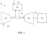
- FIG. 1 depicts a schematic view of an example gas turbine engine 10 as may be used herein.
- the gas turbine engine 10 may include a compressor 15.
- the compressor 15 compresses an incoming flow of air 20.
- the compressor 15 delivers the compressed flow of air 20 to a combustor 25.
- the combustor 25 mixes the compressed flow of air 20 with a compressed flow of fuel 30 and ignites the mixture to create a flow of combustion gases 35.
- the gas turbine engine 10 may include any number of combustors 25.
- the flow of combustion gases 35 is in turn delivered to a turbine 40.
- the flow of combustion gases 35 drives the turbine 40 so as to produce mechanical work.
- the mechanical work produced in the turbine 40 drives the compressor 15 via a shaft 45 and an external load 50 such as an electrical generator and the like.
- the gas turbine engine 10 may use natural gas, various types of syngas, and/or other types of fuels.
- the gas turbine engine 10 may be any one of a number of different gas turbine engines offered by General Electric Company of Schenectady, New York, including, but not limited to, those such as a 7 or a 9 series heavy duty gas turbine engine and the like.
- the gas turbine engine 10 may have different configurations and may use other types of components.
- Other types of gas turbine engines also may be used herein.
- Multiple gas turbine engines, other types of turbines, and other types of power generation equipment also may be used herein together.
- FIGS. 2-8 depict systems and methods for inspecting a blade or vane in a turbomachine, such as a compressor or turbine in a gas turbine engine. Any industrial or aviation turbomachine may be inspected.
- a scanner 100 may be attachable to a trailing edge 102 of a blade 104.
- the scanner 100 includes a main body 106 having a clamp 108 attachable to the trailing edge 102 of the blade 104.
- the clamp 108 may include two clamps attachable to opposite ends of the trailing edge 102 of the blade 104.
- a first clamp 110 may be attached to a radially outer portion of the trailing edge 102 of the blade 104
- a second clamp 112 may be attached to a radially inner portion of the trailing edge 102 of the blade 104.
- the first clamp 110 and the second clamp 112 may open and close on the trailing edge 102 of the blade 104 in order to secure the scanner 100 thereto.
- the main body 106 may be a segmented structure. That is, the main body 106 may include a number of segments pivotally attached together. For example, a first segment 114 may be attached to a second segment 116 via a pivot 118 such that the first segment 114 pivots relative to the second segment 116.
- the main body 106 many include any number of segments.
- the segments may be any suitable size, shape, or configuration.
- the segmented structure of the main body 106 may enable the scanner to be maneuvered and operated between the various stages of the turbomachine to a desired location, as depicted in FIG. 5 .
- the scanner 100 includes a first flexible arm 120 moveably attached to the main body 106.
- the first arm 120 may be made of spring steel so as to flex about a profile of the blade 104.
- the first arm 120 may bend about the contour of a first side 122 of the blade 104.
- the first arm 120 may be any suitable size, shape, or configuration.
- the first arm 120 may move relative to the main body 106.
- the first arm 120 may move in the axial direction, as indicated by the arrow 124.
- the first arm 120 may move in the radial direction, as indicated by the arrow 126.
- the first arm 120 may include a first probe 128 attached to an end thereof. Any number of probes may be used.
- the first arm 120 may include an upper probe disposed radially outward of a lower probe.
- the scanner 100 may include four total probes, such as an upper and a lower eddy current probe for each side of the blade or vane.
- the wall thickness of the component may vary radially, and thus may require a different probe to inspect the lower part of a blade/vane than for the upper part. Also surface coverage and radial reach may be affected by the specific probe configuration.
- the probes may be attached to the probe holder using a set of passive joints to provide a gimbal (e.g., allow the probes to adapt to the blade/vane surface geometry).
- a probe holder may hold a number of probes.
- the first probe 128 may be pivotally attached to the first arm 120 via a pivot 130.
- the first probe 128 may be moved about the first side 122 (e.g., the pressure side) of the blade 104 to inspect the blade 104.
- the first probe 128 may slide about the first side 122 of the blade 104 about one or more rollers 132 as the first arm 120 moves the first probe 128 in the radial 126 and/or axial 124 directions. In this manner, the first probe 128 may be moved about any location on the surface of the first side 122 of the blade 104.
- the rollers 132 may be omitted.
- the first probe 128 may use eddy current or ultrasonic sensors to inspect the blade.
- the first probe 128 may be any suitable size, shape, or configuration.
- the first probe 128 may include any type of sensor, camera, or the like.
- the scanner 100 includes a second flexible arm 134 moveably attached to the main body 106.
- the second arm 134 may be made of spring steel so as to flex about a profile of the blade 104.
- the second arm 134 may bend about the contour of a second side 136 of the blade 104.
- the second arm 134 may be any suitable size, shape, or configuration.
- the second arm 134 may move relative to the main body 106.
- the second arm 134 may move in the axial direction 124.
- the second arm 134 may move in the radial direction 126.
- the second arm 134 may include a second probe 138 attached to an end thereof. Any number of probes may be used.
- the second arm 134 may include an upper probe disposed radially outward of a lower probe.
- the scanner 100 may include four total probes, such as an upper and a lower eddy current probe for each side of the blade or vane.
- the wall thickness of the component may vary radially, and thus may require a different probe to inspect the lower part of a blade/vane than for the upper part. Also surface coverage and radial reach may be affected by the specific probe configuration.
- the probes may be attached to the probe holder using a set of passive joints to provide a gimbal (e.g., allow the probes to adapt to the blade/vane surface geometry).
- a probe holder may hold a number of probes.
- the second probe 138 may be pivotally attached to the second arm 138 via a pivot 140.
- the second probe 138 may be moved about the second side 136 (e.g., the suction side) of the blade 104 to inspect the blade 104.
- the second probe 138 may slide about the second side 136 of the blade 104 about one or more rollers 142 as the second arm 134 moves the second probe 138 in the radial 126 and/or axial 124 directions.
- the second probe 138 may be moved about any location on the surface of the second side 136 of the blade 104.
- the rollers 142 may be omitted.
- the second probe 138 may use eddy current or ultrasonic sensors to inspect the blade 104.
- the second probe 138 may be any suitable size, shape, or configuration.
- the second probe 138 may include any type of sensor, camera, or the like.
- the scanner 100 includes a first axial actuator 144 in mechanical communication with the first arm 120, a second axial actuator 146 in mechanical communication with the second arm 134, and a radial actuator 148 in mechanical communication with the first arm 120 and the second arm 134.
- the first arm 120 and the second arm 134 may move in unison in the radial direction 126. That is, a single actuator (i.e., the radial actuator 148) may move the first arm 120 and the second arm 134 at the same time.
- the first arm 120 and the second arm 134 may be capable of moving in the axial direction 124 independently of each other.
- first axial actuator 144 may move the first arm 120 in the axial direction 124
- second axial actuator 146 may move the second arm 134 in the axial direction 124.
- first probe 128 and the second probe 138 may move separately or in parallel in the axial direction 126.
- the first arm 120 and the second arm 134 may include respective radial actuators for independent and separate movement thereof in the radial direction 126.
- the scanner 100 configuration enables the pressure side and the suction side of the blade 104 to be inspected at the same time. That is, the first probe 128 and the second probe 138 may move along the respective surface of the blade at the same time.
- the various actuators discussed herein may be in electrical communication with one or more controllers.
- one or more sensors and/or probes may be in electrical communication with the controllers.
- the controllers may be located onboard of the scanner 100 or remotely located.
- the scanner 100 may be hardwired or wirelessly connected over a network to one or more computing devices and/or controllers for controlling the actuation of the various components of the scanner 100.
- the one or more computing devices and/or controllers may be located on the scanner 100 or remote thereof.
- the locations of the first probe 128 and the second probe 138 may be verified by one or more sensors (e.g., proximity sensors) located on the scanner 100.
- the scanner may include integrated sensors (e.g. proximity sensors, encoders, cameras etc.) used to reconstruct the position of the probes on the blade and/or vanes.
- one or more calibration methods may be performed periodically to ensure the scanner 100 operates as intended and that the location of the first probe 128 and the second probe 138 is correct.
- the first axial actuator 144 and the second axial actuator 146 may be linear track actuators.
- the first axial actuator 144 may include a first track 150
- the second axial actuator 146 may include a second track 152.
- the first track 150 and the second track 152 may be disposed in a respective groove 154 in the first segment 114 of the main body 106.
- the first track 150 and the second track 152 may move in the axial direction 124 via a respective motor 156 disposed on the second segment 116 of the main body 106. Any suitable type and number of actuators may be used herein.
- the radial actuator 148 may be a linear screw actuator.
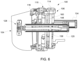
- the first arm 120 and the second arm 134 may include a nut 158 attached to a rotatable screw shaft 160, as depicted in FIGS. 3 and 6 . In this manner, as the rotatable screw shaft 160 rotates, the first arm 120 and the second arm 134 may move up and down along the rotatable screw shaft 160 in the radial direction 126. Any suitable type and number of actuators may be used herein.
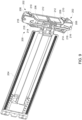
- FIGS. 7 and 8 depict the scanner 100 attached to a robotic device 162, e.g., a robotic vehicle (also known as a scanner deployment device) configured to maneuver the scanner 100 between the various stages of the turbomachine to a desired location.
- a robotic vehicle also known as a scanner deployment device
- the scanner 100 may be maneuvered through the various stages of the compressor or turbine to a desired location adjacent to a blade or vane to be inspected.
- the scanner 100 may be attached to the blade or vane.
- the scanner may be detached from the deployment device once attached to the blade and/or vane.
- the deployment device may retract and deploy other scanners to other blades and/or vanes.
- the scanner may be attached to the deployment device during the entire inspection process.
- the arms may move the probes about the pressure and suction side surfaces of the blade or vane.
- the scanner 100 enables the blades or vanes to be inspected without having to dismantle the turbomachine. Instead, the scanner 100 may, for example, be inserted into and traverse along the hot gas path of a turbine or compressor to the blades or vanes to be inspected.
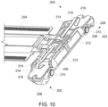
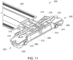
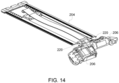
- FIGS. 9-14 depict an example embodiment of a liftoff mechanism 200 for moving (i.e., pivoting) one or more probes 202 attached to an arm 204 between a first configuration and a second configuration in order to calibrate the probes 202.
- the liftoff mechanism 200 may be incorporated into the embodiments disclosed in FIGS. 1-8 . That is, the arm 204 and probes 202 may be employed as the first arm 128, the second arm 134, the first probe 128, and/or the second probe 138.
- the probes 202 may include a main body 206 and a probe portion 208.
- the main body 206 may be pivotally attached to the arm 204.
- the pivot joints 220 may enable each individual main body 206 to pivot relative to the arm 204 independent of the other main body 206.
- the pivot joints 220 may be passive spring loaded joints for maintaining the probe portions in contact with a surface of the blade and/or vane.
- the probe portion 208 may include one or more probes or sensors that may be movably attached to the main body 206 via a pivot 210. That is, the probe portion 208 may pivot relative to the main body 206 about the pivot 210.
- each probe 202 may be in mechanical communication with an actuator, such as a motor 212.
- the motor 212 may comprise a pulse-width modulation (PWM) servo motor. Any suitable actuator may be used herein.
- the motor 212 may be integrated into the main body 206 of the probe 202. That is, the motor 212 may be disposed or housed within the main body 206.
- the motor 212 may be attached to the probe portion 208 via a linkage 214.
- the motor 212 When the motor 212 is activated, it may move the linkage 214, which in turn may pivot the probe portion 208 about the pivot 210 between a first configuration (as depicted in FIG. 13 ) and a second configuration (as depicted in FIG. 12 ).
- the probe portion 208 In the first configuration, the probe portion 208 may be in contact with (or "on") the surface of the blade or vane.
- the probe portions 208 may not be in contact with (or "off") the surface of the blade or vane. In this manner, the motor 212 and linkage 214 may pivot the probe portion 208 about the pivot 210 between the on and off positions.
- the liftoff mechanism 200 may enable the calibration of the probes 202.
- calibrating the probes 202 may involve collecting a series of electrical signals with the probes 202 in the first configuration (i.e., "on” the surface of the blade or vane) and in the second configuration (i.e., "off' the surface of the blade or vane) both before, during, and after operation of the scanner 100.
- calibration settings may then be determined.
- the calibration procedure is designed to set the sensitivity of the probes 202 so that the subsequent readings are more accurate in determining inclusions or damages to the blade or vane surfaces.
- the calibration of the probes 202 may be checked in the "off' configuration after operation of the scanner 100 to enable an operator to determine if the scanner 100 has performed constantly throughout the blade or vane inspection by comparing any difference between the before and after calibration readings.
- the probes 202 may include printed circuit boards 216 (PCBs) for providing electrical pathways from the probes 202 to a controller or the like.
- the PCBs 216 may be in electrical communication with one another and/or a controller via one or more electrical connections 218. Due to the pivoting movement of the probes 202, the electrical connections 218 may comprise flexible wires or the like.
- each probe 202 may be movable independently due to the activation of various actuators and the changing surface of the blade or vane geometry. More so, in order to calibrate the probes 202 when in the "off' position (i.e., away from the surface of the blade or vane), the servo motor 212 may be activated via a controller to rotate the linkage 214, which may pivot and "lift” the probe portion 208 away from the blade or vane surface, as shown in FIG. 12 . Once the calibration signal is recorded in the "off' configuration, the servo motor 212 may return to its start position, which may pivot the probe portion 208 to reengage the blade or vane surface, as shown in FIG 13 .
- the liftoff mechanism 200 enables a user to execute a remote calibration procedure before and after every blade or vane inspection.
Description
- The disclosure relates generally to turbomachinery and more particularly relates to systems and methods for inspecting blades or vanes in turbomachinery.
- Turbomachinery components, such as blades and vanes, are difficult to inspect due to space restrictions. Current techniques for accessing and inspecting the blades and vanes include at least partially dismantling the turbomachinery. This can be time consuming and costly. Consequently, there is a need to provide more extensive and regular integrity assessments of the turbomachinery components that are affordable and feasible.
-
US 2009/078742 A1 relates to a method and a device for inspecting a pipe connection weld by an ultrasound probe.JP S58 79153 A DE 27 33 946 A1 relates to a manipulator for ultrasonic weld inspection of a reactor duct.JP S62 180265 A - According to the invention there is disclosed a scanner for inspecting a component. The scanner includes a main body having a clamp attachable to a trailing edge of the component, a first flexible arm moveably attached to the main body about a first side of the component, and a first probe pivotally attached to the first flexible arm. The first probe is configured to slide along the first side of the component. A first axial actuator is in mechanical communication with the first flexible arm. The scanner also includes a second flexible arm moveably attached to the main body about a second side of the component, with a second probe pivotally attached to the second flexible arm. The second probe is configured to slide along the second side of the component. A second axial actuator is in mechanical communication with the second flexible arm. In addition, a radial actuator is in mechanical communication with the first flexible arm and the second flexible arm.
- Other embodiments, aspects, and features of the disclosure will become apparent to those skilled in the art from the following detailed description, the accompanying drawings, and the appended claims.
- Reference will now be made to the accompanying drawings, which are not necessarily drawn to scale.
-
FIG. 1 depicts of an example gas turbine engine according to an embodiment. -
FIG. 2 depicts a scanner attached to a blade according to an embodiment. -
FIG. 3 depicts a scanner attached to a blade according to an embodiment. -
FIG. 4 depicts a scanner attached to a blade according to an embodiment. -
FIG. 5 depicts a scanner attached to a blade according to an embodiment. -
FIG. 6 depicts a scanner attached to a blade according to an embodiment. -
FIG. 7 depicts a scanner attachable to a robotic vehicle according to an embodiment. -
FIG. 8 depicts a scanner attachable to a robotic vehicle according to an embodiment. -
FIG. 9 depicts a liftoff mechanism according to an embodiment. -
FIG. 10 depicts a liftoff mechanism according to an embodiment. -
FIG. 11 depicts a liftoff mechanism according to an embodiment. -
FIG. 12 depicts a liftoff mechanism according to an embodiment. -
FIG. 13 depicts a liftoff mechanism according to an embodiment. -
FIG. 14 depicts a liftoff mechanism according to an embodiment. - The systems and methods described herein may be used to inspect blades or vanes (or any other component) in a turbomachine. The blades or vanes may be disposed in a compressor or a turbine. Any device with blades or vanes may utilize the systems and methods disclosed herein to inspect the blades or vanes. In some instances, the turbomachine may be a gas turbine engine. Any industrial or aviation turbomachine may be used.
- Referring now to the drawings, in which like numerals refer to like elements throughout the several views,
FIG. 1 depicts a schematic view of an example gas turbine engine 10 as may be used herein. The gas turbine engine 10 may include a compressor 15. The compressor 15 compresses an incoming flow of air 20. The compressor 15 delivers the compressed flow of air 20 to a combustor 25. The combustor 25 mixes the compressed flow of air 20 with a compressed flow of fuel 30 and ignites the mixture to create a flow of combustion gases 35. Although only a single combustor 25 is shown, the gas turbine engine 10 may include any number of combustors 25. The flow of combustion gases 35 is in turn delivered to a turbine 40. The flow of combustion gases 35 drives the turbine 40 so as to produce mechanical work. The mechanical work produced in the turbine 40 drives the compressor 15 via a shaft 45 and an external load 50 such as an electrical generator and the like. - The gas turbine engine 10 may use natural gas, various types of syngas, and/or other types of fuels. The gas turbine engine 10 may be any one of a number of different gas turbine engines offered by General Electric Company of Schenectady, New York, including, but not limited to, those such as a 7 or a 9 series heavy duty gas turbine engine and the like. The gas turbine engine 10 may have different configurations and may use other types of components. Other types of gas turbine engines also may be used herein. Multiple gas turbine engines, other types of turbines, and other types of power generation equipment also may be used herein together.
-
FIGS. 2-8 depict systems and methods for inspecting a blade or vane in a turbomachine, such as a compressor or turbine in a gas turbine engine. Any industrial or aviation turbomachine may be inspected. As depicted inFIG. 2 , a scanner 100 may be attachable to a trailing edge 102 of a blade 104. The scanner 100 includes a main body 106 having a clamp 108 attachable to the trailing edge 102 of the blade 104. In some instances, the clamp 108 may include two clamps attachable to opposite ends of the trailing edge 102 of the blade 104. For example, a first clamp 110 may be attached to a radially outer portion of the trailing edge 102 of the blade 104, and a second clamp 112 may be attached to a radially inner portion of the trailing edge 102 of the blade 104. The first clamp 110 and the second clamp 112 may open and close on the trailing edge 102 of the blade 104 in order to secure the scanner 100 thereto. - In some instances, the main body 106 may be a segmented structure. That is, the main body 106 may include a number of segments pivotally attached together. For example, a first segment 114 may be attached to a second segment 116 via a pivot 118 such that the first segment 114 pivots relative to the second segment 116. The main body 106 many include any number of segments. The segments may be any suitable size, shape, or configuration. As a result, the segmented structure of the main body 106 may enable the scanner to be maneuvered and operated between the various stages of the turbomachine to a desired location, as depicted in
FIG. 5 . - According to the invention, the scanner 100 includes a first flexible arm 120 moveably attached to the main body 106. In one example, the first arm 120 may be made of spring steel so as to flex about a profile of the blade 104. For example, the first arm 120 may bend about the contour of a first side 122 of the blade 104. The first arm 120 may be any suitable size, shape, or configuration. As noted above, the first arm 120 may move relative to the main body 106. According to the invention, the first arm 120 may move in the axial direction, as indicated by the arrow 124. In addition, the first arm 120 may move in the radial direction, as indicated by the arrow 126.
- The first arm 120 may include a first probe 128 attached to an end thereof. Any number of probes may be used. For example, the first arm 120 may include an upper probe disposed radially outward of a lower probe. In this manner, the scanner 100 may include four total probes, such as an upper and a lower eddy current probe for each side of the blade or vane. The wall thickness of the component may vary radially, and thus may require a different probe to inspect the lower part of a blade/vane than for the upper part. Also surface coverage and radial reach may be affected by the specific probe configuration. The probes may be attached to the probe holder using a set of passive joints to provide a gimbal (e.g., allow the probes to adapt to the blade/vane surface geometry). A probe holder may hold a number of probes.
- In some instances, the first probe 128 may be pivotally attached to the first arm 120 via a pivot 130. The first probe 128 may be moved about the first side 122 (e.g., the pressure side) of the blade 104 to inspect the blade 104. For example, the first probe 128 may slide about the first side 122 of the blade 104 about one or more rollers 132 as the first arm 120 moves the first probe 128 in the radial 126 and/or axial 124 directions. In this manner, the first probe 128 may be moved about any location on the surface of the first side 122 of the blade 104. In certain embodiments, the rollers 132 may be omitted. In some instances, the first probe 128 may use eddy current or ultrasonic sensors to inspect the blade. The first probe 128 may be any suitable size, shape, or configuration. The first probe 128 may include any type of sensor, camera, or the like.
- As depicted in
FIGS. 4 and7 , and according to the invention, the scanner 100 includes a second flexible arm 134 moveably attached to the main body 106. In one example, the second arm 134 may be made of spring steel so as to flex about a profile of the blade 104. For example, the second arm 134 may bend about the contour of a second side 136 of the blade 104. The second arm 134 may be any suitable size, shape, or configuration. As noted above, the second arm 134 may move relative to the main body 106. For example, the second arm 134 may move in the axial direction 124. In addition, the second arm 134 may move in the radial direction 126. - The second arm 134 may include a second probe 138 attached to an end thereof. Any number of probes may be used. For example, the second arm 134 may include an upper probe disposed radially outward of a lower probe. In this manner, the scanner 100 may include four total probes, such as an upper and a lower eddy current probe for each side of the blade or vane. The wall thickness of the component may vary radially, and thus may require a different probe to inspect the lower part of a blade/vane than for the upper part. Also surface coverage and radial reach may be affected by the specific probe configuration. The probes may be attached to the probe holder using a set of passive joints to provide a gimbal (e.g., allow the probes to adapt to the blade/vane surface geometry). A probe holder may hold a number of probes. In some instances, the second probe 138 may be pivotally attached to the second arm 138 via a pivot 140. The second probe 138 may be moved about the second side 136 (e.g., the suction side) of the blade 104 to inspect the blade 104. For example, the second probe 138 may slide about the second side 136 of the blade 104 about one or more rollers 142 as the second arm 134 moves the second probe 138 in the radial 126 and/or axial 124 directions. In this manner, the second probe 138 may be moved about any location on the surface of the second side 136 of the blade 104. In certain embodiments, the rollers 142 may be omitted. In some instances, the second probe 138 may use eddy current or ultrasonic sensors to inspect the blade 104. The second probe 138 may be any suitable size, shape, or configuration. The second probe 138 may include any type of sensor, camera, or the like.
- As depicted in
FIGS. 2 and7 , and according to the invention, the scanner 100 includes a first axial actuator 144 in mechanical communication with the first arm 120, a second axial actuator 146 in mechanical communication with the second arm 134, and a radial actuator 148 in mechanical communication with the first arm 120 and the second arm 134. In this manner, the first arm 120 and the second arm 134 may move in unison in the radial direction 126. That is, a single actuator (i.e., the radial actuator 148) may move the first arm 120 and the second arm 134 at the same time. The first arm 120 and the second arm 134, however, may be capable of moving in the axial direction 124 independently of each other. That is, the first axial actuator 144 may move the first arm 120 in the axial direction 124, and the second axial actuator 146 may move the second arm 134 in the axial direction 124. In this manner, the first probe 128 and the second probe 138 may move separately or in parallel in the axial direction 126. In other instances, the first arm 120 and the second arm 134 may include respective radial actuators for independent and separate movement thereof in the radial direction 126. The scanner 100 configuration enables the pressure side and the suction side of the blade 104 to be inspected at the same time. That is, the first probe 128 and the second probe 138 may move along the respective surface of the blade at the same time. - The various actuators discussed herein, including the first axial actuator 144, the second axial actuator 146, and the radial actuator 148, may be in electrical communication with one or more controllers. In addition, one or more sensors and/or probes may be in electrical communication with the controllers. The controllers may be located onboard of the scanner 100 or remotely located. For example, the scanner 100 may be hardwired or wirelessly connected over a network to one or more computing devices and/or controllers for controlling the actuation of the various components of the scanner 100. The one or more computing devices and/or controllers may be located on the scanner 100 or remote thereof. The locations of the first probe 128 and the second probe 138 may be verified by one or more sensors (e.g., proximity sensors) located on the scanner 100. For example, the scanner may include integrated sensors (e.g. proximity sensors, encoders, cameras etc.) used to reconstruct the position of the probes on the blade and/or vanes. In addition, as discussed below, one or more calibration methods may be performed periodically to ensure the scanner 100 operates as intended and that the location of the first probe 128 and the second probe 138 is correct.
- In certain embodiments, the first axial actuator 144 and the second axial actuator 146 may be linear track actuators. For example, the first axial actuator 144 may include a first track 150, and the second axial actuator 146 may include a second track 152. The first track 150 and the second track 152 may be disposed in a respective groove 154 in the first segment 114 of the main body 106. The first track 150 and the second track 152 may move in the axial direction 124 via a respective motor 156 disposed on the second segment 116 of the main body 106. Any suitable type and number of actuators may be used herein.
- In certain embodiments, the radial actuator 148 may be a linear screw actuator. For example, the first arm 120 and the second arm 134 may include a nut 158 attached to a rotatable screw shaft 160, as depicted in
FIGS. 3 and6 . In this manner, as the rotatable screw shaft 160 rotates, the first arm 120 and the second arm 134 may move up and down along the rotatable screw shaft 160 in the radial direction 126. Any suitable type and number of actuators may be used herein. -
FIGS. 7 and8 depict the scanner 100 attached to a robotic device 162, e.g., a robotic vehicle (also known as a scanner deployment device) configured to maneuver the scanner 100 between the various stages of the turbomachine to a desired location. In this manner, the scanner 100 may be maneuvered through the various stages of the compressor or turbine to a desired location adjacent to a blade or vane to be inspected. Once there, the scanner 100 may be attached to the blade or vane. In some instances, the scanner may be detached from the deployment device once attached to the blade and/or vane. In such instances, the deployment device may retract and deploy other scanners to other blades and/or vanes. In other instances, the scanner may be attached to the deployment device during the entire inspection process. Once attached to the blade and/or vane, the arms may move the probes about the pressure and suction side surfaces of the blade or vane. The scanner 100 enables the blades or vanes to be inspected without having to dismantle the turbomachine. Instead, the scanner 100 may, for example, be inserted into and traverse along the hot gas path of a turbine or compressor to the blades or vanes to be inspected. -
FIGS. 9-14 depict an example embodiment of a liftoff mechanism 200 for moving (i.e., pivoting) one or more probes 202 attached to an arm 204 between a first configuration and a second configuration in order to calibrate the probes 202. In some instances, the liftoff mechanism 200 may be incorporated into the embodiments disclosed inFIGS. 1-8 . That is, the arm 204 and probes 202 may be employed as the first arm 128, the second arm 134, the first probe 128, and/or the second probe 138. - The probes 202 may include a main body 206 and a probe portion 208. In certain embodiment, the main body 206 may be pivotally attached to the arm 204. For example, as depicted in
FIG. 14 , the pivot joints 220 may enable each individual main body 206 to pivot relative to the arm 204 independent of the other main body 206. In some instances, the pivot joints 220 may be passive spring loaded joints for maintaining the probe portions in contact with a surface of the blade and/or vane. In some instances, the probe portion 208 may include one or more probes or sensors that may be movably attached to the main body 206 via a pivot 210. That is, the probe portion 208 may pivot relative to the main body 206 about the pivot 210. In order to pivot the probe portion 208, each probe 202 may be in mechanical communication with an actuator, such as a motor 212. In some instances, the motor 212 may comprise a pulse-width modulation (PWM) servo motor. Any suitable actuator may be used herein. In certain embodiment, the motor 212 may be integrated into the main body 206 of the probe 202. That is, the motor 212 may be disposed or housed within the main body 206. - In certain embodiments, the motor 212 may be attached to the probe portion 208 via a linkage 214. When the motor 212 is activated, it may move the linkage 214, which in turn may pivot the probe portion 208 about the pivot 210 between a first configuration (as depicted in
FIG. 13 ) and a second configuration (as depicted inFIG. 12 ). In the first configuration, the probe portion 208 may be in contact with (or "on") the surface of the blade or vane. Conversely, in the second configuration, the probe portions 208 may not be in contact with (or "off") the surface of the blade or vane. In this manner, the motor 212 and linkage 214 may pivot the probe portion 208 about the pivot 210 between the on and off positions. - As noted above, the liftoff mechanism 200 may enable the calibration of the probes 202. For example, calibrating the probes 202 may involve collecting a series of electrical signals with the probes 202 in the first configuration (i.e., "on" the surface of the blade or vane) and in the second configuration (i.e., "off' the surface of the blade or vane) both before, during, and after operation of the scanner 100. Following an analysis of the "on" and "off' electrical signals, calibration settings may then be determined. The calibration procedure is designed to set the sensitivity of the probes 202 so that the subsequent readings are more accurate in determining inclusions or damages to the blade or vane surfaces. In some instances, the calibration of the probes 202 may be checked in the "off' configuration after operation of the scanner 100 to enable an operator to determine if the scanner 100 has performed constantly throughout the blade or vane inspection by comparing any difference between the before and after calibration readings.
- The probes 202 may include printed circuit boards 216 (PCBs) for providing electrical pathways from the probes 202 to a controller or the like. The PCBs 216 may be in electrical communication with one another and/or a controller via one or more electrical connections 218. Due to the pivoting movement of the probes 202, the electrical connections 218 may comprise flexible wires or the like.
- In this manner, as noted above, each probe 202 may be movable independently due to the activation of various actuators and the changing surface of the blade or vane geometry. More so, in order to calibrate the probes 202 when in the "off' position (i.e., away from the surface of the blade or vane), the servo motor 212 may be activated via a controller to rotate the linkage 214, which may pivot and "lift" the probe portion 208 away from the blade or vane surface, as shown in
FIG. 12 . Once the calibration signal is recorded in the "off' configuration, the servo motor 212 may return to its start position, which may pivot the probe portion 208 to reengage the blade or vane surface, as shown inFIG 13 . The liftoff mechanism 200 enables a user to execute a remote calibration procedure before and after every blade or vane inspection. - It should be apparent that the foregoing relates only to certain embodiments of the present application and the resultant patent. Numerous changes and modifications may be made herein by one of ordinary skill in the art without departing from the general scope of the invention as defined by the following claims. Although embodiments have been described in language specific to structural features and/or methodological acts, it is to be understood that the disclosure is not necessarily limited to the specific features or acts described. Rather, the specific features and acts are disclosed as illustrative forms of implementing the embodiments.
Claims (8)
- A scanner (100) for inspecting a component (104), the scanner comprising:a main body (106) comprising a clamp (108) attachable to a trailing edge (102) of the component (104);a first flexible arm (120) moveably attached to the main body (106) about a first side (122) of the component (104);a first probe (128) pivotally attached to the first flexible arm (120);a first axial actuator (144) in mechanical communication with the first flexible arm (120) so that the first probe (128) can slide along the first side (122) of the component (104);a second flexible arm (134) moveably attached to the main body (106) about a second side (136) of the component (104);a second probe (138) pivotally attached to the second flexible arm (134);a second axial actuator (146) in mechanical communication with the second flexible arm (134) so that the second probe (138) can slide along the second side (136) of the component (104); anda radial actuator (148) in mechanical communication with the first flexible arm (120) and the second flexible arm (134).
- The scanner (100) of claim 1, wherein the main body (106) comprises a segmented structure.
- The scanner (100) of claim 2, wherein the segmented structure comprises a plurality of segments (114, 116) pivotally attached together.
- The scanner (100) of claim 1, wherein the clamp (108) comprises two clamps (110, 112) attachable to the trailing edge (102) of the component (104).
- The scanner (100) of claim 1, wherein the first axial actuator (144) is a linear track actuator.
- The scanner (100) of claim 1, wherein the second axial actuator (146) is a linear track actuator.
- The scanner (100) of claim 1, wherein the radial actuator (148) is a linear screw actuator.
- The scanner (100) of claim 1, further comprising a liftoff mechanism (200) in mechanical communication with the first probe (128), the second probe (138), or a combination thereof for calibrating the first probe (128), the second probe (138), or a combination thereof.
Applications Claiming Priority (2)
| Application Number | Priority Date | Filing Date | Title |
|---|---|---|---|
| US15/635,626 US10451521B2 (en) | 2017-06-28 | 2017-06-28 | Systems and methods for inspecting blades or vanes in turbomachinery |
| PCT/US2018/034515 WO2019005373A2 (en) | 2017-06-28 | 2018-05-25 | Systems and methods for inspecting blades or vanes in turbomachinery |
Publications (3)
| Publication Number | Publication Date |
|---|---|
| EP3658880A2 EP3658880A2 (en) | 2020-06-03 |
| EP3658880A4 EP3658880A4 (en) | 2021-03-24 |
| EP3658880B1 true EP3658880B1 (en) | 2023-10-11 |
Family
ID=64738214
Family Applications (1)
| Application Number | Title | Priority Date | Filing Date |
|---|---|---|---|
| EP18823692.1A Active EP3658880B1 (en) | 2017-06-28 | 2018-05-25 | Systems and methods for inspecting blades or vanes in turbomachinery |
Country Status (3)
| Country | Link |
|---|---|
| US (1) | US10451521B2 (en) |
| EP (1) | EP3658880B1 (en) |
| WO (1) | WO2019005373A2 (en) |
Family Cites Families (13)
| Publication number | Priority date | Publication date | Assignee | Title |
|---|---|---|---|---|
| DE2733946C2 (en) * | 1977-07-27 | 1985-07-11 | Kraftwerk Union AG, 4330 Mülheim | Test manipulator for volumetric internal testing of the weld seams of nozzles and nozzle edges in pressure vessels |
| JPS5879153A (en) * | 1981-11-06 | 1983-05-12 | Tokyo Electric Power Co Inc:The | Guide rail |
| JPS62180265A (en) * | 1986-02-05 | 1987-08-07 | Hitachi Ltd | Ultrasonic flaw detecting device for curved tube |
| US6614872B2 (en) | 2001-01-26 | 2003-09-02 | General Electric Company | Method and apparatus for localized digital radiographic inspection |
| US20060213274A1 (en) | 2005-03-22 | 2006-09-28 | Siemens Westinghouse Power Corporation | Nondestructive inspection heads for components having limited surrounding space |
| US7543512B2 (en) * | 2005-04-13 | 2009-06-09 | General Electric Company | Bore inspection probe |
| FR2888327B1 (en) * | 2005-07-05 | 2008-07-04 | Saipem S A Sa | METHOD AND DEVICE FOR CONTROLLING ULTRASOUND PROBE CONNECTION WELDING CONNECTION |
| US8347746B2 (en) | 2010-01-19 | 2013-01-08 | The Boeing Company | Crawling automated scanner for non-destructive inspection of aerospace structural elements |
| GB2496903B (en) | 2011-11-28 | 2015-04-15 | Rolls Royce Plc | An apparatus and a method of inspecting a turbomachine |
| EP2700811A1 (en) | 2012-08-23 | 2014-02-26 | Siemens Aktiengesellschaft | A device for repairing a wind turbine blade |
| EP2727843B1 (en) | 2012-10-30 | 2020-07-01 | The Boeing Company | Apparatus for automated maintenance of aircraft structural elements |
| US9810098B2 (en) | 2014-07-11 | 2017-11-07 | General Electric Company | System and method for inspecting turbomachines |
| US9625286B2 (en) | 2015-01-09 | 2017-04-18 | Olympus Scientific Solutions Americas Inc. | Adjustable probe holder assembly for an inspection sensor |
-
2017
- 2017-06-28 US US15/635,626 patent/US10451521B2/en active Active
-
2018
- 2018-05-25 WO PCT/US2018/034515 patent/WO2019005373A2/en unknown
- 2018-05-25 EP EP18823692.1A patent/EP3658880B1/en active Active
Also Published As
| Publication number | Publication date |
|---|---|
| US20190003925A1 (en) | 2019-01-03 |
| WO2019005373A3 (en) | 2019-02-07 |
| EP3658880A2 (en) | 2020-06-03 |
| EP3658880A4 (en) | 2021-03-24 |
| US10451521B2 (en) | 2019-10-22 |
| WO2019005373A2 (en) | 2019-01-03 |
Similar Documents
| Publication | Publication Date | Title |
|---|---|---|
| CN110073079B (en) | Maintenance apparatus and method for maintaining a turbine assembly | |
| US20200393328A1 (en) | Wireless antenna system for sensors on circumferential interior surface of turbomachine casing | |
| US20070089545A1 (en) | Methods and apparatus for rotary machinery inspection | |
| US11103964B2 (en) | Service apparatus for use with rotary machines | |
| CA3094679C (en) | Insertion apparatus for use with rotary machines | |
| EP2056102A2 (en) | Eddy current probe and methods of assembling the same | |
| US10822997B2 (en) | Inspection tool and method | |
| EP3933169A2 (en) | Insertion tool for a gas turbine engine | |
| EP2546643A2 (en) | Apparatus for inspecting turbomachine components in-situ | |
| CN104583539A (en) | Apparatus and method for servicing turbomachinery components in-situ | |
| US20200393524A1 (en) | Automated inspection for internal corrosion | |
| US20230271723A1 (en) | Inspection and repair tool | |
| US11179820B2 (en) | Mounting system for tool for machining circumferential interior surface of turbomachine casing | |
| CN110691890B (en) | Maintenance device for use with a rotating machine | |
| EP3658880B1 (en) | Systems and methods for inspecting blades or vanes in turbomachinery | |
| EP3808944A1 (en) | Maintenance system with tubular assembly for servicing a turbomachine | |
| US11519298B2 (en) | Sensor mounting for circumferential interior surface of turbomachine casing | |
| US11952907B2 (en) | Systems and methods for sensors on only part of circumferential interior surface of turbomachine casing | |
| EP3859126A1 (en) | Gas turbine engine inspection and maintenance tool | |
| EP2636857A1 (en) | A system for testing vanes of a turbomachine | |
| EP3816396A2 (en) | Insertion apparatus for use with rotary machines | |
| US11608756B2 (en) | Service apparatus for use with rotary machines | |
| EP3961187A1 (en) | Automated inspection for internal corrosion | |
| EP4249731A1 (en) | Multi-stage inspection systems and methods |
Legal Events
| Date | Code | Title | Description |
|---|---|---|---|
| STAA | Information on the status of an ep patent application or granted ep patent |
Free format text: STATUS: THE INTERNATIONAL PUBLICATION HAS BEEN MADE |
|
| PUAI | Public reference made under article 153(3) epc to a published international application that has entered the european phase |
Free format text: ORIGINAL CODE: 0009012 |
|
| STAA | Information on the status of an ep patent application or granted ep patent |
Free format text: STATUS: REQUEST FOR EXAMINATION WAS MADE |
|
| 17P | Request for examination filed |
Effective date: 20191227 |
|
| AK | Designated contracting states |
Kind code of ref document: A2 Designated state(s): AL AT BE BG CH CY CZ DE DK EE ES FI FR GB GR HR HU IE IS IT LI LT LU LV MC MK MT NL NO PL PT RO RS SE SI SK SM TR |
|
| AX | Request for extension of the european patent |
Extension state: BA ME |
|
| DAV | Request for validation of the european patent (deleted) | ||
| DAX | Request for extension of the european patent (deleted) | ||
| A4 | Supplementary search report drawn up and despatched |
Effective date: 20210224 |
|
| RIC1 | Information provided on ipc code assigned before grant |
Ipc: G01M 15/14 20060101ALI20210218BHEP Ipc: G01N 29/265 20060101ALI20210218BHEP Ipc: F04D 29/32 20060101ALI20210218BHEP Ipc: G01M 5/00 20060101AFI20210218BHEP Ipc: G01N 29/22 20060101ALI20210218BHEP Ipc: F04D 27/00 20060101ALI20210218BHEP Ipc: G01M 13/00 20190101ALI20210218BHEP Ipc: F04D 29/54 20060101ALI20210218BHEP Ipc: F01D 21/00 20060101ALI20210218BHEP |
|
| GRAP | Despatch of communication of intention to grant a patent |
Free format text: ORIGINAL CODE: EPIDOSNIGR1 |
|
| STAA | Information on the status of an ep patent application or granted ep patent |
Free format text: STATUS: GRANT OF PATENT IS INTENDED |
|
| INTG | Intention to grant announced |
Effective date: 20230504 |
|
| GRAS | Grant fee paid |
Free format text: ORIGINAL CODE: EPIDOSNIGR3 |
|
| GRAA | (expected) grant |
Free format text: ORIGINAL CODE: 0009210 |
|
| STAA | Information on the status of an ep patent application or granted ep patent |
Free format text: STATUS: THE PATENT HAS BEEN GRANTED |
|
| AK | Designated contracting states |
Kind code of ref document: B1 Designated state(s): AL AT BE BG CH CY CZ DE DK EE ES FI FR GB GR HR HU IE IS IT LI LT LU LV MC MK MT NL NO PL PT RO RS SE SI SK SM TR |
|
| REG | Reference to a national code |
Ref country code: GB Ref legal event code: FG4D |
|
| REG | Reference to a national code |
Ref country code: CH Ref legal event code: EP |
|
| REG | Reference to a national code |
Ref country code: DE Ref legal event code: R096 Ref document number: 602018059277 Country of ref document: DE |
|
| REG | Reference to a national code |
Ref country code: IE Ref legal event code: FG4D |
|
| REG | Reference to a national code |
Ref country code: DE Ref legal event code: R081 Ref document number: 602018059277 Country of ref document: DE Owner name: GENERAL ELECTRIC TECHNOLOGY GMBH, CH Free format text: FORMER OWNER: GENERAL ELECTRIC COMPANY, SCHENECTADY, NY, US |
|
| RAP2 | Party data changed (patent owner data changed or rights of a patent transferred) |
Owner name: GENERAL ELECTRIC TECHNOLOGY GMBH |
|
| REG | Reference to a national code |
Ref country code: LT Ref legal event code: MG9D |
|
| REG | Reference to a national code |
Ref country code: NL Ref legal event code: MP Effective date: 20231011 |
|
| REG | Reference to a national code |
Ref country code: AT Ref legal event code: MK05 Ref document number: 1620660 Country of ref document: AT Kind code of ref document: T Effective date: 20231011 |
|
| REG | Reference to a national code |
Ref country code: GB Ref legal event code: 732E Free format text: REGISTERED BETWEEN 20240222 AND 20240228 |
|
| PG25 | Lapsed in a contracting state [announced via postgrant information from national office to epo] |
Ref country code: NL Free format text: LAPSE BECAUSE OF FAILURE TO SUBMIT A TRANSLATION OF THE DESCRIPTION OR TO PAY THE FEE WITHIN THE PRESCRIBED TIME-LIMIT Effective date: 20231011 |
|
| PG25 | Lapsed in a contracting state [announced via postgrant information from national office to epo] |
Ref country code: GR Free format text: LAPSE BECAUSE OF FAILURE TO SUBMIT A TRANSLATION OF THE DESCRIPTION OR TO PAY THE FEE WITHIN THE PRESCRIBED TIME-LIMIT Effective date: 20240112 |
|
| PG25 | Lapsed in a contracting state [announced via postgrant information from national office to epo] |
Ref country code: IS Free format text: LAPSE BECAUSE OF FAILURE TO SUBMIT A TRANSLATION OF THE DESCRIPTION OR TO PAY THE FEE WITHIN THE PRESCRIBED TIME-LIMIT Effective date: 20240211 |
|
| PG25 | Lapsed in a contracting state [announced via postgrant information from national office to epo] |
Ref country code: LT Free format text: LAPSE BECAUSE OF FAILURE TO SUBMIT A TRANSLATION OF THE DESCRIPTION OR TO PAY THE FEE WITHIN THE PRESCRIBED TIME-LIMIT Effective date: 20231011 |