EP3658744B1 - Annular barrier for small diameter wells - Google Patents
Annular barrier for small diameter wells Download PDFInfo
- Publication number
- EP3658744B1 EP3658744B1 EP18748883.8A EP18748883A EP3658744B1 EP 3658744 B1 EP3658744 B1 EP 3658744B1 EP 18748883 A EP18748883 A EP 18748883A EP 3658744 B1 EP3658744 B1 EP 3658744B1
- Authority
- EP
- European Patent Office
- Prior art keywords
- metal sleeve
- expandable metal
- metal structure
- annular barrier
- well tubular
- Prior art date
- Legal status (The legal status is an assumption and is not a legal conclusion. Google has not performed a legal analysis and makes no representation as to the accuracy of the status listed.)
- Active
Links
- 230000004888 barrier function Effects 0.000 title claims description 84
- 239000002184 metal Substances 0.000 claims description 248
- 238000007789 sealing Methods 0.000 claims description 15
- 239000000463 material Substances 0.000 claims description 12
- 238000002955 isolation Methods 0.000 claims description 7
- 238000000034 method Methods 0.000 claims description 7
- 239000012530 fluid Substances 0.000 description 17
- 238000004519 manufacturing process Methods 0.000 description 16
- 239000003921 oil Substances 0.000 description 11
- 239000007789 gas Substances 0.000 description 9
- XLYOFNOQVPJJNP-UHFFFAOYSA-N water Substances O XLYOFNOQVPJJNP-UHFFFAOYSA-N 0.000 description 5
- VNWKTOKETHGBQD-UHFFFAOYSA-N methane Chemical compound C VNWKTOKETHGBQD-UHFFFAOYSA-N 0.000 description 4
- 239000010779 crude oil Substances 0.000 description 2
- 239000003345 natural gas Substances 0.000 description 2
- 230000008961 swelling Effects 0.000 description 2
- 238000004804 winding Methods 0.000 description 2
- 239000004215 Carbon black (E152) Substances 0.000 description 1
- 230000015572 biosynthetic process Effects 0.000 description 1
- 230000001419 dependent effect Effects 0.000 description 1
- 238000005553 drilling Methods 0.000 description 1
- 229930195733 hydrocarbon Natural products 0.000 description 1
- 150000002430 hydrocarbons Chemical class 0.000 description 1
- 230000002706 hydrostatic effect Effects 0.000 description 1
- 239000011499 joint compound Substances 0.000 description 1
- 239000007788 liquid Substances 0.000 description 1
- 238000012986 modification Methods 0.000 description 1
- 230000004048 modification Effects 0.000 description 1
- 239000000126 substance Substances 0.000 description 1
Images
Classifications
-
- E—FIXED CONSTRUCTIONS
- E21—EARTH DRILLING; MINING
- E21B—EARTH DRILLING, e.g. DEEP DRILLING; OBTAINING OIL, GAS, WATER, SOLUBLE OR MELTABLE MATERIALS OR A SLURRY OF MINERALS FROM WELLS
- E21B33/00—Sealing or packing boreholes or wells
- E21B33/10—Sealing or packing boreholes or wells in the borehole
- E21B33/12—Packers; Plugs
- E21B33/1208—Packers; Plugs characterised by the construction of the sealing or packing means
- E21B33/1212—Packers; Plugs characterised by the construction of the sealing or packing means including a metal-to-metal seal element
-
- E—FIXED CONSTRUCTIONS
- E21—EARTH DRILLING; MINING
- E21B—EARTH DRILLING, e.g. DEEP DRILLING; OBTAINING OIL, GAS, WATER, SOLUBLE OR MELTABLE MATERIALS OR A SLURRY OF MINERALS FROM WELLS
- E21B33/00—Sealing or packing boreholes or wells
- E21B33/10—Sealing or packing boreholes or wells in the borehole
- E21B33/12—Packers; Plugs
- E21B33/1208—Packers; Plugs characterised by the construction of the sealing or packing means
-
- E—FIXED CONSTRUCTIONS
- E21—EARTH DRILLING; MINING
- E21B—EARTH DRILLING, e.g. DEEP DRILLING; OBTAINING OIL, GAS, WATER, SOLUBLE OR MELTABLE MATERIALS OR A SLURRY OF MINERALS FROM WELLS
- E21B33/00—Sealing or packing boreholes or wells
- E21B33/10—Sealing or packing boreholes or wells in the borehole
- E21B33/12—Packers; Plugs
- E21B33/124—Units with longitudinally-spaced plugs for isolating the intermediate space
-
- E—FIXED CONSTRUCTIONS
- E21—EARTH DRILLING; MINING
- E21B—EARTH DRILLING, e.g. DEEP DRILLING; OBTAINING OIL, GAS, WATER, SOLUBLE OR MELTABLE MATERIALS OR A SLURRY OF MINERALS FROM WELLS
- E21B33/00—Sealing or packing boreholes or wells
- E21B33/10—Sealing or packing boreholes or wells in the borehole
- E21B33/12—Packers; Plugs
- E21B33/127—Packers; Plugs with inflatable sleeve
- E21B33/1277—Packers; Plugs with inflatable sleeve characterised by the construction or fixation of the sleeve
-
- E—FIXED CONSTRUCTIONS
- E21—EARTH DRILLING; MINING
- E21B—EARTH DRILLING, e.g. DEEP DRILLING; OBTAINING OIL, GAS, WATER, SOLUBLE OR MELTABLE MATERIALS OR A SLURRY OF MINERALS FROM WELLS
- E21B33/00—Sealing or packing boreholes or wells
- E21B33/10—Sealing or packing boreholes or wells in the borehole
- E21B33/12—Packers; Plugs
- E21B33/128—Packers; Plugs with a member expanded radially by axial pressure
-
- E—FIXED CONSTRUCTIONS
- E21—EARTH DRILLING; MINING
- E21B—EARTH DRILLING, e.g. DEEP DRILLING; OBTAINING OIL, GAS, WATER, SOLUBLE OR MELTABLE MATERIALS OR A SLURRY OF MINERALS FROM WELLS
- E21B43/00—Methods or apparatus for obtaining oil, gas, water, soluble or meltable materials or a slurry of minerals from wells
- E21B43/02—Subsoil filtering
- E21B43/10—Setting of casings, screens, liners or the like in wells
- E21B43/103—Setting of casings, screens, liners or the like in wells of expandable casings, screens, liners, or the like
- E21B43/108—Expandable screens or perforated liners
Definitions
- the present invention relates to an annular barrier for being mounted as part of a well tubular metal structure for providing zonal isolation in a small diameter borehole downhole for isolating a first zone from a second zone.
- the present invention also relates to a well tubular metal structure having a plurality of tubular sections and at least one annular barrier according to the present invention, and to a completion method of preparing an annular barrier according to the present invention.
- Annular barriers for providing a zone isolation e.g. for isolating a hydrocarbon-containing zone from a water producing zone
- an isolating element such as an expandable metal sleeve surrounding the base pipe, such as the casing or liner, and are expanded by liquid from within the base pipe.
- an isolating element such as an expandable metal sleeve surrounding the base pipe, such as the casing or liner
- the base pipe such as the casing or liner
- the swelling of the swellable material is dependent on fluid content and temperature in the well and, most importantly, the deployment time from entering the well and until arrival at the determined position.
- the casing or well tubular metal structure gets stuck or is just much more difficult to deploy, resulting in the deployment time being much longer than planned, and in these cases, the swelling may occur too early and the barrier is then set too early.
- the space between the base pipe and the borehole wall is very narrow in order to maximise the inner diameter of the base and thus the production volume.
- the risk of the casing or well tubular metal structure getting stuck is even higher than in larger wells.
- annular barrier for being mounted as part of a well tubular metal structure for providing zonal isolation in a small diameter borehole downhole for isolating a first zone from a second zone, comprising:
- annular barrier for being mounted as part of a well tubular metal structure for providing zonal isolation in a small diameter borehole downhole for isolating a first zone from a second zone, the annular barrier having an inner face and comprising:
- first end of the first end part being connected “end to end” to the first end of the expandable metal sleeve
- the first end of the second end part being connected “end to end” to the second end of the expandable metal sleeve
- ends are abutting and welded together or connected by a threading or similar connection.
- the inner face of the expandable metal sleeve thereby forms part of the inner face of the annular barrier and when mounted to the well tubular metal structure forms part of the inner face of the well tubular metal structure.
- the expandable metal sleeve does not overlap a tubular section of the well tubular metal structure nor the end parts in its entire thickness or length.
- the annular barrier can be connected as part of any well tubular metal structure, and the well tubular metal structure can be made with a substantially smaller outer diameter and fit into small diameter wells than annular barriers with a base pipe and a surrounding sleeve.
- the expandable metal sleeve is tested for expansion up to a certain radial expansion and by having the interchangeable end parts; the tested and qualified expandable metal sleeve can fit a variety of different well tubular metal structures and can quickly be changed on the platform or rig with other end parts to fit the borehole.
- first end part, the second end part and the expandable metal sleeve may form one tubular section configured to be mounted as part of the well tubular metal structure.
- first and second end parts and the expandable metal sleeve are mounted in succession of each other.
- annular barrier may be without any enclosed space.
- the expandable metal sleeve and the first and second end parts are connected so that the inner face of the expandable metal sleeve and the inner faces of the first and second end parts constitute the inner face of the annular barrier configured to be in contact with a production fluid conveyed by the well tubular metal structure.
- the expandable metal sleeve may be arranged in a non-overlapping configuration with other sections of the annular barrier.
- the expandable metal sleeve may be arranged in a non-overlapping configuration with the end parts in an entire thickness and/or length of the expandable metal sleeve.
- the second end of the first end part may be provided with a female thread connection, and the second end of the second end part may be provided with a male thread connection.
- first and second end parts may be connected to the first and second ends of the expandable metal sleeve by means of a standard connection, such as a stub acme thread connection.
- sealing elements may be arranged on the outer face of the expandable metal sleeve.
- the expandable metal sleeve may have:
- the expandable metal sleeve may have an outer sleeve diameter in an unexpanded state, the unexpanded outer sleeve diameter being equal to or smaller than an outer diameter of the first and second end parts.
- sealing elements may be arranged in grooves in the outer face of the expandable metal sleeve.
- the expandable metal sleeve may be made of a material which is more pliant than the material of the first and second end parts.
- test standard ASTM D1457 Elongation can be used.
- the annular barrier as described above may further comprise a split ring-shaped retaining element, the split ring-shaped retaining element forming a back-up for the sealing element.
- the split ring-shaped retaining element may have more than one winding, so that when the expandable tubular is expanded from the first outer diameter to the second outer diameter, the split ring-shaped retaining element partly unwinds.
- the split ring-shaped retaining element may be arranged in an abutting manner to the sealing element.
- first and second end parts may be tubular and may have a maximum wall thickness which is larger than a maximum wall thickness of the expandable metal sleeve.
- the expandable metal sleeve may be welded to the first and second end parts.
- the expandable metal sleeve may have a length, and no tubular may be arranged within the expandable metal sleeve along the entire length of the expandable metal sleeve.
- Said expandable metal sleeves may be expanded by an internal fluid pressure in the well tubular metal structure.
- At least one of the tubular sections between the expandable metal sleeves may comprise an inflow section, a sensor section or a gas lift valve.
- the present invention also relates to a well tubular metal structure having a plurality of tubular sections and at least one annular barrier according to the present invention; wherein the first and second end parts and the expandable metal sleeve are mounted in succession with the plurality of tubular sections, so that the first end part and the second end part are arranged between the expandable metal sleeve and the tubular sections along an axial extension of the well tubular metal structure.
- first part, the second end part and the expandable metal sleeve may be connected so that the inner face of the expandable metal sleeve and the inner faces of the first and second end parts constitute the inner face of the annular barrier configured to be in contact with a production fluid conveyed by the well tubular metal structure.
- first part, the second end part and the expandable metal sleeve may be connected so that the inner face of the expandable metal sleeve and the inner faces of the first and second end parts constitute the inner face of the well tubular metal structure configured to be in contact with a production fluid conveyed by the well tubular metal structure.
- the expandable metal sleeve is arranged in a non-overlapping configuration with any one of the tubular sections of the well tubular metal structure.
- the expandable metal sleeve is arranged in a non-overlapping configuration with any element in an entire thickness and/or length of the expandable metal sleeve.
- the well tubular metal structure may have an inner face, and an inner face of the expandable metal sleeve may form part of the inner face of the well tubular metal structure.
- the well tubular metal structure has an inner face
- the expandable metal sleeve and the first and second end parts may be connected so that the inner face of the expandable metal sleeve and the inner faces of the first and second end parts constitute the inner face of the annular barrier and the inner face of the well tubular metal structure.
- a second annular barrier according to the present invention may be mounted as part of the well tubular metal structure, and a plurality of tubular sections may be mounted between the annular barriers.
- first end part may create a first distance between the expandable metal sleeve and one of the pluralities of tubular sections
- the second end part may create a second distance between the expandable metal sleeve and another one of the plurality of tubular sections.
- the expandable metal sleeve may not overlap any of the plurality of tubular sections.
- the expandable metal sleeve may have an outer sleeve diameter in an unexpanded state, the unexpanded outer sleeve diameter being equal to or smaller than an outer diameter of the tubular sections forming the well tubular metal structure.
- the well tubular metal structure may be a production casing or a velocity string.
- the present invention also relates to a downhole system comprising the well tubular metal structure according to the present invention and an expansion tool for isolating a part of the well tubular metal structure opposite the expandable metal sleeve for pressurising that part in order to expand the expandable metal sleeve.
- the present invention relates to a completion method of preparing an annular barrier according to the present invention before being mounted as part of the well tubular metal structure, said completion method comprising:
- the present invention relates to a completion method comprising:
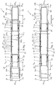
- Fig. 1 shows an annular barrier 1 for being mounted as part of a well tubular metal structure 100 for providing zonal isolation in a borehole downhole for isolating a first zone 101, e.g. producing oil or gas, from a second zone 102, e.g. producing water, as seen in Fig. 4 .
- Tubular sections of the well tubular metal structure are illustrated by dotted lines in Fig. 1 .
- the annular barrier 1 comprises an expandable metal sleeve 2 having a first end 3 and a second end 4 and an outer face 5 facing the borehole.
- the expandable metal sleeve 2 is shown in its unexpanded condition, and in order to provide zonal isolation, the expandable metal sleeve is expanded to a larger outer diameter by a hydraulic pressure from within to deform the expandable metal sleeve until the outer face presses towards the wall 50 (shown in Fig. 4 ) of the borehole.
- the annular barrier 1 further comprises a first end part 6 having a first end 7 connected to the first end of the expandable metal sleeve and a second end 8 for being mounted as part of the well tubular metal structure, and a second end part 9 having a first end 10 connected to the second end of the expandable metal sleeve and a second end 11 for being mounted as part of the well tubular metal structure.
- the first end 7 of the first end part 6 is connected “end to end” to the first end 3 of the expandable metal sleeve, so that part of the first end 7 overlaps part of the first end 3 and the ends of the parts connect end to end.
- the first end 10 of the second end part 9 is connected “end to end” to the second end 4 of the expandable metal sleeve, so that they form one tubular pipe.
- the second ends 8, 11 of the end parts are provided with an external thread (male thread connection) 20b or an internal thread (female thread connection) 20b for being mounted to corresponding external or internal threads of the well tubular metal structure.
- the well tubular metal structure can be made with a substantially smaller outer diameter and fit into small diameter wells than annular barriers with a base pipe and a surrounding sleeve.
- the expandable metal sleeve has a first section 26 having a first outer diameter OD 1 and a first thickness T 1 , and circumferential projections 27 having a thickness T 2 which is larger than the first thickness T 1 and having a second outer diameter OD 2 which is larger than the first outer diameter, so that when expanding the expandable metal sleeve, the first section bulges more radially outwards than the second section, resulting in the expandable metal sleeve 2 being strengthened in the expanded condition.
- the expandable metal sleeve does not need to expand as much as in larger diameter wells/boreholes, and therefore it is possible for the expandable metal sleeve of the "base-less" annular barrier to maintain the barrier function without the base pipe.
- the circumferential projections 27 increase the strength of the expanded expandable metal sleeve 2 when the expandable metal sleeve is not expanded more than required in small diameter wells/boreholes, so that the expandable metal sleeve can serve as both the base pipe and the barrier.
- the expandable metal sleeve therefore forms the well tubular metal structure.
- the annular barrier has an inner face 18 which is provided by the expandable metal sleeve 2, the first end part 6 and the second end part 9 so that an inner face 22 of the expandable metal sleeve, an inner face 19 of the first end part 6 and an inner face 23 of the second end part 9 constitute the inner face of the annular barrier.
- the inner face of expandable metal sleeve thereby forms part of the inner face of the annular barrier and when mounted to the well tubular metal structure forms part of the inner face of the well tubular metal structure.
- the expandable metal sleeve does not overlap a tubular metal part when seen in cross-section along the longitudinal extension of the well tubular metal structure and thus does not overlap any tubular section of the well tubular metal structure nor the end parts in the entire thickness or length of the expandable metal sleeve. Therefore, the first end part, the second end part and the expandable metal sleeve form one tubular pipe configured to be mounted as one part of the well tubular metal structure between two other tubular sections of the well tubular metal structure.
- the expandable metal sleeve is arranged in a non-overlapping configuration with the end parts in an entire thickness and/or length of the expandable metal sleeve, and also in a non-overlapping configuration with other sections of the annular barrier.
- the first and second end parts and the expandable metal sleeve are mounted in succession of each other in succession with the other tubular sections mounted together to form the well tubular metal structure.
- the annular barrier 1 may be without any enclosed space and the expansion and setting of the annular barrier may occur without the use of ejecting pressured fluid into such annular space known from known annular barriers.
- the expandable metal sleeve 2 is expanded by pressurising the inside in the annular barrier, e.g. by plugging the well tubular metal structure further down and pressurise from the top or isolate a section of the well tubular metal structure having one or more annular barriers and pressurise just that section.
- the expandable metal sleeve and the first and second end parts are connected so that the inner face of the expandable metal sleeve and the inner faces of the first and second end parts constitute the inner face of the annular barrier configured to be in contact with a production fluid conveyed by the well tubular metal structure when production is initiated.
- the second end 8 of the first end part 6 is provided with a female thread connection, i.e. an internal thread 20b
- the second end 11 of the second end part 9 is provided with a male thread connection, i.e. an external thread 20a.
- the female thread part i.e. the female thread connection 20a
- the first and second end parts 6, 9 are connected to the first and second ends 3, 4 of the expandable metal sleeve 2 by means of a standard connection 14, such as a stub acme thread connection as shown.
- the first and second ends 3, 4 of the expandable metal sleeve 2 are provided with external threads matching internal threads of the first end part and the second end part 9, the internal and external threads forming the stub acme thread connections. Other standard connections within the oil industry can be used.
- Sealing elements 15 are arranged in grooves 16 on the outer face of the expandable metal sleeve 2 for increasing the sealing ability to the wall of the borehole when expanded downhole.
- the grooves 16 may be provided by the circumferential projections 27, and when expanding the expandable metal sleeve, the first section between the projections bulges more radially outwards than the projections, forcing the sealing element radially outwards.
- the expandable metal sleeve 2 has an outer sleeve diameter Od e in an unexpanded state, the unexpanded outer sleeve diameter being equal to or sligthly smaller than an outer diameter OD P of the first and second end parts, so that the end parts protect the sealing elements while run in hole (RIH).
- the expandable metal sleeve of Figs. 1 and 2 only has three grooves each having one sealing element. In another embodiment, the expandable metal sleeve has more than 3 grooves with sealing elements, e.g. 5-10 grooves.
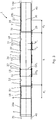
- the well tubular metal structure 100 has a first inner diameter ID W1 and a first outer diameter OD W1
- the well tubular metal structure 100 has a second outer diameter OD W2 which is smaller than the first outer diameter. If during running the well tubular metal structure in the small diameter borehole, circulation of fluid is poor due to an unexpected narrowing of the borehole, the well tubular metal structure can then be retracted, and part of a plurality of tubular sections of the well tubular metal structure can be dismounted and replaced with tubular sections having a smaller outer diameter OD W2 , as shown in Fig. 2 .
- the planner cannot foresee every incident occurring during drilling and subsequent operations, and therefore the planner often plans to have more than one diameter casing/well tubular metal structure ready for completion but some components, such as annular barriers, are more expensive than just tubular pipe/sections and by the present invention, the annular barriers can fit tubular pipe sections having different diameter and thus the annular barrier can be mounted to fit the different casings the planner plans to have ready when completing just by changing the end parts.
- the first and second end parts 6, 9 are tubular and have a maximum wall thickness T P1 which is larger than a maximum wall thickness T 2 of the expandable metal sleeve 2.
- the expandable metal sleeve is made of a material which is more pliant than the material of the first and second end parts. In order to determine if the material of the expandable metal sleeve is more pliant and thus easier to elongate than the material of the first and second end parts, the test standard ASTM D1457 can be used.
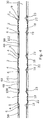
- the annular barrier 1 further comprises a split ring-shaped retaining element 17 forming a back-up for the sealing element 15.
- the split ring-shaped retaining element 17 has more than one winding, so that when the expandable tubular is expanded from the first outer diameter to the second outer diameter, the split ring-shaped retaining element partly unwinds.
- the split ring-shaped retaining element 17 may be arranged in an abutting manner to the sealing element, or an intermediate element 31 is arranged between the split ring-shaped retaining element 17 and the sealing element 15.
- the expandable metal sleeve 2 is connected to the end parts 6, 9 without any welded connections; however, in Fig. 3 the expandable metal sleeve 2 is welded to the first and second end parts 6, 9, and a connection ring 29 is arranged outside and overlapping the end 3, 4 of the expandable metal sleeve and the first end 7, 10 of the end part 6, 9 and is threadingly connected thereto.
- the well tubular metal structure 100 may have a plurality of tubular sections 40 arranged with one or more tubular sections 40 between two annular barriers 1, and the first and second end parts 6, 9 and the expandable metal sleeve 2 are mounted in succession with the plurality of tubular sections, so that the first end part 6 and the second end part 9 are arranged between the expandable metal sleeve 2 and the tubular sections along an axial extension 30 of the well tubular metal structure 100.
- the expandable metal sleeve 2, the end parts 6, 9 and the tubular sections 40 form one single walled pipe/tubular.
- an inner face 22 shown in Figs.
- a flow section 60 is furthermore arranged between two annular barriers in the first zone.
- the flow section provides primary flow into the well tubular metal structure, when the annular barriers have been expanded (as shown in Fig. 4 ), but may also be used for ejecting fluid into the annulus, e.g. for fracking the formation surrounding the well tubular metal structure 100.
- the first end part creates a first distance d 1 between the expandable metal sleeve and one of the pluralities of tubular sections
- the second end part creates a second distance d 2 between the expandable metal sleeve and another one of the plurality of tubular sections.
- the expandable metal sleeve does not overlap any of the plurality of tubular sections.
- the expandable metal sleeves are expanded by an internal fluid pressure in the well tubular metal structure.
- the entire well tubular metal structure may be pressurised from within, or an expansion tool for isolating a part of the well tubular metal structure opposite the expandable metal sleeve may be introduced in the well tubular metal structure for pressurising that part and expand the expandable metal sleeves one by one.
- the well tubular metal structure may be submerged by means of a drill pipe, and the annular barriers may be expanded by pressuring the drill pipe and the well tubular metal structure before disconnecting the drill pipe from the well tubular metal structure.
- At least one of the tubular sections between the annular barriers may comprise an inflow section for letting fluid into the well tubular metal structure also called the production casing.
- One of the tubular sections may also comprise a sensor section for measuring a condition downhole, e.g. for controlling and optimising the production.
- One of the tubular sections further up the well may also comprise a gas lift valve for introducing gas to reduce the hydrostatic pressure in the fluid column.
- the well tubular metal structure may be a production casing installed more permanently in the borehole, or the well tubular metal structure may be a velocity string used for early production. In the event that the early production shows a successful result, the velocity string is then used as the production casing.
- fluid or well fluid any kind of fluid that may be present in oil or gas wells downhole, such as natural gas, oil, oil mud, crude oil, water, etc.
- gas is meant any kind of gas composition present in a well, completion, or open hole
- oil is meant any kind of oil composition, such as crude oil, an oil-containing fluid, etc.
- Gas, oil, and water fluids may thus all comprise other elements or substances than gas, oil, and/or water, respectively.
- a well tubular metal structure or casing any kind of pipe, tubing, tubular, liner, string etc. used downhole in relation to oil or natural gas production.
- a downhole tractor can be used to push the tool all the way into position in the well.
- the downhole tractor may have projectable arms having wheels, wherein the wheels contact the inner surface of the casing for propelling the tractor and the tool forward in the casing.
- a downhole tractor is any kind of driving tool capable of pushing or pulling tools in a well downhole, such as a Well Tractor ® .
Description
- The present invention relates to an annular barrier for being mounted as part of a well tubular metal structure for providing zonal isolation in a small diameter borehole downhole for isolating a first zone from a second zone. The present invention also relates to a well tubular metal structure having a plurality of tubular sections and at least one annular barrier according to the present invention, and to a completion method of preparing an annular barrier according to the present invention.
- Annular barriers for providing a zone isolation, e.g. for isolating a hydrocarbon-containing zone from a water producing zone, is provided by arranging an isolating element, such as an expandable metal sleeve surrounding the base pipe, such as the casing or liner, and are expanded by liquid from within the base pipe. However, in small diameter wells there is no room between the inner wall of the borehole and the base pipe for such annular barrier solutions, because the inner diameter of the base pipe would be too small for an efficient production. In such small diameter wells other solutions, such as swellable material around the base pipe, are used to provide the annular barrier. Documents which are considered as disclosing the most suitable prior art are
EP 2 206 879 A1EP 2 789 792 A1 - The swelling of the swellable material is dependent on fluid content and temperature in the well and, most importantly, the deployment time from entering the well and until arrival at the determined position. Sometimes during deployment, the casing or well tubular metal structure gets stuck or is just much more difficult to deploy, resulting in the deployment time being much longer than planned, and in these cases, the swelling may occur too early and the barrier is then set too early. In small diameter wells, the space between the base pipe and the borehole wall is very narrow in order to maximise the inner diameter of the base and thus the production volume. Thus, in such small diameter wells, the risk of the casing or well tubular metal structure getting stuck is even higher than in larger wells.
- Thus, it is an object of the present invention to wholly or partly overcome the above disadvantages and drawbacks of the prior art. More specifically, it is an object to provide an improved annular barrier for small diameter wells which does not set too early, i.e. before the barrier is in the intended position in the borehole.
- The above objects, together with numerous other objects, advantages and features, which will become evident from the below description, are accomplished by a solution in accordance with the present invention by an annular barrier for being mounted as part of a well tubular metal structure for providing zonal isolation in a small diameter borehole downhole for isolating a first zone from a second zone, comprising:
- an expandable metal sleeve having a first end and a second end, and an outer face facing the borehole,
- a first end part having a first end connected to the first end of the expandable metal sleeve and a second end for being mounted as part of the well tubular metal structure, and
- a second end part having a first end connected to the second end of the expandable metal sleeve and a second end for being mounted as part of the well tubular metal structure,
- The above objects, together with numerous other objects, advantages and features, which will become evident from the below description, are accomplished by a solution in accordance with the present invention by an annular barrier for being mounted as part of a well tubular metal structure for providing zonal isolation in a small diameter borehole downhole for isolating a first zone from a second zone, the annular barrier having an inner face and comprising:
- an expandable metal sleeve having a first end and a second end, an inner face and an outer face facing the borehole,
- a first end part having a first end connected to the first end of the expandable metal sleeve and a second end for being mounted as part of the well tubular structure, the first end part having an inner face and
- a second end part having a first end connected to the second end of the expandable metal sleeve and a second end for being mounted as part of the well tubular metal structure, the second end part having an inner face,
- By the first end of the first end part being connected "end to end" to the first end of the expandable metal sleeve, and the first end of the second end part being connected "end to end" to the second end of the expandable metal sleeve, is meant that the ends are abutting and welded together or connected by a threading or similar connection. The inner face of the expandable metal sleeve thereby forms part of the inner face of the annular barrier and when mounted to the well tubular metal structure forms part of the inner face of the well tubular metal structure. Thus, the expandable metal sleeve does not overlap a tubular section of the well tubular metal structure nor the end parts in its entire thickness or length.
- By having end parts having internal or external threads, the annular barrier can be connected as part of any well tubular metal structure, and the well tubular metal structure can be made with a substantially smaller outer diameter and fit into small diameter wells than annular barriers with a base pipe and a surrounding sleeve. The expandable metal sleeve is tested for expansion up to a certain radial expansion and by having the interchangeable end parts; the tested and qualified expandable metal sleeve can fit a variety of different well tubular metal structures and can quickly be changed on the platform or rig with other end parts to fit the borehole.
- Furthermore, the first end part, the second end part and the expandable metal sleeve may form one tubular section configured to be mounted as part of the well tubular metal structure.
- Moreover, the first and second end parts and the expandable metal sleeve are mounted in succession of each other.
- In addition, the annular barrier may be without any enclosed space.
- Also, the expandable metal sleeve and the first and second end parts are connected so that the inner face of the expandable metal sleeve and the inner faces of the first and second end parts constitute the inner face of the annular barrier configured to be in contact with a production fluid conveyed by the well tubular metal structure.
- Furthermore, the expandable metal sleeve may be arranged in a non-overlapping configuration with other sections of the annular barrier.
- Also, the expandable metal sleeve may be arranged in a non-overlapping configuration with the end parts in an entire thickness and/or length of the expandable metal sleeve.
- The second end of the first end part may be provided with a female thread connection, and the second end of the second end part may be provided with a male thread connection.
- Moreover, the first and second end parts may be connected to the first and second ends of the expandable metal sleeve by means of a standard connection, such as a stub acme thread connection.
- Also, sealing elements may be arranged on the outer face of the expandable metal sleeve.
- Further, the expandable metal sleeve may have:
- a first section having a first outer diameter and a first thickness, and
- at least two circumferential projections having a thickness which is larger than a first thickness and having a second outer diameter which is larger than the first outer diameter, so that when expanding the expandable metal sleeve, the first section bulges more radially outwards than the first section, resulting in the expandable metal sleeve being strengthened.
- In addition, the expandable metal sleeve may have an outer sleeve diameter in an unexpanded state, the unexpanded outer sleeve diameter being equal to or smaller than an outer diameter of the first and second end parts.
- Additionally, the sealing elements may be arranged in grooves in the outer face of the expandable metal sleeve.
- The expandable metal sleeve may be made of a material which is more pliant than the material of the first and second end parts.
- In order to determine if the material of the expandable metal sleeve is more pliant and thus easier to elongate than the material of the first and second end parts, the test standard ASTM D1457 Elongation can be used.
- The annular barrier as described above may further comprise a split ring-shaped retaining element, the split ring-shaped retaining element forming a back-up for the sealing element.
- Furthermore, the split ring-shaped retaining element may have more than one winding, so that when the expandable tubular is expanded from the first outer diameter to the second outer diameter, the split ring-shaped retaining element partly unwinds.
- Also, the split ring-shaped retaining element may be arranged in an abutting manner to the sealing element.
- Moreover, the first and second end parts may be tubular and may have a maximum wall thickness which is larger than a maximum wall thickness of the expandable metal sleeve.
- Further, the expandable metal sleeve may be welded to the first and second end parts.
- In addition, the expandable metal sleeve may have a length, and no tubular may be arranged within the expandable metal sleeve along the entire length of the expandable metal sleeve.
- Said expandable metal sleeves may be expanded by an internal fluid pressure in the well tubular metal structure.
- At least one of the tubular sections between the expandable metal sleeves may comprise an inflow section, a sensor section or a gas lift valve.
- The present invention also relates to a well tubular metal structure having a plurality of tubular sections and at least one annular barrier according to the present invention; wherein the first and second end parts and the expandable metal sleeve are mounted in succession with the plurality of tubular sections, so that the first end part and the second end part are arranged between the expandable metal sleeve and the tubular sections along an axial extension of the well tubular metal structure.
- Also, the first part, the second end part and the expandable metal sleeve may be connected so that the inner face of the expandable metal sleeve and the inner faces of the first and second end parts constitute the inner face of the annular barrier configured to be in contact with a production fluid conveyed by the well tubular metal structure.
- Moreover, the first part, the second end part and the expandable metal sleeve may be connected so that the inner face of the expandable metal sleeve and the inner faces of the first and second end parts constitute the inner face of the well tubular metal structure configured to be in contact with a production fluid conveyed by the well tubular metal structure.
- In addition, the expandable metal sleeve is arranged in a non-overlapping configuration with any one of the tubular sections of the well tubular metal structure.
- Further, the expandable metal sleeve is arranged in a non-overlapping configuration with any element in an entire thickness and/or length of the expandable metal sleeve.
- Furthermore, the well tubular metal structure may have an inner face, and an inner face of the expandable metal sleeve may form part of the inner face of the well tubular metal structure.
- Moreover, the well tubular metal structure has an inner face, and the expandable metal sleeve and the first and second end parts may be connected so that the inner face of the expandable metal sleeve and the inner faces of the first and second end parts constitute the inner face of the annular barrier and the inner face of the well tubular metal structure.
- Also, a second annular barrier according to the present invention may be mounted as part of the well tubular metal structure, and a plurality of tubular sections may be mounted between the annular barriers.
- Moreover, the first end part may create a first distance between the expandable metal sleeve and one of the pluralities of tubular sections, and the second end part may create a second distance between the expandable metal sleeve and another one of the plurality of tubular sections.
- In addition, the expandable metal sleeve may not overlap any of the plurality of tubular sections.
- Further, the expandable metal sleeve may have an outer sleeve diameter in an unexpanded state, the unexpanded outer sleeve diameter being equal to or smaller than an outer diameter of the tubular sections forming the well tubular metal structure.
- The well tubular metal structure may be a production casing or a velocity string.
- The present invention also relates to a downhole system comprising the well tubular metal structure according to the present invention and an expansion tool for isolating a part of the well tubular metal structure opposite the expandable metal sleeve for pressurising that part in order to expand the expandable metal sleeve.
- Furthermore, the present invention relates to a completion method of preparing an annular barrier according to the present invention before being mounted as part of the well tubular metal structure, said completion method comprising:
- providing the expandable metal sleeve,
- making a female thread in the first end part,
- making a male thread in the second end part, and
- mounting the first and second end part with the expandable metal sleeve.
- Finally, the present invention relates to a completion method comprising:
- mounting an annular barrier according to the present invention as part of the well tubular metal structure,
- submerging the well tubular metal structure into the borehole,
- retracting the well tubular metal structure in the event that the well tubular metal structure cannot be submerged to a predetermined depth,
- dismounting the annular barrier and part of a plurality of tubular sections of the well tubular metal structure,
- replacing the first and second end parts with other first and second end parts having a smaller outer thread diameter,
- replacing the part of the plurality of tubular sections with other tubular sections having a smaller outer diameter,
- remounting the annular barrier having the other first and second end parts of a smaller outer thread diameter, and
- submerging the remounted well tubular metal structure.
- The invention and its many advantages will be described in more detail below with reference to the accompanying schematic drawings, which for the purpose of illustration show some non-limiting embodiments and in which:
-
Fig. 1 shows a cross-sectional view of an annular barrier for mounting as part of a well tubular metal structure in a small diameter borehole, -
Fig. 2 shows a cross-sectional view of another annular barrier for mounting as part of a well tubular metal structure in a small diameter borehole, -
Fig. 3 shows a cross-sectional view of yet another annular barrier for mounting as part of a well tubular metal structure in a small diameter borehole, and -
Fig. 4 shows a well tubular metal structure having several annular barriers for isolating production zones from other zones. - All the figures are highly schematic and not necessarily to scale, and they show only those parts which are necessary in order to elucidate the invention, other parts being omitted or merely suggested.
-
Fig. 1 shows anannular barrier 1 for being mounted as part of a welltubular metal structure 100 for providing zonal isolation in a borehole downhole for isolating afirst zone 101, e.g. producing oil or gas, from asecond zone 102, e.g. producing water, as seen inFig. 4 . Tubular sections of the well tubular metal structure are illustrated by dotted lines inFig. 1 . Theannular barrier 1 comprises anexpandable metal sleeve 2 having afirst end 3 and asecond end 4 and anouter face 5 facing the borehole. Theexpandable metal sleeve 2 is shown in its unexpanded condition, and in order to provide zonal isolation, the expandable metal sleeve is expanded to a larger outer diameter by a hydraulic pressure from within to deform the expandable metal sleeve until the outer face presses towards the wall 50 (shown inFig. 4 ) of the borehole. Theannular barrier 1 further comprises afirst end part 6 having afirst end 7 connected to the first end of the expandable metal sleeve and asecond end 8 for being mounted as part of the well tubular metal structure, and asecond end part 9 having afirst end 10 connected to the second end of the expandable metal sleeve and asecond end 11 for being mounted as part of the well tubular metal structure. Thefirst end 7 of thefirst end part 6 is connected "end to end" to thefirst end 3 of the expandable metal sleeve, so that part of thefirst end 7 overlaps part of thefirst end 3 and the ends of the parts connect end to end. Likewise, thefirst end 10 of thesecond end part 9 is connected "end to end" to thesecond end 4 of the expandable metal sleeve, so that they form one tubular pipe. Thus, there is no base pipe within the expandable metal sleeve along an entire length L (shown inFig. 3 ) of the expandable metal sleeve and the annular barrier is therefore "base-less". The second ends 8, 11 of the end parts are provided with an external thread (male thread connection) 20b or an internal thread (female thread connection) 20b for being mounted to corresponding external or internal threads of the well tubular metal structure. - By providing such base-less annular barrier, the well tubular metal structure can be made with a substantially smaller outer diameter and fit into small diameter wells than annular barriers with a base pipe and a surrounding sleeve. The expandable metal sleeve has a
first section 26 having a first outer diameter OD1 and a first thickness T1, andcircumferential projections 27 having a thickness T2 which is larger than the first thickness T1 and having a second outer diameter OD2 which is larger than the first outer diameter, so that when expanding the expandable metal sleeve, the first section bulges more radially outwards than the second section, resulting in theexpandable metal sleeve 2 being strengthened in the expanded condition. - In small diameter wells, the expandable metal sleeve does not need to expand as much as in larger diameter wells/boreholes, and therefore it is possible for the expandable metal sleeve of the "base-less" annular barrier to maintain the barrier function without the base pipe.
- Furthermore, the
circumferential projections 27 increase the strength of the expandedexpandable metal sleeve 2 when the expandable metal sleeve is not expanded more than required in small diameter wells/boreholes, so that the expandable metal sleeve can serve as both the base pipe and the barrier. The expandable metal sleeve therefore forms the well tubular metal structure. - The annular barrier has an
inner face 18 which is provided by theexpandable metal sleeve 2, thefirst end part 6 and thesecond end part 9 so that aninner face 22 of the expandable metal sleeve, aninner face 19 of thefirst end part 6 and aninner face 23 of thesecond end part 9 constitute the inner face of the annular barrier. Thus, the inner face of expandable metal sleeve thereby forms part of the inner face of the annular barrier and when mounted to the well tubular metal structure forms part of the inner face of the well tubular metal structure. Thus, the expandable metal sleeve does not overlap a tubular metal part when seen in cross-section along the longitudinal extension of the well tubular metal structure and thus does not overlap any tubular section of the well tubular metal structure nor the end parts in the entire thickness or length of the expandable metal sleeve. Therefore, the first end part, the second end part and the expandable metal sleeve form one tubular pipe configured to be mounted as one part of the well tubular metal structure between two other tubular sections of the well tubular metal structure. Thus, the expandable metal sleeve is arranged in a non-overlapping configuration with the end parts in an entire thickness and/or length of the expandable metal sleeve, and also in a non-overlapping configuration with other sections of the annular barrier. The first and second end parts and the expandable metal sleeve are mounted in succession of each other in succession with the other tubular sections mounted together to form the well tubular metal structure. - As can be seen in
Fig. 4 , theannular barrier 1 may be without any enclosed space and the expansion and setting of the annular barrier may occur without the use of ejecting pressured fluid into such annular space known from known annular barriers. Theexpandable metal sleeve 2 is expanded by pressurising the inside in the annular barrier, e.g. by plugging the well tubular metal structure further down and pressurise from the top or isolate a section of the well tubular metal structure having one or more annular barriers and pressurise just that section. The expandable metal sleeve and the first and second end parts are connected so that the inner face of the expandable metal sleeve and the inner faces of the first and second end parts constitute the inner face of the annular barrier configured to be in contact with a production fluid conveyed by the well tubular metal structure when production is initiated. - In
Fig. 1 , thesecond end 8 of thefirst end part 6 is provided with a female thread connection, i.e. aninternal thread 20b, and thesecond end 11 of thesecond end part 9 is provided with a male thread connection, i.e. anexternal thread 20a. When submerging theannular barrier 1 as part of the welltubular metal structure 100, the female thread part, i.e. thefemale thread connection 20a, is most often the thread being closest to the top. The first andsecond end parts expandable metal sleeve 2 by means of astandard connection 14, such as a stub acme thread connection as shown. The first and second ends 3, 4 of theexpandable metal sleeve 2 are provided with external threads matching internal threads of the first end part and thesecond end part 9, the internal and external threads forming the stub acme thread connections. Other standard connections within the oil industry can be used.Sealing elements 15 are arranged ingrooves 16 on the outer face of theexpandable metal sleeve 2 for increasing the sealing ability to the wall of the borehole when expanded downhole. Thegrooves 16 may be provided by thecircumferential projections 27, and when expanding the expandable metal sleeve, the first section between the projections bulges more radially outwards than the projections, forcing the sealing element radially outwards. Theexpandable metal sleeve 2 has an outer sleeve diameter Ode in an unexpanded state, the unexpanded outer sleeve diameter being equal to or sligthly smaller than an outer diameter ODP of the first and second end parts, so that the end parts protect the sealing elements while run in hole (RIH). The expandable metal sleeve ofFigs. 1 and 2 only has three grooves each having one sealing element. In another embodiment, the expandable metal sleeve has more than 3 grooves with sealing elements, e.g. 5-10 grooves. - In
Fig. 1 , the welltubular metal structure 100 has a first inner diameter IDW1 and a first outer diameter ODW1, and inFig. 2 the welltubular metal structure 100 has a second outer diameter ODW2 which is smaller than the first outer diameter. If during running the well tubular metal structure in the small diameter borehole, circulation of fluid is poor due to an unexpected narrowing of the borehole, the well tubular metal structure can then be retracted, and part of a plurality of tubular sections of the well tubular metal structure can be dismounted and replaced with tubular sections having a smaller outer diameter ODW2, as shown inFig. 2 . This can easily be performed by replacing the first andsecond end parts annular barrier 1 with other first and second end parts of a smaller outer diameter at the thread connections, and mounting other tubular sections having a smaller outer diameter. Thus, by havingdisconnectable end parts end parts - As shown in
Fig. 2 , the first andsecond end parts expandable metal sleeve 2. The expandable metal sleeve is made of a material which is more pliant than the material of the first and second end parts. In order to determine if the material of the expandable metal sleeve is more pliant and thus easier to elongate than the material of the first and second end parts, the test standard ASTM D1457 can be used. - In
Fig. 3 , theannular barrier 1 further comprises a split ring-shapedretaining element 17 forming a back-up for the sealingelement 15. The split ring-shapedretaining element 17 has more than one winding, so that when the expandable tubular is expanded from the first outer diameter to the second outer diameter, the split ring-shaped retaining element partly unwinds. Thus, the split ring-shapedretaining element 17 may be arranged in an abutting manner to the sealing element, or anintermediate element 31 is arranged between the split ring-shapedretaining element 17 and the sealingelement 15. - In
Figs. 1 and 2 , theexpandable metal sleeve 2 is connected to theend parts Fig. 3 theexpandable metal sleeve 2 is welded to the first andsecond end parts connection ring 29 is arranged outside and overlapping theend first end end part - As shown in
Fig. 4 , the welltubular metal structure 100 may have a plurality oftubular sections 40 arranged with one or moretubular sections 40 between twoannular barriers 1, and the first andsecond end parts expandable metal sleeve 2 are mounted in succession with the plurality of tubular sections, so that thefirst end part 6 and thesecond end part 9 are arranged between theexpandable metal sleeve 2 and the tubular sections along anaxial extension 30 of the welltubular metal structure 100. Theexpandable metal sleeve 2, theend parts tubular sections 40 form one single walled pipe/tubular. Thus, an inner face 22 (shown inFigs. 1-3 ) of theexpandable metal sleeve 2 forms part of the inner face 21 (shown inFigs. 1-3 ) of the well tubular metal structure. Aflow section 60 is furthermore arranged between two annular barriers in the first zone. The flow section provides primary flow into the well tubular metal structure, when the annular barriers have been expanded (as shown inFig. 4 ), but may also be used for ejecting fluid into the annulus, e.g. for fracking the formation surrounding the welltubular metal structure 100. - As shown in
Figs. 1 and 2 , the first end part creates a first distance d1 between the expandable metal sleeve and one of the pluralities of tubular sections, and the second end part creates a second distance d2 between the expandable metal sleeve and another one of the plurality of tubular sections. Thus, the expandable metal sleeve does not overlap any of the plurality of tubular sections. - The expandable metal sleeves are expanded by an internal fluid pressure in the well tubular metal structure. In order to provide an internal pressure, the entire well tubular metal structure may be pressurised from within, or an expansion tool for isolating a part of the well tubular metal structure opposite the expandable metal sleeve may be introduced in the well tubular metal structure for pressurising that part and expand the expandable metal sleeves one by one. The well tubular metal structure may be submerged by means of a drill pipe, and the annular barriers may be expanded by pressuring the drill pipe and the well tubular metal structure before disconnecting the drill pipe from the well tubular metal structure.
- Even though not shown, at least one of the tubular sections between the annular barriers may comprise an inflow section for letting fluid into the well tubular metal structure also called the production casing. One of the tubular sections may also comprise a sensor section for measuring a condition downhole, e.g. for controlling and optimising the production. One of the tubular sections further up the well may also comprise a gas lift valve for introducing gas to reduce the hydrostatic pressure in the fluid column.
- The well tubular metal structure may be a production casing installed more permanently in the borehole, or the well tubular metal structure may be a velocity string used for early production. In the event that the early production shows a successful result, the velocity string is then used as the production casing.
- By fluid or well fluid is meant any kind of fluid that may be present in oil or gas wells downhole, such as natural gas, oil, oil mud, crude oil, water, etc. By gas is meant any kind of gas composition present in a well, completion, or open hole, and by oil is meant any kind of oil composition, such as crude oil, an oil-containing fluid, etc. Gas, oil, and water fluids may thus all comprise other elements or substances than gas, oil, and/or water, respectively.
- By a well tubular metal structure or casing is meant any kind of pipe, tubing, tubular, liner, string etc. used downhole in relation to oil or natural gas production.
- In the event that the tool is not submergible all the way into the casing, a downhole tractor can be used to push the tool all the way into position in the well. The downhole tractor may have projectable arms having wheels, wherein the wheels contact the inner surface of the casing for propelling the tractor and the tool forward in the casing. A downhole tractor is any kind of driving tool capable of pushing or pulling tools in a well downhole, such as a Well Tractor®.
- Although the invention has been described in the above in connection with preferred embodiments of the invention, it will be evident for a person skilled in the art that several modifications are conceivable without departing from the invention as defined by the following claims.
wherein the second ends of the end parts are provided with male or female thread connections for being mounted to corresponding male or female thread connections of the well tubular metal structure.
wherein the second ends of the end parts are provided with male or female thread connections for being mounted to corresponding male or female thread connections of the well tubular metal structure.
Claims (15)
- An annular barrier (1) for being mounted as part of a well tubular metal structure (100) for providing zonal isolation in a small diameter borehole (50) downhole for isolating a first zone (101) from a second zone (102), the annular barrier having an inner face (18) and comprising:- an expandable metal sleeve (2) having a first end (3) and a second end (4), an inner face (22) and an outer face (5) facing the borehole,- a first end part (6) having a first end (7) connected to the first end of the expandable metal sleeve and a second end (8) for being mounted as part of the well tubular metal structure, the first end part having an inner face (19) and- a second end part (9) having a first end (10) connected to the second end of the expandable metal sleeve and a second end (11) for being mounted as part of the well tubular metal structure, the second end part having an inner face (23),wherein the first end (7) of the first end part (6) is connected end to end to the first end (3) of the expandable metal sleeve, and the first end (10) of the second end part (9) is connected end to end to the second end (4) of the expandable metal sleeve, the expandable metal sleeve and the first and second end parts being connected so that the inner face (22) of the expandable metal sleeve and the inner faces (19, 23) of the first and second end parts constitute the inner face (18) of the annular barrier, and
wherein the second ends (8, 11) of the end parts are provided with male or female thread connections for being mounted to corresponding male or female thread connections of the well tubular metal structure. - An annular barrier according to claim 1, wherein the second end (8) of the first end part is provided with a female thread connection (20a), and the second end (11) of the second end part is provided with a male thread connection (20b).
- An annular barrier according to claim 1 or 2, wherein the first and second end parts are connected to the first and second ends of the expandable metal sleeve by means of a standard connection (14), such as a stub acme thread connection.
- An annular barrier according to any of the preceding claims, wherein sealing elements (15) are arranged on the outer face of the expandable metal sleeve.
- An annular barrier according to any of the preceding claims, wherein the expandable metal sleeve has:- a first section (26) having a first outer diameter (OD1) and a first thickness (T1), and- at least two circumferential projections (27) having a thickness which is larger than a first thickness and having a second outer diameter (OD2) which is larger than the first outer diameter, so that when expanding the expandable metal sleeve, the first section bulges more radially outwards than the first section, resulting in the expandable metal sleeve being strengthened.
- An annular barrier according to any of the preceding claims, wherein the expandable metal sleeve is made of a material which is more pliant than the material of the first and second end parts.
- An annular barrier according to any of claims 4 or 5, further comprising a split ring-shaped retaining element (17), the split ring-shaped retaining element forming a back-up for the sealing element.
- An annular barrier according to any of the preceding claims, wherein the first and second end parts are tubular and have a maximum wall thickness (TP1) which is larger than a maximum wall thickness (T2) of the expandable metal sleeve.
- An annular barrier according to any of the preceding claims, wherein the expandable metal sleeve has a length (L), and no tubular is arranged within the expandable metal sleeve along the entire length of the expandable metal sleeve.
- A well tubular metal structure (100) having a plurality of tubular sections (40) and at least one annular barrier (1) according to any of the preceding claims; wherein the first and second end parts and the expandable metal sleeve are mounted in succession with the plurality of tubular sections, so that the first end part and the second end part are arranged between the expandable metal sleeve and the tubular sections along an axial extension of the well tubular metal structure.
- A well tubular metal structure according to claim 10, wherein the well tubular metal structure has an inner face (21), and the expandable metal sleeve and the first and second end parts are connected so that the inner face (22) of the expandable metal sleeve and the inner faces (19, 23) of the first and second end parts constitute the inner face (18) of the annular barrier and the inner face (21) of the well tubular metal structure.
- A well tubular metal structure according to claim 10 or 11, wherein a second annular barrier (1) according to any of claims 1-9 is mounted as part of the well tubular metal structure and a plurality of tubular sections (40) is mounted between the annular barriers.
- A well tubular metal structure according to any of claims 10-12, wherein the first end part creates a first distance (d1) between the expandable metal sleeve and one of the plurality of tubular sections, and the second end part creates a second distance (d2) between the expandable metal sleeve and another one of the plurality of tubular sections.
- A completion method of preparing an annular barrier according to any of claims 1-9 before being mounted as part of the well tubular metal structure, said completion method comprising:- providing the expandable metal sleeve,- making a female thread in the first end part,- making a male thread in the second end part, and- mounting the first and second end part with the expandable metal sleeve.
- A completion method comprising:- mounting an annular barrier according to any of claims 1-9 as part of the well tubular metal structure,- submerging the well tubular metal structure into the borehole,- retracting the well tubular metal structure in the event that the well tubular metal structure cannot be submerged to a predetermined depth,- dismounting the annular barrier and part of a plurality of tubular sections of the well tubular metal structure,- replacing the first and second end parts with other first and second end parts having a smaller outer thread diameter,- replacing the part of the plurality of tubular sections with other tubular sections having a smaller outer diameter,- remounting the annular barrier having the other first and second end parts of a smaller outer thread diameter, and- submerging the remounted well tubular metal structure.
Applications Claiming Priority (3)
| Application Number | Priority Date | Filing Date | Title |
|---|---|---|---|
| EP17183604 | 2017-07-27 | ||
| EP17200098.6A EP3480421A1 (en) | 2017-11-06 | 2017-11-06 | Annular barrier for small diameter wells |
| PCT/EP2018/070249 WO2019020729A1 (en) | 2017-07-27 | 2018-07-26 | Annular barrier for small diameter wells |
Publications (2)
| Publication Number | Publication Date |
|---|---|
| EP3658744A1 EP3658744A1 (en) | 2020-06-03 |
| EP3658744B1 true EP3658744B1 (en) | 2021-12-01 |
Family
ID=63077853
Family Applications (1)
| Application Number | Title | Priority Date | Filing Date |
|---|---|---|---|
| EP18748883.8A Active EP3658744B1 (en) | 2017-07-27 | 2018-07-26 | Annular barrier for small diameter wells |
Country Status (9)
| Country | Link |
|---|---|
| US (1) | US10731435B2 (en) |
| EP (1) | EP3658744B1 (en) |
| CN (1) | CN110892133A (en) |
| AU (1) | AU2018308919B2 (en) |
| CA (1) | CA3069881A1 (en) |
| DK (1) | DK3658744T3 (en) |
| RU (1) | RU2765939C2 (en) |
| SA (1) | SA520411019B1 (en) |
| WO (1) | WO2019020729A1 (en) |
Family Cites Families (15)
| Publication number | Priority date | Publication date | Assignee | Title |
|---|---|---|---|---|
| US3385367A (en) * | 1966-12-07 | 1968-05-28 | Kollsman Paul | Sealing device for perforated well casing |
| US4482086A (en) * | 1983-08-04 | 1984-11-13 | Uop Inc. | Expandable packer assembly for sealing a well screen to a casing |
| US4892144A (en) * | 1989-01-26 | 1990-01-09 | Davis-Lynch, Inc. | Inflatable tools |
| US7121352B2 (en) * | 1998-11-16 | 2006-10-17 | Enventure Global Technology | Isolation of subterranean zones |
| GB0417328D0 (en) * | 2004-08-04 | 2004-09-08 | Read Well Services Ltd | Apparatus and method |
| ES2464457T3 (en) * | 2009-01-12 | 2014-06-02 | Welltec A/S | Annular barrier and annular barrier system |
| US8684096B2 (en) * | 2009-04-02 | 2014-04-01 | Key Energy Services, Llc | Anchor assembly and method of installing anchors |
| RU98041U1 (en) * | 2010-05-24 | 2010-09-27 | Общество с ограниченной ответственностью "ВНИИБТ - Буровой инструмент" | PACKER HYDRAULIC PASSING WITH A SMALL VALVE ASSEMBLY |
| EP2538018A1 (en) * | 2011-06-23 | 2012-12-26 | Welltec A/S | An annular barrier with external seal |
| DK2570587T3 (en) * | 2011-09-13 | 2013-11-11 | Welltec As | Ring-shaped barrier with safety metal pipe piece |
| DK2574720T3 (en) * | 2011-09-30 | 2015-06-01 | Welltec As | Well Injection Tools |
| EP2789792A1 (en) * | 2013-04-12 | 2014-10-15 | Welltec A/S | A downhole expandable tubular |
| EP2876251A1 (en) * | 2013-11-21 | 2015-05-27 | Welltec A/S | Annular barrier with passive pressure compensation |
| EP2952672A1 (en) * | 2014-06-04 | 2015-12-09 | Welltec A/S | Downhole expandable metal tubular |
| BR112018014541B1 (en) | 2016-02-01 | 2022-12-06 | Welltec Oilfield Solutions Ag | COMPLETION SYSTEM FOR CONNECTING SEVERAL SCREENS INSIDE A TUBULAR WELL STRUCTURE, COMPLETION METHOD FOR COMPLETING THE COMPLETION SYSTEM, AND PRODUCTION METHOD FOR PRODUCING FLUID CONTAINING HYDROCARBON FROM A RESERVOIR INTO A TUBULAR WELL STRUCTURE |
-
2018
- 2018-07-26 RU RU2020106619A patent/RU2765939C2/en active
- 2018-07-26 US US16/045,805 patent/US10731435B2/en active Active
- 2018-07-26 CN CN201880046164.4A patent/CN110892133A/en active Pending
- 2018-07-26 WO PCT/EP2018/070249 patent/WO2019020729A1/en active Application Filing
- 2018-07-26 AU AU2018308919A patent/AU2018308919B2/en active Active
- 2018-07-26 DK DK18748883.8T patent/DK3658744T3/en active
- 2018-07-26 EP EP18748883.8A patent/EP3658744B1/en active Active
- 2018-07-26 CA CA3069881A patent/CA3069881A1/en not_active Abandoned
-
2020
- 2020-01-09 SA SA520411019A patent/SA520411019B1/en unknown
Also Published As
| Publication number | Publication date |
|---|---|
| RU2020106619A (en) | 2021-08-27 |
| EP3658744A1 (en) | 2020-06-03 |
| RU2020106619A3 (en) | 2021-11-26 |
| WO2019020729A1 (en) | 2019-01-31 |
| US20190032441A1 (en) | 2019-01-31 |
| AU2018308919B2 (en) | 2021-05-27 |
| CA3069881A1 (en) | 2019-01-31 |
| DK3658744T3 (en) | 2022-03-07 |
| RU2765939C2 (en) | 2022-02-07 |
| SA520411019B1 (en) | 2022-12-26 |
| AU2018308919A1 (en) | 2020-03-05 |
| BR112020000688A2 (en) | 2020-07-14 |
| US10731435B2 (en) | 2020-08-04 |
| CN110892133A (en) | 2020-03-17 |
Similar Documents
| Publication | Publication Date | Title |
|---|---|---|
| US10494910B2 (en) | Active external casing packer (ECP) for frac operations in oil and gas wells | |
| US9739106B2 (en) | Angled segmented backup ring | |
| US7967077B2 (en) | Interventionless set packer and setting method for same | |
| US7699112B2 (en) | Sidetrack option for monobore casing string | |
| EP2952672A1 (en) | Downhole expandable metal tubular | |
| EP2681404B1 (en) | Expansion cone assembly for setting a liner hanger in a wellbore casing | |
| EP2867446B1 (en) | Packer assembly having dual hydrostatic pistons for redundant interventionless setting | |
| AU2012226245A1 (en) | Expansion cone assembly for setting a liner hanger in a wellbore casing | |
| EP2867447B1 (en) | Packer assembly having sequentially operated hydrostatic pistons for interventionless setting | |
| US9109435B2 (en) | Monobore expansion system—anchored liner | |
| EP3658744B1 (en) | Annular barrier for small diameter wells | |
| US11739608B2 (en) | Downhole completion system | |
| EP3480421A1 (en) | Annular barrier for small diameter wells | |
| EP4074939A1 (en) | Annular barrier and downhole system | |
| BR112020000688B1 (en) | RING BARRIER, TUBULAR METALLIC WELL STRUCTURE AND COMPLETION METHOD FOR PREPARING AN RING BARRIER | |
| CA2852351A1 (en) | Combined casing system and method |
Legal Events
| Date | Code | Title | Description |
|---|---|---|---|
| STAA | Information on the status of an ep patent application or granted ep patent |
Free format text: STATUS: UNKNOWN |
|
| STAA | Information on the status of an ep patent application or granted ep patent |
Free format text: STATUS: THE INTERNATIONAL PUBLICATION HAS BEEN MADE |
|
| PUAI | Public reference made under article 153(3) epc to a published international application that has entered the european phase |
Free format text: ORIGINAL CODE: 0009012 |
|
| STAA | Information on the status of an ep patent application or granted ep patent |
Free format text: STATUS: REQUEST FOR EXAMINATION WAS MADE |
|
| 17P | Request for examination filed |
Effective date: 20200216 |
|
| AK | Designated contracting states |
Kind code of ref document: A1 Designated state(s): AL AT BE BG CH CY CZ DE DK EE ES FI FR GB GR HR HU IE IS IT LI LT LU LV MC MK MT NL NO PL PT RO RS SE SI SK SM TR |
|
| AX | Request for extension of the european patent |
Extension state: BA ME |
|
| DAV | Request for validation of the european patent (deleted) | ||
| DAX | Request for extension of the european patent (deleted) | ||
| GRAP | Despatch of communication of intention to grant a patent |
Free format text: ORIGINAL CODE: EPIDOSNIGR1 |
|
| STAA | Information on the status of an ep patent application or granted ep patent |
Free format text: STATUS: GRANT OF PATENT IS INTENDED |
|
| INTG | Intention to grant announced |
Effective date: 20210203 |
|
| GRAJ | Information related to disapproval of communication of intention to grant by the applicant or resumption of examination proceedings by the epo deleted |
Free format text: ORIGINAL CODE: EPIDOSDIGR1 |
|
| STAA | Information on the status of an ep patent application or granted ep patent |
Free format text: STATUS: REQUEST FOR EXAMINATION WAS MADE |
|
| GRAS | Grant fee paid |
Free format text: ORIGINAL CODE: EPIDOSNIGR3 |
|
| STAA | Information on the status of an ep patent application or granted ep patent |
Free format text: STATUS: GRANT OF PATENT IS INTENDED |
|
| GRAP | Despatch of communication of intention to grant a patent |
Free format text: ORIGINAL CODE: EPIDOSNIGR1 |
|
| INTC | Intention to grant announced (deleted) | ||
| INTG | Intention to grant announced |
Effective date: 20210706 |
|
| GRAA | (expected) grant |
Free format text: ORIGINAL CODE: 0009210 |
|
| STAA | Information on the status of an ep patent application or granted ep patent |
Free format text: STATUS: THE PATENT HAS BEEN GRANTED |
|
| AK | Designated contracting states |
Kind code of ref document: B1 Designated state(s): AL AT BE BG CH CY CZ DE DK EE ES FI FR GB GR HR HU IE IS IT LI LT LU LV MC MK MT NL NO PL PT RO RS SE SI SK SM TR |
|
| REG | Reference to a national code |
Ref country code: GB Ref legal event code: FG4D |
|
| REG | Reference to a national code |
Ref country code: AT Ref legal event code: REF Ref document number: 1451931 Country of ref document: AT Kind code of ref document: T Effective date: 20211215 Ref country code: CH Ref legal event code: EP |
|
| REG | Reference to a national code |
Ref country code: IE Ref legal event code: FG4D |
|
| REG | Reference to a national code |
Ref country code: DE Ref legal event code: R096 Ref document number: 602018027522 Country of ref document: DE |
|
| REG | Reference to a national code |
Ref country code: NO Ref legal event code: T2 Effective date: 20211201 |
|
| REG | Reference to a national code |
Ref country code: DK Ref legal event code: T3 Effective date: 20220303 |
|
| REG | Reference to a national code |
Ref country code: LT Ref legal event code: MG9D |
|
| REG | Reference to a national code |
Ref country code: NL Ref legal event code: MP Effective date: 20211201 |
|
| REG | Reference to a national code |
Ref country code: AT Ref legal event code: MK05 Ref document number: 1451931 Country of ref document: AT Kind code of ref document: T Effective date: 20211201 |
|
| PG25 | Lapsed in a contracting state [announced via postgrant information from national office to epo] |
Ref country code: RS Free format text: LAPSE BECAUSE OF FAILURE TO SUBMIT A TRANSLATION OF THE DESCRIPTION OR TO PAY THE FEE WITHIN THE PRESCRIBED TIME-LIMIT Effective date: 20211201 Ref country code: LT Free format text: LAPSE BECAUSE OF FAILURE TO SUBMIT A TRANSLATION OF THE DESCRIPTION OR TO PAY THE FEE WITHIN THE PRESCRIBED TIME-LIMIT Effective date: 20211201 Ref country code: FI Free format text: LAPSE BECAUSE OF FAILURE TO SUBMIT A TRANSLATION OF THE DESCRIPTION OR TO PAY THE FEE WITHIN THE PRESCRIBED TIME-LIMIT Effective date: 20211201 Ref country code: BG Free format text: LAPSE BECAUSE OF FAILURE TO SUBMIT A TRANSLATION OF THE DESCRIPTION OR TO PAY THE FEE WITHIN THE PRESCRIBED TIME-LIMIT Effective date: 20220301 Ref country code: AT Free format text: LAPSE BECAUSE OF FAILURE TO SUBMIT A TRANSLATION OF THE DESCRIPTION OR TO PAY THE FEE WITHIN THE PRESCRIBED TIME-LIMIT Effective date: 20211201 |
|
| PG25 | Lapsed in a contracting state [announced via postgrant information from national office to epo] |
Ref country code: SE Free format text: LAPSE BECAUSE OF FAILURE TO SUBMIT A TRANSLATION OF THE DESCRIPTION OR TO PAY THE FEE WITHIN THE PRESCRIBED TIME-LIMIT Effective date: 20211201 Ref country code: PL Free format text: LAPSE BECAUSE OF FAILURE TO SUBMIT A TRANSLATION OF THE DESCRIPTION OR TO PAY THE FEE WITHIN THE PRESCRIBED TIME-LIMIT Effective date: 20211201 Ref country code: LV Free format text: LAPSE BECAUSE OF FAILURE TO SUBMIT A TRANSLATION OF THE DESCRIPTION OR TO PAY THE FEE WITHIN THE PRESCRIBED TIME-LIMIT Effective date: 20211201 Ref country code: HR Free format text: LAPSE BECAUSE OF FAILURE TO SUBMIT A TRANSLATION OF THE DESCRIPTION OR TO PAY THE FEE WITHIN THE PRESCRIBED TIME-LIMIT Effective date: 20211201 Ref country code: GR Free format text: LAPSE BECAUSE OF FAILURE TO SUBMIT A TRANSLATION OF THE DESCRIPTION OR TO PAY THE FEE WITHIN THE PRESCRIBED TIME-LIMIT Effective date: 20220302 Ref country code: ES Free format text: LAPSE BECAUSE OF FAILURE TO SUBMIT A TRANSLATION OF THE DESCRIPTION OR TO PAY THE FEE WITHIN THE PRESCRIBED TIME-LIMIT Effective date: 20211201 |
|
| PG25 | Lapsed in a contracting state [announced via postgrant information from national office to epo] |
Ref country code: NL Free format text: LAPSE BECAUSE OF FAILURE TO SUBMIT A TRANSLATION OF THE DESCRIPTION OR TO PAY THE FEE WITHIN THE PRESCRIBED TIME-LIMIT Effective date: 20211201 |
|
| PG25 | Lapsed in a contracting state [announced via postgrant information from national office to epo] |
Ref country code: SM Free format text: LAPSE BECAUSE OF FAILURE TO SUBMIT A TRANSLATION OF THE DESCRIPTION OR TO PAY THE FEE WITHIN THE PRESCRIBED TIME-LIMIT Effective date: 20211201 Ref country code: SK Free format text: LAPSE BECAUSE OF FAILURE TO SUBMIT A TRANSLATION OF THE DESCRIPTION OR TO PAY THE FEE WITHIN THE PRESCRIBED TIME-LIMIT Effective date: 20211201 Ref country code: RO Free format text: LAPSE BECAUSE OF FAILURE TO SUBMIT A TRANSLATION OF THE DESCRIPTION OR TO PAY THE FEE WITHIN THE PRESCRIBED TIME-LIMIT Effective date: 20211201 Ref country code: PT Free format text: LAPSE BECAUSE OF FAILURE TO SUBMIT A TRANSLATION OF THE DESCRIPTION OR TO PAY THE FEE WITHIN THE PRESCRIBED TIME-LIMIT Effective date: 20220401 Ref country code: EE Free format text: LAPSE BECAUSE OF FAILURE TO SUBMIT A TRANSLATION OF THE DESCRIPTION OR TO PAY THE FEE WITHIN THE PRESCRIBED TIME-LIMIT Effective date: 20211201 Ref country code: CZ Free format text: LAPSE BECAUSE OF FAILURE TO SUBMIT A TRANSLATION OF THE DESCRIPTION OR TO PAY THE FEE WITHIN THE PRESCRIBED TIME-LIMIT Effective date: 20211201 |
|
| REG | Reference to a national code |
Ref country code: DE Ref legal event code: R097 Ref document number: 602018027522 Country of ref document: DE |
|
| PG25 | Lapsed in a contracting state [announced via postgrant information from national office to epo] |
Ref country code: IS Free format text: LAPSE BECAUSE OF FAILURE TO SUBMIT A TRANSLATION OF THE DESCRIPTION OR TO PAY THE FEE WITHIN THE PRESCRIBED TIME-LIMIT Effective date: 20220401 |
|
| PLBE | No opposition filed within time limit |
Free format text: ORIGINAL CODE: 0009261 |
|
| STAA | Information on the status of an ep patent application or granted ep patent |
Free format text: STATUS: NO OPPOSITION FILED WITHIN TIME LIMIT |
|
| PG25 | Lapsed in a contracting state [announced via postgrant information from national office to epo] |
Ref country code: AL Free format text: LAPSE BECAUSE OF FAILURE TO SUBMIT A TRANSLATION OF THE DESCRIPTION OR TO PAY THE FEE WITHIN THE PRESCRIBED TIME-LIMIT Effective date: 20211201 |
|
| 26N | No opposition filed |
Effective date: 20220902 |
|
| PG25 | Lapsed in a contracting state [announced via postgrant information from national office to epo] |
Ref country code: SI Free format text: LAPSE BECAUSE OF FAILURE TO SUBMIT A TRANSLATION OF THE DESCRIPTION OR TO PAY THE FEE WITHIN THE PRESCRIBED TIME-LIMIT Effective date: 20211201 |
|
| REG | Reference to a national code |
Ref country code: DE Ref legal event code: R119 Ref document number: 602018027522 Country of ref document: DE |
|
| PG25 | Lapsed in a contracting state [announced via postgrant information from national office to epo] |
Ref country code: MC Free format text: LAPSE BECAUSE OF FAILURE TO SUBMIT A TRANSLATION OF THE DESCRIPTION OR TO PAY THE FEE WITHIN THE PRESCRIBED TIME-LIMIT Effective date: 20211201 |
|
| REG | Reference to a national code |
Ref country code: CH Ref legal event code: PL |
|
| REG | Reference to a national code |
Ref country code: BE Ref legal event code: MM Effective date: 20220731 |
|
| PG25 | Lapsed in a contracting state [announced via postgrant information from national office to epo] |
Ref country code: LU Free format text: LAPSE BECAUSE OF NON-PAYMENT OF DUE FEES Effective date: 20220726 Ref country code: LI Free format text: LAPSE BECAUSE OF NON-PAYMENT OF DUE FEES Effective date: 20220731 Ref country code: CH Free format text: LAPSE BECAUSE OF NON-PAYMENT OF DUE FEES Effective date: 20220731 |
|
| PG25 | Lapsed in a contracting state [announced via postgrant information from national office to epo] |
Ref country code: IT Free format text: LAPSE BECAUSE OF FAILURE TO SUBMIT A TRANSLATION OF THE DESCRIPTION OR TO PAY THE FEE WITHIN THE PRESCRIBED TIME-LIMIT Effective date: 20211201 Ref country code: DE Free format text: LAPSE BECAUSE OF NON-PAYMENT OF DUE FEES Effective date: 20230201 Ref country code: BE Free format text: LAPSE BECAUSE OF NON-PAYMENT OF DUE FEES Effective date: 20220731 |
|
| P01 | Opt-out of the competence of the unified patent court (upc) registered |
Effective date: 20230523 |
|
| PG25 | Lapsed in a contracting state [announced via postgrant information from national office to epo] |
Ref country code: IE Free format text: LAPSE BECAUSE OF NON-PAYMENT OF DUE FEES Effective date: 20220726 |
|
| PGFP | Annual fee paid to national office [announced via postgrant information from national office to epo] |
Ref country code: DK Payment date: 20230620 Year of fee payment: 6 |
|
| PGFP | Annual fee paid to national office [announced via postgrant information from national office to epo] |
Ref country code: NO Payment date: 20230717 Year of fee payment: 6 Ref country code: GB Payment date: 20230717 Year of fee payment: 6 |
|
| PGFP | Annual fee paid to national office [announced via postgrant information from national office to epo] |
Ref country code: FR Payment date: 20230724 Year of fee payment: 6 |