EP3658715B1 - Angepasst gesteinsbolzen mit verbesserten installationseigenschaften - Google Patents
Angepasst gesteinsbolzen mit verbesserten installationseigenschaften Download PDFInfo
- Publication number
- EP3658715B1 EP3658715B1 EP17836080.6A EP17836080A EP3658715B1 EP 3658715 B1 EP3658715 B1 EP 3658715B1 EP 17836080 A EP17836080 A EP 17836080A EP 3658715 B1 EP3658715 B1 EP 3658715B1
- Authority
- EP
- European Patent Office
- Prior art keywords
- paddle
- formation
- rock bolt
- formations
- bolt
- Prior art date
- Legal status (The legal status is an assumption and is not a legal conclusion. Google has not performed a legal analysis and makes no representation as to the accuracy of the status listed.)
- Active
Links
Images


Classifications
-
- E—FIXED CONSTRUCTIONS
- E21—EARTH OR ROCK DRILLING; MINING
- E21D—SHAFTS; TUNNELS; GALLERIES; LARGE UNDERGROUND CHAMBERS
- E21D21/00—Anchoring-bolts for roof, floor in galleries or longwall working, or shaft-lining protection
- E21D21/0026—Anchoring-bolts for roof, floor in galleries or longwall working, or shaft-lining protection characterised by constructional features of the bolts
-
- E—FIXED CONSTRUCTIONS
- E02—HYDRAULIC ENGINEERING; FOUNDATIONS; SOIL SHIFTING
- E02D—FOUNDATIONS; EXCAVATIONS; EMBANKMENTS; UNDERGROUND OR UNDERWATER STRUCTURES
- E02D5/00—Bulkheads, piles, or other structural elements specially adapted to foundation engineering
- E02D5/74—Means for anchoring structural elements or bulkheads
- E02D5/80—Ground anchors
- E02D5/808—Ground anchors anchored by using exclusively a bonding material
-
- E—FIXED CONSTRUCTIONS
- E21—EARTH OR ROCK DRILLING; MINING
- E21D—SHAFTS; TUNNELS; GALLERIES; LARGE UNDERGROUND CHAMBERS
- E21D21/00—Anchoring-bolts for roof, floor in galleries or longwall working, or shaft-lining protection
- E21D21/0006—Anchoring-bolts for roof, floor in galleries or longwall working, or shaft-lining protection characterised by the bolt material
-
- E—FIXED CONSTRUCTIONS
- E21—EARTH OR ROCK DRILLING; MINING
- E21D—SHAFTS; TUNNELS; GALLERIES; LARGE UNDERGROUND CHAMBERS
- E21D20/00—Setting anchoring-bolts
- E21D20/02—Setting anchoring-bolts with provisions for grouting
Definitions
- the invention relates to a rock bolt which is adhered in a rock hole by a resinous or cementitious adhesive and which has improved grout mixing, grout anchoring and installation stiffness properties.
- installation stiffness or stiffness The degree to which the rock bolt, and encasing grout column, axially deflects, moves or slips relatively to the support rock, again when placed under load, is referred to as installation stiffness or stiffness.
- the annulus, i.e. the thickness, of resin between the installed rock bolt and the rock hole walls must meet tight limits as set by the manufacturer of the resin or grout. This is by virtue of the fact that a particular resin will have a specific modulus of elasticity ("modulus"). Notwithstanding the specific modulus, generally, increasing the thickness will decrease the stiffness of the installation.
- Another factor that affects stiffness is the density of the resin around the bolt, especially about the most vital part of the bolt, being a leading end portion of the bolt, the focal point of the support provided by the bolt.
- the presence of voids or bubbles reduces the density and, ultimately, reduces the stiffness.
- the integral anchor portion of the bolt is comprised of a series of paddle formations, each of which extend laterally from the cylindrical surface of the body, and each of which is radially offset relatively to adjacent formations at 90°.
- Each of these paddle formations has a longitudinal axis that is aligned to the elongate axis of the body. In this orientation, the opposed faces of each paddle formation are perpendicularly presented to the rotational direction of the rock bolt when spun.
- the present invention at least partially addresses the aforementioned problems.
- a first layer of the coating may be provided with a thickness at least about 0.1 mm and a crystallinity between about 16% and about 30%, and a second layer of the coating may be provided with a thickness at least about 0.1 mm and a crystallinity between about 6% and about 14%. Either the first layer or second layer may contact the elongate metal member.
- US 4,955,219 discloses a method of making a rock bolt with a thread on a section thereof comprising the steps of; providing a metal bar of circular or near circular crosssection having a diameter which is substantially equal to the pitch diameter of the thread to be provided thereon; passing the bar in a single pass between a pair of rolls to pinch the bar at intervals to cold form protrusions spaced from one another in staggered formation on opposite sides of the bar along a selected section thereof; displacing one or more of said rolls away from the other at a selected time to ensure that said protrusions are formed only on said selected section of bar; straightening the bar in its cold condition; and cold rolling in a thread with said pitch diameter on a further selected section of the bar which is free of the said protrusions.
- AU 2016100070 provides a grouted rock bolt which includes, an elongate body of a suitable steel material having, a first distal end and an opposed second proximal end, a threaded portion at the second end, a first end portion extending from the first end of the body which is adapted with a first plurality of integrally formed anchors, at least one integrally formed anchor on the body, between the threaded portion and the first end portion, a first stem portion between the first end portion and the at least one integrally formed anchor, wherein the first stem portion has a smooth cylindrical surface; wherein each integrally formed anchor is a flattened formation that exceeds the diameter of the body and which defines a plane; and wherein each integrally formed anchor is adapted to be harder than the stem portion.
- WO 99/61749 discloses a rock bolt and a method of forming a rock bolt.
- the bolt includes a paddle section formed by deforming a portion of the bolt through application of an eccentric shear force.
- the invention provides a grout anchored rock bolt as defined in the appended claim 1. Further option features are recited in the associated dependent claims.
- the material may be a suitable metal material.
- Each projection is a paddle formation, aligned in the longitudinal axis of the body, which extends laterally from the body in two diametrically opposed radial directions.
- the integral anchor portion comprises either three or four paddle formations radially offset in a range 55° to 65° and 40° to 50° respectively. More preferably, the integral anchor comprises four paddle formations radially offset at 45°. Alternatively, the integral anchor comprises three paddle formations radially offset at 60°
- the body may include a first and a second integral anchor portion.
- the first anchor portion may be positioned towards a first end of the body and the second anchor portion may positioned towards a second end of the body.
- a grout anchored rock bolt which includes an elongate cylindrical body of a suitable steel material which has at least one integral anchor portion which comprises of a plurality of serially arranged paddle formations, to provide opposed first and second faces and opposed first and second edges separating the faces, wherein each formation is radially offset relatively to the preceding formation at an angle that is not orthogonal and wherein the edges follow a helical pattern.
- Each paddle formation may extend laterally from the body in two diametrically opposed radial directions
- the plurality of serially arranged paddle formations may be consecutively serially arranged.
- the plurality of paddle formations are equidistantly radially offset.
- the integral anchor portion comprises either three or four paddle formations radially offset in a range 55° to 65° and 40° to 50° respectively. More preferably, the integral anchor comprises four paddle formations radially offset at 45°. Alternatively, the integral anchor comprises three paddle formations radially offset at 60°.
- the body may include a first and a second integral anchor portion.
- the first anchor portion may be positioned towards a first end of the body and the second anchor portion may positioned towards a second end of the body.
- the invention also provides a first method of manufacturing a paddle adapted rock bolt as defined in the appended claim 7.
- the invention also provides a second method of manufacturing a paddle adapted rock bolt as defined in the appended claim 8. Further optional features are recited in the associated dependent claims.
- the claimed method includes at least the steps of:
- Steps (c) to (e) may be repeated to provide a third paddle formation.
- the body is turned each time through 60°.
- steps (c) to (e) may be repeated to provide a third and a fourth paddle formation.
- the body is turned each time through 45°.
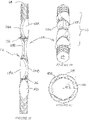
- FIGS 1A to 1C illustrate a rock bolt 10A in accordance with a first embodiment of a first aspect of the invention which, in use, is adhered in a rock hole by a resinous or cementitious adhesive.
- the rock bolt 10A has a solid cylindrical steel body 12, which extends between a first distal end 14 and an opposed end (not shown) which latter end will, in use, project from a rock hole in which the bolt is placed as will be described more fully below.
- the surface of the bolt can be profiled, as illustrated, for increased resistive interaction with the grout in use or smooth for yielding along the smooth portions.
- This single anchor portion preferably is biased towards the distal end 14.
- This portion comprises a series of end-to-end, or consecutive serial, paddle formations.
- the formations are respectively designated 18A, and 18B and 18C. It is contemplated however that the bolt can have two integral anchor portions; a first portion biased towards the distal end and a second portion biased towards the opposed end.
- Each paddle formation 18 is formed by flattening the body 12, in a suitable cold forming process, such that the body expands in opposed directions which are orthogonal to the direction of the flattening force.
- This flattening process adapts the cylindrical rock bolt body to locally exceed its diameter in two diametrically opposed radial directions, X and Y (see Figure 1B ) respectively, providing lobed extensions about a central axial line (dotted line in Figure 1B ) which are respectively designated 20A and 20B on paddle formation 18A.
- the length of each paddle formation is aligned with the longitudinal axis of the body.
- Each paddle formation has a first face and a second face, respectively designated 22A and 22B, and opposed first and second edges, respectively designated 24A (on paddle 18A) and 24B (on paddle 18B), which separate the faces.
- Each lobe 20 of each paddle formation 18 has a grout pressing surface 26 which is at a trailing end of each edge.
- the anchor portion 16 can comprise of a series of lobed formations which are not paddle formations in that they only extend laterally from the surface of the body 12 in one radial direction.
- paddle formations of the type described above are known in the art, these paddle formations are orthogonally offset from one another.
- the paddle formations 18 are not orthogonally offset.
- the formations are radially offset by 60°. This offset or phase rotation is illustrated best in Figure 1C .
- a rock bolt 10B illustrated in Figures 2A to 2C .
- This bolt has four paddle formations, respectively designated 18A to 18D, included in the integral anchor portion 16, with each of the formations phase rotated through 45° as best illustrated in Figure 2C .
- each paddle formation 18, and the grout pressing surfaces 26 that they present acts on a part of the grout that has not been acted upon by another paddle formation in the series.
- the rock bolt 10A does not achieve full grout interaction as, viewed in plan, there are columnar spaces 30 of grout that are not acted upon by any of the lobes 20 of the paddle formations 18.
- the integral anchor portion spreads the stress, imparted into the anchoring medium by the paddle formations, more evenly along the length of the portion and ensures that the zone of influence (hereinafter referred to as the "stressed zone”) from each paddle formation, when under load, does not interact with the stressed zone created by a preceding paddle formation i.e. the paddle formation does not act in the shadow of the preceding paddle formation.
- This configuration not only increases the ultimate load carrying capacity of the bolt, due to improved anchorage, but also, surprisingly, the stiffness when installed. As a result of the increased stiffness of the installation, the bolt is better able to maintain the integrity of the supported rock mass.
- the invention provides a grout or resin bolt which has improved anchoring and stiffness features when anchored in a rock hole with a resinous or cementitious adhesive.
- the rock bolt of the invention will have the same support performance as a larger diameter bolt without the unique configuration of the paddle formations in the integral anchor portion.
- a smaller diameter bolt can be used, reducing the amount of steel and therefore cost, without compromising on performance.
- FIGS 3 to 5 illustrate a rock bolt 10C in accordance with a second aspect of the invention, which, in use, is adhered in a rock hole by a resinous or cementitious adhesive.
- the rock bolt 10C has a solid cylindrical steel body 12, which extends between a first leading end 14 and an opposed end 15 (see Figure 3 ) which latter end will, in use, project from a rock hole in which the bolt is placed.
- the surface of the bolt can be profiled for increased resistive interaction with the grout in use or smooth for yielding along the smooth portions.
- the bolt 10C has a single integral anchor portion 16A disposed towards the distal end 14. This is the most important location for an anchor portion as it is along this distal end portion of the bolt that the supportive functionality of the bolt is focussed.
- This portion 16A comprises a twisted series of paddle formations which, in this example, is a set of four formations which are respectively designated 18A, 18B, 18C and 18D.
- these paddle formations intra and inter, have a twisted configuration that comes about employing one of two methods of the invention; a twisting method and a forming method. Each method will be described in turn.
- each paddle formation 18 is formed by flattening the body 12, by any suitable cold forming means, such that the body expands in opposed directions which are orthogonal to the direction of the flattening force.
- This flattening process adapts the cylindrical rock bolt body to locally exceed its diameter in two diametrically opposed radial directions.
- each formation is provided with the first and second faces (22A and 22B) and the first and second edges (24A and 24B).
- the faces 20 will present perpendicularly to the rotational direction of the spinning bolt, when spun in the resin in use, with the concomitant disadvantages described in the background.
- the paddle formations 18 not orthogonally offset, as with the bolts (10A and 10B), they also do not present front-on to passage through the resin.
- the rock bolt is twisted.
- the twisting step is illustrated in Figure 6E .
- This twisting can be achieved by gripping the bolt body 12 at two locations, for example at spaced locations designated A and B on Figure 6E , on either side of the anchor portion 16A. Torque can then be applied to the bolt at both locations, in opposite directions or at one of these locations, whilst holding the bolt at the other location to prevent spin.
- the body 12 is twisted to an extent where a lateral centre 37 (illustrated in dotted outline in Figure 5 ) of a fourth paddle formation 18D of the plurality is offset at 135° relatively to a first paddle formation 18A of the plurality, the result is that the series of four paddle formations will each be orientated at 45o relatively to adjacent formations. In this manner, a series of paddle formations with a phase rotation of 45o is achieved.
- a pair of dies 34 is used to form the cylindrical steel body 12 with paddle formations 18 that have curvilinear or twisted faces 22.
- Each die is complementarily shaped with a curved die surface 36.
- first length 38 the body 12 is pressed between the dies, either one die moving and the other stationary or both moving together as illustrated with directional arrows in Figure 7B .
- This action forms a first paddle formation 18A with twisted or curved faces 22.
- the body 12 is then shifted along and turned through 60o or 45o, depending upon whether three or four formations respectively are going to be formed, to present a second length 40 to the action of the dies. These steps are illustrated in Figures 7C and 7D . Again, the dies press a second paddle formation 18B ( Figure 7E ). Further formations are formed by repeating the steps although these subsequent steps are not illustrated for ease of illustration and explanation.
- the single integral anchor portion 16A can be formed with a plurality of the curvilinear paddle formations 18 in a single forming process.
- a multiple die tool is used that includes 3 or 4 dies that are simultaneously actuated in multiple planes on the body 12 to form the anchor portion 16A.
- each paddle formation 18 will have a twist induced in each of the faces 22 and edges 24 or a curvilinear surface pressed into the body to provide the faces 22 such that, synergistically across its length, this anchor portion 16A will function like an auger; drawing resin along the bolt, towards the top of the hole.
- the rock bolt With the top portion of the hole supplied with sufficient resin, the rock bolt is anchored along the critically important part of the bolt body i.e. the leading end portion, whilst creation of voids due is reduced due to improved resin flow across the faces.
- a first bolt (represented by the - - - - line) was configured in terms of the first aspect of the invention to have paddles prior art, having paddles radially offset by radially offset by 45°.
- a second bolt (represented by the - ⁇ - line) was configured in terms of the first aspect of the invention to have paddles radially offset by 60°.
- a third bolt (represented by the ⁇ line) was configured in terms of the prior art to have paddles radially offset by 90°.
- a fourth bolt (represented by the - line) was configured in terms of the second aspect of the invention to have twisted paddles, helically arranged, and radially offset by 45°.
- first and the second rock bolts which accord with the first aspect of the invention, exhibit significantly improved load support capacity when compared with a state of the art paddled bolt i.e. the first bolt.
- the fourth bolt exhibits improved support capacity over, not only the state of the art, but its contemporaries.
Landscapes
- Engineering & Computer Science (AREA)
- Mining & Mineral Resources (AREA)
- Structural Engineering (AREA)
- Life Sciences & Earth Sciences (AREA)
- General Life Sciences & Earth Sciences (AREA)
- Geology (AREA)
- Geochemistry & Mineralogy (AREA)
- Paleontology (AREA)
- Civil Engineering (AREA)
- General Engineering & Computer Science (AREA)
- Piles And Underground Anchors (AREA)
- Devices Affording Protection Of Roads Or Walls For Sound Insulation (AREA)
- Dowels (AREA)
- Joining Of Building Structures In Genera (AREA)
- Pit Excavations, Shoring, Fill Or Stabilisation Of Slopes (AREA)
Claims (8)
- Mit Mörtel verankerter Gesteinsbolzen (10A), der einen länglichen zylindrischen Körper (12) aus einem geeigneten Material beinhaltet, der zumindest einen einstückigen Ankerabschnitt (16) aufweist, der aus einer Vielzahl Vorsprüngen (20A,20B) umfasst, von denen sich jeder seitlich von dem Körper (12) in zumindest einer radialen Richtung erstreckt, wobei die Vorsprünge (20A,20B) aufeinanderfolgend seriell entlang der Länge des Ankerabschnittes (16) angeordnet sind, und wobei
jeder Vorsprung (20A,20B) eine Paddelformation (18A, 18B, 18C, 18D) ist, die in der Längsachse des Körpers (12) ausgerichtet ist und sich seitlich von dem Körper (12) in zwei diametral gegenüberliegende radiale Richtungen erstreckt, dadurch gekennzeichnet, dass jede Paddelformation (18A, 18B, 18C, 18D) relativ zu der vorhergehenden Formation (18A, 18B, 18C, 18D) in einem Winkel, der nicht orthogonal ist, radial versetzt ist und keine benachbarte oder nahe beabstandete Paddelformation (18A, 18B, 18C, 18D) in dem Schatten einer vorhergehenden Paddelformation (18A, 18B, 18C, 18D) ist, wenn der Gesteinsbolzen (10A) in Draufsicht betrachtet wird. - Mit Mörtel verankerter Gesteinsbolzen (10A) nach Anspruch 1, wobei der einstückige Ankerabschnitt (16) entweder drei oder vier Paddelformationen (18A, 18B, 18C, 18D) umfasst, die in einem Bereich jeweils 55° bis 65° und 40° bis 50° radial versetzt sind.
- Mit Mörtel verankerter Gesteinsbolzen (10A) nach Anspruch 2, wobei die einstückige Ankerportierung (16) vier Paddelformationen (18A, 18B, 18C, 18D) umfasst, die um 45° radial versetzt sind.
- Mit Mörtel verankerter Gesteinsbolzen (10A) nach Anspruch 2, wobei der einstückige Ankerabschnitt (16) drei Paddelformationen (18A, 18B, 18C, 18D) umfasst, die um 60° radial versetzt sind.
- Mit Mörtel verankerter Gesteinsbolzen (10A) nach einem der vorhergehenden Ansprüche, wobei der Körper (12) einen ersten und einen zweiten einstückigen Ankerabschnitt (16) beinhaltet.
- Mit Mörtel verankerter Gesteinsbolzen (10A) nach Anspruch 5, wobei der erste Ankerabschnitt (!6) zu einem ersten Ende des Körpers (12) positioniert ist und der zweite Ankerabschnitt (16) zu einem zweiten Ende des Körpers (12) positioniert ist.
- Verfahren zum Herstellen eines mit Mörtel verankerten Gesteinsbolzens (10A) mit verbesserten Mörtelinstallationseigenschaften, das die folgenden Schritte beinhaltet:(a) Bereitstellen eines länglichen zylindrischen Körpers (12) aus einem geeigneten Stahlmaterial;(b) Abflachen des Körpers (12) in Intervallen entlang einer Länge des Körpers (12), um drei oder vier Paddelformationen (18A, 18B, 18C, 18D) zu bilden, die sich alle seitlich von dem Körper (12) in einer einzelnen Ebene erstrecken; und(c) Verdrehen des Körpers (12) um seine Längsachse, um die Paddelformationen (18A, 18B, 18C, 18D) aus der einzelnen Ebene zu drehen;dadurch gekennzeichnet, dass ein Körper (12) mit drei Paddelformationen (18A, 18B, 18C) in Schritt (c) in einem Ausmaß verdreht wird, bei dem eine seitliche Mitte der dritten Paddelformation (18C) um 120° relativ zu einer ersten Paddelformation (18A) radial versetzt ist, und ein Körper mit vier Paddelformationen (18A, 18B, 18C, 18D) in Schritt (c) in einem Ausmaß verdreht wird, bei dem eine seitliche Mitte der vierten Paddelformation (18D) um 135° relativ zu einer ersten Paddelformation (18A) radial versetzt ist.
- Verfahren zum Herstellen eines paddelangepassten Gesteinsbolzens (10A) mit verbesserten Mörtelinstallationseigenschaften, das die folgenden Schritte beinhaltet:(a) Bereitstellen eines länglichen zylindrischen Körpers (12) aus einem geeigneten Stahlmaterial;(b) Bereitstellen eines Paars Matrizen (34) eines Formwerkzeugs, bei dem die Matrizen (34) komplementär mit einer verdrehten Oberfläche (36) geformt sind;(c) Pressen des Körpers (12) an einer ersten Stelle zwischen dem Paar Matrizen (34), um eine erste Paddelformation (18A) mit gegenüberliegenden Flächen bereitzustellen, jede mit einer verdrehten Oberfläche (22);(d) Drehen des Körpers (12) um seine Längsachse über einen Winkel, der nicht orthogonal ist;(e) Pressen des Körpers (12) an einer zweiten Stelle zwischen dem Paar Matrizen (34), um eine zweite Paddelformation (18B) mit gegenüberliegenden Flächen bereitzustellen, jede mit einer verdrehten Oberfläche (22); und(f) Wiederholen der Schritte (c) bis (e), um eine dritte Paddelformation (18C) bereitzustellen, wobei der Körper (12) bei jedem Schritt (d) über 60° gedreht wird, oder Wiederholen der Schritte (c) bis (e), um eine dritte Paddelformation (18C) und eine vierte Paddelformation (18D) bereitzustellen, wobei der Körper (12) bei jedem Schritt (d) über 45° gedreht wird.
Applications Claiming Priority (3)
| Application Number | Priority Date | Filing Date | Title |
|---|---|---|---|
| ZA201705076 | 2017-07-26 | ||
| ZA201705575 | 2017-08-17 | ||
| PCT/ZA2017/000010 WO2019023719A1 (en) | 2017-07-26 | 2017-09-14 | ADAPTED ANCHOR BOLT HAVING IMPROVED INSTALLATION PROPERTIES |
Publications (2)
| Publication Number | Publication Date |
|---|---|
| EP3658715A1 EP3658715A1 (de) | 2020-06-03 |
| EP3658715B1 true EP3658715B1 (de) | 2022-09-07 |
Family
ID=61094606
Family Applications (1)
| Application Number | Title | Priority Date | Filing Date |
|---|---|---|---|
| EP17836080.6A Active EP3658715B1 (de) | 2017-07-26 | 2017-09-14 | Angepasst gesteinsbolzen mit verbesserten installationseigenschaften |
Country Status (12)
| Country | Link |
|---|---|
| US (1) | US10858937B2 (de) |
| EP (1) | EP3658715B1 (de) |
| AU (1) | AU2017425150B2 (de) |
| BR (1) | BR112020001625B1 (de) |
| CA (1) | CA3070607C (de) |
| CL (1) | CL2020000211A1 (de) |
| ES (1) | ES2928206T3 (de) |
| MX (1) | MX2020000975A (de) |
| PE (1) | PE20200324A1 (de) |
| PT (1) | PT3658715T (de) |
| WO (1) | WO2019023719A1 (de) |
| ZA (1) | ZA201706245B (de) |
Family Cites Families (14)
| Publication number | Priority date | Publication date | Assignee | Title |
|---|---|---|---|---|
| US4360292A (en) * | 1980-05-28 | 1982-11-23 | Keeler Andrew L | Grouted strand anchor and method of making same |
| DE3504543C1 (de) * | 1985-02-11 | 1986-05-15 | Bochumer Eisenhütte Heintzmann GmbH & Co KG, 4630 Bochum | Klebeanker |
| US4955219A (en) * | 1986-11-14 | 1990-09-11 | Videx-Wire Products (Proprietary) Limited | Rock bolt |
| US5054146A (en) * | 1988-12-08 | 1991-10-08 | Videx-Wire Products (Pty.) Limited | Anchor bolt |
| GB2241998A (en) * | 1990-03-16 | 1991-09-18 | Newkem Australia | Rock bolt |
| AUPP367598A0 (en) * | 1998-05-22 | 1998-06-18 | Industrial Rollformers Pty Limited | Rock bolt and method of forming a rock bolt |
| US7037058B2 (en) * | 2001-03-21 | 2006-05-02 | Industrial Roll Formers Pty. Ltd. | Resin embedded rock bolt |
| US7736738B2 (en) * | 2003-12-17 | 2010-06-15 | Terrasimco Inc. | Coated mining bolt |
| US20050158127A1 (en) * | 2004-01-21 | 2005-07-21 | Fergusson Jeffrey R. | Yielding strata bolt |
| DE102007005540B4 (de) * | 2006-02-24 | 2015-04-23 | Friedr. Ischebeck Gmbh | Verfahren und Injektionsanker mit fixiertem Statikmischer |
| NO332912B1 (no) * | 2008-12-23 | 2013-01-28 | Dynamic Rock Support As | Forbedret bergbolt med plogende ankere |
| AU2013229665B2 (en) * | 2012-03-09 | 2017-04-27 | Minova International Limited | Strand, cable bolt and its installation |
| CL2014001002A1 (es) | 2013-12-12 | 2014-11-28 | Ncm Innovations Pty Ltd | Perno de anclaje en roca que incluye un cuerpo cilindrico alargado que tiene, un primer extremo distal y un segundo extremo proximal opuesto, una porcion roscada en el segundo extremo, un primer anclaje situado en o al menos parcialmente situado en una primera porcion de extremo del cuerpo, un segundo anclaje, una primera porcion de vastago entre el primer y el segundo anclaje. |
| AU2016100070A4 (en) * | 2016-01-27 | 2016-03-03 | Epiroc Drilling Tools Ab | Grout Anchored Rock Bolt |
-
2017
- 2017-09-14 CA CA3070607A patent/CA3070607C/en active Active
- 2017-09-14 US US16/634,238 patent/US10858937B2/en active Active
- 2017-09-14 AU AU2017425150A patent/AU2017425150B2/en active Active
- 2017-09-14 ZA ZA2017/06245A patent/ZA201706245B/en unknown
- 2017-09-14 PT PT178360806T patent/PT3658715T/pt unknown
- 2017-09-14 MX MX2020000975A patent/MX2020000975A/es unknown
- 2017-09-14 ES ES17836080T patent/ES2928206T3/es active Active
- 2017-09-14 BR BR112020001625-0A patent/BR112020001625B1/pt active IP Right Grant
- 2017-09-14 PE PE2020000142A patent/PE20200324A1/es unknown
- 2017-09-14 WO PCT/ZA2017/000010 patent/WO2019023719A1/en not_active Ceased
- 2017-09-14 EP EP17836080.6A patent/EP3658715B1/de active Active
-
2020
- 2020-01-24 CL CL2020000211A patent/CL2020000211A1/es unknown
Also Published As
| Publication number | Publication date |
|---|---|
| WO2019023719A8 (en) | 2020-02-13 |
| CA3070607C (en) | 2023-04-04 |
| ES2928206T3 (es) | 2022-11-16 |
| PT3658715T (pt) | 2022-10-06 |
| AU2017425150A8 (en) | 2021-03-04 |
| AU2017425150A1 (en) | 2020-02-06 |
| ZA201706245B (en) | 2020-08-26 |
| AU2017425150B2 (en) | 2021-06-24 |
| US10858937B2 (en) | 2020-12-08 |
| CA3070607A1 (en) | 2019-01-31 |
| EP3658715A1 (de) | 2020-06-03 |
| BR112020001625B1 (pt) | 2023-02-07 |
| PE20200324A1 (es) | 2020-02-13 |
| BR112020001625A2 (pt) | 2020-07-21 |
| WO2019023719A1 (en) | 2019-01-31 |
| US20200157939A1 (en) | 2020-05-21 |
| MX2020000975A (es) | 2020-07-14 |
| CL2020000211A1 (es) | 2020-06-26 |
Similar Documents
| Publication | Publication Date | Title |
|---|---|---|
| US7866116B2 (en) | Method for connecting layers of nailable material together | |
| EP4021659B1 (de) | Verfahren und vorrichtung zum formen von gewinde-verbindungen und -stangen | |
| RU2407894C1 (ru) | Деформируемая штанговая крепь | |
| US10781842B2 (en) | Expansion anchor | |
| US5735653A (en) | Anchor rod for composite anchors | |
| US7632045B2 (en) | Detachable anchor bolt mixing head for use in mine roof support systems and method of using same | |
| US11920620B2 (en) | Connecting element | |
| AU2011335895B2 (en) | A nut assembly | |
| EP3658715B1 (de) | Angepasst gesteinsbolzen mit verbesserten installationseigenschaften | |
| AU2007233555B2 (en) | A yielding rock bolt | |
| US6447228B1 (en) | Rock bolt and method of forming a rock bolt | |
| EP4182573B1 (de) | Hybridschraube mit unterteilter keilnut | |
| US10982443B1 (en) | Hybrid post-installed anchor for concrete | |
| CN106089891B (zh) | 连接锚栓以及连接锚栓系统 | |
| WO2010093330A1 (en) | Torque retention screw thread fastener and corresponding thread roll die | |
| KR20050106798A (ko) | 록볼트용 고정장치 | |
| AU2021218166A1 (en) | Rock bolt | |
| EP2146103A2 (de) | Spreizanker | |
| AU5396601A (en) | Nut break out system |
Legal Events
| Date | Code | Title | Description |
|---|---|---|---|
| STAA | Information on the status of an ep patent application or granted ep patent |
Free format text: STATUS: UNKNOWN |
|
| STAA | Information on the status of an ep patent application or granted ep patent |
Free format text: STATUS: THE INTERNATIONAL PUBLICATION HAS BEEN MADE |
|
| PUAI | Public reference made under article 153(3) epc to a published international application that has entered the european phase |
Free format text: ORIGINAL CODE: 0009012 |
|
| STAA | Information on the status of an ep patent application or granted ep patent |
Free format text: STATUS: REQUEST FOR EXAMINATION WAS MADE |
|
| 17P | Request for examination filed |
Effective date: 20200122 |
|
| AK | Designated contracting states |
Kind code of ref document: A1 Designated state(s): AL AT BE BG CH CY CZ DE DK EE ES FI FR GB GR HR HU IE IS IT LI LT LU LV MC MK MT NL NO PL PT RO RS SE SI SK SM TR |
|
| AX | Request for extension of the european patent |
Extension state: BA ME |
|
| DAV | Request for validation of the european patent (deleted) | ||
| DAX | Request for extension of the european patent (deleted) | ||
| STAA | Information on the status of an ep patent application or granted ep patent |
Free format text: STATUS: EXAMINATION IS IN PROGRESS |
|
| 17Q | First examination report despatched |
Effective date: 20211001 |
|
| GRAP | Despatch of communication of intention to grant a patent |
Free format text: ORIGINAL CODE: EPIDOSNIGR1 |
|
| STAA | Information on the status of an ep patent application or granted ep patent |
Free format text: STATUS: GRANT OF PATENT IS INTENDED |
|
| INTG | Intention to grant announced |
Effective date: 20220323 |
|
| RAP1 | Party data changed (applicant data changed or rights of an application transferred) |
Owner name: EPIROC DRILLING TOOLS AB |
|
| GRAS | Grant fee paid |
Free format text: ORIGINAL CODE: EPIDOSNIGR3 |
|
| GRAA | (expected) grant |
Free format text: ORIGINAL CODE: 0009210 |
|
| STAA | Information on the status of an ep patent application or granted ep patent |
Free format text: STATUS: THE PATENT HAS BEEN GRANTED |
|
| AK | Designated contracting states |
Kind code of ref document: B1 Designated state(s): AL AT BE BG CH CY CZ DE DK EE ES FI FR GB GR HR HU IE IS IT LI LT LU LV MC MK MT NL NO PL PT RO RS SE SI SK SM TR |
|
| REG | Reference to a national code |
Ref country code: GB Ref legal event code: FG4D |
|
| REG | Reference to a national code |
Ref country code: CH Ref legal event code: EP Ref country code: AT Ref legal event code: REF Ref document number: 1517137 Country of ref document: AT Kind code of ref document: T Effective date: 20220915 |
|
| REG | Reference to a national code |
Ref country code: DE Ref legal event code: R096 Ref document number: 602017061626 Country of ref document: DE |
|
| REG | Reference to a national code |
Ref country code: IE Ref legal event code: FG4D |
|
| REG | Reference to a national code |
Ref country code: FI Ref legal event code: FGE |
|
| REG | Reference to a national code |
Ref country code: PT Ref legal event code: SC4A Ref document number: 3658715 Country of ref document: PT Date of ref document: 20221006 Kind code of ref document: T Free format text: AVAILABILITY OF NATIONAL TRANSLATION Effective date: 20220930 |
|
| REG | Reference to a national code |
Ref country code: SE Ref legal event code: TRGR |
|
| REG | Reference to a national code |
Ref country code: ES Ref legal event code: FG2A Ref document number: 2928206 Country of ref document: ES Kind code of ref document: T3 Effective date: 20221116 |
|
| REG | Reference to a national code |
Ref country code: LT Ref legal event code: MG9D |
|
| REG | Reference to a national code |
Ref country code: NL Ref legal event code: MP Effective date: 20220907 |
|
| PG25 | Lapsed in a contracting state [announced via postgrant information from national office to epo] |
Ref country code: RS Free format text: LAPSE BECAUSE OF FAILURE TO SUBMIT A TRANSLATION OF THE DESCRIPTION OR TO PAY THE FEE WITHIN THE PRESCRIBED TIME-LIMIT Effective date: 20220907 Ref country code: NO Free format text: LAPSE BECAUSE OF FAILURE TO SUBMIT A TRANSLATION OF THE DESCRIPTION OR TO PAY THE FEE WITHIN THE PRESCRIBED TIME-LIMIT Effective date: 20221207 Ref country code: LV Free format text: LAPSE BECAUSE OF FAILURE TO SUBMIT A TRANSLATION OF THE DESCRIPTION OR TO PAY THE FEE WITHIN THE PRESCRIBED TIME-LIMIT Effective date: 20220907 Ref country code: LT Free format text: LAPSE BECAUSE OF FAILURE TO SUBMIT A TRANSLATION OF THE DESCRIPTION OR TO PAY THE FEE WITHIN THE PRESCRIBED TIME-LIMIT Effective date: 20220907 |
|
| REG | Reference to a national code |
Ref country code: AT Ref legal event code: MK05 Ref document number: 1517137 Country of ref document: AT Kind code of ref document: T Effective date: 20220907 |
|
| PG25 | Lapsed in a contracting state [announced via postgrant information from national office to epo] |
Ref country code: HR Free format text: LAPSE BECAUSE OF FAILURE TO SUBMIT A TRANSLATION OF THE DESCRIPTION OR TO PAY THE FEE WITHIN THE PRESCRIBED TIME-LIMIT Effective date: 20220907 Ref country code: GR Free format text: LAPSE BECAUSE OF FAILURE TO SUBMIT A TRANSLATION OF THE DESCRIPTION OR TO PAY THE FEE WITHIN THE PRESCRIBED TIME-LIMIT Effective date: 20221208 |
|
| REG | Reference to a national code |
Ref country code: DE Ref legal event code: R119 Ref document number: 602017061626 Country of ref document: DE |
|
| PG25 | Lapsed in a contracting state [announced via postgrant information from national office to epo] |
Ref country code: SM Free format text: LAPSE BECAUSE OF FAILURE TO SUBMIT A TRANSLATION OF THE DESCRIPTION OR TO PAY THE FEE WITHIN THE PRESCRIBED TIME-LIMIT Effective date: 20220907 Ref country code: RO Free format text: LAPSE BECAUSE OF FAILURE TO SUBMIT A TRANSLATION OF THE DESCRIPTION OR TO PAY THE FEE WITHIN THE PRESCRIBED TIME-LIMIT Effective date: 20220907 Ref country code: CZ Free format text: LAPSE BECAUSE OF FAILURE TO SUBMIT A TRANSLATION OF THE DESCRIPTION OR TO PAY THE FEE WITHIN THE PRESCRIBED TIME-LIMIT Effective date: 20220907 Ref country code: AT Free format text: LAPSE BECAUSE OF FAILURE TO SUBMIT A TRANSLATION OF THE DESCRIPTION OR TO PAY THE FEE WITHIN THE PRESCRIBED TIME-LIMIT Effective date: 20220907 |
|
| REG | Reference to a national code |
Ref country code: CH Ref legal event code: PL |
|
| REG | Reference to a national code |
Ref country code: BE Ref legal event code: MM Effective date: 20220930 |
|
| PG25 | Lapsed in a contracting state [announced via postgrant information from national office to epo] |
Ref country code: SK Free format text: LAPSE BECAUSE OF FAILURE TO SUBMIT A TRANSLATION OF THE DESCRIPTION OR TO PAY THE FEE WITHIN THE PRESCRIBED TIME-LIMIT Effective date: 20220907 Ref country code: PL Free format text: LAPSE BECAUSE OF FAILURE TO SUBMIT A TRANSLATION OF THE DESCRIPTION OR TO PAY THE FEE WITHIN THE PRESCRIBED TIME-LIMIT Effective date: 20220907 Ref country code: IS Free format text: LAPSE BECAUSE OF FAILURE TO SUBMIT A TRANSLATION OF THE DESCRIPTION OR TO PAY THE FEE WITHIN THE PRESCRIBED TIME-LIMIT Effective date: 20230107 Ref country code: EE Free format text: LAPSE BECAUSE OF FAILURE TO SUBMIT A TRANSLATION OF THE DESCRIPTION OR TO PAY THE FEE WITHIN THE PRESCRIBED TIME-LIMIT Effective date: 20220907 |
|
| PG25 | Lapsed in a contracting state [announced via postgrant information from national office to epo] |
Ref country code: NL Free format text: LAPSE BECAUSE OF FAILURE TO SUBMIT A TRANSLATION OF THE DESCRIPTION OR TO PAY THE FEE WITHIN THE PRESCRIBED TIME-LIMIT Effective date: 20220907 Ref country code: MC Free format text: LAPSE BECAUSE OF FAILURE TO SUBMIT A TRANSLATION OF THE DESCRIPTION OR TO PAY THE FEE WITHIN THE PRESCRIBED TIME-LIMIT Effective date: 20220907 Ref country code: LU Free format text: LAPSE BECAUSE OF NON-PAYMENT OF DUE FEES Effective date: 20220914 Ref country code: AL Free format text: LAPSE BECAUSE OF FAILURE TO SUBMIT A TRANSLATION OF THE DESCRIPTION OR TO PAY THE FEE WITHIN THE PRESCRIBED TIME-LIMIT Effective date: 20220907 |
|
| PLBE | No opposition filed within time limit |
Free format text: ORIGINAL CODE: 0009261 |
|
| STAA | Information on the status of an ep patent application or granted ep patent |
Free format text: STATUS: NO OPPOSITION FILED WITHIN TIME LIMIT |
|
| PG25 | Lapsed in a contracting state [announced via postgrant information from national office to epo] |
Ref country code: LI Free format text: LAPSE BECAUSE OF NON-PAYMENT OF DUE FEES Effective date: 20220930 Ref country code: DK Free format text: LAPSE BECAUSE OF FAILURE TO SUBMIT A TRANSLATION OF THE DESCRIPTION OR TO PAY THE FEE WITHIN THE PRESCRIBED TIME-LIMIT Effective date: 20220907 Ref country code: CH Free format text: LAPSE BECAUSE OF NON-PAYMENT OF DUE FEES Effective date: 20220930 Ref country code: DE Free format text: LAPSE BECAUSE OF NON-PAYMENT OF DUE FEES Effective date: 20230401 |
|
| 26N | No opposition filed |
Effective date: 20230608 |
|
| GBPC | Gb: european patent ceased through non-payment of renewal fee |
Effective date: 20221207 |
|
| PG25 | Lapsed in a contracting state [announced via postgrant information from national office to epo] |
Ref country code: SI Free format text: LAPSE BECAUSE OF FAILURE TO SUBMIT A TRANSLATION OF THE DESCRIPTION OR TO PAY THE FEE WITHIN THE PRESCRIBED TIME-LIMIT Effective date: 20220907 |
|
| PG25 | Lapsed in a contracting state [announced via postgrant information from national office to epo] |
Ref country code: BE Free format text: LAPSE BECAUSE OF NON-PAYMENT OF DUE FEES Effective date: 20220930 |
|
| PG25 | Lapsed in a contracting state [announced via postgrant information from national office to epo] |
Ref country code: GB Free format text: LAPSE BECAUSE OF NON-PAYMENT OF DUE FEES Effective date: 20221207 |
|
| PG25 | Lapsed in a contracting state [announced via postgrant information from national office to epo] |
Ref country code: FR Free format text: LAPSE BECAUSE OF NON-PAYMENT OF DUE FEES Effective date: 20221107 |
|
| PG25 | Lapsed in a contracting state [announced via postgrant information from national office to epo] |
Ref country code: CY Free format text: LAPSE BECAUSE OF FAILURE TO SUBMIT A TRANSLATION OF THE DESCRIPTION OR TO PAY THE FEE WITHIN THE PRESCRIBED TIME-LIMIT Effective date: 20220907 |
|
| PG25 | Lapsed in a contracting state [announced via postgrant information from national office to epo] |
Ref country code: MK Free format text: LAPSE BECAUSE OF FAILURE TO SUBMIT A TRANSLATION OF THE DESCRIPTION OR TO PAY THE FEE WITHIN THE PRESCRIBED TIME-LIMIT Effective date: 20220907 Ref country code: IT Free format text: LAPSE BECAUSE OF FAILURE TO SUBMIT A TRANSLATION OF THE DESCRIPTION OR TO PAY THE FEE WITHIN THE PRESCRIBED TIME-LIMIT Effective date: 20220907 Ref country code: HU Free format text: LAPSE BECAUSE OF FAILURE TO SUBMIT A TRANSLATION OF THE DESCRIPTION OR TO PAY THE FEE WITHIN THE PRESCRIBED TIME-LIMIT; INVALID AB INITIO Effective date: 20170914 |
|
| PG25 | Lapsed in a contracting state [announced via postgrant information from national office to epo] |
Ref country code: BG Free format text: LAPSE BECAUSE OF FAILURE TO SUBMIT A TRANSLATION OF THE DESCRIPTION OR TO PAY THE FEE WITHIN THE PRESCRIBED TIME-LIMIT Effective date: 20220907 |
|
| PG25 | Lapsed in a contracting state [announced via postgrant information from national office to epo] |
Ref country code: MT Free format text: LAPSE BECAUSE OF FAILURE TO SUBMIT A TRANSLATION OF THE DESCRIPTION OR TO PAY THE FEE WITHIN THE PRESCRIBED TIME-LIMIT Effective date: 20220907 |
|
| PGFP | Annual fee paid to national office [announced via postgrant information from national office to epo] |
Ref country code: PT Payment date: 20250902 Year of fee payment: 9 Ref country code: FI Payment date: 20250917 Year of fee payment: 9 |
|
| PGFP | Annual fee paid to national office [announced via postgrant information from national office to epo] |
Ref country code: SE Payment date: 20250918 Year of fee payment: 9 |
|
| PGFP | Annual fee paid to national office [announced via postgrant information from national office to epo] |
Ref country code: IE Payment date: 20250918 Year of fee payment: 9 |
|
| PG25 | Lapsed in a contracting state [announced via postgrant information from national office to epo] |
Ref country code: TR Free format text: LAPSE BECAUSE OF FAILURE TO SUBMIT A TRANSLATION OF THE DESCRIPTION OR TO PAY THE FEE WITHIN THE PRESCRIBED TIME-LIMIT Effective date: 20220907 |
|
| PGFP | Annual fee paid to national office [announced via postgrant information from national office to epo] |
Ref country code: ES Payment date: 20251010 Year of fee payment: 9 |