EP3658408B1 - Child safety seat - Google Patents
Child safety seat Download PDFInfo
- Publication number
- EP3658408B1 EP3658408B1 EP18749093.3A EP18749093A EP3658408B1 EP 3658408 B1 EP3658408 B1 EP 3658408B1 EP 18749093 A EP18749093 A EP 18749093A EP 3658408 B1 EP3658408 B1 EP 3658408B1
- Authority
- EP
- European Patent Office
- Prior art keywords
- seat
- child safety
- frame
- safety seat
- child
- Prior art date
- Legal status (The legal status is an assumption and is not a legal conclusion. Google has not performed a legal analysis and makes no representation as to the accuracy of the status listed.)
- Active
Links
Images


Classifications
-
- B—PERFORMING OPERATIONS; TRANSPORTING
- B60—VEHICLES IN GENERAL
- B60N—SEATS SPECIALLY ADAPTED FOR VEHICLES; VEHICLE PASSENGER ACCOMMODATION NOT OTHERWISE PROVIDED FOR
- B60N2/00—Seats specially adapted for vehicles; Arrangement or mounting of seats in vehicles
- B60N2/24—Seats specially adapted for vehicles; Arrangement or mounting of seats in vehicles for particular purposes or particular vehicles
- B60N2/26—Seats specially adapted for vehicles; Arrangement or mounting of seats in vehicles for particular purposes or particular vehicles for children
- B60N2/28—Seats readily mountable on, and dismountable from, existing seats or other parts of the vehicle
- B60N2/2884—Seats readily mountable on, and dismountable from, existing seats or other parts of the vehicle with protection systems against abnormal g-forces
-
- B—PERFORMING OPERATIONS; TRANSPORTING
- B60—VEHICLES IN GENERAL
- B60N—SEATS SPECIALLY ADAPTED FOR VEHICLES; VEHICLE PASSENGER ACCOMMODATION NOT OTHERWISE PROVIDED FOR
- B60N2/00—Seats specially adapted for vehicles; Arrangement or mounting of seats in vehicles
- B60N2/24—Seats specially adapted for vehicles; Arrangement or mounting of seats in vehicles for particular purposes or particular vehicles
- B60N2/26—Seats specially adapted for vehicles; Arrangement or mounting of seats in vehicles for particular purposes or particular vehicles for children
- B60N2/28—Seats readily mountable on, and dismountable from, existing seats or other parts of the vehicle
- B60N2/2821—Seats readily mountable on, and dismountable from, existing seats or other parts of the vehicle having a seat and a base part
-
- B—PERFORMING OPERATIONS; TRANSPORTING
- B60—VEHICLES IN GENERAL
- B60N—SEATS SPECIALLY ADAPTED FOR VEHICLES; VEHICLE PASSENGER ACCOMMODATION NOT OTHERWISE PROVIDED FOR
- B60N2/00—Seats specially adapted for vehicles; Arrangement or mounting of seats in vehicles
- B60N2/02—Seats specially adapted for vehicles; Arrangement or mounting of seats in vehicles the seat or part thereof being movable, e.g. adjustable
-
- B—PERFORMING OPERATIONS; TRANSPORTING
- B60—VEHICLES IN GENERAL
- B60N—SEATS SPECIALLY ADAPTED FOR VEHICLES; VEHICLE PASSENGER ACCOMMODATION NOT OTHERWISE PROVIDED FOR
- B60N2/00—Seats specially adapted for vehicles; Arrangement or mounting of seats in vehicles
- B60N2/24—Seats specially adapted for vehicles; Arrangement or mounting of seats in vehicles for particular purposes or particular vehicles
- B60N2/26—Seats specially adapted for vehicles; Arrangement or mounting of seats in vehicles for particular purposes or particular vehicles for children
- B60N2/28—Seats readily mountable on, and dismountable from, existing seats or other parts of the vehicle
- B60N2/2875—Seats readily mountable on, and dismountable from, existing seats or other parts of the vehicle inclinable, as a whole or partially
-
- B—PERFORMING OPERATIONS; TRANSPORTING
- B60—VEHICLES IN GENERAL
- B60N—SEATS SPECIALLY ADAPTED FOR VEHICLES; VEHICLE PASSENGER ACCOMMODATION NOT OTHERWISE PROVIDED FOR
- B60N2/00—Seats specially adapted for vehicles; Arrangement or mounting of seats in vehicles
- B60N2/24—Seats specially adapted for vehicles; Arrangement or mounting of seats in vehicles for particular purposes or particular vehicles
- B60N2/26—Seats specially adapted for vehicles; Arrangement or mounting of seats in vehicles for particular purposes or particular vehicles for children
- B60N2/28—Seats readily mountable on, and dismountable from, existing seats or other parts of the vehicle
- B60N2/2881—Upholstery, padded or cushioned members therefor
-
- B—PERFORMING OPERATIONS; TRANSPORTING
- B60—VEHICLES IN GENERAL
- B60N—SEATS SPECIALLY ADAPTED FOR VEHICLES; VEHICLE PASSENGER ACCOMMODATION NOT OTHERWISE PROVIDED FOR
- B60N2/00—Seats specially adapted for vehicles; Arrangement or mounting of seats in vehicles
- B60N2/24—Seats specially adapted for vehicles; Arrangement or mounting of seats in vehicles for particular purposes or particular vehicles
- B60N2/42—Seats specially adapted for vehicles; Arrangement or mounting of seats in vehicles for particular purposes or particular vehicles the seat constructed to protect the occupant from the effect of abnormal g-forces, e.g. crash or safety seats
-
- B—PERFORMING OPERATIONS; TRANSPORTING
- B60—VEHICLES IN GENERAL
- B60N—SEATS SPECIALLY ADAPTED FOR VEHICLES; VEHICLE PASSENGER ACCOMMODATION NOT OTHERWISE PROVIDED FOR
- B60N2/00—Seats specially adapted for vehicles; Arrangement or mounting of seats in vehicles
- B60N2/56—Heating or ventilating devices
-
- B—PERFORMING OPERATIONS; TRANSPORTING
- B60—VEHICLES IN GENERAL
- B60N—SEATS SPECIALLY ADAPTED FOR VEHICLES; VEHICLE PASSENGER ACCOMMODATION NOT OTHERWISE PROVIDED FOR
- B60N2/00—Seats specially adapted for vehicles; Arrangement or mounting of seats in vehicles
- B60N2/24—Seats specially adapted for vehicles; Arrangement or mounting of seats in vehicles for particular purposes or particular vehicles
- B60N2/26—Seats specially adapted for vehicles; Arrangement or mounting of seats in vehicles for particular purposes or particular vehicles for children
- B60N2/273—Seats specially adapted for vehicles; Arrangement or mounting of seats in vehicles for particular purposes or particular vehicles for children with detection or alerting means responsive to crashes
-
- B—PERFORMING OPERATIONS; TRANSPORTING
- B60—VEHICLES IN GENERAL
- B60N—SEATS SPECIALLY ADAPTED FOR VEHICLES; VEHICLE PASSENGER ACCOMMODATION NOT OTHERWISE PROVIDED FOR
- B60N2/00—Seats specially adapted for vehicles; Arrangement or mounting of seats in vehicles
- B60N2/24—Seats specially adapted for vehicles; Arrangement or mounting of seats in vehicles for particular purposes or particular vehicles
- B60N2/26—Seats specially adapted for vehicles; Arrangement or mounting of seats in vehicles for particular purposes or particular vehicles for children
- B60N2/28—Seats readily mountable on, and dismountable from, existing seats or other parts of the vehicle
-
- B—PERFORMING OPERATIONS; TRANSPORTING
- B60—VEHICLES IN GENERAL
- B60N—SEATS SPECIALLY ADAPTED FOR VEHICLES; VEHICLE PASSENGER ACCOMMODATION NOT OTHERWISE PROVIDED FOR
- B60N2/00—Seats specially adapted for vehicles; Arrangement or mounting of seats in vehicles
- B60N2/24—Seats specially adapted for vehicles; Arrangement or mounting of seats in vehicles for particular purposes or particular vehicles
- B60N2/26—Seats specially adapted for vehicles; Arrangement or mounting of seats in vehicles for particular purposes or particular vehicles for children
- B60N2/28—Seats readily mountable on, and dismountable from, existing seats or other parts of the vehicle
- B60N2/2821—Seats readily mountable on, and dismountable from, existing seats or other parts of the vehicle having a seat and a base part
- B60N2/2824—Seats readily mountable on, and dismountable from, existing seats or other parts of the vehicle having a seat and a base part part of the base being supported by the vehicle frame
-
- B—PERFORMING OPERATIONS; TRANSPORTING
- B60—VEHICLES IN GENERAL
- B60N—SEATS SPECIALLY ADAPTED FOR VEHICLES; VEHICLE PASSENGER ACCOMMODATION NOT OTHERWISE PROVIDED FOR
- B60N2/00—Seats specially adapted for vehicles; Arrangement or mounting of seats in vehicles
- B60N2/24—Seats specially adapted for vehicles; Arrangement or mounting of seats in vehicles for particular purposes or particular vehicles
- B60N2/26—Seats specially adapted for vehicles; Arrangement or mounting of seats in vehicles for particular purposes or particular vehicles for children
- B60N2/28—Seats readily mountable on, and dismountable from, existing seats or other parts of the vehicle
- B60N2/2857—Seats readily mountable on, and dismountable from, existing seats or other parts of the vehicle characterised by the peculiar orientation of the child
- B60N2/286—Seats readily mountable on, and dismountable from, existing seats or other parts of the vehicle characterised by the peculiar orientation of the child forward facing
-
- B—PERFORMING OPERATIONS; TRANSPORTING
- B60—VEHICLES IN GENERAL
- B60N—SEATS SPECIALLY ADAPTED FOR VEHICLES; VEHICLE PASSENGER ACCOMMODATION NOT OTHERWISE PROVIDED FOR
- B60N2/00—Seats specially adapted for vehicles; Arrangement or mounting of seats in vehicles
- B60N2/24—Seats specially adapted for vehicles; Arrangement or mounting of seats in vehicles for particular purposes or particular vehicles
- B60N2/26—Seats specially adapted for vehicles; Arrangement or mounting of seats in vehicles for particular purposes or particular vehicles for children
- B60N2/28—Seats readily mountable on, and dismountable from, existing seats or other parts of the vehicle
- B60N2/2857—Seats readily mountable on, and dismountable from, existing seats or other parts of the vehicle characterised by the peculiar orientation of the child
- B60N2/2863—Seats readily mountable on, and dismountable from, existing seats or other parts of the vehicle characterised by the peculiar orientation of the child backward facing
-
- B—PERFORMING OPERATIONS; TRANSPORTING
- B60—VEHICLES IN GENERAL
- B60N—SEATS SPECIALLY ADAPTED FOR VEHICLES; VEHICLE PASSENGER ACCOMMODATION NOT OTHERWISE PROVIDED FOR
- B60N2205/00—General mechanical or structural details
- B60N2205/30—Seat or seat parts characterised by comprising plural parts or pieces
Definitions
- This invention relates generally to a child safety seat. More specifically, although not exclusively, this invention relates to a child safety seat for a vehicle.
- child safety seats must pass stringent safety tests before they are certified for sale.
- the head of a crash test dummy located therein must not move beyond a distance of 700 mm from the seat upon which the rear-facing child safety seat is secured.
- the crash test dummy must not be subjected to greater than 55G chest deceleration.
- DE4405147A1 discloses a child seat for small children in vehicle.
- the seat shell opening faces opposite the direction of travel and the tubular seat frame is fixed on the main seat by a safety belt built into the vehicle.
- the belt runs at right angles to the seat shell and is retained on the side sections of the tubular frame so as to slide in guides.
- the belt passes under the seat shell.
- a blocking unit is provided for blocking a movement of the seat shell into a lower plane.
- US2004232747A1 discloses a child seat including a child car seat body, a back portion rotatably held in inclination by the child car seat body, a seat portion rotatably connected to a lower part of the back portion and a shock absorbing mechanism arranged between the child car seat body and either one or both of the back portion and the seat portion.
- Child safety seats suitable for older children should be relatively larger than child safety seats suitable for younger children. Moreover, children older than 2 years old typically have a greater mass than do children under the age of 15 months. Accordingly, during a vehicular accident, the forces applied to child safety seats are typically relatively greater when occupied by an older (and hence heavier) child. The displacement of prior art child safety seats is hence relatively increased during vehicular accidents when occupied by relatively older children.
- Child safety seats for babies should be appropriately inclined to the seating area of the vehicle such that the baby is not too upright. Seats which are too upright may negatively impact on the breathing of the baby. Furthermore, seats which are too upright are uncomfortable for children which may lead to non-compliance with use of the seat and/or an unhappy child.
- child safety seats are typically expensive and therefore purchasing one or more replacement child safety seats as a child grows (and hence outgrows one or more child safety seats) is costly.
- a first aspect of the invention provides a child safety seat for a vehicle, the child safety seat comprising a seat body and a frame which is removably secured or securable onto an existing vehicle seat in a rearward configuration, the frame comprising an upstanding portion and a base portion, the seat body comprising a back portion and a seat portion, the frame being pivotably attached to the back portion of the seat body such that, in use, the seat body is arranged to pivot about the pivotable attachment to the frame during a vehicular accident, the child safety seat further comprising an energy absorbing means or device located, in use, between the seat portion of the seat body and the base portion of the frame.
- the invention thus provides a child safety seat which is capable of seating a child aged up to 4 years old whilst also satisfying the above-described EU safety tests.
- the child safety seat may be sized appropriately to seat a child up to the age of 4 years old whilst ensuring that the head of a child occupant of the child safety seat does not move beyond 700 mm from a vehicle seat upon which the child safety seat is secured and/or the child occupant is not exposed to chest decelerations exceeding 55G during a vehicular accident.
- the back portion may have a proximal edge at which the back portion is attached to the seat portion and a distal or terminal edge.
- the frame may be pivotably attached, in use, to the back portion at a location between the proximal edge and the distal edge.
- the frame may be pivotably attached to the back portion at a location towards the distal edge, for example in the upper half of the back portion.
- the frame may be pivotably attached to the back portion at a location proximate or adjacent the terminal edge.
- the frame may be pivotably attached to the seat body at a location above, in use, the centre of gravity of the seat body and a child occupant thereof.
- the frame may be pivotably attached to the seat body by a hinge.
- the hinge may comprise a recess in the frame or seat body, for example and a projection on the other of the frame and seat body, ( e.g. where the projection may be configured to pivotably engage the recess).
- the child safety seat comprises an energy absorbing means or device located between the seat portion of the seat body and the base portion of the frame.
- the energy absorbing means or device may be configured to collapse or deform in a controlled manner when the child safety seat is secured onto an existing seat of a vehicle and the vehicle is involved in an accident.
- the energy absorbing means or device may comprise a device or material which is configured to collapse or deform in a controlled manner when subjected to impact loads in excess of a predetermined value.
- the seat body may be attached to the frame by or through the energy absorbing means or device.
- the energy absorbing means or device may comprise an energy absorbing structure, for example a collapsible structure.
- the energy absorbing means or device may comprise cells defined by plural walls.
- the energy absorbing means or device may comprise a honeycomb structure, for example which may comprise a metal ( e.g. aluminium or steel or the like) or polymeric material.
- the energy absorbing means or device may comprise a piston or other telescopic body.
- the frame may comprise securement means or securement(s) for securing the frame to the seat of the vehicle and/or the vehicle.
- the securement means or securement(s) may comprise a leg, for example configured or configurable to bear, in use, against a surface of the vehicle beneath and/or in front of the vehicle seat upon which the child safety seat is positioned.
- the leg may comprise an energy absorbing means or device.
- the leg may comprise a hollow elongate member.
- the energy absorbing means or device may be located or locatable within the leg, e.g. within the hollow elongate member.
- the leg may comprise a foot, for example configured to engage, in use, a surface ( e.g.
- the leg may comprise a length altering means or mechanism, for example for increasing and/or decreasing the length of the leg.
- the leg may comprise a biasing means or biaser, e.g. configured to bias the leg toward a relatively longer condition.
- the securement means or securement(s) may comprise a securement member, e.g. configured to engage a slot of the vehicle seat and/or of a rigid structure secured to the vehicle seat.
- the child safety seat may be secured or securable to the rigid structure (where provided).
- the securement member may comprise part of an ISOFIX mechanism.
- the frame comprises an upstanding portion and a base portion.
- the base portion may extend, in use, along the vehicle seat.
- the upstanding portion may comprise at least a portion of the hinge attachment for the seat.
- the said at least portion of the hinge attachment may be located at or adjacent the terminal edge of the back portion of the frame.
- the child safety seat may comprise size altering means or mechanism, for example configured or configurable to modify the child safety seat from a first condition in which the child safety seat is suitable for use by a baby less than 1 year old to a second condition in which the child safety seat is suitable for use by, say, a child which is 2, 3 or 4 years old.
- the size altering means or mechanism may comprise one or more expandable bodies, for example operable, in use, to alter the shape of the seat body.
- the seat body may have a seating area/surface for seating a child, in use.
- The, one, some or each expandable body may be expandable and/or contractible, in use, to alter the size of the seating area. Expansion in this context may comprise inflation. Contraction in this context may comprise deflation.
- The, one, some or each of the one or more expandable bodies may be expandable and/or contractible, in use, to alter the width of the seating area.
- The, one, some or each of the one or more expandable bodies may be expandable and/or contractible, in use, to alter the length of the seating area.
- The, one, some or each of the one or more expandable bodies may be expandable and/or contractible, in use, to alter the profile of the seating area.
- the expandable bodies may be arranged to actuate in the event of the detection of a vehicular accident.
- the size altering means or mechanism may comprise an angle altering means or mechanism, for example operable to alter the angle by which the seat portion of the seat body extends relative to the frame.
- the angle altering means or mechanism may comprise a displacement device (e.g. a linear or angular displacement device), for example configured or configurable to displace the seat body (e.g. the seat portion of the seat body) relative to the frame, in use.
- the displacement device may be configured or configurable to alter the angle of the seat body (e.g. the seat portion of the seat body) relative to the frame.
- the displacement device may be configured or configurable or operated or operable to alter the distance between a terminal edge of the seat portion of the seat body and the frame, e.g. of a base portion of the frame.
- the displacement device may be automatically or manually operated or operable.
- the displacement device may comprise a retractable or collapsible and/or extendable or expandable member.
- the displacement device may comprise a thread or screw and/or a nut.
- Retraction or collapse and/or extension or expansion of the retractable or collapsible and/or extendable or expandable member may be driven, e.g. by a driving means (for example a powered driving means).
- the driving means may comprise a motor.
- the seat body may be formed from a polymer.
- the seat body may comprise a unitary structure, for example the seat portion and the back portion may be integrally formed.
- the seat body may comprise a clam-shell construction.
- the seat body may be formed by injection moulding, or by any other suitable method of manufacture.
- the frame may be formed, at least partially, from metal, for example aluminium, steel, or the like.
- the frame may be formed by pressing or moulding or by any other suitable method of manufacture.
- the child safety seat may comprise a control unit, for example configured or configurable to control the size altering means or mechanism (where provided).
- the control unit may be operably to control expansion and/or contraction of the, one, some or each expandable body.
- the control unit may be programmed or programmable to control the size altering means or mechanism.
- the child safety seat may comprise an expansion means or mechanism, for example an inflation means or mechanism.
- the expansion means or mechanism may be operably connected to the, one, some or each expandable body.
- the expansion means or mechanism may be operable to expand and/or collapse the, one, some or each expandable body.
- the expansion means or mechanism may comprise a pump, for example which may be an air pump.
- the expansion means or mechanism may be electrically driven or drivable and/or manually driven or drivable.
- the child safety seat may comprise a heating system, for example one or more heating elements.
- the heating system may be located or locatable in or on the seat body.
- the seat body may be upholstered and/or may comprise a safety harness.
- the child safety seat e.g. the control unit, where provided, and/or the expansion means or mechanism, where provided, and/or the angle altering means or mechanism, where provided, and/or the heating system, where provided
- the connection may comprise a plug for connection to a vehicle's source of electricity, for example cigarette lighter plug or the like.
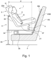
- FIG. 1 there is shown a child safety seat 1 according to a first embodiment of the invention installed on a vehicle seat VS and occupied by a child C.
- the child safety seat 1 is shown in Figure 1 in a first 'normal' condition, which is a nominal condition of the child safety seat 1 being mounted in a vehicle in a rearward configuration and prior to being subject to a vehicular accident.
- the child safety seat 1 comprises a seat body 2, a frame 3 and an energy absorbing device 4.
- the seat body 2 comprises a back portion 20, a seat portion 21 and a pair of opposed side portions 22a, 22b, which together provide a recess in which the child C is seated.
- the seat body 2 typically comprises a seat shell.
- the seat body 2 is typically upholstered with cushioning material such as foam or sponge material and a cover layer (not shown).
- the back portion 20 of the seat body 2 comprises a hinge 5 having a first hinge portion 5a, which is disposed in an upper portion 20a of the back portion 20 and spaced from a terminal edge 20b thereof.
- the side portions 22a, 22b extend from the terminal edge 20b of the back portion 20 to a terminal edge 21a of the seat portion 21.
- the frame 3 comprises a leg 30 and a support portion 31.
- the leg 30 comprises an elongate support member 32 having a first, connection, end 32a and a second, support, end 32b.
- the first, connection, end 32a is configured to attach to the support portion 32 (as will be described further below).
- the second, support, end 32b comprises a foot 33 for engaging, in use, a floor F of the vehicle in front of the seat VS upon which the child safety seat 1 is secured.
- the foot 33 is adjustable relative to the support member 32, by way of threaded attachment thereto, such that the length of the leg 30 can be adjusted.
- the support portion 31 comprises a base plate 34 having a first major surface 34a and a second, obverse, major surface 34b.
- Side walls 34c extend from opposed edges of the base plate 34, such that the side walls 34c are parallel and opposed to one another.
- the side walls 34c include a top edge which is shaped to accommodate/receive the seat portion 21 and back portion 20 of the seat body 2.
- the side walls 34c comprise a second hinge portion 5b adjacent their terminal edge.
- An abutment 35 is provided on the base plate 34, projecting from its second major surface 34b.
- a socket 36 extends from the second major surface 34b of the base plate 34, adjacent a first end thereof 34d.
- a securement member 37 extends from the base plate 34, from a second end 34e thereof, which is opposite to the first end 34d.
- the first hinge portion 5a comprises a projection 50 from the obverse surface of the back portion 20 to the surface which is occupied by a child, in use.
- the projection 50 comprises an axial passageway 51 extending therethrough.
- the second hinge portion 5b comprises a recess 52 defined between a pair of support ends 53, which extend from distal portions of the side walls 34c. Aligned apertures 54 are provided through the support ends 53.
- the recess 52 is configured to receive the projection 50 such that the axial passageway 51 is aligned with each of the apertures 54.
- a pin (not shown) is secured through the aligned projection 50 and recess 52 such that a hinge 5 is formed.
- the seat body 2 is thus hingedly attached to the frame 3.
- the energy absorbing device 4 comprises an energy absorbing structure that, in the event of an accident, absorbs energy.
- the energy absorbing structure is made from a honeycomb-like material which is able to absorb compressive impacts.
- One suitable material is manufactured by Cell bond Composites Ltd of Huntingdon UK called Hyload (RTM), others are sold as Pressload (RTM) or Hyimpact (RTM).
- the energy absorbing structure may be formed from other materials such as foams or other polymeric materials. In embodiments we prefer materials which plastically deform in the event of a vehicular impact.
- the energy absorbing device 4 may also be, for example, a piston which telescopically collapses when impacted or other device that can use the energy to do work.
- the seat body 2 Prior to installation of the child safety seat 1 at a site of use the seat body 2 is hingedly attached to the frame 3 by forming the hinge 5 (as described above).
- the energy absorbing device 4 is disposed between the base plate 34 of the frame 3 and the seat portion 21 of the seat body 2.
- the leg 30 is attached to the support portion 31 by engaging the first, connection, end 32a of the support member 32 into the socket 36 of the support portion 31.
- the socket 36 may be at the connection end 32 and the frame may include an protrusion to engage the socket 36.
- the leg 30 is configured to be removably attached to the support portion 31, for example by push fit or screw fit. However, in embodiments the leg 30 and support portion 31 may be permanently secured together.
- the frame 3 is configured to engage with, and be secured to, a rigid body RB previously secured to the vehicle seat VS.
- This rigid body RB may be the Multimac available from Multimac of Birmingham, United Kingdom, B6 4NF and as described in European patent 0844938 and which is shown in Figure 9 . In embodiments, however, other rigid bodies RB may be used.
- the frame 3 is secured to the rigid body RB on the vehicle seat VS prior to use.
- the securement member 37 at the second end 34e of the base plate 34 is engaged within a slot in the rigid body RB.
- the second major surface 34b of the base plate 34 is supported by the rigid body RB such that the abutment 35 is abutted by a projection from the rigid body RB. In this way the frame is restricted from moving away from the seat back VSB of the vehicle seat VS.
- the base plate 34 is substantially parallel to the floor F of the vehicle in front of the vehicle seat VS. If needs be, the length of the leg 30 is then adjusted, by relatively rotating the support member 32 and the foot 33, to ensure that the foot 33 engages with the floor F in front of the vehicle seat VS.
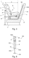
- FIG. 3 there is shown the child safety seat 1 shown in Figure 1 in a second condition, which is a collapsed condition subsequent to the child safety seat 1 experiencing a vehicular accident.
- the seat body 2 has partially rotated relative to the frame 3 and the vehicle seat VS (as indicated by arrow B), such that a terminal edge of the seat portion 21 is relatively nearer to the base plate 34 of the frame 3 than it was in the first, nominal, condition.
- the energy absorbing structure of the energy absorbing device 4 has partially collapsed in this second condition.
- the energy absorbing device 4 mitigates the quantity of energy transmitted to the child C occupying the child safety seat 1 during a vehicular accident causing the child safety seat 1 to move from the first condition to the second condition. Collapse of the energy absorbing device 4 consumes some of the energy generated in the vehicular accident, thereby reducing the amount of energy transmitted to the child C.
- the distance d' between the back of the child's head H and the seat back VSB of the vehicle seat VS onto which the child safety seat 1 is secured is less than 700 mm.
- a vehicular accident causes the back portion of prior art rear-facing child safety seats to oscillate toward and away from the seat back of the vehicle seat upon which they are secured. During this oscillation the back of the head of a child occupant of a child safety seat moves relatively toward and away from the vehicle seat upon which the child safety seat is secured.
- the distance d between the back of the head H of a dummy child occupant C of a child safety seat 1 according to the invention and the seat back VSB of the vehicle seat VS upon which the child safety seat 1 is secured does not exceed 700 mm during vehicular accidents, even when the child safety seat 1 is of sufficient dimensions to seat a dummy child of 3 years old, for example 4 years old.
- child safety seats 1 relatively reduce the distance by which the back of the head H of a child occupant C thereof moves during a vehicular accident, relative to prior art child safety seats. Therefore, the distance d remains less than 700 mm even during a vehicular accident.
- Securing the back portion 20 of the seat body 2 relative to the vehicle seat VS, by way of the frame 3, ensures that the distance by which the head H of a child occupant C of the child safety seat 1 translates during vehicular accident is relatively reduced.
- Providing an attachment location between the back portion 20 of the seat body 2 and the frame 3 provides a restriction against lateral movement of the seat body 2 away from the seat back VSB of the vehicle seat VS upon which the child safety seat 1 is secured.
- provision of a hinge 5 attaching the back portion 20 of the seat body 2 to the frame 3 provides a pivot point about which the seat body 2 may, at least partially, rotate relative to the frame 3 during a vehicular accident.
- the seat body 2 is therefore not entirely restricted from motion relative to the vehicle seat VS upon which it is secured, and, hence, the energy of impact during a vehicular accident is at least partially dissipated rather than being entirely transmitted to a child occupant C of the child safety seat 1.
- the hinge 5 has been found to be particularly beneficial to provide the hinge 5 at a position which is above, in use, the centre of gravity of the seat body 2 and a child occupant C thereof.
- the hinge is located such that only a minor portion of the back portion 20 extends beyond the hinge 5.
- that part of the back portion 20 configured to support the head H of a child occupant C moves by a relatively reduced distance away from the vehicle seat VS upon which the child safety seat 1 is secured, compared to the part of back portions of prior art child safety seats configured to support children's heads H, when subjected to a comparable external force ( e.g. during a vehicular accident).
- Prior art child safety seats may secure the seat body to the vehicle seat VS at the seat portion of the seat body. Accordingly, when the seat body is subjected to a vehicular accident the seat body pivots relative to the vehicle seat VS about the join between the back portion and seat portion of the seat body. Accordingly, the radius of rotation of the seat body of such prior art child safety seats is equal to the distance by which the back portion extends from the seat portion. With child safety seats 1 according to the invention the radius of rotation of the seat body is relatively reduced and is equal to that part of the back portion 20 extending beyond the hinge 5.
- the terminal edge of the back portion 20 according to the invention translates by a relatively reduced lateral distance from the seat back VSB of the vehicle seat VS upon which the child safety seat 1 is secured than does the terminal edge of the back portion of a prior art child safety seat.
- the back portions 20 of child safety seats 1 according to the invention rotate by a relatively reduced angle of rotation for a given applied force than do the back portions of prior art child safety seats.
- lateral displacement of the back portion 20 (and hence the head H of a child occupant C thereof) relative to the seat back VSB of the vehicle seat VS is relatively reduced.
- provision of the hinge 5 for attaching the frame 3 to the seat body 2 allows the seat body 2 to move ( e.g. partially rotate relative to the frame 3) during a vehicular accident.
- the proportion of energy from the vehicular accident transmitted to an occupant of the child safety seat 1 is therefore relatively reduced.
- Some energy is expended in moving ( e.g. rotating) the seat body 2 relative to the frame 3.
- a further proportion of the energy of the vehicular accident is expended in crushing the energy absorbing device 4.
- the energy and hence forces applied to a child occupant C of the child safety seat 1 are therefore relatively reduced. Chest decelerations induced in the child occupant C of the child safety seat 1 are thereby relatively reduced. It has been found that child safety seats 1 according to the invention therefore generate chest decelerations less than the above-described 55 g limit.
- a child safety seat 1 according to the invention may therefore be dimensioned to seat a child up to 3 or 4 years of age whilst complying with the test standards described above. Accordingly, parents may continue seating their children in child safety seats 1 according to the invention until they are relatively older than is possible with prior art child safety seats. Beneficially, the children are therefore better protected if a vehicular accident occurs.
- FIG. 4 there is shown a child safety seat 11 according to a further embodiment of the invention in which like features to those of the child safety seat 1 shown in Figure 1 are denoted by like references preceded by a '1' which will not be described herein further.
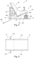
- the child safety seat 11 shown in Figure 4 differs from that shown in Figure 1 in that the child safety seat 11 comprises size adjustment means or mechanisms comprising an angle adjustment mechanism 16, a width adjustment mechanism 17 and seat body profile adjustment mechanism 18.
- the angle adjustment mechanism 16 is configured to adjust, e.g. relatively increase and/or decrease, the angle of the seat body 12 relative to the frame 13, for example the angle by which the seat portion 121 of the seat body 12 extends relative to the base plate 134 of the frame 13. Actuation of the angle adjustment mechanism 16 causes the seat body 12 to pivot about the hinge 15. Accordingly, the angle adjustment mechanism 16 functions in concert with the hinge 15 in order to adjust the angle of the seat body 12 relative to the frame 13.
- the angle adjustment mechanism 16 comprises an engagement member 160 and a fixed member 161.
- the engagement member 16 is arranged to engage with the seat portion 121 of the seat body 12 whilst the fixed member 161 is attached or attachable to the base plate 134 of the frame 13.
- the engagement member 160 is adjustable relative to the fixed member 161 such that the angle between the seat portion 121 of the seat body 12 and the base plate 134 of the frame 13 may be altered.
- the engagement member 160 comprises a bolt 160, whilst the fixed member 161 comprises a nut 161.
- the free end of the bolt 160 is arranged to engage the seat portion 121 of the seat body 12.
- the nut 161 is rotatable by electrically powered driving means (not shown) which is connectable to a source of electricity via a lead.
- the angle adjustment mechanism 16 may be manually adjustable. Electrical power is provided or providable through a cable having an electrical connection 162, which is a cigarette lighter plug 162 in this embodiment.
- the angle adjustment mechanism 16 is located or locatable on (or integrated with) the energy absorbing device 14. Therefore, in the event of a vehicular accident, the energy absorbing device 14 still at least partially crumples, thereby absorbing some of the impact energy of the accident.
- the angle adjustment mechanism 16 may be located at or adjacent the terminal edge of the seat portion 121.
- the force required to adjust the angle of the seat body 12 relative to the frame 13 is relatively reduced.
- adjustment of the angle of the seat body 12 relative to the frame 13 may be more precisely and smoothly controlled.
- the angle adjustment mechanism 16 may be programmed and/or controlled to repeatedly adjust the angle of the seat body 12 relative to the frame 13. The angle adjustment mechanism 16 may therefore be used to gently rock a child occupant C of the child safety seat 11 backwards and forwards, for example to encourage that child C to fall asleep or to otherwise calm the child C.
- the angle adjustment mechanism 16 allows the seat body 12 to be moved into a relatively more or less inclined position relative to the frame 13. As will be appreciated by one skilled in the art, babies require a relatively more inclined seat body (relative to horizontal) than do older children. Accordingly, the angle adjustment mechanism 16 allows the child safety seat 11 to be used by children across a range of ages up to 4 years old.
- the width adjustment mechanism 17 comprises one or more side expandable members 170 disposed at or adjacent the opposed sides of the seat body 12, and on the inside surface thereof.
- the width adjustment mechanism 17 is arranged to be operable to alter the width of the seating space within the seat body 12.
- Each of the side expandable members 170 is fluidly connected to a source of expansion fluid 171.
- the source of expansion fluid 171 is an air pump 171 which is manually powered.
- the air pump 171 may be electrically driven and/or may provide a further expansion fluid in addition to or alternatively to air.
- the child safety seat 11 may be adjusted to fit children of different sizes and/or ages. Accordingly, the child safety seat 11 may therefore be used for a range of ages and/or sizes of children.
- the seat body profile adjustment mechanism 18 comprises plural lateral expandable members 180 disposed on and/or across the central or seating surface of the seat body 12. In embodiments, only one lateral expandable member 180 may be provided.
- the lateral expandable members 180 are fluidly connected to an electrically driven air pump 181 for expanding or contracting said members.
- the air pump 181 is electrically connected to a controller 182 which is programmed or programmable to relatively expand or contract one or more of the plural lateral expandable members 180, to thereby alter the profile of the seating space within the seat body 12.
- the air pump 181 may be manually operated and/or may provide a further expansion fluid in addition to or alternatively to air.
- the controller 182 may be programmed or programmable through a control panel 183 (as shown in Figure 6 ).
- the controller 182 may be programmed or programmable to repeatedly expand and contract one or more of the lateral expandable members 180, for example to provide a massaging effect against a child occupant C of the child safety seat 11.
- a child occupant C of the child safety seat 11 may therefore be more readily encourage to fall asleep or to be otherwise calmed or placated.
- expansion and/or contraction of one or more of the lateral expansion members 180 toward the terminal edges of the seat portion 121 and/or the back portion 120 of the seat body 12 may be used to alter the size of the seating area of the seat body 12. Accordingly, expansion and/or contraction of one or more of the lateral expansion members 180 beneficially allows the size of the seating area of the seat body 12 to be tailored to the size of the child C seated therein (or to be seated therein).
- the size adjustment means or mechanisms allow the child safety seat 11 to be used by a range of ages and/or sizes of children. Therefore, the child safety seat 11 does not need to be replaced with sequentially larger child safety seats 11 as a child ages/grows (as is typically the practice with prior art child safety seats). Nor does the child safety seat 11 need to be replaced with a differently sized seat when a differently sized child is transported in the vehicle. This adjustability therefore provides a cost saving relative to the requirement of purchasing plural child safety seats 11 to accommodate differently sized children. It is also more convenient to not have to remove and install child safety seats 11 multiple times.
- the side expandable members 170 and/or lateral expandable members 180 may be arranged to actuate upon detection of a collision to securely embrace the occupant. If the side expandable members 170 and/or lateral expandable members 180 are formed of fluid they will provide further cushioning to the occupant.
- FIG. 7 there is shown a frame 23 for a child safety seat according to a further embodiment of the invention, wherein features similar to the frame 3 shown in Figures 1 , 2 and 3 are denoted by like references preceded by a '2' and will not be described herein further.
- the frame 23 shown in Figure 7 differs from that shown in Figures 1 , 2 and 3 in that the securement member 237 extending from the second end 234e of the base plate 234 comprises the male portion 237 of an ISOFIX (RTM) mechanism (otherwise known as a UCSS mechanism or LATCH in the USA, or UAS, Canfix in Canada).
- ISOFIX ISOFIX
- the male portion 237 of the ISOFIX mechanism is secured into the vehicle's ISOFIX slots, which comprise the female portion of the ISOFIX mechanism.
- the frame 23 may thereby be secured directly to a vehicle seat VS, absent the rigid body RB described above.
- the ISOFIX mechanism may be used in conjunction with the rigid body RB described above.
- FIG. 8 there is shown a leg 330 for a child safety seat according to a further embodiment of the invention, wherein features similar to the leg 30 shown in Figures 1 , 2 and 3 are denoted by like references preceded by a '3' and will not be described herein further.
- the leg 330 shown in Figure 8 differs from that shown in Figures 1 , 2 and 3 in that the leg 330 comprises an alternative height adjustment mechanism.
- the support member 332 is at least partially hollow, thereby defining an internal bore B along part or all of its length.
- the bore B has a first end B1 spaced from the second, support end 332b of the support member 332 and a second end B2 at the second, support end 332b of the support member 332.
- the foot 333 is attached to a piston 339 by a connection rod 339a.
- the piston 339 is shaped and sized to slidably engage with the inner surfaces of the bore B, such that the piston 339 is movable along the bore B.
- a biaser S which is a compression spring S in this embodiment, is disposed within the bore B at the first end B1 thereof.
- the piston 339 is disposed between the second end B2 of the bore B and the compression spring S.
- the bore B is filled with valving in this embodiment, which may comprise a liquid and/or a gas.
- the compression spring S is arranged to bias the piston 339 away from the first end 332a of the support member 332.
- the piston 339 Prior to installation in a vehicle the piston 339 is at least partially pushed toward the first end 332a of the support member 332, such that the foot 334 is moved adjacent the second end 332b of the support member 332.
- the foot 334 is retained in this position, either manually by the installer or by a catch or clip (not shown).
- the leg 330 is then attached to the support portion 331 and the frame 33 is secured to a vehicle seat VS, as described above.
- the spring S drives the piston 339 away from the first end 332a of the support member 332 and, hence, the foot 334 away from the second end 332b of the support member. In this way the length of the leg 330 is automatically adjusted until the foot 334 engages with the floor F in front of the vehicle seat VS upon which the child safety seat is secured.
- the biaser S acts as a secondary energy absorbing device during a vehicular accident, thereby further protecting a child occupant C of the child safety seat from experiencing excessive forces.
- the frame may comprise the first hinge portion and the seat body may comprise the second hinge portion.
- the first and second hinge portions may take any suitable shape and configuration such that a hinge connection is provided or provideable between the seat body and the frame.
- the lateral expandable members and the side expandable members may be fluidly connected to the same pump, for example which may be manually or electrically operated.
- any of the above-described embodiments may comprise a heating system, for example comprising one or more heating elements. The one or more heating elements may be located or locatable in or on the seat body.
Landscapes
- Engineering & Computer Science (AREA)
- Aviation & Aerospace Engineering (AREA)
- Transportation (AREA)
- Mechanical Engineering (AREA)
- Health & Medical Sciences (AREA)
- Child & Adolescent Psychology (AREA)
- General Health & Medical Sciences (AREA)
- Seats For Vehicles (AREA)
Description
- This invention relates generally to a child safety seat. More specifically, although not exclusively, this invention relates to a child safety seat for a vehicle.
- In many jurisdictions it is a legal requirement for children under a certain height and/or weight to be seated in rear-facing child safety seat when in a moving automobile. For example, in the UK children up to the age of 15 months old or weighing 11 kg (whichever occurs first) must be seated in rear-facing child safety seats.
- Furthermore, in many jurisdictions, child safety seats must pass stringent safety tests before they are certified for sale. For example, in the EU, during testing of a rear-facing child safety seat not supported by the dashboard, the head of a crash test dummy located therein must not move beyond a distance of 700 mm from the seat upon which the rear-facing child safety seat is secured. Moreover, the crash test dummy must not be subjected to greater than 55G chest deceleration.
- It has been found that prior art rear-facing child safety seats are often unsuited to seat children beyond the age of 18 months old and/or fail the above-described EU safety testing. This is because prior art child safety seats are too small to seat children beyond the age of 18 months old or, in the alternative, the child safety seats move during impact testing such that the head of the crash test dummy is beyond the 700 mm limit.
-
DE4405147A1 discloses a child seat for small children in vehicle. The seat shell opening faces opposite the direction of travel and the tubular seat frame is fixed on the main seat by a safety belt built into the vehicle. The belt runs at right angles to the seat shell and is retained on the side sections of the tubular frame so as to slide in guides. For attachment of the seat frame, the belt passes under the seat shell. A blocking unit is provided for blocking a movement of the seat shell into a lower plane. -
US2004232747A1 discloses a child seat including a child car seat body, a back portion rotatably held in inclination by the child car seat body, a seat portion rotatably connected to a lower part of the back portion and a shock absorbing mechanism arranged between the child car seat body and either one or both of the back portion and the seat portion. - Child safety seats suitable for older children should be relatively larger than child safety seats suitable for younger children. Moreover, children older than 2 years old typically have a greater mass than do children under the age of 15 months. Accordingly, during a vehicular accident, the forces applied to child safety seats are typically relatively greater when occupied by an older (and hence heavier) child. The displacement of prior art child safety seats is hence relatively increased during vehicular accidents when occupied by relatively older children.
- Meanwhile, in the event of a vehicular accident, a proportion of the energy of the accident is transmitted to the occupant of the child safety seat. However, the proportion transmitted to the occupant of the child safety seat must not generate chest decelerations exceeding 55G, otherwise the child safety seat will fail the above-described EU tests.
- Moreover, child safety seats for babies should be appropriately inclined to the seating area of the vehicle such that the baby is not too upright. Seats which are too upright may negatively impact on the breathing of the baby. Furthermore, seats which are too upright are uncomfortable for children which may lead to non-compliance with use of the seat and/or an unhappy child.
- Furthermore, child safety seats are typically expensive and therefore purchasing one or more replacement child safety seats as a child grows (and hence outgrows one or more child safety seats) is costly.
- It is therefore a first non-exclusive object of the invention to provide a child safety seat which mitigates one or more of the above identified problems. It is a further non-exclusive object of the invention to provide a child safety seat suitable for children up to the age of 18 months or weighing up to 13 kg (whichever occurs first) which will pass the above-described safety test requirements. It is a further non-exclusive object of the invention to provide a child safety seat suitable for older children and preferably one which will pass the above-described safety test requirements.
- Accordingly, a first aspect of the invention provides a child safety seat for a vehicle, the child safety seat comprising a seat body and a frame which is removably secured or securable onto an existing vehicle seat in a rearward configuration, the frame comprising an upstanding portion and a base portion, the seat body comprising a back portion and a seat portion, the frame being pivotably attached to the back portion of the seat body such that, in use, the seat body is arranged to pivot about the pivotable attachment to the frame during a vehicular accident, the child safety seat further comprising an energy absorbing means or device located, in use, between the seat portion of the seat body and the base portion of the frame.
- The invention thus provides a child safety seat which is capable of seating a child aged up to 4 years old whilst also satisfying the above-described EU safety tests. The child safety seat may be sized appropriately to seat a child up to the age of 4 years old whilst ensuring that the head of a child occupant of the child safety seat does not move beyond 700 mm from a vehicle seat upon which the child safety seat is secured and/or the child occupant is not exposed to chest decelerations exceeding 55G during a vehicular accident.
- The back portion may have a proximal edge at which the back portion is attached to the seat portion and a distal or terminal edge. The frame may be pivotably attached, in use, to the back portion at a location between the proximal edge and the distal edge. The frame may be pivotably attached to the back portion at a location towards the distal edge, for example in the upper half of the back portion. The frame may be pivotably attached to the back portion at a location proximate or adjacent the terminal edge. The frame may be pivotably attached to the seat body at a location above, in use, the centre of gravity of the seat body and a child occupant thereof.
- The frame may be pivotably attached to the seat body by a hinge. The hinge may comprise a recess in the frame or seat body, for example and a projection on the other of the frame and seat body, (e.g. where the projection may be configured to pivotably engage the recess).
- The child safety seat comprises an energy absorbing means or device located between the seat portion of the seat body and the base portion of the frame. The energy absorbing means or device may be configured to collapse or deform in a controlled manner when the child safety seat is secured onto an existing seat of a vehicle and the vehicle is involved in an accident. The energy absorbing means or device may comprise a device or material which is configured to collapse or deform in a controlled manner when subjected to impact loads in excess of a predetermined value.
- The seat body may be attached to the frame by or through the energy absorbing means or device. The energy absorbing means or device may comprise an energy absorbing structure, for example a collapsible structure. The energy absorbing means or device may comprise cells defined by plural walls. The energy absorbing means or device may comprise a honeycomb structure, for example which may comprise a metal (e.g. aluminium or steel or the like) or polymeric material. Alternatively the energy absorbing means or device may comprise a piston or other telescopic body.
- The frame may comprise securement means or securement(s) for securing the frame to the seat of the vehicle and/or the vehicle. The securement means or securement(s) may comprise a leg, for example configured or configurable to bear, in use, against a surface of the vehicle beneath and/or in front of the vehicle seat upon which the child safety seat is positioned. The leg may comprise an energy absorbing means or device. The leg may comprise a hollow elongate member. The energy absorbing means or device may be located or locatable within the leg, e.g. within the hollow elongate member. The leg may comprise a foot, for example configured to engage, in use, a surface (e.g. a floor) of the vehicle in front of and/or beneath the vehicle seat upon which the child safety seat is secured. The leg may comprise a length altering means or mechanism, for example for increasing and/or decreasing the length of the leg. The leg may comprise a biasing means or biaser, e.g. configured to bias the leg toward a relatively longer condition.
- The securement means or securement(s) may comprise a securement member, e.g. configured to engage a slot of the vehicle seat and/or of a rigid structure secured to the vehicle seat. The child safety seat may be secured or securable to the rigid structure (where provided). The securement member may comprise part of an ISOFIX mechanism.
- The frame comprises an upstanding portion and a base portion. The base portion may extend, in use, along the vehicle seat. The upstanding portion may comprise at least a portion of the hinge attachment for the seat. The said at least portion of the hinge attachment may be located at or adjacent the terminal edge of the back portion of the frame.
- The child safety seat may comprise size altering means or mechanism, for example configured or configurable to modify the child safety seat from a first condition in which the child safety seat is suitable for use by a baby less than 1 year old to a second condition in which the child safety seat is suitable for use by, say, a child which is 2, 3 or 4 years old.
- The size altering means or mechanism may comprise one or more expandable bodies, for example operable, in use, to alter the shape of the seat body.
- The seat body may have a seating area/surface for seating a child, in use. The, one, some or each expandable body may be expandable and/or contractible, in use, to alter the size of the seating area. Expansion in this context may comprise inflation. Contraction in this context may comprise deflation. The, one, some or each of the one or more expandable bodies may be expandable and/or contractible, in use, to alter the width of the seating area. The, one, some or each of the one or more expandable bodies may be expandable and/or contractible, in use, to alter the length of the seating area. The, one, some or each of the one or more expandable bodies may be expandable and/or contractible, in use, to alter the profile of the seating area.
- The expandable bodies may be arranged to actuate in the event of the detection of a vehicular accident.
- The size altering means or mechanism may comprise an angle altering means or mechanism, for example operable to alter the angle by which the seat portion of the seat body extends relative to the frame. The angle altering means or mechanism may comprise a displacement device (e.g. a linear or angular displacement device), for example configured or configurable to displace the seat body (e.g. the seat portion of the seat body) relative to the frame, in use. The displacement device may be configured or configurable to alter the angle of the seat body (e.g. the seat portion of the seat body) relative to the frame. The displacement device may be configured or configurable or operated or operable to alter the distance between a terminal edge of the seat portion of the seat body and the frame, e.g. of a base portion of the frame. The displacement device may be automatically or manually operated or operable. The displacement device may comprise a retractable or collapsible and/or extendable or expandable member. The displacement device may comprise a thread or screw and/or a nut. Retraction or collapse and/or extension or expansion of the retractable or collapsible and/or extendable or expandable member may be driven, e.g. by a driving means (for example a powered driving means). The driving means may comprise a motor.
- The seat body may be formed from a polymer. The seat body may comprise a unitary structure, for example the seat portion and the back portion may be integrally formed. The seat body may comprise a clam-shell construction. The seat body may be formed by injection moulding, or by any other suitable method of manufacture.
- The frame may be formed, at least partially, from metal, for example aluminium, steel, or the like. The frame may be formed by pressing or moulding or by any other suitable method of manufacture.
- The child safety seat may comprise a control unit, for example configured or configurable to control the size altering means or mechanism (where provided). The control unit may be operably to control expansion and/or contraction of the, one, some or each expandable body. The control unit may be programmed or programmable to control the size altering means or mechanism.
- The child safety seat may comprise an expansion means or mechanism, for example an inflation means or mechanism. The expansion means or mechanism may be operably connected to the, one, some or each expandable body. The expansion means or mechanism may be operable to expand and/or collapse the, one, some or each expandable body. The expansion means or mechanism may comprise a pump, for example which may be an air pump. The expansion means or mechanism may be electrically driven or drivable and/or manually driven or drivable.
- The child safety seat may comprise a heating system, for example one or more heating elements. The heating system may be located or locatable in or on the seat body. The seat body may be upholstered and/or may comprise a safety harness.
- The child safety seat (e.g. the control unit, where provided, and/or the expansion means or mechanism, where provided, and/or the angle altering means or mechanism, where provided, and/or the heating system, where provided) may be connected or connectable to a source of electricity. The connection may comprise a plug for connection to a vehicle's source of electricity, for example cigarette lighter plug or the like.
- For the avoidance of doubt, any of the features described herein apply equally to any aspect of the invention.
- Within the scope of this application it is expressly envisaged that the various aspects, embodiments, examples and alternatives set out in the preceding paragraphs, in the claims and/or in the following description and drawings, and in particular the individual features thereof, may be taken independently or in any combination. Features described in connection with one aspect or embodiment of the invention are applicable to all aspects or embodiments, unless such features are incompatible.
- Embodiments of the invention will now be described by way of example only with reference to the accompanying drawings in which:
-
Figure 1 is a sectional side view of a child safety seat according to a first embodiment of the invention installed on a vehicle seat and occupied by a child, where the child safety seat is shown in a first condition; -
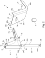
Figure 2 is an exploded perspective view of the components of the child safety seat shown inFigure 1 ; -
Figure 3 is a sectional side view of the child safety seat shown inFigure 1 shown in a second condition; -
Figure 4 is a partial sectional side view of a child safety seat according to a further embodiment of the invention; -
Figure 5 is a plan view of the child safety seat shown inFigure 4 ; -
Figure 6 is a perspective view of the frame of the child safety seat shown inFigure 4 ; -
Figure 7 is a perspective view of a frame according to a further embodiment of the invention; -
Figure 8 is a sectional side view of a leg according to a further embodiment of the invention; and -
Figure 9 is a perspective view of a prior art multiple occupancy child seat. - Referring now to
Figure 1 , there is shown a child safety seat 1 according to a first embodiment of the invention installed on a vehicle seat VS and occupied by a child C. The child safety seat 1 is shown inFigure 1 in a first 'normal' condition, which is a nominal condition of the child safety seat 1 being mounted in a vehicle in a rearward configuration and prior to being subject to a vehicular accident. - Referring also to
Figure 2 , the child safety seat 1 comprises aseat body 2, aframe 3 and anenergy absorbing device 4. - The
seat body 2 comprises aback portion 20, aseat portion 21 and a pair ofopposed side portions seat body 2 typically comprises a seat shell. Theseat body 2 is typically upholstered with cushioning material such as foam or sponge material and a cover layer (not shown). Theback portion 20 of theseat body 2 comprises ahinge 5 having afirst hinge portion 5a, which is disposed in anupper portion 20a of theback portion 20 and spaced from aterminal edge 20b thereof. Theside portions terminal edge 20b of theback portion 20 to a terminal edge 21a of theseat portion 21. - The
frame 3 comprises aleg 30 and asupport portion 31. - The
leg 30 comprises anelongate support member 32 having a first, connection,end 32a and a second, support,end 32b. The first, connection,end 32a is configured to attach to the support portion 32 (as will be described further below). The second, support,end 32b comprises afoot 33 for engaging, in use, a floor F of the vehicle in front of the seat VS upon which the child safety seat 1 is secured. Thefoot 33 is adjustable relative to thesupport member 32, by way of threaded attachment thereto, such that the length of theleg 30 can be adjusted. - The
support portion 31 comprises abase plate 34 having a firstmajor surface 34a and a second, obverse,major surface 34b.Side walls 34c extend from opposed edges of thebase plate 34, such that theside walls 34c are parallel and opposed to one another. Theside walls 34c include a top edge which is shaped to accommodate/receive theseat portion 21 and backportion 20 of theseat body 2. Theside walls 34c comprise asecond hinge portion 5b adjacent their terminal edge. - An
abutment 35 is provided on thebase plate 34, projecting from its secondmajor surface 34b. Asocket 36 extends from the secondmajor surface 34b of thebase plate 34, adjacent afirst end thereof 34d. Asecurement member 37 extends from thebase plate 34, from asecond end 34e thereof, which is opposite to thefirst end 34d. - The
first hinge portion 5a comprises aprojection 50 from the obverse surface of theback portion 20 to the surface which is occupied by a child, in use. Theprojection 50 comprises anaxial passageway 51 extending therethrough. - The
second hinge portion 5b comprises arecess 52 defined between a pair of support ends 53, which extend from distal portions of theside walls 34c.Aligned apertures 54 are provided through the support ends 53. Therecess 52 is configured to receive theprojection 50 such that theaxial passageway 51 is aligned with each of theapertures 54. Prior to use, a pin (not shown) is secured through the alignedprojection 50 andrecess 52 such that ahinge 5 is formed. Theseat body 2 is thus hingedly attached to theframe 3. - The
energy absorbing device 4 comprises an energy absorbing structure that, in the event of an accident, absorbs energy. In this embodiment the energy absorbing structure is made from a honeycomb-like material which is able to absorb compressive impacts. One suitable material is manufactured by Cell bond Composites Ltd of Huntingdon UK called Hyload (RTM), others are sold as Pressload (RTM) or Hyimpact (RTM). Additionally or alternatively, in embodiments, the energy absorbing structure may be formed from other materials such as foams or other polymeric materials. In embodiments we prefer materials which plastically deform in the event of a vehicular impact. Theenergy absorbing device 4 may also be, for example, a piston which telescopically collapses when impacted or other device that can use the energy to do work. - Prior to installation of the child safety seat 1 at a site of use the
seat body 2 is hingedly attached to theframe 3 by forming the hinge 5 (as described above). Theenergy absorbing device 4 is disposed between thebase plate 34 of theframe 3 and theseat portion 21 of theseat body 2. Theleg 30 is attached to thesupport portion 31 by engaging the first, connection,end 32a of thesupport member 32 into thesocket 36 of thesupport portion 31. Alternatively, thesocket 36 may be at theconnection end 32 and the frame may include an protrusion to engage thesocket 36. In embodiments, theleg 30 is configured to be removably attached to thesupport portion 31, for example by push fit or screw fit. However, in embodiments theleg 30 andsupport portion 31 may be permanently secured together. - In this embodiment, the
frame 3 is configured to engage with, and be secured to, a rigid body RB previously secured to the vehicle seat VS. This rigid body RB may be the Multimac available from Multimac of Birmingham, United Kingdom, B6 4NF and as described inEuropean patent 0844938 and which is shown inFigure 9 . In embodiments, however, other rigid bodies RB may be used. - The
frame 3 is secured to the rigid body RB on the vehicle seat VS prior to use. Thesecurement member 37 at thesecond end 34e of thebase plate 34 is engaged within a slot in the rigid body RB. The secondmajor surface 34b of thebase plate 34 is supported by the rigid body RB such that theabutment 35 is abutted by a projection from the rigid body RB. In this way the frame is restricted from moving away from the seat back VSB of the vehicle seat VS. In this secured arrangement thebase plate 34 is substantially parallel to the floor F of the vehicle in front of the vehicle seat VS. If needs be, the length of theleg 30 is then adjusted, by relatively rotating thesupport member 32 and thefoot 33, to ensure that thefoot 33 engages with the floor F in front of the vehicle seat VS. - In the first condition (as shown in
Figure 1 ), when a child C is seated in the child safety seat 1, the back of the child's head H is spaced from the seat back VSB of the vehicle seat VS upon which the child safety seat 1 is secured by a distance d which is less than 700 mm. - Referring now to
Figure 3 , there is shown the child safety seat 1 shown inFigure 1 in a second condition, which is a collapsed condition subsequent to the child safety seat 1 experiencing a vehicular accident. In this second condition theseat body 2 has partially rotated relative to theframe 3 and the vehicle seat VS (as indicated by arrow B), such that a terminal edge of theseat portion 21 is relatively nearer to thebase plate 34 of theframe 3 than it was in the first, nominal, condition. The energy absorbing structure of theenergy absorbing device 4 has partially collapsed in this second condition. Advantageously, theenergy absorbing device 4 mitigates the quantity of energy transmitted to the child C occupying the child safety seat 1 during a vehicular accident causing the child safety seat 1 to move from the first condition to the second condition. Collapse of theenergy absorbing device 4 consumes some of the energy generated in the vehicular accident, thereby reducing the amount of energy transmitted to the child C. - In the second condition the distance d' between the back of the child's head H and the seat back VSB of the vehicle seat VS onto which the child safety seat 1 is secured is less than 700 mm.
- As will be appreciated, a vehicular accident causes the back portion of prior art rear-facing child safety seats to oscillate toward and away from the seat back of the vehicle seat upon which they are secured. During this oscillation the back of the head of a child occupant of a child safety seat moves relatively toward and away from the vehicle seat upon which the child safety seat is secured.
- In tests, it has been surprisingly found that the distance d between the back of the head H of a dummy child occupant C of a child safety seat 1 according to the invention and the seat back VSB of the vehicle seat VS upon which the child safety seat 1 is secured does not exceed 700 mm during vehicular accidents, even when the child safety seat 1 is of sufficient dimensions to seat a dummy child of 3 years old, for example 4 years old.
- Advantageously, child safety seats 1 according to the invention relatively reduce the distance by which the back of the head H of a child occupant C thereof moves during a vehicular accident, relative to prior art child safety seats. Therefore, the distance d remains less than 700 mm even during a vehicular accident.
- Securing the
back portion 20 of theseat body 2 relative to the vehicle seat VS, by way of theframe 3, ensures that the distance by which the head H of a child occupant C of the child safety seat 1 translates during vehicular accident is relatively reduced. Providing an attachment location between theback portion 20 of theseat body 2 and theframe 3 provides a restriction against lateral movement of theseat body 2 away from the seat back VSB of the vehicle seat VS upon which the child safety seat 1 is secured. Furthermore, provision of ahinge 5 attaching theback portion 20 of theseat body 2 to theframe 3 provides a pivot point about which theseat body 2 may, at least partially, rotate relative to theframe 3 during a vehicular accident. Importantly, theseat body 2 is therefore not entirely restricted from motion relative to the vehicle seat VS upon which it is secured, and, hence, the energy of impact during a vehicular accident is at least partially dissipated rather than being entirely transmitted to a child occupant C of the child safety seat 1. - It has been found to be particularly beneficial to provide the
hinge 5 at a position which is above, in use, the centre of gravity of theseat body 2 and a child occupant C thereof. For example, the hinge is located such that only a minor portion of theback portion 20 extends beyond thehinge 5. Beneficially, that part of theback portion 20 configured to support the head H of a child occupant C moves by a relatively reduced distance away from the vehicle seat VS upon which the child safety seat 1 is secured, compared to the part of back portions of prior art child safety seats configured to support children's heads H, when subjected to a comparable external force (e.g. during a vehicular accident). - Without wishing to be bound by any particular theory, it is believed that positioning the pivot point provided by the
hinge 5 above, in use, the centre of gravity G of theseat body 2 and a child occupant C thereof a moment generated on theseat body 2 above thehinge 5 will be relatively reduced (for a given applied force). Consequently, theseat body 2 according to the invention will rotate relative to the vehicle seat VS upon which the child safety seat 1 is secured by a relatively reduced angle of rotation than will a prior art child safety seat, for a given applied force. - Prior art child safety seats may secure the seat body to the vehicle seat VS at the seat portion of the seat body. Accordingly, when the seat body is subjected to a vehicular accident the seat body pivots relative to the vehicle seat VS about the join between the back portion and seat portion of the seat body. Accordingly, the radius of rotation of the seat body of such prior art child safety seats is equal to the distance by which the back portion extends from the seat portion. With child safety seats 1 according to the invention the radius of rotation of the seat body is relatively reduced and is equal to that part of the
back portion 20 extending beyond thehinge 5. Therefore, for the same angle of rotation, the terminal edge of theback portion 20 according to the invention translates by a relatively reduced lateral distance from the seat back VSB of the vehicle seat VS upon which the child safety seat 1 is secured than does the terminal edge of the back portion of a prior art child safety seat. Indeed, and as explained above, theback portions 20 of child safety seats 1 according to the invention rotate by a relatively reduced angle of rotation for a given applied force than do the back portions of prior art child safety seats. Hence, lateral displacement of the back portion 20 (and hence the head H of a child occupant C thereof) relative to the seat back VSB of the vehicle seat VS is relatively reduced. - Moreover, provision of the
hinge 5 for attaching theframe 3 to theseat body 2 allows theseat body 2 to move (e.g. partially rotate relative to the frame 3) during a vehicular accident. Beneficially, the proportion of energy from the vehicular accident transmitted to an occupant of the child safety seat 1 is therefore relatively reduced. Some energy is expended in moving (e.g. rotating) theseat body 2 relative to theframe 3. A further proportion of the energy of the vehicular accident is expended in crushing theenergy absorbing device 4. Accordingly, the energy and hence forces applied to a child occupant C of the child safety seat 1 are therefore relatively reduced. Chest decelerations induced in the child occupant C of the child safety seat 1 are thereby relatively reduced. It has been found that child safety seats 1 according to the invention therefore generate chest decelerations less than the above-described 55 g limit. - A child safety seat 1 according to the invention may therefore be dimensioned to seat a child up to 3 or 4 years of age whilst complying with the test standards described above. Accordingly, parents may continue seating their children in child safety seats 1 according to the invention until they are relatively older than is possible with prior art child safety seats. Beneficially, the children are therefore better protected if a vehicular accident occurs.
- Referring now to
Figures 4, 5 and6 , there is shown achild safety seat 11 according to a further embodiment of the invention in which like features to those of the child safety seat 1 shown inFigure 1 are denoted by like references preceded by a '1' which will not be described herein further. Thechild safety seat 11 shown inFigure 4 differs from that shown inFigure 1 in that thechild safety seat 11 comprises size adjustment means or mechanisms comprising anangle adjustment mechanism 16, awidth adjustment mechanism 17 and seat bodyprofile adjustment mechanism 18. - The
angle adjustment mechanism 16 is configured to adjust, e.g. relatively increase and/or decrease, the angle of theseat body 12 relative to theframe 13, for example the angle by which theseat portion 121 of theseat body 12 extends relative to thebase plate 134 of theframe 13. Actuation of theangle adjustment mechanism 16 causes theseat body 12 to pivot about thehinge 15. Accordingly, theangle adjustment mechanism 16 functions in concert with thehinge 15 in order to adjust the angle of theseat body 12 relative to theframe 13. - The
angle adjustment mechanism 16 comprises anengagement member 160 and a fixedmember 161. Theengagement member 16 is arranged to engage with theseat portion 121 of theseat body 12 whilst the fixedmember 161 is attached or attachable to thebase plate 134 of theframe 13. In use, theengagement member 160 is adjustable relative to the fixedmember 161 such that the angle between theseat portion 121 of theseat body 12 and thebase plate 134 of theframe 13 may be altered. - In this embodiment the
engagement member 160 comprises abolt 160, whilst the fixedmember 161 comprises anut 161. The free end of thebolt 160 is arranged to engage theseat portion 121 of theseat body 12. Thenut 161 is rotatable by electrically powered driving means (not shown) which is connectable to a source of electricity via a lead. In embodiments theangle adjustment mechanism 16 may be manually adjustable. Electrical power is provided or providable through a cable having anelectrical connection 162, which is a cigarettelighter plug 162 in this embodiment. - The
angle adjustment mechanism 16 is located or locatable on (or integrated with) theenergy absorbing device 14. Therefore, in the event of a vehicular accident, theenergy absorbing device 14 still at least partially crumples, thereby absorbing some of the impact energy of the accident. - The
angle adjustment mechanism 16 may be located at or adjacent the terminal edge of theseat portion 121. Advantageously, the force required to adjust the angle of theseat body 12 relative to theframe 13 is relatively reduced. Furthermore, adjustment of the angle of theseat body 12 relative to theframe 13 may be more precisely and smoothly controlled. In embodiments theangle adjustment mechanism 16 may be programmed and/or controlled to repeatedly adjust the angle of theseat body 12 relative to theframe 13. Theangle adjustment mechanism 16 may therefore be used to gently rock a child occupant C of thechild safety seat 11 backwards and forwards, for example to encourage that child C to fall asleep or to otherwise calm the child C. - Beneficially, the
angle adjustment mechanism 16 allows theseat body 12 to be moved into a relatively more or less inclined position relative to theframe 13. As will be appreciated by one skilled in the art, babies require a relatively more inclined seat body (relative to horizontal) than do older children. Accordingly, theangle adjustment mechanism 16 allows thechild safety seat 11 to be used by children across a range of ages up to 4 years old. - The
width adjustment mechanism 17 comprises one or more sideexpandable members 170 disposed at or adjacent the opposed sides of theseat body 12, and on the inside surface thereof. Thewidth adjustment mechanism 17 is arranged to be operable to alter the width of the seating space within theseat body 12. - Each of the side
expandable members 170 is fluidly connected to a source of expansion fluid 171. In this embodiment the source of expansion fluid 171 is an air pump 171 which is manually powered. In embodiments, however the air pump 171 may be electrically driven and/or may provide a further expansion fluid in addition to or alternatively to air. - Beneficially, by relatively adjusting the width of the seating area in the
seat body 12 thechild safety seat 11 may be adjusted to fit children of different sizes and/or ages. Accordingly, thechild safety seat 11 may therefore be used for a range of ages and/or sizes of children. - The seat body
profile adjustment mechanism 18 comprises plural lateralexpandable members 180 disposed on and/or across the central or seating surface of theseat body 12. In embodiments, only one lateralexpandable member 180 may be provided. - The lateral
expandable members 180 are fluidly connected to an electrically drivenair pump 181 for expanding or contracting said members. Theair pump 181 is electrically connected to acontroller 182 which is programmed or programmable to relatively expand or contract one or more of the plural lateralexpandable members 180, to thereby alter the profile of the seating space within theseat body 12. In embodiments, theair pump 181 may be manually operated and/or may provide a further expansion fluid in addition to or alternatively to air. In this embodiment, thecontroller 182 may be programmed or programmable through a control panel 183 (as shown inFigure 6 ). - The
controller 182 may be programmed or programmable to repeatedly expand and contract one or more of the lateralexpandable members 180, for example to provide a massaging effect against a child occupant C of thechild safety seat 11. Advantageously, a child occupant C of thechild safety seat 11 may therefore be more readily encourage to fall asleep or to be otherwise calmed or placated. - It has been found that a combination of a rocking motion generated by the
angle adjustment mechanism 14 and a massaging effect of the seat bodyprofile adjustment mechanism 18 is particularly beneficial with regard to encouraging a child occupant C of thechild safety seat 11 to fall asleep or to otherwise calm or placate said child. - Beneficially, expansion and/or contraction of one or more of the
lateral expansion members 180 toward the terminal edges of theseat portion 121 and/or the back portion 120 of theseat body 12 may be used to alter the size of the seating area of theseat body 12. Accordingly, expansion and/or contraction of one or more of thelateral expansion members 180 beneficially allows the size of the seating area of theseat body 12 to be tailored to the size of the child C seated therein (or to be seated therein). - Advantageously, the size adjustment means or mechanisms allow the
child safety seat 11 to be used by a range of ages and/or sizes of children. Therefore, thechild safety seat 11 does not need to be replaced with sequentially largerchild safety seats 11 as a child ages/grows (as is typically the practice with prior art child safety seats). Nor does thechild safety seat 11 need to be replaced with a differently sized seat when a differently sized child is transported in the vehicle. This adjustability therefore provides a cost saving relative to the requirement of purchasing pluralchild safety seats 11 to accommodate differently sized children. It is also more convenient to not have to remove and installchild safety seats 11 multiple times. - In embodiments, the side
expandable members 170 and/or lateralexpandable members 180 may be arranged to actuate upon detection of a collision to securely embrace the occupant. If the sideexpandable members 170 and/or lateralexpandable members 180 are formed of fluid they will provide further cushioning to the occupant. - Referring now to
Figure 7 , there is shown aframe 23 for a child safety seat according to a further embodiment of the invention, wherein features similar to theframe 3 shown inFigures 1 ,2 and3 are denoted by like references preceded by a '2' and will not be described herein further.. Theframe 23 shown inFigure 7 differs from that shown inFigures 1 ,2 and3 in that thesecurement member 237 extending from the second end 234e of thebase plate 234 comprises themale portion 237 of an ISOFIX (RTM) mechanism (otherwise known as a UCSS mechanism or LATCH in the USA, or UAS, Canfix in Canada). In use, themale portion 237 of the ISOFIX mechanism is secured into the vehicle's ISOFIX slots, which comprise the female portion of the ISOFIX mechanism. Theframe 23 may thereby be secured directly to a vehicle seat VS, absent the rigid body RB described above. In embodiments, however, the ISOFIX mechanism may be used in conjunction with the rigid body RB described above. - Referring now to
Figure 8 there is shown aleg 330 for a child safety seat according to a further embodiment of the invention, wherein features similar to theleg 30 shown inFigures 1 ,2 and3 are denoted by like references preceded by a '3' and will not be described herein further. Theleg 330 shown inFigure 8 differs from that shown inFigures 1 ,2 and3 in that theleg 330 comprises an alternative height adjustment mechanism. - The
support member 332 is at least partially hollow, thereby defining an internal bore B along part or all of its length. The bore B has a first end B1 spaced from the second,support end 332b of thesupport member 332 and a second end B2 at the second,support end 332b of thesupport member 332. - The foot 333 is attached to a
piston 339 by aconnection rod 339a. Thepiston 339 is shaped and sized to slidably engage with the inner surfaces of the bore B, such that thepiston 339 is movable along the bore B. A biaser S, which is a compression spring S in this embodiment, is disposed within the bore B at the first end B1 thereof. Thepiston 339 is disposed between the second end B2 of the bore B and the compression spring S. The bore B is filled with valving in this embodiment, which may comprise a liquid and/or a gas. - In use, the compression spring S is arranged to bias the
piston 339 away from thefirst end 332a of thesupport member 332. Prior to installation in a vehicle thepiston 339 is at least partially pushed toward thefirst end 332a of thesupport member 332, such that thefoot 334 is moved adjacent thesecond end 332b of thesupport member 332. Thefoot 334 is retained in this position, either manually by the installer or by a catch or clip (not shown). Theleg 330 is then attached to the support portion 331 and theframe 33 is secured to a vehicle seat VS, as described above. When in situ, and after thefoot 334 has been released (e.g. after the installer has released thefoot 334 and/or the catch or clip is removed), the spring S drives thepiston 339 away from thefirst end 332a of thesupport member 332 and, hence, thefoot 334 away from thesecond end 332b of the support member. In this way the length of theleg 330 is automatically adjusted until thefoot 334 engages with the floor F in front of the vehicle seat VS upon which the child safety seat is secured. - Advantageously, the biaser S (and valving, where provided) acts as a secondary energy absorbing device during a vehicular accident, thereby further protecting a child occupant C of the child safety seat from experiencing excessive forces.
- As will be appreciated, features of each of the above embodiments may be combined within a single child safety seat. For example, it is quite conceivable that any of the above-described features and/or the following features may be included in or with the first embodiment of the present invention: the male portion of an ISOFIX mechanism, an angle adjustment mechanism, a width adjustment mechanism, a seat body profile adjustment mechanism, a pump, a controller and a lead for electrical connection.
- It will be appreciated by those skilled in the art that several variations to the aforementioned embodiments are envisaged without departing from the scope of the invention. For example, the frame may comprise the first hinge portion and the seat body may comprise the second hinge portion. Additionally or alternatively, the first and second hinge portions may take any suitable shape and configuration such that a hinge connection is provided or provideable between the seat body and the frame. Additionally or alternatively, the lateral expandable members and the side expandable members may be fluidly connected to the same pump, for example which may be manually or electrically operated. Additionally or alternatively, any of the above-described embodiments may comprise a heating system, for example comprising one or more heating elements. The one or more heating elements may be located or locatable in or on the seat body.
- It will also be appreciated by those skilled in the art that any number of combinations of the aforementioned features and/or those shown in the appended drawings provide clear advantages over the prior art, as long as the features remain within the scope of the invention, as defined by the appended claims.
Claims (15)
- A child safety seat (1, 11) for a vehicle, the child safety seat (1, 11) comprising a seat body (2, 12) and a frame (3, 13, 23) which is removably secured to or securable onto an existing vehicle seat (VS) in a rearward configuration, the frame (3, 13, 23) comprising an upstanding portion (34c), a base portion (34, 134, 234) and securement means (30, 330, 37, 237) for securing the frame (3, 13, 23) to the seat of the vehicle and/or the vehicle, the seat body (2, 12) comprising a back portion (20, 120) and a seat portion (21, 121), the frame (3, 13, 23) being pivotably attached to the back portion (20, 120) of the seat body (2, 12) such that, in use, the seat body (2, 12) is arranged to pivot about the pivotable attachment to the frame (3, 13, 23) during a vehicular accident, the child safety seat (1, 11) further comprising an energy absorbing means or device (4, 14) located, in use, between the seat portion (21, 121) of the seat body (2, 12) and the base portion (34, 134, 234) of the frame (3, 13, 23).
- Child safety seat (1, 11) according to Claim 1, wherein the frame (3, 13, 23) is pivotably attached, in use, to the back portion (20, 120) at a location in the upper half (20a) thereof.
- Child safety seat (1, 11) according to Claim 1 or 2, wherein the back portion (20, 120) has a terminal edge (20b), spaced from the seat portion (21, 121), and the frame (3, 13, 23) is pivotably attached to the back portion (20, 120) at a location proximate or adjacent the terminal edge (20b).
- Child safety seat (1, 11) according to any preceding Claim, wherein the frame (3, 13, 23) is pivotably attached to the seat body (2, 12) at a location above, in use, the centre of gravity of the seat body (2, 12) and a child occupant thereof.
- Child safety seat (1, 11) according to any preceding Claim, wherein the frame (3, 13, 23) is pivotably attached to the seat body (2, 12) by a hinge (5, 15), and for example, wherein the hinge (5, 15) comprises a recess (52) in the frame (3, 13, 23) or seat body (2, 12) and a projection (50) on the other of the frame (3, 13, 23) and seat body (2, 12), where the projection (50) is configured to pivotably engage the recess (52).
- Child safety seat (1, 11) according to any preceding Claim, wherein the securement means comprises a leg (30, 330) configured or configurable to bear, in use, against a surface of the vehicle beneath and/or in front of the vehicle seat (VS) upon which the child safety seat (1, 11) is positioned, e.g. wherein the leg (30, 330) comprises an energy absorbing means or device.
- Child safety seat (11) according to Claim 6, wherein the leg (330) comprises a length altering means for increasing and/or decreasing the length of the leg (330), and for example, wherein the leg (330) comprises a biasing means (S) configured to bias the leg (330) toward a relatively longer condition.
- Child safety seat (1, 11) according to any preceding Claim, wherein the securement means comprises a securement member (37, 237) configured to engage a slot of the vehicle seat (VS) and/or of a rigid structure (RB) secured to the vehicle seat (VS), and for example, wherein the securement member (37, 237) comprises part of an ISOFIX mechanism.
- Child safety seat (11) according to any preceding Claim, comprising size altering means (16, 17, 18) configured or configurable to modify the child safety seat (12) from a first condition in which the child safety seat (12) is suitable for use by a baby less than 1 year old to a second condition in which the child safety seat (12) is suitable for use by a 1, 2, 3 or 4 year old child, for example, wherein the size altering means (16, 17, 18) comprises one or more expandable bodies operable (170, 180), in use, to alter the shape of the seat body.
- Child safety seat (11) according to Claim 9, wherein the seat body (12) has a seating area/surface for seating a child (C), in use, and where the, one, some or each expandable body (170, 180) is expandable and/or contractible, in use, to alter the size of the seating area, and for example, wherein the, one, some or each of the one or more expandable bodies (170) are expandable and/or contractible, in use, to alter the width of the seating area.
- Child safety seat (11) according to Claim 10, wherein the, one, some or each of the one or more expandable bodies (170, 180) are expandable and/or contractible, in use, to alter the length of the seating area.
- Child safety seat (11) according to Claim 10 or 11, wherein the, one, some or each of the one or more expandable bodies (180) are expandable and/or contractible, in use, to alter the profile of the seating area.
- Child safety seat (11) according to any of Claims 9 to 12, wherein the size altering means (16, 17, 18) comprises an angle altering means (16) operable to alter the angle by which the seat portion (121) of the seat body (12) extends relative to the frame (13).
- Child safety seat (1, 11) according to any preceding Claim, wherein the energy absorbing means (4) is formed from a material which plastically deforms in the event of a vehicular impact, e.g. the material may comprise a honeycomb structure, or the energy absorbing means (4) comprises a piston or other telescopic body which telescopically collapses when impacted.
- Child safety seat (1, 11) according to any preceding Claim, comprising a heating system.
Applications Claiming Priority (2)
| Application Number | Priority Date | Filing Date | Title |
|---|---|---|---|
| GB1711861.3A GB2565047B (en) | 2017-07-24 | 2017-07-24 | Child safety seat |
| PCT/GB2018/052072 WO2019020982A1 (en) | 2017-07-24 | 2018-07-23 | Child safety seat |
Publications (3)
| Publication Number | Publication Date |
|---|---|
| EP3658408A1 EP3658408A1 (en) | 2020-06-03 |
| EP3658408B1 true EP3658408B1 (en) | 2023-11-29 |
| EP3658408C0 EP3658408C0 (en) | 2023-11-29 |
Family
ID=59771710
Family Applications (1)
| Application Number | Title | Priority Date | Filing Date |
|---|---|---|---|
| EP18749093.3A Active EP3658408B1 (en) | 2017-07-24 | 2018-07-23 | Child safety seat |
Country Status (6)
| Country | Link |
|---|---|
| US (2) | US11161434B2 (en) |
| EP (1) | EP3658408B1 (en) |
| AU (1) | AU2018306517B2 (en) |
| ES (1) | ES2964915T3 (en) |
| GB (1) | GB2565047B (en) |
| WO (1) | WO2019020982A1 (en) |
Families Citing this family (3)
| Publication number | Priority date | Publication date | Assignee | Title |
|---|---|---|---|---|
| US11097639B2 (en) * | 2018-05-24 | 2021-08-24 | Wonderland Switzerland Ag | Support base for a child safety seat |
| FR3109752B1 (en) * | 2020-04-30 | 2022-05-13 | Faurecia Sieges Dautomobile | Vehicle seat comprising an adjuster and suspension restraint system |
| DE102020127301B4 (en) | 2020-10-16 | 2023-12-14 | Audi Aktiengesellschaft | Child seat device for a vehicle |
Family Cites Families (16)
| Publication number | Priority date | Publication date | Assignee | Title |
|---|---|---|---|---|
| US3645548A (en) * | 1969-07-28 | 1972-02-29 | Arthur N Briner | Safety auto seat |
| US4067608A (en) * | 1975-11-26 | 1978-01-10 | Wimmersperg Heinrich F Von | Child safety restraint |
| US4480870A (en) * | 1981-10-13 | 1984-11-06 | Wimmersperg Heinrich F Von | Infant restraint for vehicles |
| NO300260B1 (en) * | 1993-05-05 | 1997-05-05 | Torgersen Hans & Soenn | Children's car seat |
| DE4405147C2 (en) | 1994-02-18 | 1997-10-16 | Audi Ag | Child seat for transporting small children in a vehicle |
| SE9604529L (en) * | 1996-12-09 | 1998-06-10 | Starflex Ab | Car seat |
| US5884967A (en) * | 1997-04-17 | 1999-03-23 | Gasper; Ronald | Child vehicle safety seat |
| JP2001097086A (en) * | 1999-09-28 | 2001-04-10 | Combi Corp | child seat |
| JP4902070B2 (en) * | 2001-08-22 | 2012-03-21 | コンビ株式会社 | child seat |
| GB0123712D0 (en) * | 2001-10-03 | 2001-11-21 | Britax Roemer Kindersicherheit Gmbh | Child safety seat |
| EP2144784A2 (en) * | 2007-05-07 | 2010-01-20 | Arjuna Indraeswaran Rajasingham | Occupant support system |
| EP2551150B2 (en) * | 2011-07-29 | 2024-06-12 | Wonderland Switzerland AG | Child safety seat assemblies having anchor systems |
| US9663055B2 (en) * | 2011-12-13 | 2017-05-30 | Bing Jiang | Safety protection apparatus |
| PL2865562T3 (en) * | 2013-10-23 | 2019-01-31 | Wonderland Switzerland Ag | Child safety seat |
| US20150115669A1 (en) * | 2013-10-30 | 2015-04-30 | Danielle Kagan | Climate controlled child transport |
| US11052794B2 (en) * | 2019-11-01 | 2021-07-06 | Teddy Hunsaker | Combination adult/child seat |
-
2017
- 2017-07-24 GB GB1711861.3A patent/GB2565047B/en active Active
-
2018
- 2018-07-23 EP EP18749093.3A patent/EP3658408B1/en active Active
- 2018-07-23 WO PCT/GB2018/052072 patent/WO2019020982A1/en not_active Ceased
- 2018-07-23 AU AU2018306517A patent/AU2018306517B2/en active Active
- 2018-07-23 ES ES18749093T patent/ES2964915T3/en active Active
- 2018-07-23 US US16/633,021 patent/US11161434B2/en active Active
-
2021
- 2021-10-25 US US17/509,532 patent/US11691545B2/en active Active
Also Published As
| Publication number | Publication date |
|---|---|
| NZ761691A (en) | 2025-08-29 |
| GB2565047A (en) | 2019-02-06 |
| WO2019020982A1 (en) | 2019-01-31 |
| EP3658408A1 (en) | 2020-06-03 |
| US20200215942A1 (en) | 2020-07-09 |
| US20220048416A1 (en) | 2022-02-17 |
| GB2565047B (en) | 2023-01-25 |
| AU2018306517B2 (en) | 2024-07-04 |
| US11691545B2 (en) | 2023-07-04 |
| US11161434B2 (en) | 2021-11-02 |
| EP3658408C0 (en) | 2023-11-29 |
| ES2964915T3 (en) | 2024-04-10 |
| CA3070051A1 (en) | 2019-01-31 |
| GB201711861D0 (en) | 2017-09-06 |
| AU2018306517A1 (en) | 2020-02-27 |
Similar Documents
| Publication | Publication Date | Title |
|---|---|---|
| US11691545B2 (en) | Child safety seat | |
| CN104144819B (en) | Child safety seat | |
| US10118510B2 (en) | Impact protection for child car seat | |
| US6494531B1 (en) | Vehicle seat for reversible occupant travel | |
| US7699393B2 (en) | Load limiting (energy management) child restraint seat | |
| US8226162B2 (en) | Child safety seat | |
| JP5910835B2 (en) | Rotating child seat | |
| KR101332737B1 (en) | Child safety seat with energy absorbing apparatus | |
| US6488333B2 (en) | Vehicle seat for reversible occupant travel | |
| CA2964124C (en) | Rear facing ride down safety seat | |
| US6257663B1 (en) | Vehicle seat for absorbing impact | |
| US7918501B1 (en) | Vehicle safety seat | |
| US9156435B2 (en) | Webbing adjuster for a seat belt assembly | |
| WO2005002909A1 (en) | Childrens safety seat | |
| US11091070B2 (en) | Suspension system for vehicle seat | |
| CA3070051C (en) | Child safety seat | |
| KR101875430B1 (en) | Dive seat for vehicle with anti-submarine function | |
| KR20160097982A (en) | Car seat for babies |
Legal Events
| Date | Code | Title | Description |
|---|---|---|---|
| STAA | Information on the status of an ep patent application or granted ep patent |
Free format text: STATUS: UNKNOWN |
|
| STAA | Information on the status of an ep patent application or granted ep patent |
Free format text: STATUS: THE INTERNATIONAL PUBLICATION HAS BEEN MADE |
|
| PUAI | Public reference made under article 153(3) epc to a published international application that has entered the european phase |
Free format text: ORIGINAL CODE: 0009012 |
|
| STAA | Information on the status of an ep patent application or granted ep patent |
Free format text: STATUS: REQUEST FOR EXAMINATION WAS MADE |
|
| 17P | Request for examination filed |
Effective date: 20200210 |
|
| AK | Designated contracting states |
Kind code of ref document: A1 Designated state(s): AL AT BE BG CH CY CZ DE DK EE ES FI FR GB GR HR HU IE IS IT LI LT LU LV MC MK MT NL NO PL PT RO RS SE SI SK SM TR |
|
| AX | Request for extension of the european patent |
Extension state: BA ME |
|
| DAV | Request for validation of the european patent (deleted) | ||
| DAX | Request for extension of the european patent (deleted) | ||
| STAA | Information on the status of an ep patent application or granted ep patent |
Free format text: STATUS: EXAMINATION IS IN PROGRESS |
|
| 17Q | First examination report despatched |
Effective date: 20211007 |
|
| GRAP | Despatch of communication of intention to grant a patent |
Free format text: ORIGINAL CODE: EPIDOSNIGR1 |
|
| STAA | Information on the status of an ep patent application or granted ep patent |
Free format text: STATUS: GRANT OF PATENT IS INTENDED |
|
| INTG | Intention to grant announced |
Effective date: 20230125 |
|
| RBV | Designated contracting states (corrected) |
Designated state(s): AL AT BE BG CH CY CZ DE DK EE ES FI FR GR HR HU IE IS IT LI LT LU LV MC MK MT NL NO PL PT RO RS SE SI SK SM TR |
|
| GRAS | Grant fee paid |
Free format text: ORIGINAL CODE: EPIDOSNIGR3 |
|
| GRAA | (expected) grant |
Free format text: ORIGINAL CODE: 0009210 |
|
| STAA | Information on the status of an ep patent application or granted ep patent |
Free format text: STATUS: THE PATENT HAS BEEN GRANTED |
|
| AK | Designated contracting states |
Kind code of ref document: B1 Designated state(s): AL AT BE BG CH CY CZ DE DK EE ES FI FR GR HR HU IE IS IT LI LT LU LV MC MK MT NL NO PL PT RO RS SE SI SK SM TR |
|
| REG | Reference to a national code |
Ref country code: CH Ref legal event code: EP |
|
| REG | Reference to a national code |
Ref country code: DE Ref legal event code: R096 Ref document number: 602018061826 Country of ref document: DE |
|
| REG | Reference to a national code |
Ref country code: IE Ref legal event code: FG4D |
|
| REG | Reference to a national code |
Ref country code: NO Ref legal event code: T2 Effective date: 20231129 |
|
| U01 | Request for unitary effect filed |
Effective date: 20231213 |
|
| U07 | Unitary effect registered |
Designated state(s): AT BE BG DE DK EE FI FR IT LT LU LV MT NL PT SE SI Effective date: 20231220 |
|
| PG25 | Lapsed in a contracting state [announced via postgrant information from national office to epo] |
Ref country code: GR Free format text: LAPSE BECAUSE OF FAILURE TO SUBMIT A TRANSLATION OF THE DESCRIPTION OR TO PAY THE FEE WITHIN THE PRESCRIBED TIME-LIMIT Effective date: 20240301 |
|
| PG25 | Lapsed in a contracting state [announced via postgrant information from national office to epo] |
Ref country code: IS Free format text: LAPSE BECAUSE OF FAILURE TO SUBMIT A TRANSLATION OF THE DESCRIPTION OR TO PAY THE FEE WITHIN THE PRESCRIBED TIME-LIMIT Effective date: 20240329 |
|
| REG | Reference to a national code |
Ref country code: ES Ref legal event code: FG2A Ref document number: 2964915 Country of ref document: ES Kind code of ref document: T3 Effective date: 20240410 |
|
| PG25 | Lapsed in a contracting state [announced via postgrant information from national office to epo] |
Ref country code: IS Free format text: LAPSE BECAUSE OF FAILURE TO SUBMIT A TRANSLATION OF THE DESCRIPTION OR TO PAY THE FEE WITHIN THE PRESCRIBED TIME-LIMIT Effective date: 20240329 Ref country code: GR Free format text: LAPSE BECAUSE OF FAILURE TO SUBMIT A TRANSLATION OF THE DESCRIPTION OR TO PAY THE FEE WITHIN THE PRESCRIBED TIME-LIMIT Effective date: 20240301 |
|
| PG25 | Lapsed in a contracting state [announced via postgrant information from national office to epo] |
Ref country code: RS Free format text: LAPSE BECAUSE OF FAILURE TO SUBMIT A TRANSLATION OF THE DESCRIPTION OR TO PAY THE FEE WITHIN THE PRESCRIBED TIME-LIMIT Effective date: 20231129 Ref country code: PL Free format text: LAPSE BECAUSE OF FAILURE TO SUBMIT A TRANSLATION OF THE DESCRIPTION OR TO PAY THE FEE WITHIN THE PRESCRIBED TIME-LIMIT Effective date: 20231129 Ref country code: HR Free format text: LAPSE BECAUSE OF FAILURE TO SUBMIT A TRANSLATION OF THE DESCRIPTION OR TO PAY THE FEE WITHIN THE PRESCRIBED TIME-LIMIT Effective date: 20231129 |
|
| U20 | Renewal fee for the european patent with unitary effect paid |
Year of fee payment: 7 Effective date: 20240513 |
|
| PG25 | Lapsed in a contracting state [announced via postgrant information from national office to epo] |
Ref country code: SK Free format text: LAPSE BECAUSE OF FAILURE TO SUBMIT A TRANSLATION OF THE DESCRIPTION OR TO PAY THE FEE WITHIN THE PRESCRIBED TIME-LIMIT Effective date: 20231129 |
|
| PG25 | Lapsed in a contracting state [announced via postgrant information from national office to epo] |
Ref country code: SM Free format text: LAPSE BECAUSE OF FAILURE TO SUBMIT A TRANSLATION OF THE DESCRIPTION OR TO PAY THE FEE WITHIN THE PRESCRIBED TIME-LIMIT Effective date: 20231129 Ref country code: SK Free format text: LAPSE BECAUSE OF FAILURE TO SUBMIT A TRANSLATION OF THE DESCRIPTION OR TO PAY THE FEE WITHIN THE PRESCRIBED TIME-LIMIT Effective date: 20231129 Ref country code: RO Free format text: LAPSE BECAUSE OF FAILURE TO SUBMIT A TRANSLATION OF THE DESCRIPTION OR TO PAY THE FEE WITHIN THE PRESCRIBED TIME-LIMIT Effective date: 20231129 |
|
| REG | Reference to a national code |
Ref country code: DE Ref legal event code: R097 Ref document number: 602018061826 Country of ref document: DE |
|
| PLBE | No opposition filed within time limit |
Free format text: ORIGINAL CODE: 0009261 |
|
| STAA | Information on the status of an ep patent application or granted ep patent |
Free format text: STATUS: NO OPPOSITION FILED WITHIN TIME LIMIT |
|
| 26N | No opposition filed |
Effective date: 20240830 |
|
| PG25 | Lapsed in a contracting state [announced via postgrant information from national office to epo] |
Ref country code: MC Free format text: LAPSE BECAUSE OF FAILURE TO SUBMIT A TRANSLATION OF THE DESCRIPTION OR TO PAY THE FEE WITHIN THE PRESCRIBED TIME-LIMIT Effective date: 20231129 |
|
| U20 | Renewal fee for the european patent with unitary effect paid |
Year of fee payment: 8 Effective date: 20250630 |
|
| PGFP | Annual fee paid to national office [announced via postgrant information from national office to epo] |
Ref country code: ES Payment date: 20250801 Year of fee payment: 8 |
|
| PGFP | Annual fee paid to national office [announced via postgrant information from national office to epo] |
Ref country code: NO Payment date: 20250718 Year of fee payment: 8 |
|
| PGFP | Annual fee paid to national office [announced via postgrant information from national office to epo] |
Ref country code: CH Payment date: 20250808 Year of fee payment: 8 |
|
| PGFP | Annual fee paid to national office [announced via postgrant information from national office to epo] |
Ref country code: IE Payment date: 20250716 Year of fee payment: 8 Ref country code: CZ Payment date: 20250710 Year of fee payment: 8 |
|
| PG25 | Lapsed in a contracting state [announced via postgrant information from national office to epo] |
Ref country code: CY Free format text: LAPSE BECAUSE OF FAILURE TO SUBMIT A TRANSLATION OF THE DESCRIPTION OR TO PAY THE FEE WITHIN THE PRESCRIBED TIME-LIMIT; INVALID AB INITIO Effective date: 20180723 |
|
| PG25 | Lapsed in a contracting state [announced via postgrant information from national office to epo] |
Ref country code: HU Free format text: LAPSE BECAUSE OF FAILURE TO SUBMIT A TRANSLATION OF THE DESCRIPTION OR TO PAY THE FEE WITHIN THE PRESCRIBED TIME-LIMIT; INVALID AB INITIO Effective date: 20180723 |