EP3658097B1 - Brake - Google Patents
Brake Download PDFInfo
- Publication number
- EP3658097B1 EP3658097B1 EP18733346.3A EP18733346A EP3658097B1 EP 3658097 B1 EP3658097 B1 EP 3658097B1 EP 18733346 A EP18733346 A EP 18733346A EP 3658097 B1 EP3658097 B1 EP 3658097B1
- Authority
- EP
- European Patent Office
- Prior art keywords
- handle
- eccentric ring
- axle
- trolley
- brake
- Prior art date
- Legal status (The legal status is an assumption and is not a legal conclusion. Google has not performed a legal analysis and makes no representation as to the accuracy of the status listed.)
- Active
Links
Images


Classifications
-
- A—HUMAN NECESSITIES
- A61—MEDICAL OR VETERINARY SCIENCE; HYGIENE
- A61G—TRANSPORT, PERSONAL CONVEYANCES, OR ACCOMMODATION SPECIALLY ADAPTED FOR PATIENTS OR DISABLED PERSONS; OPERATING TABLES OR CHAIRS; CHAIRS FOR DENTISTRY; FUNERAL DEVICES
- A61G5/00—Chairs or personal conveyances specially adapted for patients or disabled persons, e.g. wheelchairs
- A61G5/10—Parts, details or accessories
- A61G5/1005—Wheelchairs having brakes
- A61G5/101—Wheelchairs having brakes of the parking brake type, e.g. holding the wheelchair
-
- A—HUMAN NECESSITIES
- A61—MEDICAL OR VETERINARY SCIENCE; HYGIENE
- A61G—TRANSPORT, PERSONAL CONVEYANCES, OR ACCOMMODATION SPECIALLY ADAPTED FOR PATIENTS OR DISABLED PERSONS; OPERATING TABLES OR CHAIRS; CHAIRS FOR DENTISTRY; FUNERAL DEVICES
- A61G5/00—Chairs or personal conveyances specially adapted for patients or disabled persons, e.g. wheelchairs
- A61G5/10—Parts, details or accessories
- A61G5/1005—Wheelchairs having brakes
- A61G5/1013—Wheelchairs having brakes engaging the wheel
- A61G5/1018—Wheelchairs having brakes engaging the wheel on the running surface
-
- A—HUMAN NECESSITIES
- A61—MEDICAL OR VETERINARY SCIENCE; HYGIENE
- A61G—TRANSPORT, PERSONAL CONVEYANCES, OR ACCOMMODATION SPECIALLY ADAPTED FOR PATIENTS OR DISABLED PERSONS; OPERATING TABLES OR CHAIRS; CHAIRS FOR DENTISTRY; FUNERAL DEVICES
- A61G5/00—Chairs or personal conveyances specially adapted for patients or disabled persons, e.g. wheelchairs
- A61G5/10—Parts, details or accessories
- A61G5/1005—Wheelchairs having brakes
- A61G5/1035—Wheelchairs having brakes manipulated by wheelchair user
-
- B—PERFORMING OPERATIONS; TRANSPORTING
- B60—VEHICLES IN GENERAL
- B60T—VEHICLE BRAKE CONTROL SYSTEMS OR PARTS THEREOF; BRAKE CONTROL SYSTEMS OR PARTS THEREOF, IN GENERAL; ARRANGEMENT OF BRAKING ELEMENTS ON VEHICLES IN GENERAL; PORTABLE DEVICES FOR PREVENTING UNWANTED MOVEMENT OF VEHICLES; VEHICLE MODIFICATIONS TO FACILITATE COOLING OF BRAKES
- B60T1/00—Arrangements of braking elements, i.e. of those parts where braking effect occurs specially for vehicles
- B60T1/02—Arrangements of braking elements, i.e. of those parts where braking effect occurs specially for vehicles acting by retarding wheels
- B60T1/04—Arrangements of braking elements, i.e. of those parts where braking effect occurs specially for vehicles acting by retarding wheels acting directly on tread
-
- B—PERFORMING OPERATIONS; TRANSPORTING
- B60—VEHICLES IN GENERAL
- B60T—VEHICLE BRAKE CONTROL SYSTEMS OR PARTS THEREOF; BRAKE CONTROL SYSTEMS OR PARTS THEREOF, IN GENERAL; ARRANGEMENT OF BRAKING ELEMENTS ON VEHICLES IN GENERAL; PORTABLE DEVICES FOR PREVENTING UNWANTED MOVEMENT OF VEHICLES; VEHICLE MODIFICATIONS TO FACILITATE COOLING OF BRAKES
- B60T7/00—Brake-action initiating means
- B60T7/02—Brake-action initiating means for personal initiation
- B60T7/08—Brake-action initiating means for personal initiation hand actuated
- B60T7/10—Disposition of hand control
- B60T7/102—Disposition of hand control by means of a tilting lever
- B60T7/104—Disposition of hand control by means of a tilting lever with a locking mechanism
Definitions
- the invention refers to a trolley wheel brake, such as a wheelchair, pushchair, etc.
- a brake of this type is known from patent US 6253880 .
- the invention relates to a brake formed of a ratchet gear.
- the brake is fastened to the frame of the trolley and comprises an axle, a brake wheel rotatable on the axle and provided with an internal toothing, a pin movably arranged through said axle, and a lever mechanism with a first handle that enables the brake wheel to engage with the outer circumference of the trolley wheel.
- the internal toothing of the brake wheel and the pin are designed in a way that the pin slides on the internal toothing when the trolley wheel rotates in one direction, while the pin locks the brake wheel when the trolley rotates in the opposite direction. The trolley can thus be driven uphill, while its rearward movement is at the same time prevented.
- the brake disclosed in US 4887830 functions in a similar way.
- the brake can assume three positions: a first position, in which rotation of the wheelchair wheel is enabled, a second position, in which rotation of the wheelchair wheel is disabled, and a third position, in which rotation of the wheelchair wheel is disabled in one direction only.
- the brake comprises a crank mechanism with a first handle member for shifting the brake into one of said three positions, an axle, and a brake element pivotally mounted on the axle and optionally engaging with the peripheral surface of the wheelchair wheel.
- the brake element is designed in a way that the radius of the braking surface increases on the periphery.
- the third position of the brake enables rotation of the wheelchair wheel in one direction, while the brake element engages with the wheelchair wheel when the wheel rotates in the opposite direction, thus preventing its rotation.
- a drawback of known brakes is their ability to enable unidirectional braking only in direction of the movement of a trolley. In a rearward uphill movement of a trolley, for instance, unidirectional braking of the trolley with known brakes is not enabled.
- the technical problem is to conceive a brake that will be simple in construction, reliable, and would selectively enable unidirectional braking of a trolley wheel either in forward movement or in rearward movement.
- the first handle with the detent can assume three positions: a first end position, a second end position, and a middle position located between both end positions.
- the eccentric ring In the middle position, the eccentric ring is remote from the outer periphery of the trolley wheel and the trolley wheel can freely rotate. In this position, the first handle with the detent, the tension spring, and the stop element are aligned. The tension spring forces the eccentric ring into the central position.
- a shift of the first handle from the middle position to the first end position causes a shift of the eccentric ring such that the outer periphery of the eccentric ring contacts the outer periphery of the trolley wheel. While the trolley wheel rotates in one direction it pushes the eccentric ring away from the trolley wheel against the force of the tension spring, wherewith the rotation of the trolley wheel is enabled. While the trolley wheel rotates in another direction it pushes the eccentric ring against the trolley wheel for the blocking effect, wherewith the rotation of the trolley wheel is disabled.
- the stop element leans against the inner periphery of the eccentric ring and prevents further rotation of the eccentric ring around the first axle and consequently too excessive blocking of the eccentric ring against the trolley wheel.
- the support can be firmly connected with the frame of the trolley.
- Such brake is suitable to be arranged on a trolley that is already provided with a conventional bidirectional brake.
- the support is articulated with the frame of the trolley.
- the middle part of the support is articulated with the crank mechanism with the second handle which can in turn be articulated with the frame of the trolley. If the second handle is shifted, the eccentric ring can, while the first handle is in the middle position, additionally assume the position of the bidirectional braking of the trolley wheel.
- An advantage of the brake of the invention over known brakes lies in its ability to enable unidirectional braking of a trolley wheel either in forward movement or in rearward movement.
- a further advantage is a simple construction of the brake and its reliable operation.
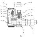
- a brake 1 for a trolley that comprises:
- the first handle 4 with the detent 5 can assume three positions corresponding to three indents 3a: a first end position, a second end position, and a middle position located between both end positions.
- the eccentric ring In the middle position, the eccentric ring is remote from the outer periphery 30 of the trolley wheel and the trolley wheel can freely rotate. In this position, the first handle 4 with the detent 5, the tension spring 8, and the stop element 9 are aligned. The tension spring 8 forces the eccentric ring 7 into the central position.
- the detent 5 of the first handle 4 can be formed of a pressure spring 5a and a ball 5b that can engage with said three indents 3a on the first axle 3.
- a shift of the first handle 4 from the middle position to the first end position causes a shift of the eccentric ring 7 such that the outer periphery of the eccentric ring contacts the outer periphery of the trolley wheel.
- the trolley wheel 30 rotates in one direction it pushes the eccentric ring 7 away from the trolley wheel 30 against the force of the tension spring 8, wherewith the rotation of the trolley wheel is enabled.
- the trolley wheel rotates in another direction it pushes the eccentric ring 7 against the trolley wheel 30 due to the blocking effect, wherewith the rotation of the trolley wheel is disabled.
- the stop element 9 leans against the inner periphery of the eccentric ring 7 and prevents further rotation of the eccentric ring around the first axle 3 and consequently too excessive blocking of the eccentric ring 7 against the trolley wheel.
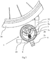
- the outer periphery of the eccentric ring 7 can be corrugated 7c, what improves the efficiency of braking in both dry and wet conditions.
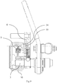
- the eccentric ring 7 can further be provided on its outer periphery by a brake pad 10.
- the brake pad 10 can be corrugated from the outer side.
- the material of the brake pad 10 can be for instance glass-fiber reinforced polychloroprene.
- the support 2 can be firmly connected with the frame of the trolley.
- Such brake is suitable to be arranged on a trolley that is already provided with a conventional bidirectional brake.
- the support 2 can be articulated with the frame 32 of the trolley.
- the middle part of the support 2 is articulated with the crank mechanism 12 with the second handle 11 which can in turn be articulated with the frame 32 of the trolley. If the second handle is shifted, the eccentric ring 7 can, while the first handle 4 is in the middle position, additionally assume the position of the bidirectional braking of the trolley wheel 30.
- the brake 1 can further comprise a cover 15, with which the eccentric ring 7 is covered.
- the brake 1 can further comprise a first 33 and a second 34 permanent magnet, wherein the first permanent magnet 33 is arranged on the first handle 4 facing the eccentric ring 7, and the second permanent magnet 34 is arranged on the eccentric ring 7 opposite the first permanent magnet 33, when the first handle 4 is in its middle position.
- the first 33 and the second 34 permanent magnets must be oriented in a way to attract each other. It is the function of the permanent magnets to prevent oscillations of the eccentric ring 7 around the first axle 3 when the trolley moves on an uneven surface (e. g. sand); the eccentric ring 7, more precisely its brake pad 10, is herewith prevented from engaging with the outer periphery of the trolley wheel, what would cause an undesired braking of the trolley.
Landscapes
- Health & Medical Sciences (AREA)
- Life Sciences & Earth Sciences (AREA)
- Animal Behavior & Ethology (AREA)
- General Health & Medical Sciences (AREA)
- Public Health (AREA)
- Veterinary Medicine (AREA)
- Engineering & Computer Science (AREA)
- Transportation (AREA)
- Mechanical Engineering (AREA)
- Braking Arrangements (AREA)
- Handcart (AREA)
- Braking Elements And Transmission Devices (AREA)
Description
- The invention refers to a trolley wheel brake, such as a wheelchair, pushchair, etc.
- Many handbrakes are known from prior art that prevent rotation of trolley wheels, thus stabilizing the position of the trolley in a certain position. Such brakes do not enable wheel braking only in one direction. This is why brakes have been developed that enable rotation of a wheel in one direction and prevent its rotation in the opposite direction. Such brake is useful when pushing/driving a trolley uphill.
- A brake of this type is known from patent
US 6253880 . The invention relates to a brake formed of a ratchet gear. The brake is fastened to the frame of the trolley and comprises an axle, a brake wheel rotatable on the axle and provided with an internal toothing, a pin movably arranged through said axle, and a lever mechanism with a first handle that enables the brake wheel to engage with the outer circumference of the trolley wheel. The internal toothing of the brake wheel and the pin are designed in a way that the pin slides on the internal toothing when the trolley wheel rotates in one direction, while the pin locks the brake wheel when the trolley rotates in the opposite direction. The trolley can thus be driven uphill, while its rearward movement is at the same time prevented. - The brake disclosed in
US 4887830 functions in a similar way. The brake can assume three positions: a first position, in which rotation of the wheelchair wheel is enabled, a second position, in which rotation of the wheelchair wheel is disabled, and a third position, in which rotation of the wheelchair wheel is disabled in one direction only. The brake comprises a crank mechanism with a first handle member for shifting the brake into one of said three positions, an axle, and a brake element pivotally mounted on the axle and optionally engaging with the peripheral surface of the wheelchair wheel. The brake element is designed in a way that the radius of the braking surface increases on the periphery. The third position of the brake enables rotation of the wheelchair wheel in one direction, while the brake element engages with the wheelchair wheel when the wheel rotates in the opposite direction, thus preventing its rotation. - A drawback of known brakes is their ability to enable unidirectional braking only in direction of the movement of a trolley. In a rearward uphill movement of a trolley, for instance, unidirectional braking of the trolley with known brakes is not enabled.
- The technical problem is to conceive a brake that will be simple in construction, reliable, and would selectively enable unidirectional braking of a trolley wheel either in forward movement or in rearward movement.
- The technical problem is solved by the brake for a trolley that comprises:
- a support connectable with its first end with a frame of the trolley,
- a first axle connected with another end of the support and peripherally provided with three indents,
- a first handle with a detent, said first handle being pivotally arranged on said first axle, wherein the first handle can assume three positions on the first axle, which are defined by the three indents,
- a pin that is firmly connected with one of its ends with the first handle and arranged parallel to the first axle at a radial distance therefrom,
- an eccentric ring with a closed bottom, in which at least an arcuate recess concentric with the first axle is formed, through which the pin projects, wherein the eccentric ring is pivotally mounted on the first axle and can engage with the outer periphery of a trolley wheel,
- a tension spring connecting the inner periphery of the eccentric ring and the pin, and
- a stop element projecting from the first axle, which can lean against the inner periphery of the eccentric ring thus preventing pivoting of the eccentric ring around the first axle in one direction.
- Based on a selection by the user, the first handle with the detent can assume three positions: a first end position, a second end position, and a middle position located between both end positions.
- In the middle position, the eccentric ring is remote from the outer periphery of the trolley wheel and the trolley wheel can freely rotate. In this position, the first handle with the detent, the tension spring, and the stop element are aligned. The tension spring forces the eccentric ring into the central position.
- A shift of the first handle from the middle position to the first end position causes a shift of the eccentric ring such that the outer periphery of the eccentric ring contacts the outer periphery of the trolley wheel. While the trolley wheel rotates in one direction it pushes the eccentric ring away from the trolley wheel against the force of the tension spring, wherewith the rotation of the trolley wheel is enabled. While the trolley wheel rotates in another direction it pushes the eccentric ring against the trolley wheel for the blocking effect, wherewith the rotation of the trolley wheel is disabled. The stop element leans against the inner periphery of the eccentric ring and prevents further rotation of the eccentric ring around the first axle and consequently too excessive blocking of the eccentric ring against the trolley wheel.
- When the first handle is shifted from the middle position to the second end position, the situation is similar to the above-identified one, only that unidirectional braking is here achieved in the opposite direction of the trolley wheel rotation.
- The support can be firmly connected with the frame of the trolley. Such brake is suitable to be arranged on a trolley that is already provided with a conventional bidirectional brake.
- In a further embodiment, the support is articulated with the frame of the trolley. In this case, the middle part of the support is articulated with the crank mechanism with the second handle which can in turn be articulated with the frame of the trolley. If the second handle is shifted, the eccentric ring can, while the first handle is in the middle position, additionally assume the position of the bidirectional braking of the trolley wheel.
- An advantage of the brake of the invention over known brakes lies in its ability to enable unidirectional braking of a trolley wheel either in forward movement or in rearward movement. A further advantage is a simple construction of the brake and its reliable operation.
-
Figure 1 : Brake in cross-section -
Figure 2 : Brake in side view -
Figure 3 : Brake with a crank mechanism in cross-section -
Figure 4 : Brake with a crank mechanism in side view -
Figure 5a : Brake in a position of unidirectional braking -
Figure 5b : Brake in a released position -
Figure 6a : Brake with a crank mechanism in a position of bidirectional braking -
Figure 6b : Brake with a crank mechanism in a position of unidirectional braking -
Figure 7 : Brake with an eccentric ring with a corrugated outer periphery -
Figure 8 : Brake with an eccentric ring with a corrugated brake pad -
Figure 9 : Brake with two permanent magnets - The invention is described in more detail hereinbelow.
- The technical problem is solved by a
brake 1 for a trolley that comprises: - a
support 2 connectable with its first end with aframe 32 of the trolley, - a
first axle 3 connected with another end of the support and peripherally provided with threeindents 3a, - a
first handle 4 with a detent 5, saidhandle 4 being pivotally arranged on saidfirst axle 3, and wherein thefirst handle 4 can assume three positions on thefirst axle 3, which are defined by the threeindents 3a, - a
pin 6 that is firmly connected with one of its ends with thefirst handle 4 and arranged parallel to thefirst axle 3 at a radial distance therefrom, - an
eccentric ring 7 with a closedbottom 7a, in which at least an arcuate recess 7b concentric with the first axle is formed, through which thepin 6 projects, wherein theeccentric ring 7 is pivotally mounted on thefirst axle 3 and engages with the outer periphery of atrolley wheel 30, - a
tension spring 8 connecting the inner periphery of theeccentric ring 7 and thepin 6, and - a
stop element 9 projecting from thefirst axle 3, which can lean against the inner periphery of theeccentric ring 7 thus preventing rotation of theeccentric ring 7 around thefirst axle 3 in one direction. - Based on a selection by the user, the
first handle 4 with thedetent 5 can assume three positions corresponding to threeindents 3a: a first end position, a second end position, and a middle position located between both end positions. - In the middle position, the eccentric ring is remote from the
outer periphery 30 of the trolley wheel and the trolley wheel can freely rotate. In this position, thefirst handle 4 with thedetent 5, thetension spring 8, and thestop element 9 are aligned. Thetension spring 8 forces theeccentric ring 7 into the central position. - The
detent 5 of thefirst handle 4 can be formed of apressure spring 5a and aball 5b that can engage with said threeindents 3a on thefirst axle 3. - A shift of the
first handle 4 from the middle position to the first end position causes a shift of theeccentric ring 7 such that the outer periphery of the eccentric ring contacts the outer periphery of the trolley wheel. While thetrolley wheel 30 rotates in one direction it pushes theeccentric ring 7 away from thetrolley wheel 30 against the force of thetension spring 8, wherewith the rotation of the trolley wheel is enabled. While the trolley wheel rotates in another direction it pushes theeccentric ring 7 against thetrolley wheel 30 due to the blocking effect, wherewith the rotation of the trolley wheel is disabled. Thestop element 9 leans against the inner periphery of theeccentric ring 7 and prevents further rotation of the eccentric ring around thefirst axle 3 and consequently too excessive blocking of theeccentric ring 7 against the trolley wheel. - When the first handle is shifted from the middle position to the second end position, the situation is similar to the above-identified one, only that unidirectional braking is here achieved in the opposite direction of the trolley wheel rotation.
- The outer periphery of the
eccentric ring 7 can be corrugated 7c, what improves the efficiency of braking in both dry and wet conditions. Theeccentric ring 7 can further be provided on its outer periphery by abrake pad 10. Thebrake pad 10 can be corrugated from the outer side. The material of thebrake pad 10 can be for instance glass-fiber reinforced polychloroprene. - The
support 2 can be firmly connected with the frame of the trolley. Such brake is suitable to be arranged on a trolley that is already provided with a conventional bidirectional brake. - In a further embodiment, the
support 2 can be articulated with theframe 32 of the trolley. In this case, the middle part of thesupport 2 is articulated with thecrank mechanism 12 with thesecond handle 11 which can in turn be articulated with theframe 32 of the trolley. If the second handle is shifted, theeccentric ring 7 can, while thefirst handle 4 is in the middle position, additionally assume the position of the bidirectional braking of thetrolley wheel 30. - The
brake 1 can further comprise acover 15, with which theeccentric ring 7 is covered. - The
brake 1 can further comprise a first 33 and a second 34 permanent magnet, wherein the firstpermanent magnet 33 is arranged on thefirst handle 4 facing theeccentric ring 7, and the secondpermanent magnet 34 is arranged on theeccentric ring 7 opposite the firstpermanent magnet 33, when thefirst handle 4 is in its middle position. The first 33 and the second 34 permanent magnets must be oriented in a way to attract each other. It is the function of the permanent magnets to prevent oscillations of theeccentric ring 7 around thefirst axle 3 when the trolley moves on an uneven surface (e. g. sand); theeccentric ring 7, more precisely itsbrake pad 10, is herewith prevented from engaging with the outer periphery of the trolley wheel, what would cause an undesired braking of the trolley.
Claims (13)
- A brake (1) for a trolley that comprises:- a support (2) connectable with its first end with a frame (32) of the trolley,- a first axle (3) connected with another end of the support and peripherally provided with three indents (3a),- a first handle (4) with a detent (5), said handle (4) being pivotally arranged on said first axle (3), and wherein the first handle (4) can assume three positions on the first axle (3), which are defined by the three indents (3a),- a pin (6) that is firmly connected with one of its ends with the first handle (4) and arranged parallel to the first axle (3) at a radial distance therefrom,- an eccentric ring (7) with a closed bottom (7a), in which at least an arcuate recess (7b) concentric with the first axle is formed, through which the pin (6) projects, wherein the eccentric ring (7) is pivotally mounted on the first axle (3) and can engage with the outer periphery of a trolley wheel (30),- a tension spring (8) connecting the inner periphery of the eccentric ring (7) and the pin (6), and- a stop element (9) projecting from the first axle (3), which can lean against the inner periphery of the eccentric ring (7) thus preventing rotation of the eccentric ring (7) around the first axle (3) in one direction.
- Brake according to claim 1, wherein, based on a selection by the user, the first handle (4) with the detent (5) can be positioned into three positions corresponding to three indents (3a): a first end position, a second end position, and a middle position located between both end positions.
- Brake according to any preceding claim, wherein the first handle (4) with the detent (5), the tension spring (8), and the stop element (9) are aligned when the first handle (4) is in the middle position.
- Brake according to any preceding claim, wherein the detent (5) of the first handle (4) is formed of a pressure spring (5a) and a ball (5b) that can engage with said three indents (3a) on the first axle (3).
- Brake according to any preceding claim, wherein the eccentric ring (7) is corrugated (7c) on its outer periphery.
- Brake according to any preceding claim, wherein the eccentric ring (7) is provided with a brake pad (10).
- Brake according to claim 6, wherein the brake pad (10) is corrugated from the outer side.
- Brake according to claim 6 or 7, wherein the brake pad (10) is formed of glass-fiber reinforced polychloroprene.
- Brake according to any preceding claim, wherein the support (2) is firmly connectable with the frame of the trolley.
- Brake according to any of claims 1 to 8, wherein the support (2) can be articulated with the frame (32) of the trolley.
- Brake according to claim 10, which further comprises a crank mechanism (12) and a second handle (11), wherein the middle part of the holder (2) is articulated via the crank mechanism (12) with the second handle (11) which can be articulated with the frame (32) of the trolley, such that by moving the second handle the eccentric ring (7) can be brought into a position of bidirectional braking of the trolley wheel (30), when the first handle (4) is in the middle position.
- Brake according to any preceding claim, which further comprises a cover (15), with which the eccentric ring (7) can be covered.
- Brake according to any preceding claim, which further comprises a first (33) and a second (34) permanent magnet, wherein the first permanent magnet (33) is arranged on the first handle (4) facing the eccentric ring (7), and the second permanent magnet (34) is arranged on the eccentric ring (7) opposite the first permanent magnet (33), when the first handle (4) is in its middle position, wherein the first (33) and the second (34) permanent magnets are oriented in a way to attract each other.
Applications Claiming Priority (2)
| Application Number | Priority Date | Filing Date | Title |
|---|---|---|---|
| SI201700223A SI25467A (en) | 2017-07-28 | 2017-07-28 | Brake |
| PCT/IB2018/054200 WO2019021071A1 (en) | 2017-07-28 | 2018-06-14 | Brake |
Publications (2)
| Publication Number | Publication Date |
|---|---|
| EP3658097A1 EP3658097A1 (en) | 2020-06-03 |
| EP3658097B1 true EP3658097B1 (en) | 2021-09-15 |
Family
ID=62705626
Family Applications (1)
| Application Number | Title | Priority Date | Filing Date |
|---|---|---|---|
| EP18733346.3A Active EP3658097B1 (en) | 2017-07-28 | 2018-06-14 | Brake |
Country Status (7)
| Country | Link |
|---|---|
| US (1) | US20200146907A1 (en) |
| EP (1) | EP3658097B1 (en) |
| JP (1) | JP7190126B2 (en) |
| CA (1) | CA3070192A1 (en) |
| ES (1) | ES2898756T3 (en) |
| SI (1) | SI25467A (en) |
| WO (1) | WO2019021071A1 (en) |
Families Citing this family (2)
| Publication number | Priority date | Publication date | Assignee | Title |
|---|---|---|---|---|
| US11559446B2 (en) * | 2019-11-06 | 2023-01-24 | Gerald M. Steiner | Anti-rollback braking system for wheelchairs |
| CN119606663B (en) * | 2024-11-01 | 2025-12-26 | 东风汽车集团股份有限公司 | A driving control device and an automatic driving equipment |
Family Cites Families (9)
| Publication number | Priority date | Publication date | Assignee | Title |
|---|---|---|---|---|
| US4887830A (en) | 1988-03-29 | 1989-12-19 | Invacare Corporation | Wheelchair with combined wheel lock and hill holder |
| NZ225630A (en) * | 1988-08-01 | 1991-03-26 | Barrie John Boyes | Hand brake with two-way directional braking |
| JPH11313855A (en) * | 1998-05-01 | 1999-11-16 | Mitsuyoshi Yamaguchi | Prevention device of backward movement of wheelchair |
| JP3071787U (en) * | 1999-11-29 | 2000-09-22 | 礼子 熊谷 | A device that allows one direction or the direction of rotation of the wheelchair tire to rotate forward or reverse. |
| JP2001247029A (en) * | 2000-03-06 | 2001-09-11 | Takahiro Kogyo Kk | Braking device |
| US6253880B1 (en) | 2000-09-05 | 2001-07-03 | Wade A. Faber | Wheel chair ratchet brake |
| DE10049120B4 (en) * | 2000-09-22 | 2004-09-02 | Uwe Lehmann | Wheelchair brakes |
| US6655503B1 (en) * | 2002-05-17 | 2003-12-02 | Thomas O. Moody | Anti-rollback brake |
| JP2008289591A (en) * | 2007-05-23 | 2008-12-04 | Karasawa Seisakusho:Kk | Brake for wheelchair |
-
2017
- 2017-07-28 SI SI201700223A patent/SI25467A/en not_active IP Right Cessation
-
2018
- 2018-06-14 US US16/631,871 patent/US20200146907A1/en not_active Abandoned
- 2018-06-14 WO PCT/IB2018/054200 patent/WO2019021071A1/en not_active Ceased
- 2018-06-14 ES ES18733346T patent/ES2898756T3/en active Active
- 2018-06-14 JP JP2020526708A patent/JP7190126B2/en active Active
- 2018-06-14 EP EP18733346.3A patent/EP3658097B1/en active Active
- 2018-06-14 CA CA3070192A patent/CA3070192A1/en active Pending
Also Published As
| Publication number | Publication date |
|---|---|
| SI25467A (en) | 2019-01-31 |
| CA3070192A1 (en) | 2019-01-31 |
| ES2898756T3 (en) | 2022-03-08 |
| JP7190126B2 (en) | 2022-12-15 |
| WO2019021071A1 (en) | 2019-01-31 |
| US20200146907A1 (en) | 2020-05-14 |
| JP2020528812A (en) | 2020-10-01 |
| EP3658097A1 (en) | 2020-06-03 |
Similar Documents
| Publication | Publication Date | Title |
|---|---|---|
| US7537093B2 (en) | Brake device for pushcart | |
| EP3658097B1 (en) | Brake | |
| CN105216547A (en) | With the castor of drg | |
| CN110709258B (en) | Suspension castor with brake lever and fork having common pivot axis and yoke portion | |
| JP2005502410A5 (en) | ||
| US3486586A (en) | Pedal crank actuated bicycle wheel rim brakes | |
| EP2065289A2 (en) | A brake device for prams | |
| US2996306A (en) | Roller skate provided with propulsion means | |
| CN217754016U (en) | Damping type rear derailleur and bicycle | |
| TWI823934B (en) | Cable adjuster and rim brake | |
| KR20140067917A (en) | Bicycle transmission | |
| US7895914B2 (en) | Command device for a bicycle gear change | |
| JP5236416B2 (en) | Caster with brake | |
| WO2008047088A2 (en) | Propulsion apparatus | |
| US3974712A (en) | Auxiliary brake lever | |
| EP2711581A1 (en) | Hub for bicycle wheels | |
| KR20110006888A (en) | Gear Assembly for Vehicle | |
| EP2269904A1 (en) | Gear assembly for transportation tools | |
| KR101193597B1 (en) | Bicycle transmission | |
| US20110017565A1 (en) | Gear assembly for transportation tools | |
| KR100654924B1 (en) | Safety switch device for one-way clutch operation | |
| KR100654925B1 (en) | Safety switch device for one-way clutch operation | |
| US6142264A (en) | Brake device for children's vehicle | |
| US20030155192A1 (en) | Unidirectional adjustment mechanism for a disk used in a bicycle | |
| CN119837715A (en) | Automatic brake for manual wheelchair |
Legal Events
| Date | Code | Title | Description |
|---|---|---|---|
| STAA | Information on the status of an ep patent application or granted ep patent |
Free format text: STATUS: UNKNOWN |
|
| STAA | Information on the status of an ep patent application or granted ep patent |
Free format text: STATUS: THE INTERNATIONAL PUBLICATION HAS BEEN MADE |
|
| PUAI | Public reference made under article 153(3) epc to a published international application that has entered the european phase |
Free format text: ORIGINAL CODE: 0009012 |
|
| STAA | Information on the status of an ep patent application or granted ep patent |
Free format text: STATUS: REQUEST FOR EXAMINATION WAS MADE |
|
| 17P | Request for examination filed |
Effective date: 20200121 |
|
| AK | Designated contracting states |
Kind code of ref document: A1 Designated state(s): AL AT BE BG CH CY CZ DE DK EE ES FI FR GB GR HR HU IE IS IT LI LT LU LV MC MK MT NL NO PL PT RO RS SE SI SK SM TR |
|
| AX | Request for extension of the european patent |
Extension state: BA ME |
|
| RAP1 | Party data changed (applicant data changed or rights of an application transferred) |
Owner name: DEZZIV D.O.O. |
|
| RIN1 | Information on inventor provided before grant (corrected) |
Inventor name: STAKNE, JOZEF |
|
| DAV | Request for validation of the european patent (deleted) | ||
| DAX | Request for extension of the european patent (deleted) | ||
| GRAP | Despatch of communication of intention to grant a patent |
Free format text: ORIGINAL CODE: EPIDOSNIGR1 |
|
| STAA | Information on the status of an ep patent application or granted ep patent |
Free format text: STATUS: GRANT OF PATENT IS INTENDED |
|
| INTG | Intention to grant announced |
Effective date: 20210426 |
|
| GRAS | Grant fee paid |
Free format text: ORIGINAL CODE: EPIDOSNIGR3 |
|
| GRAA | (expected) grant |
Free format text: ORIGINAL CODE: 0009210 |
|
| STAA | Information on the status of an ep patent application or granted ep patent |
Free format text: STATUS: THE PATENT HAS BEEN GRANTED |
|
| AK | Designated contracting states |
Kind code of ref document: B1 Designated state(s): AL AT BE BG CH CY CZ DE DK EE ES FI FR GB GR HR HU IE IS IT LI LT LU LV MC MK MT NL NO PL PT RO RS SE SI SK SM TR |
|
| REG | Reference to a national code |
Ref country code: CH Ref legal event code: EP |
|
| REG | Reference to a national code |
Ref country code: DE Ref legal event code: R096 Ref document number: 602018023607 Country of ref document: DE |
|
| REG | Reference to a national code |
Ref country code: IE Ref legal event code: FG4D |
|
| REG | Reference to a national code |
Ref country code: AT Ref legal event code: REF Ref document number: 1429968 Country of ref document: AT Kind code of ref document: T Effective date: 20211015 |
|
| REG | Reference to a national code |
Ref country code: NL Ref legal event code: FP |
|
| REG | Reference to a national code |
Ref country code: LT Ref legal event code: MG9D |
|
| PG25 | Lapsed in a contracting state [announced via postgrant information from national office to epo] |
Ref country code: LT Free format text: LAPSE BECAUSE OF FAILURE TO SUBMIT A TRANSLATION OF THE DESCRIPTION OR TO PAY THE FEE WITHIN THE PRESCRIBED TIME-LIMIT Effective date: 20210915 Ref country code: BG Free format text: LAPSE BECAUSE OF FAILURE TO SUBMIT A TRANSLATION OF THE DESCRIPTION OR TO PAY THE FEE WITHIN THE PRESCRIBED TIME-LIMIT Effective date: 20211215 Ref country code: NO Free format text: LAPSE BECAUSE OF FAILURE TO SUBMIT A TRANSLATION OF THE DESCRIPTION OR TO PAY THE FEE WITHIN THE PRESCRIBED TIME-LIMIT Effective date: 20211215 Ref country code: HR Free format text: LAPSE BECAUSE OF FAILURE TO SUBMIT A TRANSLATION OF THE DESCRIPTION OR TO PAY THE FEE WITHIN THE PRESCRIBED TIME-LIMIT Effective date: 20210915 Ref country code: FI Free format text: LAPSE BECAUSE OF FAILURE TO SUBMIT A TRANSLATION OF THE DESCRIPTION OR TO PAY THE FEE WITHIN THE PRESCRIBED TIME-LIMIT Effective date: 20210915 Ref country code: SE Free format text: LAPSE BECAUSE OF FAILURE TO SUBMIT A TRANSLATION OF THE DESCRIPTION OR TO PAY THE FEE WITHIN THE PRESCRIBED TIME-LIMIT Effective date: 20210915 Ref country code: RS Free format text: LAPSE BECAUSE OF FAILURE TO SUBMIT A TRANSLATION OF THE DESCRIPTION OR TO PAY THE FEE WITHIN THE PRESCRIBED TIME-LIMIT Effective date: 20210915 |
|
| REG | Reference to a national code |
Ref country code: AT Ref legal event code: MK05 Ref document number: 1429968 Country of ref document: AT Kind code of ref document: T Effective date: 20210915 |
|
| PG25 | Lapsed in a contracting state [announced via postgrant information from national office to epo] |
Ref country code: LV Free format text: LAPSE BECAUSE OF FAILURE TO SUBMIT A TRANSLATION OF THE DESCRIPTION OR TO PAY THE FEE WITHIN THE PRESCRIBED TIME-LIMIT Effective date: 20210915 Ref country code: GR Free format text: LAPSE BECAUSE OF FAILURE TO SUBMIT A TRANSLATION OF THE DESCRIPTION OR TO PAY THE FEE WITHIN THE PRESCRIBED TIME-LIMIT Effective date: 20211216 |
|
| REG | Reference to a national code |
Ref country code: ES Ref legal event code: FG2A Ref document number: 2898756 Country of ref document: ES Kind code of ref document: T3 Effective date: 20220308 |
|
| PG25 | Lapsed in a contracting state [announced via postgrant information from national office to epo] |
Ref country code: AT Free format text: LAPSE BECAUSE OF FAILURE TO SUBMIT A TRANSLATION OF THE DESCRIPTION OR TO PAY THE FEE WITHIN THE PRESCRIBED TIME-LIMIT Effective date: 20210915 |
|
| PG25 | Lapsed in a contracting state [announced via postgrant information from national office to epo] |
Ref country code: IS Free format text: LAPSE BECAUSE OF FAILURE TO SUBMIT A TRANSLATION OF THE DESCRIPTION OR TO PAY THE FEE WITHIN THE PRESCRIBED TIME-LIMIT Effective date: 20220115 Ref country code: SM Free format text: LAPSE BECAUSE OF FAILURE TO SUBMIT A TRANSLATION OF THE DESCRIPTION OR TO PAY THE FEE WITHIN THE PRESCRIBED TIME-LIMIT Effective date: 20210915 Ref country code: SK Free format text: LAPSE BECAUSE OF FAILURE TO SUBMIT A TRANSLATION OF THE DESCRIPTION OR TO PAY THE FEE WITHIN THE PRESCRIBED TIME-LIMIT Effective date: 20210915 Ref country code: RO Free format text: LAPSE BECAUSE OF FAILURE TO SUBMIT A TRANSLATION OF THE DESCRIPTION OR TO PAY THE FEE WITHIN THE PRESCRIBED TIME-LIMIT Effective date: 20210915 Ref country code: PT Free format text: LAPSE BECAUSE OF FAILURE TO SUBMIT A TRANSLATION OF THE DESCRIPTION OR TO PAY THE FEE WITHIN THE PRESCRIBED TIME-LIMIT Effective date: 20220117 Ref country code: PL Free format text: LAPSE BECAUSE OF FAILURE TO SUBMIT A TRANSLATION OF THE DESCRIPTION OR TO PAY THE FEE WITHIN THE PRESCRIBED TIME-LIMIT Effective date: 20210915 Ref country code: EE Free format text: LAPSE BECAUSE OF FAILURE TO SUBMIT A TRANSLATION OF THE DESCRIPTION OR TO PAY THE FEE WITHIN THE PRESCRIBED TIME-LIMIT Effective date: 20210915 Ref country code: CZ Free format text: LAPSE BECAUSE OF FAILURE TO SUBMIT A TRANSLATION OF THE DESCRIPTION OR TO PAY THE FEE WITHIN THE PRESCRIBED TIME-LIMIT Effective date: 20210915 Ref country code: AL Free format text: LAPSE BECAUSE OF FAILURE TO SUBMIT A TRANSLATION OF THE DESCRIPTION OR TO PAY THE FEE WITHIN THE PRESCRIBED TIME-LIMIT Effective date: 20210915 |
|
| REG | Reference to a national code |
Ref country code: DE Ref legal event code: R097 Ref document number: 602018023607 Country of ref document: DE |
|
| PLBE | No opposition filed within time limit |
Free format text: ORIGINAL CODE: 0009261 |
|
| STAA | Information on the status of an ep patent application or granted ep patent |
Free format text: STATUS: NO OPPOSITION FILED WITHIN TIME LIMIT |
|
| PG25 | Lapsed in a contracting state [announced via postgrant information from national office to epo] |
Ref country code: DK Free format text: LAPSE BECAUSE OF FAILURE TO SUBMIT A TRANSLATION OF THE DESCRIPTION OR TO PAY THE FEE WITHIN THE PRESCRIBED TIME-LIMIT Effective date: 20210915 |
|
| PGFP | Annual fee paid to national office [announced via postgrant information from national office to epo] |
Ref country code: NL Payment date: 20220621 Year of fee payment: 5 Ref country code: GB Payment date: 20220606 Year of fee payment: 5 |
|
| 26N | No opposition filed |
Effective date: 20220616 |
|
| PG25 | Lapsed in a contracting state [announced via postgrant information from national office to epo] |
Ref country code: SI Free format text: LAPSE BECAUSE OF FAILURE TO SUBMIT A TRANSLATION OF THE DESCRIPTION OR TO PAY THE FEE WITHIN THE PRESCRIBED TIME-LIMIT Effective date: 20210915 |
|
| PGFP | Annual fee paid to national office [announced via postgrant information from national office to epo] |
Ref country code: CH Payment date: 20220629 Year of fee payment: 5 Ref country code: BE Payment date: 20220621 Year of fee payment: 5 |
|
| PGFP | Annual fee paid to national office [announced via postgrant information from national office to epo] |
Ref country code: IT Payment date: 20220630 Year of fee payment: 5 Ref country code: ES Payment date: 20220719 Year of fee payment: 5 |
|
| PG25 | Lapsed in a contracting state [announced via postgrant information from national office to epo] |
Ref country code: MC Free format text: LAPSE BECAUSE OF FAILURE TO SUBMIT A TRANSLATION OF THE DESCRIPTION OR TO PAY THE FEE WITHIN THE PRESCRIBED TIME-LIMIT Effective date: 20210915 |
|
| PG25 | Lapsed in a contracting state [announced via postgrant information from national office to epo] |
Ref country code: LU Free format text: LAPSE BECAUSE OF NON-PAYMENT OF DUE FEES Effective date: 20220614 Ref country code: IE Free format text: LAPSE BECAUSE OF NON-PAYMENT OF DUE FEES Effective date: 20220614 |
|
| PGFP | Annual fee paid to national office [announced via postgrant information from national office to epo] |
Ref country code: FR Payment date: 20230630 Year of fee payment: 6 Ref country code: DE Payment date: 20230620 Year of fee payment: 6 |
|
| REG | Reference to a national code |
Ref country code: CH Ref legal event code: PL |
|
| REG | Reference to a national code |
Ref country code: NL Ref legal event code: MM Effective date: 20230701 |
|
| REG | Reference to a national code |
Ref country code: BE Ref legal event code: MM Effective date: 20230630 |
|
| GBPC | Gb: european patent ceased through non-payment of renewal fee |
Effective date: 20230614 |
|
| PG25 | Lapsed in a contracting state [announced via postgrant information from national office to epo] |
Ref country code: NL Free format text: LAPSE BECAUSE OF NON-PAYMENT OF DUE FEES Effective date: 20230701 |
|
| PG25 | Lapsed in a contracting state [announced via postgrant information from national office to epo] |
Ref country code: MK Free format text: LAPSE BECAUSE OF FAILURE TO SUBMIT A TRANSLATION OF THE DESCRIPTION OR TO PAY THE FEE WITHIN THE PRESCRIBED TIME-LIMIT Effective date: 20210915 Ref country code: CY Free format text: LAPSE BECAUSE OF FAILURE TO SUBMIT A TRANSLATION OF THE DESCRIPTION OR TO PAY THE FEE WITHIN THE PRESCRIBED TIME-LIMIT Effective date: 20210915 Ref country code: GB Free format text: LAPSE BECAUSE OF NON-PAYMENT OF DUE FEES Effective date: 20230614 Ref country code: CH Free format text: LAPSE BECAUSE OF NON-PAYMENT OF DUE FEES Effective date: 20230630 |
|
| PG25 | Lapsed in a contracting state [announced via postgrant information from national office to epo] |
Ref country code: HU Free format text: LAPSE BECAUSE OF FAILURE TO SUBMIT A TRANSLATION OF THE DESCRIPTION OR TO PAY THE FEE WITHIN THE PRESCRIBED TIME-LIMIT; INVALID AB INITIO Effective date: 20180614 Ref country code: BE Free format text: LAPSE BECAUSE OF NON-PAYMENT OF DUE FEES Effective date: 20230630 |
|
| REG | Reference to a national code |
Ref country code: ES Ref legal event code: FD2A Effective date: 20240729 |
|
| PG25 | Lapsed in a contracting state [announced via postgrant information from national office to epo] |
Ref country code: IT Free format text: LAPSE BECAUSE OF NON-PAYMENT OF DUE FEES Effective date: 20230614 |
|
| PG25 | Lapsed in a contracting state [announced via postgrant information from national office to epo] |
Ref country code: MT Free format text: LAPSE BECAUSE OF FAILURE TO SUBMIT A TRANSLATION OF THE DESCRIPTION OR TO PAY THE FEE WITHIN THE PRESCRIBED TIME-LIMIT Effective date: 20210915 |
|
| PG25 | Lapsed in a contracting state [announced via postgrant information from national office to epo] |
Ref country code: ES Free format text: LAPSE BECAUSE OF NON-PAYMENT OF DUE FEES Effective date: 20230615 |
|
| PG25 | Lapsed in a contracting state [announced via postgrant information from national office to epo] |
Ref country code: ES Free format text: LAPSE BECAUSE OF NON-PAYMENT OF DUE FEES Effective date: 20230615 |
|
| REG | Reference to a national code |
Ref country code: DE Ref legal event code: R119 Ref document number: 602018023607 Country of ref document: DE |
|
| PG25 | Lapsed in a contracting state [announced via postgrant information from national office to epo] |
Ref country code: DE Free format text: LAPSE BECAUSE OF NON-PAYMENT OF DUE FEES Effective date: 20250101 |
|
| PG25 | Lapsed in a contracting state [announced via postgrant information from national office to epo] |
Ref country code: FR Free format text: LAPSE BECAUSE OF NON-PAYMENT OF DUE FEES Effective date: 20240630 |
|
| PG25 | Lapsed in a contracting state [announced via postgrant information from national office to epo] |
Ref country code: TR Free format text: LAPSE BECAUSE OF FAILURE TO SUBMIT A TRANSLATION OF THE DESCRIPTION OR TO PAY THE FEE WITHIN THE PRESCRIBED TIME-LIMIT Effective date: 20210915 |