EP3658053B1 - Minimally invasive articulating assembly having ablation capabilities - Google Patents
Minimally invasive articulating assembly having ablation capabilities Download PDFInfo
- Publication number
- EP3658053B1 EP3658053B1 EP18839345.8A EP18839345A EP3658053B1 EP 3658053 B1 EP3658053 B1 EP 3658053B1 EP 18839345 A EP18839345 A EP 18839345A EP 3658053 B1 EP3658053 B1 EP 3658053B1
- Authority
- EP
- European Patent Office
- Prior art keywords
- ports
- distal
- assembly
- ablation
- conductive
- Prior art date
- Legal status (The legal status is an assumption and is not a legal conclusion. Google has not performed a legal analysis and makes no representation as to the accuracy of the status listed.)
- Active
Links
Images








Classifications
-
- A—HUMAN NECESSITIES
- A61—MEDICAL OR VETERINARY SCIENCE; HYGIENE
- A61B—DIAGNOSIS; SURGERY; IDENTIFICATION
- A61B18/00—Surgical instruments, devices or methods for transferring non-mechanical forms of energy to or from the body
- A61B18/04—Surgical instruments, devices or methods for transferring non-mechanical forms of energy to or from the body by heating
- A61B18/12—Surgical instruments, devices or methods for transferring non-mechanical forms of energy to or from the body by heating by passing a current through the tissue to be heated, e.g. high-frequency current
- A61B18/1206—Generators therefor
-
- A—HUMAN NECESSITIES
- A61—MEDICAL OR VETERINARY SCIENCE; HYGIENE
- A61B—DIAGNOSIS; SURGERY; IDENTIFICATION
- A61B18/00—Surgical instruments, devices or methods for transferring non-mechanical forms of energy to or from the body
- A61B18/04—Surgical instruments, devices or methods for transferring non-mechanical forms of energy to or from the body by heating
- A61B18/12—Surgical instruments, devices or methods for transferring non-mechanical forms of energy to or from the body by heating by passing a current through the tissue to be heated, e.g. high-frequency current
- A61B18/14—Probes or electrodes therefor
- A61B18/1492—Probes or electrodes therefor having a flexible, catheter-like structure, e.g. for heart ablation
-
- A—HUMAN NECESSITIES
- A61—MEDICAL OR VETERINARY SCIENCE; HYGIENE
- A61B—DIAGNOSIS; SURGERY; IDENTIFICATION
- A61B90/00—Instruments, implements or accessories specially adapted for surgery or diagnosis and not covered by any of the groups A61B1/00 - A61B50/00, e.g. for luxation treatment or for protecting wound edges
- A61B90/36—Image-producing devices or illumination devices not otherwise provided for
- A61B90/37—Surgical systems with images on a monitor during operation
-
- A—HUMAN NECESSITIES
- A61—MEDICAL OR VETERINARY SCIENCE; HYGIENE
- A61B—DIAGNOSIS; SURGERY; IDENTIFICATION
- A61B18/00—Surgical instruments, devices or methods for transferring non-mechanical forms of energy to or from the body
- A61B2018/00053—Mechanical features of the instrument of device
- A61B2018/00214—Expandable means emitting energy, e.g. by elements carried thereon
- A61B2018/0022—Balloons
- A61B2018/0025—Multiple balloons
-
- A—HUMAN NECESSITIES
- A61—MEDICAL OR VETERINARY SCIENCE; HYGIENE
- A61B—DIAGNOSIS; SURGERY; IDENTIFICATION
- A61B18/00—Surgical instruments, devices or methods for transferring non-mechanical forms of energy to or from the body
- A61B2018/00053—Mechanical features of the instrument of device
- A61B2018/00214—Expandable means emitting energy, e.g. by elements carried thereon
- A61B2018/0022—Balloons
- A61B2018/0025—Multiple balloons
- A61B2018/00255—Multiple balloons arranged one inside another
-
- A—HUMAN NECESSITIES
- A61—MEDICAL OR VETERINARY SCIENCE; HYGIENE
- A61B—DIAGNOSIS; SURGERY; IDENTIFICATION
- A61B18/00—Surgical instruments, devices or methods for transferring non-mechanical forms of energy to or from the body
- A61B2018/00315—Surgical instruments, devices or methods for transferring non-mechanical forms of energy to or from the body for treatment of particular body parts
- A61B2018/00541—Lung or bronchi
-
- A—HUMAN NECESSITIES
- A61—MEDICAL OR VETERINARY SCIENCE; HYGIENE
- A61B—DIAGNOSIS; SURGERY; IDENTIFICATION
- A61B18/00—Surgical instruments, devices or methods for transferring non-mechanical forms of energy to or from the body
- A61B2018/00571—Surgical instruments, devices or methods for transferring non-mechanical forms of energy to or from the body for achieving a particular surgical effect
- A61B2018/00577—Ablation
-
- A—HUMAN NECESSITIES
- A61—MEDICAL OR VETERINARY SCIENCE; HYGIENE
- A61B—DIAGNOSIS; SURGERY; IDENTIFICATION
- A61B18/00—Surgical instruments, devices or methods for transferring non-mechanical forms of energy to or from the body
- A61B2018/00636—Sensing and controlling the application of energy
- A61B2018/00773—Sensed parameters
- A61B2018/00791—Temperature
-
- A—HUMAN NECESSITIES
- A61—MEDICAL OR VETERINARY SCIENCE; HYGIENE
- A61B—DIAGNOSIS; SURGERY; IDENTIFICATION
- A61B18/00—Surgical instruments, devices or methods for transferring non-mechanical forms of energy to or from the body
- A61B2018/00636—Sensing and controlling the application of energy
- A61B2018/00773—Sensed parameters
- A61B2018/00875—Resistance or impedance
-
- A—HUMAN NECESSITIES
- A61—MEDICAL OR VETERINARY SCIENCE; HYGIENE
- A61B—DIAGNOSIS; SURGERY; IDENTIFICATION
- A61B18/00—Surgical instruments, devices or methods for transferring non-mechanical forms of energy to or from the body
- A61B18/04—Surgical instruments, devices or methods for transferring non-mechanical forms of energy to or from the body by heating
- A61B18/12—Surgical instruments, devices or methods for transferring non-mechanical forms of energy to or from the body by heating by passing a current through the tissue to be heated, e.g. high-frequency current
- A61B18/1206—Generators therefor
- A61B2018/1246—Generators therefor characterised by the output polarity
-
- A—HUMAN NECESSITIES
- A61—MEDICAL OR VETERINARY SCIENCE; HYGIENE
- A61B—DIAGNOSIS; SURGERY; IDENTIFICATION
- A61B18/00—Surgical instruments, devices or methods for transferring non-mechanical forms of energy to or from the body
- A61B18/04—Surgical instruments, devices or methods for transferring non-mechanical forms of energy to or from the body by heating
- A61B18/12—Surgical instruments, devices or methods for transferring non-mechanical forms of energy to or from the body by heating by passing a current through the tissue to be heated, e.g. high-frequency current
- A61B18/1206—Generators therefor
- A61B2018/1246—Generators therefor characterised by the output polarity
- A61B2018/1253—Generators therefor characterised by the output polarity monopolar
-
- A—HUMAN NECESSITIES
- A61—MEDICAL OR VETERINARY SCIENCE; HYGIENE
- A61B—DIAGNOSIS; SURGERY; IDENTIFICATION
- A61B18/00—Surgical instruments, devices or methods for transferring non-mechanical forms of energy to or from the body
- A61B18/04—Surgical instruments, devices or methods for transferring non-mechanical forms of energy to or from the body by heating
- A61B18/12—Surgical instruments, devices or methods for transferring non-mechanical forms of energy to or from the body by heating by passing a current through the tissue to be heated, e.g. high-frequency current
- A61B18/1206—Generators therefor
- A61B2018/1246—Generators therefor characterised by the output polarity
- A61B2018/126—Generators therefor characterised by the output polarity bipolar
-
- A—HUMAN NECESSITIES
- A61—MEDICAL OR VETERINARY SCIENCE; HYGIENE
- A61B—DIAGNOSIS; SURGERY; IDENTIFICATION
- A61B18/00—Surgical instruments, devices or methods for transferring non-mechanical forms of energy to or from the body
- A61B18/04—Surgical instruments, devices or methods for transferring non-mechanical forms of energy to or from the body by heating
- A61B18/12—Surgical instruments, devices or methods for transferring non-mechanical forms of energy to or from the body by heating by passing a current through the tissue to be heated, e.g. high-frequency current
- A61B18/14—Probes or electrodes therefor
- A61B2018/1472—Probes or electrodes therefor for use with liquid electrolyte, e.g. virtual electrodes
-
- A—HUMAN NECESSITIES
- A61—MEDICAL OR VETERINARY SCIENCE; HYGIENE
- A61B—DIAGNOSIS; SURGERY; IDENTIFICATION
- A61B90/00—Instruments, implements or accessories specially adapted for surgery or diagnosis and not covered by any of the groups A61B1/00 - A61B50/00, e.g. for luxation treatment or for protecting wound edges
- A61B90/36—Image-producing devices or illumination devices not otherwise provided for
- A61B90/37—Surgical systems with images on a monitor during operation
- A61B2090/376—Surgical systems with images on a monitor during operation using X-rays, e.g. fluoroscopy
-
- A—HUMAN NECESSITIES
- A61—MEDICAL OR VETERINARY SCIENCE; HYGIENE
- A61B—DIAGNOSIS; SURGERY; IDENTIFICATION
- A61B90/00—Instruments, implements or accessories specially adapted for surgery or diagnosis and not covered by any of the groups A61B1/00 - A61B50/00, e.g. for luxation treatment or for protecting wound edges
- A61B90/36—Image-producing devices or illumination devices not otherwise provided for
- A61B90/37—Surgical systems with images on a monitor during operation
- A61B2090/376—Surgical systems with images on a monitor during operation using X-rays, e.g. fluoroscopy
- A61B2090/3762—Surgical systems with images on a monitor during operation using X-rays, e.g. fluoroscopy using computed tomography systems [CT]
-
- A—HUMAN NECESSITIES
- A61—MEDICAL OR VETERINARY SCIENCE; HYGIENE
- A61B—DIAGNOSIS; SURGERY; IDENTIFICATION
- A61B90/00—Instruments, implements or accessories specially adapted for surgery or diagnosis and not covered by any of the groups A61B1/00 - A61B50/00, e.g. for luxation treatment or for protecting wound edges
- A61B90/36—Image-producing devices or illumination devices not otherwise provided for
- A61B90/37—Surgical systems with images on a monitor during operation
- A61B2090/378—Surgical systems with images on a monitor during operation using ultrasound
-
- A—HUMAN NECESSITIES
- A61—MEDICAL OR VETERINARY SCIENCE; HYGIENE
- A61B—DIAGNOSIS; SURGERY; IDENTIFICATION
- A61B2218/00—Details of surgical instruments, devices or methods for transferring non-mechanical forms of energy to or from the body
- A61B2218/001—Details of surgical instruments, devices or methods for transferring non-mechanical forms of energy to or from the body having means for irrigation and/or aspiration of substances to and/or from the surgical site
- A61B2218/002—Irrigation
Definitions
- the present disclosure relates generally to medical devices for ablating tissue, and, more particularly, to a minimally invasive articulating assembly including a delivery device in the form of a guide sheath configured to be advanced through tortuous anatomy, within a lung, and deliver at least two separate steerable and expandable ablation devices to a target site located at a bifurcated section within the lung (e.g., bronchial airway bifurcation), wherein the expandable ablation devices are configured to be deployed and cooperatively controlled so as to apply compression and/or energy emission to the target tissue for subsequent ablation thereof.
- a delivery device in the form of a guide sheath configured to be advanced through tortuous anatomy, within a lung, and deliver at least two separate steerable and expandable ablation devices to a target site located at a bifurcated section within the lung (e.g., bronchial airway bifurcation), wherein the expandable ablation devices are configured to be deployed and cooperatively controlled so as to apply compression and/or energy emission to the target tissue
- Ablation therapy is a type of minimally invasive procedure medical professionals (i.e., surgeons) use to destroy abnormal tissue that occurs with many conditions. For example, a doctor might use an ablation procedure to treat a cancerous tumor (i.e., completely destroy cancerous tissue) or to destroy (ablate) a small amount of tissue, such as in the heart so as to prevent and/or treat abnormal heart rhythms. In some instances, ablation therapy may be particularly difficult due to the location of the abnormal tissue to be treated and the degree of preciseness required to avoid ablating adjacent healthy tissue, such as diseases of the lung.
- emphysema is a lung condition that causes shortness of breath.
- the air sacs in the lungs (alveoli) are damaged. Over time, the inner walls of the air sacs weaken and rupture, thereby creating larger air spaces instead of many small ones, which reduces the surface area of the lungs and, in turn, the amount of oxygen that reaches the bloodstream.
- LVR Lung Volume Reduction
- Such a procedure allows healthier lung tissue to expand into the volume previously occupied by the diseased tissue and allows the diaphragm to recover.
- high mortality and morbidity may be associated with this invasive procedure.
- US2014018788 A1 discloses methods and endovascular catheters for assessing, and treating patients having sympathetically mediated disease, involving augmented peripheral chemoreflex and heightened sympathetic tone by reducing chemosensor input to the nervous system via transmural carotid body ablation.
- US2017119454 A1 discloses an ablation device having a screen sphere configuration for the ablation of marginal tissue surrounding a tissue cavity.
- the device includes a probe having a nonconductive elongated shaft including at least one lumen therethrough and a nonconductive distal portion extending from the shaft.
- the nonconductive distal portion includes a plurality distal ports and a plurality of proximal ports in communication with the at least one lumen of the shaft.
- the device further includes an electrode array including a plurality of independent conductive wires extending through the lumen and positioned along an external surface of the nonconductive distal portion, each of the plurality of wires passes through at least an associated one of the proximal ports and through at least a corresponding one of the distal ports.
- US2016317221 A1 discloses tissue ablation system including an ablation device having a deployable applicator head configured to be delivered to a tissue cavity and ablate marginal tissue surrounding the tissue cavity.
- the deployable applicator head is configured to be delivered to a tissue cavity while in a collapsed configuration and ablate marginal tissue surrounding the tissue cavity while in an expanded configuration.
- a minimally invasive medical assembly as defined in independent claim 1.
- a minimally invasive medical assembly as defined in independent claim 2.
- Optional and/or preferable features are defined in the dependent claims.
- a first one of the ablation devices is steerable towards a first pathway extending from the bifurcation and a second one of the ablation devices is separately steerable towards a second pathway extending from the bifurcation, such that each of the ablation devices can be positioned on either side of a target tissue proximate the bifurcation.
- the first and second ablation devices each include a distal applicator tip configured to transition between a delivery configuration, in which the applicator tip is collapsed and is shaped and sized to fit within and pass through a pathway (i.e., bronchial airway), and a deployed configuration, in which the applicator tip is expanded and is shaped and sized in such a manner so as to become lodged or anchored within the pathway and thereby apply at least a degree of compression upon the target tissue, such that the target tissue is generally compressed between the distal applicator tips.
- One or both of the distal applicator tips further includes an electrode array configured to emit RF energy upon the target tissue for subsequent ablation thereof.
- the assembly of the present invention allows for improved controlled over the ablation of tissue, particularly in normally isolated regions ((i.e., tortuous pathways in the lung), allowing for application of RF energy in a controlled manner with little or no deleterious effect on surrounding healthy tissue or organs.
- the present invention allows for debulking of diseased tissue almost immediately by way of RF ablation, such that, upon treating the diseased tissue, necrosis of such tissue is immediate and the assembly can be completely removed once the procedure is completed, and thus does not present any issues that may be present with devices requiring implantation for a given period of time.
- the present disclosure is generally directed to a minimally invasive articulating assembly configured to be delivered to a surgical site within a patient and further configured to be advanced through a tortuous anatomy to reach a target tissue and subsequently provide ablation treatment to the target tissue.
- the articulating assembly includes a delivery device in the form of a scope or other access device configured to provide access to a target site within a patient.
- the delivery device has an outer guide sheath configured to be advanced through the tortuous anatomy, particularly within a lung, and subsequently deliver at least two separately deployable and expandable ablation devices to the target site located at a bifurcated section of the lung (i.e., at a bronchial airway bifurcation) for ablation of the target tissue, which may include diseased lung tissue, including, but not limited to, a cancerous tumor or emphysema-related damaged tissue.
- a first one of the ablation devices is steerable towards a first pathway extending from the bifurcation and a second one of the ablation devices is separately steerable towards a second pathway extending from the bifurcation, such that each of the ablation devices can be positioned on either side of a target tissue proximate the bifurcation.
- the first and second ablation devices each include a distal applicator tip configured to transition between a delivery configuration, in which the applicator tip is collapsed and is shaped and sized to fit within and pass through a pathway (i.e., bronchial airway), and a deployed configuration, in which the applicator tip is expanded and is shaped and sized in such a manner so as to become lodged or anchored within the pathway and thereby apply at least a degree of compression upon the target tissue, such that the target tissue is generally compressed between the distal applicator tips.
- One or both of the distal applicator tips further includes an electrode array configured to emit RF energy upon the target tissue for subsequent ablation thereof.
- the assembly of the present invention allows for improved controlled over the ablation of tissue, particularly in normally isolated regions ((i.e., tortuous pathways in the lung), allowing for application of RF energy in a controlled manner with little or no deleterious effect on surrounding healthy tissue or organs.
- the present invention allows for debulking of diseased tissue almost immediately by way of RF ablation, such that, upon treating the diseased tissue, necrosis of such tissue is immediate and the assembly can be completely removed once the procedure is completed, and thus does not present any issues that may be present with devices requiring implantation for a given period of time.
- the following description focuses on the use of the articulating assembly within the tortuous passageways of the lung of a patient.
- the present invention can be used in any other organs which may include tortuous pathways, such as the heart or the vascular system, and which may further include bifurcations.
- FIGS. 1A and 1B are schematic illustrations of an ablation system 10 for providing ablation of diseased tissue within a patient 12.
- the ablation system 10 generally includes an articulating assembly 14, including a delivery device 15, which may be in the form of a scope or other access device configured to provide access to a target site within the patient 12.
- the delivery device 15 is configured to be advanced through the tortuous anatomy, particularly within a lung, and subsequently deliver at least two separately deployable and expandable ablation devices 16a, 16b to the target site for ablation of a target tissue, as will be described in greater detail herein.
- the articulating assembly 14, specifically each of the first and second ablation devices 16a, 16b may further be coupled to a controller 18, an ablation RF generator 20, and an irrigation pump or drip 22.
- each of the ablation devices 16a, 16b includes a distal applicator tip or portion configured to be advanced to the target site and transition between a delivery configuration, in which the tip is collapsed and shaped and sized to fit within and pass through a pathway (i.e., bronchial airway), and a deployed configuration, in which the applicator tip is expanded and is shaped and sized in such a manner so as to become lodged or anchored within the pathway and thereby apply at least a degree of compression upon the target tissue (e.g., an expanded spherical shape).
- a delivery configuration in which the tip is collapsed and shaped and sized to fit within and pass through a pathway (i.e., bronchial airway)
- a deployed configuration in which the applicator tip is expanded and is shaped and sized in such a manner so as to become lodged or anchored within the pathway and thereby apply at least a degree of compression upon the target tissue (e.g., an expanded spherical shape).
- the distal applicator tip is configured to emit non-ionizing radiation, such as radiofrequency (RF) energy, to treat the target tissue, specifically a diseased tissue, such as a cancerous tumor or emphysema-related damaged tissue within the lung.
- RF radiofrequency
- the applicator tip of each ablation device generally includes an electrode array positioned along an external surface thereof, wherein the electrode array is configured to receive an electrical current from an energy source (i.e., from the RF generator 20) and conduct energy, the energy including RF energy.
- the ablation controller 18 may be used to control the emission of energy from the electrode array of a distal tip of an ablation device 16 to result in ablation, as well as control parameters of the ablation (i.e., elapsed time, total energy output, specific energy output pattern, etc.).
- each ablation device 16 may be further configurd to provide RF ablation via a virtual electrode arrangement, which includes distribution of a fluid along an exterior surface of the distal tip and, upon activation of the electrode array, the fluid may carry, or otherwise promote, energy emitted from the electrode array to the surrounding tissue.
- the distal tip of an ablation device may include a plurality of ports or apertures configured to allow the fluid to pass therethrough, or weep, from an interior of the distal tip to an external surface of the distal tip.
- the irrigation pump or drip 22 may provide the conductive fluid (e.g., saline) to the distal tip of each ablation device.
- the RF generator 20 may generally provide RF energy (e.g., electrical energy in the radiofrequency (RF) range (e.g., 350-800 kHz)) to an electrode array of one of the ablation devices 16, as controlled by the ablation controller 18.
- RF energy e.g., electrical energy in the radiofrequency (RF) range (e.g., 350-800 kHz)
- saline may also be released from the irrigation pump or drip 22 the distal tip of the ablation device 16.
- the ablation system 10 may further include an imaging modality 24.
- the imaging modality 24 may provide an operator (e.g., surgeon) with a visual depiction of distal end of the delivery device 15 during advancement towards the target site and may further provide visual depiction of the ablation devices 16a, 16b during delivery and deployment thereof when positioning for subsequent ablation of target tissue.
- the imaging modality 24 may be configured to receive sensing input from the delivery device 15, the ablation devices 16a, 16b (e.g., sensors on the scope 15 and/or ablation devices 16a, 16b, such as ultrasound, video, images, etc.) so as to provide an accurate display to the surgeon during a procedure.
- the imaging modality 24 may provide a medical imaging procedure, including, but not limited to, ultrasound (US), wavelength detection, X-ray-based imaging, illumination, computed tomography (CT), radiography, and fluoroscopy, or a combination thereof, such that, when viewed under such a medical imaging procedure provided by the imaging modality 24, the visibility of the target site is enhanced and a surgeon can better maneuver the scope 15 and each of the first and second ablation devices 16a, 16b during a procedure.
- US ultrasound
- CT computed tomography
- FIG. 2 is a perspective view of one embodiment of a steerable and expandable ablation device 16 compatible with the articulating assembly 14.
- the ablation device 16 generally includes a guide sheath 26 sized or shaped to fit within the delivery device 15.
- the ablation device 16 further includes a distal applicator tip 28 configured to extend from a distal end of the guide sheath 26.
- the tip 28 generally includes a flexible body configured to have a collapsed configuration and entirely fit within the lumen of the guide sheath 26, such that, upon advancing the guide sheath 26 to the target site, the tip 28 can be extended from the distal end of the guide sheath 26 and the surgeon can control transitioning of the tip 28 from a delivery configuration to a deployed configuration.
- the tip 28 When in the delivery configuration (as shown in FIG. 3A ), the tip 28 is collapsed and is shaped and sized to fit within and pass through a pathway (i.e., bronchial airway).
- the tip 28 When in the deployed configuration (as shown in FIG. 3B ), the tip 28 is expanded in response to inflation of the tip 28.
- the tip 28 may include an inner balloon (not shown) configured to receive a fluid or gas via a line 30 coupled to a source controllable via a controller, such as a valve 32 or the like. Upon inflation of the inner balloon, the tip 28 may correspondingly expand to assume the deployed configuration.
- the tip 28 is further coupled to the irrigation pump or drip 22 via a fluid line 34, in which the flow of conductive fluid from the irrigation pump or drip 22 to the tip 28 may be controlled manually via a valve 36 or the like. Accordingly, the tip 28 may include a design similar to the ablation device design described in U.S. Application No. 15/142,616, filed April 29, 2016 (Publication No. 2016/0317221 ).
- the ablation device 16 is steerable by way of a pull wire or tether that is anchored to a distal end of the guide sheath 26, thereby allowing maneuverability of the tip 28 when advancing the ablation device 16 through bronchial airways.
- the pull wire or tether may be housed within a sheath 38 housing the pull wire or tether, for example.
- application of a pulling force upon the pull wire will generally result in a corresponding deflection of the distal end of the guide sheath 26, thereby allowing for the ablation device to be maneuvered past bifurcations or other obstructions.
- the ablation device 16 may further include sensors or the like to assist in providing visualization of the device to a surgeon during a procedure.
- the ablation device may include a sensor, including, for example, an ultrasound transducer positioned along the guide sheath 26 adjacent to a distal end thereof or placed upon the tip 28 body, wherein a line providing signal from the sensor may be housed within a sheath 40.
- the electrical line (not shown) coupling the RF generator 20 to an electrode array on the tip 28 may further be housed within a separate sheath (not shown).
- the tip 28 includes an electrode array is composed of a plurality of conductive members (e.g., conductive wires) 42.
- each of the plurality of conductive wires 42, or one or more sets of a combination of conductive wires 42 is configured to independently receive an electrical current from the RF generator 20 and independently conduct energy, the energy including RF energy. This allows energy to be selectively delivered to a designated conductive wire or combination of conductive wires.
- This design also enables the ablation device 16 to function in a bipolar mode because a first conductive wire (or combination of conductive wires) can deliver energy to the surrounding tissue through its electrical connection with the RF generator while a second conductive wire (or combination of conductive wiress) can function as a ground or neutral conductive member.
- the ablation device 16 is configurd to provide RF ablation via a virtual electrode arrangement, which includes distribution of a fluid along an exterior surface of the distal tip 28 and, upon activation of the electrode array, the fluid may carry, or otherwise promote, energy emitted from the electrode array to the surrounding tissue.
- the tip 28 includes an interior chamber configured to receive the conductive fluid thereoin from the fluid source.
- the tip 28 body includes a plurality of ports, ports, or apertures 44 configured to allow the fluid to pass therethrough, or weep, from the interior chamber to an external surface of the tip 28.
- the electrode array can be activated and fluid can be delivered to the tip 28.
- the fluid weeping through the ports 44 to the outer surface of the tip 28 is able to carry energy from electrode array, thereby creating a virtual electrode.
- a pool or thin film of fluid is formed on the exterior surface of the tip 28 and is configured to ablate surrounding tissue via the RF energy carried from the electrode array.
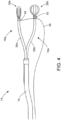
- FIG. 4 is a side view of an articulating assembly 14 illustrating a pair of steerable and expandable ablation devices 16a, 16b extended from the delivery device 15.
- the delivery device 15 may include a scope, including, but not limited to, an endoscope, laparoscope, catheter, trocar, or other delivery device.
- the delivery device 15 is an endoscope.
- the distal tip 28a of the first ablation device 16a is in the delivery configuration (i.e., collapsed shape) and the distal tip 28b of the second ablation device 16b is in the deployed configuration (i.e., expanded shape), illustrating that the ablation devices 16a, 16b can be independently controlled with regard to individual transitioning between delivery and deployed configurations.
- the second ablation device 16b may be coupled to the first ablation device 16a via the pull wire 46.
- the pull wire 46 is directly secured at one end to the distal end of the guide sheath 26a of the first ablation device 16a at an anchor point 48. Accordingly, upon application of a force upon the pull wire 46, the distal end of the guide sheath 26a corresponding deflects.
- the pull wire 46 is further coupled to the second ablation device 16b by way of a loop or hook 50 positioned at a distal end of the guide sheath 26b of the second ablation device 16b through which the pull wire 46 passes.
- a pulling force upon the pull wire 46 generally results drawing of the distal ends of the guide sheaths 26a, 26b of the first and second ablation devices 16a, 16a towards one another, which will further result in drawing together of the tips 28a, 28b.
- a surgeon need only apply a pulling force upon the pull wire 46, which results in drawing of the tips 28a, 28b towards one another, thereby compressing the target tissue between the tips 28a, 28b, at which point, one or both of the tips 28a, 28b can be used to further emit RF energy from their respective electrode arrays, in combination weeping conductive fluid, to create a virtual electrode for subsequent ablation of the target tissue.
- FIGS. 5A and 5B illustrate the positioning and movement of the articulating assembly 14 through tortuous pathways within the bronchial airways of a lung.
- the delivery device may be in the form of a scope and is configured to carry at least two ablation devices 16a, 16b for ablation of a target tissue at a target site within the lung.
- a surgeon is able to steer the delivery device 15 while advancing the assembly 15 through the bronchial passages of the lung towards the target site which includes diseased tissue, which may include, but is not limited to, a cancerous tumor or emphysema-related damaged tissue.
- Use of the imaging modality 24 allows for the surgeon to view the assembly 14 during advancement through tortuous anatomy, wherein, upon encountering obstructions, the surgeon can maneuver the scope to continue advancement.
- the surgeon can then begin delivery of the ablation devices 16a, 16b for ablation of the target tissue.
- the first ablation device 16a is steerable towards a first pathway extending from the bifurcation and the second ablation device 16b is separately steerable towards a second pathway extending from the bifurcation, such the first and second ablation devices 16a, 16b can be positioned on either side of the target tissue proximate the bifurcation.
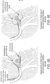
- FIG. 5D illustrates deployment of the distal applicator tips 28a, 28b of the first and second ablation devices 16a, 16b, respectively.
- a surgeon need only extend each of the tips 28a, 28b from their respective guide sheaths 26a, 26b of the corresponding ablation devices. The surgeon may then retract the pull wire 46, which, as previously described, results in drawing of the tips 28a, 28b towards one another.
- FIG. 5E illustrates transitioning of the distal applicator tips 28a, 28b from the delivery configuration to the expanded configuration, wherein each tip generally expands in diameter and becomes lodged or anchored within the respective pathways of the bronchial airway. Accordingly, upon expanding, the first and second tips 28a, 28b compress the target tissue between one another.
- ablation may begin. As shown in FIG. 5F , ablation of the target tissue occurs based on the emission of radiofrequency (RF) energy from the distal applicator tips 28a, 28b and FIG. 5G illustrates the ablated target tissue.
- RF radiofrequency
- FIG. 6A-6D illustrate an articulating assembly having a tetherless designed (i.e., the assembly does not include a pull wire or tether coupled to either of the first and second ablation devices).
- FIG. 6A illustrates positioning of the distal applicator tips of the first and second ablation devices, specifically illustrating independent movement of each applicator tip into a respective pathway extending from a bronchial airway bifurcation and further positioned on sides of a target tissue to be ablated.
- FIG. 6B illustrates deployment of the distal applicator tips of the first and second ablation devices, including advancement of the tips from the respective guide sheaths of the corresponding ablation device.
- FIG. 6C illustrates the advancement of the outer guide sheath of the delivery device towards the applicator tips, thereby resulting in the drawing of the distal applicator tips towards one another;
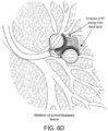
- FIG. 6D illustrates transitioning of the distal applicator tips from the delivery configuration to the expanded configuration, expanding in diameter and becoming lodged or anchored within the respective pathways of the bronchial airway and further compressing the target tissue between one another and subsequent ablation of the target tissue based on the emission of radiofrequency (RF) energy from the distal applicator tips.
- RF radiofrequency
- the assembly of the present invention allows for improved controlled over the ablation of tissue, particularly in normally isolated regions ((i.e., tortuous pathways in the lung), allowing for application of RF energy in a controlled manner with little or no deleterious effect on surrounding healthy tissue or organs.
- the present invention allows for debulking of diseased tissue almost immediately by way of RF ablation, such that, upon treating the diseased tissue, necrosis of such tissue is immediate and the assembly can be completely removed once the procedure is completed, and thus does not present any issues that may be present with devices requiring implantation for a given period of time.
- FIG. 7 is a perspective view of one embodiment of an ablation device 100 consistent with the present disclosure, including an expandable distal applicator tip 104 extending from a distal end of a handle 102, consistent with the present disclosure.
- FIG. 8 is an exploded view of the ablation device 100, specifically the distal application tip 104 of FIG. 7 .
- the applicator tip 104 includes a multiple-balloon design.
- the applicator tip 104 includes an inner balloon 106 coupled to a first fluid source via a first fluid line 30 and configured to inflate into an expanded configuration in response to the delivery of fluid (e.g., saline, air, etc.) thereto.
- the applicator tip 104 further includes an outer balloon 108 surrounding the inner balloon 106 and configured to correspondingly expand or collapse in response to expansion or collapse of the inner balloon 106.
- the inner balloon 106 may include an irregular outer surface 112, which may include a plurality of bumps, ridges, or other features, configured to maintain separation between the outer surface of the inner balloon 106 and an interior surface of the outer balloon 108, thereby ensuring that a chamber is maintained between the inner and outer balloons.
- the outer balloon 108 may be coupled to a second fluid source (or the first fluid source) via a second fluid line 34.
- the outer balloon 108 may further include a plurality of perforations, holes, or ports 114 so as to allow fluid from the second fluid source to pass therethrough, or weep, from the outer balloon 108.
- the perforations may be sized, shaped, and/or arranged in such a pattern so as to allow a volume of fluid to pass from the chamber to an exterior surface of the outer balloon at a controlled rate.
- the applicator tip 104 further includes one or more conductive elements, generally resembling electrically conductive wires or tines 110, positioned within the chamber area between the inner balloon 106 and outer balloon 108.
- the conductive elements 110 are coupled to the RF generator 20 via an electrical line 25, and configured to conduct electrical current to be carried by the fluid within the chamber from the interior surface to the exterior surface of the outer balloon 108 for ablation of a target tissue, as will be described in greater detail herein.
- the plurality of conductive wires 110 may be electrically isolated and independent from one another. This design allows for each conductive wire to receive energy in the form of electrical current from a source (e.g., RF generator) and emit RF energy in response.
- the system may include a device controller 18, for example, configured to selectively control the supply of electrical current to each of the conductive wires 110.
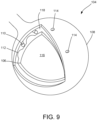
- FIG. 9 is a perspective view, partly in section, of the distal applicator tip 104.
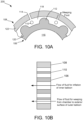
- FIGS. 10A and 10B are sectional views of a portion of the distal applicator tip 104 illustrating the arrangement of components relative to one another.
- the inner and outer balloons include a chamber 118 defined there between.
- the plurality of bumps or ridges 112 arranged on an outer surface of the inner balloon 106 are configured to maintain separation between the outer surface of the inner balloon 202 and an interior surface of the outer balloon 108, thereby ensuring the chamber 118 is maintained.
- a first fluid may be delivered to a lumen 116 of the inner balloon 106, so as to inflate the inner balloon 106 into an expanded configuration, at which point, the outer balloon 108 further expands.
- a second fluid may then be delivered to the outer balloon 108 such that the second fluid flows within the chamber 118 between the inner and outer balloons 106, 108 and weeps from the outer balloon 108 via the ports 114.
- the RF energy is transmitted from the conductive elements 110 to the outer surface of the outer balloon 108 by way of the fluid weeping from the perforations 114, thereby creating a virtual electrode.
- the fluid within the chamber 118 and weeping through the perforations 114 on the outer balloon 108 is a conductive fluid (e.g., saline) and thus able to carry electrical current from the active conductive elements 110.
- a conductive fluid e.g., saline
- a pool or thin film of fluid is formed on the exterior surface of the outer balloon 108 and is configured to ablate surrounding tissue via the electrical current carried from the active conductive elements 110.
- ablation via RF energy is able to occur on the exterior surface of the outer balloon 108 in a controlled manner and does not require direct contact between tissue and the conductive elements 110.
- This embodiment is particularly advantageous in that the dual-balloon design does not require a syringe pump, and can be supplied with gravity-fed fluid source 22.
- the volume of fluid required within the chamber is significantly less (when compared to a single balloon design), thus less wattage is required to achieve RF ablation.
- Another advantage of the dual-balloon design of distal tip 104 is that it is not limited to placement within tissue cavities. Rather, when in a collapsed state, the distal tip 104 is shaped and/or sized to fit through working channels of scopes or other access devices, for example, and thus be used for ablation in a plurality of locations within the human body.
- a device 100 of the present disclosure may further be equipped with feedback capabilities.
- the tip 104 may be used for the collection of initial data (e.g., temperature and conductivity measurements (impedance measurements) from one or more of the conductive elements 110.
- initial data e.g., temperature and conductivity measurements (impedance measurements) from one or more of the conductive elements 110.
- saline flow may be stopped (controlled via controller 18), and subsequent impedance measurements may be taken.
- the collection of data prior and during an ablation procedure may be processed by the controller 18 so as to provide an estimation of the state of the tissue during an RF ablation procedure, thereby providing an operator (e.g., surgeon) with an accurate indication success of the procedure.
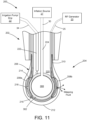
- FIG. 11 is side view, partly in section, of another embodiment of an ablation device 200 consistent with the present disclosure, including an expandable distal applicator tip assembly 204 extending from a distal end of a handle 202, consistent with the present disclosure.
- the distal applicator tip assembly 204 includes a nonconductive tip 206 extending from a distal end of the handle 202 and an electrode array comprising a plurality of independent conductive wires 208 extending along an external surface of the nonconductive tip 206.
- the tip assembly 204 is flexible and generally formed from a low durometer material.
- the nonconductive tip 206 and electrode array are generally flexible and configured to transition from a collapsed configuration, in which the tip 206 has a smaller diameter and can be more easily delivered to a target site, to an expanded configuration (e.g., generally spherical) upon a inflation of an inner balloon member.
- the expansion of the tip assembly 204 allows for the tip assembly to conform to the contour of a target tissue, allowing for improved contact and ablation/coagulation performance.
- the nonconductive tip 206 includes a proximal end 210 coupled to the distal end of the handle 202 and a distal end 212.
- the nonconductive tip 206 includes a flexible body configured to transition from a collapsed configuration to an expanded configuration upon inflation of an inner balloon member. Upon deflation of the inner balloon member, the nonconductive tip 206 is configured to transition back to the collapsed configuration.
- the nonconductive tip 206 may include an elastomeric or shape memory material. As shown in FIGS. 3 and 4 , the nonconductive tip 206 has a generally spherical shape when in the expanded configuration.
- the nonconductive tip 206 Upon application of a force (e.g., pressing of the tip 206 against a target site), the nonconductive tip 206 is configured to flex and transition into a deformed state, where portions of the nonconductive tip 206 can become deformed such that nonconductive tip assumes a compressed shape.
- a force e.g., pressing of the tip 206 against a target site
- the nonconductive tip 206 includes plurality of proximal ports 214 and distal ports 216 in communication with at least a lumen of the handle 202.
- the proximal ports 214 and distal ports 216 generally serve as openings through which conductive wires 208 may pass.
- each of the plurality of wires 208 passes through an associated one of the proximal ports and through a corresponding one of the distal ports.
- the number of proximal ports 214 and distal ports 216 may generally be equal to the number of conductive wires 208, such that each conductive wire 208 can extend through a different distal port 216, which allows the conductive wires 208 to remain electrically isolated from one another.
- one or more conductive wires can extend through the same distal port 216.
- the nonconductive tip 206 may further include one or more medial ports 218 configured to allow passage of fluid from the within the nonconductive tip 206 to an external surface of the nonconductive tip 206, as will be described in greater detail herein.
- each conductive wire 208 can extend along an external surface of the nonconductive tip 206.
- the length of the conductive wire 208 extending along the external surface is at least 20% (e.g., at least, 50%, 60%, 75%, 85%, 90%, or 99%) of the length of the nonconductive tip 206.
- the conductive wire 208 can then re-enter the nonconductive tip 206 through a corresponding proximal port 214. For example, as shown in FIG.
- conductive wire 208a passes through distal port 216, extends along a length of the external surface of the nonconductive tip 206, and passes through an associated proximal port 214 and into a cavity or interior chamber of the nonconductive tip 206, while conductive wire 208b is electrically isolated from conductive wire 208b in that it passes through its own associated proximal and distal ports.
- the wires 208 are configured to receive energy in the form of electrical current from the RF generator 20 and emit RF energy in response.
- the conductive wires 208 can be formed of any suitable conductive material (e.g., a metal such as stainless steel, nitinol, or aluminum).
- one or more of the conductive wires 208 can be electrically isolated from one or more of the remaining conductive wires, such that the electrical isolation enables various operation modes for the device 200.
- electrical current may be supplied to one or more conductive wires in a bipolar mode, a unipolar mode, or a combination bipolar and unipolar mode.
- unipolar mode ablation energy is delivered between one or more conductive wires of the electrode array a return electrode, for example.
- bipolar mode energy is delivered between at least two of the conductive wires, while at least one conductive wire remains neutral.
- at least, one conductive wire functions as a grounded conductive wire (e.g., electrode) by not delivering energy over at least one conductive wire.
- each conductive wire 208 in the electrode array is electrically independent, each conductive wire 208 can be connected in a fashion that allows for impedance measurements using bipolar impedance measurement circuits.
- the conductive wires can be configured in such a fashion that tetrapolar or guarded tetrapolar electrode configurations can be used.
- one pair of conductive wires could function as the current driver and the current return, while another pair of conductive wires could function as a voltage measurement pair.
- a dispersive ground pad can function as current return and voltage references. Their placement dictate the current paths and thus having multiple references can also benefit by providing additional paths for determining the ablation status of the tissue.
- the ablation device 200 is configured to provide RF ablation via a virtual electrode arrangement.
- energy conducted by one or more of the wires 208 is carried by the fluid weeping from the nonconductive tip 206, thereby creating a virtual electrode.
- the nonconductive tip 206 includes an interior chamber 220 retaining at least an inner balloon member 300 therein, which may essentially act as a spacing member, and a hydrophilic insert 302 surrounding a inner balloon member 300.
- the handle 202 includes a fluid lumen 222 coupled to the irrigation pump or drip 22 via the fluid line 34 and is configured to receive conductive fluid therefrom.
- the hydrophilic insert 302 is configured receive and evenly distribute the conductive fluid from the fluid lumen 222 within the interior chamber 220 by wicking the saline against gravity.
- the saline within the chamber 220 may be distributed from the hydrophilic insert 302 to an external surface of the tip 206 through the one or more medial ports 218 and/or the other ports (e.g., to the proximal ports 214 and distal ports 216).
- the saline weeping through the medial ports 218 and/or proximal and distal ports 214, 216 to an outer surface of the nonconductive tip 206 is able to carry electrical current from the electrode array, such that energy is transmitted from the electrode array to a target tissue by way of the saline, thereby creating a virtual electrode.
- the handle 202 further includes an inflation lumen 224 configured to be coupled to the inflation source 27 via the connection line 30.
- the inflatable balloon member 300 is in fluid communication with the inflation source 27 via the inflation lumen 30, such that, when the inflation source is activated, the inner balloon member 300 inflates.
- the inner balloon member 300 is shaped and sized so as to maintain the hydrophilic insert 302 in contact with the interior surface of the distal tip wall, and specifically in contact with the one or more ports, such that the hydrophilic insert provides uniformity of saline distribution to one or more of the ports (i.e., at least one of the proximal, distal, and medial ports).
- the inner balloon member can be inflated to transition the distal tip to the expanded configuration, and the electrode array can be activated. Fluid can then be delivered to the interior chamber, specifically collecting in the hydrophilic insert, and the fluid weeping through the ports to the outer surface of the distal portion is able to carry energy from electrode array, thereby creating a virtual electrode. Accordingly, upon the fluid weeping through the ports, a pool or thin film of fluid is formed on the exterior surface of the distal tip and is configured to ablate surrounding tissue via the RF energy carried from the electrode array.
Landscapes
- Health & Medical Sciences (AREA)
- Surgery (AREA)
- Life Sciences & Earth Sciences (AREA)
- Engineering & Computer Science (AREA)
- Nuclear Medicine, Radiotherapy & Molecular Imaging (AREA)
- Public Health (AREA)
- General Health & Medical Sciences (AREA)
- Veterinary Medicine (AREA)
- Animal Behavior & Ethology (AREA)
- Biomedical Technology (AREA)
- Heart & Thoracic Surgery (AREA)
- Medical Informatics (AREA)
- Molecular Biology (AREA)
- Physics & Mathematics (AREA)
- Plasma & Fusion (AREA)
- Otolaryngology (AREA)
- Radiology & Medical Imaging (AREA)
- Pathology (AREA)
- Gynecology & Obstetrics (AREA)
- Oral & Maxillofacial Surgery (AREA)
- Cardiology (AREA)
- Surgical Instruments (AREA)
Description
- The present disclosure relates generally to medical devices for ablating tissue, and, more particularly, to a minimally invasive articulating assembly including a delivery device in the form of a guide sheath configured to be advanced through tortuous anatomy, within a lung, and deliver at least two separate steerable and expandable ablation devices to a target site located at a bifurcated section within the lung (e.g., bronchial airway bifurcation), wherein the expandable ablation devices are configured to be deployed and cooperatively controlled so as to apply compression and/or energy emission to the target tissue for subsequent ablation thereof.
- Ablation therapy is a type of minimally invasive procedure medical professionals (i.e., surgeons) use to destroy abnormal tissue that occurs with many conditions. For example, a doctor might use an ablation procedure to treat a cancerous tumor (i.e., completely destroy cancerous tissue) or to destroy (ablate) a small amount of tissue, such as in the heart so as to prevent and/or treat abnormal heart rhythms. In some instances, ablation therapy may be particularly difficult due to the location of the abnormal tissue to be treated and the degree of preciseness required to avoid ablating adjacent healthy tissue, such as diseases of the lung.
- For example, emphysema is a lung condition that causes shortness of breath. In people with emphysema, the air sacs in the lungs (alveoli) are damaged. Over time, the inner walls of the air sacs weaken and rupture, thereby creating larger air spaces instead of many small ones, which reduces the surface area of the lungs and, in turn, the amount of oxygen that reaches the bloodstream. A currently available solution for patients suffering from emphysema is a surgical procedure called Lung Volume Reduction (LVR) surgery whereby diseased lung is resected and the volume of the lung is reduced. Such a procedure allows healthier lung tissue to expand into the volume previously occupied by the diseased tissue and allows the diaphragm to recover. However, high mortality and morbidity may be associated with this invasive procedure.
- Several minimally invasive investigational therapies exist that aim at improving the quality of life and restoring lung function for patients suffering from emphysema, such as mechanical implants in the form of one-way valve devices, which achieve absorptive atelectasis of a lung (i.e., the collapse of part of the lung) by preventing air from entering diseased portion of the lung, while allowing air and mucous to pass through the device out of the diseased regions. However, such devices may lack effectiveness. In particular, studies have shown that a phenomenon known as collateral ventilation, which is the ventilation of alveolar structure through passages or channels that bypass normal airway and thus prevent complete occlusion, prevents atelectasis. The lack of atelectasis or lung volume reduction drastically reduces the effectiveness of currently known mechanical implants. Other mechanical devices include means of deploying anchors into airways and physically deforming airways by drawing the anchors together via cables. Biological treatments may utilize tissue engineering aimed at causing scarring at specific locations. Unfortunately, it can be difficult to control the scarring and to prevent uncontrolled proliferation of scarring.
-
US2014018788 A1 discloses methods and endovascular catheters for assessing, and treating patients having sympathetically mediated disease, involving augmented peripheral chemoreflex and heightened sympathetic tone by reducing chemosensor input to the nervous system via transmural carotid body ablation. -
US2017119454 A1 discloses an ablation device having a screen sphere configuration for the ablation of marginal tissue surrounding a tissue cavity. The device includes a probe having a nonconductive elongated shaft including at least one lumen therethrough and a nonconductive distal portion extending from the shaft. The nonconductive distal portion includes a plurality distal ports and a plurality of proximal ports in communication with the at least one lumen of the shaft. The device further includes an electrode array including a plurality of independent conductive wires extending through the lumen and positioned along an external surface of the nonconductive distal portion, each of the plurality of wires passes through at least an associated one of the proximal ports and through at least a corresponding one of the distal ports. -
US2016317221 A1 discloses tissue ablation system including an ablation device having a deployable applicator head configured to be delivered to a tissue cavity and ablate marginal tissue surrounding the tissue cavity. The deployable applicator head is configured to be delivered to a tissue cavity while in a collapsed configuration and ablate marginal tissue surrounding the tissue cavity while in an expanded configuration. - According to a first aspect of the invention, there is provided a minimally invasive medical assembly as defined in independent claim 1. According to a second aspect of the invention, there is provided a minimally invasive medical assembly as defined in independent claim 2. Optional and/or preferable features are defined in the dependent claims.
- A first one of the ablation devices is steerable towards a first pathway extending from the bifurcation and a second one of the ablation devices is separately steerable towards a second pathway extending from the bifurcation, such that each of the ablation devices can be positioned on either side of a target tissue proximate the bifurcation. The first and second ablation devices each include a distal applicator tip configured to transition between a delivery configuration, in which the applicator tip is collapsed and is shaped and sized to fit within and pass through a pathway (i.e., bronchial airway), and a deployed configuration, in which the applicator tip is expanded and is shaped and sized in such a manner so as to become lodged or anchored within the pathway and thereby apply at least a degree of compression upon the target tissue, such that the target tissue is generally compressed between the distal applicator tips. One or both of the distal applicator tips further includes an electrode array configured to emit RF energy upon the target tissue for subsequent ablation thereof.
- Accordingly, the assembly of the present invention allows for improved controlled over the ablation of tissue, particularly in normally isolated regions ((i.e., tortuous pathways in the lung), allowing for application of RF energy in a controlled manner with little or no deleterious effect on surrounding healthy tissue or organs. Furthermore, the present invention allows for debulking of diseased tissue almost immediately by way of RF ablation, such that, upon treating the diseased tissue, necrosis of such tissue is immediate and the assembly can be completely removed once the procedure is completed, and thus does not present any issues that may be present with devices requiring implantation for a given period of time.
- Features and advantages of the claimed subject matter will be apparent from the following detailed description of embodiments consistent therewith, which description should be considered with reference to the accompanying drawings, wherein:
-
FIGS. 1A and IB are schematic illustrations of an ablation system consistent with the present disclosure; -
FIG. 2 is a perspective view of one embodiment of a steerable and expandable ablation device compatible with the system ofFIG. 1 A; -
FIGS. 3 A and 3B are enlarged views of a distal applicator tip of the ablation device ofFIG. 2 in greater detail, illustrating transition of the applicator tip between a delivery configuration (FIG. 3A ) and a deployed configuration (FIG. 3B ); -
FIG. 4 is a side view of an articulating assembly consistent with the present disclosure, illustrating a pair of steerable and expandable ablation devices extended from an delivery device, wherein the distal tip of the first ablation device is in the delivery configuration and the distal tip of the second ablation device is in the deployed configuration; -
FIGS. 5A and 5B illustrate positioning and movement of the articulating assembly through tortuous pathways within the bronchial airways of a lung, specifically illustrating the steerable nature of at least one ablation device positioned with the delivery device; -
FIG. 5C illustrates positioning of the distal applicator tips of the first and second ablation devices, specifically illustrating independent movement of each applicator tip into a respective pathway extending from a bronchial airway bifurcation and further positioned on sides of a target tissue to be ablated; -
FIG. 5D illustrates deployment of the distal applicator tips of the first and second ablation devices, including advancement of the tips from the respective guide sheaths of the corresponding ablation device, and further illustrates the drawing of the distal applicator tips towards one another based on retraction of a pull wire or tether coupled to both of the ablation devices; -
FIG. 5E illustrates transitioning of the distal applicator tips from the delivery configuration to the expanded configuration, expanding in diameter and becoming lodged or anchored within the respective pathways of the bronchial airway and further compressing the target tissue between one another; -
FIG. 5F illustrates the ablation of the target tissue based on the emission of radiofrequency (RF) energy from the distal applicator tips andFIG. 5G illustrates the ablated target tissue; -
FIGS. 6A ,6B ,6C , and6D illustrate an articulating assembly having a tetherless designed (i.e., no pull wire or tether coupled to either of the first and second ablation devices); -
FIG. 7 is a perspective view of one embodiment of a distal applicator tip consistent with the present disclosure; -
FIG. 8 is an exploded view of the distal application tip ofFIG. 7 ; -
FIG. 9 is a perspective view, partly in section, of the distal applicator tip ofFIG. 7 ;FIGS. 10A and 10B are sectional views of a portion of the distal applicator tip ofFIG. 9 illustrating the arrangement of components relative to one another; and -
FIG. 11 is side view, partly in section, of another embodiment of a distal applicator tip consistent with the present disclosure. - For a thorough understanding of the present disclosure, reference should be made to the following detailed description, including the appended claims, in connection with the above-described drawings. Although the present disclosure is described in connection with exemplary embodiments, the disclosure is not intended to be limited to the specific forms set forth herein. It is understood that various omissions and substitutions of equivalents are contemplated as circumstances may suggest or render expedient.
- By way of overview, the present disclosure is generally directed to a minimally invasive articulating assembly configured to be delivered to a surgical site within a patient and further configured to be advanced through a tortuous anatomy to reach a target tissue and subsequently provide ablation treatment to the target tissue. In particular, the articulating assembly includes a delivery device in the form of a scope or other access device configured to provide access to a target site within a patient. The delivery device has an outer guide sheath configured to be advanced through the tortuous anatomy, particularly within a lung, and subsequently deliver at least two separately deployable and expandable ablation devices to the target site located at a bifurcated section of the lung (i.e., at a bronchial airway bifurcation) for ablation of the target tissue, which may include diseased lung tissue, including, but not limited to, a cancerous tumor or emphysema-related damaged tissue.
- A first one of the ablation devices is steerable towards a first pathway extending from the bifurcation and a second one of the ablation devices is separately steerable towards a second pathway extending from the bifurcation, such that each of the ablation devices can be positioned on either side of a target tissue proximate the bifurcation. The first and second ablation devices each include a distal applicator tip configured to transition between a delivery configuration, in which the applicator tip is collapsed and is shaped and sized to fit within and pass through a pathway (i.e., bronchial airway), and a deployed configuration, in which the applicator tip is expanded and is shaped and sized in such a manner so as to become lodged or anchored within the pathway and thereby apply at least a degree of compression upon the target tissue, such that the target tissue is generally compressed between the distal applicator tips. One or both of the distal applicator tips further includes an electrode array configured to emit RF energy upon the target tissue for subsequent ablation thereof.
- Accordingly, the assembly of the present invention allows for improved controlled over the ablation of tissue, particularly in normally isolated regions ((i.e., tortuous pathways in the lung), allowing for application of RF energy in a controlled manner with little or no deleterious effect on surrounding healthy tissue or organs. Furthermore, the present invention allows for debulking of diseased tissue almost immediately by way of RF ablation, such that, upon treating the diseased tissue, necrosis of such tissue is immediate and the assembly can be completely removed once the procedure is completed, and thus does not present any issues that may be present with devices requiring implantation for a given period of time.
- For ease of description and explanation, the following description focuses on the use of the articulating assembly within the tortuous passageways of the lung of a patient. However, it should be noted that the present invention can be used in any other organs which may include tortuous pathways, such as the heart or the vascular system, and which may further include bifurcations.
-
FIGS. 1A and 1B are schematic illustrations of anablation system 10 for providing ablation of diseased tissue within apatient 12. Theablation system 10 generally includes an articulatingassembly 14, including adelivery device 15, which may be in the form of a scope or other access device configured to provide access to a target site within thepatient 12. Thedelivery device 15 is configured to be advanced through the tortuous anatomy, particularly within a lung, and subsequently deliver at least two separately deployable andexpandable ablation devices assembly 14, specifically each of the first andsecond ablation devices controller 18, anablation RF generator 20, and an irrigation pump ordrip 22. - As will be described in greater detail herein, each of the
ablation devices ablation controller 18 may be used to control the emission of energy from the electrode array of a distal tip of anablation device 16 to result in ablation, as well as control parameters of the ablation (i.e., elapsed time, total energy output, specific energy output pattern, etc.). - In some embodiments, each
ablation device 16 may be further configurd to provide RF ablation via a virtual electrode arrangement, which includes distribution of a fluid along an exterior surface of the distal tip and, upon activation of the electrode array, the fluid may carry, or otherwise promote, energy emitted from the electrode array to the surrounding tissue. In particular, the distal tip of an ablation device may include a plurality of ports or apertures configured to allow the fluid to pass therethrough, or weep, from an interior of the distal tip to an external surface of the distal tip. Accordingly, the irrigation pump ordrip 22 may provide the conductive fluid (e.g., saline) to the distal tip of each ablation device. - As will be described in greater detail herein, during an ablation treatment, the
RF generator 20 may generally provide RF energy (e.g., electrical energy in the radiofrequency (RF) range (e.g., 350-800 kHz)) to an electrode array of one of theablation devices 16, as controlled by theablation controller 18. At the same time, saline may also be released from the irrigation pump ordrip 22 the distal tip of theablation device 16. - The
ablation system 10 may further include animaging modality 24. For example, during a procedure, theimaging modality 24 may provide an operator (e.g., surgeon) with a visual depiction of distal end of thedelivery device 15 during advancement towards the target site and may further provide visual depiction of theablation devices imaging modality 24 may be configured to receive sensing input from thedelivery device 15, theablation devices scope 15 and/orablation devices imaging modality 24 may provide a medical imaging procedure, including, but not limited to, ultrasound (US), wavelength detection, X-ray-based imaging, illumination, computed tomography (CT), radiography, and fluoroscopy, or a combination thereof, such that, when viewed under such a medical imaging procedure provided by theimaging modality 24, the visibility of the target site is enhanced and a surgeon can better maneuver thescope 15 and each of the first andsecond ablation devices -
FIG. 2 is a perspective view of one embodiment of a steerable andexpandable ablation device 16 compatible with the articulatingassembly 14. As shown, theablation device 16 generally includes aguide sheath 26 sized or shaped to fit within thedelivery device 15. Theablation device 16 further includes adistal applicator tip 28 configured to extend from a distal end of theguide sheath 26. Thetip 28 generally includes a flexible body configured to have a collapsed configuration and entirely fit within the lumen of theguide sheath 26, such that, upon advancing theguide sheath 26 to the target site, thetip 28 can be extended from the distal end of theguide sheath 26 and the surgeon can control transitioning of thetip 28 from a delivery configuration to a deployed configuration. When in the delivery configuration (as shown inFIG. 3A ), thetip 28 is collapsed and is shaped and sized to fit within and pass through a pathway (i.e., bronchial airway). When in the deployed configuration (as shown inFIG. 3B ), thetip 28 is expanded in response to inflation of thetip 28. For example, in some embodiments, thetip 28 may include an inner balloon (not shown) configured to receive a fluid or gas via aline 30 coupled to a source controllable via a controller, such as avalve 32 or the like. Upon inflation of the inner balloon, thetip 28 may correspondingly expand to assume the deployed configuration. Thetip 28 is further coupled to the irrigation pump ordrip 22 via afluid line 34, in which the flow of conductive fluid from the irrigation pump ordrip 22 to thetip 28 may be controlled manually via avalve 36 or the like. Accordingly, thetip 28 may include a design similar to the ablation device design described inU.S. Application No. 15/142,616, filed April 29, 2016 2016/0317221 ). - As will be described in greater detail herein, the
ablation device 16 is steerable by way of a pull wire or tether that is anchored to a distal end of theguide sheath 26, thereby allowing maneuverability of thetip 28 when advancing theablation device 16 through bronchial airways. The pull wire or tether may be housed within asheath 38 housing the pull wire or tether, for example. As generally understood, application of a pulling force upon the pull wire will generally result in a corresponding deflection of the distal end of theguide sheath 26, thereby allowing for the ablation device to be maneuvered past bifurcations or other obstructions. - As previously described herein, the
ablation device 16 may further include sensors or the like to assist in providing visualization of the device to a surgeon during a procedure. Thus, in some embodiments, the ablation device may include a sensor, including, for example, an ultrasound transducer positioned along theguide sheath 26 adjacent to a distal end thereof or placed upon thetip 28 body, wherein a line providing signal from the sensor may be housed within asheath 40. Furthermore, the electrical line (not shown) coupling theRF generator 20 to an electrode array on thetip 28 may further be housed within a separate sheath (not shown). - As shown in
FIGS. 3A and 3B , thetip 28 includes an electrode array is composed of a plurality of conductive members (e.g., conductive wires) 42. In some embodiments, each of the plurality ofconductive wires 42, or one or more sets of a combination ofconductive wires 42, is configured to independently receive an electrical current from theRF generator 20 and independently conduct energy, the energy including RF energy. This allows energy to be selectively delivered to a designated conductive wire or combination of conductive wires. This design also enables theablation device 16 to function in a bipolar mode because a first conductive wire (or combination of conductive wires) can deliver energy to the surrounding tissue through its electrical connection with the RF generator while a second conductive wire (or combination of conductive wiress) can function as a ground or neutral conductive member. - In some embodiments, the
ablation device 16 is configurd to provide RF ablation via a virtual electrode arrangement, which includes distribution of a fluid along an exterior surface of thedistal tip 28 and, upon activation of the electrode array, the fluid may carry, or otherwise promote, energy emitted from the electrode array to the surrounding tissue. For example, as previously described, thetip 28 includes an interior chamber configured to receive the conductive fluid thereoin from the fluid source. Thetip 28 body includes a plurality of ports, ports, orapertures 44 configured to allow the fluid to pass therethrough, or weep, from the interior chamber to an external surface of thetip 28. Accordingly, upon positioning thetip 28 at a target site and subsequently deploying the tip 28 (i.e., transitioning thetip 28 from the delivery configuration to the deployed configuration shown inFIG. 3B ) the electrode array can be activated and fluid can be delivered to thetip 28. The fluid weeping through theports 44 to the outer surface of thetip 28 is able to carry energy from electrode array, thereby creating a virtual electrode. Accordingly, upon the fluid weeping through the ports, a pool or thin film of fluid is formed on the exterior surface of thetip 28 and is configured to ablate surrounding tissue via the RF energy carried from the electrode array. -
FIG. 4 is a side view of an articulatingassembly 14 illustrating a pair of steerable andexpandable ablation devices delivery device 15. It should be noted that thedelivery device 15 may include a scope, including, but not limited to, an endoscope, laparoscope, catheter, trocar, or other delivery device. For most applications described herein, thedelivery device 15 is an endoscope. As shown, thedistal tip 28a of thefirst ablation device 16a is in the delivery configuration (i.e., collapsed shape) and thedistal tip 28b of thesecond ablation device 16b is in the deployed configuration (i.e., expanded shape), illustrating that theablation devices - As shown, the
second ablation device 16b may be coupled to thefirst ablation device 16a via thepull wire 46. For example, as shown, thepull wire 46 is directly secured at one end to the distal end of theguide sheath 26a of thefirst ablation device 16a at ananchor point 48. Accordingly, upon application of a force upon thepull wire 46, the distal end of theguide sheath 26a corresponding deflects. Thepull wire 46 is further coupled to thesecond ablation device 16b by way of a loop or hook 50 positioned at a distal end of theguide sheath 26b of thesecond ablation device 16b through which thepull wire 46 passes. Accordingly, a pulling force upon thepull wire 46 generally results drawing of the distal ends of theguide sheaths second ablation devices tips tips 28 are in the deployed configurations on opposing sides of a target tissue, a surgeon need only apply a pulling force upon thepull wire 46, which results in drawing of thetips tips tips -
FIGS. 5A and 5B illustrate the positioning and movement of the articulatingassembly 14 through tortuous pathways within the bronchial airways of a lung. As previously described, the delivery device may be in the form of a scope and is configured to carry at least twoablation devices delivery device 15 while advancing theassembly 15 through the bronchial passages of the lung towards the target site which includes diseased tissue, which may include, but is not limited to, a cancerous tumor or emphysema-related damaged tissue. Use of theimaging modality 24 allows for the surgeon to view theassembly 14 during advancement through tortuous anatomy, wherein, upon encountering obstructions, the surgeon can maneuver the scope to continue advancement. - Referring to
FIG. 5C , upon reaching the target site, which may be located at a bifurcated section of the lung (i.e., at a bronchial airway bifurcation), the surgeon can then begin delivery of theablation devices first ablation device 16a is steerable towards a first pathway extending from the bifurcation and thesecond ablation device 16b is separately steerable towards a second pathway extending from the bifurcation, such the first andsecond ablation devices -
FIG. 5D illustrates deployment of thedistal applicator tips second ablation devices tips respective guide sheaths pull wire 46, which, as previously described, results in drawing of thetips FIG. 5E illustrates transitioning of thedistal applicator tips second tips FIG. 5F , ablation of the target tissue occurs based on the emission of radiofrequency (RF) energy from thedistal applicator tips FIG. 5G illustrates the ablated target tissue. It should be noted that, in some embodiments, it may be desirable to activate RF emission from only one of the tips, resulting in a directed ablation pattern (i.e., ablation on one side of the target tissue) while the other tip remains in an inactive state and is relied upon as a backstop for maintaining the other active tip in position during ablation. -
FIG. 6A-6D illustrate an articulating assembly having a tetherless designed (i.e., the assembly does not include a pull wire or tether coupled to either of the first and second ablation devices).FIG. 6A illustrates positioning of the distal applicator tips of the first and second ablation devices, specifically illustrating independent movement of each applicator tip into a respective pathway extending from a bronchial airway bifurcation and further positioned on sides of a target tissue to be ablated. -
FIG. 6B illustrates deployment of the distal applicator tips of the first and second ablation devices, including advancement of the tips from the respective guide sheaths of the corresponding ablation device.FIG. 6C illustrates the advancement of the outer guide sheath of the delivery device towards the applicator tips, thereby resulting in the drawing of the distal applicator tips towards one another; and -
FIG. 6D illustrates transitioning of the distal applicator tips from the delivery configuration to the expanded configuration, expanding in diameter and becoming lodged or anchored within the respective pathways of the bronchial airway and further compressing the target tissue between one another and subsequent ablation of the target tissue based on the emission of radiofrequency (RF) energy from the distal applicator tips. - Accordingly, the assembly of the present invention allows for improved controlled over the ablation of tissue, particularly in normally isolated regions ((i.e., tortuous pathways in the lung), allowing for application of RF energy in a controlled manner with little or no deleterious effect on surrounding healthy tissue or organs. Furthermore, the present invention allows for debulking of diseased tissue almost immediately by way of RF ablation, such that, upon treating the diseased tissue, necrosis of such tissue is immediate and the assembly can be completely removed once the procedure is completed, and thus does not present any issues that may be present with devices requiring implantation for a given period of time.
-
FIG. 7 is a perspective view of one embodiment of anablation device 100 consistent with the present disclosure, including an expandabledistal applicator tip 104 extending from a distal end of ahandle 102, consistent with the present disclosure.FIG. 8 is an exploded view of theablation device 100, specifically thedistal application tip 104 ofFIG. 7 . As shown, theapplicator tip 104 includes a multiple-balloon design. For example, theapplicator tip 104 includes aninner balloon 106 coupled to a first fluid source via afirst fluid line 30 and configured to inflate into an expanded configuration in response to the delivery of fluid (e.g., saline, air, etc.) thereto. Theapplicator tip 104 further includes anouter balloon 108 surrounding theinner balloon 106 and configured to correspondingly expand or collapse in response to expansion or collapse of theinner balloon 106. - The
inner balloon 106 may include an irregularouter surface 112, which may include a plurality of bumps, ridges, or other features, configured to maintain separation between the outer surface of theinner balloon 106 and an interior surface of theouter balloon 108, thereby ensuring that a chamber is maintained between the inner and outer balloons. Theouter balloon 108 may be coupled to a second fluid source (or the first fluid source) via asecond fluid line 34. Theouter balloon 108 may further include a plurality of perforations, holes, orports 114 so as to allow fluid from the second fluid source to pass therethrough, or weep, from theouter balloon 108. The perforations may be sized, shaped, and/or arranged in such a pattern so as to allow a volume of fluid to pass from the chamber to an exterior surface of the outer balloon at a controlled rate. - The
applicator tip 104 further includes one or more conductive elements, generally resembling electrically conductive wires ortines 110, positioned within the chamber area between theinner balloon 106 andouter balloon 108. Theconductive elements 110 are coupled to theRF generator 20 via anelectrical line 25, and configured to conduct electrical current to be carried by the fluid within the chamber from the interior surface to the exterior surface of theouter balloon 108 for ablation of a target tissue, as will be described in greater detail herein. It should be noted that in one embodiment, the plurality ofconductive wires 110 may be electrically isolated and independent from one another. This design allows for each conductive wire to receive energy in the form of electrical current from a source (e.g., RF generator) and emit RF energy in response. The system may include adevice controller 18, for example, configured to selectively control the supply of electrical current to each of theconductive wires 110. -
FIG. 9 is a perspective view, partly in section, of thedistal applicator tip 104.FIGS. 10A and 10B are sectional views of a portion of thedistal applicator tip 104 illustrating the arrangement of components relative to one another. - As shown in
FIG. 9 , the inner and outer balloons include achamber 118 defined there between. In particular, the plurality of bumps orridges 112 arranged on an outer surface of theinner balloon 106 are configured to maintain separation between the outer surface of theinner balloon 202 and an interior surface of theouter balloon 108, thereby ensuring thechamber 118 is maintained. - Once positioned within the target site, a first fluid may be delivered to a
lumen 116 of theinner balloon 106, so as to inflate theinner balloon 106 into an expanded configuration, at which point, theouter balloon 108 further expands. A second fluid may then be delivered to theouter balloon 108 such that the second fluid flows within thechamber 118 between the inner andouter balloons outer balloon 108 via theports 114. Upon activating delivery of RF energy from theconductive elements 110, the RF energy is transmitted from theconductive elements 110 to the outer surface of theouter balloon 108 by way of the fluid weeping from theperforations 114, thereby creating a virtual electrode. For example, the fluid within thechamber 118 and weeping through theperforations 114 on theouter balloon 108 is a conductive fluid (e.g., saline) and thus able to carry electrical current from the activeconductive elements 110. Accordingly, upon the fluid weeping through theperforations 114, a pool or thin film of fluid is formed on the exterior surface of theouter balloon 108 and is configured to ablate surrounding tissue via the electrical current carried from the activeconductive elements 110. Accordingly, ablation via RF energy is able to occur on the exterior surface of theouter balloon 108 in a controlled manner and does not require direct contact between tissue and theconductive elements 110. - This embodiment is particularly advantageous in that the dual-balloon design does not require a syringe pump, and can be supplied with gravity-fed
fluid source 22. In addition, the volume of fluid required within the chamber is significantly less (when compared to a single balloon design), thus less wattage is required to achieve RF ablation. Another advantage of the dual-balloon design ofdistal tip 104 is that it is not limited to placement within tissue cavities. Rather, when in a collapsed state, thedistal tip 104 is shaped and/or sized to fit through working channels of scopes or other access devices, for example, and thus be used for ablation in a plurality of locations within the human body. - It should be further noted that a
device 100 of the present disclosure, including thedistal tip 104, may further be equipped with feedback capabilities. For example, while in a deflated, collapsed configuration, and prior to saline flow, thetip 104 may be used for the collection of initial data (e.g., temperature and conductivity measurements (impedance measurements) from one or more of theconductive elements 110. Then, upon carrying out the ablation procedure, after certain time ablating, saline flow may be stopped (controlled via controller 18), and subsequent impedance measurements may be taken. The collection of data prior and during an ablation procedure may be processed by thecontroller 18 so as to provide an estimation of the state of the tissue during an RF ablation procedure, thereby providing an operator (e.g., surgeon) with an accurate indication success of the procedure. -
FIG. 11 is side view, partly in section, of another embodiment of anablation device 200 consistent with the present disclosure, including an expandable distalapplicator tip assembly 204 extending from a distal end of ahandle 202, consistent with the present disclosure. The distalapplicator tip assembly 204 includes anonconductive tip 206 extending from a distal end of thehandle 202 and an electrode array comprising a plurality of independent conductive wires 208 extending along an external surface of thenonconductive tip 206. As will be described in greater detail herein, thetip assembly 204 is flexible and generally formed from a low durometer material. More specifically, thenonconductive tip 206 and electrode array are generally flexible and configured to transition from a collapsed configuration, in which thetip 206 has a smaller diameter and can be more easily delivered to a target site, to an expanded configuration (e.g., generally spherical) upon a inflation of an inner balloon member. The expansion of thetip assembly 204 allows for the tip assembly to conform to the contour of a target tissue, allowing for improved contact and ablation/coagulation performance. - As shown, the
nonconductive tip 206 includes aproximal end 210 coupled to the distal end of thehandle 202 and adistal end 212. Thenonconductive tip 206 includes a flexible body configured to transition from a collapsed configuration to an expanded configuration upon inflation of an inner balloon member. Upon deflation of the inner balloon member, thenonconductive tip 206 is configured to transition back to the collapsed configuration. Accordingly, thenonconductive tip 206 may include an elastomeric or shape memory material. As shown inFIGS. 3 and4 , thenonconductive tip 206 has a generally spherical shape when in the expanded configuration. Upon application of a force (e.g., pressing of thetip 206 against a target site), thenonconductive tip 206 is configured to flex and transition into a deformed state, where portions of thenonconductive tip 206 can become deformed such that nonconductive tip assumes a compressed shape. - The
nonconductive tip 206 includes plurality ofproximal ports 214 anddistal ports 216 in communication with at least a lumen of thehandle 202. Theproximal ports 214 anddistal ports 216 generally serve as openings through which conductive wires 208 may pass. For example, each of the plurality of wires 208 passes through an associated one of the proximal ports and through a corresponding one of the distal ports. Accordingly, the number ofproximal ports 214 anddistal ports 216 may generally be equal to the number of conductive wires 208, such that each conductive wire 208 can extend through a differentdistal port 216, which allows the conductive wires 208 to remain electrically isolated from one another. In other examples, one or more conductive wires can extend through the samedistal port 216. Thenonconductive tip 206 may further include one or moremedial ports 218 configured to allow passage of fluid from the within thenonconductive tip 206 to an external surface of thenonconductive tip 206, as will be described in greater detail herein. - Upon passing through a
distal port 216, each conductive wire 208 can extend along an external surface of thenonconductive tip 206. In some examples, the length of the conductive wire 208 extending along the external surface is at least 20% (e.g., at least, 50%, 60%, 75%, 85%, 90%, or 99%) of the length of thenonconductive tip 206. The conductive wire 208 can then re-enter thenonconductive tip 206 through a correspondingproximal port 214. For example, as shown inFIG. 11 ,conductive wire 208a passes throughdistal port 216, extends along a length of the external surface of thenonconductive tip 206, and passes through an associatedproximal port 214 and into a cavity or interior chamber of thenonconductive tip 206, whileconductive wire 208b is electrically isolated fromconductive wire 208b in that it passes through its own associated proximal and distal ports. The wires 208 are configured to receive energy in the form of electrical current from theRF generator 20 and emit RF energy in response. The conductive wires 208 can be formed of any suitable conductive material (e.g., a metal such as stainless steel, nitinol, or aluminum). - As shown, one or more of the conductive wires 208 can be electrically isolated from one or more of the remaining conductive wires, such that the electrical isolation enables various operation modes for the
device 200. For example, electrical current may be supplied to one or more conductive wires in a bipolar mode, a unipolar mode, or a combination bipolar and unipolar mode. In the unipolar mode, ablation energy is delivered between one or more conductive wires of the electrode array a return electrode, for example. In bipolar mode, energy is delivered between at least two of the conductive wires, while at least one conductive wire remains neutral. In other words, at least, one conductive wire functions as a grounded conductive wire (e.g., electrode) by not delivering energy over at least one conductive wire. - Since each conductive wire 208 in the electrode array is electrically independent, each conductive wire 208 can be connected in a fashion that allows for impedance measurements using bipolar impedance measurement circuits. For example, the conductive wires can be configured in such a fashion that tetrapolar or guarded tetrapolar electrode configurations can be used. For instance, one pair of conductive wires could function as the current driver and the current return, while another pair of conductive wires could function as a voltage measurement pair. Accordingly, a dispersive ground pad can function as current return and voltage references. Their placement dictate the current paths and thus having multiple references can also benefit by providing additional paths for determining the ablation status of the tissue.
- As previously described, the
ablation device 200 is configured to provide RF ablation via a virtual electrode arrangement. In particular, energy conducted by one or more of the wires 208 is carried by the fluid weeping from thenonconductive tip 206, thereby creating a virtual electrode. For example, thenonconductive tip 206 includes aninterior chamber 220 retaining at least aninner balloon member 300 therein, which may essentially act as a spacing member, and ahydrophilic insert 302 surrounding ainner balloon member 300. As shown, thehandle 202 includes afluid lumen 222 coupled to the irrigation pump ordrip 22 via thefluid line 34 and is configured to receive conductive fluid therefrom. Thehydrophilic insert 302 is configured receive and evenly distribute the conductive fluid from thefluid lumen 222 within theinterior chamber 220 by wicking the saline against gravity. The saline within thechamber 220 may be distributed from thehydrophilic insert 302 to an external surface of thetip 206 through the one or moremedial ports 218 and/or the other ports (e.g., to theproximal ports 214 and distal ports 216). The saline weeping through themedial ports 218 and/or proximal anddistal ports nonconductive tip 206 is able to carry electrical current from the electrode array, such that energy is transmitted from the electrode array to a target tissue by way of the saline, thereby creating a virtual electrode. - The
handle 202 further includes aninflation lumen 224 configured to be coupled to theinflation source 27 via theconnection line 30. Accordingly, theinflatable balloon member 300 is in fluid communication with theinflation source 27 via theinflation lumen 30, such that, when the inflation source is activated, theinner balloon member 300 inflates. Upon inflation, theinner balloon member 300 is shaped and sized so as to maintain thehydrophilic insert 302 in contact with the interior surface of the distal tip wall, and specifically in contact with the one or more ports, such that the hydrophilic insert provides uniformity of saline distribution to one or more of the ports (i.e., at least one of the proximal, distal, and medial ports). Accordingly, upon positioning the distal tip within a target site, the inner balloon member can be inflated to transition the distal tip to the expanded configuration, and the electrode array can be activated. Fluid can then be delivered to the interior chamber, specifically collecting in the hydrophilic insert, and the fluid weeping through the ports to the outer surface of the distal portion is able to carry energy from electrode array, thereby creating a virtual electrode. Accordingly, upon the fluid weeping through the ports, a pool or thin film of fluid is formed on the exterior surface of the distal tip and is configured to ablate surrounding tissue via the RF energy carried from the electrode array. - Reference throughout this specification to "one embodiment" or "an embodiment" means that a particular feature, structure, or characteristic described in connection with the embodiment is included in at least one embodiment. Thus, appearances of the phrases "in one embodiment" or "in an embodiment" in various places throughout this specification are not necessarily all referring to the same embodiment. Furthermore, the particular features, structures, or characteristics may be combined in any suitable manner in one or more embodiments.
- The terms and expressions which have been employed herein are used as terms of description and not of limitation, and there is no intention, in the use of such terms and expressions, of excluding any equivalents of the features shown and described (or portions thereof), and it is recognized that various modifications are possible within the scope of the claims.
Claims (13)
- A minimally invasive medical assembly (16) for ablating tissue, the assembly comprising:a delivery device (15) configured to provide access to a target site within a hollow body of a patient through the tortuous anatomy within a lung, the delivery device (15) comprising a working channel (26) for delivering a pair of individually deliverable ablation devices (16a, 16b) to the target site;wherein each of the pair of individually deliverable ablation devices (16a, 16b) comprises:a nonconductive, expandable distal applicator tip (28) defining an interior chamber and also defining a plurality of ports (44), at least one of the plurality of ports (44) configured to allow passage of a conductive fluid from the interior chamber to an exterior surface of the distal applicator tip (28);an inflatable member disposed within the interior chamber of the distal applicator tip (28), the inflatable member configured to transition from a collapsed configuration to an expanded configuration and cause the distal applicator tip (28) to correspondingly transition from a collapsed configuration to an expanded spherical shape; anda conductive wire (42) disposed along at least a portion of an exterior surface of the distal applicator tip (28) and configured to conduct energy to be carried by a conductive fluid passing through one or more of the plurality of ports (44);wherein the pair of ablation devices (16a, 16b) are coupled to one another by way of a pull wire (46), and wherein upon application of a pulling force upon the pull wire (46), at least the applicator tips (28) of the ablation devices (16a, 16b) are configured to correspondingly move relative to one another.
- A minimally invasive medical assembly (100) for ablating tissue, the assembly comprising:a delivery device configured to provide access to a target site within a hollow body of a patient through the tortuous anatomy within a lung, the delivery device comprising a working channel for delivering a pair of individually deliverable ablation devices to the target site;wherein each of the pair of individually deliverable ablation devices comprises:
a handle (102); andan expandable assembly extending from the handle, the expandable assembly comprising:an inner expandable member (106) configured to transition from a collapsed configuration to an expanded spherical shape, the inner expandable member (106) comprising an exterior surface (202) including a plurality of ridges (112) defined thereon;an outer expandable member (108) configured to correspondingly transition from a collapsed configuration to an expanded spherical shape in response to expansion of the inner expandable member (106), the outer expandable member (108) comprising a plurality of chambers (118), each chamber (118) is defined between an interior surface of the outer expandable member (108) and the exterior surface (202) of the inner expandable member (106) and a pair of adjacent ridges (112), the outer expandable member further defining a plurality of ports (114), at least one of the plurality of ports (114) configured to allow passage of a conductive fluid from the chambers (118) to an exterior surface of the outer expandable member (108); anda conductive wire (110) disposed within one of the chambers and configured to conduct energy to be carried by a conductive fluid passing through one or more of the plurality of ports (114)wherein the pair of ablation devices (16a, 16b) are coupled to one another by way of a pull wire (46), and wherein upon application of a pulling force upon the pull wire (46), at least the applicator tips (28) of the ablation devices (16a, 16b) are configured to correspondingly move relative to one another. - The assembly (16) of claim 1, wherein each of the pair of individually deliverable ablation devices (16a, 16b) further comprises a handle including a lumen for receiving the conductive fluid, wherein the lumen is in fluid communication with the interior chamber of the distal applicator tip (28).
- The assembly of claim 2, wherein the conductive wire (110) is one of a plurality of conductive wires (110), each of the plurality of conductive wires (110) is disposed within a separate one of the chambers (118).
- The assembly (16) of claim 1, wherein, upon receipt of an electric current, the conductive wire (42) is configured to conduct radiofrequency (RF) energy to be carried by the conductive fluid passing through one or more of the plurality of ports (44) for ablation of a tissue; or
the assembly of claim 4, wherein, upon receipt of an electric current, each of the plurality of conductive wires (110) is configured to conduct radio frequency (RF) energy to be carried by the conductive fluid passing through one or more of the plurality of ports (114) for ablation of a tissue. - The assembly (16) of claim 1, wherein the plurality of ports (44) comprises one or more medial ports for allowing passage of the conductive fluid.
- The assembly (16) of claim 1, wherein the conductive wire (42) is substantially aligned with at least one of the plurality of ports (44); or
the assembly (100) of claim 5 as it depends from claim 2 wherein each of the plurality of conductive wires (110) is substantially aligned with one of the plurality of ports (114). - The assembly (16) of claim 1, wherein the plurality of ports (44) comprises a plurality of proximal ports and distal ports, wherein the conductive wire (42) passes through at least one of the proximal ports and through a corresponding one of the distal ports such that a portion of the conductive wire (42) has a length that extends along the exterior surface of the distal portion between the corresponding proximal and distal ports.
- The assembly (16) of claim 8, wherein (i) the conductive wire (42) is one of a plurality of conductive wires (42), each of the plurality of conductive wires (42) is disposed along at least a portion of the exterior surface of the distal applicator tip (28) and;
optionally or preferably (ii)
wherein each of the plurality of conductive wires (42) passes through at least one of the proximal ports and through a corresponding one of the distal ports, wherein each of the plurality of proximal ports corresponds to a separate one of the plurality of distal ports such that a portion of a conductive wire (42) passing through a set of corresponding proximal and distal ports has a length that extends along the exterior surface of the distal portion between the corresponding proximal and distal ports. - The assembly (16) of claim 1, wherein each of the pair of individually deliverable ablation devices (16a, 16b) further comprises a hydrophilic member disposed within an interior chamber between an exterior surface of the inflatable member and an interior surface of the distal applicator tip (28), the hydrophilic member configured to receive and distribute a conductive fluid to the plurality of ports.
- The assembly of claim 2, wherein each of the plurality of ridges (112) is oriented generally along a longitudinal axis of the inner expandable member and the handle.
- The assembly of claim 5, as it depends from claim 4, wherein each of the plurality of conductive wires (110), or one or more sets of a combination of conductive wires (110), is configured to independently receive an electrical current from an energy source and independently conduct energy.
- The assembly of claim 2, wherein the inner (106) and outer (108) expandable members comprise a non-conductive material.
Applications Claiming Priority (2)
| Application Number | Priority Date | Filing Date | Title |
|---|---|---|---|
| US201762537418P | 2017-07-26 | 2017-07-26 | |
| PCT/US2018/043658 WO2019023328A1 (en) | 2017-07-26 | 2018-07-25 | Minimally invasive articulating assembly having ablation capabilities |
Publications (3)
| Publication Number | Publication Date |
|---|---|
| EP3658053A1 EP3658053A1 (en) | 2020-06-03 |
| EP3658053A4 EP3658053A4 (en) | 2021-04-14 |
| EP3658053B1 true EP3658053B1 (en) | 2023-09-13 |
Family
ID=65039923
Family Applications (1)
| Application Number | Title | Priority Date | Filing Date |
|---|---|---|---|
| EP18839345.8A Active EP3658053B1 (en) | 2017-07-26 | 2018-07-25 | Minimally invasive articulating assembly having ablation capabilities |
Country Status (4)
| Country | Link |
|---|---|
| US (2) | US11786297B2 (en) |
| EP (1) | EP3658053B1 (en) |
| JP (1) | JP2020530785A (en) |
| WO (1) | WO2019023328A1 (en) |
Families Citing this family (11)
| Publication number | Priority date | Publication date | Assignee | Title |
|---|---|---|---|---|
| US12207863B2 (en) | 2015-10-29 | 2025-01-28 | Innoblative Designs, Inc. | Screen sphere tissue ablation devices and methods |
| WO2018075389A1 (en) | 2016-10-17 | 2018-04-26 | Innoblative Designs, Inc. | Treatment devices and methods |
| EP3538000A4 (en) | 2016-11-08 | 2020-04-01 | Innoblative Designs, Inc. | Electrosurgical tissue and vessel sealing device |
| WO2018195432A1 (en) * | 2017-04-20 | 2018-10-25 | Medtronic, Inc. | Stabilization of a transseptal delivery device |
| WO2019023328A1 (en) | 2017-07-26 | 2019-01-31 | Innoblative Designs, Inc. | Minimally invasive articulating assembly having ablation capabilities |
| WO2020236691A1 (en) | 2019-05-20 | 2020-11-26 | Innoblative Designs, Inc. | Minimally invasive assembly for lung ablation |
| WO2021201963A1 (en) | 2020-03-31 | 2021-10-07 | AerWave Medical, Inc. | Bronchial denervation using integrated a-mode signal |
| US12527622B2 (en) | 2021-04-26 | 2026-01-20 | Innoblative Designs, Inc. | System for minimally invasive tissue ablation and sealing |
| EP4085855A1 (en) * | 2021-05-04 | 2022-11-09 | Hemosquid | Hemostatic device |
| EP4241707A1 (en) * | 2022-03-09 | 2023-09-13 | Hemosquid | Hemostatic device |
| EP4601741A1 (en) * | 2022-10-14 | 2025-08-20 | Aerwave Medical, Inc. | Method and apparatus for treatment of pulmonary conditions |
Family Cites Families (248)
| Publication number | Priority date | Publication date | Assignee | Title |
|---|---|---|---|---|
| CA1070584A (en) | 1978-05-24 | 1980-01-29 | Her Majesty The Queen, In Right Of Canada, As Represented By The Minister Of National Defence | Elliptical diffuser drape |
| US5370675A (en) | 1992-08-12 | 1994-12-06 | Vidamed, Inc. | Medical probe device and method |
| US4699147A (en) | 1985-09-25 | 1987-10-13 | Cordis Corporation | Intraventricular multielectrode cardial mapping probe and method for using same |
| US5052411A (en) | 1988-08-26 | 1991-10-01 | Arnold Schoolman | Vacuum barrier attachment for medical equipment |
| US5127411A (en) | 1988-10-12 | 1992-07-07 | Arnold Schoolman | Oral appliance for removing aerosols produced during dentistry |
| US4979948A (en) | 1989-04-13 | 1990-12-25 | Purdue Research Foundation | Method and apparatus for thermally destroying a layer of an organ |
| US4976711A (en) | 1989-04-13 | 1990-12-11 | Everest Medical Corporation | Ablation catheter with selectively deployable electrodes |
| US5015243A (en) | 1989-06-30 | 1991-05-14 | Michael Schifano | Means for removing smoke from an operative site |
| US5045056A (en) | 1989-09-15 | 1991-09-03 | Behl Robert S | Method and device for thermal ablation of hollow body organs |
| US5117828A (en) | 1989-09-25 | 1992-06-02 | Arzco Medical Electronics, Inc. | Expandable esophageal catheter |
| US5211639A (en) | 1990-05-30 | 1993-05-18 | Wilk Peter J | Evacuator assembly |
| US5163938A (en) | 1990-07-19 | 1992-11-17 | Olympus Optical Co., Ltd. | High-frequency surgical treating device for use with endoscope |
| US5100423A (en) | 1990-08-21 | 1992-03-31 | Medical Engineering & Development Institute, Inc. | Ablation catheter |
| US5159921A (en) | 1990-11-27 | 1992-11-03 | Hoover Rocklin L | Surgical retractor |
| US5697909A (en) | 1992-01-07 | 1997-12-16 | Arthrocare Corporation | Methods and apparatus for surgical cutting |
| US5443470A (en) | 1992-05-01 | 1995-08-22 | Vesta Medical, Inc. | Method and apparatus for endometrial ablation |
| US5562720A (en) | 1992-05-01 | 1996-10-08 | Vesta Medical, Inc. | Bipolar/monopolar endometrial ablation device and method |
| US5772590A (en) | 1992-06-30 | 1998-06-30 | Cordis Webster, Inc. | Cardiovascular catheter with laterally stable basket-shaped electrode array with puller wire |
| US5672153A (en) | 1992-08-12 | 1997-09-30 | Vidamed, Inc. | Medical probe device and method |
| US5486161A (en) | 1993-02-02 | 1996-01-23 | Zomed International | Medical probe device and method |
| DE69315354T2 (en) | 1992-09-23 | 1998-03-19 | Endocardial Solutions Inc | ENDOCARD-MAPPING SYSTEM |
| US5471982A (en) | 1992-09-29 | 1995-12-05 | Ep Technologies, Inc. | Cardiac mapping and ablation systems |
| US5334193A (en) | 1992-11-13 | 1994-08-02 | American Cardiac Ablation Co., Inc. | Fluid cooled ablation catheter |
| US5893847A (en) | 1993-03-16 | 1999-04-13 | Ep Technologies, Inc. | Multiple electrode support structures with slotted hub and hoop spline elements |
| US6832996B2 (en) | 1995-06-07 | 2004-12-21 | Arthrocare Corporation | Electrosurgical systems and methods for treating tissue |
| US5840076A (en) | 1996-04-12 | 1998-11-24 | Ep Technologies, Inc. | Tissue heating and ablation systems and methods using electrode structures with distally oriented porous regions |
| US5472441A (en) | 1993-11-08 | 1995-12-05 | Zomed International | Device for treating cancer and non-malignant tumors and methods |
| US5928229A (en) | 1993-11-08 | 1999-07-27 | Rita Medical Systems, Inc. | Tumor ablation apparatus |
| US5599346A (en) | 1993-11-08 | 1997-02-04 | Zomed International, Inc. | RF treatment system |
| US5728143A (en) | 1995-08-15 | 1998-03-17 | Rita Medical Systems, Inc. | Multiple antenna ablation apparatus and method |
| US5536267A (en) | 1993-11-08 | 1996-07-16 | Zomed International | Multiple electrode ablation apparatus |
| US6071280A (en) | 1993-11-08 | 2000-06-06 | Rita Medical Systems, Inc. | Multiple electrode ablation apparatus |
| US5683384A (en) | 1993-11-08 | 1997-11-04 | Zomed | Multiple antenna ablation apparatus |
| US5429605A (en) | 1994-01-26 | 1995-07-04 | Target Therapeutics, Inc. | Microballoon catheter |
| WO1995029737A1 (en) | 1994-05-03 | 1995-11-09 | Board Of Regents, The University Of Texas System | Apparatus and method for noninvasive doppler ultrasound-guided real-time control of tissue damage in thermal therapy |
| US6315776B1 (en) * | 1994-06-24 | 2001-11-13 | Vidacare, Inc. | Thin layer ablation apparatus |
| US6009877A (en) | 1994-06-24 | 2000-01-04 | Edwards; Stuart D. | Method for treating a sphincter |
| US5885278A (en) | 1994-10-07 | 1999-03-23 | E.P. Technologies, Inc. | Structures for deploying movable electrode elements |
| US5897553A (en) | 1995-11-02 | 1999-04-27 | Medtronic, Inc. | Ball point fluid-assisted electrocautery device |
| US6063081A (en) | 1995-02-22 | 2000-05-16 | Medtronic, Inc. | Fluid-assisted electrocautery device |
| US6409722B1 (en) | 1998-07-07 | 2002-06-25 | Medtronic, Inc. | Apparatus and method for creating, maintaining, and controlling a virtual electrode used for the ablation of tissue |
| US5868740A (en) | 1995-03-24 | 1999-02-09 | Board Of Regents-Univ Of Nebraska | Method for volumetric tissue ablation |
| US7179255B2 (en) | 1995-06-07 | 2007-02-20 | Arthrocare Corporation | Methods for targeted electrosurgery on contained herniated discs |
| US6837888B2 (en) | 1995-06-07 | 2005-01-04 | Arthrocare Corporation | Electrosurgical probe with movable return electrode and methods related thereto |
| US5672173A (en) | 1995-08-15 | 1997-09-30 | Rita Medical Systems, Inc. | Multiple antenna ablation apparatus and method |
| US5980517A (en) | 1995-08-15 | 1999-11-09 | Rita Medical Systems, Inc. | Cell necrosis apparatus |
| US6053937A (en) | 1995-08-15 | 2000-04-25 | Rita Medical Systems, Inc. | Multiple electrode ablation apparatus and method with cooling element |
| US5782827A (en) | 1995-08-15 | 1998-07-21 | Rita Medical Systems, Inc. | Multiple antenna ablation apparatus and method with multiple sensor feedback |
| US5863290A (en) | 1995-08-15 | 1999-01-26 | Rita Medical Systems | Multiple antenna ablation apparatus and method |
| US6689127B1 (en) | 1995-08-15 | 2004-02-10 | Rita Medical Systems | Multiple antenna ablation apparatus and method with multiple sensor feedback |
| US5913855A (en) | 1995-08-15 | 1999-06-22 | Rita Medical Systems, Inc. | Multiple antenna ablation apparatus and method |
| US5672174A (en) | 1995-08-15 | 1997-09-30 | Rita Medical Systems, Inc. | Multiple antenna ablation apparatus and method |
| WO1997025918A1 (en) | 1996-01-19 | 1997-07-24 | Ep Technologies, Inc. | Electrode structures formed from flexible, porous, or woven materials |
| US5891136A (en) | 1996-01-19 | 1999-04-06 | Ep Technologies, Inc. | Expandable-collapsible mesh electrode structures |
| US5871483A (en) | 1996-01-19 | 1999-02-16 | Ep Technologies, Inc. | Folding electrode structures |
| US6475213B1 (en) | 1996-01-19 | 2002-11-05 | Ep Technologies, Inc. | Method of ablating body tissue |
| US5961513A (en) | 1996-01-19 | 1999-10-05 | Ep Technologies, Inc. | Tissue heating and ablation systems and methods using porous electrode structures |
| US6071278A (en) | 1996-02-28 | 2000-06-06 | Ep Technologies, Inc. | Tissue heating and ablation systems and methods using porous electrode structures with specified electrical resistivities |
| US5925038A (en) | 1996-01-19 | 1999-07-20 | Ep Technologies, Inc. | Expandable-collapsible electrode structures for capacitive coupling to tissue |
| US5846239A (en) | 1996-04-12 | 1998-12-08 | Ep Technologies, Inc. | Tissue heating and ablation systems and methods using segmented porous electrode structures |
| US5868736A (en) | 1996-04-12 | 1999-02-09 | Ep Technologies, Inc. | Systems and methods to control tissue heating or ablation with porous electrode structures |
| US6309352B1 (en) | 1996-01-31 | 2001-10-30 | Board Of Regents, The University Of Texas System | Real time optoacoustic monitoring of changes in tissue properties |
| US6032077A (en) | 1996-03-06 | 2000-02-29 | Cardiac Pathways Corporation | Ablation catheter with electrical coupling via foam drenched with a conductive fluid |
| US5893647A (en) | 1996-03-15 | 1999-04-13 | Isel Co., Ltd. | Bearing retainer for a sliding mechanism for use in a machine tool |
| US5941873A (en) | 1996-07-22 | 1999-08-24 | Korenfeld; Michael S. | Surgical laser smoke plume evacuator |
| US5868776A (en) | 1996-09-03 | 1999-02-09 | Ideas For Medicine, Inc. | Overlay dual balloon catheter and method for use thereof |
| US6464697B1 (en) | 1998-02-19 | 2002-10-15 | Curon Medical, Inc. | Stomach and adjoining tissue regions in the esophagus |
| US6050992A (en) | 1997-05-19 | 2000-04-18 | Radiotherapeutics Corporation | Apparatus and method for treating tissue with multiple electrodes |
| US6251109B1 (en) | 1997-06-27 | 2001-06-26 | Daig Corporation | Process and device for the treatment of atrial arrhythmia |
| US5938660A (en) | 1997-06-27 | 1999-08-17 | Daig Corporation | Process and device for the treatment of atrial arrhythmia |
| US6241666B1 (en) | 1997-07-03 | 2001-06-05 | Cardiac Pathways Corp. | Ablation catheter tip with a buffer layer covering the electrode |
| US6917834B2 (en) | 1997-12-03 | 2005-07-12 | Boston Scientific Scimed, Inc. | Devices and methods for creating lesions in endocardial and surrounding tissue to isolate focal arrhythmia substrates |
| US6258087B1 (en) | 1998-02-19 | 2001-07-10 | Curon Medical, Inc. | Expandable electrode assemblies for forming lesions to treat dysfunction in sphincters and adjoining tissue regions |
| US20100114087A1 (en) | 1998-02-19 | 2010-05-06 | Edwards Stuart D | Methods and devices for treating urinary incontinence |
| US6331166B1 (en) | 1998-03-03 | 2001-12-18 | Senorx, Inc. | Breast biopsy system and method |
| US6142993A (en) | 1998-02-27 | 2000-11-07 | Ep Technologies, Inc. | Collapsible spline structure using a balloon as an expanding actuator |
| US6312429B1 (en) | 1998-09-01 | 2001-11-06 | Senorx, Inc. | Electrosurgical lesion location device |
| US6942650B1 (en) | 1998-04-17 | 2005-09-13 | Innovative Surgical Technologies, Inc. | Evacuator |
| US6663610B1 (en) | 1998-04-17 | 2003-12-16 | Leonard S. Schultz, M.D. | Smoke evacuation system |
| US6522930B1 (en) | 1998-05-06 | 2003-02-18 | Atrionix, Inc. | Irrigated ablation device assembly |
| US6508815B1 (en) | 1998-05-08 | 2003-01-21 | Novacept | Radio-frequency generator for powering an ablation device |
| US6802841B2 (en) | 1998-06-04 | 2004-10-12 | Curon Medical, Inc. | Systems and methods for applying a selected treatment agent into contact with tissue to treat sphincter dysfunction |
| US7198635B2 (en) * | 2000-10-17 | 2007-04-03 | Asthmatx, Inc. | Modification of airways by application of energy |
| US6537272B2 (en) | 1998-07-07 | 2003-03-25 | Medtronic, Inc. | Apparatus and method for creating, maintaining, and controlling a virtual electrode used for the ablation of tissue |
| US6537248B2 (en) | 1998-07-07 | 2003-03-25 | Medtronic, Inc. | Helical needle apparatus for creating a virtual electrode used for the ablation of tissue |
| US6494902B2 (en) | 1998-07-07 | 2002-12-17 | Medtronic, Inc. | Method for creating a virtual electrode for the ablation of tissue and for selected protection of tissue during an ablation |
| US6706039B2 (en) | 1998-07-07 | 2004-03-16 | Medtronic, Inc. | Method and apparatus for creating a bi-polar virtual electrode used for the ablation of tissue |
| US6112123A (en) | 1998-07-28 | 2000-08-29 | Endonetics, Inc. | Device and method for ablation of tissue |
| US6053913A (en) | 1998-09-10 | 2000-04-25 | Tu; Lily Chen | Rapid exchange stented balloon catheter having ablation capabilities |
| US6036689A (en) | 1998-09-24 | 2000-03-14 | Tu; Lily Chen | Ablation device for treating atherosclerotic tissues |
| US7364577B2 (en) | 2002-02-11 | 2008-04-29 | Sherwood Services Ag | Vessel sealing system |
| US6123718A (en) | 1998-11-02 | 2000-09-26 | Polymerex Medical Corp. | Balloon catheter |
| DE60035263T2 (en) | 1999-03-02 | 2008-02-21 | Atrionix Inc., Palo Alto | ATRIAL ABLATION DEVICE WITH BALLOON AND SENSOR |
| US6425877B1 (en) | 1999-04-02 | 2002-07-30 | Novasys Medical, Inc. | Treatment of tissue in the digestive circulatory respiratory urinary and reproductive systems |
| US6221071B1 (en) | 1999-06-04 | 2001-04-24 | Scimed Life Systems, Inc. | Rapid electrode deployment |
| US8597290B2 (en) | 1999-07-14 | 2013-12-03 | Mederi Therapeutics | Method for treating fecal incontinence |
| ITMI991608A1 (en) | 1999-07-21 | 2001-01-21 | Thermo Med 2000 Kft | ELECTROSURGICAL PROBE FOR TREATMENT OF TUMORS BY RADIOFREQUENCY |
| US20020087155A1 (en) | 1999-08-30 | 2002-07-04 | Underwood Ronald A. | Systems and methods for intradermal collagen stimulation |
| US20040215235A1 (en) | 1999-11-16 | 2004-10-28 | Barrx, Inc. | Methods and systems for determining physiologic characteristics for treatment of the esophagus |
| US20060095032A1 (en) | 1999-11-16 | 2006-05-04 | Jerome Jackson | Methods and systems for determining physiologic characteristics for treatment of the esophagus |
| WO2001035846A1 (en) | 1999-11-16 | 2001-05-25 | Ganz Robert A | System and method of treating abnormal tissue in the human esophagus |
| US20090292177A1 (en) | 1999-12-27 | 2009-11-26 | Eggers Philip E | Method and apparatus for positioning a tissue recovery instrument in confronting adjacency with a target tissue volume |
| US6451017B1 (en) | 2000-01-10 | 2002-09-17 | Hydrocision, Inc. | Surgical instruments with integrated electrocautery |
| US6663622B1 (en) | 2000-02-11 | 2003-12-16 | Iotek, Inc. | Surgical devices and methods for use in tissue ablation procedures |
| EP1263341B1 (en) | 2000-03-06 | 2008-06-11 | Salient Surgical Technologies, Inc. | Fluid delivery system and controller for electrosurgical devices |
| US6926712B2 (en) | 2000-03-24 | 2005-08-09 | Boston Scientific Scimed, Inc. | Clamp having at least one malleable clamp member and surgical method employing the same |
| US7025765B2 (en) | 2000-03-31 | 2006-04-11 | Rita Medical Systems, Inc. | Tissue biopsy and treatment apparatus and method |
| US6454766B1 (en) | 2000-05-05 | 2002-09-24 | Scimed Life Systems, Inc. | Microporous electrode structure and method of making the same |
| JP2002078809A (en) | 2000-09-07 | 2002-03-19 | Shutaro Satake | Balloon catheter for pulmonary vein electrical isolation |
| US7387628B1 (en) | 2000-09-15 | 2008-06-17 | Boston Scientific Scimed, Inc. | Methods and systems for focused bipolar tissue ablation |
| US6638275B1 (en) | 2000-10-05 | 2003-10-28 | Medironic, Inc. | Bipolar ablation apparatus and method |
| US20040087936A1 (en) | 2000-11-16 | 2004-05-06 | Barrx, Inc. | System and method for treating abnormal tissue in an organ having a layered tissue structure |
| US6692466B1 (en) | 2000-12-21 | 2004-02-17 | Advanced Cardiovascular Systems, Inc. | Drug delivery catheter with retractable needle |
| US20030163128A1 (en) | 2000-12-29 | 2003-08-28 | Afx, Inc. | Tissue ablation system with a sliding ablating device and method |
| US6743226B2 (en) | 2001-02-09 | 2004-06-01 | Cosman Company, Inc. | Adjustable trans-urethral radio-frequency ablation |
| US6648883B2 (en) | 2001-04-26 | 2003-11-18 | Medtronic, Inc. | Ablation system and method of use |
| US7024723B2 (en) | 2001-06-15 | 2006-04-11 | Headwaters R&D, Inc. | Duster cleaning member for a vacuum cleaner |
| JP2005500108A (en) | 2001-08-15 | 2005-01-06 | リライアント テクノロジーズ,インコーポレイティド | Apparatus and method for thermal excision of biological tissue |
| US7615049B2 (en) | 2001-09-19 | 2009-11-10 | Mederi Therapeutics, Inc. | Devices, systems and methods for treating tissue regions of the body |
| AU2002327779B2 (en) | 2001-09-28 | 2008-06-26 | Angiodynamics, Inc. | Impedance controlled tissue ablation apparatus and method |
| US6770072B1 (en) | 2001-10-22 | 2004-08-03 | Surgrx, Inc. | Electrosurgical jaw structure for controlled energy delivery |
| US6978788B2 (en) | 2001-12-10 | 2005-12-27 | The University Of Arkansas For Medical Science | Minimally invasive treatment for breast cancer |
| US7769432B2 (en) | 2001-12-10 | 2010-08-03 | Board Of Trustees Of The University Of Arkansas | Minimally invasive diagnosis and treatment for breast cancer |
| WO2003049631A1 (en) | 2001-12-12 | 2003-06-19 | Tissuelink Medical, Inc. | Fluid-assisted medical devices, systems and methods |
| WO2003068055A2 (en) | 2002-02-11 | 2003-08-21 | Arthrocare Corporation | Electrosurgical apparatus and methods for laparoscopy |
| WO2003068311A2 (en) | 2002-02-13 | 2003-08-21 | Arthrocare Corporation | Electrosurgical apparatus and methods for treating joint tissue |
| US6878149B2 (en) | 2002-03-25 | 2005-04-12 | Acueity, Inc. | Apparatus and method for intraductal abalation |
| WO2003090631A1 (en) | 2002-04-24 | 2003-11-06 | Surgical Connections, Inc. | Resection and anastomosis devices and methods |
| US6780183B2 (en) | 2002-09-16 | 2004-08-24 | Biosense Webster, Inc. | Ablation catheter having shape-changing balloon |
| US7306593B2 (en) | 2002-10-21 | 2007-12-11 | Biosense, Inc. | Prediction and assessment of ablation of cardiac tissue |
| US6923754B2 (en) * | 2002-11-06 | 2005-08-02 | Senorx, Inc. | Vacuum device and method for treating tissue adjacent a body cavity |
| US7141047B2 (en) | 2002-12-18 | 2006-11-28 | Thomas John | Eye aspirating device and method of use |
| CN2610858Y (en) | 2003-01-16 | 2004-04-14 | 李相成 | Electrode conduit of tissue coagulator |
| US6984232B2 (en) | 2003-01-17 | 2006-01-10 | St. Jude Medical, Daig Division, Inc. | Ablation catheter assembly having a virtual electrode comprising portholes |
| US6960207B2 (en) | 2003-01-21 | 2005-11-01 | St Jude Medical, Daig Division, Inc. | Ablation catheter having a virtual electrode comprising portholes and a porous conductor |
| US7101387B2 (en) | 2003-04-30 | 2006-09-05 | Scimed Life Systems, Inc. | Radio frequency ablation cooling shield |
| US20050004535A1 (en) | 2003-05-01 | 2005-01-06 | Schklair Peter A. | Device for the removal of fluids during surgical procedures |
| WO2005006999A1 (en) | 2003-07-11 | 2005-01-27 | Daniel Steven A | Thermal ablation of biological tissue |
| US7497826B2 (en) | 2003-08-27 | 2009-03-03 | Hoya Corporation | Endoscopic high-frequency knife |
| US7488315B2 (en) | 2003-09-05 | 2009-02-10 | Medical Designs, Llc | Surgical smoke field evacuators |
| US7104989B2 (en) | 2003-09-05 | 2006-09-12 | Medtronic, Inc. | RF ablation catheter including a virtual electrode assembly |
| US7736362B2 (en) | 2003-09-15 | 2010-06-15 | Boston Scientific Scimed, Inc. | Catheter balloons |
| US7150745B2 (en) | 2004-01-09 | 2006-12-19 | Barrx Medical, Inc. | Devices and methods for treatment of luminal tissue |
| US7371231B2 (en) | 2004-02-02 | 2008-05-13 | Boston Scientific Scimed, Inc. | System and method for performing ablation using a balloon |
| US20060069385A1 (en) | 2004-09-28 | 2006-03-30 | Scimed Life Systems, Inc. | Methods and apparatus for tissue cryotherapy |
| JP2008526463A (en) | 2005-01-18 | 2008-07-24 | エス・ディー・エム・エイチ・プロプライエタリー・リミテッド | Apparatus and method for thermal ablation of biological tissue using a spherical ablation pattern |
| US7601149B2 (en) | 2005-03-07 | 2009-10-13 | Boston Scientific Scimed, Inc. | Apparatus for switching nominal and attenuated power between ablation probes |
| US7942873B2 (en) | 2005-03-25 | 2011-05-17 | Angiodynamics, Inc. | Cavity ablation apparatus and method |
| US7803156B2 (en) | 2006-03-08 | 2010-09-28 | Aragon Surgical, Inc. | Method and apparatus for surgical electrocautery |
| US7776034B2 (en) | 2005-06-15 | 2010-08-17 | St. Jude Medical, Atrial Fibrillation Division, Inc. | Ablation catheter with adjustable virtual electrode |
| EP1895927A4 (en) | 2005-06-20 | 2011-03-09 | Medtronic Ablation Frontiers | Ablation catheter |
| CA2615267A1 (en) | 2005-07-11 | 2007-01-18 | Ablation Frontiers, Inc. | Low power tissue ablation system |
| US8721634B2 (en) | 2005-07-21 | 2014-05-13 | Covidien Lp | Apparatus and method for ensuring thermal treatment of a hollow anatomical structure |
| US7879030B2 (en) | 2005-07-27 | 2011-02-01 | St. Jude Medical, Atrial Fibrillation Division, Inc. | Multipolar, virtual-electrode catheter with at least one surface electrode and method for ablation |
| US8657814B2 (en) | 2005-08-22 | 2014-02-25 | Medtronic Ablation Frontiers Llc | User interface for tissue ablation system |
| US7416552B2 (en) | 2005-08-22 | 2008-08-26 | St. Jude Medical, Atrial Fibrillation Division, Inc. | Multipolar, multi-lumen, virtual-electrode catheter with at least one surface electrode and method for ablation |
| JP5121132B2 (en) | 2005-11-02 | 2013-01-16 | オリンパスメディカルシステムズ株式会社 | Endoscope system and operation assist device for endoscope |
| US7997278B2 (en) | 2005-11-23 | 2011-08-16 | Barrx Medical, Inc. | Precision ablating method |
| US7959627B2 (en) | 2005-11-23 | 2011-06-14 | Barrx Medical, Inc. | Precision ablating device |
| US7704248B2 (en) | 2005-12-21 | 2010-04-27 | Boston Scientific Scimed, Inc. | Ablation device with compression balloon |
| US7896874B2 (en) | 2005-12-29 | 2011-03-01 | Boston Scientific Scimed, Inc. | RF ablation probes with tine valves |
| US8876746B2 (en) | 2006-01-06 | 2014-11-04 | Arthrocare Corporation | Electrosurgical system and method for treating chronic wound tissue |
| US8114071B2 (en) | 2006-05-30 | 2012-02-14 | Arthrocare Corporation | Hard tissue ablation system |
| US8920411B2 (en) | 2006-06-28 | 2014-12-30 | Kardium Inc. | Apparatus and method for intra-cardiac mapping and ablation |
| US8388573B1 (en) | 2006-06-28 | 2013-03-05 | Abbott Cardiovascular Systems Inc. | Local delivery with a balloon covered by a cage |
| US9119633B2 (en) | 2006-06-28 | 2015-09-01 | Kardium Inc. | Apparatus and method for intra-cardiac mapping and ablation |
| US8048069B2 (en) | 2006-09-29 | 2011-11-01 | Medtronic, Inc. | User interface for ablation therapy |
| ATE514457T1 (en) | 2006-10-08 | 2011-07-15 | Cianna Medical Inc | EXPANDABLE BRACHYTHERAPY DEVICE |
| US8551085B2 (en) | 2006-10-10 | 2013-10-08 | St. Jude Medical, Atrial Fibrillation Division, Inc. | Ablation electrode assembly with insulated distal outlet |
| JP2010508124A (en) | 2006-11-01 | 2010-03-18 | ボビー メディカル,コーポレイション | Bipolar removal probe with a porous electrode for delivering a conducting fluid |
| US20080140001A1 (en) | 2006-12-12 | 2008-06-12 | By-Pass Inc. | Fluid Delivery Apparatus And Methods |
| US20080234673A1 (en) | 2007-03-20 | 2008-09-25 | Arthrocare Corporation | Multi-electrode instruments |
| ES2307427B1 (en) | 2007-05-02 | 2009-09-22 | Universidad De Barcelona | ELECTROCHIRURGICAL INSTRUMENT FOR COAGULATION AND TISSUE CUTTING. |
| WO2008141150A2 (en) | 2007-05-09 | 2008-11-20 | Irvine Biomedical, Inc. | Basket catheter having multiple electrodes |
| WO2009086418A1 (en) | 2007-12-28 | 2009-07-09 | Boston Scientific Scimed, Inc. | Electrosurgical probe having conductive outer surface to initiate ablation between electrodes |
| US8636687B1 (en) | 2008-03-06 | 2014-01-28 | Spinnaker Medical Llc | Tissue sealing method |
| US20090248021A1 (en) | 2008-03-31 | 2009-10-01 | Tyco Healthcare Group Lp | End Effector Assembly for Electrosurgical Devices and System for Using the Same |
| US8034022B2 (en) | 2008-04-08 | 2011-10-11 | Cook Medical Technologies Llc | Weeping balloon catheter |
| US8992517B2 (en) | 2008-04-29 | 2015-03-31 | Virginia Tech Intellectual Properties Inc. | Irreversible electroporation to treat aberrant cell masses |
| US10702326B2 (en) | 2011-07-15 | 2020-07-07 | Virginia Tech Intellectual Properties, Inc. | Device and method for electroporation based treatment of stenosis of a tubular body part |
| US8128617B2 (en) * | 2008-05-27 | 2012-03-06 | Boston Scientific Scimed, Inc. | Electrical mapping and cryo ablating with a balloon catheter |
| US9867610B2 (en) | 2008-06-17 | 2018-01-16 | Apollo Endosurgery Us, Inc. | Endoscopic suturing system with retained end cap |
| US8097926B2 (en) | 2008-10-07 | 2012-01-17 | Mc10, Inc. | Systems, methods, and devices having stretchable integrated circuitry for sensing and delivering therapy |
| CA2733241C (en) | 2008-12-19 | 2016-08-16 | Japan Electel Inc. | Balloon catheter system |
| US8475450B2 (en) | 2008-12-30 | 2013-07-02 | Biosense Webster, Inc. | Dual-purpose lasso catheter with irrigation |
| US20100256629A1 (en) | 2009-04-06 | 2010-10-07 | Voyage Medical, Inc. | Methods and devices for treatment of the ostium |
| CA2761750A1 (en) * | 2009-05-14 | 2010-11-18 | Samson Neurosciences Ltd. | Endovascular electrostimulation near a carotid bifurcation in treating cerebrovascular conditions |
| GB0910899D0 (en) | 2009-06-24 | 2009-08-05 | Airbus Operations Ltd | Contaminant extraction apparatus |
| CA2797130A1 (en) | 2010-05-12 | 2011-11-17 | Shifamed Holdings, Llc | Low profile electrode assembly |
| CN103002793B (en) | 2010-05-13 | 2015-07-22 | Livac私人有限公司 | Suction retractor |
| US8979838B2 (en) | 2010-05-24 | 2015-03-17 | Arthrocare Corporation | Symmetric switching electrode method and related system |
| US9408661B2 (en) | 2010-07-30 | 2016-08-09 | Patrick A. Haverkost | RF electrodes on multiple flexible wires for renal nerve ablation |
| US9463062B2 (en) | 2010-07-30 | 2016-10-11 | Boston Scientific Scimed, Inc. | Cooled conductive balloon RF catheter for renal nerve ablation |
| DE102010032932A1 (en) | 2010-07-30 | 2012-02-02 | Arne Briest | Catheter used in cryosurgery, has expandable container portion with several bars in which a pair of electrodes or one electrode is arranged, and several spacers which are moved in catheter and electrically connected with electrodes |
| US8568405B2 (en) | 2010-10-15 | 2013-10-29 | Arthrocare Corporation | Electrosurgical wand and related method and system |
| JP5972272B2 (en) | 2010-10-29 | 2016-08-17 | シーブイアールエックス, インコーポレイテッドCvrx, Inc. | Implant tools and improved electrode design for minimally invasive procedures |
| EP3132827B1 (en) * | 2010-12-28 | 2019-04-03 | Cibiem, Inc. | Endovascular carotid body ablation catheter for sympathetic rebalancing of patient |
| US8518018B2 (en) | 2011-02-04 | 2013-08-27 | Noah Mark Minskoff | Apparatus and method for electrosurgical suction |
| US8708985B2 (en) | 2011-04-21 | 2014-04-29 | Nascent Surgical, Llc | Systems and methods for evacuating materials at a surgical site |
| US8709034B2 (en) | 2011-05-13 | 2014-04-29 | Broncus Medical Inc. | Methods and devices for diagnosing, monitoring, or treating medical conditions through an opening through an airway wall |
| US9737362B2 (en) | 2011-07-06 | 2017-08-22 | Boston Scientific Scimed, Inc. | Tissue cutting systems and methods |
| US9387031B2 (en) | 2011-07-29 | 2016-07-12 | Medtronic Ablation Frontiers Llc | Mesh-overlayed ablation and mapping device |
| RU2559922C1 (en) | 2011-08-15 | 2015-08-20 | Этрикьюэ Инк. | Surgical device |
| US9078665B2 (en) | 2011-09-28 | 2015-07-14 | Angiodynamics, Inc. | Multiple treatment zone ablation probe |
| US9750565B2 (en) * | 2011-09-30 | 2017-09-05 | Medtronic Advanced Energy Llc | Electrosurgical balloons |
| US9131980B2 (en) | 2011-12-19 | 2015-09-15 | Medtronic Advanced Energy Llc | Electrosurgical devices |
| EP3348220B1 (en) | 2012-03-08 | 2024-10-23 | Medtronic Ardian Luxembourg S.à.r.l. | Biomarker sampling in the context of neuromodulation devices and associated systems |
| US9056191B2 (en) | 2012-04-11 | 2015-06-16 | Covidien Lp | Apparatus and method for removing occlusive tissue |
| WO2013173045A1 (en) | 2012-05-17 | 2013-11-21 | Xlumena, Inc. | Methods and devices for access across adjacent tissue layers |
| US20130338662A1 (en) | 2012-06-13 | 2013-12-19 | Paul Joseph Weber | Minimally invasive hair follicle incapacitation apparatus and methods |
| US20140018788A1 (en) | 2012-07-04 | 2014-01-16 | Zoar Jacob ENGELMAN | Devices and Systems for Carotid Body Ablation |
| EP2872064A1 (en) * | 2012-07-13 | 2015-05-20 | Boston Scientific Scimed, Inc. | Off -wall electrode devices for nerve modulation |
| CA2878588A1 (en) | 2012-07-30 | 2014-02-06 | Northwestern University | Radiofrequency probe for circumferential ablation of a hollow cavity |
| US10314649B2 (en) | 2012-08-02 | 2019-06-11 | Ethicon Endo-Surgery, Inc. | Flexible expandable electrode and method of intraluminal delivery of pulsed power |
| EP2887976A1 (en) | 2012-08-22 | 2015-07-01 | Nascent Surgical, Llc | Smoke evacuator and evacuation system |
| WO2014032016A1 (en) | 2012-08-24 | 2014-02-27 | Boston Scientific Scimed, Inc. | Intravascular catheter with a balloon comprising separate microporous regions |
| WO2014087395A1 (en) | 2012-12-04 | 2014-06-12 | Angioslide Ltd | Balloon catheter and methods of use thereof |
| US9615878B2 (en) | 2012-12-21 | 2017-04-11 | Volcano Corporation | Device, system, and method for imaging and tissue characterization of ablated tissue |
| WO2014126870A1 (en) | 2013-02-12 | 2014-08-21 | Gary Keeling | Body cavity drainage device and methods for using the same |
| US9877782B2 (en) | 2013-03-14 | 2018-01-30 | Ethicon Llc | Electrosurgical instrument end effector with compliant electrode |
| US9179974B2 (en) | 2013-03-15 | 2015-11-10 | Medtronic Ardian Luxembourg S.A.R.L. | Helical push wire electrode |
| US9259287B2 (en) | 2013-04-02 | 2016-02-16 | Siemens Aktiengesellschaft | Patient specific planning and simulation of ablative procedures |
| US10390879B2 (en) | 2013-05-20 | 2019-08-27 | Mayo Foundation For Medical Education And Research | Devices and methods for ablation of tissue |
| EP2818127B1 (en) | 2013-06-20 | 2016-03-16 | Erbe Elektromedizin GmbH | Electrosurgical instrument with light guide |
| JP2016526467A (en) | 2013-07-11 | 2016-09-05 | ボストン サイエンティフィック サイムド,インコーポレイテッドBoston Scientific Scimed,Inc. | Conductive balloon with multiple electrodes |
| GB201318204D0 (en) | 2013-10-15 | 2013-11-27 | Gyrus Medical Ltd | Electrosurgical electrode & instrument |
| US10568686B2 (en) * | 2013-11-21 | 2020-02-25 | Biosense Webster (Israel) Ltd. | Multi-electrode balloon catheter with circumferential and point electrodes |
| JP2017512562A (en) | 2014-03-15 | 2017-05-25 | ロバート エフ. リウー, | System and method for marginal tissue resection |
| US20160120593A1 (en) | 2014-04-21 | 2016-05-05 | Empire Technology Development Llc | Thermally treating torn tissue |
| US10639098B2 (en) | 2014-05-06 | 2020-05-05 | Cosman Instruments, Llc | Electrosurgical generator |
| HK1232111A1 (en) | 2014-06-24 | 2018-01-05 | Apama Medical, Inc. | Tissue ablation and monitoring thereof |
| US9743972B2 (en) * | 2014-07-18 | 2017-08-29 | Medtronic Cryocath Lp | Cardiac cryolipolysis for the treatment of cardiac arrhythmia |
| US10248497B2 (en) | 2014-10-22 | 2019-04-02 | Advanced Micro Devices, Inc. | Error detection and correction utilizing locally stored parity information |
| US10835311B2 (en) | 2014-10-24 | 2020-11-17 | Northwestern University | Electroporation apparatus and method of using same for ablation of an arbitrary volume |
| US10034707B2 (en) | 2014-12-30 | 2018-07-31 | Biosense Webster (Israel) Ltd. | Catheter with irrigated tip electrode with porous substrate and high density surface micro-electrodes |
| WO2016176567A1 (en) | 2015-04-29 | 2016-11-03 | Innoblative Designs, Inc. | Cavitary tissue ablation |
| RU2594100C1 (en) | 2015-05-06 | 2016-08-10 | Ирина Алексеевна Готлиб | Method for conducting minimally invasive surgical intervention and unit "px-1" therefor |
| JP6857139B2 (en) | 2015-05-12 | 2021-04-14 | ナヴィックス インターナショナル リミテッドNavix International Limited | Region evaluation by dielectric property analysis |
| US10278616B2 (en) | 2015-05-12 | 2019-05-07 | Navix International Limited | Systems and methods for tracking an intrabody catheter |
| US20180153637A1 (en) | 2015-06-05 | 2018-06-07 | Modher Ibrahim Al-Shawi | Surgical gas shield module with elevation system |
| EP3367945B1 (en) | 2015-10-29 | 2020-02-26 | Innoblative Designs, Inc. | Screen sphere tissue ablation devices |
| US10716612B2 (en) | 2015-12-18 | 2020-07-21 | Medtronic Advanced Energy Llc | Electrosurgical device with multiple monopolar electrode assembly |
| EP3410972B1 (en) | 2016-02-02 | 2021-03-10 | Innoblative Designs, Inc. | Cavitary tissue ablation system |
| US10869714B2 (en) | 2016-03-01 | 2020-12-22 | Innoblative Designs, Inc. | Resecting and coagulating tissue |
| US9943355B2 (en) | 2016-03-30 | 2018-04-17 | Surgiquest, Inc. | Smoke evacuation system for invasive surgical procedures |
| JP2019521779A (en) | 2016-07-12 | 2019-08-08 | イノブレイティブ デザインズ, インコーポレイテッド | Electrosurgical device for chronic wound treatment |
| WO2018075389A1 (en) | 2016-10-17 | 2018-04-26 | Innoblative Designs, Inc. | Treatment devices and methods |
| WO2019023328A1 (en) | 2017-07-26 | 2019-01-31 | Innoblative Designs, Inc. | Minimally invasive articulating assembly having ablation capabilities |
-
2018
- 2018-07-25 WO PCT/US2018/043658 patent/WO2019023328A1/en not_active Ceased
- 2018-07-25 JP JP2020503804A patent/JP2020530785A/en active Pending
- 2018-07-25 EP EP18839345.8A patent/EP3658053B1/en active Active
- 2018-07-25 US US16/633,934 patent/US11786297B2/en active Active
-
2023
- 2023-10-16 US US18/380,607 patent/US20240156522A1/en not_active Abandoned
Also Published As
| Publication number | Publication date |
|---|---|
| EP3658053A4 (en) | 2021-04-14 |
| JP2020530785A (en) | 2020-10-29 |
| US20200246069A1 (en) | 2020-08-06 |
| US11786297B2 (en) | 2023-10-17 |
| EP3658053A1 (en) | 2020-06-03 |
| US20240156522A1 (en) | 2024-05-16 |
| WO2019023328A1 (en) | 2019-01-31 |
Similar Documents
| Publication | Publication Date | Title |
|---|---|---|
| US20240156522A1 (en) | Minimally invasive articulating assembly having ablation capabilities | |
| US20220096153A1 (en) | Catheter apparatuses for modulation of nerves in communication with the pulmonary system and associated systems and methods | |
| US10149714B2 (en) | Systems, assemblies, and methods for treating a bronchial tree | |
| CN105188587A (en) | Steerable ablation device with linear ionically conductive balloon | |
| JP2014516608A (en) | Radiofrequency ablation catheter device | |
| US20220313353A1 (en) | Ent instrument with rf electrodes on wire frame | |
| EP3421000A1 (en) | Systems for ablative treatment of irritable bowel disease | |
| US20200367962A1 (en) | Minimally invasive assembly for lung ablation | |
| US20210121222A1 (en) | Tissue ablation system |
Legal Events
| Date | Code | Title | Description |
|---|---|---|---|
| STAA | Information on the status of an ep patent application or granted ep patent |
Free format text: STATUS: THE INTERNATIONAL PUBLICATION HAS BEEN MADE |
|
| PUAI | Public reference made under article 153(3) epc to a published international application that has entered the european phase |
Free format text: ORIGINAL CODE: 0009012 |
|
| STAA | Information on the status of an ep patent application or granted ep patent |
Free format text: STATUS: REQUEST FOR EXAMINATION WAS MADE |
|
| 17P | Request for examination filed |
Effective date: 20200108 |
|
| AK | Designated contracting states |
Kind code of ref document: A1 Designated state(s): AL AT BE BG CH CY CZ DE DK EE ES FI FR GB GR HR HU IE IS IT LI LT LU LV MC MK MT NL NO PL PT RO RS SE SI SK SM TR |
|
| AX | Request for extension of the european patent |
Extension state: BA ME |
|
| RIN1 | Information on inventor provided before grant (corrected) |
Inventor name: RIOUX, ROBERT, F. Inventor name: BAILEY, ALYSSA Inventor name: WANKE, TYLER Inventor name: BEAN, RYAN, M. |
|
| DAV | Request for validation of the european patent (deleted) | ||
| DAX | Request for extension of the european patent (deleted) | ||
| A4 | Supplementary search report drawn up and despatched |
Effective date: 20210312 |
|
| RIC1 | Information provided on ipc code assigned before grant |
Ipc: A61B 18/14 20060101AFI20210305BHEP Ipc: A61B 18/02 20060101ALI20210305BHEP Ipc: A61B 18/12 20060101ALI20210305BHEP Ipc: A61B 90/00 20160101ALI20210305BHEP Ipc: A61B 18/00 20060101ALI20210305BHEP |
|
| STAA | Information on the status of an ep patent application or granted ep patent |
Free format text: STATUS: EXAMINATION IS IN PROGRESS |
|
| 17Q | First examination report despatched |
Effective date: 20220523 |
|
| GRAP | Despatch of communication of intention to grant a patent |
Free format text: ORIGINAL CODE: EPIDOSNIGR1 |
|
| STAA | Information on the status of an ep patent application or granted ep patent |
Free format text: STATUS: GRANT OF PATENT IS INTENDED |
|
| INTG | Intention to grant announced |
Effective date: 20221219 |
|
| GRAS | Grant fee paid |
Free format text: ORIGINAL CODE: EPIDOSNIGR3 |
|
| GRAA | (expected) grant |
Free format text: ORIGINAL CODE: 0009210 |
|
| STAA | Information on the status of an ep patent application or granted ep patent |
Free format text: STATUS: THE PATENT HAS BEEN GRANTED |
|
| AK | Designated contracting states |
Kind code of ref document: B1 Designated state(s): AL AT BE BG CH CY CZ DE DK EE ES FI FR GB GR HR HU IE IS IT LI LT LU LV MC MK MT NL NO PL PT RO RS SE SI SK SM TR |
|
| REG | Reference to a national code |
Ref country code: CH Ref legal event code: EP |
|
| REG | Reference to a national code |
Ref country code: DE Ref legal event code: R096 Ref document number: 602018057650 Country of ref document: DE |
|
| REG | Reference to a national code |
Ref country code: IE Ref legal event code: FG4D |
|
| REG | Reference to a national code |
Ref country code: LT Ref legal event code: MG9D |
|
| REG | Reference to a national code |
Ref country code: NL Ref legal event code: MP Effective date: 20230913 |
|
| PG25 | Lapsed in a contracting state [announced via postgrant information from national office to epo] |
Ref country code: GR Free format text: LAPSE BECAUSE OF FAILURE TO SUBMIT A TRANSLATION OF THE DESCRIPTION OR TO PAY THE FEE WITHIN THE PRESCRIBED TIME-LIMIT Effective date: 20231214 |
|
| PG25 | Lapsed in a contracting state [announced via postgrant information from national office to epo] |
Ref country code: SE Free format text: LAPSE BECAUSE OF FAILURE TO SUBMIT A TRANSLATION OF THE DESCRIPTION OR TO PAY THE FEE WITHIN THE PRESCRIBED TIME-LIMIT Effective date: 20230913 Ref country code: RS Free format text: LAPSE BECAUSE OF FAILURE TO SUBMIT A TRANSLATION OF THE DESCRIPTION OR TO PAY THE FEE WITHIN THE PRESCRIBED TIME-LIMIT Effective date: 20230913 Ref country code: NO Free format text: LAPSE BECAUSE OF FAILURE TO SUBMIT A TRANSLATION OF THE DESCRIPTION OR TO PAY THE FEE WITHIN THE PRESCRIBED TIME-LIMIT Effective date: 20231213 Ref country code: LV Free format text: LAPSE BECAUSE OF FAILURE TO SUBMIT A TRANSLATION OF THE DESCRIPTION OR TO PAY THE FEE WITHIN THE PRESCRIBED TIME-LIMIT Effective date: 20230913 Ref country code: LT Free format text: LAPSE BECAUSE OF FAILURE TO SUBMIT A TRANSLATION OF THE DESCRIPTION OR TO PAY THE FEE WITHIN THE PRESCRIBED TIME-LIMIT Effective date: 20230913 Ref country code: HR Free format text: LAPSE BECAUSE OF FAILURE TO SUBMIT A TRANSLATION OF THE DESCRIPTION OR TO PAY THE FEE WITHIN THE PRESCRIBED TIME-LIMIT Effective date: 20230913 Ref country code: GR Free format text: LAPSE BECAUSE OF FAILURE TO SUBMIT A TRANSLATION OF THE DESCRIPTION OR TO PAY THE FEE WITHIN THE PRESCRIBED TIME-LIMIT Effective date: 20231214 Ref country code: FI Free format text: LAPSE BECAUSE OF FAILURE TO SUBMIT A TRANSLATION OF THE DESCRIPTION OR TO PAY THE FEE WITHIN THE PRESCRIBED TIME-LIMIT Effective date: 20230913 |
|
| REG | Reference to a national code |
Ref country code: AT Ref legal event code: MK05 Ref document number: 1610491 Country of ref document: AT Kind code of ref document: T Effective date: 20230913 |
|
| PG25 | Lapsed in a contracting state [announced via postgrant information from national office to epo] |
Ref country code: NL Free format text: LAPSE BECAUSE OF FAILURE TO SUBMIT A TRANSLATION OF THE DESCRIPTION OR TO PAY THE FEE WITHIN THE PRESCRIBED TIME-LIMIT Effective date: 20230913 |
|
| PG25 | Lapsed in a contracting state [announced via postgrant information from national office to epo] |
Ref country code: IS Free format text: LAPSE BECAUSE OF FAILURE TO SUBMIT A TRANSLATION OF THE DESCRIPTION OR TO PAY THE FEE WITHIN THE PRESCRIBED TIME-LIMIT Effective date: 20240113 |
|
| PG25 | Lapsed in a contracting state [announced via postgrant information from national office to epo] |
Ref country code: AT Free format text: LAPSE BECAUSE OF FAILURE TO SUBMIT A TRANSLATION OF THE DESCRIPTION OR TO PAY THE FEE WITHIN THE PRESCRIBED TIME-LIMIT Effective date: 20230913 |
|
| PG25 | Lapsed in a contracting state [announced via postgrant information from national office to epo] |
Ref country code: ES Free format text: LAPSE BECAUSE OF FAILURE TO SUBMIT A TRANSLATION OF THE DESCRIPTION OR TO PAY THE FEE WITHIN THE PRESCRIBED TIME-LIMIT Effective date: 20230913 |
|
| PG25 | Lapsed in a contracting state [announced via postgrant information from national office to epo] |
Ref country code: SM Free format text: LAPSE BECAUSE OF FAILURE TO SUBMIT A TRANSLATION OF THE DESCRIPTION OR TO PAY THE FEE WITHIN THE PRESCRIBED TIME-LIMIT Effective date: 20230913 Ref country code: RO Free format text: LAPSE BECAUSE OF FAILURE TO SUBMIT A TRANSLATION OF THE DESCRIPTION OR TO PAY THE FEE WITHIN THE PRESCRIBED TIME-LIMIT Effective date: 20230913 Ref country code: IS Free format text: LAPSE BECAUSE OF FAILURE TO SUBMIT A TRANSLATION OF THE DESCRIPTION OR TO PAY THE FEE WITHIN THE PRESCRIBED TIME-LIMIT Effective date: 20240113 Ref country code: ES Free format text: LAPSE BECAUSE OF FAILURE TO SUBMIT A TRANSLATION OF THE DESCRIPTION OR TO PAY THE FEE WITHIN THE PRESCRIBED TIME-LIMIT Effective date: 20230913 Ref country code: EE Free format text: LAPSE BECAUSE OF FAILURE TO SUBMIT A TRANSLATION OF THE DESCRIPTION OR TO PAY THE FEE WITHIN THE PRESCRIBED TIME-LIMIT Effective date: 20230913 Ref country code: CZ Free format text: LAPSE BECAUSE OF FAILURE TO SUBMIT A TRANSLATION OF THE DESCRIPTION OR TO PAY THE FEE WITHIN THE PRESCRIBED TIME-LIMIT Effective date: 20230913 Ref country code: AT Free format text: LAPSE BECAUSE OF FAILURE TO SUBMIT A TRANSLATION OF THE DESCRIPTION OR TO PAY THE FEE WITHIN THE PRESCRIBED TIME-LIMIT Effective date: 20230913 Ref country code: SK Free format text: LAPSE BECAUSE OF FAILURE TO SUBMIT A TRANSLATION OF THE DESCRIPTION OR TO PAY THE FEE WITHIN THE PRESCRIBED TIME-LIMIT Effective date: 20230913 Ref country code: PT Free format text: LAPSE BECAUSE OF FAILURE TO SUBMIT A TRANSLATION OF THE DESCRIPTION OR TO PAY THE FEE WITHIN THE PRESCRIBED TIME-LIMIT Effective date: 20240115 |
|
| PG25 | Lapsed in a contracting state [announced via postgrant information from national office to epo] |
Ref country code: PL Free format text: LAPSE BECAUSE OF FAILURE TO SUBMIT A TRANSLATION OF THE DESCRIPTION OR TO PAY THE FEE WITHIN THE PRESCRIBED TIME-LIMIT Effective date: 20230913 Ref country code: IT Free format text: LAPSE BECAUSE OF FAILURE TO SUBMIT A TRANSLATION OF THE DESCRIPTION OR TO PAY THE FEE WITHIN THE PRESCRIBED TIME-LIMIT Effective date: 20230913 |
|
| REG | Reference to a national code |
Ref country code: DE Ref legal event code: R097 Ref document number: 602018057650 Country of ref document: DE |
|
| PG25 | Lapsed in a contracting state [announced via postgrant information from national office to epo] |
Ref country code: DK Free format text: LAPSE BECAUSE OF FAILURE TO SUBMIT A TRANSLATION OF THE DESCRIPTION OR TO PAY THE FEE WITHIN THE PRESCRIBED TIME-LIMIT Effective date: 20230913 |
|
| PLBE | No opposition filed within time limit |
Free format text: ORIGINAL CODE: 0009261 |
|
| STAA | Information on the status of an ep patent application or granted ep patent |
Free format text: STATUS: NO OPPOSITION FILED WITHIN TIME LIMIT |
|
| PG25 | Lapsed in a contracting state [announced via postgrant information from national office to epo] |
Ref country code: DK Free format text: LAPSE BECAUSE OF FAILURE TO SUBMIT A TRANSLATION OF THE DESCRIPTION OR TO PAY THE FEE WITHIN THE PRESCRIBED TIME-LIMIT Effective date: 20230913 |
|
| 26N | No opposition filed |
Effective date: 20240614 |
|
| PGFP | Annual fee paid to national office [announced via postgrant information from national office to epo] |
Ref country code: DE Payment date: 20240729 Year of fee payment: 7 |
|
| PGFP | Annual fee paid to national office [announced via postgrant information from national office to epo] |
Ref country code: GB Payment date: 20240729 Year of fee payment: 7 |
|
| PGFP | Annual fee paid to national office [announced via postgrant information from national office to epo] |
Ref country code: FR Payment date: 20240725 Year of fee payment: 7 |
|
| PG25 | Lapsed in a contracting state [announced via postgrant information from national office to epo] |
Ref country code: SI Free format text: LAPSE BECAUSE OF FAILURE TO SUBMIT A TRANSLATION OF THE DESCRIPTION OR TO PAY THE FEE WITHIN THE PRESCRIBED TIME-LIMIT Effective date: 20230913 |
|
| PG25 | Lapsed in a contracting state [announced via postgrant information from national office to epo] |
Ref country code: SI Free format text: LAPSE BECAUSE OF FAILURE TO SUBMIT A TRANSLATION OF THE DESCRIPTION OR TO PAY THE FEE WITHIN THE PRESCRIBED TIME-LIMIT Effective date: 20230913 |
|
| PG25 | Lapsed in a contracting state [announced via postgrant information from national office to epo] |
Ref country code: BG Free format text: LAPSE BECAUSE OF FAILURE TO SUBMIT A TRANSLATION OF THE DESCRIPTION OR TO PAY THE FEE WITHIN THE PRESCRIBED TIME-LIMIT Effective date: 20230913 |
|
| PG25 | Lapsed in a contracting state [announced via postgrant information from national office to epo] |
Ref country code: BG Free format text: LAPSE BECAUSE OF FAILURE TO SUBMIT A TRANSLATION OF THE DESCRIPTION OR TO PAY THE FEE WITHIN THE PRESCRIBED TIME-LIMIT Effective date: 20230913 |
|
| PG25 | Lapsed in a contracting state [announced via postgrant information from national office to epo] |
Ref country code: MC Free format text: LAPSE BECAUSE OF FAILURE TO SUBMIT A TRANSLATION OF THE DESCRIPTION OR TO PAY THE FEE WITHIN THE PRESCRIBED TIME-LIMIT Effective date: 20230913 |
|
| REG | Reference to a national code |
Ref country code: CH Ref legal event code: PL |
|
| PG25 | Lapsed in a contracting state [announced via postgrant information from national office to epo] |
Ref country code: LU Free format text: LAPSE BECAUSE OF NON-PAYMENT OF DUE FEES Effective date: 20240725 |
|
| PG25 | Lapsed in a contracting state [announced via postgrant information from national office to epo] |
Ref country code: LU Free format text: LAPSE BECAUSE OF NON-PAYMENT OF DUE FEES Effective date: 20240725 |
|
| PG25 | Lapsed in a contracting state [announced via postgrant information from national office to epo] |
Ref country code: BE Free format text: LAPSE BECAUSE OF NON-PAYMENT OF DUE FEES Effective date: 20240731 Ref country code: CH Free format text: LAPSE BECAUSE OF NON-PAYMENT OF DUE FEES Effective date: 20240731 |
|
| REG | Reference to a national code |
Ref country code: BE Ref legal event code: MM Effective date: 20240731 |
|
| PG25 | Lapsed in a contracting state [announced via postgrant information from national office to epo] |
Ref country code: IE Free format text: LAPSE BECAUSE OF NON-PAYMENT OF DUE FEES Effective date: 20240725 |
|
| PG25 | Lapsed in a contracting state [announced via postgrant information from national office to epo] |
Ref country code: CY Free format text: LAPSE BECAUSE OF FAILURE TO SUBMIT A TRANSLATION OF THE DESCRIPTION OR TO PAY THE FEE WITHIN THE PRESCRIBED TIME-LIMIT; INVALID AB INITIO Effective date: 20180725 |
|
| REG | Reference to a national code |
Ref country code: DE Ref legal event code: R119 Ref document number: 602018057650 Country of ref document: DE |
|
| PG25 | Lapsed in a contracting state [announced via postgrant information from national office to epo] |
Ref country code: HU Free format text: LAPSE BECAUSE OF FAILURE TO SUBMIT A TRANSLATION OF THE DESCRIPTION OR TO PAY THE FEE WITHIN THE PRESCRIBED TIME-LIMIT; INVALID AB INITIO Effective date: 20180725 |
|
| GBPC | Gb: european patent ceased through non-payment of renewal fee |
Effective date: 20250725 |
|
| PG25 | Lapsed in a contracting state [announced via postgrant information from national office to epo] |
Ref country code: GB Free format text: LAPSE BECAUSE OF NON-PAYMENT OF DUE FEES Effective date: 20250725 |
|
| PG25 | Lapsed in a contracting state [announced via postgrant information from national office to epo] |
Ref country code: DE Free format text: LAPSE BECAUSE OF NON-PAYMENT OF DUE FEES Effective date: 20260203 |
|
| PG25 | Lapsed in a contracting state [announced via postgrant information from national office to epo] |
Ref country code: FR Free format text: LAPSE BECAUSE OF NON-PAYMENT OF DUE FEES Effective date: 20250731 |