EP3657906A1 - Modular transformers and induction heating systems having modular transformers - Google Patents
Modular transformers and induction heating systems having modular transformers Download PDFInfo
- Publication number
- EP3657906A1 EP3657906A1 EP19206036.6A EP19206036A EP3657906A1 EP 3657906 A1 EP3657906 A1 EP 3657906A1 EP 19206036 A EP19206036 A EP 19206036A EP 3657906 A1 EP3657906 A1 EP 3657906A1
- Authority
- EP
- European Patent Office
- Prior art keywords
- power
- induction heating
- magnetic core
- coupler
- power coupler
- Prior art date
- Legal status (The legal status is an assumption and is not a legal conclusion. Google has not performed a legal analysis and makes no representation as to the accuracy of the status listed.)
- Granted
Links
Images


Classifications
-
- H—ELECTRICITY
- H05—ELECTRIC TECHNIQUES NOT OTHERWISE PROVIDED FOR
- H05B—ELECTRIC HEATING; ELECTRIC LIGHT SOURCES NOT OTHERWISE PROVIDED FOR; CIRCUIT ARRANGEMENTS FOR ELECTRIC LIGHT SOURCES, IN GENERAL
- H05B6/00—Heating by electric, magnetic or electromagnetic fields
- H05B6/02—Induction heating
- H05B6/06—Control, e.g. of temperature, of power
-
- H—ELECTRICITY
- H05—ELECTRIC TECHNIQUES NOT OTHERWISE PROVIDED FOR
- H05B—ELECTRIC HEATING; ELECTRIC LIGHT SOURCES NOT OTHERWISE PROVIDED FOR; CIRCUIT ARRANGEMENTS FOR ELECTRIC LIGHT SOURCES, IN GENERAL
- H05B6/00—Heating by electric, magnetic or electromagnetic fields
- H05B6/02—Induction heating
- H05B6/04—Sources of current
-
- H—ELECTRICITY
- H01—ELECTRIC ELEMENTS
- H01F—MAGNETS; INDUCTANCES; TRANSFORMERS; SELECTION OF MATERIALS FOR THEIR MAGNETIC PROPERTIES
- H01F38/00—Adaptations of transformers or inductances for specific applications or functions
- H01F38/14—Inductive couplings
-
- H—ELECTRICITY
- H02—GENERATION; CONVERSION OR DISTRIBUTION OF ELECTRIC POWER
- H02J—ELECTRIC POWER NETWORKS; CIRCUIT ARRANGEMENTS OR SYSTEMS FOR SUPPLYING OR DISTRIBUTING ELECTRIC POWER; SYSTEMS FOR STORING ELECTRIC ENERGY
- H02J50/00—Circuit arrangements or systems for wireless supply or distribution of electric power
- H02J50/10—Circuit arrangements or systems for wireless supply or distribution of electric power using inductive coupling
-
- H—ELECTRICITY
- H05—ELECTRIC TECHNIQUES NOT OTHERWISE PROVIDED FOR
- H05B—ELECTRIC HEATING; ELECTRIC LIGHT SOURCES NOT OTHERWISE PROVIDED FOR; CIRCUIT ARRANGEMENTS FOR ELECTRIC LIGHT SOURCES, IN GENERAL
- H05B6/00—Heating by electric, magnetic or electromagnetic fields
- H05B6/02—Induction heating
- H05B6/10—Induction heating apparatus, other than furnaces, for specific applications
- H05B6/14—Tools, e.g. nozzles, rollers, calenders
-
- H—ELECTRICITY
- H05—ELECTRIC TECHNIQUES NOT OTHERWISE PROVIDED FOR
- H05B—ELECTRIC HEATING; ELECTRIC LIGHT SOURCES NOT OTHERWISE PROVIDED FOR; CIRCUIT ARRANGEMENTS FOR ELECTRIC LIGHT SOURCES, IN GENERAL
- H05B6/00—Heating by electric, magnetic or electromagnetic fields
- H05B6/02—Induction heating
- H05B6/36—Coil arrangements
- H05B6/365—Coil arrangements using supplementary conductive or ferromagnetic pieces
-
- H—ELECTRICITY
- H05—ELECTRIC TECHNIQUES NOT OTHERWISE PROVIDED FOR
- H05B—ELECTRIC HEATING; ELECTRIC LIGHT SOURCES NOT OTHERWISE PROVIDED FOR; CIRCUIT ARRANGEMENTS FOR ELECTRIC LIGHT SOURCES, IN GENERAL
- H05B6/00—Heating by electric, magnetic or electromagnetic fields
- H05B6/02—Induction heating
- H05B6/36—Coil arrangements
- H05B6/44—Coil arrangements having more than one coil or coil segment
-
- H—ELECTRICITY
- H02—GENERATION; CONVERSION OR DISTRIBUTION OF ELECTRIC POWER
- H02J—ELECTRIC POWER NETWORKS; CIRCUIT ARRANGEMENTS OR SYSTEMS FOR SUPPLYING OR DISTRIBUTING ELECTRIC POWER; SYSTEMS FOR STORING ELECTRIC ENERGY
- H02J50/00—Circuit arrangements or systems for wireless supply or distribution of electric power
- H02J50/80—Circuit arrangements or systems for wireless supply or distribution of electric power involving the exchange of data, concerning supply or distribution of electric power, between transmitting devices and receiving devices
Definitions
- the present disclosure generally relates to induction heating systems and, more particularly, to modular transformers and induction heating systems having modular transformers.
- Induction heating refers to a method for producing heat in a localized area on a susceptible (typically metal) object. Induction heating involves applying an alternating current (AC) electric signal to a heating loop placed near a specific location on and/or near a piece of metal to be heated. The varying current in the loop creates a varying magnetic flux within the metal to be heated. Current is induced in the metal by the magnetic flux and the internal resistance of the metal causes it to heat up in a relatively short period of time.
- AC alternating current
- Induction heating may be used for many different purposes including curing adhesives, hardening of metals, brazing, soldering, and other fabrication processes in which heat is a necessary or desirable agent. Induction heating may also be used in conjunction with welding systems, such as, for example, for heating materials before, during, and/or after welding.
- the present disclosure is directed to apparatus, systems, and methods for induction heating, for example, substantially as illustrated by and/or described in connection with at least one of the figures, and as set forth more completely in the claims.
- x and/or y means any element of the three-element set ⁇ (x), (y), (x, y) ⁇ . In other words, “x and/or y” means “one or both of x and y”.
- x, y, and/or z means any element of the seven-element set ⁇ (x), (y), (z), (x, y), (x, z), (y, z), (x, y, z) ⁇ . In other words, "x, y and/or z” means “one or more of x, y and z”.
- circuits and “circuitry” refer to physical electronic or electrical components (i.e., hardware) and any software and/or firmware ("code") which may configure the hardware, be executed by the hardware, and or otherwise be associated with the hardware.
- code software and/or firmware
- a particular processor and memory may comprise a first "circuit” when executing a first one or more lines of code and may comprise a second "circuit” when executing a second one or more lines of code.
- circuitry is "operable” and/or “configured” to perform a function whenever the circuitry comprises the necessary hardware and/or code (if any is necessary) to perform the function, regardless of whether performance of the function is disabled or enabled (e.g., by a user-configurable setting, factory trim, etc.).
- a control circuit may include digital and/or analog circuitry, discrete and/or integrated circuitry, microprocessors, DSPs, etc., software, hardware and/or firmware, located on one or more boards, that form part or all of a controller, and/or are used to control a welding process, and/or a device such as a power source or wire feeder.
- processor means processing devices, apparatus, programs, circuits, components, systems, and subsystems, whether implemented in hardware, tangibly embodied software, or both, and whether or not it is programmable.
- processor includes, but is not limited to, one or more computing devices, hardwired circuits, signal-modifying devices and systems, devices and machines for controlling systems, central processing units, programmable devices and systems, field-programmable gate arrays, application-specific integrated circuits, systems on a chip, systems comprising discrete elements and/or circuits, state machines, virtual machines, data processors, processing facilities, and combinations of any of the foregoing.
- the processor may be, for example, any type of general purpose microprocessor or microcontroller, a digital signal processing (DSP) processor, an application-specific integrated circuit (ASIC).
- DSP digital signal processing
- ASIC application-specific integrated circuit
- the processor may be coupled to, and/or integrated with a memory device.
- the term "memory” and/or “memory device” means computer hardware or circuitry to store information for use by a processor and/or other digital device.
- the memory and/or memory device can be any suitable type of computer memory or any other type of electronic storage medium, such as, for example, read-only memory (ROM), random access memory (RAM), cache memory, compact disc read-only memory (CDROM), electro-optical memory, magneto-optical memory, programmable read-only memory (PROM), erasable programmable read-only memory (EPROM), electrically-erasable programmable read-only memory (EEPROM), a computer-readable medium, or the like.
- ROM read-only memory
- RAM random access memory
- CDROM compact disc read-only memory
- EPROM erasable programmable read-only memory
- EEPROM electrically-erasable programmable read-only memory
- controlling “power” may involve controlling voltage, current, energy, and/or enthalpy, and/or controlling based on “power” may involve controlling based on voltage, current, energy, and/or enthalpy.
- a welding-type power supply and/or power source refers to any device capable of, when power is applied thereto, supplying welding, cladding, plasma cutting, induction heating, laser (including laser welding, laser hybrid, and laser cladding), carbon arc cutting or gouging and/or resistive preheating, including but not limited to transformer-rectifiers, inverters, converters, resonant power supplies, quasi-resonant power supplies, switch-mode power supplies, etc., as well as control circuitry and other ancillary circuitry associated therewith.
- welding-type power refers to power suitable for welding, cladding, plasma cutting, induction heating, CAC-A and/or hot wire welding/preheating (including laser welding and laser cladding), carbon arc cutting or gouging, and/or resistive preheating.
- an induction heating system includes a power source that can provide power for induction heating, such as, for example, via an induction heating tool that can induce heat in a workpiece.
- an induction heating power supply refers to a power supply that is capable of providing induction-type power to an induction heating tool, induction heating element, induction heating coil, and/or induction heating head, to induce current flow and/or heat in a (typically metallic) workpiece.
- induction-type power refers to power suitable for an induction heating tool, induction heating element, induction heating coil, and/or induction heating head, to induce current flow and/or heat in a (typically metallic) workpiece.
- an induction heating tool refers to an inductive load such as an induction heating coil, an induction heating winding, and/or an induction heating coil, which heats a workpiece by induction.
- a winding refers to conductor that induces a magnetic field when current flows therein.
- Coupled means to affix, couple, connect, join, fasten, link, and/or otherwise secure.
- connect means to attach, affix, couple, join, fasten, link, and/or otherwise secure.
- the examples described herein are not limited to only the recited values, ranges of values, positions, orientations, and/or actions but rather should include reasonably workable deviations.
- Some examples of the present disclosure relate to an induction heating system, comprising a first power coupler comprising a first magnetic core, the first power coupler configured for electrical communication with an induction heating power supply, and a second power coupler comprising a second magnetic core, the second power coupler configured for electrical communication with an induction heating tool, where the first power coupler and second power coupler are configured to magnetically couple the first magnetic core and the second magnetic core to form a transformer through which the induction heating power is transferred to the induction heating tool.
- the first power coupler is configured for releasable attachment to the induction heating power supply.
- the second power coupler is configured for releasable attachment to the induction heating tool.
- the first power coupler further comprises a first winding wound around the first magnetic core and the second power coupler further comprises a second winding wound around the second magnetic core.
- the first winding is hermetically sealed within a first housing that retains the first magnetic core
- the second winding is hermetically sealed within a second housing that retains the second magnetic core
- the first and second housings are configured to align the first core with the second core when the first and second power couplers are connected together.
- the first power coupler and the second power coupler are further configured to disconnect to decouple the magnetic coupling between the first magnetic core and the second magnetic core.
- the induction heating power supply is configured to disable when the first power coupler and second power coupler are decoupled.
- the system further comprises control circuitry configured to detect when the first power coupler and second power coupler are decoupled, and the control circuitry is configured to disable the induction heating power supply in response to the detection.
- Some examples of the present disclosure relate to a method of impedance matching an induction heating power supply, comprising decoupling a first power coupler in electrical communication with an induction heating power supply from a second power coupler in electrical communication with an induction heating tool, the first power coupler comprising a first magnetic core and the second power coupler comprising a second magnetic core, where the first power coupler and second power coupler are configured to magnetically couple the first magnetic core and the second magnetic core to form a transformer through which induction heating power is transferred from the induction power supply to the induction heating tool.
- the method further comprises coupling the first power coupler to a third power coupler in electrical communication with the induction heating tool or an alternate induction heating tool, the third power coupler comprising a third magnetic core, where the first power coupler and third power coupler are configured to magnetically couple the first magnetic core and the third magnetic core to form a transformer through which the induction heating power is transferred to the induction heating tool or the alternate induction heating tool.
- the first power coupler further comprises a first winding wound around the first magnetic core
- the second power coupler further comprises a second winding wound around the second magnetic core
- the third power coupler further comprises a third winding wound around the third magnetic core.
- the second winding is different than the third winding.
- the second winding comprises a second conductor having a second number of turns and the third winding comprises a third conductor having a third number of turns, where the second number of turns is different than the third number of turns.
- the first winding is hermetically sealed within a first housing that retains the first magnetic core
- the second winding is hermetically sealed within a second housing that retains the second magnetic core
- the third winding is hermetically sealed within a third housing that retains the third magnetic core
- the first and second housings are configured to align the first core with the second core when the first and second power couplers are connected together
- the first and third housings are configured to align the first core with the third core when the first and third power couplers are connected together.
- the method further comprises disabling the induction heating power supply in response to detecting the decoupling of the first power coupler from the second power coupler, and enabling the induction heating power supply in response to detecting the coupling of the first power coupler to the third power.
- an induction heating power supply comprising power conversion circuitry configured to receive input power from a power source and convert the input power to induction heating power, and a first power coupler in electrical communication with the power conversion circuitry, the first power coupler comprising a first magnetic core and configured to couple to a second power coupler comprising a second magnetic core, the second power coupler being in electrical communication with an induction heating tool, where the first power coupler and second power coupler are configured to magnetically couple the first magnetic core and the second magnetic core to form a transformer through which the induction heating power is transferred to the induction heating tool.
- the first power coupler is releasably attached to the induction heating power supply.
- the first power coupler further comprises a first winding wound around the first magnetic core, wherein the first winding is hermetically sealed within a first housing that retains the first magnetic core.
- the first power coupler comprises a power receptacle having an opening configured to receive the second power coupler.
- the first power coupler comprises an insert configured to fit within a receptacle opening of the second power coupler.
- the system further comprises control circuitry configured to disable the power conversion circuitry in response to a signal representative of decoupled first and second power couplers.
- an induction heating system includes an induction heating power supply and an induction heating tool coupled together through a modular transformer.
- the modular transformer comprises a first coupler (e.g., a power receptacle) and a second coupler (e.g., a power insert) configured to couple together to complete the modular transformer, and/or decouple to separate the modular transformer.
- the first coupler is in electrical communication with the induction heating power supply
- the second coupler is in electrical communication with the induction heating tool.
- Induction heating systems use impedance matching to match the impedance of an induction heating power supply to the impedance of an induction heating tool.
- Impedance matching increases the efficiency of power transfer from the induction heating power supply to the induction heating tool.
- One particular strategy for impedance matching is through step up and/or step down transformers.
- induction heating systems used one or more hardwired transformers to step up or step down an output voltage, depending on the configuration, needs, and/or impedance of the induction heating tool and/or system.
- the ratio of the number of primary windings compared to (and/or in proportion to) the number of secondary windings determines the extent to which voltage is stepped up or stepped down. Since conventional induction heating systems use hardwired transformers, an operator must directly access and manipulate exposed conductor wire windings of the transformer in order to manipulate the ratio of primary windings to secondary windings.
- the modular transformer contemplated by the present disclosure allows an operator to manipulate the ratio of primary windings to secondary windings without having to directly access and/or manipulate the exposed wire windings of the transformer.
- the first coupler comprises a primary set of windings of the modular transformer hermetically sealed within a first housing.
- the second coupler comprises a secondary set of windings of the modular transformer hermetically sealed within a second housing.
- the induction heating system of the present disclosure may be provided with a plurality of first and/or second couplers, with different windings and/or configurations, that may be swapped in and/or out of the system to allow an operator to manipulate the primary to secondary windings ratio without having to directly access the exposed electrical wires of the transformer.
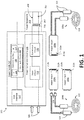
- FIG. 1 shows an example induction heating system 100, according aspects of the present disclosure.
- the induction heating system 100 includes an induction heating power supply 102 and induction heating tools 108 configured to be powered by the power supply 102.
- the induction heating power supply 102 receives input power from a power source 104.
- the power source 104 is indicated in FIG. 1 by arrows 104.
- the power source 104 may be a generator, battery, main electrical power source, welding-type power supply, etc.
- the power source 104 may provide three phase power to the power supply 102.
- the induction heating power supply 102 is configured to generate AC induction-type power (and/or welding-type power) from the power supplied via the power source 104.
- the induction heating power supply 102 includes a user interface 112.
- the user interface 112 may be a remote interface that communicates with the induction heating power supply 102 via a wireless communication channel or a wired cable connection.
- the user interface 112 may include input mechanisms, such as buttons, knobs, dials, touch screens, microphones, mice, keyboards, and so forth to allow an operator to regulate various operating parameters of the induction heating power supply 102.
- the user interface 112 may enable an operator to select a particular operation and/or configuration of the induction heating power supply 102, such as a frequency and/or amplitude of the alternating current produced by the induction heating power supply 102, for example.
- the user interface 112 may enable an operator to select a desired output temperature of an induction heating tool 108 coupled to the induction heating power supply 102.
- the user interface 112 may also include one or more output mechanisms (e.g., display screens and/or audio speakers) configured to provide system feedback to the operator (e.g., temperature and/or travel speed of the induction heating tool 108, etc.).
- the user interface 112 may be configured to provide a warning (and/or alert, alarm, feedback, etc.) via the output mechanisms.
- the warning may be a visual, audio, and/or other type of warning, such as an emphasized visual indication shown on the display screen of the user interface, and/or a klaxon, siren, and/or other sound that may be associated with a warning.
- the induction heating power supply 102 includes control circuitry 106.
- the control circuitry 106 comprises one or more processors 110 and memory circuitry 114.
- the control circuitry 106 further includes instructions and/or circuitry to implement a coupling control process 300, which will be discussed further below.
- the control circuitry 106 is in electrical communication with the user interface 112 and power conversion circuitry 116, further discussed below.
- the control circuitry 106 is further in electrical communication with a power receptacle 202, further discussed below.
- the control circuitry 106 is configured to supply control signals to the power conversion circuitry 116 to control generation of the induction-type power from the input power provided by the power source 104.
- the control circuitry 106 may provide one or more control signals to the power conversion circuitry 116 representative of one or more parameters (e.g., AC frequency and/or amplitude) of the induction-type power generated by the power conversion circuitry 116, and/or a target and/or change in one or more parameters.
- the power conversion circuitry 116 may operate and/or adjust its operation according to the control signal(s).
- control circuitry 106 my use input provided via the user interface 112 and/or feedback from the power conversion circuitry 116 and/or power receptacle 202 when determining the appropriate control signals.
- the user interface 112 may communicate an operator selection to the control circuitry 106, which may process the selection (e.g., via processor 204) and/or retrieve the particular configuration parameters associated with the selection stored in the memory circuitry 114. Thereafter, the control circuitry 106 may send one or more control signals representative of the configuration parameters (and/or configured to produce induction-type power with the configuration parameters) to the power conversion circuitry 116.
- control circuitry 106 is configured to detect characteristics (e.g., voltage, current, resonance, etc.) of the induction-type power provided by the power conversion circuitry 116, such as via one or more feedback signals, for example. In some examples, the control circuitry 106 may determine whether the power receptacle 202 is coupled to a power insert 204 based on the one or more feedback signals. For example, the control circuitry 106 may receive feedback signals indicating a relatively continuous and/or constant (e.g., within a certain threshold range and/or deviation) power and/or resonance in the power conversion circuitry 116.
- characteristics e.g., voltage, current, resonance, etc.
- the control circuitry 106 may determine whether the power receptacle 202 is coupled to a power insert 204 based on the one or more feedback signals. For example, the control circuitry 106 may receive feedback signals indicating a relatively continuous and/or constant (e.g., within a certain threshold range and/or deviation) power and/or resonance in the power conversion
- control circuitry 106 may determine that a relatively continuous and/or constant power and/or resonance indicates that no (and/or negligible) power is being transferred to the power insert 204 and/or induction heating tool(s) 108. Thereby, the control circuitry 106 may determine the power receptacle 202 is not coupled to a power insert 204. As an alternative example, the control circuitry 106 may receive feedback signals indicating a relatively discontinuous and/or changing (e.g., outside of the threshold range and/or deviation) power and/or resonance in the power conversion circuitry 116.
- control circuitry 106 may determine substantial (and/or non-negligible) power is being transferred to the power insert 204 and/or induction heating tool(s) 108, and thus determine the power receptacle 202 is coupled to a power insert 204.
- control circuitry 106 may control the power conversion circuitry 116 based on whether the power receptacle 202 is coupled to a power insert 204. For example, the control circuitry 106 may send one or more control signals to the power conversion circuitry 116 representative of one or more commands to reduce a level, amplitude, and/or amount of induction-type power generated by the power conversion circuitry 116 when the power receptacle 202 is not coupled to a power insert 204. As another example, the control circuitry 106 may send one or more control signals to the power conversion circuitry 116 representative of one or more commands to disable the power conversion circuitry 116 when the power receptacle 202 is not coupled to a power insert 204.
- control circuitry 106 may send one or more control signals to the power conversion circuitry 116 representative of one or more commands to cease generating induction-type power, cease converting power, and/or cease adding electrical power to the electrical bus.
- control circuitry 106 may send one or more control signals to the power conversion circuitry 116 representative of one or more commands to increase and/or decrease an amount (and/or magnitude) of induction-type power generated by the power conversion circuitry 116 (and/or enable the power conversion circuitry 116) when the power receptacle 202 is coupled to a power insert 204.
- the power conversion circuitry 116 includes an input circuit 118, and a conversion circuit 120.
- the input circuit 118 of the power conversion circuitry 116 receives input power from the power source 104.
- the input circuit 118 is configured to perform preliminary (e.g., pre-regulating) operations upon the input power, so as to condition the input power for the conversion circuit 120.
- the input circuit 118 is configured to provide the conversion circuit 120 with pre-regulated power on an electrical bus through which the input circuit 118 and conversion circuit 120 are in electrical communication.
- the input circuit 118 may provide direct current (DC) power on the bus.
- DC direct current
- the input circuit 118 may comprise one or more rectifiers and/or one or more preregulator circuits (e.g., one or more boost converters, stacked boost converters, buck converters, boost-buck converters, and/or other circuits).
- preregulator circuits e.g., one or more boost converters, stacked boost converters, buck converters, boost-buck converters, and/or other circuits.
- operation of the input circuit 118 is regulated and/or controlled by the control circuitry 106 via one or more control signals.
- the input circuit 118 may be configured to adjust a voltage level of the pre-regulated power output by the input circuit 118 by changing characteristics (e.g., activate/deactivate, open/close, turn off/on, etc.) of one or more controllable circuit elements (e.g., transistors, relays, switches, etc.) of the input circuit 118.
- the control circuitry 106 may adjust the characteristics (e.g., frequency, duty cycle, etc.) of the one or more control signals to control and/or regulate the operation of the input circuit 118 via the one or more controllable circuit elements of the input circuit 118.
- the conversion circuit 120 is configured to convert the pre-regulated power provided by the input circuit 118 to the induction-type power used by induction heating tool(s) 108.
- the conversion circuit 120 comprises an inverter circuit configured to generate AC power from DC power provided by the input circuit 118.
- operation of the conversion circuit 120 is regulated and/or controlled by the control circuitry 106 via one or more control signals.
- the control circuitry 106 may regulate and/or control one or more characteristics (e.g., frequency, amplitude.) of the induction-type power provided by the conversion circuit 120, such as in response to input via the user interface 112, for example.
- the control circuitry 106 may adjust the characteristics (e.g., frequency, duty cycle, etc.) of the one or more control signals to control and/or regulate the operation of the conversion circuit 120 via one or more controllable circuit elements of the conversion circuit 120.
- the conversion circuit 120 is in electrical communication with the power receptacle 202.
- the conversion circuit 120 provides the induction-type power to the power receptacle 202 via the electrical communication channel (e.g., via an electrical bus).
- the power receptacle 202 comprises one portion of a modular transformer 200 through which induction-type power is transferred from the induction heating power supply 102 to the induction heating tool(s) 108.
- the power receptacle 202 is part of the induction heating power supply 102.
- the power receptacle 202 may be separable from, and/or separate from, the induction heating power supply 102.
- the power receptacle 202 may be implemented in a junction box (not shown) of the induction heating system 100.
- a power insert 204 may be part of the induction heating power supply 102, rather than a power receptacle 202.
- the power receptacle 202 is in electrical communication with the power conversion circuitry 116, from which the power receptacle receives induction-type power.
- the power receptacle 202 comprises a first portion of a modular transformer 200.
- the power receptacle 202 comprises a primary winding 206 of the modular transformer 200, and a primary core 207 of the transformer core, as discussed further below.
- the primary winding 206 comprises one or more conductors wound around the primary core 207 of the power receptacle 202.
- the primary winding 206 may be hermetically sealed within a housing of the power receptacle 202, such that the conductors of the primary winding 206 are not exposed.
- the primary winding 206 may comprise one or more fluid cooled conductors, such as, for example, a hollow conductor (e.g., copper, aluminum, etc.) cooled by fluid routed through the hollow interior of the conductor, or a conductor within hollow tubing cooled by fluid routed over the conductor within the hollow tubing.
- a cooling system (not shown) may connect to the primary winding 206 to introduce and/or remove cooling fluid. In some examples, such cooling may assist in mitigating heat produced by electrical current flowing through the primary winding 206.
- the power receptacle 202 also includes an opening 208 sized and/or configured to receive a power insert 204 comprising a second portion of the modular transformer 200, as further discussed below.
- a connection detection switch 210 protrudes into the opening.
- the connection detection switch 210 is a movable mechanical switch that is actuated when the power insert 204 is coupled to the power receptacle 202 via insertion into the opening 208.
- the connection detection switch 210 may be an electrical switch, jumper, resistor, circuit, or some other signal generating connection detector.
- actuation of the connection detection switch 210 completes or breaks a connection detection circuit (not shown), or a portion of a connection detection circuit.
- connection detection circuit (or some other circuit) is configured to send a connection signal to the control circuitry 106 representative of the connection status of the power receptacle 202 and/or power insert 204 in view of the connection detection circuit and/or connection detection switch 210. In some examples, actuation of the connection detection switch 210 may otherwise indicate to the control circuitry 106 the connection status of the power receptacle 202 and/or power insert 204.
- both induction heating tools 108 include an induction heating coil 122 configured in a stacked and/or pancake spiral pattern.
- the induction heating coil 122 may be arranged in some other configuration and/or pattern, such as to fit a particular workpiece and/or weld joint configuration, for example.
- the induction heating coil 122 may be implemented using a fixture for repeatable heating of a consistent type of joint.
- the induction coil 110 may comprise a Litz wire (e.g., a jacketed Litz wire).
- the induction coil heating coil 122 may be secured onto and/or into an insulating material (e.g., sewn into an insulating blanket).
- the induction heating tool 108 may be moved by a robotic positioning system in tandem along a welding path together with a conventional welding head, for example a TIG head or any other known type, which "follows" the pre-heating head.
- the induction heating tools 108 and/or induction heating coils 122 are configured to receive induction-type power from the induction heating power supply 102 via a power insert 204.
- the induction heating tools 108 may further be configured to receive coolant from the induction heating power supply 102 and/or some other source.
- the induction heating tools 108 include adapters 124 configured to allow the induction coils 122 to electrically connect to the power inserts 204.
- the adapters 124 connect with conventional plugs of the induction tools 108 on one end, and are configured for electrical connection to the power inserts 204 on the other end.
- the adapters 124 allow for conventional induction heating tools 108 to be used with the power inserts 204.
- the adapters 124 may be omitted, such as for more recent versions of the induction heating tool(s) 108.
- the induction heating coils 122 of the induction heating tool 108a are in electrical communication with power insert 204a, via a fixed connection.
- the induction heating tool 108a is only connectable to the power receptacle 202 via the power insert 204a.
- the induction heating coils 122 of induction heating tool 108b are in electrical communication (e.g., via adapters 124) with plugs 124 that are configured to connect to both/either power insert 204b and/or power insert 204c.
- the plugs 124 may be configured to connect to a wide variety of different power inserts 204.
- the induction heating tool 108b is connectable to the power receptacle 202 via both/either power insert 204b and/or power insert 204c.
- the modular transformer 200 is completed and the induction heating tool 108 may receive induction-type power from the induction heating power supply 102, so that the induction heating tool 108 can perform an induction heating operation.
- the power inserts 204 comprise second portions of the modular transformer 200.
- Each power insert includes a secondary winding 212 and a secondary core 213 of the modular transformer 200.
- the secondary winding 212 comprises one or more conductors twisted in a helix (and/or other pattern) to encircle the secondary core 213 of the power insert 204.
- the secondary winding 212 may be hermetically sealed within a housing of the power insert 204, so there is no exposed wiring.
- the secondary winding 212 may comprise one or more fluid cooled conductors, such as, for example, a hollow conductor (e.g., copper, aluminum, etc.) cooled by fluid routed through the hollow interior of the conductor, or a conductor within hollow tubing cooled by fluid routed over the conductor within the hollow tubing.
- a cooling system (not shown) may connect to the secondary winding 212 (e.g., via the adapters 124) to introduce and/or remove cooling fluid. In some examples, such cooling may assist in mitigating heat produced by electrical current flowing through the secondary winding 212.
- the cooling fluid may also be used to cool the induction heating coil 122.
- Different power inserts 204 may have differently configured secondary windings 212 (e.g., with different numbers of winding turns).
- the secondary winding 212a of the power insert 204a has the most turns of the power inserts 204
- the secondary winding 212b of the power insert 204b has the least turns of the power inserts 204, with the secondary winding 212c of the power insert 204c falling in between.
- the secondary winding 212c of the power insert 204c have the same number of turns as the primary winding 206 of the power receptacle 202.
- FIG. 2a shows an example of the modular transformer 200 that is completed (and/or formed) when the power receptacle 202 is coupled to one of the power inserts 204.
- the connection detection switch 210 is displaced by the coupling, thereby completing the connection detection circuit so as to provide a detectable indication (e.g., a signal or cessation of a signal) to the control circuitry 106 that the modular transformer 200 is completed.
- FIG. 2b is another illustration of the completed modular transformer 200. While the cores 207, 213 and windings 206, 212 are illustrated as being adjacent one another for ease of illustration in FIGS. 1 and 2a , FIG. 2b shows a more practical implementation of the completed modular transformer 200.
- the ferromagnetic core of the modular transformer 200 is divided into two primary cores 207 (e.g., upper core 207a and lower core 207b) of the power receptacle 202 and one secondary core 213 of the power insert 204.
- the primary cores 207 are aligned on opposite sides of the opening 208 of the power receptacle 202.
- Primary windings 206 encircle the primary cores 207.
- the secondary core 213 is retained by the power insert 204, with secondary windings 212 encircling the secondary core 213.
- the power receptacle 202 and power insert 204 are configured such that the secondary core 213 is aligned with the primary cores 207 when the power insert 204 is fully inserted into (and/or coupled to) the power receptacle 202.
- the primary winding 206 and secondary winding 212 may be concentrically aligned (e.g., with the cores 207, 213 at their respective centers) when the power insert 204 is fully inserted into (and/or coupled to) the power receptacle 202.
- FIG. 2c shows an example cross-section of the completed modular transformer 200. While the modular transformer 200 in FIG. 2c shows the primary windings 206 and secondary windings 212 as having the same winding direction, in some examples, the primary windings 206 and secondary windings 212 may have opposite winding directions. As shown, there are approximately twice as many secondary windings 212 as primary windings 206, making the modular transformer 200 a 1:2 step up transformer. In some examples, the modular transformer 200 may be configured differently depending on the primary windings 206 and/or secondary windings 212 of the power receptacle 202 and/or power insert 204 used to complete the modular transformer 200.
- an operator may use different power receptacles 202 and/or power inserts 204 (each having potentially different primary winding 206 and/or secondary winding 212 configurations) with different induction heating power supplies 102 and/or induction heating tools 108 in order to achieve the desired results.
- the operator may manipulate the ratio of primary windings 206 to secondary windings 212 without having to directly access and/or manipulate the exposed wire windings of the transformer.
- the ratio of primary windings 206 to secondary windings 212 is less than ideal for impedance matching and/or the desired step up/down voltage, an operator can use a different power receptacle 202 and/or power insert 204, with a different number (and/or configuration) of primary windings 206 and/or secondary windings 212, without having to directly manipulate any exposed wire windings.
- the modular transformer 200 of FIGS. 2b and 2c is depicted with two separated primary cores 207a, 207b and one secondary core 213a, in some examples, there may be only one primary core 207.
- the primary core 207 may comprise one complete half of the core of the modular transformer 200, while the secondary core 213a may comprise the other half.
- the modular transformer 200 of FIG. 2c is shown with an E-core, in some examples, the modular transformer 200 may instead be configured with one or more other core types, such as a U-core, a P-core, a pot core, a toroid core, etc.
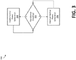
- FIG. 3 shows an example coupling control process 300 of the present disclosure.
- the coupling control process 300 may be implemented via machine readable instructions, such as may be stored in memory circuitry 114 and/or executed by the one or more processors 110.
- the coupling control process 300 may be implemented via discrete and/or analog circuitry of the control circuitry 106.
- the coupling control process 300 is configured to control the power conversion circuitry 116 based on whether the power receptacle 202 is coupled to the power insert 204.
- the coupling control process 300 may be executed by one or more other control process and/or in conjunction with one or more other control processes.
- the coupling control process 300 is implemented as a continuously iterating and/or looping operation in block 302.
- the coupling control process 300 determines whether the power receptacle 202 is coupled to the power insert 204. The coupling control process 300 may make this determination based, at least in part, on feedback received from the power conversion circuitry 116, and/or the connection detection switch 210 (and/or associated connection detection circuit), as discussed above. If the coupling control process 300 determines that the power receptacle 202 is coupled to the power insert 204, the coupling control process 300 proceeds to block 304. If the coupling control process determines that the power receptacle 202 is not coupled to the power insert 204, the coupling control process 300 proceeds to block 306. After blocks 304 and/or 306, the coupling control process returns to block 302.
- the coupling control process 300 determines that the power receptacle 202 is coupled to the power insert 204, block 304 of the coupling control process 300 executes. At block 304, the coupling control process 300 enables normal power generation of the power conversion circuitry 116 to proceed. If normal power generation had previously been interrupted (e.g., by block 306), the coupling control process 300 resumes normal power generation.
- the coupling control process 300 interrupts normal power generation of the power conversion circuitry 116, so that induction-type power is not continually added to the system bus with nowhere to go.
- the interruption of normal power generation may comprise disabling of the power conversion circuitry 116 (e.g., via a cessation of control signals or use of control signals configured to disable), reducing the amount of induction-type power produced by the power conversion circuitry 116 (e.g., via representative control signals), and/or other appropriate action.
- the interruption of normal power generation may further comprise generating a warning (and/or alert/alarm), such as via the user interface 112 and/or some other interface (e.g., the interface of a remote device, mobile device, etc.).
- a warning and/or alert/alarm
- the coupling control process 300 returns to block 302.
- the present methods and systems may be realized in hardware, software, and/or a combination of hardware and software.
- Example implementations include an application specific integrated circuit and/or a programmable control circuit.
Landscapes
- Physics & Mathematics (AREA)
- Electromagnetism (AREA)
- Engineering & Computer Science (AREA)
- Power Engineering (AREA)
- Computer Networks & Wireless Communication (AREA)
- General Induction Heating (AREA)
Abstract
Description
- The present disclosure generally relates to induction heating systems and, more particularly, to modular transformers and induction heating systems having modular transformers.
- Induction heating refers to a method for producing heat in a localized area on a susceptible (typically metal) object. Induction heating involves applying an alternating current (AC) electric signal to a heating loop placed near a specific location on and/or near a piece of metal to be heated. The varying current in the loop creates a varying magnetic flux within the metal to be heated. Current is induced in the metal by the magnetic flux and the internal resistance of the metal causes it to heat up in a relatively short period of time.
- Induction heating may be used for many different purposes including curing adhesives, hardening of metals, brazing, soldering, and other fabrication processes in which heat is a necessary or desirable agent. Induction heating may also be used in conjunction with welding systems, such as, for example, for heating materials before, during, and/or after welding.
- Limitations and disadvantages of conventional and traditional approaches will become apparent to one of skill in the art, through comparison of such systems with the present disclosure as set forth in the remainder of the present application with reference to the drawings.
- The present disclosure is directed to apparatus, systems, and methods for induction heating, for example, substantially as illustrated by and/or described in connection with at least one of the figures, and as set forth more completely in the claims.
- These and other advantages, aspects and novel features of the present disclosure, as well as details of an illustrated example thereof, will be more fully understood from the following description and drawings.
-
-
FIG. 1 is a block diagram of an example induction heating system, in accordance with aspects of this disclosure. -
FIG. 2a is a block diagram illustrating coupling of a power receptacle and power insert of a modular transformer of the induction heating system ofFIG. 1 , in accordance with aspects of this disclosure. -
FIG. 2b is a block diagram illustrating alignment of the transformer cores and windings of the coupled power receptacle and power insert ofFIG. 2a , in accordance with aspects of this disclosure. -
FIG. 2c is a cross-section of the connected power receptacle and power insert ofFIG. 2b along theline 2c-2c inFIG. 2b , in accordance with aspects of this disclosure. -
FIG. 3 is a block diagram illustrating an example coupling control process, in accordance with aspects of this disclosure. - The figures are not necessarily to scale. Where appropriate, the same or similar reference numerals are used in the figures to refer to similar or identical elements. For example, reference numerals utilizing lettering (e.g.,
induction heating tool 108a,induction heating tool 108b) refer to instances of the same reference numeral that does not have the lettering (e.g., induction heating tool(s) 108). - Preferred examples of the present disclosure may be described hereinbelow with reference to the accompanying drawings. In the following description, well-known functions or constructions are not described in detail because they may obscure the disclosure in unnecessary detail. For this disclosure, the following terms and definitions shall apply.
- As used herein, "and/or" means any one or more of the items in the list joined by "and/or". As an example, "x and/or y" means any element of the three-element set {(x), (y), (x, y)}. In other words, "x and/or y" means "one or both of x and y". As another example, "x, y, and/or z" means any element of the seven-element set {(x), (y), (z), (x, y), (x, z), (y, z), (x, y, z)}. In other words, "x, y and/or z" means "one or more of x, y and z".
- As used herein the terms "circuits" and "circuitry" refer to physical electronic or electrical components (i.e., hardware) and any software and/or firmware ("code") which may configure the hardware, be executed by the hardware, and or otherwise be associated with the hardware. As used herein, for example, a particular processor and memory may comprise a first "circuit" when executing a first one or more lines of code and may comprise a second "circuit" when executing a second one or more lines of code. As utilized herein, circuitry is "operable" and/or "configured" to perform a function whenever the circuitry comprises the necessary hardware and/or code (if any is necessary) to perform the function, regardless of whether performance of the function is disabled or enabled (e.g., by a user-configurable setting, factory trim, etc.).
- As used herein, a control circuit may include digital and/or analog circuitry, discrete and/or integrated circuitry, microprocessors, DSPs, etc., software, hardware and/or firmware, located on one or more boards, that form part or all of a controller, and/or are used to control a welding process, and/or a device such as a power source or wire feeder.
- As used herein, the term "processor" means processing devices, apparatus, programs, circuits, components, systems, and subsystems, whether implemented in hardware, tangibly embodied software, or both, and whether or not it is programmable. The term "processor" as used herein includes, but is not limited to, one or more computing devices, hardwired circuits, signal-modifying devices and systems, devices and machines for controlling systems, central processing units, programmable devices and systems, field-programmable gate arrays, application-specific integrated circuits, systems on a chip, systems comprising discrete elements and/or circuits, state machines, virtual machines, data processors, processing facilities, and combinations of any of the foregoing. The processor may be, for example, any type of general purpose microprocessor or microcontroller, a digital signal processing (DSP) processor, an application-specific integrated circuit (ASIC). The processor may be coupled to, and/or integrated with a memory device.
- As used, herein, the term "memory" and/or "memory device" means computer hardware or circuitry to store information for use by a processor and/or other digital device. The memory and/or memory device can be any suitable type of computer memory or any other type of electronic storage medium, such as, for example, read-only memory (ROM), random access memory (RAM), cache memory, compact disc read-only memory (CDROM), electro-optical memory, magneto-optical memory, programmable read-only memory (PROM), erasable programmable read-only memory (EPROM), electrically-erasable programmable read-only memory (EEPROM), a computer-readable medium, or the like.
- As utilized herein, the terms "e.g.," and "for example" set off lists of one or more non-limiting examples, instances, or illustrations.
- The term "power" is used throughout this specification for convenience, but also includes related measures such as energy, current, voltage, and enthalpy. For example, controlling "power" may involve controlling voltage, current, energy, and/or enthalpy, and/or controlling based on "power" may involve controlling based on voltage, current, energy, and/or enthalpy.
- As used herein, a welding-type power supply and/or power source refers to any device capable of, when power is applied thereto, supplying welding, cladding, plasma cutting, induction heating, laser (including laser welding, laser hybrid, and laser cladding), carbon arc cutting or gouging and/or resistive preheating, including but not limited to transformer-rectifiers, inverters, converters, resonant power supplies, quasi-resonant power supplies, switch-mode power supplies, etc., as well as control circuitry and other ancillary circuitry associated therewith.
- As used herein, welding-type power refers to power suitable for welding, cladding, plasma cutting, induction heating, CAC-A and/or hot wire welding/preheating (including laser welding and laser cladding), carbon arc cutting or gouging, and/or resistive preheating.
- As used herein, an induction heating system includes a power source that can provide power for induction heating, such as, for example, via an induction heating tool that can induce heat in a workpiece.
- As used herein, an induction heating power supply refers to a power supply that is capable of providing induction-type power to an induction heating tool, induction heating element, induction heating coil, and/or induction heating head, to induce current flow and/or heat in a (typically metallic) workpiece.
- As used herein, induction-type power refers to power suitable for an induction heating tool, induction heating element, induction heating coil, and/or induction heating head, to induce current flow and/or heat in a (typically metallic) workpiece.
- As used herein, an induction heating tool refers to an inductive load such as an induction heating coil, an induction heating winding, and/or an induction heating coil, which heats a workpiece by induction.
- As used herein, a winding refers to conductor that induces a magnetic field when current flows therein.
- As used herein, the terms "coupled," "coupled to," and "coupled with," each mean a structural and/or electrical connection, whether attached, affixed, connected, joined, fastened, linked, and/or otherwise secured. As used herein, the term "attach" means to affix, couple, connect, join, fasten, link, and/or otherwise secure. As used herein, the term "connect" means to attach, affix, couple, join, fasten, link, and/or otherwise secure.
- As used herein, the terms "about" and/or "approximately," when used to modify or describe a value (or range of values), position, orientation, and/or action, mean reasonably close to that value, range of values, position, orientation, and/or action. Thus, the examples described herein are not limited to only the recited values, ranges of values, positions, orientations, and/or actions but rather should include reasonably workable deviations.
- Some examples of the present disclosure relate to an induction heating system, comprising a first power coupler comprising a first magnetic core, the first power coupler configured for electrical communication with an induction heating power supply, and a second power coupler comprising a second magnetic core, the second power coupler configured for electrical communication with an induction heating tool, where the first power coupler and second power coupler are configured to magnetically couple the first magnetic core and the second magnetic core to form a transformer through which the induction heating power is transferred to the induction heating tool.
- In some examples, the first power coupler is configured for releasable attachment to the induction heating power supply. In some examples, the second power coupler is configured for releasable attachment to the induction heating tool. In some examples, the first power coupler further comprises a first winding wound around the first magnetic core and the second power coupler further comprises a second winding wound around the second magnetic core. In some examples, the first winding is hermetically sealed within a first housing that retains the first magnetic core, the second winding is hermetically sealed within a second housing that retains the second magnetic core, and the first and second housings are configured to align the first core with the second core when the first and second power couplers are connected together. In some examples, the first power coupler and the second power coupler are further configured to disconnect to decouple the magnetic coupling between the first magnetic core and the second magnetic core. In some examples, the induction heating power supply is configured to disable when the first power coupler and second power coupler are decoupled. In some examples, the system further comprises control circuitry configured to detect when the first power coupler and second power coupler are decoupled, and the control circuitry is configured to disable the induction heating power supply in response to the detection.
- Some examples of the present disclosure relate to a method of impedance matching an induction heating power supply, comprising decoupling a first power coupler in electrical communication with an induction heating power supply from a second power coupler in electrical communication with an induction heating tool, the first power coupler comprising a first magnetic core and the second power coupler comprising a second magnetic core, where the first power coupler and second power coupler are configured to magnetically couple the first magnetic core and the second magnetic core to form a transformer through which induction heating power is transferred from the induction power supply to the induction heating tool. The method further comprises coupling the first power coupler to a third power coupler in electrical communication with the induction heating tool or an alternate induction heating tool, the third power coupler comprising a third magnetic core, where the first power coupler and third power coupler are configured to magnetically couple the first magnetic core and the third magnetic core to form a transformer through which the induction heating power is transferred to the induction heating tool or the alternate induction heating tool.
- In some examples, the first power coupler further comprises a first winding wound around the first magnetic core, the second power coupler further comprises a second winding wound around the second magnetic core, and the third power coupler further comprises a third winding wound around the third magnetic core. In some examples, the second winding is different than the third winding. In some examples, the second winding comprises a second conductor having a second number of turns and the third winding comprises a third conductor having a third number of turns, where the second number of turns is different than the third number of turns. In some examples, the first winding is hermetically sealed within a first housing that retains the first magnetic core, the second winding is hermetically sealed within a second housing that retains the second magnetic core, the third winding is hermetically sealed within a third housing that retains the third magnetic core, the first and second housings are configured to align the first core with the second core when the first and second power couplers are connected together, and the first and third housings are configured to align the first core with the third core when the first and third power couplers are connected together. In some examples, the method further comprises disabling the induction heating power supply in response to detecting the decoupling of the first power coupler from the second power coupler, and enabling the induction heating power supply in response to detecting the coupling of the first power coupler to the third power.
- Some examples of the present disclosure relate to an induction heating power supply, comprising power conversion circuitry configured to receive input power from a power source and convert the input power to induction heating power, and a first power coupler in electrical communication with the power conversion circuitry, the first power coupler comprising a first magnetic core and configured to couple to a second power coupler comprising a second magnetic core, the second power coupler being in electrical communication with an induction heating tool, where the first power coupler and second power coupler are configured to magnetically couple the first magnetic core and the second magnetic core to form a transformer through which the induction heating power is transferred to the induction heating tool.
- In some examples, the first power coupler is releasably attached to the induction heating power supply. In some examples, the first power coupler further comprises a first winding wound around the first magnetic core, wherein the first winding is hermetically sealed within a first housing that retains the first magnetic core. In some examples, the first power coupler comprises a power receptacle having an opening configured to receive the second power coupler. In some examples, the first power coupler comprises an insert configured to fit within a receptacle opening of the second power coupler. In some examples, the system further comprises control circuitry configured to disable the power conversion circuitry in response to a signal representative of decoupled first and second power couplers.
- Some examples of the present disclosure relate to induction heating systems. In some examples, an induction heating system includes an induction heating power supply and an induction heating tool coupled together through a modular transformer. In some examples, the modular transformer comprises a first coupler (e.g., a power receptacle) and a second coupler (e.g., a power insert) configured to couple together to complete the modular transformer, and/or decouple to separate the modular transformer. In some examples, the first coupler is in electrical communication with the induction heating power supply, and the second coupler is in electrical communication with the induction heating tool. When the first and second couplers are coupled together to complete the modular transformer, induction-type power flows through the modular transformer from the induction heating power supply to the induction heating tool.
- Induction heating systems use impedance matching to match the impedance of an induction heating power supply to the impedance of an induction heating tool. Impedance matching increases the efficiency of power transfer from the induction heating power supply to the induction heating tool. One particular strategy for impedance matching is through step up and/or step down transformers.
- Conventionally, induction heating systems used one or more hardwired transformers to step up or step down an output voltage, depending on the configuration, needs, and/or impedance of the induction heating tool and/or system. The ratio of the number of primary windings compared to (and/or in proportion to) the number of secondary windings determines the extent to which voltage is stepped up or stepped down. Since conventional induction heating systems use hardwired transformers, an operator must directly access and manipulate exposed conductor wire windings of the transformer in order to manipulate the ratio of primary windings to secondary windings.
- Advantageously, the modular transformer contemplated by the present disclosure allows an operator to manipulate the ratio of primary windings to secondary windings without having to directly access and/or manipulate the exposed wire windings of the transformer. In particular, the first coupler comprises a primary set of windings of the modular transformer hermetically sealed within a first housing. The second coupler comprises a secondary set of windings of the modular transformer hermetically sealed within a second housing. If the ratio of primary windings to secondary windings is less than ideal for impedance matching and/or the desired step up/down voltage, an operator can use a different (e.g., third) coupler, with a different number (and/or configuration) of primary/secondary windings, and use that coupler as the first or second coupler of the modular transformer, all without having to directly manipulate any exposed wire windings. In some examples, the induction heating system of the present disclosure may be provided with a plurality of first and/or second couplers, with different windings and/or configurations, that may be swapped in and/or out of the system to allow an operator to manipulate the primary to secondary windings ratio without having to directly access the exposed electrical wires of the transformer.
-
FIG. 1 shows an exampleinduction heating system 100, according aspects of the present disclosure. In the example ofFIG. 1 , theinduction heating system 100 includes an inductionheating power supply 102 andinduction heating tools 108 configured to be powered by thepower supply 102. As shown, the inductionheating power supply 102 receives input power from apower source 104. Thepower source 104 is indicated inFIG. 1 byarrows 104. In some examples, thepower source 104 may be a generator, battery, main electrical power source, welding-type power supply, etc. In some examples, thepower source 104 may provide three phase power to thepower supply 102. In the example ofFIG. 1 , the inductionheating power supply 102 is configured to generate AC induction-type power (and/or welding-type power) from the power supplied via thepower source 104. - As illustrated in the example of
FIG. 1 , the inductionheating power supply 102 includes auser interface 112. In some examples, theuser interface 112 may be a remote interface that communicates with the inductionheating power supply 102 via a wireless communication channel or a wired cable connection. In some examples, theuser interface 112 may include input mechanisms, such as buttons, knobs, dials, touch screens, microphones, mice, keyboards, and so forth to allow an operator to regulate various operating parameters of the inductionheating power supply 102. For example, theuser interface 112 may enable an operator to select a particular operation and/or configuration of the inductionheating power supply 102, such as a frequency and/or amplitude of the alternating current produced by the inductionheating power supply 102, for example. Similarly, theuser interface 112 may enable an operator to select a desired output temperature of aninduction heating tool 108 coupled to the inductionheating power supply 102. Theuser interface 112 may also include one or more output mechanisms (e.g., display screens and/or audio speakers) configured to provide system feedback to the operator (e.g., temperature and/or travel speed of theinduction heating tool 108, etc.). In some examples, theuser interface 112 may be configured to provide a warning (and/or alert, alarm, feedback, etc.) via the output mechanisms. The warning may be a visual, audio, and/or other type of warning, such as an emphasized visual indication shown on the display screen of the user interface, and/or a klaxon, siren, and/or other sound that may be associated with a warning. - In the example of
FIG. 1 , the inductionheating power supply 102 includescontrol circuitry 106. As shown, thecontrol circuitry 106 comprises one ormore processors 110 andmemory circuitry 114. In the example ofFIG. 1 , thecontrol circuitry 106 further includes instructions and/or circuitry to implement acoupling control process 300, which will be discussed further below. As shown, thecontrol circuitry 106 is in electrical communication with theuser interface 112 andpower conversion circuitry 116, further discussed below. Thecontrol circuitry 106 is further in electrical communication with apower receptacle 202, further discussed below. - In the example of
FIG. 1 , thecontrol circuitry 106 is configured to supply control signals to thepower conversion circuitry 116 to control generation of the induction-type power from the input power provided by thepower source 104. For example, thecontrol circuitry 106 may provide one or more control signals to thepower conversion circuitry 116 representative of one or more parameters (e.g., AC frequency and/or amplitude) of the induction-type power generated by thepower conversion circuitry 116, and/or a target and/or change in one or more parameters. In such an example, thepower conversion circuitry 116 may operate and/or adjust its operation according to the control signal(s). - In some examples, the
control circuitry 106 my use input provided via theuser interface 112 and/or feedback from thepower conversion circuitry 116 and/orpower receptacle 202 when determining the appropriate control signals. For example, theuser interface 112 may communicate an operator selection to thecontrol circuitry 106, which may process the selection (e.g., via processor 204) and/or retrieve the particular configuration parameters associated with the selection stored in thememory circuitry 114. Thereafter, thecontrol circuitry 106 may send one or more control signals representative of the configuration parameters (and/or configured to produce induction-type power with the configuration parameters) to thepower conversion circuitry 116. - In some examples, the
control circuitry 106 is configured to detect characteristics (e.g., voltage, current, resonance, etc.) of the induction-type power provided by thepower conversion circuitry 116, such as via one or more feedback signals, for example. In some examples, thecontrol circuitry 106 may determine whether thepower receptacle 202 is coupled to a power insert 204 based on the one or more feedback signals. For example, thecontrol circuitry 106 may receive feedback signals indicating a relatively continuous and/or constant (e.g., within a certain threshold range and/or deviation) power and/or resonance in thepower conversion circuitry 116. In some examples, thecontrol circuitry 106 may determine that a relatively continuous and/or constant power and/or resonance indicates that no (and/or negligible) power is being transferred to the power insert 204 and/or induction heating tool(s) 108. Thereby, thecontrol circuitry 106 may determine thepower receptacle 202 is not coupled to a power insert 204. As an alternative example, thecontrol circuitry 106 may receive feedback signals indicating a relatively discontinuous and/or changing (e.g., outside of the threshold range and/or deviation) power and/or resonance in thepower conversion circuitry 116. From this, thecontrol circuitry 106 may determine substantial (and/or non-negligible) power is being transferred to the power insert 204 and/or induction heating tool(s) 108, and thus determine thepower receptacle 202 is coupled to a power insert 204. - In some examples, the
control circuitry 106 may control thepower conversion circuitry 116 based on whether thepower receptacle 202 is coupled to a power insert 204. For example, thecontrol circuitry 106 may send one or more control signals to thepower conversion circuitry 116 representative of one or more commands to reduce a level, amplitude, and/or amount of induction-type power generated by thepower conversion circuitry 116 when thepower receptacle 202 is not coupled to a power insert 204. As another example, thecontrol circuitry 106 may send one or more control signals to thepower conversion circuitry 116 representative of one or more commands to disable thepower conversion circuitry 116 when thepower receptacle 202 is not coupled to a power insert 204. For example, thecontrol circuitry 106 may send one or more control signals to thepower conversion circuitry 116 representative of one or more commands to cease generating induction-type power, cease converting power, and/or cease adding electrical power to the electrical bus. Alternatively, or additionally, thecontrol circuitry 106 may send one or more control signals to thepower conversion circuitry 116 representative of one or more commands to increase and/or decrease an amount (and/or magnitude) of induction-type power generated by the power conversion circuitry 116 (and/or enable the power conversion circuitry 116) when thepower receptacle 202 is coupled to a power insert 204. - In the example of
FIG. 1 , thepower conversion circuitry 116 includes aninput circuit 118, and aconversion circuit 120. As shown, theinput circuit 118 of thepower conversion circuitry 116 receives input power from thepower source 104. Theinput circuit 118 is configured to perform preliminary (e.g., pre-regulating) operations upon the input power, so as to condition the input power for theconversion circuit 120. In some examples, theinput circuit 118 is configured to provide theconversion circuit 120 with pre-regulated power on an electrical bus through which theinput circuit 118 andconversion circuit 120 are in electrical communication. For example, theinput circuit 118 may provide direct current (DC) power on the bus. In some examples, theinput circuit 118 may comprise one or more rectifiers and/or one or more preregulator circuits (e.g., one or more boost converters, stacked boost converters, buck converters, boost-buck converters, and/or other circuits). - In some examples, operation of the
input circuit 118 is regulated and/or controlled by thecontrol circuitry 106 via one or more control signals. For example, theinput circuit 118 may be configured to adjust a voltage level of the pre-regulated power output by theinput circuit 118 by changing characteristics (e.g., activate/deactivate, open/close, turn off/on, etc.) of one or more controllable circuit elements (e.g., transistors, relays, switches, etc.) of theinput circuit 118. In such an example, thecontrol circuitry 106 may adjust the characteristics (e.g., frequency, duty cycle, etc.) of the one or more control signals to control and/or regulate the operation of theinput circuit 118 via the one or more controllable circuit elements of theinput circuit 118. - In the example of
FIG. 1 , theconversion circuit 120 is configured to convert the pre-regulated power provided by theinput circuit 118 to the induction-type power used by induction heating tool(s) 108. In some examples, theconversion circuit 120 comprises an inverter circuit configured to generate AC power from DC power provided by theinput circuit 118. In some examples, operation of theconversion circuit 120 is regulated and/or controlled by thecontrol circuitry 106 via one or more control signals. For example, thecontrol circuitry 106 may regulate and/or control one or more characteristics (e.g., frequency, amplitude.) of the induction-type power provided by theconversion circuit 120, such as in response to input via theuser interface 112, for example. In some examples, thecontrol circuitry 106 may adjust the characteristics (e.g., frequency, duty cycle, etc.) of the one or more control signals to control and/or regulate the operation of theconversion circuit 120 via one or more controllable circuit elements of theconversion circuit 120. - In the example of
FIG. 1 , theconversion circuit 120 is in electrical communication with thepower receptacle 202. Theconversion circuit 120 provides the induction-type power to thepower receptacle 202 via the electrical communication channel (e.g., via an electrical bus). In some examples, thepower receptacle 202 comprises one portion of amodular transformer 200 through which induction-type power is transferred from the inductionheating power supply 102 to the induction heating tool(s) 108. - In the example of
FIG. 1 , thepower receptacle 202 is part of the inductionheating power supply 102. In some examples, thepower receptacle 202 may be separable from, and/or separate from, the inductionheating power supply 102. In some examples, thepower receptacle 202 may be implemented in a junction box (not shown) of theinduction heating system 100. In some examples, a power insert 204 may be part of the inductionheating power supply 102, rather than apower receptacle 202. - As shown, the
power receptacle 202 is in electrical communication with thepower conversion circuitry 116, from which the power receptacle receives induction-type power. In the example ofFIG. 1 , thepower receptacle 202 comprises a first portion of amodular transformer 200. In particular, thepower receptacle 202 comprises a primary winding 206 of themodular transformer 200, and aprimary core 207 of the transformer core, as discussed further below. The primary winding 206 comprises one or more conductors wound around theprimary core 207 of thepower receptacle 202. The primary winding 206 may be hermetically sealed within a housing of thepower receptacle 202, such that the conductors of the primary winding 206 are not exposed. - In some examples, the primary winding 206 may comprise one or more fluid cooled conductors, such as, for example, a hollow conductor (e.g., copper, aluminum, etc.) cooled by fluid routed through the hollow interior of the conductor, or a conductor within hollow tubing cooled by fluid routed over the conductor within the hollow tubing. In some examples, a cooling system (not shown) may connect to the primary winding 206 to introduce and/or remove cooling fluid. In some examples, such cooling may assist in mitigating heat produced by electrical current flowing through the primary winding 206.
- As shown, the
power receptacle 202 also includes anopening 208 sized and/or configured to receive a power insert 204 comprising a second portion of themodular transformer 200, as further discussed below. In the example ofFIG. 1 , aconnection detection switch 210 protrudes into the opening. As shown, theconnection detection switch 210 is a movable mechanical switch that is actuated when the power insert 204 is coupled to thepower receptacle 202 via insertion into theopening 208. In some examples, theconnection detection switch 210 may be an electrical switch, jumper, resistor, circuit, or some other signal generating connection detector. In some examples, actuation of theconnection detection switch 210 completes or breaks a connection detection circuit (not shown), or a portion of a connection detection circuit. In some examples, the connection detection circuit (or some other circuit) is configured to send a connection signal to thecontrol circuitry 106 representative of the connection status of thepower receptacle 202 and/or power insert 204 in view of the connection detection circuit and/orconnection detection switch 210. In some examples, actuation of theconnection detection switch 210 may otherwise indicate to thecontrol circuitry 106 the connection status of thepower receptacle 202 and/or power insert 204. - In the example of
FIG. 1 , there are shown threepower inserts induction heating tools FIG. 1 , in some examples, theinduction heating tools 108 may be entirely different. As shown, bothinduction heating tools 108 include aninduction heating coil 122 configured in a stacked and/or pancake spiral pattern. In some examples, theinduction heating coil 122 may be arranged in some other configuration and/or pattern, such as to fit a particular workpiece and/or weld joint configuration, for example. In some examples, theinduction heating coil 122 may be implemented using a fixture for repeatable heating of a consistent type of joint. In some examples, theinduction coil 110 may comprise a Litz wire (e.g., a jacketed Litz wire). In some examples, the inductioncoil heating coil 122 may be secured onto and/or into an insulating material (e.g., sewn into an insulating blanket). In some examples, theinduction heating tool 108 may be moved by a robotic positioning system in tandem along a welding path together with a conventional welding head, for example a TIG head or any other known type, which "follows" the pre-heating head. - In the example of
FIG. 1 , theinduction heating tools 108 and/or induction heating coils 122 are configured to receive induction-type power from the inductionheating power supply 102 via a power insert 204. In some examples, theinduction heating tools 108 may further be configured to receive coolant from the inductionheating power supply 102 and/or some other source. As shown, theinduction heating tools 108 includeadapters 124 configured to allow the induction coils 122 to electrically connect to the power inserts 204. Theadapters 124 connect with conventional plugs of theinduction tools 108 on one end, and are configured for electrical connection to the power inserts 204 on the other end. Theadapters 124 allow for conventionalinduction heating tools 108 to be used with the power inserts 204. In some examples, theadapters 124 may be omitted, such as for more recent versions of the induction heating tool(s) 108. - In the example of
FIG. 1 , the induction heating coils 122 of theinduction heating tool 108a are in electrical communication withpower insert 204a, via a fixed connection. Thus, theinduction heating tool 108a is only connectable to thepower receptacle 202 via thepower insert 204a. As shown, the induction heating coils 122 ofinduction heating tool 108b are in electrical communication (e.g., via adapters 124) withplugs 124 that are configured to connect to both/eitherpower insert 204b and/orpower insert 204c. In some examples, theplugs 124 may be configured to connect to a wide variety of different power inserts 204. Thus, theinduction heating tool 108b is connectable to thepower receptacle 202 via both/eitherpower insert 204b and/orpower insert 204c. When thepower receptacle 202 is coupled to the power insert 204 of aninduction heating tool 108, themodular transformer 200 is completed and theinduction heating tool 108 may receive induction-type power from the inductionheating power supply 102, so that theinduction heating tool 108 can perform an induction heating operation. - In the example of
FIG. 1 , the power inserts 204 comprise second portions of themodular transformer 200. Each power insert includes a secondary winding 212 and asecondary core 213 of themodular transformer 200. The secondary winding 212 comprises one or more conductors twisted in a helix (and/or other pattern) to encircle thesecondary core 213 of the power insert 204. The secondary winding 212 may be hermetically sealed within a housing of the power insert 204, so there is no exposed wiring. - In some examples, the secondary winding 212 may comprise one or more fluid cooled conductors, such as, for example, a hollow conductor (e.g., copper, aluminum, etc.) cooled by fluid routed through the hollow interior of the conductor, or a conductor within hollow tubing cooled by fluid routed over the conductor within the hollow tubing. In some examples, a cooling system (not shown) may connect to the secondary winding 212 (e.g., via the adapters 124) to introduce and/or remove cooling fluid. In some examples, such cooling may assist in mitigating heat produced by electrical current flowing through the secondary winding 212. In some examples, the cooling fluid may also be used to cool the
induction heating coil 122. - Different power inserts 204 may have differently configured secondary windings 212 (e.g., with different numbers of winding turns). In the example of
FIG. 1 , the secondary winding 212a of thepower insert 204a has the most turns of the power inserts 204, and the secondary winding 212b of thepower insert 204b has the least turns of the power inserts 204, with the secondary winding 212c of thepower insert 204c falling in between. As shown, the secondary winding 212c of thepower insert 204c have the same number of turns as the primary winding 206 of thepower receptacle 202. -
FIG. 2a shows an example of themodular transformer 200 that is completed (and/or formed) when thepower receptacle 202 is coupled to one of the power inserts 204. When the power insert 204 is securely inserted into (and/or coupled to) thepower receptacle 202, theprimary core 207 of thepower receptacle 202 andsecondary core 213 of the power insert 204 align to complete themodular transformer 200. As shown, theconnection detection switch 210 is displaced by the coupling, thereby completing the connection detection circuit so as to provide a detectable indication (e.g., a signal or cessation of a signal) to thecontrol circuitry 106 that themodular transformer 200 is completed. -
FIG. 2b is another illustration of the completedmodular transformer 200. While thecores windings FIGS. 1 and2a ,FIG. 2b shows a more practical implementation of the completedmodular transformer 200. As shown, the ferromagnetic core of themodular transformer 200 is divided into two primary cores 207 (e.g., upper core 207a andlower core 207b) of thepower receptacle 202 and onesecondary core 213 of the power insert 204. Theprimary cores 207 are aligned on opposite sides of theopening 208 of thepower receptacle 202.Primary windings 206 encircle theprimary cores 207. Thesecondary core 213 is retained by the power insert 204, withsecondary windings 212 encircling thesecondary core 213. Thepower receptacle 202 and power insert 204 are configured such that thesecondary core 213 is aligned with theprimary cores 207 when the power insert 204 is fully inserted into (and/or coupled to) thepower receptacle 202. In some examples, the primary winding 206 and secondary winding 212 may be concentrically aligned (e.g., with thecores power receptacle 202. -
FIG. 2c shows an example cross-section of the completedmodular transformer 200. While themodular transformer 200 inFIG. 2c shows theprimary windings 206 andsecondary windings 212 as having the same winding direction, in some examples, theprimary windings 206 andsecondary windings 212 may have opposite winding directions. As shown, there are approximately twice as manysecondary windings 212 asprimary windings 206, making the modular transformer 200 a 1:2 step up transformer. In some examples, themodular transformer 200 may be configured differently depending on theprimary windings 206 and/orsecondary windings 212 of thepower receptacle 202 and/or power insert 204 used to complete themodular transformer 200. - In operation, an operator may use
different power receptacles 202 and/or power inserts 204 (each having potentially different primary winding 206 and/or secondary winding 212 configurations) with different inductionheating power supplies 102 and/orinduction heating tools 108 in order to achieve the desired results. By usingdifferent power receptacles 202 and/or power inserts 204, the operator may manipulate the ratio ofprimary windings 206 tosecondary windings 212 without having to directly access and/or manipulate the exposed wire windings of the transformer. If the ratio ofprimary windings 206 tosecondary windings 212 is less than ideal for impedance matching and/or the desired step up/down voltage, an operator can use adifferent power receptacle 202 and/or power insert 204, with a different number (and/or configuration) ofprimary windings 206 and/orsecondary windings 212, without having to directly manipulate any exposed wire windings. - While the
modular transformer 200 ofFIGS. 2b and2c is depicted with two separatedprimary cores 207a, 207b and onesecondary core 213a, in some examples, there may be only oneprimary core 207. For example, there may be only an upper primary core 207a or only a lowerprimary core 207b, with correspondingwindings 206. In such an example, theprimary core 207 may comprise one complete half of the core of themodular transformer 200, while thesecondary core 213a may comprise the other half. Additionally, though themodular transformer 200 ofFIG. 2c is shown with an E-core, in some examples, themodular transformer 200 may instead be configured with one or more other core types, such as a U-core, a P-core, a pot core, a toroid core, etc. -
FIG. 3 shows an examplecoupling control process 300 of the present disclosure. In some examples, thecoupling control process 300 may be implemented via machine readable instructions, such as may be stored inmemory circuitry 114 and/or executed by the one ormore processors 110. In some examples, thecoupling control process 300 may be implemented via discrete and/or analog circuitry of thecontrol circuitry 106. Thecoupling control process 300 is configured to control thepower conversion circuitry 116 based on whether thepower receptacle 202 is coupled to the power insert 204. In some examples, thecoupling control process 300 may be executed by one or more other control process and/or in conjunction with one or more other control processes. - In the example of
FIG. 3 , thecoupling control process 300 is implemented as a continuously iterating and/or looping operation inblock 302. Atblock 302, thecoupling control process 300 determines whether thepower receptacle 202 is coupled to the power insert 204. Thecoupling control process 300 may make this determination based, at least in part, on feedback received from thepower conversion circuitry 116, and/or the connection detection switch 210 (and/or associated connection detection circuit), as discussed above. If thecoupling control process 300 determines that thepower receptacle 202 is coupled to the power insert 204, thecoupling control process 300 proceeds to block 304. If the coupling control process determines that thepower receptacle 202 is not coupled to the power insert 204, thecoupling control process 300 proceeds to block 306. Afterblocks 304 and/or 306, the coupling control process returns to block 302. - If the
coupling control process 300 determines that thepower receptacle 202 is coupled to the power insert 204, block 304 of thecoupling control process 300 executes. Atblock 304, thecoupling control process 300 enables normal power generation of thepower conversion circuitry 116 to proceed. If normal power generation had previously been interrupted (e.g., by block 306), thecoupling control process 300 resumes normal power generation. - If the coupling control process determines that the
power receptacle 202 is not coupled to the power insert 204, block 306 executes. Atblock 306, thecoupling control process 300 interrupts normal power generation of thepower conversion circuitry 116, so that induction-type power is not continually added to the system bus with nowhere to go. In some examples, the interruption of normal power generation may comprise disabling of the power conversion circuitry 116 (e.g., via a cessation of control signals or use of control signals configured to disable), reducing the amount of induction-type power produced by the power conversion circuitry 116 (e.g., via representative control signals), and/or other appropriate action. In some examples, the interruption of normal power generation may further comprise generating a warning (and/or alert/alarm), such as via theuser interface 112 and/or some other interface (e.g., the interface of a remote device, mobile device, etc.). Afterwards, thecoupling control process 300 returns to block 302. - The present methods and systems may be realized in hardware, software, and/or a combination of hardware and software. Example implementations include an application specific integrated circuit and/or a programmable control circuit.
- While the present apparatuses, systems, and/or methods have been described with reference to certain implementations, it will be understood by those skilled in the art that various changes may be made and equivalents may be substituted without departing from the scope of the present apparatuses, systems, and/or methods. In addition, many modifications may be made to adapt a particular situation or material to the teachings of the present disclosure without departing from its scope. Therefore, it is intended that the present apparatuses, systems, and/or methods not be limited to the particular implementations disclosed, but that the present apparatuses, systems, and/or methods will include all implementations falling within the scope of the appended claims.
Claims (20)
- An induction heating system, comprising:a first power coupler comprising a first magnetic core, the first power coupler configured for electrical communication with an induction heating power supply; anda second power coupler comprising a second magnetic core, the second power coupler configured for electrical communication with an induction heating tool,wherein the first power coupler and second power coupler are configured to magnetically couple the first magnetic core and the second magnetic core to form a transformer through which the induction heating power is transferred to the induction heating tool.
- The system of claim 1, wherein the first power coupler is configured for releasable attachment to the induction heating power supply.
- The system of claim 1, wherein the second power coupler is configured for releasable attachment to the induction heating tool.
- The system of claim 1, wherein the first power coupler further comprises a first winding wound around the first magnetic core and the second power coupler further comprises a second winding wound around the second magnetic core.
- The system of claim 4, wherein the first winding is hermetically sealed within a first housing that retains the first magnetic core, the second winding is hermetically sealed within a second housing that retains the second magnetic core, and the first and second housings are configured to align the first core with the second core when the first and second power couplers are connected together.
- The system of claim 4, wherein the first power coupler and the second power coupler are further configured to disconnect to decouple the magnetic coupling between the first magnetic core and the second magnetic core.
- The system of claim 6, wherein the induction heating power supply is configured to disable when the first power coupler and second power coupler are decoupled.
- The system of claim 7, further comprising control circuitry configured to detect when the first power coupler and second power coupler are decoupled, wherein the control circuitry is configured to disable the induction heating power supply in response to the detection.
- A method of impedance matching an induction heating power supply, comprising:decoupling a first power coupler in electrical communication with an induction heating power supply from a second power coupler in electrical communication with an induction heating tool, the first power coupler comprising a first magnetic core and the second power coupler comprising a second magnetic core,wherein the first power coupler and second power coupler are configured to magnetically couple the first magnetic core and the second magnetic core to form a transformer through which induction heating power is transferred from the induction power supply to the induction heating tool; andcoupling the first power coupler to a third power coupler in electrical communication with the induction heating tool or an alternate induction heating tool, the third power coupler comprising a third magnetic core,wherein the first power coupler and third power coupler are configured to magnetically couple the first magnetic core and the third magnetic core to form a transformer through which the induction heating power is transferred to the induction heating tool or the alternate induction heating tool.
- The method of claim 9, wherein the first power coupler further comprises a first winding wound around the first magnetic core, the second power coupler further comprises a second winding wound around the second magnetic core, and the third power coupler further comprises a third winding wound around the third magnetic core.
- The method of claim 10, wherein the second winding is different than the third winding.
- The method of claim 10, wherein the second winding comprises a second conductor having a second number of turns and the third winding comprises a third conductor having a third number of turns, wherein the second number of turns is different than the third number of turns.
- The method of claim 10, wherein the first winding is hermetically sealed within a first housing that retains the first magnetic core, the second winding is hermetically sealed within a second housing that retains the second magnetic core, the third winding is hermetically sealed within a third housing that retains the third magnetic core, the first and second housings are configured to align the first core with the second core when the first and second power couplers are connected together, and the first and third housings are configured to align the first core with the third core when the first and third power couplers are connected together.
- The method of claim 9, further comprising:disabling the induction heating power supply in response to detecting the decoupling of the first power coupler from the second power coupler; andenabling the induction heating power supply in response to detecting the coupling of the first power coupler to the third power.
- An induction heating power supply, comprising:power conversion circuitry configured to receive input power from a power source and convert the input power to induction heating power; anda first power coupler in electrical communication with the power conversion circuitry, the first power coupler comprising a first magnetic core and configured to couple to a second power coupler comprising a second magnetic core, the second power coupler being in electrical communication with an induction heating tool,wherein the first power coupler and second power coupler are configured to magnetically couple the first magnetic core and the second magnetic core to form a transformer through which the induction heating power is transferred to the induction heating tool.
- The power supply of claim 15, wherein the first power coupler is releasably attached to the induction heating power supply.
- The power supply of claim 15, wherein the first power coupler further comprises a first winding wound around the first magnetic core, wherein the first winding is hermetically sealed within a first housing that retains the first magnetic core.
- The power supply of claim 15, wherein the first power coupler comprises a power receptacle having an opening configured to receive the second power coupler.
- The power supply of claim 15, wherein the first power coupler comprises an insert configured to fit within a receptacle opening of the second power coupler.
- The power supply of claim 15, further comprising control circuitry configured to disable the power conversion circuitry in response to a signal representative of decoupled first and second power couplers.
Applications Claiming Priority (1)
| Application Number | Priority Date | Filing Date | Title |
|---|---|---|---|
| US16/198,252 US11160144B2 (en) | 2018-11-21 | 2018-11-21 | Modular transformers and induction heating systems having modular transformers |
Publications (2)
| Publication Number | Publication Date |
|---|---|
| EP3657906A1 true EP3657906A1 (en) | 2020-05-27 |
| EP3657906B1 EP3657906B1 (en) | 2025-06-25 |
Family
ID=68392821
Family Applications (1)
| Application Number | Title | Priority Date | Filing Date |
|---|---|---|---|
| EP19206036.6A Active EP3657906B1 (en) | 2018-11-21 | 2019-10-29 | Modular transformers and induction heating systems having modular transformers |
Country Status (2)
| Country | Link |
|---|---|
| US (1) | US11160144B2 (en) |
| EP (1) | EP3657906B1 (en) |
Families Citing this family (2)
| Publication number | Priority date | Publication date | Assignee | Title |
|---|---|---|---|---|
| WO2021117811A1 (en) * | 2019-12-11 | 2021-06-17 | パナソニックIpマネジメント株式会社 | Transformer, method for manufacturing same, charging device, and power supply device |
| US12066139B1 (en) * | 2020-04-24 | 2024-08-20 | Allan Edwards, Incorporated | Pipe repair process |
Citations (5)
| Publication number | Priority date | Publication date | Assignee | Title |
|---|---|---|---|---|
| US5379021A (en) * | 1992-12-11 | 1995-01-03 | Kabushiki Kaisha Toyoda Jidoshokki Seisakusho | Inductive coupler for transferring electrical power |
| JP2002010535A (en) * | 2000-06-27 | 2002-01-11 | Matsushita Electric Works Ltd | Non-contact power transmission device |
| US6476520B1 (en) * | 1997-05-09 | 2002-11-05 | Bartec Componenten Und Systeme Gmbh | Plug connection |
| US20050092738A1 (en) * | 2003-10-31 | 2005-05-05 | Ring Edmund J. | Inductive heating device including an inductive coupling assembly |
| US20170054195A1 (en) * | 2011-02-21 | 2017-02-23 | Wisub As | Underwater connector arrangement |
Family Cites Families (5)
| Publication number | Priority date | Publication date | Assignee | Title |
|---|---|---|---|---|
| US5600222A (en) | 1993-10-25 | 1997-02-04 | Delco Electronics Corporation | Thermal management using a hybrid spiral/helical winding geometry |
| US5606237A (en) | 1994-04-29 | 1997-02-25 | Delco Electronics Corp. | Inductive coupler characteristic shape |
| US5703462A (en) | 1996-07-15 | 1997-12-30 | Delco Electronics Corp. | Inductive coupler assembly having its primary winding formed in a printed wiring board |
| US9318884B2 (en) * | 2011-03-30 | 2016-04-19 | Illinois Tool Works Inc. | Induction heating wire insulation heating and removal |
| US9913320B2 (en) | 2014-05-16 | 2018-03-06 | Illinois Tool Works Inc. | Induction heating system travel sensor assembly |
-
2018
- 2018-11-21 US US16/198,252 patent/US11160144B2/en active Active
-
2019
- 2019-10-29 EP EP19206036.6A patent/EP3657906B1/en active Active
Patent Citations (5)
| Publication number | Priority date | Publication date | Assignee | Title |
|---|---|---|---|---|
| US5379021A (en) * | 1992-12-11 | 1995-01-03 | Kabushiki Kaisha Toyoda Jidoshokki Seisakusho | Inductive coupler for transferring electrical power |
| US6476520B1 (en) * | 1997-05-09 | 2002-11-05 | Bartec Componenten Und Systeme Gmbh | Plug connection |
| JP2002010535A (en) * | 2000-06-27 | 2002-01-11 | Matsushita Electric Works Ltd | Non-contact power transmission device |
| US20050092738A1 (en) * | 2003-10-31 | 2005-05-05 | Ring Edmund J. | Inductive heating device including an inductive coupling assembly |
| US20170054195A1 (en) * | 2011-02-21 | 2017-02-23 | Wisub As | Underwater connector arrangement |
Also Published As
| Publication number | Publication date |
|---|---|
| US20200163168A1 (en) | 2020-05-21 |
| US11160144B2 (en) | 2021-10-26 |
| EP3657906B1 (en) | 2025-06-25 |
Similar Documents
| Publication | Publication Date | Title |
|---|---|---|
| US8115147B2 (en) | Induction heating system output control based on induction heating device | |
| EP2237641B1 (en) | Electromagnetic induction heating device | |
| US7786415B2 (en) | Induction heating system having multiple temperature input control | |
| CA2970459C (en) | Systems and methods for interchangeable induction heating systems | |
| JPH1041060A (en) | Induction heating system with multiple heads | |
| EP3657906B1 (en) | Modular transformers and induction heating systems having modular transformers | |
| US20250311064A1 (en) | Induction heating systems having close proximity communication devices | |
| US20190358728A1 (en) | Method and Apparatus for Providing Auxiliary and Welding Type Power With Thermal Protection | |
| JP2020131260A (en) | Welding power supply device, and welding method with use of welding power supply device | |
| JP2002043041A (en) | Electromagnetic induction heating device and fusion joining method | |
| JP4305368B2 (en) | rice cooker | |
| US20210043374A1 (en) | Insulated winding wire transformer for welding-type power supplies | |
| JP2699221B2 (en) | Induction heating cooker | |
| JP2003217805A (en) | Matching circuit for induction heating device and induction heating device | |
| KR20160071130A (en) | Welding device and welding system |
Legal Events
| Date | Code | Title | Description |
|---|---|---|---|
| PUAI | Public reference made under article 153(3) epc to a published international application that has entered the european phase |
Free format text: ORIGINAL CODE: 0009012 |
|
| STAA | Information on the status of an ep patent application or granted ep patent |
Free format text: STATUS: THE APPLICATION HAS BEEN PUBLISHED |
|
| AK | Designated contracting states |
Kind code of ref document: A1 Designated state(s): AL AT BE BG CH CY CZ DE DK EE ES FI FR GB GR HR HU IE IS IT LI LT LU LV MC MK MT NL NO PL PT RO RS SE SI SK SM TR |
|
| AX | Request for extension of the european patent |
Extension state: BA ME |
|
| STAA | Information on the status of an ep patent application or granted ep patent |
Free format text: STATUS: REQUEST FOR EXAMINATION WAS MADE |
|
| 17P | Request for examination filed |
Effective date: 20201124 |
|
| RBV | Designated contracting states (corrected) |
Designated state(s): AL AT BE BG CH CY CZ DE DK EE ES FI FR GB GR HR HU IE IS IT LI LT LU LV MC MK MT NL NO PL PT RO RS SE SI SK SM TR |
|
| STAA | Information on the status of an ep patent application or granted ep patent |
Free format text: STATUS: EXAMINATION IS IN PROGRESS |
|
| 17Q | First examination report despatched |
Effective date: 20220608 |
|
| GRAP | Despatch of communication of intention to grant a patent |
Free format text: ORIGINAL CODE: EPIDOSNIGR1 |
|
| STAA | Information on the status of an ep patent application or granted ep patent |
Free format text: STATUS: GRANT OF PATENT IS INTENDED |
|
| INTG | Intention to grant announced |
Effective date: 20250218 |
|
| P01 | Opt-out of the competence of the unified patent court (upc) registered |
Free format text: CASE NUMBER: APP_16393/2025 Effective date: 20250403 |
|
| GRAS | Grant fee paid |
Free format text: ORIGINAL CODE: EPIDOSNIGR3 |
|
| GRAA | (expected) grant |
Free format text: ORIGINAL CODE: 0009210 |
|
| STAA | Information on the status of an ep patent application or granted ep patent |
Free format text: STATUS: THE PATENT HAS BEEN GRANTED |
|
| AK | Designated contracting states |
Kind code of ref document: B1 Designated state(s): AL AT BE BG CH CY CZ DE DK EE ES FI FR GB GR HR HU IE IS IT LI LT LU LV MC MK MT NL NO PL PT RO RS SE SI SK SM TR |
|
| REG | Reference to a national code |
Ref country code: GB Ref legal event code: FG4D |
|
| REG | Reference to a national code |
Ref country code: CH Ref legal event code: EP |
|
| REG | Reference to a national code |
Ref country code: CH Ref legal event code: EP |
|
| REG | Reference to a national code |
Ref country code: IE Ref legal event code: FG4D |
|
| REG | Reference to a national code |
Ref country code: DE Ref legal event code: R096 Ref document number: 602019071480 Country of ref document: DE |
|
| PG25 | Lapsed in a contracting state [announced via postgrant information from national office to epo] |
Ref country code: FI Free format text: LAPSE BECAUSE OF FAILURE TO SUBMIT A TRANSLATION OF THE DESCRIPTION OR TO PAY THE FEE WITHIN THE PRESCRIBED TIME-LIMIT Effective date: 20250625 |
|
| REG | Reference to a national code |
Ref country code: LT Ref legal event code: MG9D |
|
| PG25 | Lapsed in a contracting state [announced via postgrant information from national office to epo] |
Ref country code: NO Free format text: LAPSE BECAUSE OF FAILURE TO SUBMIT A TRANSLATION OF THE DESCRIPTION OR TO PAY THE FEE WITHIN THE PRESCRIBED TIME-LIMIT Effective date: 20250925 Ref country code: GR Free format text: LAPSE BECAUSE OF FAILURE TO SUBMIT A TRANSLATION OF THE DESCRIPTION OR TO PAY THE FEE WITHIN THE PRESCRIBED TIME-LIMIT Effective date: 20250926 |
|
| PG25 | Lapsed in a contracting state [announced via postgrant information from national office to epo] |
Ref country code: BG Free format text: LAPSE BECAUSE OF FAILURE TO SUBMIT A TRANSLATION OF THE DESCRIPTION OR TO PAY THE FEE WITHIN THE PRESCRIBED TIME-LIMIT Effective date: 20250625 |
|
| PG25 | Lapsed in a contracting state [announced via postgrant information from national office to epo] |
Ref country code: HR Free format text: LAPSE BECAUSE OF FAILURE TO SUBMIT A TRANSLATION OF THE DESCRIPTION OR TO PAY THE FEE WITHIN THE PRESCRIBED TIME-LIMIT Effective date: 20250625 |
|
| PG25 | Lapsed in a contracting state [announced via postgrant information from national office to epo] |
Ref country code: RS Free format text: LAPSE BECAUSE OF FAILURE TO SUBMIT A TRANSLATION OF THE DESCRIPTION OR TO PAY THE FEE WITHIN THE PRESCRIBED TIME-LIMIT Effective date: 20250925 |
|
| PG25 | Lapsed in a contracting state [announced via postgrant information from national office to epo] |
Ref country code: LV Free format text: LAPSE BECAUSE OF FAILURE TO SUBMIT A TRANSLATION OF THE DESCRIPTION OR TO PAY THE FEE WITHIN THE PRESCRIBED TIME-LIMIT Effective date: 20250625 |
|
| REG | Reference to a national code |
Ref country code: NL Ref legal event code: MP Effective date: 20250625 |
|
| PG25 | Lapsed in a contracting state [announced via postgrant information from national office to epo] |
Ref country code: NL Free format text: LAPSE BECAUSE OF FAILURE TO SUBMIT A TRANSLATION OF THE DESCRIPTION OR TO PAY THE FEE WITHIN THE PRESCRIBED TIME-LIMIT Effective date: 20250625 |
|
| PG25 | Lapsed in a contracting state [announced via postgrant information from national office to epo] |
Ref country code: PT Free format text: LAPSE BECAUSE OF FAILURE TO SUBMIT A TRANSLATION OF THE DESCRIPTION OR TO PAY THE FEE WITHIN THE PRESCRIBED TIME-LIMIT Effective date: 20251027 |
|
| REG | Reference to a national code |
Ref country code: AT Ref legal event code: MK05 Ref document number: 1808037 Country of ref document: AT Kind code of ref document: T Effective date: 20250625 |
|
| PG25 | Lapsed in a contracting state [announced via postgrant information from national office to epo] |
Ref country code: IS Free format text: LAPSE BECAUSE OF FAILURE TO SUBMIT A TRANSLATION OF THE DESCRIPTION OR TO PAY THE FEE WITHIN THE PRESCRIBED TIME-LIMIT Effective date: 20251025 |
|
| PGFP | Annual fee paid to national office [announced via postgrant information from national office to epo] |
Ref country code: DE Payment date: 20251029 Year of fee payment: 7 |
|
| PG25 | Lapsed in a contracting state [announced via postgrant information from national office to epo] |
Ref country code: AT Free format text: LAPSE BECAUSE OF FAILURE TO SUBMIT A TRANSLATION OF THE DESCRIPTION OR TO PAY THE FEE WITHIN THE PRESCRIBED TIME-LIMIT Effective date: 20250625 Ref country code: SM Free format text: LAPSE BECAUSE OF FAILURE TO SUBMIT A TRANSLATION OF THE DESCRIPTION OR TO PAY THE FEE WITHIN THE PRESCRIBED TIME-LIMIT Effective date: 20250625 |
|
| PGFP | Annual fee paid to national office [announced via postgrant information from national office to epo] |
Ref country code: IT Payment date: 20251021 Year of fee payment: 7 |
|
| PG25 | Lapsed in a contracting state [announced via postgrant information from national office to epo] |
Ref country code: CZ Free format text: LAPSE BECAUSE OF FAILURE TO SUBMIT A TRANSLATION OF THE DESCRIPTION OR TO PAY THE FEE WITHIN THE PRESCRIBED TIME-LIMIT Effective date: 20250625 |
|
| PG25 | Lapsed in a contracting state [announced via postgrant information from national office to epo] |
Ref country code: PL Free format text: LAPSE BECAUSE OF FAILURE TO SUBMIT A TRANSLATION OF THE DESCRIPTION OR TO PAY THE FEE WITHIN THE PRESCRIBED TIME-LIMIT Effective date: 20250625 |
|
| PG25 | Lapsed in a contracting state [announced via postgrant information from national office to epo] |
Ref country code: EE Free format text: LAPSE BECAUSE OF FAILURE TO SUBMIT A TRANSLATION OF THE DESCRIPTION OR TO PAY THE FEE WITHIN THE PRESCRIBED TIME-LIMIT Effective date: 20250625 |
|
| PG25 | Lapsed in a contracting state [announced via postgrant information from national office to epo] |
Ref country code: SK Free format text: LAPSE BECAUSE OF FAILURE TO SUBMIT A TRANSLATION OF THE DESCRIPTION OR TO PAY THE FEE WITHIN THE PRESCRIBED TIME-LIMIT Effective date: 20250625 |
|
| PG25 | Lapsed in a contracting state [announced via postgrant information from national office to epo] |
Ref country code: ES Free format text: LAPSE BECAUSE OF FAILURE TO SUBMIT A TRANSLATION OF THE DESCRIPTION OR TO PAY THE FEE WITHIN THE PRESCRIBED TIME-LIMIT Effective date: 20250625 |
|
| PG25 | Lapsed in a contracting state [announced via postgrant information from national office to epo] |
Ref country code: RO Free format text: LAPSE BECAUSE OF FAILURE TO SUBMIT A TRANSLATION OF THE DESCRIPTION OR TO PAY THE FEE WITHIN THE PRESCRIBED TIME-LIMIT Effective date: 20250625 |
|
| PG25 | Lapsed in a contracting state [announced via postgrant information from national office to epo] |
Ref country code: DK Free format text: LAPSE BECAUSE OF FAILURE TO SUBMIT A TRANSLATION OF THE DESCRIPTION OR TO PAY THE FEE WITHIN THE PRESCRIBED TIME-LIMIT Effective date: 20250625 |
|
| PLBE | No opposition filed within time limit |
Free format text: ORIGINAL CODE: 0009261 |
|
| STAA | Information on the status of an ep patent application or granted ep patent |
Free format text: STATUS: NO OPPOSITION FILED WITHIN TIME LIMIT |