EP3657901B1 - Verfahren und vorrichtung zum ip-transport zwischen einem funkknoten und einem steuernden gateway mit funkfunktionen - Google Patents
Verfahren und vorrichtung zum ip-transport zwischen einem funkknoten und einem steuernden gateway mit funkfunktionen Download PDFInfo
- Publication number
- EP3657901B1 EP3657901B1 EP19207124.9A EP19207124A EP3657901B1 EP 3657901 B1 EP3657901 B1 EP 3657901B1 EP 19207124 A EP19207124 A EP 19207124A EP 3657901 B1 EP3657901 B1 EP 3657901B1
- Authority
- EP
- European Patent Office
- Prior art keywords
- radio
- node
- stack
- protocol
- link
- Prior art date
- Legal status (The legal status is an assumption and is not a legal conclusion. Google has not performed a legal analysis and makes no representation as to the accuracy of the status listed.)
- Active
Links
Images


Classifications
-
- H—ELECTRICITY
- H04—ELECTRIC COMMUNICATION TECHNIQUE
- H04W—WIRELESS COMMUNICATION NETWORKS
- H04W92/00—Interfaces specially adapted for wireless communication networks
- H04W92/04—Interfaces between hierarchically different network devices
- H04W92/12—Interfaces between hierarchically different network devices between access points and access point controllers
-
- H—ELECTRICITY
- H04—ELECTRIC COMMUNICATION TECHNIQUE
- H04L—TRANSMISSION OF DIGITAL INFORMATION, e.g. TELEGRAPHIC COMMUNICATION
- H04L69/00—Network arrangements, protocols or services independent of the application payload and not provided for in the other groups of this subclass
- H04L69/16—Implementation or adaptation of Internet protocol [IP], of transmission control protocol [TCP] or of user datagram protocol [UDP]
-
- H—ELECTRICITY
- H04—ELECTRIC COMMUNICATION TECHNIQUE
- H04W—WIRELESS COMMUNICATION NETWORKS
- H04W76/00—Connection management
- H04W76/10—Connection setup
-
- H—ELECTRICITY
- H04—ELECTRIC COMMUNICATION TECHNIQUE
- H04L—TRANSMISSION OF DIGITAL INFORMATION, e.g. TELEGRAPHIC COMMUNICATION
- H04L2212/00—Encapsulation of packets
-
- H—ELECTRICITY
- H04—ELECTRIC COMMUNICATION TECHNIQUE
- H04W—WIRELESS COMMUNICATION NETWORKS
- H04W88/00—Devices specially adapted for wireless communication networks, e.g. terminals, base stations or access point devices
- H04W88/16—Gateway arrangements
Definitions
- the present invention relates to wireless communication networks, and particularly relates to a radio node and a gateway node operating according to a split radio protocol stack.
- network operators are deploying smaller, low-power base stations, or allowing third-parties, such as individual homeowners or other subscribers, to deploy such base stations.
- These base stations characteristically provide radio coverage in much smaller areas, e.g., only within the confines of a typical residence or office. Consequently, these coverage areas are often referred to as "small" cells.
- the base stations or access points, APs, that provide small-cell coverage may or may not use the same Radio Access Technology, RAT, in use in the macro-layer of the network, and varying degrees of integration are contemplated for APs with respect to the network at large.
- the APs may or may not be part of overall coordinated interference reduction schemes that coordinate scheduling or other operational aspects of the network across and between cells.
- a network operator may lease or sell small, low-power APs that individual subscribers install in their homes or workplaces. These APs may provide better baseline coverage, or they may act as higher data-rate hotspots and, as such, they may have broadband connections back to the operator's network.
- the APs couple to the operator's network through a controlling gateway.
- the AP has an air interface for connecting to devices and has one or more network connections, often "wired" connections, back to the controlling gateway, which in turn has some type of "backhaul" connection to the operator's core network.
- the gateway arrangement provides a number of advantages. For example, one gateway may support more than one AP. Consequently, at least some of the processing can be consolidated in the gateway.
- the centralization of certain Radio Access Network, RAN, processing functions is a topic of growing interest, and it is envisioned as a key aspect of future-generation network implementations.
- This kind of disaggregation of the overall air interface processing protocols generally involves some "splitting" of the radio protocol stack between a radio access point and the centralized processing node.
- split stack approach consider the radio protocol stack used in Long Term Evolution or LTE.
- a wireless communication device and a network base station configured for operation in accordance with the LTE air interface each implements a version of the LTE protocol stack.
- TS 36.201 for a discussion of the physical layer
- TS 36.321 for a discussion of the MAC layer
- TS 36.322 for a discussion of the RLC layer
- TS 36.323 for a discussion of the PDCP layer
- TS 36.331 for a discussion of the RRC layer.
- a residential or other such radio access point implements a portion of the radio protocol stack on the network side, with the remaining portion of the stack implemented at the controlling gateway.
- This arrangement provides the twofold benefit of simplifying the radio access point and leveraging the gateway node for supporting more than one radio access point.
- the protocol endpoints or peers for the network-side radio protocol stack exist in the device-side protocol stack, and there are no standardized endpoints or mechanisms for the split-stack interface between the radio access point and the controlling gateway.
- the split should be transparent to the overall radio stack protocols and should be managed for link efficiencies and reliability. Further recognized herein are the dual needs for scalability and discoverability, e.g., so that individual connecting gateways can support tens, hundreds or even greater numbers of radio access points, and so that the involved inter-split connections can be easily configured between the involved controlling gateway and its supported radio access points.
- Non-patent document " 3rd Generation Partnership Project; Technical Specification Group Radio Access Network; UTRAN overall description (Release 11)", 3GPP Technical Specification TS 25.401 V11.1.0 (2012-12), XP050691127 , discloses the overall architecture of the UTRAN (Universal Terrestrial Radio Access Network), including internal interfaces and assumptions on the radio and Iu interfaces.
- US 2008/260389 A1 discloses a method for optimizing a radio network layer to implement a network interconnection.
- a radio network controller is divided into radio access network servers and wireless adapters configured in a base station.
- the wireless adapters are adapted to process related radio interface protocols, and are connected to an optical access network via an adaptation function.
- the radio access network servers and a core network are respectively connected to optical network units to implement the interconnection between an optical network and a radio communication network.
- a method of operation in a gateway node and a gateway node that is coupled to a core network of a wireless communication network are provided according to the independent claims. Preferred embodiments are recited in the dependent claims.
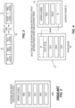
- Fig. 1 illustrates a wireless communication network 10 configured to provide communication services to any number of wireless communication devices 12, where only two such devices 12-1 and 12-2 are shown by way of example.
- the reference number "12" is used herein, for both singular and plural reference to any given device, or devices. The same usage applies with respect to any other "base” reference number where suffixing is used herein.
- the network 10 communicatively couples the individual devices 12 to one or more operator, OP, Internet Protocol, IP, services and/or external networks 14, such as the Internet and may provide for inter-device communications within the network 10.
- the network 10 includes a Radio Access Network, RAN 16, and a Core Network, CN 18.
- the RAN 16 includes a radio node 20 and a gateway node 22.
- the gateway node 22 is configured to control the radio node 20 and to provide communicative coupling to the CN 18.
- the radio node 20 is a home base station or other small-cell device that provides radio coverage in a corresponding radio cell or cells 24, which may have a limited coverage area, such as a low-power cell intended to encompass a single residence or other structure.
- the radio node 20 may provide more than one cell 24, e.g., by using different carrier frequencies, using different frequency subbands, using Time Division Multiplexing, TDM, etc.
- the network 10 may include any number of radio nodes 20, e.g., each at different locations within a broader geographic area. Further, the network 10 may include a gateway node 22 for each such radio node 20, or may have one gateway node 22 for subsets or groups of radio nodes 20. In one or more embodiments, it is contemplated to control potentially large numbers of radio nodes 20 via one gateway node 22.
- the network 10 may include other entities not illustrated or described, as will be understood by those of ordinary skill in the wireless communication arts.
- the network 10 comprises a Long Term Evolution, LTE, or LTE-Advanced network, configuring according to the applicable technical specifications promulgated by the Third Generation Partnership Project, 3GPP. Consequently, the network 10 includes a variety of nodes or other entities associated with such networks, including Mobility Management Entities or MMEs in the CN 18, along with a Packet Data Gateway Nodes or PDGN, providing a packet data interface between the CN 18 and the external network(s) 14.
- MME Mobility Management Entities
- PDGN Packet Data Gateway Nodes
- the radio node 20 is implemented as a LTE Home eNB, HeNB, or as some other type of radio base station, it will be understood as comprising a mix of signal processing and control circuitry, along with supporting radio transceiver circuitry.
- the radio node 20 includes first and second communication interfaces 30-1 and 30-2-generally referred to as "communication interfaces 30"-along with processing circuitry 32 that is operatively associated with the communication interfaces 30.
- the processing circuitry 32 comprises fixed circuitry, programmed circuitry, or a combination of fixed and programmed circuitry.
- the processing circuitry 32 is at least partly implemented using programmed circuitry and comprises, for example, one or more processors 34, such as one or more microprocessors, Digital Signal Processors or DSPs, Application Specific Integrated Circuits or ASICs, Field Programmable Gate Arrays or FPGAs, or other digital processing circuitry.
- the processing circuitry 32 includes or is associated with one or more types of computer-readable media-"STORAGE 36" in the figure-such as one or more types of memory circuits such as FLASH, EEPROM, SRAM, DRAM, etc.
- the storage 36 comprises hard disk storage, Solid State Disk, SSD, storage, etc.
- the storage 36 provides both working memory and longer-term storage.
- the storage 36 provides non-transitory storage for a computer program 38 and one or more items of configuration data 40.
- non-transitory does not necessarily mean permanent or unchanging storage but does means storage of at least some persistence-i.e., holding information for subsequent retrieval.
- the computer program 38 which may comprise a number of related or supporting programs, comprises program instructions that, when executed by the one or more processors 34 implement the processing circuitry 32 according to the configuration examples described herein.
- one or more general-purpose processing circuits within the radio node 20 are specially adapted to carry out the teachings herein, based on their execution of the computer program instructions comprising the computer program 38.
- the radio node 20 is configured to provide radio coverage in one or more cells 24, and the first communication interface 30-1 is configured for communicating with wireless devices 12 operating in any of the one or more cells 24.
- the communication interface 30-1 is configured for transmitting and receiving radiofrequency signals according to the air interface protocols and signal structure adopted for the air interface between the radio node 20 and the devices 12.
- the communication interface 30-1 includes one or more radiofrequency transmitters and receivers, and associated protocol processing circuitry that is adapted to support the uplink and downlink air interfaces implemented within the network 10.
- the radio node 20 further includes a second communication interface 30-2 configured to communicatively couple the radio node 20 to its controlling gateway node 22, which in turn is coupled to the CN 18.
- the second communication interface 30-2 may comprise a wired or wireless interface, e.g., a LAN or microwave-based interface, and shall be understood as providing physical-layer circuitry adapted for sending and receiving signals over the involved transmission medium, along with corresponding circuitry for protocol processing, as needed for communicating with the gateway node 22.
- the gateway node 22 will be understood as comprising a mix of signal processing and control circuitry, along with supporting communication interfaces-i.e., communication interface circuits.
- the gateway node 22 includes first and second communication interfaces 50-1 and 50-2-generally referred to as "communication interfaces 50"-along with processing circuitry 52 that is operatively associated with the communication interfaces 50.
- the processing circuitry 52 comprises fixed circuitry, programmed circuitry, or a combination of fixed and programmed circuitry.
- the processing circuitry 52 is at least partly implemented using programmed circuitry and comprises, for example, one or more processors 54, such as one or more microprocessors, Digital Signal Processors or DSPs, Application Specific Integrated Circuits or ASICs, Field Programmable Gate Arrays or FPGAs, or other digital processing circuitry.
- the processing circuitry 52 includes or is associated with one or more types of computer-readable media-"STORAGE 56" in the figure-such as one or more types of memory circuits such as FLASH, EEPROM, SRAM, DRAM, etc.
- the storage 56 comprises hard disk storage, Solid State Disk, SSD, storage, etc.
- the storage 56 provides both working memory and longer-term storage.
- the storage 56 provides non-transitory storage for a computer program 58 and one or more items of configuration data 60.
- the term non-transitory does not necessarily mean permanent or unchanging storage, but does means storage of at least some persistence.
- the computer program 58 which may comprise a number of related or supporting programs, comprises program instructions that, when executed by the one or more processors 54 implement the processing circuitry 52 according to the configuration examples described herein.
- one or more general-purpose processing circuits within the gateway node 22 are specially adapted to carry out the teachings herein, based on their execution of the computer program instructions comprising the computer program 58.
- the first communication interface 50-1 is configured for communicating with the radio node 20, which is controlled by the gateway node 22, and the second communication interface 50-2 is configured for communicating with one or more core network nodes-not individually depicted in Fig. 1 -in the CN 18 of the network 10.
- Fig. 2 illustrates a known radio protocol stack used in LTE. It will be appreciated that a complementary or mirror copy of the illustrated stack is conventionally implemented in each of the involved protocol endpoints-e.g., in a wireless device and in its serving base station. In the context of these teachings, the "network side" radio protocol stack is split between the radio node 20 and its controlling gateway node 22.
- Fig. 3 illustrates an example split-stack arrangement.
- a radio protocol stack 70 is split.
- the upper portion 72 of the radio protocol stack 70 resides in the gateway node 22 while a lower portion 74 of the radio protocol stack 70 resides in the radio node 22.
- the upper portion 72 includes a Packet Data Convergence Protocol, PDCP, layer and a Radio Resource Control, RRC, layer.
- the PDCP layer is "below" the RRC layer.
- the lower portion 74 of the radio protocol stack 70 includes a Radio Link Control, RLC, layer, a Medium Access Control, MAC, protocol layer below the RLC protocol layer, and a Physical, PHY, protocol layer below the MAC protocol layer.
- Fig. 4 provides further example details.
- a "PDCP stub" may be implemented in the lower portion 74 of the radio protocol stack 70, to account for the fact that the illustrated split lies at the RLC-to-PDCP logical interface.
- the intra-stack IP link 26 / IP session(s) 28 communicatively couples the RRC and PDCP layers at the gateway node 22 to the RLC protocol layer at the radio node 20.
- one or more IP sessions 28 are used to send SDUs from the RRC/PDCP layers RLC layer to the RLC layer over the intra-stack IP link 26 in the downlink direction and vice-versa in the uplink direction.
- the processing circuitry 52 of the gateway node 22 is operatively associated with the first and second communication interfaces 50 and is configured to determine that data is available for sending to a wireless device 12 that accesses the network 10 via a radio cell 24 provided by the radio node 20, where the radio node 20 is coupled to the CN 18 of the network 10 via the gateway node 22.
- the processing circuitry 52 is further configured to generate service data units corresponding to the data, based on processing the data according to an upper portion 72 of a radio protocol stack 70.
- the radio protocol stack 70 is split between the gateway node 22, which implements the upper portion 72 of the radio protocol stack 70, and the radio node 20, which implements the lower portion 74 of the radio protocol stack 70.
- the radio protocol stack 70 is the network-side stack and that the wireless device 12 implements a complementary device-side radio protocol stack having peer entities corresponding to the protocol entities seen in the network-side stack 70.
- the processing circuitry 52 of the gateway node 22 is configured to establish an IP session 28 towards the radio node 20, via an intra-stack IP link 26 that communicatively couples the upper portion 72 of the radio protocol stack 70 at the gateway node 22 with the lower portion 74 of the radio protocol stack 70 at the radio node 20.
- this IP session is distinct from and transparent to any IP sessions that may be running at the "applications" layer between the wireless device 12 and an application server in the OP services / external networks 14.
- the IP session 28 is transparent to the end-to-end communications session(s) between the wireless device 12 and any end-point accesses via the network 10, and is used purely to connect the upper portion 72 of the network-side radio protocol stack 70 at the gateway node 22 to the lower portion 74 of the network-side radio protocol stack 70 at the radio node 20.
- the IP session 28 is mapped to a radio bearer to be used for conveying the data to the wireless device 12 via an air interface of the radio cell 24, and the processing circuitry 52 is configured to encapsulate the service data units in one or more IP packets, according to IP session parameters associated with the IP session 28, and send the IP packets to the radio node 20 via the IP session 28, for de-encapsulation and recovery of the service data units, for subsequent processing by the radio node 20 according to the remaining, lower portion 74 of the radio protocol stack 70.
- Complementary processing and functions at the gateway node 22 and at the radio node 20 provide for the transfer of uplink data and signaling from the wireless device over one or more IP sessions 28 on the intra-stack IP link 26. That is, downlink data towards the wireless device 12 is processed at the gateway node 22 according to the protocol layers implemented in the upper portion 72 of the radio protocol stack 70, and is encapsulated as IP traffic for conveyance over an IP session 28 supported via the intra-stack IP link 26.
- the radio node 20 receives the encapsulated data and de-encapsulates it for processing according to the protocol layers implemented in the lower portion 74 of the radio protocol stack 70.
- uplink data-traffic or signaling-from the wireless device 12 is received by the radio node 20 and processed in the uplink direction according to the lower portion 74 of the radio protocol stack.
- the processed data is sent from the radio node 20 to the gateway node 22 as IP packets in an IP session 28 on the intra-stack IP link 26.
- the gateway node 22 extracts the data encapsulated in the IP packets and continues processing that data in the uplink direction, according to the protocol layers implemented in the upper portion 72 of the radio protocol stack 70.
- the processing circuitry 52 is configured to establish the IP session 28 using a User Datagram Protocol, UDP, when the radio bearer is a data radio bearer, and the wireless device 12 is operating in a Radio Link Control, RLC, Unacknowledged Mode, UM.
- the processing circuitry 52 is further configured to establish the IP session 28 using a Transmission Control Protocol, TCP, when the radio bearer is a data radio bearer and the wireless device 12 is operating in a RLC Acknowledged Mode, AM, or in a RLC Transparent Mode, TM.
- TCP Transmission Control Protocol
- the processing circuitry 52 is configured to establish the IP session 28 using a Transport Layer Security, TLS, protocol, when the radio bearer is a signaling radio bearer, for transmitting Broadcast Control Channel, BCCH, or Paging Control Channel, PCCH, signaling. TLS is also used for SRB0 and SRB1, after AS. Further, in at least some embodiments, the IP session 28 is mapped uniquely for the radio bearer and the wireless device 12, or is mapped according to a unique flow label assigned to the radio bearer, or is mapped to a unique flow label assigned to the wireless device 12.
- TLS Transport Layer Security
- the IP session 28 is mapped uniquely for the radio bearer and the wireless device 12, or is mapped according to a unique flow label assigned to the radio bearer, or is mapped to a unique flow label assigned to the wireless device 12.
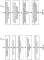
- Fig. 5 illustrates a method 500 of operation in a gateway node 22 that is coupled to a CN 18 of a network 10.
- Fig. 5 focuses on downlink processing and the method 500 includes determining (Block 502) that data is available for sending to a wireless device 12 that accesses the wireless communication network 10 via a radio cell 24 provided by a radio node 20 that is coupled to the CN 18 of the wireless communication network 10 via the gateway node 22.
- the method 500 further includes generating (Block 504) service data units corresponding to the data, based on processing the data according to an upper portion 72 of a radio protocol stack 70, wherein the radio protocol stack 70 is split between the gateway node 22, which implements the upper portion 72 of the radio protocol stack, and the radio node 20, which implements a remaining, lower portion 74 of the radio protocol stack 70.
- the method 500 includes establishing (Block 506) an IP session 28 towards the radio node 20, via an intra-stack IP link 26 that communicatively couples the upper portion 72 of the radio protocol stack 70 at the gateway node 22 with the lower portion 74 of the radio protocol stack 70 at the radio node 20.
- the IP session 28 is mapped to a radio bearer to be used for conveying the data to the wireless device 12 via an air interface of the radio cell 24, and the method 500 includes encapsulating (Block 508) the service data units in one or more IP packets, according to IP session parameters associated with the IP session 28, and sending (Block 510) the IP packets to the radio node 20 via the IP session 28, for de-encapsulation and recovery of the service data units, for subsequent processing by the radio node 20 according to the remaining, lower portion 74 of the radio protocol stack 70.
- the IP link 26 in one embodiment comprises an IP Version 6, IPv6, link.
- IP link 26 be implemented as an IPv4 link and in operation, the gateway node 22 may support IP sessions 28 based on both IPv4 and IPv6. For example, a given radio node 20 may not support IPv6, while another radio node 20 does support IPv6.
- Fig. 6 illustrates a method 600 in a radio node 20, corresponding to the gateway method 500.
- the radio node 20 is configured for operation in the network 10 and is particularly configured for being controlled by the gateway node 22.
- the method 600 includes establishing (Block 602) a radio bearer under control of a gateway node 22, for communicating with a wireless device 12 and establishing (Block 604) an IP session 28 with the gateway node 22, via an intra-stack IP link 26 between the radio node 20 and the controlling gateway node 22.
- this IP link 26 is for connecting the upper and lower portions 72 and 74 of the split radio protocol stack 70, and should not be confused with end-to-end IP sessions/links between the wireless device 12 and any "application" layer servers or systems.
- the method 600 further includes receiving (Block 606) one or more IP packets via the IP session 28 and de-encapsulating the received IP packets to recover the data targeted to the wireless device 12. More particularly, the de-encapsulation involves de-encapsulating the IP packets to recover the SDUs incoming from the protocol layer operating in the gateway node 22 at the point where the radio protocol stack 70 is split between the gateway node 22 and the radio node 20. Correspondingly, the method 600 further includes inputting (Block 608) the de-encapsulated data into the remaining, lower-portion 74 of the radio protocol stack 70, as implemented at the radio node 20, for processing and sending to the wireless device 12 over the air interface.
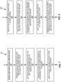
- Figs. 7 and 8 illustrate substantially similar processing as set forth in Figs. 5 and 6 , but are presented in the context of uplink processing.
- the method 700 of Fig. 7 depicts radio node processing and includes receiving (Block 702) user traffic from a wireless device 12.
- the method 700 further includes generating (Block 704) SDU(s) from the received user traffic, via the lower portion 74 of the radio protocol stack 70, and mapping (Block 706) the radio bearer associated with the SDU(s) to an IP session 28 on the intra-stack IP link 26.
- Processing continues with the radio node 20 encapsulating (Block 708) the SDU(s) into one or more IP packets, in accordance with the mapped/Identified IP session 28, and sending (Block 710) the IP packet(s) towards the gateway node 22 over the intra-stack IP link 26.
- Fig. 8 illustrates a corresponding method 800 as carried out by the gateway node 22.
- the method 800 includes receiving (Block 802) an IP packet from the radio node 20 in an IP session 28 on the intra-stack IP link 26, and mapping (Block 804) the IP session 28 to a radio bearer, according to session/bearer mapping known at the gateway node 22, e.g., from connection setup/establishment processing. Processing continues with the gateway node 22 de-encapsulating (Block 806) the SDU(s) contained in the IP packet and inputting (Block 808) the SDU(s) into the upper portion 72 of the radio protocol stack. The method 800 continues with the gateway node 22 sending (Block 810) the data generated from processing the SDU(s) in the upper portion 72 of the radio protocol stack 70 on to the core network for higher-layer processing.
- a SDU output from the "top" of the lower portion 74 of the radio protocol stack 70 is encapsulated in an IP packet for transport over the intra-stack IP link 26, in the IP session 28 to which the involved radio bearer is mapped.
- the SDU is extracted from the IP packet and passed into the "bottom" of the upper portion 72 of the radio protocol stack 70, for completion of the overall protocol processing associated with the radio protocol stack 70 in the uplink direction.
- the converse is true in the downlink direction, i.e., SDUs emerging from the bottom of the upper portion 72 of the radio protocol stack 70 are encapsulated as IP packets and transported in a mapped IP session 28 over the intra-stack IP link 26.
- the radio node 20 de-encapsulates those IP packets to recover the SDUs, which are then input to the top of the lower portion 74 of the radio protocol stack 70, for completion of the overall stack processing in the downlink direction.
- the "bottom" of the upper portion 72 is taken as the stack layer at the gateway node 22 that is exposed to the split.
- the "top” of the lower portion 74 is taken as the stack layer at the radio node 20 that is exposed to the split.
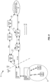
- Fig. 9 illustrates an example embodiment in the context of a LTE network, wherein the CN 18 includes serving gateway, S-GW 80, coupled to the gateway node 22 via a S1-UE interface, and a MME 82 coupled to the gateway node 22 via a S1-MME interface.
- the S-GW 80 and MME are communicatively coupled via a S11 interface, and the S-GW 80 is further communicatively coupled to a Packet Gateway, P-GW 84, which provides the packet-routing interface, SGi, into and out of the network 10.
- P-GW 84 Packet Gateway
- the MME 82 communicatively couples to a Home Subscriber Server, HSS 86, via an S6a interface, and the HSS 86 couples to a Policy and Charging Rules Function, PCRF 88, which is also coupled to the P-GW 84.
- PCRF 88 Policy and Charging Rules Function
- dashed connection lines are used to illustrate Control Plane, CP, signaling
- solid connection lines are used to illustrate User Plane, UP, signaling.
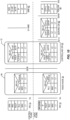
- Fig. 10 illustrates an example splitting of the radio protocol stack 70 between the radio node 20 and the gateway node 22, in the context of the LTE network example of Fig. 9 .
- Fig. 10 illustrates the further supporting protocol stacks used at the various other CN nodes seen in Fig. 9 and particularly highlights the IP link 26/IP session 28 used to link the lower portion 74 of the split radio protocol stack 70, as implemented in the radio node 20, with the upper portion 72 of the stack 70, as implemented in the gateway node 22. It will be appreciated that there may be any number of split-stack "instances" implemented between the gateway node 22 and the radio node 20, e.g., for simultaneously supporting multiple wireless devices 12.
- mapping of radio bearer, RB, traffic, e.g., PDCP PDUs, to IP sessions 28 provides for flexible connectivity between a gateway node 22 and any number of controlled radio nodes 20.
- the proposed RB-to-IP mapping schemes provide a scalable solution that supports potentially large numbers of radio nodes 20 with respect to a controlling gateway node 22.
- mapping scheme(s) presented herein provide radio bearer traffic granularity and a sound, robust traffic isolation solution upon which various network use-cases become more easily deployable by the network operator.
- Example use cases include bearer-based or device-based routing policy deployment, for efficiently routing device traffic over the IP connection interconnecting the split stack 70, e.g., using IPv6 flow labels.
- bearer-based and/or device-based access control security policy deployment such as where firewalling parameters or policy settings are based on the identities of the wireless devices 12 being supported via the split-stack arrangement.
- Further examples include bearer-based and/or device-based Quality-of-Server, QoS, policy deployment, data packet inspection at the gateway node 22 on a per device 12 and a per radio node 20 basis, and lawful interception techniques, which typically requires per device discrimination.
- the teachings herein further provide for the use of IP service discovery for dynamic configuration of the radio node 20, e.g. IPv6 address auto- configuration-stateless address auto configuration or SLAAC-as well as dynamic discovery of the gateway node 22 by each radio node 20 to be controlled by the gateway node 22.
- the teachings herein further provide for the use of Transport Layer Security, TLS, encryption to secure BCCH, PCCH, SRB0 and SRB1 traffic, which is not PDCP-ciphered.
- SRB0" and “SRB1” denotes Signaling Radio Bearer 0 and Signaling Radio Bearer 1, respectively.
- the SRB0 and SRB1 are used for the transfer of RRC and Non-Access Stratum signaling messages.
- RRC messages go between the wireless device 12 and the radio node 20 and NAS messages go between the wireless device 12 and the MME 82.
- the teachings herein enable the use of TCP for window-based flow control of RLC traffic in the AM mode.
- the radio node 20 provides the RLC/MAC/PHY layers of the radio protocol stack 70, i.e., the lower portion 74 of the split stack 70 at the radio node 20 includes the RLC, MAC, and PHY layers.
- the gateway node 22 provides centralized RRC and PDCP functions, which are managed by the involved network operator and are connected to any number of radio nodes 20.
- the gateway node 22 provides centralized radio resource control for multiple radio nodes 20.
- the gateway node 22 further provides the mapping between the GTP-U TEID-to-IP sessions for Data Radio Bearers, DRBs, as well as the mapping of RRC contexts-to-IP sessions for Signaling Radio Bearers, SRBs, based on the information supplied by each such radio node 20.
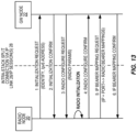
- Fig. 13 illustrates a call flow diagram covering processing that follows the establishment of a secure connection between a radio node 20 and its supporting gateway node 22.
- the radio node 20 After establishing a secure channel, the radio node 20 connects to the gateway node 22 to initiate configuration.
- the gateway node 22 will then provide the radio initialization parameters, such as radio frequency bands, bandwidth, access schemes, antenna technology, physical channel configurations, etc., for the radio node 20.
- the radio node 20 sends the set of mappings between each radio bearer and the IP address plus the port and/or IPv6 flow label combination that it will use for traffic on that specific bearer, with respect to the IP link 26.
- IPv6 links are used to transport data between the radio node 20 and the gateway node 22 for the IP link 26 supporting the stack split
- the first mapping scheme presented below is also applicable to IPv4 links. It is assumed that there is a single PDU per IP packet, and all messages are sent in network byte order. All contemplated schemes consider UDP for bearers configured in RLC UM mode and TCP for RLC AM and TM.
- a second mapping option contemplated herein there is a unique IPv6 flow label per bearer type. As compared to the first mapping scheme, the difference is that flow isolation is achieved by using a different IPv6 flow label per radio bearer type. This second scheme allows for improved packet switching based on flow label or bearer type.
- a third mapping option there is a unique IPv6 flow label per wireless device 12.
- the difference with this third mapping scheme is that flow isolation is achieved by using a different IPv6 flow label per wireless device 12, which is identified with a C-RNTI-like ID. If the flow labels are exchanged on demand, for example, upon initial attachment of a wireless device 12 to the radio node 20, the IPv6 flow labels could embed the C-RNTI of the attaching wireless device 12.
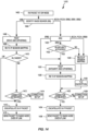
- Fig. 14 is a logic flow diagram illustrating another embodiment of a method 1400 of processing at a gateway node 22 that is configured for operation in a network 10, and for controlling a radio node 20 that is configured to communicatively couple one or more wireless devices 12 to the network 10 via a cell 24 provided by the radio node 20.
- the method 1400 focuses on a downlink example and begins with receiving a packet at the gateway node 22 for a given wireless device 12 (Block 1402). Processing continues with identifying the radio bearer or radio bearer type to be used for conveying the received packet (Block 1404).
- the received packet is user traffic, it is associated with a DRB and processing continues in Block 1406, with performing Robust Header Compression, ROHC, and ciphering at the PDCP layer of the radio protocol stack 70.
- the PDCP layer resides in the gateway node 22.
- the involved DRB is mapped to an IP session 28 (Block 1408) that provides the intra-stack connection between the split entities of radio protocol stack 70, and the RLC mode is determined (Block 1410).
- the method 1400 includes checking whether a connection to the wireless device 12 has been established (Block 1412) and performing connection setup (Block 1414) if not.
- processing continues with encapsulating (Block 1416) the received user-traffic packet in an IP packet for conveyance (Block 1418) to the radio node 20 via the IP session 28 supported by the IP link 26 that interconnects the lower portion 74 of the split radio protocol stack 70 in the radio node 20 with the upper portion 72 of the split radio protocol stack 70 in the gateway node 22.
- the encapsulation occurs here for purposes of conveying the packet between the split entities of the radio protocol stack 70, as split between the gateway node 22 and the radio node 20, and is unrelated to any IP running at protocol layers above the split radio protocol stack 70. It will also be appreciated that a corresponding de-encapsulation, therefore, occurs within the lower portion 74 of the radio protocol stack 70 at the radio node 20.
- this usage of IP conveyance is transparent to higher-layer protocol endpoints running at the wireless device 12 and, e.g., at the P-GW 84 or at some server external to the network 10, and is operative only with respect to interconnecting the entities within the radio protocol stack 70 that are exposed to the split between the radio node 20 and the gateway node 22.
- RRC processing is performed at Block 1420 and, for SRB1 signaling, processing includes determining whether AS Security-a LTE security protocol associated with RRC signaling-is active (Block 1422). If AS Security is not active, it is contemplated herein to advantageously apply TLS, and processing in this case thus continues with RB-to-IP-Session mapping (Block 1428), for the IP link 26, and TLS encryption of the received packet (Block 1430). TLS could be used for the duration of the SRB1 traffic, but switching after AS is another option.
- the PDCP layer processing includes encryption of the packet, and thus processing can continue from Block 1420 or Block 1422 with PDCP processing (Block 1424) and RB-to-IP-Session mapping for the IP link 26 (Block 1426).
- processing continues with determining whether a connection to the wireless device 12 has been established (Block 1432) and, if so, performing IP encapsulation of the packet for conveyance over the IP link 26 in the mapped IP session 28 (Blocks 1434 and 1436). If the connection has not already been setup, the connection is setup at Block 1438 (NO from Block 1432), and then the encapsulation and conveyance operations in Blocks 1434 and 1436 are carried out.
Landscapes
- Engineering & Computer Science (AREA)
- Computer Networks & Wireless Communication (AREA)
- Signal Processing (AREA)
- Computer Security & Cryptography (AREA)
- Mobile Radio Communication Systems (AREA)
Claims (8)
- Verfahren zum Betreiben in einem Gateway-Knoten (22), der mit einem Kernnetz (18) eines drahtlosen Kommunikationsnetzes (10) gekoppelt ist, wobei das Verfahren Folgendes umfasst:Bestimmen (502), dass Daten zum Senden an eine drahtlose Vorrichtung (12) verfügbar sind, die über eine Funkzelle (24) auf das drahtlose Kommunikationsnetz (10) zugreift, die durch einen Funkknoten (20), der über den Gateway-Knoten (22) mit dem Kernnetz (18) des drahtlosen Kommunikationsnetzes (10) gekoppelt ist, bereitgestellt wird;Erzeugen (504) von Dienstdateneinheiten, die den Daten entsprechen, basierend auf Verarbeiten der Daten gemäß einem oberen Abschnitt (72) eines Funkprotokollstapels (70), wobei der Funkprotokollstapel (70) zwischen dem Gateway-Knoten (22), der den oberen Abschnitt (72) des Funkprotokollstapels umsetzt, und dem Funkknoten (20), der einen verbleibenden, unteren Abschnitt (74) des Funkprotokollstapels (70) umsetzt, aufgeteilt ist;Herstellen einer Intra-Stapel-Internetprotokollverknüpfung, Intra-Stapel-IP-Verknüpfung (26), mit dem Funkknoten (20), die den oberen Abschnitt (72) des Funkprotokollstapels (70) an dem Gateway-Knoten (22) kommunikativ mit dem unteren Abschnitt (74) des Funkprotokollstapels (70) an dem Funkknoten (20) koppelt, undSenden von Dienstdateneinheiten, SDUs, von dem oberen Abschnitt (72) des Funkprotokollstapels (70), wie in dem Gateway-Knoten (22) umgesetzt, an den unteren Abschnitt (74) des Funkprotokollstapels (70), wie in dem Funkknoten (20) umgesetzt, über die Intra-Stapel-IP-Verknüpfung (26),wobei der Funkprotokollstapel (70) als den oberen Abschnitt (72) eine Paketdatenkonvergenzprotokollschicht, PDCP-Schicht, und eine Funkressourcensteuerungsschicht, RRC-Schicht, beinhaltet und als den unteren Abschnitt (74) eine Funkverknüpfungssteuerungsprotokollschicht, RLC-Protokollschicht, unter der PDCP-Schicht, eine Medienzugriffssteuerungsprotokollschicht, MAC-Protokollschicht, unter der RLC-Protokollschicht und eine physische Protokollschicht, PHY-Protokollschicht, unter der MAC-Protokollschicht beinhaltet, unddadurch gekennzeichnet, dassdie Intra-Stapel-IP-Verknüpfung (22) den Gateway-Knoten (22) kommunikativ mit der RLC-Protokollschicht an dem Funkknoten (20) koppelt.
- Verfahren nach Anspruch 1, wobei die Intra-Stapel-IP-Verknüpfung (26) eine IP-Verknüpfung gemäß Version 6, IPv6-Verknüpfung, umfasst.
- Verfahren nach Anspruch 1 oder 2, ferner umfassend:zum Liefern von Daten an die drahtlose Vorrichtung (12) über einen Datenfunkträger zwischen dem Funkknoten (20) und der drahtlosen Vorrichtung (12), wenn die drahtlose Vorrichtung (12) in einem unbestätigten Modus, UM, der Funkverknüpfungssteuerung, RLC, betrieben wird, Herstellen einer IP-Sitzung (28) über die Intra-Stapel-IP-Verknüpfung (26) unter Verwendung eines Benutzerdatagrammprotokolls, UDP;zum Liefern von Daten an die drahtlose Vorrichtung (12) über einen Datenfunkträger zwischen dem Funkknoten (20) und der drahtlosen Vorrichtung (12), wenn die drahtlose Vorrichtung (12) in einem bestätigten Modus, AM, der RLC oder in einem transparenten Modus, TM, der RLC betrieben wird, Herstellen einer IP-Sitzung (28) über die Intra-Stapel-IP-Verknüpfung (26) unter Verwendung eines Transportsteuerungsprotokolls, TCP; undzum Übertragen einer Rundrufsteuerungskanalsignalisierung, BCCH-Signalisierung, oder einer Paging-Steuerungskanalsignalisierung, PCCH-Signalisierung, für die drahtlose Vorrichtung (12) über einen Signalisierungsfunkträger an dem Funkknoten (20), Herstellen einer IP-Sitzung (28) über die Intra-Stapel-IP-Verknüpfung (26) unter Verwendung eines Transportschichtsicherheitsprotokolls, TLS-Protokolls.
- Verfahren nach einem der Ansprüche 1 bis 3, wobei die SDUs, die über die Intra-Stapel-IP-Verknüpfung (26) gesendet werden, in einer oder mehreren IP-Sitzungen (28) gesendet werden, die eindeutig für die drahtlose Vorrichtung (12) zugeordnet sind.
- Gateway-Knoten (22), der zum Betreiben in einem drahtlosen Kommunikationsnetz (10) konfiguriert ist und Folgendes umfasst:eine erste Kommunikationsschnittstelle, die zum Kommunizieren mit einem Funkknoten (20) konfiguriert ist, der durch den Gateway-Knoten (22) zu steuern ist;eine zweite Kommunikationsschnittstelle, die zum Kommunizieren mit einem oder mehreren Kernnetzknoten in einem Kernnetz (18) des drahtlosen Kommunikationsnetzes (10) konfiguriert ist; undeinen Verarbeitungsschaltkreis, der betriebswirksam mit der ersten und der zweiten Kommunikationsschnittstelle assoziiert und zu Folgendem konfiguriert ist:Bestimmen, dass Daten zum Senden an eine drahtlose Vorrichtung (12) verfügbar sind, die über eine Funkzelle (24), die durch den Funkknoten (20) bereitgestellt wird, auf das drahtlose Kommunikationsnetz (10) zugreift, wobei der Funkknoten (20) über den Gateway-Knoten (22) mit dem Kernnetz (18) des drahtlosen Kommunikationsnetzes (10) gekoppelt ist;Erzeugen von Dienstdateneinheiten, die den Daten entsprechen, basierend auf Verarbeiten der Daten gemäß einem oberen Abschnitt (72) eines Funkprotokollstapels (70), wobei der Funkprotokollstapel (70) zwischen dem Gateway-Knoten (22), der den oberen Abschnitt (72) des Funkprotokollstapels umsetzt, und dem Funkknoten (20), der einen verbleibenden, unteren Abschnitt (74) des Funkprotokollstapels (70) umsetzt, aufgeteilt ist;Herstellen einer Intra-Stapel-Internetprotokollverknüpfung, Intra-Stapel-IP-Verknüpfung (26), mit dem Funkknoten (20), die den oberen Abschnitt (72) des Funkprotokollstapels (70) an dem Gateway-Knoten (22) kommunikativ mit dem unteren Abschnitt (74) des Funkprotokollstapels (70) an dem Funkknoten (20) koppelt, undSenden von Dienstdateneinheiten, SDUs, von dem oberen Abschnitt (72) des Funkprotokollstapels (70), wie in dem Gateway-Knoten (22) umgesetzt, an den unteren Abschnitt (74) des Funkprotokollstapels (70), wie in dem Funkknoten (20) umgesetzt, über die Intra-Stapel-IP-Verknüpfung (26),wobei der Funkprotokollstapel (70) als den oberen Abschnitt (72) eine Paketdatenkonvergenzprotokollschicht, PDCP-Schicht, und eine Funkressourcensteuerungsschicht, RRC-Schicht, beinhaltet und als den unteren Abschnitt (74) eine Funkverknüpfungssteuerungsprotokollschicht, RLC-Protokollschicht, unter der PDCP-Schicht, eine Medienzugriffssteuerungsprotokollschicht, MAC-Protokollschicht, unter der RLC-Protokollschicht und eine physische Protokollschicht, PHY-Protokollschicht, unter der MAC-Protokollschicht beinhaltet, unddadurch gekennzeichnet, dassdie Intra-Stapel-IP-Verknüpfung (26) den Gateway-Knoten (22) kommunikativ mit der RLC-Protokollschicht an dem Funkknoten (20) koppelt.
- Gateway nach Anspruch 5, wobei die Intra-Stapel-IP-Verknüpfung eine IP-Verknüpfung gemäß Version 6, IPv6-Verknüpfung, umfasst.
- Gateway-Knoten (22) nach Anspruch 5 oder 6, wobei der Verarbeitungsschaltkreis zu Folgendem konfiguriert ist:zum Liefern von Daten an die drahtlose Vorrichtung (12) über einen Datenfunkträger zwischen dem Funkknoten (20) und der drahtlosen Vorrichtung (12), wenn die drahtlose Vorrichtung (12) in einem unbestätigten Modus, UM, der Funkverknüpfungssteuerung, RLC, betrieben wird, Herstellen einer IP-Sitzung (28) über die Intra-Stapel-IP-Verknüpfung (26) unter Verwendung eines Benutzerdatagrammprotokolls, UDP;zum Liefern von Daten an die drahtlose Vorrichtung (12) über einen Datenfunkträger zwischen dem Funkknoten (20) und der drahtlosen Vorrichtung (12), wenn die drahtlose Vorrichtung (12) in einem bestätigten Modus, AM, der RLC oder in einem transparenten Modus, TM, der RLC betrieben wird, Herstellen einer IP-Sitzung (28) über die Intra-Stapel-IP-Verknüpfung (26) unter Verwendung eines Transportsteuerungsprotokolls, TCP; undzum Übertragen einer Rundrufsteuerungskanalsignalisierung, BCCH-Signalisierung, oder einer Paging-Steuerungskanalsignalisierung, PCCH-Signalisierung, für die drahtlose Vorrichtung (12) über einen Signalisierungsfunkträger an dem Funkknoten (20), Herstellen einer IP-Sitzung (28) über die Intra-Stapel-IP-Verknüpfung (26) unter Verwendung eines Transportschichtsicherheitsprotokolls, TLS-Protokolls.
- Gateway-Knoten (22) nach einem der Ansprüche 5 bis 7, wobei die SDUs, die über die Intra-Stapel-IP-Verknüpfung (26) gesendet werden, in einer oder mehreren IP-Sitzungen gesendet werden, die eindeutig für die drahtlose Vorrichtung (12) zugeordnet sind.
Priority Applications (1)
| Application Number | Priority Date | Filing Date | Title |
|---|---|---|---|
| EP19207124.9A EP3657901B1 (de) | 2015-09-21 | 2015-09-21 | Verfahren und vorrichtung zum ip-transport zwischen einem funkknoten und einem steuernden gateway mit funkfunktionen |
Applications Claiming Priority (3)
| Application Number | Priority Date | Filing Date | Title |
|---|---|---|---|
| EP19207124.9A EP3657901B1 (de) | 2015-09-21 | 2015-09-21 | Verfahren und vorrichtung zum ip-transport zwischen einem funkknoten und einem steuernden gateway mit funkfunktionen |
| PCT/US2015/051226 WO2017052496A1 (en) | 2015-09-21 | 2015-09-21 | Method and apparatus for ip transport between a radio node and a controlling gateway with radio functions |
| EP15772170.5A EP3354114B1 (de) | 2015-09-21 | 2015-09-21 | Verfahren und vorrichtung für einen funkknoten und einen steuerungsgateway |
Related Parent Applications (1)
| Application Number | Title | Priority Date | Filing Date |
|---|---|---|---|
| EP15772170.5A Division EP3354114B1 (de) | 2015-09-21 | 2015-09-21 | Verfahren und vorrichtung für einen funkknoten und einen steuerungsgateway |
Publications (3)
| Publication Number | Publication Date |
|---|---|
| EP3657901A1 EP3657901A1 (de) | 2020-05-27 |
| EP3657901B1 true EP3657901B1 (de) | 2025-03-05 |
| EP3657901C0 EP3657901C0 (de) | 2025-03-05 |
Family
ID=54238625
Family Applications (2)
| Application Number | Title | Priority Date | Filing Date |
|---|---|---|---|
| EP15772170.5A Active EP3354114B1 (de) | 2015-09-21 | 2015-09-21 | Verfahren und vorrichtung für einen funkknoten und einen steuerungsgateway |
| EP19207124.9A Active EP3657901B1 (de) | 2015-09-21 | 2015-09-21 | Verfahren und vorrichtung zum ip-transport zwischen einem funkknoten und einem steuernden gateway mit funkfunktionen |
Family Applications Before (1)
| Application Number | Title | Priority Date | Filing Date |
|---|---|---|---|
| EP15772170.5A Active EP3354114B1 (de) | 2015-09-21 | 2015-09-21 | Verfahren und vorrichtung für einen funkknoten und einen steuerungsgateway |
Country Status (3)
| Country | Link |
|---|---|
| US (3) | US10129914B2 (de) |
| EP (2) | EP3354114B1 (de) |
| WO (1) | WO2017052496A1 (de) |
Families Citing this family (6)
| Publication number | Priority date | Publication date | Assignee | Title |
|---|---|---|---|---|
| WO2017180999A2 (en) * | 2016-04-15 | 2017-10-19 | Convida Wireless, Llc | Enhanced 6lowpan neighbor discovery for supporting mobility and multiple border routers |
| CN112866423B (zh) * | 2019-11-27 | 2022-10-04 | 中国电信股份有限公司 | Ip协议栈适配方法和装置、传感器网关及通信系统 |
| CN112511264B (zh) * | 2019-12-18 | 2024-05-07 | 中兴通讯股份有限公司 | 信息传输方法、处理方法、装置、终端、网元及介质 |
| CN119698863A (zh) * | 2022-07-13 | 2025-03-25 | Oppo广东移动通信有限公司 | 一种通信方法及装置、通信设备、接入网架构 |
| CN117478754A (zh) * | 2022-07-21 | 2024-01-30 | 戴尔产品有限公司 | 用于物联网的通信的方法、设备和计算机程序产品 |
| US12374674B2 (en) * | 2022-10-17 | 2025-07-29 | Seriphy Technology Corporation | Semiconductor structure and semiconductor device |
Family Cites Families (9)
| Publication number | Priority date | Publication date | Assignee | Title |
|---|---|---|---|---|
| SE522068C2 (sv) | 1999-07-15 | 2004-01-13 | Ericsson Telefon Ab L M | Metod och anordning för att åstadkomma radioaccessbärartjänster |
| EP1239686A1 (de) * | 2001-03-08 | 2002-09-11 | Lucent Technologies Inc. | Verbessertes UMTS-Funkzugriffsnetz basierend auf dem Internetprotokoll |
| KR100612003B1 (ko) * | 2000-02-26 | 2006-08-11 | 삼성전자주식회사 | 통신망에서 비트 스트림 송수신 장치 및 그 방법 |
| EP2309679B1 (de) * | 2005-12-31 | 2014-05-07 | Huawei Technologies Co., Ltd. | Verfahren und System zum Optimieren der Funknetzschicht zur Implementierung der Netzverbindung und Verfahren zur Verbindung zwischen dem Funknetz und dem verdrahteten Netz |
| EP2052564B1 (de) | 2006-08-18 | 2014-10-08 | Telefonaktiebolaget LM Ericsson (publ) | Inter-system wechsel unter beteiligung einer abbildung zwischen verschiedenen arten von funkträgern |
| CN102172059A (zh) | 2008-10-01 | 2011-08-31 | 爱立信电话股份有限公司 | 家用基站中本地突围业务的处理 |
| FR2945397B1 (fr) | 2009-05-06 | 2011-05-06 | St Ericsson Sa St Ericsson Ltd | Procede de traitement de paquets du type ip destines a etre vehicules sur un canal de communication d'un reseau sans fil, et equipement correspondant |
| US8549600B2 (en) * | 2011-03-11 | 2013-10-01 | Abbott Point Of Care Inc. | Systems, methods and analyzers for establishing a secure wireless network in point of care testing |
| WO2015060754A1 (en) | 2013-10-23 | 2015-04-30 | Telefonaktiebolaget L M Ericsson (Publ) | Flexible bearer handling |
-
2015
- 2015-09-21 EP EP15772170.5A patent/EP3354114B1/de active Active
- 2015-09-21 WO PCT/US2015/051226 patent/WO2017052496A1/en not_active Ceased
- 2015-09-21 EP EP19207124.9A patent/EP3657901B1/de active Active
- 2015-09-21 US US14/783,888 patent/US10129914B2/en active Active
-
2018
- 2018-10-15 US US16/160,050 patent/US10588164B2/en active Active
-
2020
- 2020-01-30 US US16/776,628 patent/US20200170051A1/en not_active Abandoned
Also Published As
| Publication number | Publication date |
|---|---|
| US20170156165A1 (en) | 2017-06-01 |
| EP3354114B1 (de) | 2019-11-06 |
| US20200170051A1 (en) | 2020-05-28 |
| EP3657901A1 (de) | 2020-05-27 |
| EP3354114A1 (de) | 2018-08-01 |
| WO2017052496A1 (en) | 2017-03-30 |
| US10588164B2 (en) | 2020-03-10 |
| US10129914B2 (en) | 2018-11-13 |
| US20190053298A1 (en) | 2019-02-14 |
| EP3657901C0 (de) | 2025-03-05 |
Similar Documents
| Publication | Publication Date | Title |
|---|---|---|
| US10588164B2 (en) | Method and apparatus for a radio node and a controlling gateway | |
| WO2021040408A1 (en) | Method and apparatus for authentication of integrated access and backhaul (iab) node in wireless network | |
| CN109275151B (zh) | 一种通信方法、设备和系统 | |
| CN102036256B (zh) | 数据传输方法、装置及系统 | |
| US9578556B2 (en) | Long term evolution (LTE) communications over trusted hardware | |
| JP5602937B2 (ja) | リレーノードと構成エンティティの間の接続性の確立 | |
| CN110167199B (zh) | 一种无线回传通信处理方法和相关设备 | |
| US20180248983A1 (en) | Methods and apparatus for aggregating network access within a single unified platform for a myriad of devices | |
| US20110176531A1 (en) | Handling of Local Breakout Traffic in a Home Base Station | |
| EP3103311B1 (de) | Verfahren und vorrichtungen zur handhabung von kommunikation in einem kommunikationssystem mit einem zugangspunkt und einem drahtleitungsnetzwerkknotens mit verbindung mit dem zugangspunkt mittels drahtleitung | |
| EP3358876B1 (de) | Steuerungsvorrichtung für gateway in einem mobilkommunikationssystem | |
| CN114208386B (zh) | 用户设备到用户设备中继的连接建立方法及其用户设备 | |
| CN108353282A (zh) | 用于使用支持多个连接性和服务上下文的安全模型的无线通信的方法和装置 | |
| WO2019047197A1 (en) | METHOD AND SYSTEM FOR INTEGRATING FIXED ACCESS IN A CONVERGED 5G HEART | |
| KR102582320B1 (ko) | Iab 네트워크를 위한 백홀 채널 관리 | |
| EP3255922B1 (de) | Verfahren und vorrichtung zur dienstflussabladung | |
| JP2022549953A (ja) | データパケット送信方法および装置 | |
| CN114762379A (zh) | 通过lte支持iab cp信令 | |
| US11470661B2 (en) | Backhaul channel management for IAB networks | |
| CN116097890B (zh) | 通信设备、数据传输的方法和装置 | |
| EP3314932B1 (de) | Verfahren und vorrichtungen zur handhabung von datenverkehr in einem funkknoten mit geteiltem protokollstapel |
Legal Events
| Date | Code | Title | Description |
|---|---|---|---|
| PUAI | Public reference made under article 153(3) epc to a published international application that has entered the european phase |
Free format text: ORIGINAL CODE: 0009012 |
|
| STAA | Information on the status of an ep patent application or granted ep patent |
Free format text: STATUS: THE APPLICATION HAS BEEN PUBLISHED |
|
| AC | Divisional application: reference to earlier application |
Ref document number: 3354114 Country of ref document: EP Kind code of ref document: P |
|
| AK | Designated contracting states |
Kind code of ref document: A1 Designated state(s): AL AT BE BG CH CY CZ DE DK EE ES FI FR GB GR HR HU IE IS IT LI LT LU LV MC MK MT NL NO PL PT RO RS SE SI SK SM TR |
|
| STAA | Information on the status of an ep patent application or granted ep patent |
Free format text: STATUS: REQUEST FOR EXAMINATION WAS MADE |
|
| 17P | Request for examination filed |
Effective date: 20201120 |
|
| RBV | Designated contracting states (corrected) |
Designated state(s): AL AT BE BG CH CY CZ DE DK EE ES FI FR GB GR HR HU IE IS IT LI LT LU LV MC MK MT NL NO PL PT RO RS SE SI SK SM TR |
|
| STAA | Information on the status of an ep patent application or granted ep patent |
Free format text: STATUS: EXAMINATION IS IN PROGRESS |
|
| 17Q | First examination report despatched |
Effective date: 20210407 |
|
| GRAP | Despatch of communication of intention to grant a patent |
Free format text: ORIGINAL CODE: EPIDOSNIGR1 |
|
| STAA | Information on the status of an ep patent application or granted ep patent |
Free format text: STATUS: GRANT OF PATENT IS INTENDED |
|
| RIC1 | Information provided on ipc code assigned before grant |
Ipc: H04W 76/10 20180101ALI20240829BHEP Ipc: H04W 92/12 20090101AFI20240829BHEP |
|
| INTG | Intention to grant announced |
Effective date: 20240913 |
|
| GRAS | Grant fee paid |
Free format text: ORIGINAL CODE: EPIDOSNIGR3 |
|
| GRAA | (expected) grant |
Free format text: ORIGINAL CODE: 0009210 |
|
| STAA | Information on the status of an ep patent application or granted ep patent |
Free format text: STATUS: THE PATENT HAS BEEN GRANTED |
|
| AC | Divisional application: reference to earlier application |
Ref document number: 3354114 Country of ref document: EP Kind code of ref document: P |
|
| AK | Designated contracting states |
Kind code of ref document: B1 Designated state(s): AL AT BE BG CH CY CZ DE DK EE ES FI FR GB GR HR HU IE IS IT LI LT LU LV MC MK MT NL NO PL PT RO RS SE SI SK SM TR |
|
| REG | Reference to a national code |
Ref country code: GB Ref legal event code: FG4D |
|
| REG | Reference to a national code |
Ref country code: CH Ref legal event code: EP |
|
| REG | Reference to a national code |
Ref country code: IE Ref legal event code: FG4D |
|
| REG | Reference to a national code |
Ref country code: DE Ref legal event code: R096 Ref document number: 602015091176 Country of ref document: DE |
|
| U01 | Request for unitary effect filed |
Effective date: 20250305 |
|
| U07 | Unitary effect registered |
Designated state(s): AT BE BG DE DK EE FI FR IT LT LU LV MT NL PT RO SE SI Effective date: 20250311 |
|
| PG25 | Lapsed in a contracting state [announced via postgrant information from national office to epo] |
Ref country code: RS Free format text: LAPSE BECAUSE OF FAILURE TO SUBMIT A TRANSLATION OF THE DESCRIPTION OR TO PAY THE FEE WITHIN THE PRESCRIBED TIME-LIMIT Effective date: 20250605 |
|
| PG25 | Lapsed in a contracting state [announced via postgrant information from national office to epo] |
Ref country code: ES Free format text: LAPSE BECAUSE OF FAILURE TO SUBMIT A TRANSLATION OF THE DESCRIPTION OR TO PAY THE FEE WITHIN THE PRESCRIBED TIME-LIMIT Effective date: 20250305 |
|
| PG25 | Lapsed in a contracting state [announced via postgrant information from national office to epo] |
Ref country code: NO Free format text: LAPSE BECAUSE OF FAILURE TO SUBMIT A TRANSLATION OF THE DESCRIPTION OR TO PAY THE FEE WITHIN THE PRESCRIBED TIME-LIMIT Effective date: 20250605 |
|
| PG25 | Lapsed in a contracting state [announced via postgrant information from national office to epo] |
Ref country code: HR Free format text: LAPSE BECAUSE OF FAILURE TO SUBMIT A TRANSLATION OF THE DESCRIPTION OR TO PAY THE FEE WITHIN THE PRESCRIBED TIME-LIMIT Effective date: 20250305 |
|
| PG25 | Lapsed in a contracting state [announced via postgrant information from national office to epo] |
Ref country code: GR Free format text: LAPSE BECAUSE OF FAILURE TO SUBMIT A TRANSLATION OF THE DESCRIPTION OR TO PAY THE FEE WITHIN THE PRESCRIBED TIME-LIMIT Effective date: 20250606 |
|
| PG25 | Lapsed in a contracting state [announced via postgrant information from national office to epo] |
Ref country code: SM Free format text: LAPSE BECAUSE OF FAILURE TO SUBMIT A TRANSLATION OF THE DESCRIPTION OR TO PAY THE FEE WITHIN THE PRESCRIBED TIME-LIMIT Effective date: 20250305 |
|
| PG25 | Lapsed in a contracting state [announced via postgrant information from national office to epo] |
Ref country code: PL Free format text: LAPSE BECAUSE OF FAILURE TO SUBMIT A TRANSLATION OF THE DESCRIPTION OR TO PAY THE FEE WITHIN THE PRESCRIBED TIME-LIMIT Effective date: 20250305 |
|
| PGFP | Annual fee paid to national office [announced via postgrant information from national office to epo] |
Ref country code: GB Payment date: 20250929 Year of fee payment: 11 |
|
| PG25 | Lapsed in a contracting state [announced via postgrant information from national office to epo] |
Ref country code: CZ Free format text: LAPSE BECAUSE OF FAILURE TO SUBMIT A TRANSLATION OF THE DESCRIPTION OR TO PAY THE FEE WITHIN THE PRESCRIBED TIME-LIMIT Effective date: 20250305 |
|
| PG25 | Lapsed in a contracting state [announced via postgrant information from national office to epo] |
Ref country code: SK Free format text: LAPSE BECAUSE OF FAILURE TO SUBMIT A TRANSLATION OF THE DESCRIPTION OR TO PAY THE FEE WITHIN THE PRESCRIBED TIME-LIMIT Effective date: 20250305 |
|
| PG25 | Lapsed in a contracting state [announced via postgrant information from national office to epo] |
Ref country code: IS Free format text: LAPSE BECAUSE OF FAILURE TO SUBMIT A TRANSLATION OF THE DESCRIPTION OR TO PAY THE FEE WITHIN THE PRESCRIBED TIME-LIMIT Effective date: 20250705 |
|
| U20 | Renewal fee for the european patent with unitary effect paid |
Year of fee payment: 11 Effective date: 20250929 |
|
| PLBE | No opposition filed within time limit |
Free format text: ORIGINAL CODE: 0009261 |
|
| STAA | Information on the status of an ep patent application or granted ep patent |
Free format text: STATUS: NO OPPOSITION FILED WITHIN TIME LIMIT |
|
| REG | Reference to a national code |
Ref country code: CH Ref legal event code: L10 Free format text: ST27 STATUS EVENT CODE: U-0-0-L10-L00 (AS PROVIDED BY THE NATIONAL OFFICE) Effective date: 20260114 |
|
| 26N | No opposition filed |
Effective date: 20251208 |